JP6224339B2 - Inspection device for inspecting printed parts - Google Patents
Inspection device for inspecting printed parts Download PDFInfo
- Publication number
- JP6224339B2 JP6224339B2 JP2013085968A JP2013085968A JP6224339B2 JP 6224339 B2 JP6224339 B2 JP 6224339B2 JP 2013085968 A JP2013085968 A JP 2013085968A JP 2013085968 A JP2013085968 A JP 2013085968A JP 6224339 B2 JP6224339 B2 JP 6224339B2
- Authority
- JP
- Japan
- Prior art keywords
- printing
- unit
- imaging
- stopped
- Prior art date
- Legal status (The legal status is an assumption and is not a legal conclusion. Google has not performed a legal analysis and makes no representation as to the accuracy of the status listed.)
- Expired - Fee Related
Links
Images


Description
本発明は、プリンタにより印刷された印刷部を検査する検査装置に関する。 The present invention relates to an inspection apparatus that inspects a printing unit printed by a printer.
従来より、袋に物を包装する包装機として、予め形成されたシート状の空の袋(以下「空袋」という)(被印刷物)が供給されて、供給された空袋に充填物を充填する給袋包装機が知られている。給袋包装機においては、移送と停止とを繰り返して複数のステーションへ間欠的に移送される空袋に対して、例えば、空袋に印刷部を印刷する印刷工程や、空袋に印刷された印刷部を検査する検査工程や、空袋に充填物を充填する充填工程などの各工程を経て、空袋に充填物が充填されて包装される。 Conventionally, a sheet-shaped empty bag (hereinafter referred to as “empty bag”) (printed material) has been supplied as a packaging machine for packing an object in a bag, and the supplied empty bag is filled with a filling material. A bag-wrapping machine is known. In the bag supply and packaging machine, for example, a printing process for printing a printing unit on an empty bag or an empty bag printed on an empty bag that is intermittently transferred to a plurality of stations by repeatedly transferring and stopping. After passing through each process such as an inspection process for inspecting the printing unit and a filling process for filling the empty bag with the filler, the empty bag is filled with the filler and packaged.
給袋包装機などにおける検査工程に使用される検査装置として、プリンタにより空袋に印刷部が印刷され、その空袋に印刷された印刷部をカメラ(撮像部)により撮像して、撮像された印刷部を検査する検査装置が知られている(例えば、特許文献1参照)。特許文献1に記載の検査装置においては、印刷ステーションでプリンタにより印刷部が印刷された空袋は、印刷ステーションから検査ステーションに移送され、検査ステーションおいて、空袋に印刷された印刷部をカメラにより撮像して検査される。
また、検査ステーションを設けずに、印刷された空袋の印刷部を、空袋の移送中に、カメラにより撮像して検査する検査装置も知られている。
As an inspection device used in an inspection process in a bag-feeding packaging machine or the like, a printing unit is printed on an empty bag by a printer, and the printing unit printed on the empty bag is imaged by a camera (imaging unit). An inspection apparatus for inspecting a printing unit is known (for example, see Patent Document 1). In the inspection apparatus described in Patent Document 1, an empty bag on which a printing unit is printed by a printer at a printing station is transferred from the printing station to the inspection station, and the printing unit printed on the empty bag is transferred to the camera at the inspection station. Are imaged and inspected.
There is also known an inspection apparatus that does not provide an inspection station and inspects a printed portion of a printed empty bag by imaging it with a camera during the transfer of the empty bag.
しかし、特許文献1に記載の検査装置においては、印刷部が印刷された空袋は、印刷部が印刷された印刷ステーションから、空袋が検査される検査ステーションに移送される。そのため、シート状の空袋が揺らぐなどして空袋が不安定な状態で移送されることがあるため、検査ステーションにおいて、カメラにより撮像する場合に、空袋に印刷された印刷部を精度よく撮像できない可能性がある。また、同様に、印刷された空袋の印刷部を空袋の移送中に撮像して検査する検査装置においても、シート状の空袋が揺らぐなどして空袋が不安定な状態で移送されることがあるため、印刷された空袋の印刷部を空袋の移送中にカメラにより撮像する場合に、空袋に印刷された印刷部を精度よく撮像できない可能性がある。
従って、プリンタにより印刷された印刷部を精度よく検査することができる印刷部を検査する検査装置が望まれる。
However, in the inspection apparatus described in Patent Document 1, the empty bag on which the printing unit is printed is transferred from the printing station on which the printing unit is printed to the inspection station on which the empty bag is inspected. For this reason, since the sheet-like empty bag may fluctuate or the like, the empty bag may be transported in an unstable state. Imaging may not be possible. Similarly, in an inspection apparatus that images and inspects a printed portion of a printed blank bag while the blank bag is being transferred, the blank bag is transferred in an unstable state due to fluctuation of the sheet-like blank bag. Therefore, when a printed image of the printed portion of the blank bag is captured by the camera during the transfer of the blank bag, the printed portion printed on the blank bag may not be accurately imaged.
Therefore, an inspection apparatus that inspects a printing unit that can accurately inspect a printing unit printed by a printer is desired.
本発明は、プリンタにより印刷された印刷部を精度よく検査することができる印刷部を検査する検査装置を提供することを目的とする。 An object of the present invention is to provide an inspection apparatus that inspects a printing unit that can accurately inspect a printing unit printed by a printer.
本発明は、移送と停止とを繰り返して間欠的に移送される被印刷物が印刷停止位置に停止中において、前記印刷停止位置に停止中の前記被印刷物に印刷部を印刷するプリンタと、前記印刷停止位置に停止中の前記被印刷物に印刷された前記印刷部を撮像する撮像部と、を備え、前記撮像部により撮像された前記印刷部を検査する検査装置であって、前記プリンタは、前記印刷停止位置に停止中の前記被印刷物に対向する印刷位置と、前記印刷位置から離間した印刷待機位置と、に移動可能であり、前記印刷位置において前記印刷停止位置に停止中の前記被印刷物に前記印刷部を印刷し、前記撮像部は、前記印刷停止位置に停止中の前記被印刷物に対向する撮像位置と、前記撮像位置から離間した撮像待機位置と、に移動可能であり、前記プリンタが前記印刷位置から前記印刷待機位置への移動を開始した後に前記撮像位置へ移動して、前記撮像位置において前記印刷停止位置に停止中の前記被印刷物に印刷された前記印刷部を撮像する、印刷部を検査する検査装置に関する。 The present invention relates to a printer that prints a printing unit on the printing material that is stopped at the printing stop position when the printing material that is intermittently transferred by repeatedly transferring and stopping is stopped at the printing stop position, and the printing An inspection device that inspects the printing unit imaged by the imaging unit, the imaging unit comprising: an imaging unit configured to image the printing unit printed on the printing material that is stopped at a stop position. It is possible to move to a printing position facing the substrate that is stopped at the printing stop position, and a print standby position that is separated from the printing position, and the substrate that is stopped at the printing stop position at the printing position. The printing unit is printed, and the imaging unit is movable to an imaging position facing the substrate to be printed that is stopped at the printing stop position, and an imaging standby position that is separated from the imaging position. The printer starts moving from the print position to the print standby position and then moves to the image pickup position to pick up an image of the printing unit printed on the printing material stopped at the print stop position at the image pickup position. The present invention relates to an inspection apparatus for inspecting a printing unit.
また、前記プリンタにおける前記印刷位置から前記印刷待機位置への移動と前記撮像部における前記撮像待機位置から前記撮像位置への移動とを同時に行うように、前記プリンタ及び前記撮像部を一体的に移動させる移動部を更に備えることが好ましい。 Further, the printer and the imaging unit are moved together so that the movement from the printing position to the printing standby position in the printer and the movement from the imaging standby position to the imaging position in the imaging unit are simultaneously performed. It is preferable to further include a moving part to be moved.
本発明によれば、プリンタにより印刷された印刷部を精度よく検査することができる印刷部を検査する検査装置を提供することができる。 ADVANTAGE OF THE INVENTION According to this invention, the inspection apparatus which test | inspects the printing part which can test | inspect the printing part printed by the printer accurately can be provided.
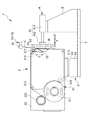
以下、本発明の実施形態について、図1〜図6を参照して説明する。図1は、本発明の一実施形態に係る印刷部を検査する検査装置1において、サーマルプリンタ2が印刷位置A1に位置する場合を示す平面図である。図2は、本発明の一実施形態に係る印刷部を検査する検査装置1において、カメラ5が撮像位置B1に位置する場合を示す平面図である。図3は、本発明に係る印刷部を検査する検査装置1において、印字受け部4が退避位置に位置する場合を示す側面図である。図4は、本発明に係る印刷部を検査する検査装置1において、図3に示す状態から、印字受け部4が押圧位置に移動された状態を示す側面図である。図5は、本発明に係る印刷部を検査する検査装置1において、図4に示す状態から、サーマルヘッド32が上方から下方に移動された状態を示す側面図である。図6は、本発明に係る印刷部を検査する検査装置1において、図5に示す状態から、印字受け部4が退避位置に移動された状態を示す側面図である。
Hereinafter, embodiments of the present invention will be described with reference to FIGS. FIG. 1 is a plan view showing a case where a thermal printer 2 is located at a printing position A1 in an inspection apparatus 1 for inspecting a printing unit according to an embodiment of the present invention. FIG. 2 is a plan view showing a case where the
なお、以下の説明及び図面において、本実施形態においては、空袋Eが移送される方向を移送方向Pという。また、移送方向Pに直交する方向であって印字受け部4が移動する方向を進退方向Xといい、印字受け部4がサーマルプリンタ2に近づく方向を進行方向X1といい、印字受け部4がサーマルプリンタ2から離間する方向を退行方向X2という。また、進退方向Xに直交する方向であってサーマルプリンタ2及びカメラ5が一体的に移動する方向を直動方向Yといい、カメラ5が撮像待機位置B2から撮像位置B1に向かう方向を第1直動方向Y1といい、カメラ5が撮像位置B1から撮像待機位置B2に向かう方向を第2直動方向Y2という。また、上下方向を上下方向Zという。
In the following description and drawings, the direction in which the empty bag E is transferred is referred to as a transfer direction P in this embodiment. The direction in which the print receiver 4 moves in the direction orthogonal to the transfer direction P is referred to as the forward / backward direction X, and the direction in which the print receiver 4 approaches the thermal printer 2 is referred to as the forward direction X1. A direction away from the thermal printer 2 is referred to as a backward direction X2. Further, the direction perpendicular to the advancing / retreating direction X and in which the thermal printer 2 and the
本実施形態の印刷部を検査する検査装置1は、例えば、給袋包装機10などにおける検査工程に用いられる。給袋包装機10とは、予め形成された袋であって内部に物が充填されていない空の袋(以下「空袋」という)(被印刷物)を供給して、空袋Eに充填物を充填して、袋に物を包装する機器である。本実施形態においては、空袋Eは、フィルム状のシートが袋状に形成されると共に、全体としてシート状に形成されており、一方側が開口している。
The inspection apparatus 1 that inspects the printing unit according to the present embodiment is used in an inspection process in a bag-
給袋包装機10においては、各工程を経て、空袋Eに充填物が充填されて包装される。給袋包装機10における各工程としては、例えば、プリンタとしてのサーマルプリンタ2により空袋Eに印刷部を印刷する印刷工程や、サーマルプリンタ2により印刷された印刷部を検査する検査工程や、空袋Eに充填物を充填する充填工程などがある。
In the bag supply and
給袋包装機10における各工程においては、空袋Eは、給袋包装機10の搬送機構11により、図1に示す移送方向Pに沿って、移送と停止とを繰り返して間欠的に順次移送される。空袋Eは、空袋Eの開口が上方側を向いて位置されると共にシート状の空袋Eの延在する表面が移送方向Pに略平行に配置された状態で、移送方向Pに沿って移送される。本実施形態においては、搬送機構11の一対の挟み爪部12は、空袋Eの上方側を移送方向Pにおける前端及び後端で挟み込んだ状態で移送方向Pに移動されるように構成され、空袋Eを移送方向Pに移送する。
In each process in the bag supply and
本実施形態においては、印刷部を検査する検査装置1は、例えば上述の給袋包装機10における印刷工程及び検査工程において、サーマルプリンタ2(後述)により印刷停止位置に停止中の空袋Eに印刷部が印刷されると共に、カメラ5(後述)により印刷停止位置に停止中の空袋Eに印刷された印刷部が撮像される。本実施形態における図1〜図6においては、空袋Eは、印刷停止位置に停止中である。
In the present embodiment, the inspection apparatus 1 that inspects the printing unit uses, for example, the empty bag E that is stopped at the print stop position by the thermal printer 2 (described later) in the printing process and the inspection process in the above-described bag feeding and
本実施形態の印刷部を検査する検査装置1は、図1〜図6に示すように、プリンタとしてのサーマルプリンタ2と、印字受け部4と、撮像部としてのカメラ5と、移動部としての直線移動部6と、載置板7と、を備える。
As shown in FIGS. 1 to 6, an inspection apparatus 1 for inspecting a printing unit according to this embodiment includes a thermal printer 2 as a printer, a print receiving unit 4, a
サーマルプリンタ2は、移送と停止とを繰り返して間欠的に移送される空袋Eが印刷停止位置に停止中において、印刷停止位置に停止中の空袋Eに印刷部(不図示)を印刷する。
また、サーマルプリンタ2は、図1及び図3に示すように、後述する直線移動部6に取り付けられている。詳細については後述するが、図1及び図2に示すように、サーマルプリンタ2は、後述する直線移動部6により、図1に示す印刷位置A1と、図2に示す印刷待機位置A2とに、移動可能に構成される。
The thermal printer 2 prints a printing unit (not shown) on the stopped empty bag E at the print stop position while the empty bag E that is intermittently transferred by repeatedly transferring and stopping is stopped at the print stop position. .
Moreover, the thermal printer 2 is attached to the linear moving
サーマルプリンタ2は、図1に示すように、リボン搬送機構31と、サーマルヘッド32と、保持枠体33と、を備える。保持枠体33には、リボン搬送機構31及びサーマルヘッド32が保持されている。
As shown in FIG. 1, the thermal printer 2 includes a
サーマルヘッド32は、図1及び図3に示すように、サーマルプリンタ2が印刷位置A1に位置する場合に、印刷停止位置に位置する空袋Eに対向して配置される。サーマルヘッド32は、先端側が空袋E側に突出するように配置される。サーマルヘッド32は、上下方向Zに移動可能に構成される。
As shown in FIGS. 1 and 3, the
サーマルヘッド32は、その先端に複数の発熱素子を備える。サーマルヘッド32は、サーマルプリンタ2がサーマルヘッド32に通電させることにより、所望の発熱素子が発熱する。
The
リボン搬送機構31は、図3に示すように、巻回された未使用のインクリボンRを回転自在に保持する原反側リボンホルダ311と、インクリボンRを巻き取る巻取側リボンホルダ316と、複数のガイドローラ312,313,314,315と、ピールローラ317と、を備える。リボン搬送機構31は、原反側リボンホルダ311に巻回された未使用のインクリボンRをサーマルヘッド32へ向けて搬送すると共に、サーマルヘッド32に使用されたインクリボンRを巻取側リボンホルダ316へ向けて搬送する。
As shown in FIG. 3, the
複数のガイドローラ312,313,314,315は、原反側リボンホルダ311から巻取側リボンホルダ316に向かって搬送されるインクリボンRをガイドするローラである。
The plurality of
ピールローラ317は、サーマルヘッド32よりもインクリボンRの搬送方向の下流側に設けられる。ピールローラ317は、回転可能に取り付けられている。ピールローラ317は、サーマルヘッド32と一体的に上下方向Zに移動する。ピールローラ317は、サーマルヘッド32により印刷が行われた後の使用済みのインクリボンRを、巻取側リボンホルダ316側に向けて送り出す。
The
印字受け部4は、図1及び図3に示すように、サーマルプリンタ2が印刷位置A1(図1参照)に位置する場合に、印刷停止位置に位置する空袋Eに対して、サーマルプリンタ2と反対側に配置される。印字受け部4は、支持部8を介して、載置板7の上面に載置されて固定されている。
As shown in FIGS. 1 and 3, the print receiving unit 4 is arranged so that the thermal printer 2 is located with respect to the empty bag E located at the print stop position when the thermal printer 2 is located at the print position A1 (see FIG. 1). And placed on the opposite side. The print receiving portion 4 is placed and fixed on the upper surface of the
印字受け部4は、図1及び図3に示すように、印字受け駆動部41と、保持板43と、プラテン板44と、を備える。印字受け駆動部41は、駆動部本体411と、ロッド部412と、を有する。駆動部本体411は、ロッド部412を進退可能に保持し、ロッド部412を進退方向X(進行方向X1、退行方向X2)に移動させる。
As shown in FIGS. 1 and 3, the print receiver 4 includes a print
ロッド部412の先端には、保持板43が取り付けられている。保持板43には、プラテン板44が取り付けられている。
A holding
プラテン板44は、空袋Eが印刷停止位置に位置する場合において、空袋E側の面が空袋Eに平行な平面を有する板状に形成される。プラテン板44は、例えば、シリコンゴム等の所定の弾性を有する部材により形成される。プラテン板44は、ロッド部412が進退方向Xに移動されることで、印刷停止位置に停止する空袋Eに対して、空袋Eに近づく進行方向X1又は空袋Eから離間する退行方向X2に移動される。
The
プラテン板44が印字受け駆動部41の駆動により進退方向Xに移動することにより、サーマルプリンタ2が印刷位置A1(図1参照)に位置する場合において、印刷停止位置に位置する空袋Eに対して、プラテン板44が空袋EをインクリボンR及びサーマルヘッド32側に押圧する押圧位置(図4参照)と、プラテン板44が空袋Eから離間する退避位置(図3参照)と、に移動可能である。本実施形態においては、印字受け駆動部41は、例えば、エアシリンダなどのアクチュエータにより構成されている。
When the
このように構成されるサーマルプリンタ2は、印刷位置A1(図1参照)において、印刷停止位置に停止中の空袋Eに印刷部(不図示)を印刷する。具体的には、空袋Eが印刷停止位置に停止中に、サーマルプリンタ2が印刷位置A1(図1参照)に位置している状態において、図3及び図4に示すように、印字受け部4のプラテン板44を、退避位置(図3参照)から押圧位置(図4参照)に向かうように進行方向X1に移動させる。これにより、印字受け部4のプラテン板44は、退避位置(図3参照)から押圧位置(図4参照)に移動されて、空袋Eを、インクリボンR及びサーマルヘッド32側に押圧する。そして、図4及び図5に示すように、サーマルヘッド32が上下方向Zにおける上方から下方に向けて移動されることにより、印字受け部4のプラテン板44の表面において、発熱した所望の発熱素子と接触したインクリボンRは、空袋Eに接触する。これにより、サーマルプリンタ2は、インクリボンRに塗布されたインクを空袋Eに接着させ、印刷部(不図示)を印刷する。
The thermal printer 2 configured as described above prints a printing unit (not shown) on the empty bag E that is stopped at the print stop position at the print position A1 (see FIG. 1). Specifically, when the empty bag E is stopped at the print stop position and the thermal printer 2 is positioned at the print position A1 (see FIG. 1), as shown in FIGS. The
カメラ5は、撮像位置B1(図2参照)において、印刷停止位置に停止中の空袋Eに印刷された印刷部を撮像する。カメラ5は、図1及び図2に示すように、サーマルプリンタ2の第2直動方向Y2側の側部に取り付けられている。
The
直線移動部6は、図2及び図3に示すように、載置板7の上面に載置されて固定されている。直線移動部6は、移動部本体61と、移動部本体61の上部側に設けられる上部移動部材62と、を有する。上部移動部材62の上端部には、サーマルプリンタ2の下部が取り付けられている。移動部本体61は、図1及び図2に示すように、上部移動部材62を直動方向Yに移動可能に保持し、上部移動部材62を直動方向Y(第1直動方向Y1、第2直動方向Y2)に移動させる。直動方向Yは、水平方向であって、ロッド部412の進退方向Xに直交する方向である。直動方向Yは、空袋Eの移送方向Pに略平行な方向でもある。本実施形態においては、直線移動部6は、例えば、ロッドレス方式のエアシリンダなどのアクチュエータにより構成される。
The
これにより、移動部本体61は、上部移動部材62を直動方向Yに移動させることにより、上部移動部材62に取り付けられたサーマルプリンタ2及びサーマルプリンタ2に取り付けられたカメラ5を、直線的に、直動方向Y(第1直動方向Y1、第2直動方向Y2)に一体的に移動させる。
Thus, the moving unit
直線移動部6により直動方向Yに移動されるサーマルプリンタ2は、印刷位置A1(図1参照)と、印刷待機位置A2(図2参照)と、に移動可能である。サーマルプリンタ2の印刷位置A1とは、図1に示すように、サーマルプリンタ2が印刷停止位置に停止中の空袋Eに対向する位置である。サーマルプリンタ2の印刷待機位置A2とは、図2に示すように、サーマルプリンタ2が印刷位置A1(図1参照)から第1直動方向Y1に離間した位置である。
The thermal printer 2 that is moved in the linear motion direction Y by the linear moving
直線移動部6により直動方向Yに移動されるカメラ5は、撮像位置B1(図2参照)と、撮像待機位置B2(図1参照)と、に移動可能である。カメラ5の撮像位置B1とは、図2に示すように、印刷停止位置に停止中の空袋Eに対向する位置である。カメラ5の撮像待機位置B2とは、図1に示すように、カメラ5の撮像位置B1(図2参照)から第2直動方向Y2に離間した位置である。
The
以上のように構成される直線移動部6は、サーマルプリンタ2における印刷位置A1(図1参照)から印刷待機位置A2(図2参照)への移動とカメラ5における撮像待機位置B2(図1参照)から撮像位置B1(図2参照)への移動とを同時に行うように、サーマルプリンタ2とカメラ5とを一体的に、直線的に、直動方向Yに移動させる。これにより、カメラ5は、サーマルプリンタ2が印刷位置A1(図1参照)から印刷待機位置A2(図2参照)への移動を開始した後に撮像位置B1(図2参照)へ移動して、撮像位置B1(図2参照)において印刷停止位置に停止中の空袋Eに印刷された印刷部を撮像する。
The linear moving
次に、印刷部を検査する検査装置1の動作について説明する。
まず、サーマルプリンタ2は、間欠して移送される空袋Eに印刷部を印刷する。具体的には、空袋Eは、移送と停止とを繰り返して間欠的に移送され、図1に示すように、印刷停止位置に停止している。また、サーマルプリンタ2は、図1に示すように、印刷位置A1に位置している。サーマルプリンタ2における印刷位置A1(図1参照)とは、印刷停止位置に停止中の空袋Eに対向する位置である。
Next, the operation of the inspection apparatus 1 that inspects the printing unit will be described.
First, the thermal printer 2 prints the printing unit on the empty bag E that is intermittently transferred. Specifically, the empty bag E is intermittently transferred by repeating transfer and stop, and is stopped at the print stop position as shown in FIG. Further, as shown in FIG. 1, the thermal printer 2 is located at a printing position A1. The printing position A1 (see FIG. 1) in the thermal printer 2 is a position facing the empty bag E that is stopped at the printing stop position.
次に、印字受け部4のプラテン板44を、駆動部本体411により図3に示す退避位置から図4に示す押圧位置に進行方向X1移動させて、印字受け部4のプラテン板44をサーマルヘッド32に押し付ける。その後、サーマルヘッド32を、図4に示す位置から図5に示す位置に、上下方向Zにおける上方から下方に向けて移動させる。そして、印字受け部4のプラテン板44を、駆動部本体411により図5に示す押圧位置から図6に示す退避位置に退行方向X2に移動させて、印字受け部4のプラテン板44を空袋Eから離間させる。このようにして、空袋Eには、印刷部(不図示)が印刷される。
Next, the
次に、カメラ5は、空袋Eが印刷停止位置に停止中に、サーマルプリンタ2により空袋Eに印刷された印刷部を撮像する。具体的には、空袋Eは、サーマルプリンタ2により印刷部が印刷された位置である印刷停止位置から移動せずに、印刷停止位置を維持している。カメラ5は、空袋Eが印刷停止位置を維持した停止中に、撮像待機位置B2(図1参照)から撮像位置B1(図2参照)に第1直動方向Y1に移動される。詳細には、直線移動部6により、サーマルプリンタ2及びカメラ5を、一体的に第1直動方向Y1に移動させる。これにより、カメラ5は、サーマルプリンタ2が印刷位置A1(図1参照)から印刷待機位置A2(図2参照)への移動を開始した後に、撮像位置B1(図2参照)に位置するように移動される。カメラ5は、撮像位置B1(図2参照)において、印刷停止位置に停止中の空袋Eに印刷された印刷部を撮像する。これにより、空袋Eを印刷停止位置から移動させずに、空袋Eをカメラ5により撮像することができる。従って、空袋Eに印刷された印刷部を精度よくカメラ5により撮像することができる。
Next, the
カメラ5により撮像された空袋Eの印刷部の画像の情報は、不図示の検査部に送信され、パターンマッチング等の処理が行われて検査される。これにより、空袋Eに印刷された印刷部を精度よく検査することができる。
Information on the image of the printing part of the empty bag E imaged by the
本実施形態の印刷部を検査する検査装置1によれば、例えば、以下の効果が奏される。
本実施形態の印刷部を検査する検査装置1においては、移送と停止とを繰り返して間欠的に移送される空袋Eが印刷停止位置に停止中において、印刷停止位置に停止中の空袋Eに印刷部を印刷するサーマルプリンタ2と、印刷停止位置に停止中の空袋Eに印刷された印刷部を撮像するカメラ5と、を備え、サーマルプリンタ2は、印刷位置A1において印刷停止位置に停止中の空袋Eに印刷部を印刷し、撮像部5は、サーマルプリンタ2が印刷位置A1から印刷待機位置A2への移動を開始した後に撮像位置B1へ移動して、撮像位置B1において印刷停止位置に停止中の空袋Eに印刷された印刷部を撮像する。
According to the inspection apparatus 1 that inspects the printing unit of the present embodiment, for example, the following effects are exhibited.
In the inspection apparatus 1 for inspecting the printing unit of the present embodiment, the empty bag E that is intermittently transferred by repeatedly transferring and stopping is stopped at the print stop position, and the empty bag E is stopped at the print stop position. A thermal printer 2 that prints the printing portion and a
そのため、空袋Eが印刷停止位置に停止中において、サーマルプリンタ2による空袋Eへの印刷部の印刷と、カメラ5による空袋Eに印刷された印刷部の撮像とを行うことができる。これにより、空袋Eが揺らぐなどして空袋Eが不安定な状態になることが抑制された状態で、サーマルプリンタ2により印刷された印刷部をカメラ5により精度よく撮像することができる。よって、サーマルプリンタ2により印刷された印刷部を精度よく検査することができる。
特に、空袋Eがフィルム状のシートにより形成される場合には、空袋Eが揺らぐなどして不安定な状態になる可能性が高まる。このような場合においても、サーマルプリンタ2により印刷された印刷部をカメラ5により精度よく撮像することができる。
Therefore, while the empty bag E is stopped at the print stop position, the printing of the printing unit onto the empty bag E by the thermal printer 2 and the imaging of the printing unit printed on the empty bag E by the
In particular, when the empty bag E is formed of a film-like sheet, the possibility that the empty bag E fluctuates and becomes unstable is increased. Even in such a case, the printing unit printed by the thermal printer 2 can be accurately imaged by the
また、空袋Eが印刷停止位置に停止中において、空袋Eへの印刷部の印刷と、空袋Eに印刷された印刷部の撮像と、の両方を行うことができる。これにより、空袋Eに印刷部を印刷するためのスペースと、空袋Eに印刷された印刷部を撮像するためのスペースと、の両方を設けなくてよいため、省スペース化を実現することができる。 In addition, while the empty bag E is stopped at the print stop position, both printing of the printing unit on the empty bag E and imaging of the printing unit printed on the empty bag E can be performed. Thereby, since it is not necessary to provide both a space for printing the printing part on the empty bag E and a space for imaging the printing part printed on the empty bag E, space saving can be realized. Can do.
また、本実施形態の印刷部を検査する検査装置1においては、サーマルプリンタ2における印刷位置A1から印刷待機位置A2への移動とカメラ5における撮像待機位置B2から撮像位置B1への移動とを同時に行うように、サーマルプリンタ2及びカメラ5を一体的に移動させる直線移動部6を更に備える。そのため、サーマルプリンタ2及びカメラ5を別々に移動させる移動部を備えなくてよいため、簡易な構成とすることができる。
In the inspection apparatus 1 for inspecting the printing unit of the present embodiment, the movement from the printing position A1 to the printing standby position A2 in the thermal printer 2 and the movement from the imaging standby position B2 to the imaging position B1 in the
以上、好適な実施形態について説明したが、本発明は前述した実施形態に限定されることなく種々の形態で実施することができる。
例えば、前述の実施形態においては、サーマルプリンタ2及びカメラ5を一体的に移動するように構成したが、これに制限されない。サーマルプリンタ2及びカメラ5を一体的に移動させずに、別々に移動させるように構成してもよい。
As mentioned above, although preferred embodiment was described, this invention can be implemented with a various form, without being limited to embodiment mentioned above.
For example, in the above-described embodiment, the thermal printer 2 and the
前記実施形態においては、プリンタをサーマルプリンタ2としたが、これに制限されず、例えば、インクジェットプリンタでもよい。 In the embodiment, the printer is the thermal printer 2, but the printer is not limited to this. For example, an ink jet printer may be used.
また、前記実施形態においては、被印刷物を、空袋Eとしたが、これに制限されない。被印刷物は、例えば、袋状に形成されない1枚のフィルム状のシート等であってもよい。 Moreover, in the said embodiment, although the to-be-printed object was the empty bag E, it is not restrict | limited to this. The substrate may be, for example, a single film sheet that is not formed in a bag shape.
また、前記実施形態においては、本発明の印刷部を検査する検査装置を、給袋包装機10に設けたが、これに制限されない。
Moreover, in the said embodiment, although the inspection apparatus which test | inspects the printing part of this invention was provided in the bag
また、前記実施形態においては、空袋Eの移送方向Pを直線状にしたが、これに制限されない。例えば、給袋包装機において、各工程のステーションが環状に沿って配置される場合があり、この場合には、空袋Eの移送方向Pを円弧状にしてもよい。この場合には、空袋Eが揺らぐなどして不安定な状態になる可能性が高まる。このような場合においても、サーマルプリンタ2により印刷された印刷部をカメラ5により精度よく撮像することができる。
Moreover, in the said embodiment, although the transfer direction P of the empty bag E was made into linear form, it is not restrict | limited to this. For example, in the bag-feeding packaging machine, the stations of the respective processes may be arranged along an annular shape. In this case, the transfer direction P of the empty bag E may be an arc. In this case, the possibility that the empty bag E fluctuates and becomes unstable is increased. Even in such a case, the printing unit printed by the thermal printer 2 can be accurately imaged by the
1 印刷部を検査する検査装置
2 サーマルプリンタ(プリンタ)
5 カメラ(撮像部)
6 直線移動部(移動部)
E 空袋(被印刷物)
A1 印刷位置
A2 印刷待機位置
B1 撮像位置
B2 撮像待機位置
1 Inspection device for inspecting printed parts 2 Thermal printer (printer)
5 Camera (imaging part)
6 Linear moving part (moving part)
E Empty bag (printed material)
A1 Print position A2 Print standby position B1 Imaging position B2 Imaging standby position
Claims (1)
前記印刷停止位置に停止中の前記被印刷物に印刷された前記印刷部を撮像する撮像部と、を備え、前記撮像部により撮像された前記印刷部を検査する検査装置であって、
前記プリンタは、前記印刷停止位置に停止中の前記被印刷物に対向する印刷位置と、前記印刷位置から離間した印刷待機位置と、に移動可能であり、前記印刷位置に停止した状態で前記印刷停止位置に停止中の前記被印刷物に前記印刷部を印刷し、
前記撮像部は、前記印刷停止位置に停止中の前記被印刷物に対向する撮像位置と、前記撮像位置から離間した撮像待機位置と、に移動可能であり、前記プリンタが前記印刷位置から前記印刷待機位置への移動を開始した後に前記撮像位置へ移動して、前記撮像位置に停止した状態で前記印刷停止位置に停止中の前記被印刷物に印刷された前記印刷部を撮像し、
前記印刷部を検査する検査装置は、前記プリンタにおける前記印刷位置から前記印刷待機位置への移動と前記撮像部における前記撮像待機位置から前記撮像位置への移動とを同時に行うように、前記プリンタ及び前記撮像部を一体的に移動させる移動部を更に備え、
前記プリンタは、前記撮像部が前記撮像待機位置に位置した状態で、前記印刷位置に停止して前記印刷部を印刷し、
前記撮像部は、前記プリンタが前記印刷待機位置に位置した状態で、前記撮像位置に停止して前記印刷部を撮像する、
印刷部を検査する検査装置。 A printer that prints a printing unit on the printing material that is stopped at the printing stop position when the printing material that is intermittently transferred by repeatedly transferring and stopping is stopped at the printing stop position;
An inspection unit that inspects the printing unit imaged by the imaging unit, and an imaging unit that images the printing unit printed on the printing material that is stopped at the printing stop position,
The printer includes a print position opposite to the printing substrate in stopping the printing stop position, and printing standby position separated from the printing position, it is movable in the printing stopped in a state of stopping the printing position Printing the printing section on the substrate being stopped at a position;
The image pickup unit is movable to an image pickup position facing the printing material stopped at the print stop position and an image pickup standby position spaced apart from the image pickup position, and the printer is moved from the print position to the print standby position. Move to the imaging position after starting to move to the position, image the printing unit printed on the printing material stopped at the print stop position in a state stopped at the imaging position ,
The inspection apparatus for inspecting the printing unit simultaneously performs the movement from the printing position to the printing standby position in the printer and the movement from the imaging standby position to the imaging position in the imaging unit. A moving unit that moves the imaging unit integrally;
In the state where the imaging unit is located at the imaging standby position, the printer stops at the printing position and prints the printing unit.
The imaging unit stops at the imaging position and images the printing unit in a state where the printer is positioned at the print standby position;
Inspection device that inspects the printing section.
Priority Applications (1)
| Application Number | Priority Date | Filing Date | Title |
|---|---|---|---|
| JP2013085968A JP6224339B2 (en) | 2013-04-16 | 2013-04-16 | Inspection device for inspecting printed parts |
Applications Claiming Priority (1)
| Application Number | Priority Date | Filing Date | Title |
|---|---|---|---|
| JP2013085968A JP6224339B2 (en) | 2013-04-16 | 2013-04-16 | Inspection device for inspecting printed parts |
Publications (2)
| Publication Number | Publication Date |
|---|---|
| JP2014209067A JP2014209067A (en) | 2014-11-06 |
| JP6224339B2 true JP6224339B2 (en) | 2017-11-01 |
Family
ID=51903379
Family Applications (1)
| Application Number | Title | Priority Date | Filing Date |
|---|---|---|---|
| JP2013085968A Expired - Fee Related JP6224339B2 (en) | 2013-04-16 | 2013-04-16 | Inspection device for inspecting printed parts |
Country Status (1)
| Country | Link |
|---|---|
| JP (1) | JP6224339B2 (en) |
Family Cites Families (6)
| Publication number | Priority date | Publication date | Assignee | Title |
|---|---|---|---|---|
| DE68923958T2 (en) * | 1989-04-20 | 1996-04-25 | Hewlett Packard Co | Printing system and method for creating visible markings on a support. |
| JP2002005843A (en) * | 2000-06-19 | 2002-01-09 | Nsd Corp | Inspecting method and apparatus for carved character |
| KR100609912B1 (en) * | 2004-08-26 | 2006-08-09 | 삼성전자주식회사 | Panel inspection apparatus and control method thereof |
| US7424902B2 (en) * | 2004-11-24 | 2008-09-16 | The Boeing Company | In-process vision detection of flaw and FOD characteristics |
| JP4629513B2 (en) * | 2005-06-21 | 2011-02-09 | エヌエスディ株式会社 | Stamped character inspection method and inspection device |
| JP5399224B2 (en) * | 2009-12-11 | 2014-01-29 | 東洋自動機株式会社 | Bag packing machine |
-
2013
- 2013-04-16 JP JP2013085968A patent/JP6224339B2/en not_active Expired - Fee Related
Also Published As
| Publication number | Publication date |
|---|---|
| JP2014209067A (en) | 2014-11-06 |
Similar Documents
| Publication | Publication Date | Title |
|---|---|---|
| JP5399224B2 (en) | Bag packing machine | |
| CA2826762C (en) | Packaging bag feeder in packaging machine | |
| JP4985753B2 (en) | Screen printing system and mask cleaning method for screen printing system | |
| JP2015222370A (en) | Exposure apparatus | |
| TW201414565A (en) | Solder ball printing mounted apparatus | |
| JP5062243B2 (en) | Screen printing system and mask cleaning method for screen printing system | |
| KR101391346B1 (en) | Apparatus and method for manufacturing printed plate board | |
| JP6224339B2 (en) | Inspection device for inspecting printed parts | |
| JP6738668B2 (en) | Print inspection device | |
| JP2010129866A (en) | Conductive ball mounting device | |
| JP6196116B2 (en) | Empty bag supply inspection device | |
| JP6269152B2 (en) | Printing apparatus and printing method | |
| EP2754560B1 (en) | Recording apparatus | |
| KR101212359B1 (en) | Handler for film-type chip | |
| US11198312B2 (en) | Method for determining working gap, and recording device | |
| TWI748186B (en) | Printing systemand printing method | |
| JP6168969B2 (en) | Thermal printer device | |
| JP7122867B2 (en) | Print department inspection device | |
| JP2007216648A (en) | Correcting method and compensating apparatus | |
| JP6732058B2 (en) | Thermal printer | |
| US8669732B2 (en) | Encoder for a printer and method | |
| JP2011126050A (en) | Screen printing system and method for cleaning mask of screen printing system | |
| JP2015063027A (en) | Printer and printing method | |
| JP2015006952A (en) | Transfer device | |
| JP2014214001A (en) | Printer |
Legal Events
| Date | Code | Title | Description |
|---|---|---|---|
| A621 | Written request for application examination |
Free format text: JAPANESE INTERMEDIATE CODE: A621 Effective date: 20160316 |
|
| A977 | Report on retrieval |
Free format text: JAPANESE INTERMEDIATE CODE: A971007 Effective date: 20170213 |
|
| A131 | Notification of reasons for refusal |
Free format text: JAPANESE INTERMEDIATE CODE: A131 Effective date: 20170228 |
|
| A521 | Written amendment |
Free format text: JAPANESE INTERMEDIATE CODE: A523 Effective date: 20170428 |
|
| TRDD | Decision of grant or rejection written | ||
| A01 | Written decision to grant a patent or to grant a registration (utility model) |
Free format text: JAPANESE INTERMEDIATE CODE: A01 Effective date: 20170926 |
|
| A61 | First payment of annual fees (during grant procedure) |
Free format text: JAPANESE INTERMEDIATE CODE: A61 Effective date: 20171005 |
|
| R150 | Certificate of patent or registration of utility model |
Ref document number: 6224339 Country of ref document: JP Free format text: JAPANESE INTERMEDIATE CODE: R150 |
|
| LAPS | Cancellation because of no payment of annual fees |