JP6218396B2 - Printing device - Google Patents
Printing device Download PDFInfo
- Publication number
- JP6218396B2 JP6218396B2 JP2013044574A JP2013044574A JP6218396B2 JP 6218396 B2 JP6218396 B2 JP 6218396B2 JP 2013044574 A JP2013044574 A JP 2013044574A JP 2013044574 A JP2013044574 A JP 2013044574A JP 6218396 B2 JP6218396 B2 JP 6218396B2
- Authority
- JP
- Japan
- Prior art keywords
- printing
- power supply
- power
- reading
- unit
- Prior art date
- Legal status (The legal status is an assumption and is not a legal conclusion. Google has not performed a legal analysis and makes no representation as to the accuracy of the status listed.)
- Expired - Fee Related
Links
Images


Classifications
-
- H—ELECTRICITY
- H04—ELECTRIC COMMUNICATION TECHNIQUE
- H04N—PICTORIAL COMMUNICATION, e.g. TELEVISION
- H04N1/00—Scanning, transmission or reproduction of documents or the like, e.g. facsimile transmission; Details thereof
- H04N1/00885—Power supply means, e.g. arrangements for the control of power supply to the apparatus or components thereof
- H04N1/00904—Arrangements for supplying power to different circuits or for supplying power at different levels
-
- G—PHYSICS
- G06—COMPUTING; CALCULATING OR COUNTING
- G06F—ELECTRIC DIGITAL DATA PROCESSING
- G06F1/00—Details not covered by groups G06F3/00 - G06F13/00 and G06F21/00
- G06F1/26—Power supply means, e.g. regulation thereof
- G06F1/32—Means for saving power
-
- G—PHYSICS
- G06—COMPUTING; CALCULATING OR COUNTING
- G06F—ELECTRIC DIGITAL DATA PROCESSING
- G06F3/00—Input arrangements for transferring data to be processed into a form capable of being handled by the computer; Output arrangements for transferring data from processing unit to output unit, e.g. interface arrangements
- G06F3/12—Digital output to print unit, e.g. line printer, chain printer
- G06F3/1201—Dedicated interfaces to print systems
- G06F3/1202—Dedicated interfaces to print systems specifically adapted to achieve a particular effect
- G06F3/1218—Reducing or saving of used resources, e.g. avoiding waste of consumables or improving usage of hardware resources
- G06F3/1221—Reducing or saving of used resources, e.g. avoiding waste of consumables or improving usage of hardware resources with regard to power consumption
-
- G—PHYSICS
- G06—COMPUTING; CALCULATING OR COUNTING
- G06F—ELECTRIC DIGITAL DATA PROCESSING
- G06F3/00—Input arrangements for transferring data to be processed into a form capable of being handled by the computer; Output arrangements for transferring data from processing unit to output unit, e.g. interface arrangements
- G06F3/12—Digital output to print unit, e.g. line printer, chain printer
- G06F3/1201—Dedicated interfaces to print systems
- G06F3/1223—Dedicated interfaces to print systems specifically adapted to use a particular technique
- G06F3/1229—Printer resources management or printer maintenance, e.g. device status, power levels
-
- G—PHYSICS
- G06—COMPUTING; CALCULATING OR COUNTING
- G06K—GRAPHICAL DATA READING; PRESENTATION OF DATA; RECORD CARRIERS; HANDLING RECORD CARRIERS
- G06K15/00—Arrangements for producing a permanent visual presentation of the output data, e.g. computer output printers
- G06K15/40—Details not directly involved in printing, e.g. machine management, management of the arrangement as a whole or of its constitutive parts
- G06K15/4055—Managing power consumption, e.g. standby mode
-
- H—ELECTRICITY
- H04—ELECTRIC COMMUNICATION TECHNIQUE
- H04N—PICTORIAL COMMUNICATION, e.g. TELEVISION
- H04N1/00—Scanning, transmission or reproduction of documents or the like, e.g. facsimile transmission; Details thereof
- H04N1/00885—Power supply means, e.g. arrangements for the control of power supply to the apparatus or components thereof
- H04N1/00888—Control thereof
- H04N1/00891—Switching on or off, e.g. for saving power when not in use
-
- G—PHYSICS
- G06—COMPUTING; CALCULATING OR COUNTING
- G06F—ELECTRIC DIGITAL DATA PROCESSING
- G06F3/00—Input arrangements for transferring data to be processed into a form capable of being handled by the computer; Output arrangements for transferring data from processing unit to output unit, e.g. interface arrangements
- G06F3/12—Digital output to print unit, e.g. line printer, chain printer
- G06F3/1201—Dedicated interfaces to print systems
- G06F3/1202—Dedicated interfaces to print systems specifically adapted to achieve a particular effect
- G06F3/121—Facilitating exception or error detection and recovery, e.g. fault, media or consumables depleted
-
- H—ELECTRICITY
- H04—ELECTRIC COMMUNICATION TECHNIQUE
- H04N—PICTORIAL COMMUNICATION, e.g. TELEVISION
- H04N2201/00—Indexing scheme relating to scanning, transmission or reproduction of documents or the like, and to details thereof
- H04N2201/0077—Types of the still picture apparatus
- H04N2201/0094—Multifunctional device, i.e. a device capable of all of reading, reproducing, copying, facsimile transception, file transception
-
- Y—GENERAL TAGGING OF NEW TECHNOLOGICAL DEVELOPMENTS; GENERAL TAGGING OF CROSS-SECTIONAL TECHNOLOGIES SPANNING OVER SEVERAL SECTIONS OF THE IPC; TECHNICAL SUBJECTS COVERED BY FORMER USPC CROSS-REFERENCE ART COLLECTIONS [XRACs] AND DIGESTS
- Y02—TECHNOLOGIES OR APPLICATIONS FOR MITIGATION OR ADAPTATION AGAINST CLIMATE CHANGE
- Y02D—CLIMATE CHANGE MITIGATION TECHNOLOGIES IN INFORMATION AND COMMUNICATION TECHNOLOGIES [ICT], I.E. INFORMATION AND COMMUNICATION TECHNOLOGIES AIMING AT THE REDUCTION OF THEIR OWN ENERGY USE
- Y02D10/00—Energy efficient computing, e.g. low power processors, power management or thermal management
Landscapes
- Engineering & Computer Science (AREA)
- Theoretical Computer Science (AREA)
- General Engineering & Computer Science (AREA)
- Physics & Mathematics (AREA)
- General Physics & Mathematics (AREA)
- Human Computer Interaction (AREA)
- Multimedia (AREA)
- Signal Processing (AREA)
- Accessory Devices And Overall Control Thereof (AREA)
- Facsimiles In General (AREA)
- Power Sources (AREA)
Description
本発明は、印刷装置に関するものである。 The present invention relates to a printing apparatus.
従来型の画像形成装置では、ユーザの利便性や制御の簡便さなどを優先させるため、装置を構成する各要素(プリント装置、スキャン装置など)ごと個別に電源供給を開始したり停止したりする構成を採用していなかった。 In conventional image forming apparatuses, in order to prioritize user convenience and ease of control, power supply is started and stopped individually for each element (printing apparatus, scanning apparatus, etc.) constituting the apparatus. The configuration was not adopted.
しかし、近年では、画像形成装置に対する省電力化の要求が高まっているため、画像形成装置内で動作する機能によって、各構成要素ごとに個別に電源供給状態を制御できる構成にする提案がなされている(特許文献1)。これにより、いっそうの画像形成装置の省電力化が図られることが期待される。 However, in recent years, there has been an increasing demand for power saving for the image forming apparatus, and therefore a proposal has been made for a configuration in which the power supply state can be individually controlled for each component by a function that operates in the image forming apparatus. (Patent Document 1). As a result, further power saving of the image forming apparatus is expected.
画像形成装置を構成するためのメカニカルリレーやモータといった稼働部品、光源といった高温になる部品などは消耗部品とされ電源供給、切断の回数に対して動作品質が保証できる上限回数といった制限がある事が多い。 Operating parts such as mechanical relays and motors that constitute the image forming apparatus, and parts that reach high temperatures such as light sources are consumable parts, and there may be a limit such as the maximum number of times that the operation quality can be guaranteed for the number of times of power supply and cutting Many.
しかし、前出の特許文献1のような構成において、電源供給、切断を比較的短時間で繰り返すような制御を行うと、想定されている画像形成装置自身の寿命よりも短い期間で耐久回数を超えてしまうことが容易に想像できる。
However, in the configuration as in the above-mentioned
これは画像形成装置を構成する部品の動作品質が保証できなくため、その結果として画像形成装置そのものの寿命が短くなり、画像形成装置のさらなる省電力化と、装置の寿命の両立は技術的に困難であった。 This is because the operation quality of the components constituting the image forming apparatus cannot be guaranteed, and as a result, the life of the image forming apparatus itself is shortened, and further power saving of the image forming apparatus and compatibility between the life of the apparatus are technically necessary. It was difficult.
本発明は、上記の課題を解決するためになされたもので、本発明の目的は、ユーザにより選択される機能に適応して各部への電源供給制御を行うことで、装置全体における節電要求を満たしつつ、各部の寿命も延命できる仕組みを提供することである。 The present invention has been made to solve the above-described problems, and an object of the present invention is to control power supply to each unit in accordance with a function selected by a user, thereby satisfying a power saving request in the entire apparatus. It is to provide a mechanism that can extend the life of each part while satisfying.
上記目的を達成する本発明の画像形成装置は以下に示す構成を備える。
用紙に画像を印刷する印刷手段と、原稿の画像を読み取る読取手段と、前記印刷手段及び前記読取手段に電力を供給する電力供給手段と、第1保証時間と、前記第1保証時間よ りも短い第2保証時間とを記憶する記憶手段と、前記読取手段が原稿の画像を読み取り且つ前記印刷手段が前記読取手段によって読み取られた原稿の画像に基づいて用紙に画像を印刷するコピー処理を実行し、前記コピー処理にともない計時し、前記計時が前記第2保 証時間を経過したことに基づき前記電力供給手段による前記読取手段への電力供給を停止 させ、前記計時が前記第1保証時間を経過したことに基づき前記電力供給手段による前記印刷手段への電力供給を停止させる制御手段と、を備えることを特徴とする。The image forming apparatus of the present invention that achieves the above object has the following configuration.
A printing unit for printing an image on a sheet, a reading means for reading an image of an original, and a power supply means for supplying electric power to said printing means and said reading means, and a first guarantee time, by the first guarantee time remote A storage unit that stores a short second guarantee time, and a copy process in which the reading unit reads an image of a document and the printing unit prints an image on a sheet based on the image of the document read by the reading unit. and, the timed with the copying process, the time counter stops the power supply to said reading means by said power supply means based on that passed the second guarantee time, the time counter is the first guarantee time control means for causing stopping power supply to the elapsed that on the basis of said power supply means by said printing means, characterized in that it comprises a.
本発明によれば、ユーザにより選択される機能に適応して各部への電源供給制御を行うことで、装置全体における節電要求を満たしつつ、各部の寿命も延命できる。 According to the present invention, by performing power supply control to each unit in accordance with a function selected by the user, it is possible to extend the life of each unit while satisfying the power saving request in the entire apparatus.
次に本発明を実施するための最良の形態について図面を参照して説明する。
<システム構成の説明>
〔第1実施形態〕
Next, the best mode for carrying out the present invention will be described with reference to the drawings.
<Description of system configuration>
[First Embodiment]
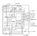
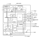
図1は、本実施形態を示す画像形成装置の一例を示すブロック図である。本例は、画像形成装置として、複合画像機能処理を行うMFP(Multi Function Printer)を例とする。
本実施形態では、種別の異なる機能処理を行う複数の処理手段として、スキャナ装置、プリンタ装置、画像処理装置等を備え、これらの処理手段を組み合わせて上記複合画像処理機能を実現する構成となっている。また、本実施形態の画像形成装置は、各処理手段に電源を供給する電源装置6を備える。
さらに、本実施形態を示す画像形成装置において、後述する操作部8に表示されるUI画面を用いて、選択可能な機能処理は、コピー機能処理、ファクシミリ機能処理、送信機能処理、ボックス機能処理が含まれる。
FIG. 1 is a block diagram illustrating an example of an image forming apparatus according to the present exemplary embodiment. In this example, an MFP (Multi Function Printer) that performs composite image function processing is taken as an example of the image forming apparatus.
In this embodiment, a scanner device, a printer device, an image processing device, and the like are provided as a plurality of processing means for performing different types of function processing, and the above-described composite image processing function is realized by combining these processing means. Yes. The image forming apparatus according to the present exemplary embodiment includes a
Further, in the image forming apparatus showing the present embodiment, function functions that can be selected using a UI screen displayed on the
図1において、2はスキャナ装置で、原稿から光学的に画像を読み取りデジタル画像に変換する。3はコントローラで、電話回線等にデジタル画像を送信するFAX装置7と、これらと接続され各モジュールに指示を出す事により画像形成装置上でジョブを実行する。
4はプリンタ装置で、デジタル画像を紙デバイスに出力する。8は操作部で、本装置に対する操作指示を受け付けるため、ハードキーと、LCD表示器等を備える。
14はハードディスク装置で、操作部8、デジタル画像や制御プログラム等を記憶する。なお、画像形成装置1は、LAN9経由でコンピュータ10からデジタル画像の入出力、ジョブの発行や機器の指示等も行なうことが可能である。In FIG. 1,
A
A
11は原稿給紙ユニットで、スキャナ装置2は自動的に原稿束を逐次入れ替える。12はスキャナユニットで、原稿を光学スキャンしデジタル画像に変換し、変換された画像データはコントローラ3に送信する。
プリンタ装置4は、紙束から一枚ずつ逐次給紙可能な給紙ユニット18、給紙した紙に画像データを印刷するためのマーキングユニット16、印刷後の紙を排紙するための排紙ユニット17から成る。
コントローラ3はCPU13を有し、スキャナ装置2及びプリンタ装置4と画像データの送受信及び保存を行う。すなわち、コントローラ3ではスキャナ装置2から受信した画像データを、メモリ15に一時保存する。その後、ハードディスク装置14へと画像データを格納する事で画像のスキャンと保存が完了する。
コントローラ3は、ハードディスク装置14から画像データをメモリ15に一時保存し、メモリ15からプリンタ装置4に画像データを送信することによりプリント出力を行うことができる。
The
The
The
また、汎用画像処理部19を有し、メモリ15に保存した画像データを汎用画像処理部19で、例えば縮小等の処理を行ったものを再度メモリ15に保存することが可能な画像処理装置5を持っている。この汎用画像処理部19は必要に応じて様々な場面で使用する。
画像形成装置1は、コントローラ3が制御する操作部8を有し、オペレータ操作もしくは、LAN9からの指示をCPU13が解釈し、多彩なジョブを実行可能である。
以下、画像形成装置の機能処理例を説明する。本実施形態では、機能処理として以下に示す選択可能な機能処理は、コピー機能処理、ファクシミリ機能処理、送信機能処理、ボックス機能処理を実行可能に構成されている。
〔複写機能〕
スキャナ装置2から読み込んだ画像をハードディスク装置14に保存し、同時にプリンタ装置4を使用して印刷を行なう。
In addition, the
The
Hereinafter, an example of functional processing of the image forming apparatus will be described. In the present embodiment, selectable function processing shown below as function processing is configured to be able to execute copy function processing, facsimile function processing, transmission function processing, and box function processing.
[Copy function]
The image read from the
〔画像送信機能〕
スキャナ装置2から読み込んだ画像をハードディスク装置14に保存し、LAN9を経由してコンピュータ10に送信する。
〔画像保存機能〕
スキャナ装置2から読み込んだ画像をハードディスク装置14に保存し、必要に応じて画像送信や画像印刷を行なう。
(Image transmission function)
The image read from the
(Image saving function)
The image read from the
〔画像印刷機能〕
コンピュータ10から送信された例えばページ記述言語を解析し、プリンタ装置4で印刷する。
〔FAX受信プリント〕
FAX装置7から受信したFAX画像をハードディスク装置14に保存し、同時にプリンタ装置4を使用して印刷を行う。
(Image printing function)
For example, the page description language transmitted from the
[FAX reception print]
The FAX image received from the FAX apparatus 7 is stored in the
〔FAX転送処理〕
FAX装置7から受信したFAX画像をハードディスク装置14に保存し、同時にLAN9を経由してコンピュータ10等に転送する。
〔FAXメモリ受信処理〕
FAX装置7から受信したFAX画像をハードディスク装置14に保存し、オペレータからの参照を待つ。
[FAX transfer processing]
The FAX image received from the FAX apparatus 7 is stored in the
[FAX memory reception processing]
The FAX image received from the FAX apparatus 7 is stored in the
〔FAX送信処理〕
スキャナ装置2から読み込んだ画像をハードディスク装置14に保存し、同時にFAX装置7から公衆回線に送信する。
なお、多くのケースでハードディスク装置14を介在するのは、ジョブに失敗した場合や、電源断等の異常状態からリカバリするためである。
電源装置6は、画像形成装置1における電源を供給する装置である。
装置OFF時、AC電源29はスイッチ30により絶縁されている。
スイッチ30をONにすることでAC−DCコンバータ20にAC電源が供給され、DC電源が作られる。この装置はCPU13の指示により装置全体を4つの独立した電源制御が可能である。すなわち、CPU13からのスイッチ21により、コントローラ部電力25の電源をOFF/ON制御可能である。
[FAX transmission processing]
The image read from the
In many cases, the
The
When the apparatus is OFF, the AC power supply 29 is insulated by the switch 30.
When the switch 30 is turned on, AC power is supplied to the AC-
同様に、スイッチ22はプリンタ部電力28、スイッチ23はスキャナ部電力26、スイッチ24は汎用画像処理部電力27の電源をOFF/ON制御可能である。
CPU13はこれらのスイッチ21から24を用いることで、適切に画像形成装置1の必要な場所に電力を供給する。本実施形態では、第1処理手段、第2処理手段として機能する各処理手段は、電源の切断または接続を行うスイッチを備えている。なお、CPU13は、選択された機能がコピー機能である場合、スキャナ、プリンタ、画像処理装置のそれぞれに電力を供給するように制御している。
以下に各電力状態ついて説明する。
Similarly, the
The
Each power state will be described below.
〔スリープ状態〕
このモードは画像形成装置1自体の電力を可能な限り落した状態である。
[Sleep state]
In this mode, the power of the
CPU13の周辺デバイスは一般的なサスペンド状態(ACPI−S3等)とし、ジョブを検出可能な部分(スリープ時電力31)のみの通電を行い、装置全体の電力を非常に少ない電力状態にすることができる。
具体的には、CPU13は装置の状態をメモリ15に保存し、スイッチ21により自分自身を含むコントローラ部電力25の電源を落とす。
この時、CPU13自身が動作しなくなるが、スリープ時電力31がハード的にONされ、ジョブが来たことだけが分かる状態となる。
そして例えば、LAN9からのネットワーク受信、FAX装置7からのFAXコール、操作部8の操作がなされた時に、ハードウエア的にコントローラ部電力25がONとなる。
Peripheral devices of the
Specifically, the
At this time, the
For example, when a network reception from the LAN 9, a FAX call from the FAX apparatus 7, or an operation of the
CPU13はメモリ15に保存された装置の状態をメモリ15から読みだして、再設定を行い、コントローラ部電力25の電源がOFFされる直前の状態に復帰し、スタンバイ状態へと移行する。
スリープ状態はハードウエアの多くが動作できない状態であるため、スタンバイ状態に遷移するだけの機能しかない。ジョブはスタンバイ状態に移行してから受け付ける。
The
Since the sleep state is a state in which most of the hardware cannot operate, it has only a function for making a transition to the standby state. The job is accepted after shifting to the standby state.
〔スタンバイ状態〕
コントローラ部電力25が通電されている状態である。
操作部8からのオペレータによる操作、LAN9からのネットワーク経由のジョブ等を受け付ける。
[Standby]
This is a state where the controller power 25 is energized.
An operation by an operator from the
プリンタ部電力28、スキャナ部電力26、汎用画像処理部電力27はOFFとなっているため、CPU13はスイッチ22から24の使用するデバイスの電源を通電させた後に、所定のジョブを実行する。例えば以下のようにジョブ種に応じて各デバイスの電源をONにする。
〔複写機能〕
スキャナ部電力26と汎用画像処理部電力27とプリンタ部電力28をONにし、先に述べたように複写機能を実現する。
Since the printer unit power 28, the scanner unit power 26, and the general-purpose image processing unit power 27 are OFF, the
[Copy function]
The scanner unit power 26, the general-purpose image processing unit power 27, and the printer unit power 28 are turned on to realize the copying function as described above.
〔画像送信機能〕
キャナ部電力26と汎用画像処理部電力27をONにし、読みとった画像データを送信する。
〔画像保存機能〕
スキャナ部電力26と汎用画像処理部電力27をONにし、読みとった画像データを保存する。(Image transmission function )
The CAN unit power 26 and the general-purpose image processing unit power 27 are turned ON, and the read image data is transmitted.
(Image saving function)
The scanner unit power 26 and the general-purpose image processing unit power 27 are turned on, and the read image data is stored.
〔ボックス印刷機能〕
プリンタ部電力28と汎用画像処理部電力27をONにし、様々な画像データを印刷する。
〔FAX受信プリント〕
プリンタ部電力28と汎用画像処理部電力27をONにし、受信したFAX画像に汎用画像処理を施したのちに印刷する。
[Box printing function]
The printer unit power 28 and the general-purpose image processing unit power 27 are turned on to print various image data.
[FAX reception print]
The printer unit power 28 and the general-purpose image processing unit power 27 are turned on, and the received FAX image is subjected to general-purpose image processing and then printed.
〔FAX転送処理〕
汎用画像処理部電力27のみをONにし、FAX受信したデータを汎用画像処理したのちに転送する。
〔FAXメモリ受信処理〕
汎用画像処理部電力27のみをONにし、FAX受信したデータを汎用画像処理した後、ハードディスク装置14に保存する。
[FAX transfer processing]
Only the general-purpose image processing unit power 27 is turned ON, and the data received by FAX is transferred after general-purpose image processing.
[FAX memory reception processing]
Only the general-purpose image processing unit power 27 is turned on, and the data received by FAX is subjected to general-purpose image processing and then stored in the
〔FAX送信処理〕
スキャナ部電力26と汎用画像処理部電力27をONにし、読み込んだFAX画像データを公衆回線に送信する。
ジョブが完了したらデバイスの電源を落とすことで、使用する時だけ必要なデバイスのみを通電させることが可能となり、スタンバイ時の待機電力を削減することが可能となる。
[FAX transmission processing]
The scanner unit power 26 and the general-purpose image processing unit power 27 are turned on, and the read FAX image data is transmitted to the public line.
When the job is completed, by turning off the power of the device, only the necessary device can be energized only when it is used, and the standby power during standby can be reduced.
図2は、図1に示した画像形成装置の各部の電源投入状態を説明する図である。本例では、画像形成装置の操作部で選択されている機能に対応する、画像形成装置を構成する各要素の電源系統の状態と、各構成要素が必要とする電源投入状態を維持すべき最低保証時間を対応づけられた例を示す。具体的には、各処理手段に電源を供給し続けるべき保証時間と、選択される機能に対応づけて各処理手段に供給する電源の状態をオン状態、またはオフ状態とすべき電源移行状態とが後述する状態記憶部に記憶される。以下、各部の電源状態を説明する。なお、本図に示す最低保障時間や電源移行状態は、テーブルとしてハードディスク装置14に記憶されているものとするが、他の記憶媒体、例えばフラッシュROM、EEPROM(登録商標)等に記憶されていてもよい。
また、画像形成装置に電源が供給された後は、ハードディスク装置14からメモリ15に読み込まれて、CPU13が随時読み出し可能に管理される。FIG. 2 is a diagram illustrating a power-on state of each unit of the image forming apparatus illustrated in FIG. In this example, the state of the power supply system of each element constituting the image forming apparatus corresponding to the function selected in the operation unit of the image forming apparatus and the minimum power-on state required for each component are to be maintained. An example in which guaranteed times are associated is shown. Specifically, the guaranteed time to continue supplying power to each processing means, and the power supply transition state to turn on or off the power supply state to be supplied to each processing means in association with the selected function Is stored in a state storage unit to be described later. Hereinafter, the power state of each unit will be described. The minimum guaranteed time and the power transfer state shown in the figure are stored in the
In addition, after power is supplied to the image forming apparatus, the image is read from the
図2において、ユーザによってコピー機能選択状態204では、ユーザによりコピー機能選択が選択されている場合に対応し、スキャナ装置2、プリンタ装置4、画像処理装置5いずれの構成要素も全て電源を投入する状態にしておくことを表す。
また、同様にFAX機能選択状態206では、FAX機能選択が選択されている場合にはスキャナ装置2、画像処理装置は電源投入状態、プリンタ装置は電源切断状態にしておくことを表している(図8)。さらに、他の例としてユーザによる機能選択待ちのユーザ認証状態、送信機能選択状態、ボックス機能選択状態205を表している。
In FIG. 2, in the copy
Similarly, in the FAX
次に最低保証時間について説明する。
ここで、保証時間とは、電源切断の状態から電源投入の状態に変化した時に最低限電源投入状態を維持すべき時間である。
図1のスキャナ装置2にあるスイッチ32、プリンタ装置4にあるスイッチ33にはメカニカルリレーが採用されており、消耗部品であるため、動作品質が保証できる耐久回数がある。動作電圧や電流、周辺温度などにも影響されるため一概には言えないが20万回程度が一般的である。
Next, the minimum guarantee time will be described.
Here, the guaranteed time is a time during which the power-on state should be maintained at a minimum when the power-off state is changed to the power-on state.
Since the mechanical relay is employed for the
仮に1時間あたり10回電源切断・投入が行われると仮定し1日8時間稼働すると、年間で29、200回リレーが動作し7年弱で耐久回数を迎えることになる。
仮に画像形成装置の寿命をこの程度と仮定すると、6分間は電源投入時間を保持する必要があることがわかる。このため数値としてプリンタ装置の保証時間は、360秒になる。
Assuming that the power is turned off and on 10 times per hour and operated for 8 hours a day, the relay operates 29,200 times a year and reaches the endurance number in less than 7 years.
Assuming that the life of the image forming apparatus is about this level, it can be seen that the power-on time must be maintained for 6 minutes. For this reason, the guaranteed time of the printer device is 360 seconds as a numerical value.
しかし、保証時間が長いと省電力状態へ移行するまでの時間が長くなり、結果として消費電力が多くなってしまうため、できるだけ短いことが望ましい。その対応例としては、メカニカルリレーを用いるのではなく、半導体リレーを用いることである。半導体リレーでは機械的な可動部がなくなる分だけ耐久回数が多くなることが知られており、ほぼ無制限であるとされている。
本実施形態では、画像処理装置5のスイッチ34がそれを採用していると仮定している。このため画像処理装置5の保証時間207は、図2に示すように、5秒と短く設定している。なお、第1種類,第2種類の各機能に対応づけられる保証時間207は、一例であり、画像形成装置を構成する上記部材の仕様に適応して設定される。
However, if the guarantee time is long, it takes a long time to shift to the power saving state, resulting in an increase in power consumption. As a corresponding example, a semiconductor relay is used instead of a mechanical relay. It is known that the number of endurances increases as long as there are no mechanical moving parts in the semiconductor relay, and it is said to be almost unlimited.
In the present embodiment, it is assumed that the switch 34 of the
図3は、図1に示した操作部8に表示される機能選択画面を示す平面図である。
なお、本例に示す操作部8は機能選択ボタン2000、テンキー2020、コピースタートボタン2030、操作停止ボタン2031、モード切替ボタン2040を備える。さらに、操作部8は、データ入力キー2051、2052、ワンタッチダイヤルボタン2060を備える。さらに、操作ユニット180は、各種のユーザインタフェースを表示可能なLCD表示器2010を備える。ユーザは、操作部8の機能選択ボタン2000を用いて実行した機能を選択する。
FIG. 3 is a plan view showing a function selection screen displayed on the
The
図3において、機能選択ボタン2000は、画像形成装置1で設定可能な各種の機能を選択するものである。LCD表示器2010は、機器の状態や、データ入力状態を表示するものである。本実施形態のLCD表示器2010は、文字列を2行分表示可能である。テンキー2020は数値データの入力や、FAX送信番号の入力などに用いるものである。
In FIG. 3, a
コピースタートボタン2030、操作停止ボタン2031は機器の機能の起動や停止を行う場合に選択される。モード切替ボタン2040は機器動作モードを切り替える場合に選択され、具体的には登録設定モードや通常動作モードを切り替える場合に選択される。
A
データ入力キー2051、2052は、登録設定モードにおいて文字入力を行うためのキーである。データ入力キー2051、2052のキーで、LCD表示器2010に表示される文字の選択を行い、表示された内容を確定する場合にOKボタン2050が選択される。
ワンタッチダイヤルボタン2060は、FAX送信先を、例えば3つまで登録するためのボタンである。ユーザは、各ボタンに頻繁に利用する送信先電話番号を登録することにより電話番号の入力を省略することができて操作の簡便化を図るためのものである。
The one-
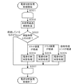
図4は、本実施形態を示す画像形成装置の制御方法を説明するフローチャートである。なお、本処理は、画像形成装置が例えば印刷処理中であったり、ユーザがユーザインタフェース部を直前まで操作していたりする場合には実行されず、使用されていない状態である間隔、例えば5秒おきなどで定期的に実行する。この処理中にユーザの操作があったり、リモートでジョブが実行されたりした場合には処理を中断終了する。なお、各ステップは、CPU13がハードディスク装置14に記憶された制御プログラムを実行することで実現される。また、本処理は前記中断終了がない限りCPU13がS301からS307までを繰り返し実行する。以下、画像形成装置の各構成要素ごとに電源供給、切断を比較的短時間で繰り返すような制御が抑制されることで、消耗部品の動作品質低下を未然に防止する制御について詳述する。また、各処理手段に対応づけて記憶されたそれぞれの保証時間を参照して、CPU13が各処理手段への電力供給を維持する制御について説明する。なお、各処理手段の機能は本実施形態では、スキャナ装置のスキャナ機能、プリンタ装置のプリント機能、画像処理ユニットの画像処理機能に対応づけられる。また、いずれを第1処理手段、第2処理手段とするかはあらかじめ設定したり、変更可能に設定したりすることは任意である。また、第1処理手段、第2処理手段に対応づける保証時間を便宜的に第1保証時間、第2保証時間と呼ぶ。
FIG. 4 is a flowchart illustrating a method for controlling the image forming apparatus according to the present exemplary embodiment. Note that this processing is not executed when the image forming apparatus is performing printing processing, for example, or when the user operates the user interface unit until just before, for example, an interval that is not used, for example, 5 seconds. Execute regularly at intervals. If there is a user operation during this process, or if a job is executed remotely, the process is terminated. Each step is realized by the
S302において、本処理の実行が開始されてからの経過時間を取得する。経過時間は絶対時刻である必要はないため、本実施形態ではCPU13内にある図示しない内部カウンタレジスタ等を用いる。もちろん絶対時刻でも同等の処理は可能である。
S303では、CPU13が取得した経過時間と、画像形成装置を構成する各構成要素の保証時間とを比較する。ここで、経過時間とは、操作要求がない状態からの経過時間をいう。各構成要素毎の保証時間はメモリ15に、図2に示した最低保障時間203として内部で保持されており、スキャナ装置2の場合は300秒、プリンタ装置の場合は360秒、画像処理装置の場合は5秒である。
S302で。取得した経過時間がスキャナ装置2の保証時間を経過しているとCPU13が判断した場合、S304に進み、スキャナ装置2の電源切断処理判定を行う。これの詳しい説明は後述する。
In S302, the elapsed time from the start of execution of this process is acquired. Since the elapsed time does not need to be an absolute time, an internal counter register (not shown) in the
In S303, the elapsed time acquired by the
In S302. When the
同様に、S303において、プリンタ装置の保証時間を経過しているとCPU13が判断した場合にはS305に、画像処理装置5の保証時間を経過しているとCPU13が判断した場合にはS306へ進む。
一方、いずれの保証時間も経過していないとCPU13が判断した場合にはS307へ進み、S301からS307の繰り返し処理を引き続き実行する。
Similarly, in S303, if the
On the other hand, when the
図5は、本実施形態を示す画像形成装置の制御方法を説明するフローチャートである。本例は、図2に示したCPU13が実行する図4のS304、S305、S306にある電源切断判定処理について詳しく記述したものである。
本処理は図4のS303において、ユーザ操作やジョブ実行が無く、保証時間が経過している場合に実行されるものである。
S304、S305、S306それぞれで処理内容はそれぞれで同一であり、処理中に参照するテーブルの位置と、実際に電源の操作を行うときのスイッチが異なるだけである。
FIG. 5 is a flowchart illustrating a method for controlling the image forming apparatus according to the present exemplary embodiment. This example describes in detail the power-off determination process in S304, S305, and S306 of FIG. 4 executed by the
This processing is executed when there is no user operation or job execution and the guarantee time has passed in S303 of FIG.
The processing contents in S304, S305, and S306 are the same, and only the position of the table that is referred to during the processing and the switch when actually operating the power supply are different.
例として、スキャナ装置2の電源切断判定処理(S304に対する図4)について説明する。
S401において、CPU13は、画像形成装置が現在ユーザによって選択されている機能の種類を取得する。この選択されている機能とは、コピー機能やFAX機能などのことであり、以後コピー機能が選択されていると仮定する。
S402において、CPU13は、前出の選択されている機能に対応するスキャナ装置2の電源状態を、図2に示すテーブルを参照し電源状態をどのように変化させるべきなのかを判定する。
As an example, the power-off determination process (FIG. 4 for S304) of the
In step S <b> 401, the
In S402, the
コピー機能選択状態204では、スキャナ装置2の各機能に対する電源状態202は「ON」であると内部管理されているため、S401での判定結果から、電源切断判定処理はそのまま電源状態を変更させること無く、本処理を終了する。この時の画像形成装置全体の電力状態を図にしたものが図6である。
In the copy
次に、S401において、選択された機能がボックス機能選択状態205の場合の電源切断判定処理について説明する。
S402において、選択された機能がボックス機能選択状態205のスキャナ装置2の各機能に対する電源状態202は「OFF」であると内部管理されているため、CPU13は、S401での判定結果から、電源切断判定処理はS403へ制御を移し、電源切断処理を行う。この時にスキャナ装置2内部に備わっている、図1に示したスイッチ32が「OFF」になり、スキャナ装置2の電源が切断される。この時の画像形成装置全体の電力状態を図にしたものが図7である。また、FAX機能選択時および、送信機能選択時において、CPU13が図5に示したS402の判断で、「OFF」である場合は、図8に示すように、プリンタ装置4への電源が切断される。
Next, the power-off determination process when the selected function is the box
In S402, since the selected function is internally managed that the
以上、図4、図5のフローチャートにあるような制御をCPU13が実行することで、画像形成装置は一定時間利用がない時に、画像形成装置の各構成要素ごとに保証時間を経過していた場合に限り、個別に電源切断が行えるようになる。
図9は、図1に示した画像形成装置の電源状態を説明するタイミングチャートである。本例では、図4,図5に示した制御による画像形成装置の各構成要素ごとの電源状態の変化を示す。
図9において、横軸は、時間経過を示し、(1)から(6)までがユーザの操作タイミングを示している。As described above, when the
FIG. 9 is a timing chart for explaining the power supply state of the image forming apparatus shown in FIG. In this example, a change in the power supply state for each component of the image forming apparatus by the control shown in FIGS. 4 and 5 is shown.
In FIG. 9, the horizontal axis indicates the passage of time, and (1) to (6) indicate the operation timing of the user.
図2からも分かる通り、コピー機能とFAX機能とではスキャナ装置2の電源状態がO N状態であることが求められる。そのため、FAX機能の選択後に最低保証時間内(例え ばFAX機能選択から10秒経過後)にコピー機能を選択してもスキャナ装置2の電源状 態はON状態のまま変化しない。一方、プリンタ装置4の電源状態はOFFからONに変 化する。また、画像処理装置5はプリンタ装置4に比べて保証時間が短いため、電源が早く切断されるよう制御される。そのため、例えばFAX機能選択から10秒経過後にコピ ー機能を選択すると、FAX機能選択の5秒後にOFFになった画像処理装置5がコピー 機能選択時に再びONになる。
また、短時間の間に機能選択が繰り返し行われるようなユーザ操作がなされても、CPU13が実行する保証時間との比較処理S303があるため、保証時間内に収まっている場合には、電源切断処理が行われず電源状態が維持される。例えば、コピー機能が選択さ れてから保証時間内にFAX機能が選択された場合、FAX機能ではプリンタ装置4を使 わない(OFF)が、保証時間が終わるまではプリンタ装置4の電源状態をOFFにしな い。これにより消耗部品の耐久性を低下させることを防いでいる。
以上処理により、ユーザが実行した機能を選択することで、本実施形態における電源供給制御が実行されると、画像形成装置の各構成要素ごとに電源供給、切断を比較的短時間で繰り返すような制御が抑制され、消耗部品の動作品質低下を未然に防止することが可能になる。
これらにより、低消費電力化と装置の寿命の両立をバランスよく実現し、使用者の利便性が大きく向上する。As can be seen from Figure 2, it is required that the copy function and the FAX function is a power state O N status of the
Further, even if a user operation such as function selection are repeated during a short time is made, because of the comparison processing S303 for the guarantee time CPU13 performs, if they fall within the warranty period, the power-off No processing is performed and the power supply state is maintained. For example, when the copy function is FAX function is selected within the assurance time since the selected, not adversely using the
When the power supply control in this embodiment is executed by selecting the function executed by the user through the above processing, power supply and disconnection are repeated in a relatively short time for each component of the image forming apparatus. Control is suppressed, and it is possible to prevent the deterioration of the operation quality of the consumable parts.
As a result, a balance between low power consumption and the life of the apparatus is realized in a balanced manner, and the convenience for the user is greatly improved.
本発明の各工程は、ネットワーク又は各種記憶媒体を介して取得したソフトウエア(プログラム)をパソコン(コンピュータ)等の処理装置(CPU、プロセッサ)にて実行することでも実現できる。 Each process of the present invention can also be realized by executing software (program) acquired via a network or various storage media by a processing device (CPU, processor) such as a personal computer (computer).
本発明は上記実施形態に限定されるものではなく、本発明の趣旨に基づき種々の変形(各実施形態の有機的な組合せを含む)が可能であり、それらを本発明の範囲から除外するものではない。 The present invention is not limited to the above embodiment, and various modifications (including organic combinations of the embodiments) are possible based on the spirit of the present invention, and these are excluded from the scope of the present invention. is not.
1 画像形成装置
2 スキャナ装置
3 コントローラ
4 プリンタ装置
5 画像処理装置
32、33、34 スイッチ
DESCRIPTION OF
Claims (17)
原稿の画像を読み取る読取手段と、
前記印刷手段及び前記読取手段に電力を供給する電力供給手段と、
第1保証時間と、前記第1保証時間よりも短い第2保証時間とを記憶する記憶手段と、前記読取手段が原稿の画像を読み取り且つ前記印刷手段が前記読取手段によって読み取られた原稿の画像に基づいて用紙に画像を印刷するコピー処理を実行し、前記コピー処理に ともない計時し、前記計時が前記第2保証時間を経過したことに基づき前記電力供給手段 による前記読取手段への電力供給を停止させ、前記計時が前記第1保証時間を経過したこ とに基づき前記電力供給手段による前記印刷手段への電力供給を停止させる制御手段と、を備えることを特徴とする印刷装置。Printing means for printing an image on paper;
Reading means for reading an image of a document;
Power supply means for supplying power to the printing means and the reading means;
Storage means for storing a first guarantee time and a second guarantee time shorter than the first guarantee time; an image of the document read by the reading means by the reading means and the reading means by the reading means; A copy process for printing an image on a sheet based on the timing of the measurement , timing the copy process, and supplying the power to the reading unit by the power supply unit based on the elapsed time of the second guaranteed time. is stopped, the printing apparatus characterized in that the time measurement and a control unit that causes stopping power supply to said printing means by said power supply means based on the this has elapsed the first guarantee time.
原稿の画像を読み取る読取手段と、
前記印刷手段及び前記読取手段に電力を供給する電力供給手段と、
第1保証時間と、前記第1保証時間よりも短い第2保証時間とを記憶する記憶手段と、前記読取手段が原稿の画像を読み取り且つ前記印刷手段が前記読取手段によって読み取られた原稿の画像に基づいて用紙に画像を印刷するコピー機能がユーザによって選択されたことに基づいて前記印刷手段及び前記読取手段への電力供給を前記電力供給手段に実行さ せ、前記電力供給にともない計時し、前記計時が前記第2保証時間を経過したことに基づ き前記電力供給手段による前記読取手段への電力供給を停止させ、前記計時が前記第1保証時間を経過したことに基づき前記電力供給手段による前記印刷手段への電力供給を停止 させる制御手段と、を備えることを特徴とする印刷装置。 Printing means for printing an image on paper;
Reading means for reading an image of a document;
Power supply means for supplying power to the printing means and the reading means;
First guarantee time and the first guarantee timeShorter thanThe user has a storage function for storing the second guaranteed time, and a copy function for reading the image of the document by the reading unit and for printing the image on the paper by the printing unit based on the image of the document read by the reading unit. The printing means and the reading means based on the selectionPower supply to the power supply means Set,The time is measured with the power supply, and the time measurement is based on the elapse of the second guaranteed time. Stop the power supply to the reading means by the power supply means,The first guaranteed timeThePassedOn the basis of the power supply meansStop power supply to the printing means MakeAnd a control unit.
Priority Applications (3)
| Application Number | Priority Date | Filing Date | Title |
|---|---|---|---|
| JP2013044574A JP6218396B2 (en) | 2013-03-06 | 2013-03-06 | Printing device |
| US14/192,535 US9001353B2 (en) | 2013-03-06 | 2014-02-27 | Image forming apparatus, control method for image forming apparatus, and program configured to control power supply to components based on guaranteed time intervals |
| US14/638,456 US9247091B2 (en) | 2013-03-06 | 2015-03-04 | Image forming apparatus, control method for image forming apparatus, and program that stop supply of power to a printer unit and supply of power to a scanner unit based on elapsed times |
Applications Claiming Priority (1)
| Application Number | Priority Date | Filing Date | Title |
|---|---|---|---|
| JP2013044574A JP6218396B2 (en) | 2013-03-06 | 2013-03-06 | Printing device |
Publications (3)
| Publication Number | Publication Date |
|---|---|
| JP2014175722A JP2014175722A (en) | 2014-09-22 |
| JP2014175722A5 JP2014175722A5 (en) | 2016-04-21 |
| JP6218396B2 true JP6218396B2 (en) | 2017-10-25 |
Family
ID=51487479
Family Applications (1)
| Application Number | Title | Priority Date | Filing Date |
|---|---|---|---|
| JP2013044574A Expired - Fee Related JP6218396B2 (en) | 2013-03-06 | 2013-03-06 | Printing device |
Country Status (2)
| Country | Link |
|---|---|
| US (2) | US9001353B2 (en) |
| JP (1) | JP6218396B2 (en) |
Families Citing this family (2)
| Publication number | Priority date | Publication date | Assignee | Title |
|---|---|---|---|---|
| JP6296729B2 (en) * | 2013-09-05 | 2018-03-20 | キヤノン株式会社 | Printing apparatus, printing apparatus control method, and printing apparatus power control method |
| JP2015089673A (en) * | 2013-11-07 | 2015-05-11 | キヤノン株式会社 | Image formation apparatus |
Family Cites Families (11)
| Publication number | Priority date | Publication date | Assignee | Title |
|---|---|---|---|---|
| JP2001201986A (en) | 2000-01-21 | 2001-07-27 | Ricoh Co Ltd | Image forming device and power saving mode controlling method of image forming device |
| CA2441899C (en) * | 2000-11-11 | 2006-01-24 | Minebea Co. Ltd. | Power converter |
| US7227652B2 (en) * | 2002-10-17 | 2007-06-05 | Lexmark International, Inc. | Switching power supply, method of operation and device-and-power-supply assembly |
| JP2006227691A (en) * | 2005-02-15 | 2006-08-31 | Canon Inc | Input/output system, power control method, computer-readable storage medium with program stored therein, and program |
| JP4752787B2 (en) * | 2007-02-15 | 2011-08-17 | 日本電気株式会社 | Disk array device, power control method and power control program used for the disk array device |
| US7787796B2 (en) * | 2007-04-17 | 2010-08-31 | Kabushiki Kaisha Toshiba | Power saving system for image forming apparatus and image forming apparatus operable in power saving modes |
| US20100053706A1 (en) * | 2008-08-28 | 2010-03-04 | Eastman Kodak Company | Detection of open scanner lid |
| JP2011098561A (en) * | 2009-10-05 | 2011-05-19 | Seiko Epson Corp | Controller for image processor |
| JP2011097315A (en) * | 2009-10-29 | 2011-05-12 | Murata Machinery Ltd | Image processing apparatus |
| JP4992985B2 (en) * | 2010-01-18 | 2012-08-08 | コニカミノルタビジネステクノロジーズ株式会社 | Image forming apparatus, image forming apparatus control method, and image forming apparatus control program |
| JP5748544B2 (en) * | 2011-04-25 | 2015-07-15 | キヤノン株式会社 | Image forming apparatus, control method therefor, and program |
-
2013
- 2013-03-06 JP JP2013044574A patent/JP6218396B2/en not_active Expired - Fee Related
-
2014
- 2014-02-27 US US14/192,535 patent/US9001353B2/en not_active Expired - Fee Related
-
2015
- 2015-03-04 US US14/638,456 patent/US9247091B2/en not_active Expired - Fee Related
Also Published As
| Publication number | Publication date |
|---|---|
| US20150181067A1 (en) | 2015-06-25 |
| US20140253948A1 (en) | 2014-09-11 |
| US9247091B2 (en) | 2016-01-26 |
| US9001353B2 (en) | 2015-04-07 |
| JP2014175722A (en) | 2014-09-22 |
Similar Documents
| Publication | Publication Date | Title |
|---|---|---|
| JP4671413B2 (en) | Image processing apparatus and image processing method | |
| JP7214518B2 (en) | Information processing device control method and program | |
| WO2011155274A1 (en) | Image formation system and image formation device | |
| JP6571908B2 (en) | Printing apparatus and printing apparatus control method | |
| JP6127682B2 (en) | Processing control device, image processing device | |
| JP2016103704A (en) | Image forming apparatus, control method of image forming apparatus, and program | |
| JP2008003863A (en) | Network device and network system | |
| JP5882255B2 (en) | Image forming apparatus and image forming method | |
| JP6218396B2 (en) | Printing device | |
| US20150192889A1 (en) | Image forming apparatus, control method and program | |
| JP2016015696A (en) | Image forming apparatus, control method of image forming apparatus, and program | |
| JP6282097B2 (en) | Information processing apparatus, information processing apparatus control method, and program | |
| JP5866276B2 (en) | Power management system | |
| US9380175B2 (en) | Image forming apparatus, control method of image forming apparatus, and computer-readable storage medium | |
| JP2019037003A (en) | Image forming apparatus and method for controlling the same | |
| JP4730510B2 (en) | Image forming apparatus | |
| JP5279642B2 (en) | Power saving mode return control device, image forming apparatus, and power saving mode return control method | |
| JP2015170002A (en) | Image forming apparatus, control method of image forming apparatus, and program | |
| JP2011109595A (en) | Image forming apparatus | |
| JP2007049368A (en) | Image processing apparatus, method for retrieving operation guide history, and program to be executed | |
| JP6222488B2 (en) | Job processing device and its program. | |
| JP6444474B2 (en) | Image forming apparatus, control method therefor, and program | |
| JP6477757B2 (en) | Image forming system | |
| JP6235884B2 (en) | Image forming apparatus, control method therefor, program, and storage medium | |
| JP2012222620A (en) | Image formation system |
Legal Events
| Date | Code | Title | Description |
|---|---|---|---|
| A521 | Written amendment |
Free format text: JAPANESE INTERMEDIATE CODE: A523 Effective date: 20160304 |
|
| A621 | Written request for application examination |
Free format text: JAPANESE INTERMEDIATE CODE: A621 Effective date: 20160304 |
|
| RD03 | Notification of appointment of power of attorney |
Free format text: JAPANESE INTERMEDIATE CODE: A7423 Effective date: 20160304 |
|
| A977 | Report on retrieval |
Free format text: JAPANESE INTERMEDIATE CODE: A971007 Effective date: 20161125 |
|
| A131 | Notification of reasons for refusal |
Free format text: JAPANESE INTERMEDIATE CODE: A131 Effective date: 20170105 |
|
| A521 | Written amendment |
Free format text: JAPANESE INTERMEDIATE CODE: A523 Effective date: 20170303 |
|
| TRDD | Decision of grant or rejection written | ||
| A01 | Written decision to grant a patent or to grant a registration (utility model) |
Free format text: JAPANESE INTERMEDIATE CODE: A01 Effective date: 20170829 |
|
| A61 | First payment of annual fees (during grant procedure) |
Free format text: JAPANESE INTERMEDIATE CODE: A61 Effective date: 20170926 |
|
| R151 | Written notification of patent or utility model registration |
Ref document number: 6218396 Country of ref document: JP Free format text: JAPANESE INTERMEDIATE CODE: R151 |
|
| LAPS | Cancellation because of no payment of annual fees |