JP6211925B2 - System and method for providing an IV set of closed and ventilating hazardous drugs - Google Patents
System and method for providing an IV set of closed and ventilating hazardous drugs Download PDFInfo
- Publication number
- JP6211925B2 JP6211925B2 JP2013509081A JP2013509081A JP6211925B2 JP 6211925 B2 JP6211925 B2 JP 6211925B2 JP 2013509081 A JP2013509081 A JP 2013509081A JP 2013509081 A JP2013509081 A JP 2013509081A JP 6211925 B2 JP6211925 B2 JP 6211925B2
- Authority
- JP
- Japan
- Prior art keywords
- reservoir
- drip chamber
- fluid
- priming
- membrane
- Prior art date
- Legal status (The legal status is an assumption and is not a legal conclusion. Google has not performed a legal analysis and makes no representation as to the accuracy of the status listed.)
- Active
Links
Images


Classifications
-
- A—HUMAN NECESSITIES
- A61—MEDICAL OR VETERINARY SCIENCE; HYGIENE
- A61M—DEVICES FOR INTRODUCING MEDIA INTO, OR ONTO, THE BODY; DEVICES FOR TRANSDUCING BODY MEDIA OR FOR TAKING MEDIA FROM THE BODY; DEVICES FOR PRODUCING OR ENDING SLEEP OR STUPOR
- A61M5/00—Devices for bringing media into the body in a subcutaneous, intra-vascular or intramuscular way; Accessories therefor, e.g. filling or cleaning devices, arm-rests
- A61M5/14—Infusion devices, e.g. infusing by gravity; Blood infusion; Accessories therefor
- A61M5/162—Needle sets, i.e. connections by puncture between reservoir and tube ; Connections between reservoir and tube
-
- A—HUMAN NECESSITIES
- A61—MEDICAL OR VETERINARY SCIENCE; HYGIENE
- A61M—DEVICES FOR INTRODUCING MEDIA INTO, OR ONTO, THE BODY; DEVICES FOR TRANSDUCING BODY MEDIA OR FOR TAKING MEDIA FROM THE BODY; DEVICES FOR PRODUCING OR ENDING SLEEP OR STUPOR
- A61M5/00—Devices for bringing media into the body in a subcutaneous, intra-vascular or intramuscular way; Accessories therefor, e.g. filling or cleaning devices, arm-rests
- A61M5/14—Infusion devices, e.g. infusing by gravity; Blood infusion; Accessories therefor
- A61M5/1411—Drip chambers
-
- A—HUMAN NECESSITIES
- A61—MEDICAL OR VETERINARY SCIENCE; HYGIENE
- A61M—DEVICES FOR INTRODUCING MEDIA INTO, OR ONTO, THE BODY; DEVICES FOR TRANSDUCING BODY MEDIA OR FOR TAKING MEDIA FROM THE BODY; DEVICES FOR PRODUCING OR ENDING SLEEP OR STUPOR
- A61M39/00—Tubes, tube connectors, tube couplings, valves, access sites or the like, specially adapted for medical use
- A61M39/20—Closure caps or plugs for connectors or open ends of tubes
-
- A—HUMAN NECESSITIES
- A61—MEDICAL OR VETERINARY SCIENCE; HYGIENE
- A61M—DEVICES FOR INTRODUCING MEDIA INTO, OR ONTO, THE BODY; DEVICES FOR TRANSDUCING BODY MEDIA OR FOR TAKING MEDIA FROM THE BODY; DEVICES FOR PRODUCING OR ENDING SLEEP OR STUPOR
- A61M5/00—Devices for bringing media into the body in a subcutaneous, intra-vascular or intramuscular way; Accessories therefor, e.g. filling or cleaning devices, arm-rests
- A61M5/14—Infusion devices, e.g. infusing by gravity; Blood infusion; Accessories therefor
- A61M5/165—Filtering accessories, e.g. blood filters, filters for infusion liquids
-
- A—HUMAN NECESSITIES
- A61—MEDICAL OR VETERINARY SCIENCE; HYGIENE
- A61M—DEVICES FOR INTRODUCING MEDIA INTO, OR ONTO, THE BODY; DEVICES FOR TRANSDUCING BODY MEDIA OR FOR TAKING MEDIA FROM THE BODY; DEVICES FOR PRODUCING OR ENDING SLEEP OR STUPOR
- A61M5/00—Devices for bringing media into the body in a subcutaneous, intra-vascular or intramuscular way; Accessories therefor, e.g. filling or cleaning devices, arm-rests
- A61M5/36—Devices for bringing media into the body in a subcutaneous, intra-vascular or intramuscular way; Accessories therefor, e.g. filling or cleaning devices, arm-rests with means for eliminating or preventing injection or infusion of air into body
- A61M5/38—Devices for bringing media into the body in a subcutaneous, intra-vascular or intramuscular way; Accessories therefor, e.g. filling or cleaning devices, arm-rests with means for eliminating or preventing injection or infusion of air into body using hydrophilic or hydrophobic filters
-
- A—HUMAN NECESSITIES
- A61—MEDICAL OR VETERINARY SCIENCE; HYGIENE
- A61M—DEVICES FOR INTRODUCING MEDIA INTO, OR ONTO, THE BODY; DEVICES FOR TRANSDUCING BODY MEDIA OR FOR TAKING MEDIA FROM THE BODY; DEVICES FOR PRODUCING OR ENDING SLEEP OR STUPOR
- A61M5/00—Devices for bringing media into the body in a subcutaneous, intra-vascular or intramuscular way; Accessories therefor, e.g. filling or cleaning devices, arm-rests
- A61M5/14—Infusion devices, e.g. infusing by gravity; Blood infusion; Accessories therefor
- A61M2005/1401—Functional features
- A61M2005/1402—Priming
-
- A—HUMAN NECESSITIES
- A61—MEDICAL OR VETERINARY SCIENCE; HYGIENE
- A61M—DEVICES FOR INTRODUCING MEDIA INTO, OR ONTO, THE BODY; DEVICES FOR TRANSDUCING BODY MEDIA OR FOR TAKING MEDIA FROM THE BODY; DEVICES FOR PRODUCING OR ENDING SLEEP OR STUPOR
- A61M2202/00—Special media to be introduced, removed or treated
- A61M2202/04—Liquids
- A61M2202/0468—Liquids non-physiological
- A61M2202/049—Toxic
Landscapes
- Health & Medical Sciences (AREA)
- Heart & Thoracic Surgery (AREA)
- Animal Behavior & Ethology (AREA)
- General Health & Medical Sciences (AREA)
- Biomedical Technology (AREA)
- Engineering & Computer Science (AREA)
- Hematology (AREA)
- Life Sciences & Earth Sciences (AREA)
- Veterinary Medicine (AREA)
- Anesthesiology (AREA)
- Public Health (AREA)
- Vascular Medicine (AREA)
- Pulmonology (AREA)
- Emergency Medicine (AREA)
- Infusion, Injection, And Reservoir Apparatuses (AREA)
- Packages (AREA)
Description
本発明は、医療および注入療法の分野において一般的に用いられる静脈内(IV)投与セットを危険有害性薬物または化学物質でプライミングする(priming)ためのシステムおよび方法に関する。 The present invention relates to systems and methods for priming intravenous (IV) dosing sets commonly used in the fields of medical and infusion therapy with hazardous drugs or chemicals.
IV投与セットは通常、血液、薬剤、栄養補給物もしくは溶液などの流体を患者に送出する、またはそれらを患者から回収するために用いられる。医学の一部の領域では、疾病および病気の治療に毒性のある化学療法剤など危険な化学物質の注入が必要である。危険有害性薬物は通常IVバッグなどの液溜めに加えられ、次いで、患者用導管および静脈針を介して患者に投与される。危険な溶液を患者に投与する前に、患者への空気の注入を防止するために、患者用導管内の空気を除去しなければならない。 IV administration sets are typically used to deliver fluids such as blood, medications, nutritional supplements or solutions to a patient or to retrieve them from a patient. Some areas of medicine require the injection of dangerous chemicals such as toxic chemotherapeutic agents for the treatment of diseases and illnesses. Hazardous drugs are usually added to a reservoir, such as an IV bag, and then administered to the patient via a patient conduit and a venous needle. Prior to administering the hazardous solution to the patient, the air in the patient conduit must be removed to prevent air from being injected into the patient.
標準的なプライミング処置は、IV投与セットのドリップチャンバ部を圧縮し、液溜めからの危険有害性薬物の流れを開始することを伴う。流れが開始されると、危険有害性薬物は引き続き患者用導管を通り、それによって導管内の空気を移動させる。しかしながら、導管から空気を移動させることに加えて、危険有害性薬物の流れは、危険有害性薬物から発生した危険な蒸気も移動させる。移動した危険な蒸気への暴露によって、病気、めまい、嘔気、嘔吐、発作、意識不明、また死亡さえも引き起こされる恐れがある。さらに臨床医は、危険有害性薬物が患者用導管を出ないことを保証するために、準備的な作業工程(プライミング工程)を注意深く監視しなければならない。危険有害性薬物に直接曝されることによって、前述の副作用が引き起こされる恐れもある。 A standard priming procedure involves compressing the drip chamber portion of the IV dosing set and initiating the flow of the hazardous drug from the reservoir. When flow is initiated, the hazardous drug continues through the patient conduit, thereby moving the air in the conduit. However, in addition to moving air from the conduit, the hazardous drug stream also moves dangerous vapors generated from the hazardous drug. Exposure to transferred dangerous vapors can cause illness, dizziness, nausea, vomiting, seizures, unconsciousness, and even death. In addition, the clinician must carefully monitor the preparatory work process (priming process) to ensure that hazardous drugs do not exit the patient conduit. Direct exposure to hazardous drugs can also cause the aforementioned side effects.
したがって、現在でも危険有害性薬物と共に使用するIV投与セットをプライミングするために用いられる技術は存在するが、依然として課題がある。したがって、現在の技術を高め、またはさらに他の技術と置き換えることが、当技術分野における進歩になるであろう。 Thus, there are still techniques that can be used to prime IV administration sets for use with hazardous drugs, but there are still challenges. Therefore, it would be an advance in the art to enhance current technology or even replace other technology.
本発明は、静脈内(IV)投与セットを危険有害性薬物または化学物質でプライミングする際に使用するための閉鎖式の通気システムを提供するシステムおよび方法に関する。具体的には、本発明は、IV送出システム内の危険有害性薬物または蒸気への暴露を最小限に抑えるように設計された様々なポートおよび流路を組み込んだIV送出システムに関する。 The present invention relates to a system and method for providing a closed ventilation system for use in priming an intravenous (IV) administration set with a hazardous drug or chemical. In particular, the present invention relates to IV delivery systems that incorporate various ports and flow paths designed to minimize exposure to hazardous drugs or vapors within the IV delivery system.
IV送出システムは一般に、ドリップチャンバをIVバッグなどの液溜めに取り付けるためのカップリングアッセンブリーを含む。いくつかの実施例において、カップリングアッセンブリーは、液溜めと送出システムのドリップチャンバとの間に流体連通をもたらす第1の流路を含む。他の実施例において、カップリングアッセンブリーは、液溜めと外部の取付口(access port)との間に流体連通をもたらす第2の流路をさらに含む。外部の取付口は、カップリングアッセンブリーまたはドリップチャンバの外側表面に結合され、液溜めへの直接的な接続を行う。いくつかの実施例において、取付口は、危険有害性薬物を第2の流路を介して液溜めに送出するために、注射器によって接続される。他の実施例において、取付口は、第2の流路を密閉するために弁またはセプタムをさらに含む。 IV delivery systems generally include a coupling assembly for attaching the drip chamber to a reservoir such as an IV bag. In some embodiments, the coupling assembly includes a first flow path that provides fluid communication between the sump and the drip chamber of the delivery system. In another embodiment, the coupling assembly further includes a second flow path that provides fluid communication between the sump and an external access port. An external fitting is coupled to the outer surface of the coupling assembly or drip chamber and provides a direct connection to the reservoir. In some embodiments, the attachment port is connected by a syringe to deliver the hazardous drug to the reservoir via the second flow path. In other embodiments, the attachment port further includes a valve or septum to seal the second flow path.
IVセットは、第1の流路の出口端にしっかり取り付けられたドリップチャンバをさらに含む。ドリップチャンバは、一般に、液溜めから流体を受け入れるように構成された閉鎖式の容器を含む。本発明のいくつかの実施例において、ドリップチャンバは、外部のプライミングポート(priming port)をさらに含む。プライミングポートはドリップチャンバの外側表面に結合され、ドリップチャンバと流体連通する。いくつかの実施例では、プライミングポートを介してドリップチャンバにプライミング溶液が注入される。注入されたプライミング溶液は、注入前に患者用導管をプライミングするのに有用であることがあるか、または注入処置後に残留する危険有害性薬物を除去するために患者用導管をどっと流す(flushing)際に有用であることがある。 The IV set further includes a drip chamber securely attached to the outlet end of the first flow path. A drip chamber generally includes a closed container configured to receive fluid from a reservoir. In some embodiments of the present invention, the drip chamber further includes an external priming port. The priming port is coupled to the outer surface of the drip chamber and is in fluid communication with the drip chamber. In some embodiments, a priming solution is injected into the drip chamber via a priming port. The infused priming solution may be useful for priming the patient conduit prior to infusion, or flushing the patient conduit to remove hazardous drug remaining after the infusion procedure. Sometimes useful.
本発明の他の実施において、IV投与セットのドリップチャンバおよび患者用導管は、液溜め内に含まれる危険有害性薬物でプライミングされる。いくつかの実施例では、患者用導管の終端部をカップリングアッセンブリーの取付口に挿入することによって準備的な作業工程中の望ましくない危険有害性薬物への暴露が防止される。したがって、患者用導管をプライミングするとき、危険なガスが取付口を介して液溜めの中に放出される。こうして、危険な微粒子への暴露が回避される。 In another implementation of the present invention, the drip chamber and patient conduit of the IV administration set are primed with a hazardous drug contained within the reservoir. In some embodiments, the end of the patient conduit is inserted into the coupling assembly fitting to prevent exposure to undesirable hazardous drugs during preparatory work steps. Thus, when priming the patient conduit, dangerous gases are released into the sump through the attachment port. Thus, exposure to dangerous particulates is avoided.
本発明のいくつかの実施例では、IV送出システム内に残留する危険有害性薬物が、フラッシュポート(flush port)を介してシステムからどっと流される。フラッシュポートは、一般に、患者の注入部位から上流のIV送出システムの外部表面に位置決めされる。いくつかの実施例では、プライミング液またはフラッシング流体をIV送出システム内に送出するためにフラッシュポートに注射器または他の送出装置が結合される。したがって、プライミング液は、残留する危険有害性薬物を送出システムから患者にどっと流される。さらに、いくつかの実施例では、準備的な作業工程の間、患者用導管の終端部を容器または濾過システムに挿入することによって、望ましくない危険有害性薬物への暴露が防止される。 In some embodiments of the present invention, hazardous drugs remaining in the IV delivery system are flushed out of the system via a flush port. The flush port is generally positioned on the external surface of the IV delivery system upstream from the patient's injection site. In some embodiments, a syringe or other delivery device is coupled to the flash port for delivering priming fluid or flushing fluid into the IV delivery system. Thus, the priming fluid is flushed from the delivery system to the patient with the remaining hazardous drug. Further, in some embodiments, exposure to undesirable hazardous drugs is prevented by inserting the end of the patient conduit into a container or filtration system during the preparatory work process.
本発明に関する前述のおよび他の特徴および利点が得られる方法が容易に理解されるように添付図面に示すその具体的な実施例を参照することによりこれまで簡単に説明した本発明についてより詳細な説明を行う。これらの図面は本発明の典型的な実施例を示すにすぎず、したがって、本発明の範囲を限定するとみなされるものではない。 For a better understanding of the manner in which the foregoing and other features and advantages of the present invention are obtained, reference may be made to the detailed description of the invention as briefly described above with reference to specific embodiments thereof as illustrated in the accompanying drawings. Give an explanation. These drawings depict only typical embodiments of the invention and are therefore not to be considered as limiting the scope of the invention.
本発明の現在好ましい実施例は、図面を参照することによって最も良く理解され、図中、同一の参照数字は、同一、即ち、機能上同様な要素を示す。本発明の構成要素は、本明細書において全体として説明され図面において図示されるように様々な異なる構成で配置され、設計され得ることが容易に理解されるであろう。したがって、図に示されるように、以下のより詳細な説明は、請求の範囲に記載の本発明の範囲を限定するものではなく、本発明の現在好ましい実施例の一例にすぎない。 The presently preferred embodiments of the invention are best understood by referring to the drawings, wherein like reference numerals indicate identical, or functionally similar, elements. It will be readily appreciated that the components of the present invention can be arranged and designed in a variety of different configurations as generally described herein and illustrated in the drawings. Accordingly, as shown in the figures, the following more detailed description is merely an example of the presently preferred embodiments of the invention, not limiting the scope of the invention as recited in the claims.
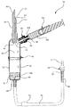
そこで図1を参照すると、(IV)静脈内送出システム10の実施が示されている。IV送出システム10のいくつかの実施例は、図3に示すように、液溜め12に挿入するように構成されたスパイク30を有するカップリングアッセンブリー20を含む。カップリングアッセンブリー20のいくつかの実施は、ポリスチレン、ポリエステルまたはポリプロピレンなどの硬質のポリマー物質からなる。スパイク部材30のいくつかの実施例は、カップリングアッセンブリー20の液溜め12への挿入を助けるための角をそいだ端面32をさらに含む。
Referring now to FIG. 1, (IV) an implementation of an
いくつかの実施例において、カップリングアッセンブリー20は第1の流路60をさらに含む。第1の流路60は、結合された液溜め12とIV送出システム10のドリップチャンバ40との間に液路をもたらす。第1の流路60は、入力端62および出口端64を含む。図3を参照すると、入力端62は、液溜め12の中に位置決めされ、出口端64は、ドリップチャンバ40の入力端46に結合される。第1の流路60の出口端64は、液溜め12からの流体16が出口端64を介してドリップチャンバ40内に溜められるように、ドリップチャンバ40に隣接して位置決めされる。いくつかの実施例において、出口端64は、流体16がドリップチャンバ40内に溜められる前に液滴18を形成可能とする先細の開口部をさらに含む。
In some embodiments, the
ドリップチャンバ40は、全体として、第1の流路60の出口端64から分配される流
体16を受け入れるように構成される。上述したように、出口端64は、流体16が出口
端64を出るとき、流体16が液滴18を形成可能となるように構成される。いくつかの
実施例において、ドリップチャンバ40は、下部の軟質部72に密閉した形で結合された
上部の硬質部71を有する略円筒形である。いくつかの実施例では、ドリップチャンバ4
0の軟質部72の操作によって、液溜め12からドリップチャンバ40内への流体、即ち
、危険有害性薬物16の流れが開始される。この方法は、まず、スパイク30を密閉され
た液溜め12に挿入し、ローラークランプ(roller clamp)52または類似
のクランプデバイスによって患者用導管50を塞ぐことにより、システム10を密閉され
ることを必要とする。ドリップチャンバ40の軟質部72を圧縮および解放することによ
って、真空が、ドリップチャンバ40内に作られる。この圧縮が、ドリップチャンバ40
内の空気を液溜め12の中に移動させ、したがって、ドリップチャンバ40内に負圧、即
ち、真空を作る。ドリップチャンバ内の負圧は、危険有害性薬物16を液溜め12からドリップチャンバ40に引き込み、ドリップチャンバ40内に第2の液溜め42を従来通り、形成する。ローラークランプ52が一旦、解放されたならば、危険有害性流体16は、重力によって液溜め12から流れ続ける。当業者は、重力供給方法または蠕動ポンプを利用する方法などを含めたシステムにより、他の方法が、危険な流体16の流れを開始するために使用可能であることを理解するであろう。
The
The operation of the zero
The air inside moves into the
再び、図1を参照すると、本発明のいくつかの実施例は、自己密封式のプライミング/フラッシングポート44をさらに含む。プライミング/フラッシングポート44は、ドリップチャンバ40の外面に結合される。いくつかの実施例では、プライミング/フラッシングポート44は、第2の液溜め42の上方に位置決めされる。他の実施例では、プライミング/フラッシングポート44は、ドリップチャンバ40の第2の液溜め42の部分に隣接して、即ち、その液溜め42の内側に位置決めされる。フラッシング/プライミングポート44は、ドリップチャンバ40の内部に流体連通し、プライミング/フラッシング溶液160を直接的にドリップチャンバ40に送出するように構成された注射器180、または他の装置を、互換可能に受け入れるように設計される。いくつかの実施例において、プライミング/フラッシングポート44は、注射器180の先端部182を受け入れるための開口部190を含む。プライミング/フラッシングポート44は、先端182を開口部190に挿入することによって開放状態に付勢される、弁、即ち、スプリットセプタム184をさらに含む。先端部182を挿入する前、弁、即ち、セプタム184が気密シールを形成し、それによって、ドリップチャンバ40内およびIV送出システム10の残りの部分における内部の圧力を維持する。
Referring again to FIG. 1, some embodiments of the present invention further include a self-sealing priming / flushing
いくつかの実施例において、ドリップチャンバ40および患者用導管50は、プライミング/フラッシングポート44を介してプライミング溶液160で予め準備的な作業が行われる。そこで図2を参照すると、ドリップチャンバ40は、プライミング液160を収容する注射器180によって、プライミング/フラッシングポート44を介して利用される。いくつかの実施例において、プライミング液160は、塩化ナトリウムまたはぶどう糖のような危険有害性ではない添加剤を含む水の無菌溶液である。ドリップチャンバ40および患者用導管50を準備的に作業する工程は、これらの構成要素から空気を抜き、それによって、注入工程中、患者に空気が注入されないようにする。
In some embodiments,
いくつかの実施例において、IV送出システム10は、ドリップチャンバ40内に配設された膜66をさらに含む。膜66は、空気がドリップチャンバ40を出て患者用導管50に入るのを防止するように構成される。したがって、膜66は、そうでなければドリップチャンバ40から流出して患者用導管50に入る場合がある気泡を捕えるためのバブルトラップ(bubble trap)として働く。図1乃至図3に示すように、ドリップチャンバ40は、患者用導管50に接続される。導管50は、ドリップチャンバ40および第1の液溜め12から患者100まで流体160を運ぶために使用される管からなる。
In some embodiments, the
膜66は、ドリップチャンバの出口端48を完全に覆うように、ドリップチャンバ40
の下部に位置決めされる。膜66をチャンバの出口端48を完全に覆うように位置決めす
ることによって、プライミング液160が膜66を通過するとき、空気が膜66と出口端
48との間で捕えられることが妨げられる。さらに、いくつかの実施例において、膜66
は、流体160と強く相互作用するように構成された親水性物質からなり、それによって、膜66内の流体160を捕える。いくつかの実施例において、膜66は、ポリテトラフルオロエチレン、親水性ナイロン、親水性ポリプロピレン、親水性ポリエーテルスルホン、または上述の物質で被覆された不織材料のうちの少なくとも1つからなる。流体160がドリップチャンバ40から膜66を通って流れるとき、膜66内に捕えられた流体160は、流入する流体160によって移動され、移動された流体160は、患者用導管50に押し込まれる。しかしながら、ドリップチャンバ40が枯れる場合、または、ドリップチャンバ40からの流体160の供給が枯渇する場合、膜66内の流体160が保持され、患者用導管50の中の流れが、なくなる。したがって、ドリップチャンバ40内の空気が、膜66を通過し患者用導管50に入ることが防止される。
The
Positioned at the bottom of the. Positioning the
It consists configured hydrophilic substance to interact strongly with the fluid 160, thereby capturing the fluid 160 in the
いくつかの実施例では、ローラークランプ52または他のクランプデバイス、ならびに、流量制御用プラグ、即ち、ベントメンブレン58が、患者用導管50に取り付けられ得る。例えば、いくつかの実施例において、膜58は、ルアーコネクタ(luer connector)またはフリクションインターフェース(friction interface)のような結合手段を介して患者用導管50に結合される。クランプ52によって、ドリップチャンバ40を出る流体160の流れが、制御および停止可能とされる。いくつかの実施例において、クランプは、流体160が比速度(specific rate)で流れ得るように予め設定される。他の実施例において、クランプ52は、流体160の流量を制限するように構成されたポンプまたは他の装置(不図示)と組み合わせて使用される。
In some embodiments, a
ベントメンブレン58は、全体として、様々な機能をもたらすために必要な物質、または、物質の組み合わせからなる。いくつかの実施例において、ベントメンブレン58は、静脈内の管系50の終端部54に直接的に結合される。他の実施例において、端部54は、ケーシングのようなベントメンブレン58を受け入れるための凹部、または、他のフィーチャ(feature)を含むように構成される。他の実施例では、図1Bに示すように、ダストキャップ56が、ベントメンブレン58を含むように変更される。ダストキャップ56は、膜58を保持し、しかも、膜58の中の空気の通過が可能にするように構成された複数の通気孔110を含むこともできる。
The
ベントメンブレン58は、IV送出システム10が必要とされるような様々な機能をもたらすように構成され得る。例えば、いくつかの実施例において、ベントメンブレン58は、端部54を外部の汚染物質から保護するための汚染物質用フィルタとして設けられる。他の実施例において、ベントメンブレン58は、送出システム内の空気の排出を可能にし、しかも、流体160の通過を妨げるように構成された疎水性のエアーフィルタとして設けられる。
The
いくつかの実施例において、ベントメンブレン58は、ポリテトラフルオロエチレンなどの多孔性物質からなり、空気の通過を可能にし、しかも、流体、危険有害性の溶液または危険有害性の溶質のようなより大きい分子の通過を妨げることができるように、大きさを定められ構成された複数の孔を有する。他の実施例において、ベントメンブレン58は、約0.1ミクロンから0.5ミクロンまでの大きさの複数の細孔を含み、それによって、空気が複数の細孔を通過することを可能にし、しかも、システム10内の流体、および、より大きいエーロゾル化された粒子または危険有害性薬物の分子の通過を妨げることができる。したがって、システム10の準備的な作業中、患者用導管50内の空気は、流体160および危険有害性ガス24は導管50内に保持される間、ベントメンブレン58を通って導管50を出て行くことが可能になる。その準備的な作業後、クランプ52は、導管50を塞ぐように係合される。一旦、塞がれたならば、導管50の終端部54が、カテーテル102または二次的なIVライン(不図示)を介して患者に結合される。
In some embodiments, the
いくつかの実施例において、ベントメンブレン58は、準備的な作業工程の間、プラグ58と接触するエーロゾル化した、即ち、ガス状の危険有害性薬物の通過可能性を最小限に抑えるように設計された360°の膜を備える。したがって、ベントメンブレン58は、患者用導管50内の毒性のない空気の通過を可能にするように構成され、しかも、より大きい毒性のある分子の通過を制限するための構造的または化学的な機能を含む。これらの機能は、そのような制限をもたらすことができる如何なる技術または装置を含んでもよい。
In some embodiments, the
例えば、いくつかの実施例において、ベントメンブレン58の材料は、ポリテトラフルオロエチレン、親水性ナイロン、親水性ポリプロピレン、親水性ポリエーテルスルホン、または上述の材料で被覆された不織材料のうちの少なくとも1つからなる。ベントメンブレン58は、上述したように限られた多孔度をさらに含み、それによって、より大きい分子の通過を制限する。他の実施例において、ベントメンブレン58は、危険有害性薬物の分子に結合し、それによってプラグ58内の危険な分子を隔離する活性炭のような触媒からなる。他の実施例において、ベントメンブレン58は、PTFEと活性炭または木炭の交互層からなる合成物からなる。
For example, in some embodiments, the material of the
導管50を通る流体160の流量は、導管内の空気がベントメンブレン58を通って流れることができる速度によって決定される。したがって、導管50を通る流体160の流れは、プラグ58の孔の数および大きさを増減することによって調節することができる。例えば、いくつかの実施例において、ベントメンブレン58の流量は、孔の直径を大きくすること、または孔の数を増やすことによって高められる。他の実施例において、ベントメンブレン58の流量は、孔の直径を小さくすること、または孔の数を減らすことによって低下される。
The flow rate of
いくつかの実施例において、ベントメンブレン58を通る空気の流量は、膜66を通る流体160の流量以下になるように構成される。したがって、いくつかの実施例において、膜66の流量と、ベントメンブレン58の流量とは、システム10を通る流体160が適切な気泡を含まない流れに確実になるように一致される。いくつかの実施例において、膜66およびベントメンブレン58の流量は、流体160が、空気がベントメンブレン58を通って出る速度よりわずかに遅い速度で膜66を通って流れることを確実にするように釣り合わされる。したがって、図2乃至図4に示すように、流体160は、第2の液溜め42にプール76を形成する。
In some embodiments, the air flow rate through the
流体160のプール76は、ドリップチャンバ40から導管50を通って流れる、連続的で気泡を含まない流体源を形成し、導管50に閉じ込められた空気を移動させる。他の実施例では、導管50を通る流体160の流速が最適な流速まで遅くなるように、ベントメンブレン58の流速は、膜66の流速より遅くなるように構成される。いくつかの実施例において、最適な流速は、準備的な作業工程の間、流体160が効率的かつ完全に導管50内の空気を移動させる速度である。
A
膜66およびベントメンブレン58を組み込むように構成されたその実施例において、システム10の準備的な作業工程は、従来のようなローラークランプ52または任意の類似のクランプデバイスの使用が不要である。むしろ、膜66とベントメンブレン58との組み合わせによって、システム10の自動的な準備的な作業を可能にする。具体的には、プライミング液160がドリップチャンバ40に注入されたならば、流体160は、ベントメンブレン58に達するまで膜66および導管50を通って自動的に流れる。いくつかの実施例において、ドリップチャンバ40は、通気孔74をさらに含み、それによってドリップチャンバ40内の負圧が、流体160が膜66を通って自動的に流れることが可能になるように等しくされる。
In its embodiment configured to incorporate the
ドリップチャンバ40に対する通気孔74の位置は、第2の液溜め42の高さを決める
ように選択される。したがって、流体16がドリップチャンバ40に流入するとき、流体
16の高さが、位置決めされた通気孔74の高さを超えることを妨げられる。第2の液溜
め42の高さが位置決めされた通気孔74の高さを超える場合、通気孔74は、流体16
で塞がれ、それによって、逃がすこと、および/または、ドリップチャンバ40内の圧力
を等しくすることが妨げられる。したがって、正圧がドリップチャンバ40内で高まり、
第1の液溜め12からの流体の流れを妨げる。流体16が解放され、即ち、患者用導管5
0に流入するとき、第2の液溜め42の高さは通気孔74の高さより低い位置まで戻され
、それによって、通気孔74がドリップチャンバ40内の正圧を解放することが可能にな
る。ドリップチャンバ40内の圧力が等しくなるとき、第1の液溜め12からの流体の流
れが、再開する。
The position of the
To prevent escape and / or equalization of the pressure in the
The flow of fluid from the first
When entering 0, the height of the
いくつかの実施例において、通気孔74は、ドリップチャンバ内のエーロゾル化した危
険なガス24を閉じ込めるか、または無害にするように構成されたフィルタ(図示せず)
をさらに備える。他の実施例において、通気孔74は、危険なガス24をドリップチャン
バ40から直接第1の液溜め12の中に逃がす導管(図示せず)をさらに備える。例えば
いくつかの実施例において、カップリングアッセンブリー20は、第1の液溜め12に結
合された平行な空気の流路(図示せず)をさらに含むことができる。さらに、いくつかの
実施例において、通気孔74は、望ましくない危険なガス24の環境への暴露を防止する
ために、危険なガス24をドリップチャンバ40からドラフト(図示せず)または他の容
器の中に逃がす導管(図示せず)を備える。
In some embodiments, the
Is further provided. In other embodiments, vent 74 further comprises a conduit (not shown) that allows
流体160がベントメンブレン58と接触すると、流体160の流れが停止され、それによって膜66を通る流体の流れを終了させる。ベントメンブレン58を取り外す前、ローラークランプ52が、患者用導管50のプライミングされた状態を維持するようにすることができる。この自己プライミング用の構成により、はじくこと、またはシステム10の構成要素の他の手動操作によって気泡を手で移動させることを必要とせずに、システム内の空気の効率的な除去処理が行われる。
When the fluid 160 comes into contact with the
いくつかの実施例において、端部54は、ルアー装置を端部54に結合するとベントメンブレン58が自動的に無効になり、それによって、導管を通る流体の流れを再開するように構成される。図1Cを参照すると、ルアーによって作動されるベントメンブレン158の代表的な実施例が示されている。当業者には、この実施例が、ルアーによって作動される膜を設けることができる、多くの方法および設計の1つを示すにすぎないことが理解されるであろう。一般に、端部54は、患者用導管50の一端に挿入した形で結合されるプラグ120を備える。プラグ120と導管50の間の開口部が、その2つの構成要素間の流体連通を可能にする。プラグ120のフランジ付きの部分130が、ルアー装置(図示せず)に関連付けられたカプラ(図示せず)を固定するための手段として設けられる。プラグ120の内部の空洞140が、ベントメンブレン158およびバイアス手段152を収容するように構成される。いくつかの実施例において、バイアス手段152は、コイルばねまたは穿孔されたエラストマー材料を含む。他の実施例では、ベントメンブレン158の一部がバイアス機能をもたらすように変更される。
In some embodiments, the
いくつかの実施例では、空洞140の第1の端部が、ベントメンブレン158の外径より小さい内径を有する保持用の隆起部142を備える。空洞140は、バイアス手段152を支持するために、段付きの表面144を有する第2の端部をさらに備える。したがって、膜158およびバイアス手段152は、空洞140内で保持用の隆起部142と段付きの表面144との間に介在した形で位置決めされる。構成されるとき、バイアス手段152は、膜158を保持用の隆起部142に接するように位置決めし、その結果、膜158と保持用の隆起部142の間にシール154が形成される。したがって、準備的な作業工程の間、システム10内の空気がシステム10から膜158を通して放出されるが、膜158および/またはシール154の物理的特性によって流体の通過が妨げられる。
In some embodiments, the first end of the
図1Dを参照すると、ルアー装置170を端部54に結合すると、シール154が無効になる。ルアー装置170は、膜158を作動させることが可能な構成を有する任意の装置を含むことができる。いくつかの実施例において、ルアー装置170は、プラグ120に結合するための機構174を有する本体172を備える。ルアー装置170は、カテーテルまたはカテーテルの管系210などの下流の装置と流体連通する内部の空洞182をさらに備える。ルアー装置170は、部分的にプラグ120に挿入し、膜158に接触するように構成されたプローブ部176をさらに備える。プローブ部176と膜158の間で接触すると、膜158は、シール154が無効になるように再び位置決めされる。プローブ部176の中に配置された複数の孔またはポート178は、流体がカテーテルの管系210に流入することが可能になるように、プラグ120とルアー装置170の内部の空洞182との間に流体連通をもたらす。
Referring to FIG. 1D, when the
次に図3を参照すると、ドリップチャンバ40および患者用導管50のプライミング後に、カップリングアッセンブリー20のスパイク30が第1の液溜め12に結合される。いくつかの実施例において、第1の液溜め12は、危険な化学物質または薬物16を含むIVバッグである。他の実施例において、第1の液溜め12は、IVボトルまたは他の類似のリザーバデバイスである。液溜め12は一般に、セプタム36または穴をあけることが可能な膜を含み、それを通して、スパイク30が適合した形で挿入される。挿入されると、図4に示すように、ローラークランプ52が解放され、危険有害性薬物16がカップリングアッセンブリー20を通って流れ、ドリップチャンバ40および患者用導管50に入ることが可能になる。剛性または半剛性のIVボトルを組み込んだそうした実施例の場合には、ドリップチャンバ40の一部が、通気孔74をさらに含むことができる。いくつかの実施例において、通気孔74は、危険有害性薬物16がシステム10を通って移動するとき、IV送出システム10内の、エーロゾル化したまたはガス24の形の危険有害性薬物の通過のためのポテンシャルを最小限に抑えるように設計されたフィルタを含む。
Referring now to FIG. 3, after priming the
次に図4を参照すると、危険有害性薬物16を注入した後、フラッシング流体160が、自己密封式のプライミング/フラッシングポート44を介してドリップチャンバ40に加えられる。いくつかの実施例において、フラッシング流体160は、プライミング溶液160と同一である。他の実施例において、フラッシング流体160は、補助的な危険のない薬物である。フラッシング流体160は、残りの危険有害性薬物16を患者に押し込み、それによって、確実に薬物16の注入を完了させる。フラッシング流体160の注入はさらに、残留する危険有害性薬物16のため、IV送出システム10のカテーテル102の部分を清浄化する、または汚染を除去するように働く。十分な体積のフラッシング流体160を注入した後、技師または患者100を危険有害性薬物16に曝すことなく、カテーテル102を挿入部位106から安全に取り外すことができる。
Referring now to FIG. 4, after infusing the
本発明のいくつかの実施例において、IV送出システム10は、図5に示すように、複
数の流路60および70を有するカップリングアッセンブリー120を含む。上述したよ
うに、第1の流路60は、結合された液溜め12とIV送出システム10のドリップチャ
ンバ40との間に、液路を形成する。いくつかの実施例において、カップリングアッセンブリー120は、自己密封式の取付口26と結合した液溜め12との間に液路を形成する第2の流路70をさらに備える。第2の流路70は、入力端34および出口端38を含み、入力端34は取付口26の内側部分に結合され、出口端38は液溜め12の流体160と流体連通する。いくつかの実施例において、第1の流路60および第2の流路70は、流路60と70の両方の長さにわたる共通の分割壁22を共有する。いくつかの実施例において、第2の流路70は管(図示せず)であり、管の壁が第1の流路60を第2の流路70から隔てる。
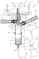
In some embodiments of the present invention, the
いくつかの実施例において、第2の流路70は取付口26をさらに含む。取付口26はカップリングアッセンブリー120の外面に結合され、第2の流路70と流体連通する。取付口26は、危険有害性薬物16を第2の流路70を介して液溜め12に送出するように構成された注射器80または他の送出装置を、適合した形で受け入れるように設計される。いくつかの実施例において、取付口26は、注射器80を受け入れ、非可逆的に保持するように設計される。他の実施例において、取付口26は、注射器80の一部に配置された適合する1組のねじ山(図示せず)を受け入れるように構成された1組のねじ山(図示せず)を備える。他の実施例において、取付口26および注射器80は、ルアーロック式のカップリングアッセンブリーを介して互いに結合される。
In some embodiments, the
取付口26は一般に、注射器80の先端部82を受け入れるための開口部90を含む。取付口26は、先端82を開口部90に挿入することによって開放される弁またはスプリットセプタム84さらに含む。先端部82を挿入する前、セプタム84を偏倚させて閉鎖および密閉された構成にし、それによって、プライミング液160が出口端38を介して第2の流路70の中に漏出することを防止する。いくつかの実施例において、キャリア流体は、液溜め12のプライミング液160である。先端部82および開口部90を可逆的に結合した、または可逆的に組み合わせたそうした実施例の場合、先端82を開口部90から取り外すと、セプタム84が閉鎖および密閉された構成に戻り、それによって、流体が第2の流路70から漏出することを防止する。
The
本発明のいくつかの実施例では、危険有害性薬物16を取付口26を介して注入する前に、ドリップチャンバ40および患者用導管50がプライミング液160でプライミングされる。システム10をプライミングするプロセスはまず、カップリングアッセンブリー120のスパイク部30を、プライミング液160を含む第1の液溜め12に挿入することが必要である。自己プライミング用の構成として構成されたそうした実施例の場合、第1の液溜め12のプライミング液160は、ドリップチャンバ40および患者用導管50に自動的に流入し、それによって第2の液溜め42を形成し、さらには導管50内の空気を移動させる。
In some embodiments of the present invention,
いくつかの実施例において、システム10はベントメンブレン58を除くように構成され、膜66のみを備える。こうした実施例の場合、システム10をプライミングするプロセスはまず、ローラークランプ52または類似のクランプデバイスによって患者用導管50を塞ぐことを含む。塞がれた後、カップリングアッセンブリー120のスパイク部30が第1の液溜め12に挿入される。次いで、従来通り、ドリップチャンバ40の軟質部72が圧縮されるか、あるいは流体160を第1の流路60を介してドリップチャンバ40に引き込むように操作される。第2の液溜め42が形成されると、ローラークランプ52が解放され、プライミング液160によって第1のリザーバ12から患者用導管50を通る流れが再開され、導管50内の空気を除去する。
In some embodiments, the
他の実施例において、システム10は膜66を除くように構成され、ベントメンブレン58のみを備える。こうした実施例の場合、システム10をプライミングするプロセスは、患者用導管50をローラークランプ52によって塞ぐ前に、カップリングアッセンブリー120のスパイク部30を第1の液溜め12に挿入することを含む。プライミング液160は、第1の液溜め12からドリップチャンバ40および患者用導管50に自由に流入する。プライミング液160がベントメンブレン58に達すると、流体の流れが止まり、患者用導管50がローラークランプ52によって塞がれる。この時点において、システム10はプライミング液160によって完全にプライミングされ、その結果、患者用導管50内の空気が完全に移動し、除去される。いくつかの実施例では、ダストキャップ56および隣接するベントメンブレン58が、患者用導管50の終端部54から取り外され、患者用導管50は補助的な患者用導管(図示せず)に結合されるか、または図6に示すように静脈内カテーテル102に結合される。
In other embodiments, the
次に図6を参照すると、危険有害性薬物16が、取付口26および注射器80を介して第1の液溜め12に注入される。いくつかの実施例では、注射器80の先端部82が、先端部82がセプタム84を開放位置に偏倚させるように、取付口26の開口部90に挿入される。次いで注射器80が作動され、危険有害性薬物16を第1の液溜め12に供給する。第1の液溜めの危険有害性薬物16およびプライミング液160が混合され、プライミング液160内に危険有害性薬物16の所望の濃度をもたらす。次いで、ローラークランプ52が解放され、システム10を通り、結合されたカテーテル102を介して患者100に流入する流体16の流れを再開する。
Referring now to FIG. 6, the
いくつかの実施例において、患者用導管50はフラッシュポート86をさらに含む。フラッシュポート86は一般に、患者用導管50の外面に結合されたアダプタを備える。フラッシュポート86は、注射器180の先端部182を適合した形で受け入れるように構成された開口部88を含む。いくつかの実施例において、開口部88は、注射器の先端部182を開口部88に注入することによって開放位置に偏倚させることができる、セプタム84をさらに備える。他の実施例において、開口部88は、注射器の先端182を開口部88に注入することによって開放位置に対して無効になる、穴をあけることが可能な膜をさらに備える。フラッシュポート86の他の実施例は、図7に示すように、注射器180が患者用導管50に流動する形で接続することを可能にする弁または他の装置を含む。
In some embodiments, the
次に図7を参照すると、危険有害性薬物16の注入後のIVシステムが示されている。いくつかの実施例では、注入処置の後、危険な蒸気24および使用されていない危険有害性薬物が、第1の液溜め12の中に残る。他の実施例では、注射器80および取付口26が、注射器80を取り外すことができないように非可逆的に組み合わされ、その結果、望ましくない残りの危険有害性薬物16への暴露が起こる。流れ止め(anti−run)の乾燥膜66を備えるそうした実施例の場合、危険有害性薬物16は、ドリップチャンバ40から完全になくなるが、膜66を通り過ぎて流れ出ることはない。むしろ、危険有害性薬物16は膜66の中に留まり、空気が患者用導管50に注入されるのを防止する。結果として、患者用導管50を通る危険有害性薬物16の流れが止まり、患者用導管50は危険有害性薬物16で満たされる。さらに、カテーテル102の挿入された部分は、依然として危険有害性薬物16で汚染された状態のままである。したがって、いくつかの実施例では、患者用導管50の外面がフラッシュポート86を含むように変更される。フラッシュポート86は、カテーテル102を患者100から取り外す前にIV送出システム10のカテーテル部102をすすぐために、プライミング液またはフラッシング流体160を含む注射器180を適合する形で受け入れるように構成される。
Referring now to FIG. 7, the IV system after injection of the
患者用導管50にフラッシングポート86を介してどっと流すためのプロセスはまず、患者用導管50をローラークランプ52によって塞ぐことが必要である。いくつかの実施例において、ローラークランプ52は、患者用導管50の外面上の、ドリップチャンバ40とフラッシングポート86の間に介在した形で位置決めされる。患者用導管50が塞がれた後、注射器180がフラッシングポート86の開口部88に挿入され、注射器180と患者用導管50内の流体16との間に流体連通をもたらす。次いで、注射器180が作動され、フラッシング流体160を患者用導管50およびカテーテル102を介して患者に注入および注入する。フラッシング流体160を注入するプロセスにおいて、患者用導管50の下流部分、ならびにカテーテル102の挿入された部分は、フラッシング流体160で完全にすすがれる。したがって、カテーテル102の挿入された部分は、危険有害性薬物16による汚染が除去され、危険有害性薬物16への暴露なしに安全に取り外すことが可能になる。次いで、注射器80および180に結合されたIV送出システム10、ならびに残りの危険有害性薬物16を、危険有害性薬物16に対する局所暴露または吸入による暴露なしに安全に処理することができる。
The process for flushing the
危険有害性薬物16を患者100に安全に投与するIV送出システム10を提供するために、本発明の様々な特徴を組み合わせて使用することができる。例えば図8を参照すると、プライミング/フラッシングポート44と取付口26の両方を組み込んだIV送出システム10が提供される。いくつかの実施例では、第1の流路60および第2の流路70を有するカップリングアッセンブリー120が提供される。第1の流路60は、カップリングアッセンブリー120と取り付けられたドリップチャンバ40との間に流体連通をもたらす。いくつかの実施例では、カップリングアッセンブリー120のスパイク部30が、IVバッグまたはIVボトルなどの液溜め12に挿入される。したがって、カップリングアッセンブリー120の第1の流路60は、図9に示すように、流体160が液溜め12からドリップチャンバ40に流入することを可能にする導管を形成する。
Various features of the present invention can be used in combination to provide an
上述したように、第2の流路70はカップリングアッセンブリー120の一部を形成し、全体的に第1の流体60に平行に延びる。第2の流路70は取付口26をさらに備え、それによって、流体16が外部から第2の流路70に注入される。いくつかの実施例では、第2の流路の開口部または出口端38が、カップリングアッセンブリー120のスパイク部30の上に配置される。したがって、図10に示すように、カップリングアッセンブリー120のスパイク部30が第1の液溜め12に挿入されているとき、流体16を第2の流路70を介して液溜め12に注入することができる。いくつかの実施例では、取付口26の開口部90が、注射器80または他の類似の流体送出装置を適合した形で受け入れるように構成される。他の実施例において、開口部90は、注射器80および取付口26を可逆的に組み合わせるための機能を含むように変更される。さらに、いくつかの実施例において、開口部90は、注射器80および取付口26を受け入れ、永久的に組み合わせるための1つまたは複数の機能を含むように変更される。
As described above, the
いくつかの実施例では、ドリップチャンバ40の一部が、プライミング/フラッシングポート44を含むように変更される。プライミング/フラッシングポート44は、前述の図1〜4に関連して上述したように、ドリップチャンバ40への直接的な接続を行う。したがって、いくつかの実施例では、図8に示すように、ドリップチャンバ40および患者用導管50は、注射器180およびプライミング/フラッシングポート44を介して、プライミング溶液160でプライミングされる。他の実施例では、図9に示すように、ドリップチャンバ40および患者用導管50は、カップリングアッセンブリー120のスパイク部30を、プライミング液160を含む第1の液溜め12に挿入することによってプライミングされる。ベントメンブレン58を実装するそうした実施例の場合、プライミング液160はドリップチャンバ40に自動的に流入し、患者用導管50を通り、その中に存在する空気を移動させる。
In some embodiments, a portion of the
図8および9のプライミング処置の後、図10に示すように、患者用導管50がローラ
ークランプ52によって塞がれ、危険有害性薬物16が、第2の流路70および取付口2
6を介して第1の液溜め12に注入される。一般的には、注射器80の先端部が取付口2
6の開口部90に挿入され、セプタム84を開放状態に偏倚させて、注射器80と第2の
流路70の間の流体連通を開始する。次いで、注射器80内の高濃度の危険有害性薬物1
6が、第2の流路70を介して第1の液溜め12に注入される。次いで、危険有害性薬物
16が第1の液溜め12のプライミング液160と混合され、所望の濃度の危険有害性薬
物16の溶液をもたらす。次いで、ローラークランプ52が解放され、希釈された危険有
害性薬物16がドリップチャンバ40および患者用導管50に流入することが可能になる。いくつかの実施例では、ベントメンブレン58およびダストキャップ56が静脈内カテーテル102と交換され、危険有害性薬物16の患者100への静脈内注入が可能になる。
After the priming procedure of FIGS. 8 and 9, as shown in FIG. 10, the
6 and injected into the first
6, the
6 is injected into the first
図10の注入処置の後、図11に示すように、フラッシング流体160をプライミング/フラッシングポート44を介してドリップチャンバに加えることによって、ドリップチャンバ40および患者用導管50内の残りの危険有害性薬物16が患者100にどっと流される。いくつかの実施例において、フラッシング流体160は、図9におけるプライミング液160と同一である。他の実施例において、フラッシング流体160は、補助的な危険のない薬物である。フラッシング流体160は、ドリップチャンバ40、患者用導管50およびカテーテル102を通って流れるため、残留する危険有害性薬物16が患者100に注入される。さらに、構成要素40、50および102は危険有害性薬物16による汚染が除去され、それによって、薬物16または危険な蒸気24に対する局所暴露なまたは吸入による暴露の可能性を伴わずに、カテーテル102を患者100から安全に取り外すことが可能になる。カテーテル102を取り外した後、IV送出システム10、残留する薬物16、ならびに結合された注射器80および180が適当に処理される。
After the infusion procedure of FIG. 10, the remaining hazardous drug in
本発明のいくつかの実施例において、IV送出は、流れ止めの乾燥膜66もベントメンブレン58も含まない。こうした実施例の場合、臨床医は従来通り、ドリップチャンバ40の軟質部72を圧縮することによって、液溜め12からの流れを開始する。他の実施例において、ドリップチャンバ40および患者用導管50は、製造業者によってプライミング液16で予めプライミングされる。カップリングアッセンブリー20または120を第1の液溜め12に取り付ける前に、患者用導管50がクランプ52によって塞がれる。次いで、危険有害性薬物16が取付口26を介して液溜め12に注入され、クランプ52を解放することによって、システム10を通る流れが開始される。いくつかの実施例において、クランプ12は、患者用導管50を通る所望の流量を可能にするように選択的に調整することができる。他の実施例では、第2の流路70の中に残る微量の薬物16が、注射器80を繰り返し作動させることによって第1の液溜め12の中に洗い流される。
In some embodiments of the present invention, IV delivery does not include the non-flowing
一般的なやり方は、臨床医に引き渡す前に、液溜め12に危険有害性薬物16を予め注入することである。危険有害性薬物16を予め注入することは、一般的には、ドラフトの下でまたは十分に換気された領域で薬剤師または他の技師によって行われる。予め注入することによって、臨床医が高濃度の危険有害性薬物を扱う必要がなくなり、さらに適切な投薬が保証される。予め注入されたリザーバは、患者に投与するために臨床医に引き渡される。本発明のいくつかの実施例は、予め注入されたリザーバ、ならびに複数のまたは連続的に接続された液溜めと共に用いられる。
A common practice is to pre-inject the
いくつかの実施例では、図12に示すように、第2の流路70を用いて危険な蒸気24
を第1の液溜め12の中に逃がす。例えばいくつかの実施例では、予め注入された液溜め
12からの危険有害性薬物16によって導管50を直接プライミングすることによって、
患者用導管50内の空気が除去される。危険有害性薬物16がドリップチャンバ40を出
て、患者用導管50を通って進むため、危険有害性薬物16からの危険な蒸気24が導管
50を通って押し動かされる。流れ制約デバイス58は、液体の危険有害性薬物16が導
管50を出るのを防止するが、装置58は、危険な蒸気24が容易に通過できるように二
重に設計される。したがって準備的な作業工程の間、臨床医は、望ましくないことに危険
な蒸気24に曝される恐れがある。
In some embodiments, as shown in FIG. 12, the
Is allowed to escape into the
Air in the
したがって、本発明のいくつかの実施例では、IVセット10を危険有害性薬物16でプライミングする前に、患者用導管50の終端部54が取付口26に適合した形で挿入される。終端部が取付口26に結合されると、ローラークランプ52が解放され、危険有害性薬物16のドリップチャンバ40への流入を開始する。危険有害性薬物16が患者用導管50を通って移動するため、危険な蒸気24が、導管50から第2の流路70を介して液溜め12の中に移される。したがって、患者用導管50から捕えられた空気が除去され、危険有害性薬物16からの危険な蒸気24がガス化されて液溜め12に入り、システム10に含まれるようになる。この準備的な作業工程によって完全なプライミングが保証されると同時に、安全ではない危険有害性薬物16および蒸気24の臨床医への暴露が防止される。
Thus, in some embodiments of the present invention, prior to priming the IV set 10 with the
準備的な作業工程の後、導管50が再びローラークランプ52で塞がれ、終端部54が
取付口26から取り外される。次いで臨床医は、カテーテル102を介して導管50を患
者100に取り付けることが可能になるように、ダストキャップ56およびベントメンブ
レン58を取り外すことができる。いくつかの実施例において、ダストキャップ56は弁
装置をさらに備え、それによって、カテーテル102は、ダストキャップ56またはベン
トメンブレン58を取り外すことなく、直接かつ流動する形で患者用導管50に結合され
る。他の実施例では、IVカテーテル102の一部によってベントメンブレン58に穴を
あけることが可能であり、それにより、IVカテーテル102は、流れ制御装置58を取
り外すことなく、直接かつ流動する形で患者用導管50に結合される。したがって臨床医
は、患者用導管50内の危険有害性薬物16に曝されることなく、患者用導管50を患者
100に安全に取り付けることができる。さらに、いくつかの実施例において、患者用導
管50はフラッシュポート86をさらに備え、それによって、システム10の終端部54
および結合されたカテーテル102は、患者100から取り外す前にフラッシング流体1
60でどっと流される。
After the preparatory work process, the
And the combined
It is washed away at 60 .
次に図13を参照すると、患者用導管50を危険有害性薬物16でプライミングするプロセスの間の本発明の実施が示されている。いくつかの実施例において、患者用導管50の終端部54は、準備的な作業工程の間、導管50から移動した危険な蒸気24を受け入れ、収容するように構成された容器94に結合される。容器94は、望ましくない危険な蒸気24への暴露を防止することが可能な任意の装置またはシステムを含むことができる。例えばいくつかの実施例において、容器94はタンクである。他の実施例において、容器94は、通気フードまたは濾過システムである。さらに他の実施例において、容器94は使い捨てのバッグまたはバルーンである。
Referring now to FIG. 13, the practice of the present invention during the process of priming the
いくつかの実施例において、容器94は、蒸気24を隔離するか、あるいは蒸気24と
反応してその危険性を低減する、中和剤または触媒剤をさらに備える。他の実施例では、
キャップ56またはベントメンブレン58が、臨床医を導管50内の危険な蒸気24また
は危険有害性薬物16に曝すことなく、終端部をカテーテル102または他の装置を介し
て患者100に取り付けることができるようにさらに変更される。さらに、本発明のいく
つかのドリップチャンバ40は、プライミング/フラッシングポート44を含み、それに
よって、注入処置後、患者100から患者用導管50および結合されたカテーテル102
を取り外す前に、それらの中の危険有害性薬物16がどっと流される。
In some embodiments, the
Before they are removed, the
次に図14を参照すると、危険有害性薬物16を患者用導管50を介して患者100に供給するために、主要なIVセット200が補助的なIVセット300と組み合わされる。この実施例では、補助的なIVセット300が、インライン式(inline)の取付口202を介して主要なIVセット200に結合される。インライン式の取付口202は、第2のIVセット300の危険有害性薬物16が、患者用導管50および患者100に流入することを可能にする。いくつかの実施例において、第2のIVセット300の導管ライン150は閉鎖式のルアーチップ302を含み、ルアーチップ302は、インライン式の取付口202に取り付けられると、液路を自動的に開放する。さらに、ルアーチップ302をインライン式の取付口202から取り外すと、液路は閉鎖され、ルアーチップ302は、患者用導管50を通るプライミング液160の流れによって清浄化される。いくつかの実施例において、インライン式の取付口202は、ルアーチップ302の回転するロックナットを受け入れるための1組のねじ山を含む。こうした実施例の場合、ルアーチップ302は、ロックナットをねじ山の組のまわりに締め付けると開放され、ロックナットをねじ山の組から外すと閉鎖される。他の実施例では、インライン式の取付口202の近位部を用い、完全なまたはほぼ完全な係合によってルアーチップ302を開閉する。さらに、いくつかの実施例において、ルアーチップ302は、ルアーチップ302を通る流体の流れを開閉するために、手動のスイッチまたは弁を含む。
Referring now to FIG. 14, the primary IV set 200 is combined with the auxiliary IV set 300 to deliver the
危険有害性薬物16の注入後、第2のIVセット300のローラークランプ52を作動させ、第2のIVセット300の導管ライン150を塞ぐ。次いで、患者用導管50のローラークランプ52が解放され、プライミング液160が患者用導管50を通って流れることが可能になり、残りの危険有害性薬物16を患者100にどっと流す。いくつかの実施例では、ルアーチップ302がプライミング液160によってすすがれ、危険有害性薬物16を含まなくなるように、ルアーチップ302の一部が患者用導管50の流れの経路の中に位置決めされる。他の実施例において、インライン式の取付口202は、注入後に微量の危険有害性薬物16を保持するデッドスペース(deadspace)を含む。したがって、いくつかの実施例では、第2のIVセット300の導管ライン150に、フラッシュポート86が組み込まれる。フラッシュポート86は、導管ライン150の遠位部を通してプライミング液160を注入するために、注射器によって接続される。したがって、フラッシュポート86によって、インライン式の取付口202のデッドスペースを十分にどっと流して残りの危険有害性薬物16を除くことが可能である。インライン式の取付口202および患者用導管50から危険有害性薬物を完全にどっと流した後、危険有害性薬物16への暴露なしに、カテーテル102を患者100から安全に取り外すことができる。さらに、いくつかの実施例において、インライン式の取付口202はデッドスペースのないコネクタである。例えばいくつかの実施例において、デッドスペースのないコネクタは、患者用導管50の流れの経路とルアーチップ302との間のデッドスペースを除いたものである。
After injection of the
本発明は、本明細書において広義に説明され、以下において請求される構造、方法または他の本質的な特徴から逸脱することなく、他の特定の形で具体化することが可能である。したがって、説明した実施例は、すべての点において例示的なものにすぎず、限定するものではではないとみなされたい。例えば本発明のいくつかの実施例は、IVポンプと共に使用することができる。本発明の他の実施例は、ドリップチャンバ、またはローラークランプもしくはdial−a−flowなどの流れ計量装置を使用しないように構成することができる。したがって本発明の範囲は、前述の説明ではなく、添付の特許請求の範囲によって示される。特許請求の範囲の均等物の趣旨および範囲の中に入るすべての変更が、特許請求の範囲内に包含される。 The present invention may be embodied in other specific forms without departing from the structure, method or other essential features described broadly herein and claimed below. Accordingly, the described embodiments are to be considered in all respects only as illustrative and not restrictive. For example, some embodiments of the present invention can be used with IV pumps. Other embodiments of the invention can be configured not to use a drip chamber or a flow metering device such as a roller clamp or dial-a-flow. The scope of the invention is, therefore, indicated by the appended claims rather than by the foregoing description. All changes that come within the spirit and scope of the equivalents of the claims are to be embraced within their scope.
Claims (9)
入力端および出口端を有するドリップチャンバであって、前記ドリップチャンバの前記入力端が、前記第1の液溜めからの前記流体を受け入れ、前記ドリップチャンバ内に第2の液溜めを形成するように、前記カップリングアッセンブリーの前記出口端に結合され、該ドリップチャンバが、前記第2の液溜めに隣接し、前記第2の液溜めと流体連通するように位置決めされたプライミングポートをさらに含み、前記ドリップチャンバの前記出口端が、患者用導管を受け入れるように構成されるドリップチャンバと、
前記第2の液溜めと前記ドリップチャンバの前記出口端との間に介在し位置決めされた膜であって、前記ドリップチャンバから前記ドリップチャンバの前記出口端までの空気の通過を妨げる膜と、
前記患者用導管に配置されたベントメンブレンであって、前記ベントメンブレンを通る空気の流速が前記膜を通る前記流体の流速以下となるように構成される、ベントメンブレンと、
を含む危険有害性溶液の静脈内送出のためのIV溶液送出システム。 A coupling assembly having a first flow path and a second flow path, wherein the first flow path has an input end and an outlet end, and the input end extends from the first liquid reservoir to the outlet. Configured to couple to a first reservoir to provide fluid flow to the end, the second flow path having a first end and a second end interconnected to flow. The first end is in fluid communication with the first reservoir and the second end delivers a hazardous solution to the first reservoir through the second flow path. A coupling assembly in fluid communication with a mounting port for receiving a delivery device configured to:
A drip chamber having an input end and an outlet end, wherein the input end of the drip chamber receives the fluid from the first reservoir and forms a second reservoir in the drip chamber. A priming port coupled to the outlet end of the coupling assembly, the drip chamber positioned adjacent to the second reservoir and in fluid communication with the second reservoir; A drip chamber in which the outlet end of the drip chamber is configured to receive a patient conduit;
A membrane interposed and positioned between the second reservoir and the outlet end of the drip chamber, the membrane preventing passage of air from the drip chamber to the outlet end of the drip chamber;
A vent membrane disposed in the patient conduit, wherein the vent membrane is configured such that a flow rate of air through the vent membrane is less than or equal to a flow rate of the fluid through the membrane;
IV solution delivery system for intravenous delivery of hazardous solutions comprising:
前記ドリップチャンバの前記出口端に結合された第1の端部と、
前記患者用導管を通る空気および流体の流れを制御するように構成された、流れ制御用プラグを支持する第2の端部と、
を含む請求項1に記載のシステム。 The patient conduit is
A first end coupled to the outlet end of the drip chamber;
A second end supporting a flow control plug configured to control air and fluid flow through the patient conduit;
The system of claim 1 comprising:
Applications Claiming Priority (3)
| Application Number | Priority Date | Filing Date | Title |
|---|---|---|---|
| US12/775,128 | 2010-05-06 | ||
| US12/775,128 US8366658B2 (en) | 2010-05-06 | 2010-05-06 | Systems and methods for providing a closed venting hazardous drug IV set |
| PCT/US2011/032487 WO2011139514A1 (en) | 2010-05-06 | 2011-04-14 | Systems and methods for providing a closed venting hazardous drug iv set |
Publications (3)
| Publication Number | Publication Date |
|---|---|
| JP2013525064A JP2013525064A (en) | 2013-06-20 |
| JP2013525064A5 JP2013525064A5 (en) | 2014-05-22 |
| JP6211925B2 true JP6211925B2 (en) | 2017-10-11 |
Family
ID=44626068
Family Applications (1)
| Application Number | Title | Priority Date | Filing Date |
|---|---|---|---|
| JP2013509081A Active JP6211925B2 (en) | 2010-05-06 | 2011-04-14 | System and method for providing an IV set of closed and ventilating hazardous drugs |
Country Status (8)
| Country | Link |
|---|---|
| US (2) | US8366658B2 (en) |
| EP (1) | EP2566570B1 (en) |
| JP (1) | JP6211925B2 (en) |
| CN (1) | CN102892459B (en) |
| AU (1) | AU2011248902B2 (en) |
| BR (1) | BR112012028046B1 (en) |
| ES (1) | ES2553145T3 (en) |
| WO (1) | WO2011139514A1 (en) |
Families Citing this family (77)
| Publication number | Priority date | Publication date | Assignee | Title |
|---|---|---|---|---|
| US6695817B1 (en) | 2000-07-11 | 2004-02-24 | Icu Medical, Inc. | Medical valve with positive flow characteristics |
| WO2006052655A2 (en) | 2004-11-05 | 2006-05-18 | Icu Medical, Inc. | Soft-grip medical connector |
| US7547300B2 (en) | 2006-04-12 | 2009-06-16 | Icu Medical, Inc. | Vial adaptor for regulating pressure |
| CN102131536B (en) * | 2008-07-02 | 2013-11-13 | 泰尔茂株式会社 | Connector and infusion tube set |
| WO2010022095A1 (en) | 2008-08-20 | 2010-02-25 | Icu Medical, Inc. | Anti-reflux vial adaptors |
| US9168366B2 (en) | 2008-12-19 | 2015-10-27 | Icu Medical, Inc. | Medical connector with closeable luer connector |
| US8454579B2 (en) | 2009-03-25 | 2013-06-04 | Icu Medical, Inc. | Medical connector with automatic valves and volume regulator |
| US8323249B2 (en) | 2009-08-14 | 2012-12-04 | The Regents Of The University Of Michigan | Integrated vascular delivery system |
| US9498271B2 (en) * | 2009-10-29 | 2016-11-22 | Cook Medical Technologies Llc | Coaxial needle cannula with distal spiral mixer and side ports for fluid injection |
| DE102009051945A1 (en) * | 2009-11-04 | 2011-05-05 | Fresenius Medical Care Deutschland Gmbh | Drug delivery adapter with gas barrier element for a hemodialysis tube set |
| USD644731S1 (en) | 2010-03-23 | 2011-09-06 | Icu Medical, Inc. | Medical connector |
| US8366658B2 (en) | 2010-05-06 | 2013-02-05 | Becton, Dickinson And Company | Systems and methods for providing a closed venting hazardous drug IV set |
| US8758306B2 (en) | 2010-05-17 | 2014-06-24 | Icu Medical, Inc. | Medical connectors and methods of use |
| WO2011146772A1 (en) | 2010-05-19 | 2011-11-24 | Tangent Medical Technologies Llc | Safety needle system operable with a medical device |
| WO2011146769A2 (en) | 2010-05-19 | 2011-11-24 | Tangent Medical Technologies Llc | Integrated vascular delivery system |
| AU2012296495B2 (en) | 2011-08-18 | 2016-03-10 | Icu Medical, Inc. | Pressure-regulating vial adaptors |
| WO2013036854A1 (en) | 2011-09-09 | 2013-03-14 | Icu Medical, Inc. | Medical connectors with fluid-resistant mating interfaces |
| CA2860589C (en) | 2012-01-13 | 2021-10-26 | Icu Medical, Inc. | Pressure-regulating vial adaptors and methods |
| AU2013204180B2 (en) | 2012-03-22 | 2016-07-21 | Icu Medical, Inc. | Pressure-regulating vial adaptors |
| US9302049B2 (en) * | 2012-08-20 | 2016-04-05 | Becton, Dickinson And Company | Medical devices for blood reflux prevention and methods of use |
| AU2013342123B2 (en) | 2012-11-12 | 2018-08-02 | Icu Medical, Inc. | Medical connector |
| JP6113859B2 (en) * | 2012-11-30 | 2017-04-12 | ベクトン ディキンソン アンド カンパニー リミテッド | Infusion adapter for drug delivery assembly |
| EP3552595B1 (en) | 2013-01-23 | 2023-09-13 | ICU Medical, Inc. | Pressure-regulating vial adaptors |
| US9089475B2 (en) | 2013-01-23 | 2015-07-28 | Icu Medical, Inc. | Pressure-regulating vial adaptors |
| US9555379B2 (en) * | 2013-03-13 | 2017-01-31 | Bayer Healthcare Llc | Fluid path set with turbulent mixing chamber, backflow compensator |
| US10758648B2 (en) * | 2013-03-15 | 2020-09-01 | Kci Licensing, Inc. | Vacuum cartridge with integrated valve |
| EP2968894B1 (en) | 2013-03-15 | 2017-07-19 | ICU Medical, Inc. | Medical connector |
| US20150018765A1 (en) * | 2013-07-09 | 2015-01-15 | Welford Manufacturing (M) SDN BHD | Infusion set that prevents air entry into infusion tubing |
| JP6617101B2 (en) | 2013-07-19 | 2019-12-04 | アイシーユー メディカル インコーポレイテッド | Pressure regulating fluid transfer system and method |
| WO2015034870A2 (en) * | 2013-09-03 | 2015-03-12 | Arocha Max | Double-chamber mixing syringe and method of use |
| CA2932124C (en) | 2013-12-11 | 2023-05-09 | Icu Medical, Inc. | Check valve |
| WO2015119940A1 (en) | 2014-02-04 | 2015-08-13 | Icu Medical, Inc. | Self-priming systems and methods |
| WO2015195844A1 (en) | 2014-06-20 | 2015-12-23 | Icu Medical, Inc. | Pressure-regulating vial adaptors |
| US9724464B2 (en) | 2014-06-30 | 2017-08-08 | Carefusion 303, Inc. | Passive restart Y-site |
| US9731070B2 (en) | 2014-06-30 | 2017-08-15 | Carefusion 303, Inc. | Passive start drip chamber |
| AU2015311787B2 (en) | 2014-09-04 | 2019-08-01 | Avent, Inc. | Gastric systems, apparatus, and methods for use with enteral feeding |
| USD793551S1 (en) | 2014-12-03 | 2017-08-01 | Icu Medical, Inc. | Fluid manifold |
| USD786427S1 (en) | 2014-12-03 | 2017-05-09 | Icu Medical, Inc. | Fluid manifold |
| CN104901061A (en) * | 2015-02-13 | 2015-09-09 | 深圳巴斯巴科技发展有限公司 | Novel soft-connection high-voltage connector |
| US10413662B2 (en) * | 2015-05-14 | 2019-09-17 | Carefusion 303, Inc. | Priming apparatus and method |
| WO2017042899A1 (en) | 2015-09-08 | 2017-03-16 | 株式会社コバヤシ | Infusion set |
| US10195415B2 (en) * | 2015-09-21 | 2019-02-05 | Carefusion 303, Inc. | Priming device |
| US11744935B2 (en) * | 2016-01-28 | 2023-09-05 | Deka Products Limited Partnership | Apparatus for monitoring, regulating, or controlling fluid flow |
| AU2017211855B2 (en) | 2016-01-29 | 2022-06-02 | Icu Medical, Inc. | Pressure-regulating vial adaptors |
| US10898638B2 (en) | 2016-03-03 | 2021-01-26 | Bayer Healthcare Llc | System and method for improved fluid delivery in multi-fluid injector systems |
| DK178713B1 (en) * | 2016-03-29 | 2016-11-28 | Boegh Innovation Aps | SELF-RINSE INTRAVENOUS INFUSION KIT |
| CN105797237A (en) * | 2016-05-12 | 2016-07-27 | 山东威高集团医用高分子制品股份有限公司 | Liquid medicine filter |
| WO2018064206A1 (en) | 2016-09-30 | 2018-04-05 | Icu Medical, Inc. | Pressure-regulating vial access devices and methods |
| MY189974A (en) * | 2016-11-10 | 2022-03-22 | Poly Medicure Ltd | Intravenous infusion set |
| DE102017201755A1 (en) * | 2017-02-03 | 2018-08-09 | B. Braun Melsungen Ag | Penetration part for a medical infusion system, drip chamber and infusion system |
| DE102017205250A1 (en) * | 2017-03-28 | 2018-10-04 | B. Braun Melsungen Ag | Piercing part for a medical infusion system |
| CN107198659B (en) * | 2017-07-03 | 2023-11-24 | 北京大学深圳医院 | Infusion adapter and infusion system with same |
| WO2019046299A1 (en) | 2017-08-31 | 2019-03-07 | Bayer Healthcare Llc | Fluid path impedance assessment for improving fluid delivery performance |
| CA3067625C (en) | 2017-08-31 | 2024-04-30 | Bayer Healthcare Llc | Injector pressure calibration system and method |
| EP3675930B1 (en) | 2017-08-31 | 2024-01-17 | Bayer Healthcare LLC | Method for drive member position and fluid injector system mechanical calibration |
| CN110869071B (en) | 2017-08-31 | 2023-05-02 | 拜耳医药保健有限公司 | Method of dynamic pressure control in a fluid injector system |
| EP3675927B1 (en) | 2017-08-31 | 2023-12-13 | Bayer Healthcare LLC | Fluid injector system volume compensation system and method |
| JP6850400B2 (en) | 2017-12-03 | 2021-03-31 | ウェスト ファーマ サービシーズ イスラエル リミテッド | Infusion device with telescopic bottle adapter for use with infusion container and another infusion bottle |
| CN108888829A (en) * | 2018-05-14 | 2018-11-27 | 河南兴恒医疗用品有限公司 | The disposable accurate liquid that stops filters anti-puncture no-needle transfusion device |
| USD903864S1 (en) * | 2018-06-20 | 2020-12-01 | West Pharma. Services IL, Ltd. | Medication mixing apparatus |
| CA3015070A1 (en) * | 2018-08-22 | 2020-02-22 | Duoject Medical Systems Inc. | Easy linking transfer system |
| US11550345B2 (en) | 2018-10-17 | 2023-01-10 | Pneuma Systems Corporation | Airflow-based volumetric pump |
| USD881390S1 (en) * | 2018-12-14 | 2020-04-14 | Avent, Inc. | IV spike with multi-port tubing adapter |
| USD881389S1 (en) * | 2018-12-14 | 2020-04-14 | Avent, Inc. | IV spike |
| JP1648075S (en) | 2019-01-17 | 2019-12-16 | ||
| ES2946032T3 (en) | 2019-01-31 | 2023-07-12 | West Pharma Services Il Ltd | liquid transfer device |
| JP7001838B2 (en) | 2019-04-30 | 2022-01-20 | ウェスト ファーマ サービシーズ イスラエル リミテッド | Dual lumen IV liquid transfer device with spikes |
| US11654272B2 (en) * | 2019-09-20 | 2023-05-23 | Carefusion 303, Inc. | One-time priming IV infusion extension set |
| JP2023514704A (en) | 2020-02-21 | 2023-04-07 | バイエル・ヘルスケア・エルエルシー | Fluid path connectors for medical fluid delivery |
| MX2022010694A (en) | 2020-02-28 | 2022-09-26 | Bayer Healthcare Llc | Fluid mixing set. |
| US11517668B2 (en) * | 2020-04-03 | 2022-12-06 | Carefusion 303, Inc. | Expandable drip chamber |
| EP4140521A4 (en) * | 2020-04-20 | 2023-12-27 | SK-Electronics CO., LTD. | Pressurization-type drug injector having drug exposure preventive function |
| WO2021257699A1 (en) | 2020-06-18 | 2021-12-23 | Bayer Healthcare Llc | In-line air bubble suspension apparatus for angiography injector fluid paths |
| US20210402082A1 (en) * | 2020-06-29 | 2021-12-30 | Pneuma Systems Corporation | Simplified pneumatic volumetric pump using iv drip chamber |
| USD956958S1 (en) | 2020-07-13 | 2022-07-05 | West Pharma. Services IL, Ltd. | Liquid transfer device |
| AU2021107217A4 (en) * | 2020-08-28 | 2021-12-09 | Genentech, Inc. | Point of care drug delivery apparatus and method |
| WO2022076325A1 (en) * | 2020-10-05 | 2022-04-14 | Mobile I.V. Systems, LLC | Drip chamber with automatic vent and shutoff |
Family Cites Families (20)
| Publication number | Priority date | Publication date | Assignee | Title |
|---|---|---|---|---|
| GB1182016A (en) | 1967-02-08 | 1970-02-25 | Baxter Laboratories Inc | Parenteral Administration of Liquids |
| US4013072A (en) | 1975-11-03 | 1977-03-22 | Baxter Travenol Laboratories, Inc. | Drip chamber for intravenous administration |
| US4521212A (en) | 1982-08-03 | 1985-06-04 | Baxter Travenol Laboratories, Inc. | Solution administration set |
| US4734091A (en) * | 1985-02-11 | 1988-03-29 | Atlantic Optical Systems, Inc. | Filtered manifold apparatus and method for ophthalmic irrigation |
| US4998926A (en) | 1985-12-13 | 1991-03-12 | Becton, Dickinson And Company | Parenteral fluid administration set |
| US4685912A (en) | 1986-03-05 | 1987-08-11 | Patent Research And Development Corp. | I.V. drip chamber with built-in pump activated by external means |
| US4795429A (en) | 1987-10-28 | 1989-01-03 | Feldstein Marvin A | Method and apparatus for use in the control of intravenous medication introduction |
| SE9300448L (en) | 1993-02-11 | 1994-02-07 | Gambro Dialysatoren | Drip and / or expansion chamber with built-in filter and method for making one |
| US5423346A (en) | 1994-03-03 | 1995-06-13 | Ivac Corporation | Fluid container shut off valve |
| SE509950C2 (en) * | 1995-05-02 | 1999-03-29 | Carmel Pharma Ab | Device for the administration of toxic liquid |
| US5779674A (en) | 1996-05-06 | 1998-07-14 | Mallinckrodt Medical, Inc. | Fluid gas removal drip chamber |
| US6261267B1 (en) | 1998-10-09 | 2001-07-17 | Globe Enterprises, Inc. | Automatic IV shut off valve |
| ITMO20030324A1 (en) | 2003-11-28 | 2005-05-29 | Aries S R L | MEDICAL APPARATUS. |
| US8523829B2 (en) | 2004-01-29 | 2013-09-03 | Becton, Dickinson And Company | Intravenous delivery system |
| US7722577B2 (en) * | 2005-02-18 | 2010-05-25 | Becton, Dickinson And Company | Bubble free—self primed IV set |
| US8282608B2 (en) | 2004-01-29 | 2012-10-09 | Becton, Dickinson And Company | Self priming intravenous delivery system |
| US20080319422A1 (en) * | 2007-06-21 | 2008-12-25 | Juan Cardenas | Epidural anesthetic delivery system |
| JP5215632B2 (en) * | 2007-10-25 | 2013-06-19 | テルモ株式会社 | Connector priming method |
| AU2009291976B2 (en) * | 2008-09-09 | 2014-04-24 | Baxter Healthcare Sa | Device to indicate priming of an infusion line |
| US8366658B2 (en) | 2010-05-06 | 2013-02-05 | Becton, Dickinson And Company | Systems and methods for providing a closed venting hazardous drug IV set |
-
2010
- 2010-05-06 US US12/775,128 patent/US8366658B2/en active Active
-
2011
- 2011-04-14 JP JP2013509081A patent/JP6211925B2/en active Active
- 2011-04-14 BR BR112012028046-5A patent/BR112012028046B1/en active IP Right Grant
- 2011-04-14 CN CN201180022648.3A patent/CN102892459B/en active Active
- 2011-04-14 EP EP11717101.7A patent/EP2566570B1/en active Active
- 2011-04-14 WO PCT/US2011/032487 patent/WO2011139514A1/en active Application Filing
- 2011-04-14 ES ES11717101.7T patent/ES2553145T3/en active Active
- 2011-04-14 AU AU2011248902A patent/AU2011248902B2/en active Active
-
2013
- 2013-01-10 US US13/738,889 patent/US8870846B2/en active Active
Also Published As
| Publication number | Publication date |
|---|---|
| US20110275988A1 (en) | 2011-11-10 |
| EP2566570A1 (en) | 2013-03-13 |
| BR112012028046A2 (en) | 2017-03-21 |
| EP2566570B1 (en) | 2015-08-19 |
| ES2553145T3 (en) | 2015-12-04 |
| BR112012028046B1 (en) | 2020-12-08 |
| CN102892459A (en) | 2013-01-23 |
| US20130102974A1 (en) | 2013-04-25 |
| AU2011248902B2 (en) | 2015-09-17 |
| CN102892459B (en) | 2016-01-20 |
| US8366658B2 (en) | 2013-02-05 |
| JP2013525064A (en) | 2013-06-20 |
| AU2011248902A1 (en) | 2012-11-22 |
| WO2011139514A1 (en) | 2011-11-10 |
| US8870846B2 (en) | 2014-10-28 |
Similar Documents
| Publication | Publication Date | Title |
|---|---|---|
| JP6462759B2 (en) | System and method for providing an IV set of closed and ventilating hazardous drugs | |
| JP6211925B2 (en) | System and method for providing an IV set of closed and ventilating hazardous drugs | |
| JP5833638B2 (en) | System and method for providing an IV set of closed and ventilating hazardous drugs | |
| AU2011248810A1 (en) | Systems and methods for providing a closed venting hazardous drug IV set | |
| AU2011248809A1 (en) | Systems and methods for providing a closed venting hazardous drug IV set | |
| JP2607192B2 (en) | Passive drug release socket |
Legal Events
| Date | Code | Title | Description |
|---|---|---|---|
| A521 | Request for written amendment filed |
Free format text: JAPANESE INTERMEDIATE CODE: A523 Effective date: 20140327 |
|
| A621 | Written request for application examination |
Free format text: JAPANESE INTERMEDIATE CODE: A621 Effective date: 20140327 |
|
| A131 | Notification of reasons for refusal |
Free format text: JAPANESE INTERMEDIATE CODE: A131 Effective date: 20141216 |
|
| A977 | Report on retrieval |
Free format text: JAPANESE INTERMEDIATE CODE: A971007 Effective date: 20141219 |
|
| A521 | Request for written amendment filed |
Free format text: JAPANESE INTERMEDIATE CODE: A523 Effective date: 20150316 |
|
| A02 | Decision of refusal |
Free format text: JAPANESE INTERMEDIATE CODE: A02 Effective date: 20150929 |
|
| A521 | Request for written amendment filed |
Free format text: JAPANESE INTERMEDIATE CODE: A523 Effective date: 20160129 |
|
| A911 | Transfer to examiner for re-examination before appeal (zenchi) |
Free format text: JAPANESE INTERMEDIATE CODE: A911 Effective date: 20160215 |
|
| A912 | Re-examination (zenchi) completed and case transferred to appeal board |
Free format text: JAPANESE INTERMEDIATE CODE: A912 Effective date: 20160527 |
|
| A521 | Request for written amendment filed |
Free format text: JAPANESE INTERMEDIATE CODE: A523 Effective date: 20170414 |
|
| A521 | Request for written amendment filed |
Free format text: JAPANESE INTERMEDIATE CODE: A523 Effective date: 20170428 |
|
| A61 | First payment of annual fees (during grant procedure) |
Free format text: JAPANESE INTERMEDIATE CODE: A61 Effective date: 20170914 |
|
| R150 | Certificate of patent or registration of utility model |
Ref document number: 6211925 Country of ref document: JP Free format text: JAPANESE INTERMEDIATE CODE: R150 |
|
| R250 | Receipt of annual fees |
Free format text: JAPANESE INTERMEDIATE CODE: R250 |
|
| R250 | Receipt of annual fees |
Free format text: JAPANESE INTERMEDIATE CODE: R250 |
|
| R250 | Receipt of annual fees |
Free format text: JAPANESE INTERMEDIATE CODE: R250 |