JP6210917B2 - Nano bubble production equipment - Google Patents
Nano bubble production equipment Download PDFInfo
- Publication number
- JP6210917B2 JP6210917B2 JP2014064892A JP2014064892A JP6210917B2 JP 6210917 B2 JP6210917 B2 JP 6210917B2 JP 2014064892 A JP2014064892 A JP 2014064892A JP 2014064892 A JP2014064892 A JP 2014064892A JP 6210917 B2 JP6210917 B2 JP 6210917B2
- Authority
- JP
- Japan
- Prior art keywords
- liquid
- tank
- containing liquid
- bubble
- nanobubble
- Prior art date
- Legal status (The legal status is an assumption and is not a legal conclusion. Google has not performed a legal analysis and makes no representation as to the accuracy of the status listed.)
- Active
Links
- 239000002101 nanobubble Substances 0.000 title claims description 145
- 238000004519 manufacturing process Methods 0.000 title claims description 44
- 239000007788 liquid Substances 0.000 claims description 381
- 230000002093 peripheral effect Effects 0.000 claims description 73
- 238000005187 foaming Methods 0.000 claims description 9
- 238000003860 storage Methods 0.000 claims description 8
- 239000006260 foam Substances 0.000 claims description 6
- 230000001902 propagating effect Effects 0.000 claims description 6
- 238000000605 extraction Methods 0.000 claims description 5
- 238000011144 upstream manufacturing Methods 0.000 claims description 5
- 230000010355 oscillation Effects 0.000 claims description 4
- 239000012141 concentrate Substances 0.000 claims description 2
- 230000001678 irradiating effect Effects 0.000 claims description 2
- 239000007789 gas Substances 0.000 description 27
- CBENFWSGALASAD-UHFFFAOYSA-N Ozone Chemical compound [O-][O+]=O CBENFWSGALASAD-UHFFFAOYSA-N 0.000 description 21
- 230000004048 modification Effects 0.000 description 17
- 238000012986 modification Methods 0.000 description 17
- 239000011550 stock solution Substances 0.000 description 16
- 238000000034 method Methods 0.000 description 14
- 230000000694 effects Effects 0.000 description 12
- 244000144972 livestock Species 0.000 description 12
- 239000002245 particle Substances 0.000 description 11
- 239000011347 resin Substances 0.000 description 11
- 229920005989 resin Polymers 0.000 description 11
- 230000006870 function Effects 0.000 description 10
- XLYOFNOQVPJJNP-UHFFFAOYSA-N water Substances O XLYOFNOQVPJJNP-UHFFFAOYSA-N 0.000 description 9
- 238000004140 cleaning Methods 0.000 description 8
- UFHFLCQGNIYNRP-UHFFFAOYSA-N Hydrogen Chemical compound [H][H] UFHFLCQGNIYNRP-UHFFFAOYSA-N 0.000 description 6
- 239000001257 hydrogen Substances 0.000 description 6
- 229910052739 hydrogen Inorganic materials 0.000 description 6
- 238000005516 engineering process Methods 0.000 description 5
- 230000007246 mechanism Effects 0.000 description 5
- 229910001220 stainless steel Inorganic materials 0.000 description 5
- 239000010935 stainless steel Substances 0.000 description 5
- 230000001954 sterilising effect Effects 0.000 description 5
- 241001465754 Metazoa Species 0.000 description 4
- 238000003975 animal breeding Methods 0.000 description 4
- 239000000463 material Substances 0.000 description 4
- 238000004659 sterilization and disinfection Methods 0.000 description 4
- 238000003786 synthesis reaction Methods 0.000 description 4
- 239000002033 PVDF binder Substances 0.000 description 3
- 230000009471 action Effects 0.000 description 3
- 238000007599 discharging Methods 0.000 description 3
- 238000006073 displacement reaction Methods 0.000 description 3
- 239000004810 polytetrafluoroethylene Substances 0.000 description 3
- 229920001343 polytetrafluoroethylene Polymers 0.000 description 3
- 229920002981 polyvinylidene fluoride Polymers 0.000 description 3
- 230000000644 propagated effect Effects 0.000 description 3
- 238000010008 shearing Methods 0.000 description 3
- 238000003466 welding Methods 0.000 description 3
- QGZKDVFQNNGYKY-UHFFFAOYSA-N Ammonia Chemical compound N QGZKDVFQNNGYKY-UHFFFAOYSA-N 0.000 description 2
- IJGRMHOSHXDMSA-UHFFFAOYSA-N Atomic nitrogen Chemical compound N#N IJGRMHOSHXDMSA-UHFFFAOYSA-N 0.000 description 2
- CURLTUGMZLYLDI-UHFFFAOYSA-N Carbon dioxide Chemical compound O=C=O CURLTUGMZLYLDI-UHFFFAOYSA-N 0.000 description 2
- YCKRFDGAMUMZLT-UHFFFAOYSA-N Fluorine atom Chemical compound [F] YCKRFDGAMUMZLT-UHFFFAOYSA-N 0.000 description 2
- BZHJMEDXRYGGRV-UHFFFAOYSA-N Vinyl chloride Chemical compound ClC=C BZHJMEDXRYGGRV-UHFFFAOYSA-N 0.000 description 2
- 241000700605 Viruses Species 0.000 description 2
- 230000002776 aggregation Effects 0.000 description 2
- 125000004429 atom Chemical group 0.000 description 2
- QVGXLLKOCUKJST-UHFFFAOYSA-N atomic oxygen Chemical compound [O] QVGXLLKOCUKJST-UHFFFAOYSA-N 0.000 description 2
- 238000009395 breeding Methods 0.000 description 2
- 230000001488 breeding effect Effects 0.000 description 2
- 230000005587 bubbling Effects 0.000 description 2
- 238000000354 decomposition reaction Methods 0.000 description 2
- 238000010586 diagram Methods 0.000 description 2
- 239000000284 extract Substances 0.000 description 2
- 239000012530 fluid Substances 0.000 description 2
- 229910052731 fluorine Inorganic materials 0.000 description 2
- 239000011737 fluorine Substances 0.000 description 2
- 230000003993 interaction Effects 0.000 description 2
- JEIPFZHSYJVQDO-UHFFFAOYSA-N iron(III) oxide Inorganic materials O=[Fe]O[Fe]=O JEIPFZHSYJVQDO-UHFFFAOYSA-N 0.000 description 2
- 238000002156 mixing Methods 0.000 description 2
- 239000000203 mixture Substances 0.000 description 2
- 239000001301 oxygen Substances 0.000 description 2
- 229910052760 oxygen Inorganic materials 0.000 description 2
- 239000010453 quartz Substances 0.000 description 2
- 230000000384 rearing effect Effects 0.000 description 2
- 238000006722 reduction reaction Methods 0.000 description 2
- 238000011160 research Methods 0.000 description 2
- 230000000717 retained effect Effects 0.000 description 2
- VYPSYNLAJGMNEJ-UHFFFAOYSA-N silicon dioxide Inorganic materials O=[Si]=O VYPSYNLAJGMNEJ-UHFFFAOYSA-N 0.000 description 2
- 230000000638 stimulation Effects 0.000 description 2
- 229920002449 FKM Polymers 0.000 description 1
- 239000000853 adhesive Substances 0.000 description 1
- 230000001070 adhesive effect Effects 0.000 description 1
- 238000005054 agglomeration Methods 0.000 description 1
- 238000004220 aggregation Methods 0.000 description 1
- 229910021529 ammonia Inorganic materials 0.000 description 1
- 230000000844 anti-bacterial effect Effects 0.000 description 1
- 230000008901 benefit Effects 0.000 description 1
- 239000001569 carbon dioxide Substances 0.000 description 1
- 229910002092 carbon dioxide Inorganic materials 0.000 description 1
- 230000008859 change Effects 0.000 description 1
- 239000000470 constituent Substances 0.000 description 1
- 230000007797 corrosion Effects 0.000 description 1
- 238000005260 corrosion Methods 0.000 description 1
- 230000006837 decompression Effects 0.000 description 1
- 230000001877 deodorizing effect Effects 0.000 description 1
- 238000003795 desorption Methods 0.000 description 1
- 238000009792 diffusion process Methods 0.000 description 1
- 239000006185 dispersion Substances 0.000 description 1
- 239000000428 dust Substances 0.000 description 1
- 238000004880 explosion Methods 0.000 description 1
- 239000010419 fine particle Substances 0.000 description 1
- 235000013305 food Nutrition 0.000 description 1
- 125000004435 hydrogen atom Chemical group [H]* 0.000 description 1
- 125000002887 hydroxy group Chemical group [H]O* 0.000 description 1
- 230000006872 improvement Effects 0.000 description 1
- 230000007257 malfunction Effects 0.000 description 1
- 239000002184 metal Substances 0.000 description 1
- 229910052757 nitrogen Inorganic materials 0.000 description 1
- 239000005416 organic matter Substances 0.000 description 1
- 230000003647 oxidation Effects 0.000 description 1
- 238000007254 oxidation reaction Methods 0.000 description 1
- 230000001590 oxidative effect Effects 0.000 description 1
- 229920000915 polyvinyl chloride Polymers 0.000 description 1
- 239000004800 polyvinyl chloride Substances 0.000 description 1
- 238000006479 redox reaction Methods 0.000 description 1
- 230000009467 reduction Effects 0.000 description 1
- 230000000630 rising effect Effects 0.000 description 1
- 239000003566 sealing material Substances 0.000 description 1
- 239000004065 semiconductor Substances 0.000 description 1
- 239000000243 solution Substances 0.000 description 1
- 238000001179 sorption measurement Methods 0.000 description 1
- 241000894007 species Species 0.000 description 1
- 239000000126 substance Substances 0.000 description 1
- 230000002195 synergetic effect Effects 0.000 description 1
- 230000001225 therapeutic effect Effects 0.000 description 1
- 230000009466 transformation Effects 0.000 description 1
- 238000002604 ultrasonography Methods 0.000 description 1
Images


Classifications
-
- B—PERFORMING OPERATIONS; TRANSPORTING
- B01—PHYSICAL OR CHEMICAL PROCESSES OR APPARATUS IN GENERAL
- B01F—MIXING, e.g. DISSOLVING, EMULSIFYING OR DISPERSING
- B01F23/00—Mixing according to the phases to be mixed, e.g. dispersing or emulsifying
- B01F23/20—Mixing gases with liquids
- B01F23/29—Mixing systems, i.e. flow charts or diagrams
-
- B—PERFORMING OPERATIONS; TRANSPORTING
- B01—PHYSICAL OR CHEMICAL PROCESSES OR APPARATUS IN GENERAL
- B01F—MIXING, e.g. DISSOLVING, EMULSIFYING OR DISPERSING
- B01F23/00—Mixing according to the phases to be mixed, e.g. dispersing or emulsifying
- B01F23/20—Mixing gases with liquids
- B01F23/23—Mixing gases with liquids by introducing gases into liquid media, e.g. for producing aerated liquids
- B01F23/232—Mixing gases with liquids by introducing gases into liquid media, e.g. for producing aerated liquids using flow-mixing means for introducing the gases, e.g. baffles
- B01F23/2323—Mixing gases with liquids by introducing gases into liquid media, e.g. for producing aerated liquids using flow-mixing means for introducing the gases, e.g. baffles by circulating the flow in guiding constructions or conduits
-
- B—PERFORMING OPERATIONS; TRANSPORTING
- B01—PHYSICAL OR CHEMICAL PROCESSES OR APPARATUS IN GENERAL
- B01F—MIXING, e.g. DISSOLVING, EMULSIFYING OR DISPERSING
- B01F23/00—Mixing according to the phases to be mixed, e.g. dispersing or emulsifying
- B01F23/20—Mixing gases with liquids
- B01F23/23—Mixing gases with liquids by introducing gases into liquid media, e.g. for producing aerated liquids
- B01F23/237—Mixing gases with liquids by introducing gases into liquid media, e.g. for producing aerated liquids characterised by the physical or chemical properties of gases or vapours introduced in the liquid media
- B01F23/2373—Mixing gases with liquids by introducing gases into liquid media, e.g. for producing aerated liquids characterised by the physical or chemical properties of gases or vapours introduced in the liquid media for obtaining fine bubbles, i.e. bubbles with a size below 100 µm
- B01F23/2375—Mixing gases with liquids by introducing gases into liquid media, e.g. for producing aerated liquids characterised by the physical or chemical properties of gases or vapours introduced in the liquid media for obtaining fine bubbles, i.e. bubbles with a size below 100 µm for obtaining bubbles with a size below 1 µm
-
- B—PERFORMING OPERATIONS; TRANSPORTING
- B01—PHYSICAL OR CHEMICAL PROCESSES OR APPARATUS IN GENERAL
- B01F—MIXING, e.g. DISSOLVING, EMULSIFYING OR DISPERSING
- B01F23/00—Mixing according to the phases to be mixed, e.g. dispersing or emulsifying
- B01F23/20—Mixing gases with liquids
- B01F23/23—Mixing gases with liquids by introducing gases into liquid media, e.g. for producing aerated liquids
- B01F23/238—Mixing gases with liquids by introducing gases into liquid media, e.g. for producing aerated liquids using vibrations, electrical or magnetic energy, radiations
-
- B—PERFORMING OPERATIONS; TRANSPORTING
- B01—PHYSICAL OR CHEMICAL PROCESSES OR APPARATUS IN GENERAL
- B01F—MIXING, e.g. DISSOLVING, EMULSIFYING OR DISPERSING
- B01F25/00—Flow mixers; Mixers for falling materials, e.g. solid particles
- B01F25/40—Static mixers
- B01F25/42—Static mixers in which the mixing is affected by moving the components jointly in changing directions, e.g. in tubes provided with baffles or obstructions
- B01F25/43—Mixing tubes, e.g. wherein the material is moved in a radial or partly reversed direction
- B01F25/433—Mixing tubes wherein the shape of the tube influences the mixing, e.g. mixing tubes with varying cross-section or provided with inwardly extending profiles
- B01F25/4335—Mixers with a converging-diverging cross-section
-
- B—PERFORMING OPERATIONS; TRANSPORTING
- B01—PHYSICAL OR CHEMICAL PROCESSES OR APPARATUS IN GENERAL
- B01F—MIXING, e.g. DISSOLVING, EMULSIFYING OR DISPERSING
- B01F25/00—Flow mixers; Mixers for falling materials, e.g. solid particles
- B01F25/40—Static mixers
- B01F25/42—Static mixers in which the mixing is affected by moving the components jointly in changing directions, e.g. in tubes provided with baffles or obstructions
- B01F25/43—Mixing tubes, e.g. wherein the material is moved in a radial or partly reversed direction
- B01F25/434—Mixing tubes comprising cylindrical or conical inserts provided with grooves or protrusions
- B01F25/4341—Mixing tubes comprising cylindrical or conical inserts provided with grooves or protrusions the insert being provided with helical grooves
-
- B—PERFORMING OPERATIONS; TRANSPORTING
- B01—PHYSICAL OR CHEMICAL PROCESSES OR APPARATUS IN GENERAL
- B01F—MIXING, e.g. DISSOLVING, EMULSIFYING OR DISPERSING
- B01F25/00—Flow mixers; Mixers for falling materials, e.g. solid particles
- B01F25/40—Static mixers
- B01F25/42—Static mixers in which the mixing is affected by moving the components jointly in changing directions, e.g. in tubes provided with baffles or obstructions
- B01F25/43—Mixing tubes, e.g. wherein the material is moved in a radial or partly reversed direction
- B01F25/434—Mixing tubes comprising cylindrical or conical inserts provided with grooves or protrusions
- B01F25/4342—Mixing tubes comprising cylindrical or conical inserts provided with grooves or protrusions the insert being provided with a labyrinth of grooves or a distribution of protrusions
-
- B—PERFORMING OPERATIONS; TRANSPORTING
- B01—PHYSICAL OR CHEMICAL PROCESSES OR APPARATUS IN GENERAL
- B01F—MIXING, e.g. DISSOLVING, EMULSIFYING OR DISPERSING
- B01F25/00—Flow mixers; Mixers for falling materials, e.g. solid particles
- B01F25/40—Static mixers
- B01F25/45—Mixers in which the materials to be mixed are pressed together through orifices or interstitial spaces, e.g. between beads
- B01F25/452—Mixers in which the materials to be mixed are pressed together through orifices or interstitial spaces, e.g. between beads characterised by elements provided with orifices or interstitial spaces
- B01F25/4521—Mixers in which the materials to be mixed are pressed together through orifices or interstitial spaces, e.g. between beads characterised by elements provided with orifices or interstitial spaces the components being pressed through orifices in elements, e.g. flat plates or cylinders, which obstruct the whole diameter of the tube
- B01F25/45211—Mixers in which the materials to be mixed are pressed together through orifices or interstitial spaces, e.g. between beads characterised by elements provided with orifices or interstitial spaces the components being pressed through orifices in elements, e.g. flat plates or cylinders, which obstruct the whole diameter of the tube the elements being cylinders or cones which obstruct the whole diameter of the tube, the flow changing from axial in radial and again in axial
-
- B—PERFORMING OPERATIONS; TRANSPORTING
- B01—PHYSICAL OR CHEMICAL PROCESSES OR APPARATUS IN GENERAL
- B01F—MIXING, e.g. DISSOLVING, EMULSIFYING OR DISPERSING
- B01F25/00—Flow mixers; Mixers for falling materials, e.g. solid particles
- B01F25/50—Circulation mixers, e.g. wherein at least part of the mixture is discharged from and reintroduced into a receptacle
- B01F25/53—Circulation mixers, e.g. wherein at least part of the mixture is discharged from and reintroduced into a receptacle in which the mixture is discharged from and reintroduced into a receptacle through a recirculation tube, into which an additional component is introduced
-
- B—PERFORMING OPERATIONS; TRANSPORTING
- B01—PHYSICAL OR CHEMICAL PROCESSES OR APPARATUS IN GENERAL
- B01F—MIXING, e.g. DISSOLVING, EMULSIFYING OR DISPERSING
- B01F31/00—Mixers with shaking, oscillating, or vibrating mechanisms
- B01F31/80—Mixing by means of high-frequency vibrations above one kHz, e.g. ultrasonic vibrations
- B01F31/85—Mixing by means of high-frequency vibrations above one kHz, e.g. ultrasonic vibrations with a vibrating element inside the receptacle
-
- B—PERFORMING OPERATIONS; TRANSPORTING
- B01—PHYSICAL OR CHEMICAL PROCESSES OR APPARATUS IN GENERAL
- B01F—MIXING, e.g. DISSOLVING, EMULSIFYING OR DISPERSING
- B01F31/00—Mixers with shaking, oscillating, or vibrating mechanisms
- B01F31/80—Mixing by means of high-frequency vibrations above one kHz, e.g. ultrasonic vibrations
- B01F31/87—Mixing by means of high-frequency vibrations above one kHz, e.g. ultrasonic vibrations transmitting the vibratory energy by means of a fluid, e.g. by means of air shock waves
-
- B—PERFORMING OPERATIONS; TRANSPORTING
- B01—PHYSICAL OR CHEMICAL PROCESSES OR APPARATUS IN GENERAL
- B01F—MIXING, e.g. DISSOLVING, EMULSIFYING OR DISPERSING
- B01F25/00—Flow mixers; Mixers for falling materials, e.g. solid particles
- B01F2025/91—Direction of flow or arrangement of feed and discharge openings
- B01F2025/915—Reverse flow, i.e. flow changing substantially 180° in direction
-
- B—PERFORMING OPERATIONS; TRANSPORTING
- B01—PHYSICAL OR CHEMICAL PROCESSES OR APPARATUS IN GENERAL
- B01F—MIXING, e.g. DISSOLVING, EMULSIFYING OR DISPERSING
- B01F23/00—Mixing according to the phases to be mixed, e.g. dispersing or emulsifying
- B01F23/20—Mixing gases with liquids
- B01F23/23—Mixing gases with liquids by introducing gases into liquid media, e.g. for producing aerated liquids
- B01F23/237—Mixing gases with liquids by introducing gases into liquid media, e.g. for producing aerated liquids characterised by the physical or chemical properties of gases or vapours introduced in the liquid media
- B01F23/2376—Mixing gases with liquids by introducing gases into liquid media, e.g. for producing aerated liquids characterised by the physical or chemical properties of gases or vapours introduced in the liquid media characterised by the gas being introduced
- B01F23/23761—Aerating, i.e. introducing oxygen containing gas in liquids
- B01F23/237613—Ozone
Landscapes
- Chemical & Material Sciences (AREA)
- Chemical Kinetics & Catalysis (AREA)
- Dispersion Chemistry (AREA)
- Engineering & Computer Science (AREA)
- Nanotechnology (AREA)
- Health & Medical Sciences (AREA)
- General Health & Medical Sciences (AREA)
- Toxicology (AREA)
- Physical Water Treatments (AREA)
- Accessories For Mixers (AREA)
- Mixers With Rotating Receptacles And Mixers With Vibration Mechanisms (AREA)
Description
本発明は、ナノバブル含有液を製造するナノバブル製造装置に関するものである。 The present invention relates to a nanobubble production apparatus for producing a nanobubble-containing liquid.
近年、マイクロ・ナノバブルが有する様々な効果がエコ環境活用技術として洗浄・殺菌効果の活用、有機合成への活用等様々な分野に活用することが検討され始めている。このため、その発生装置に於いても様々な方式が考案されている。例えば、特許文献1に記されている旋回流方式を適用しているものや、特許文献2、特許文献3及び特許文献4に記されている、加圧剪断方式を適用しているもの等、さまざまな手法が考案されている。
In recent years, various effects of micro / nano bubbles have begun to be studied for use in various fields such as utilization of cleaning and sterilization effects and organic synthesis as eco-environmental technologies. For this reason, various systems have been devised for the generator. For example, those applying the swirl flow method described in
しかしながら、いずれの方式ともナノバブルの微細均一化を可能とするものではなく、様々なバブル粒径が混在するため、バブルの保有電荷量やゼータ電位の違いによりバブル相互間に凝集作用が生じてバブル濃度を飛躍的に向上させることが困難であった。又、既発明考案によるナノバブル製造装置では、ほとんどの装置が加圧剪断方式のため、その圧力構造に耐えうるよう接液部にステンレス等の金属を使用せざるを得ない。一部の発明考案(旋回流方式)ではPVC等の樹脂を使用している例もあるが、その装置はマイクロ・ナノバブルを混在する発生装置であって、微細均一高濃度ナノバブル製造装置とはなっていないのが実情である。特に、ナノバブルレベルでのバブル粒径をホモジニアス(微細均一)化する技術は、既存技術では不可能であった。従って、従来技術においては、微細均一高濃度ナノバブルを発生させようとすれば必然的に高圧水環境下で剪断圧壊する必要があり、このため、酸化・還元反応の極めて高いオゾンや水素等のナノバブルがステンレスのオゾン腐食や水素脆性の発生などにより安全上や品質上からも大きな制約があった。 However, none of these methods enable nanobubbles to be made fine and uniform, and since various bubble particle sizes coexist, agglomeration occurs between the bubbles due to differences in the amount of charge held by the bubbles and the zeta potential. It was difficult to dramatically increase the concentration. In the nanobubble production apparatus according to the inventions of the invention, since most of the apparatuses are pressure shearing methods, it is necessary to use a metal such as stainless steel for the liquid contact part so as to withstand the pressure structure. In some inventions (swirl type), resin such as PVC is used, but the device is a generator that contains micro / nano bubbles, and is a device for producing fine uniform high concentration nano bubbles. The fact is not. In particular, the technology for making the bubble particle size homogeneous (fine and uniform) at the nanobubble level is not possible with the existing technology. Therefore, in the prior art, if it is intended to generate fine uniform and high concentration nanobubbles, it is inevitably necessary to shear and collapse in a high-pressure water environment. For this reason, nanobubbles such as ozone and hydrogen that have extremely high oxidation / reduction reactions. However, there were significant restrictions in terms of safety and quality due to the occurrence of stainless steel ozone corrosion and hydrogen embrittlement.
また、微細なバブルは下記のYoung−Laplaceの式からも導かれる通りバブル内圧が高く、ナノバブルではいずれもバブルの内側に向かう力=内圧のため、より小さくなる傾向となることが判明している。 In addition, fine bubbles have high bubble internal pressure as derived from the following Young-Laplace equation, and it has been found that all nanobubbles tend to be smaller because of the force toward the inside of the bubble = internal pressure. .
ΔP=4σ/D
(ΔP:圧力上昇変化、σ:表面張力、
D:バブル直径 100nm:30Atom、10nm:300Atom)
そしてバブル粒径が微細均一でない場合、バブル固有の保有電荷量、ゼータ電位が異なるため大きなバブルに微細なバブルが吸着し、バブルがより大きくなる傾向にあり、粒径の異なるバブルは、凝集作用が働き、より大きなバブルとなって浮上崩壊する結果、バブル寿命も短命で、酸化還元反応やウイルス等の殺滅菌作用等の再現性も大変低くなる欠点があった。
ΔP = 4σ / D
(ΔP: pressure increase change, σ: surface tension,
D: Bubble diameter 100 nm: 30 Atom, 10 nm: 300 Atom)
And if the bubble particle size is not fine and uniform, the amount of charge inherent to the bubble and the zeta potential are different, so fine bubbles are adsorbed on large bubbles, and the bubbles tend to become larger. As a result of this, the bubbles become larger bubbles and rise and collapse. As a result, the bubble life is short, and the reproducibility of the redox reaction and the sterilizing action of viruses and the like is very low.
本発明は、従来技術が包含している上記不具合に着目したものであり、微細で径が均一な高濃度ナノバブルを得ることができるナノバブル製造装置を提供することを目的としている。 This invention pays attention to the said malfunction which the prior art includes, and it aims at providing the nanobubble manufacturing apparatus which can obtain the high concentration nanobubble with a fine and uniform diameter.
本発明は、このような目的を達成するために、次のような手段を講じたものである。 In order to achieve such an object, the present invention takes the following measures.
すなわち本発明に係るナノバブル製造装置は、バブル含有液導入口及びバブル含有液導出口を配してなる液槽と、この液槽の前記バブル含有液導入口にマイクロバブルを含有するマイクロバブル含有液を供給するマイクロバブル含有液供給部と、前記バブル含有液導入口を通して前記液槽内に供給された前記マイクロバブル含有液が流れる箇所に超音波によるマイクロバブルの圧壊が集中して起こりナノバブルが生成される超音波圧壊場を形成するために前記液槽内へ超音波を照射する超音波圧壊部と、この超音波圧壊部により生成されたナノバブルを含有するナノバブル含有液を、前記バブル含有液導出口を通して前記液槽外に取り出すナノバブル含有液導出部とを具備し、前記超音波圧壊部が超音波を発振し得る超音波発振子を有し、前記液槽が、前記超音波発振子を固定した外周タンクと、この外周タンクよりも内側に形成され前記バブル含有液及びバブル含有液導出口を配する内周タンクとを有し、これら外周タンク及び内周タンクの間に超音波を前記内周タンクへ伝搬するための伝搬液を貯留する伝搬液貯留領域を形成していることを特徴とする。 That is, the nanobubble production apparatus according to the present invention includes a liquid tank having a bubble-containing liquid inlet and a bubble-containing liquid outlet, and a microbubble-containing liquid containing microbubbles in the bubble-containing liquid inlet of the liquid tank. A microbubble-containing liquid supply unit for supplying the microbubbles and the microbubbles collapsed by the ultrasonic waves are concentrated in a location where the microbubble-containing liquid supplied into the liquid tank flows through the bubble-containing liquid introduction port, and nanobubbles are generated. An ultrasonic crushing portion for irradiating ultrasonic waves into the liquid tank to form an ultrasonic crushing field, and a nanobubble-containing liquid containing nanobubbles generated by the ultrasonic crushing portion. ; and a nano bubbles containing liquid deriving portion taken out to the outside of the tank through an outlet, has an ultrasonic oscillator that the ultrasonic crushing unit can oscillate ultrasonic waves, before The liquid tank has an outer peripheral tank to which the ultrasonic oscillator is fixed, and an inner peripheral tank that is formed on the inner side of the outer peripheral tank and in which the bubble-containing liquid and the bubble-containing liquid outlet port are arranged. A propagation liquid storage region for storing a propagation liquid for propagating ultrasonic waves to the inner circumference tank is formed between the inner circumference tanks .
本発明は、本願発明者が、超音波によるマイクロバブルの圧壊が集中して起こりナノバブルが生成される超音波圧壊場を形成する点にはじめて想到することにより実現し得たものである。 The present invention was realized by the inventor of the present invention by conceiving for the first time that an ultrasonic crushing field in which nanobubbles are generated by concentrating microbubbles by ultrasonic waves is formed.
このようなものであれば、微細で径が均一な高濃度ナノバブルを得ることができるナノバブル製造装置を実現することが可能となる。 If it is such, it will become possible to realize a nanobubble manufacturing apparatus capable of obtaining high-density nanobubbles having a fine and uniform diameter.
前記液槽は、上部に前記バブル含有液導入口を配するとともに底部に前記バブル含有液導出口を配してなるものであることがある。この場合、前記超音波圧壊部は、前記バブル含有液導入口を通して前記液槽内に供給された前記マイクロバブル含有液が下方へ向けて流れる箇所に前記超音波圧壊場を形成するために前記液槽内へ超音波を照射する。The liquid tank may be formed by arranging the bubble-containing liquid inlet at the top and the bubble-containing liquid outlet at the bottom. In this case, the ultrasonic crushing section forms the ultrasonic crushing field in a location where the microbubble-containing liquid supplied into the liquid tank through the bubble-containing liquid introduction port flows downward. Irradiate ultrasonic waves into the tank.
また、より好適な超音波圧壊場を形成するための具体的な構成として、バブル含有液導入口が液槽の平面視中央に配されたものであり、超音波圧壊部が液槽の平面視中央に超音波圧壊場を形成するという態様を挙げることができる。Further, as a specific configuration for forming a more suitable ultrasonic crushing field, the bubble-containing liquid inlet is arranged in the center of the liquid tank in plan view, and the ultrasonic crushing portion is in plan view of the liquid tank. The aspect of forming an ultrasonic crushing field in the center can be mentioned.
ナノバブルをより好適に生成し得るためには、超音波の発振周波数を20KHz〜1.5MHzとすることが望ましい。In order to more suitably generate nanobubbles, it is desirable that the ultrasonic oscillation frequency be 20 KHz to 1.5 MHz.
他方、本発明に係る液槽は勿論、上記外周タンク及び内周タンクを具備する構成に限られず、外周タンクのみの一重構造のものとし、伝搬液を使用しないものとしても良い。 On the other hand, the liquid tank according to the present invention is not limited to the configuration including the outer peripheral tank and the inner peripheral tank, but may be a single structure having only the outer peripheral tank and may not use the propagation liquid.
さらに効率良く超音波圧壊場を形成するためには超音波圧壊部が超音波発振子を複数有しているものであることが望ましい。 In order to form an ultrasonic crushing field more efficiently, it is desirable that the ultrasonic crushing part has a plurality of ultrasonic oscillators.
また、液槽及び超音波圧壊部の具体的な構成として、内周タンクが平面視円形状をなすものであり、複数の超音波発振子が内周タンクの中央へ向けて超音波を発振し得るように平面視放射状に配されているものを挙げることができる。 As a specific configuration of the liquid tank and the ultrasonic crushing portion, the inner peripheral tank has a circular shape in plan view, and a plurality of ultrasonic oscillators oscillate ultrasonic waves toward the center of the inner peripheral tank. As shown in the drawing, there may be mentioned those arranged radially in plan view.
そして均一な径を有するナノバブル含有液をより効率良く得るためには、複数の超音波発振子が、下方へ傾斜した方向に超音波を発振するように配されているようにすることが望ましい。 In order to obtain a nanobubble-containing liquid having a uniform diameter more efficiently, it is desirable that a plurality of ultrasonic oscillators be arranged so as to oscillate ultrasonic waves in a downwardly inclined direction.
そして、ナノバブル含有液を構成する気体並びに液体の種類に依存することなく効率良くナノバブル含有液を得るためには、内周タンクを、大気とは遮断された密閉構造としておくことが望ましい。 And in order to obtain a nanobubble containing liquid efficiently, without depending on the gas which comprises a nanobubble containing liquid, and the kind of liquid, it is desirable to make the inner peripheral tank into the airtight structure interrupted | blocked from air | atmosphere.
そして、効率よくナノバブル含有液を得るべく、ナノバブルを生成し易いマイクロバブル含有液を液槽に効率よく供給するためには、マイクロバブル含有液供給部が、液体及び気体を混合させる気液混合器と、気液混合器により気体が混合された液体をマイクロバブル含有液とするマイクロバブル生成器と、マイクロバブル含有液がバブル含有液導入口へ吐出されるように作動するポンプとを有しているものであることが望ましい。 And, in order to efficiently obtain a nanobubble-containing liquid, in order to efficiently supply a microbubble-containing liquid that easily generates nanobubbles to a liquid tank, a microbubble-containing liquid supply unit mixes a liquid and a gas. And a microbubble generator that uses a liquid mixed with gas by a gas-liquid mixer as a microbubble-containing liquid, and a pump that operates so that the microbubble-containing liquid is discharged to the bubble-containing liquid inlet. It is desirable that
また、上述した気液気液混合器は、ポンプよりも液体の流れにおける上流側に設けられている態様であっても、ポンプとマイクロバブル生成器との間に設けられている態様であっても、効率よくナノバブル含有液を得ることができる。 Further, the gas-liquid gas-liquid mixer described above is an aspect provided between the pump and the microbubble generator, even in an aspect provided upstream of the liquid flow than the pump. Also, a nanobubble-containing liquid can be obtained efficiently.
そしてマイクロバブル生成器の具体的な構成として、気液混合器を経た気泡含有液を螺旋状に旋回動作させる旋回部材と、この旋回部材を経た気泡含有液を突起に衝突させながら通過させる突起圧壊部材と、この突起圧壊部材を経た気泡含有液を一定時間対流させる畜養部材と、畜養部材を経た気泡含有液を発泡させてマイクロバブル含有液とする発泡部材とを有しているものを挙げることができる。 As a specific configuration of the microbubble generator, a swirling member that spirally swirls the bubble-containing liquid that has passed through the gas-liquid mixer, and a protrusion crush that allows the bubble-containing liquid that has passed through the swirling member to pass through while colliding with the protrusion. A member having a member, a livestock member that convects the bubble-containing liquid that has passed through the protrusion collapse member for a certain period of time, and a foaming member that foams the bubble-containing liquid that has passed through the livestock member to form a microbubble-containing liquid Can do.
さらに効率よくマイクロバブル含有液を得るためには、マイクロバブル含有液供給部が、畜養部材内の液体を加圧する畜養加圧器を有しているものであることが望ましい。 In order to obtain the microbubble-containing liquid more efficiently, it is desirable that the microbubble-containing liquid supply unit has a livestock pressurizer that pressurizes the liquid in the livestock member.
また、所要量のナノバブル含有液を確実に得るための構成として、マイクロバブル生成器が、交換可能にモジュール化されたものであることが望ましい。 Further, as a configuration for reliably obtaining a required amount of the nanobubble-containing liquid, it is desirable that the microbubble generator is modularized so as to be replaceable.
特に使用者によるナノバブルの所要量の変更にも速やかに対応し得るようにするためには、マイクロバブル生成器が、時間当たりに通過させる液量が異なる複数のモジュールから任意の一のモジュールを選択して取り付け得るように構成しているものであることが好ましい。 In particular, in order to be able to respond quickly to changes in the required amount of nanobubbles by the user, the microbubble generator can select any one module from a plurality of modules with different liquid flow rates per hour It is preferable that they are configured so that they can be attached.
また、液槽に効率よくマイクロバブル含有液を供給するためには、マイクロバブル含有液供給部が、液槽の上側からポンプによりマイクロバブル生成器へ液体を抽出する液抽出路を有しているものであることが好ましい。 Further, in order to efficiently supply the microbubble-containing liquid to the liquid tank, the microbubble-containing liquid supply unit has a liquid extraction path for extracting liquid from the upper side of the liquid tank to the microbubble generator by a pump. It is preferable.
そして、継続的な使用においてもナノバブル含有液の製造効率を高く維持しておくためには、液槽内の液体の温度を所定の温度範囲内に制御する液温制御部を有しているものであることが望ましい。 And in order to keep the production efficiency of the nanobubble-containing liquid high even during continuous use, it has a liquid temperature control unit that controls the temperature of the liquid in the liquid tank within a predetermined temperature range. It is desirable that
上述した本発明は、中心ナノバブル粒径100nm前後以下(以下ホモジニアスナノバブルと呼称する。)
機械的に生成した0.2〜2μm程度のマイクロバブルを超音波同時圧壊法によって、同時且つ連続的にナノバブル化することを特徴としているため、バブル粒径が揃っていることからバブル保有電荷量、ゼータ電位等バブルの物理的特性がほぼ同一となる。このため、バブル相互間に分散作用が働くことから、更なる高濃度化が達成でき、バブルの有する洗浄効果、殺菌効果等の再現性が極めて高くなり、高スループットを得ることが可能となる。しかも、接液部に塩化ビニル樹脂やPVDF、PTFE等のフッ素系樹脂を使用でき、樹脂溶接や接着構造などの採用により大気との気体接触のない完全密閉構造バブル発生システムが構築できるため、ガス種を選ばず、且つ原液の種類も選ばない安全なナノバブル発生システムが構築できる。しかも、マイクロバブルの粒径幅を0.2〜2μm程度に抑制しながら高濃度化を図り、更に超音波圧壊場によってこのバブルを同時圧壊させ、バブル粒径100nm前後以下且つナノバブル濃度3億個/ml以上を達成できる。このため、水酸基や水素基等のラジカル反応やナノバブルとParticle(微細なゴミ)やウイルス等との微粒子間相互作用による選択的吸着酸化脱離洗浄・殺菌効果を活用し、次亜塩素酸等の薬品を使用しない食品洗浄装置、有機合成装置、半導体洗浄装置、医療・治療器具等の殺菌・洗浄装置等への活用を可能とする高スループットを達成する。この達成により環境や人体等に優しいエコ常温殺・滅菌洗浄装置の実現が可能となる。併せて、オゾンナノバブルによる有機物分解、スケール分解や消臭効果を活用した配管・ボイラタンク等の洗浄や洗浄後の水素ナノバブルを活用した還元効果による赤錆を黒錆に転換し、皮膜によって管の寿命を延命するなどの効果も可能となる。
In the present invention described above, the central nanobubble particle size is about 100 nm or less (hereinafter referred to as homogeneous nanobubble).
It is characterized by the fact that mechanically generated microbubbles of about 0.2-2 μm are nanobubbled simultaneously and continuously by the ultrasonic simultaneous crushing method. The physical characteristics of bubbles such as zeta potential are almost the same. For this reason, since the dispersing action works between the bubbles, a further higher concentration can be achieved, the reproducibility of the cleaning effect and sterilization effect of the bubbles becomes extremely high, and a high throughput can be obtained. In addition, a fluorine-based resin such as vinyl chloride resin, PVDF, or PTFE can be used for the wetted part, and a completely sealed structure bubble generation system without gas contact with the atmosphere can be constructed by adopting resin welding or an adhesive structure. It is possible to construct a safe nanobubble generation system that does not select the species and the type of the stock solution. Moreover, the concentration of microbubbles is increased while suppressing the particle size width to about 0.2 to 2 μm, and the bubbles are simultaneously crushed by an ultrasonic crushing field, resulting in a bubble size of about 100 nm or less and a nanobubble concentration of 300 million. Can achieve more than / ml. For this reason, the selective adsorption oxidative desorption cleaning and bactericidal effects due to the interaction between radicals such as hydroxyl groups and hydrogen groups and the interaction between fine particles of nanobubbles and particles (fine dust) and viruses are utilized. Achieve high throughput that can be used for sterilization / cleaning devices such as food cleaning devices, organic synthesis devices, semiconductor cleaning devices, and medical / therapeutic instruments that do not use chemicals. This achievement makes it possible to realize an eco-temperature killing / sterilization cleaning device that is friendly to the environment and the human body. At the same time, organic matter decomposition by ozone nanobubbles, piping and boiler tanks utilizing scale decomposition and deodorizing effects, and red rust due to reduction effect using hydrogen nanobubbles after cleaning are converted to black rust, and the life of the pipes by the film Effects such as prolonging life can also be achieved.
本発明によれば微細で径が均一な高濃度ナノバブルを得ることができるナノバブル製造装置を提供することができる。 ADVANTAGE OF THE INVENTION According to this invention, the nanobubble manufacturing apparatus which can obtain the high concentration nanobubble with a fine and uniform diameter can be provided.
以下、本発明の一実施の形態について図面を参照して説明する。 Hereinafter, an embodiment of the present invention will be described with reference to the drawings.
本実施形態に係るナノバブル製造装置は、例えば純水を原液として用い、バブル化対象気体をオゾンとしたものである。すなわち、純水にオゾンによるナノバブルを含有させたナノバブル含有液を製造するためのものである。図1は、当該ナノバブル製造装置の外観を示している。当該ナノバブル製造装置は上部1aに当該装置のほぼ全ての構成要素を配置するとともに、下部1bにはバブル化対象気体であるオゾンを発生させるオゾン発生部6や、駆動原Eである電源装置を配置している。また筐体1の上部には、当該ナノバブル筐体1の外部に制御部0の操作パネル00を前面に露出させ、当該操作パネル00を介してユーザがこのナノバブル製造装置を任意に操作し得るようにしている。
The nanobubble manufacturing apparatus according to the present embodiment uses, for example, pure water as a stock solution and uses bubbling target gas as ozone. That is, it is for manufacturing the nano bubble containing liquid which made the pure water contain the nano bubble by ozone. FIG. 1 shows the appearance of the nanobubble manufacturing apparatus. In the nanobubble manufacturing apparatus, almost all the components of the apparatus are arranged in the
しかして本実施形態に係るナノバブル製造装置は、上部にバブル含有液導入口たる導入口21aを配するとともに底部にバブル含有液導出口たる導出口21bを配してなる液槽2と、この液槽2の導入口21aにマイクロバブルを含有するマイクロバブル含有液MBを供給するマイクロバブル含有液供給部3と、導入口21aを通して液槽2内に供給されたマイクロバブル含有液MBが下方へ向けて流れる箇所に超音波ssによるマイクロバブルの圧壊が集中して起こりナノバブルが生成される超音波圧壊場Xを形成するために液槽2内へ超音波ssを照射する超音波圧壊部4と、この超音波圧壊部4により生成されたナノバブルを含有するナノバブル含有液NBを、導出口21bを通して液槽2外に取り出すナノバブル含有液導出部5とを具備することを特徴としている。
Therefore, the nanobubble manufacturing apparatus according to the present embodiment has a
<構成説明>
以下、当該ナノバブル製造装置の構成について説明する。図2〜図9に示して説明する。図3〜図5は主に、筐体1内における液槽2、マイクロバブル含有液供給部3及び超音波圧壊部4の配置を図示している。ナノバブル製造装置は、筐体1内においては図2に示すように、例えば純水といった原液を導入する原液導入部7と、この原液導入部7からの原液を貯留する液槽2と、液循環機構9を介して液槽2に接続しているマイクロバブル含有液供給部3と、このマイクロバブル含有液供給部3に接続しているオゾン発生部6と、液槽2に設けられた超音波圧壊部4と、液槽2内にて生成されたナノバブル含有液NBを取り出すためのナノバブル含有液導出部5と、原液とは別異に液槽2へ導入或いは液槽2から導出される伝搬液を案内するための伝搬液流路8とを具備している。そして当該ナノバブル製造装置内には各所にバルブV1〜V4、V6、V7及びスイッチV5が配置されるとともに、これらバルブV1〜V4、V6、V7及びスイッチV5は制御部0によりコントロールされる。また本実施形態では、マイクロバブル含有液供給部3が液槽2の上側からポンプ39によりマイクロバブル生成器32へ液体を抽出する液抽出路91が設けられている。そして当該液抽出路91と、マイクロバブル含有液供給部3と液槽2との間に介在する供給流路92とともに液体を循環させ得る液循環機構9を構成している。
<Description of configuration>
Hereinafter, the configuration of the nanobubble manufacturing apparatus will be described. This will be described with reference to FIGS. 3 to 5 mainly illustrate the arrangement of the
原液導入部7は、装置外にて生成された原液の一例としての純水を液槽2内に導入するためのものである。この原液導入部7には制御部0により開閉制御されるバルブV1が設けられている。
The stock
ナノバブル含有液導出部5は、超音波圧壊部4により生成されたナノバブル含有液NBを、導出口21bを通して液槽2外、ひいては装置外部に取り出すためのものである。このナノバブル含有液導出部5には制御部0により開閉制御されるバルブV4が設けられている。
The nanobubble-containing
オゾン発生部6は、オゾンを発生させるオゾン発生機61と、このオゾン発生機61からマイクロバブル含有液供給部3に至る流路上に設けられた圧力計62と流量計63と逆止弁64とを有している。オゾン発生機61は、バブル化対象であるオゾンを発生させるための既存装置を適用している。また当該ナノバブル製造装置は勿論、このオゾン発生機61に代えて既存の別異の機材を搭載することで、酸素、窒素、アンモニア、水素、或いは二酸化炭素といった他の気体を含有するナノバブル含有液NBを製造することも可能である。そしてこのオゾン発生部6には制御部0により開閉制御されるバルブV7が設けられている。
The
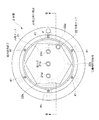
液槽2は、図2、図8及び図9に示すように、外周タンク22及び内周タンク21を主体とした二層構造をなす。内周タンク21は平面視円形状をなし、大気とは遮断された密閉構造としている。この内周タンク21の上部にバブル含有液導入口たる導入口21a、原液供給部から原液が供給される原液供給口21c及び内周タンク21の上層(タンクの深さ方向に対して底面から3/4以上の上方部)にある液体を抜き出すための液抜出口21dが設けられている。内周タンク21の下部すなわち底面にはナノバブル含有液導出部5により装置外部へナノバブル含有液NBを導出する導出口21bが設けられている。外周タンク22は、例えばステンレスといった超音波ssを反射できる材質で構成された平面視六角形状をなす。外周タンク22は、上部に伝搬液を供給するための伝搬液供給口22aを有するとともに下部に伝搬液を排出するための伝搬液排出口22bを有している。そして外周タンク22及び内周タンク21の間に超音波ssを内周タンク21へ伝搬するための伝搬液を貯留する伝搬液貯留領域22cが形成される。
As shown in FIGS. 2, 8 and 9, the
ここで内周タンク21の材質について詳述する。内周タンク21は塩化ビニル樹脂かPVDF等のフッ素系樹脂など樹脂材料又は、石英で構成されることが望ましい。樹脂材料の場合には上部を樹脂溶接や接着などで完全密閉構造とする。石英の場合には、PTFE、バイトン等のシール材を介して密閉構造を採るものとする。その理由は、マイクロバブルの超音波圧壊時に発生する微量ガスを大気と接触させないための処置である。オゾンナノバブル発生時にはオゾンリークによる人体危険を防止するためであり、水素ナノバブルでは、水素と酸素の接触による爆発危険を防止するためである。しかも、この処置によってバブルによる有機合成反応対応でも、気中ガス成分の混入がないため、安定した有機合成反応を得ることが可能となる。
Here, the material of the inner
伝搬液流路8は、外周タンク22内に設けられた温度センサTS1とともに液槽2内の液体の温度を所定の温度範囲内に制御する液温制御部として機能する。この伝搬液流路8は装置外部から外周タンク22の伝搬液供給口22aへと伝搬液を供給する伝搬液供給部81と、外周タンク22の伝搬液排出口22bから装置外部へ伝搬液を排出する伝搬液排出部82とを有している。伝搬液供給部81にはバルブV2が、伝搬液排出部82にはバルブV3が設けられ、これらバルブV2、V3はともに制御部0により制御される。
The
マイクロバブル含有液供給部3は、図2、図6及び図7に示すように、液槽2のバブル含有液導入口に供給流路92を介してマイクロバブルを含有するマイクロバブル含有液MBを供給するためのものである。マイクロバブル含有液供給部3は、液体及び気体を混合させる気液混合器31と、気液混合器31により気体が混合された気泡含有液をマイクロバブル含有液MBとするマイクロバブル生成器32と、マイクロバブル含有液MBが導入口21aへ吐出されるように作動するポンプ39とを有している。ポンプ39については既存のものを使用しているため、その詳細な説明を省略するが、ポンプ39として、例えばエアー駆動型容積式ポンプを適用するが、マグネットポンプや軸流ポンプ等非容積式ポンプを適用しても良く、ポンプの種類を選ばない。
As shown in FIGS. 2, 6, and 7, the microbubble-containing
気液混合器31は、本実施形態では気液混合器31が、ポンプ39よりも液体の流れにおける上流側に設けられているポンプ39の液体取り入れ口近傍に気体取り入れ口を設け、ポンプ39の吸引力を利用して液体と同時に気体も吸引させポンプ39内で気液混合体たる気泡含有液を生じさせるようにしている。斯かる構成を適用している理由は、液体側の流れ方向に添うことで、気液混合を円滑にできるようにすることを目的としているからである。この位置が液体の流れ方向と逆らう場合には、液体の圧力変動を直接受けるため、気体の導入流量が一定せず、気液混合を円滑に行うことができないため、多量の気体が導入されポンプ39が空運転する場合や気体がほとんど入らずバブル発生が定量化しない現象が発生する。これに対して、本実施形態によれば、気体導入圧力が一定圧力で供給することのみで気体導入量が一定となり、安定した気体導入量を維持することが可能となる。
In the present embodiment, the gas-
マイクロバブル生成器32は、気液混合器31を経た気泡含有液を螺旋状に旋回動作させる旋回部材34と、この旋回部材34を経た気泡含有液を突起35aに衝突させながら通過させる突起圧壊部材35と、この突起圧壊部材35を経た気泡含有液を一定時間対流させる畜養部材36と、畜養部材36を経た気泡含有液を発泡させてマイクロバブル含有液MBとする発泡部材37とを有している。また本実施形態では、このマイクロバブル生成器32が、交換可能にモジュール化された構造をなす。詳述すれば、マイクロバブル生成器32は、時間当たりに通過させる通過液量が異なる複数のモジュールから任意の一のモジュールを選択して取り付け得るように構成しているが、通過液量が異なる構成をなすマイクロバブル生成器32については後述する変形例において詳述する。
The
旋回部材34は、内部に螺旋状に形成された旋回面34aに沿って液体を流すものである。この旋回面34aは、少なくとも円軸方向に対して1.5回転以上の円軸回転が得られることが望ましい。気液混合器31によって液中に混入された気泡含有液に、ポンプ39の吐出圧力を利用して旋回流作用を加えることで、流速を加速することができる。円軸方向に対する回転数を上げれば流速は増大するが、その分圧力損失が増大するため、ポンプ39の揚程能力と必要とするバブル濃度から最適回転数は決定される。なお、当該旋回部材34は、特許文献1に示されているような液体のみを旋回させる旋回流ではなく、あくまでも気泡含有液の流速を加速する手段として用いることを特徴としている。このため、この部分でマイクロバブルを発生させるのではない。
The
突起圧壊部材35は、旋回部材34の後段に配置されるものである。突起圧壊部材35は、旋回部材34を通過した気泡含有液を突起35aにより剪断圧壊することによりバブル濃度を向上させる役割を有する。この突起圧壊部材35は円柱構造をなし、円筒方向に対して垂直方向に多段の突起35aを設け、突起35aの先端がそれぞれ対向する方向に配置されたものであって、中心部分に突起35aが存在しない空洞である液流路になるようにしている。また突起35aは少なくとも6段以上の段数になっており、長手方向に36度以上の角度で交互に配置される。さらにこの突起圧壊部材35は旋回部材34と連続し一体的に構成されるものとしている。旋回部材34によって加速された気泡含有液はこの突起35aに当たりながら粉砕され気体がさらに微細化する。本実施形態では、樹脂溶接を用いた構成であるが、突起35aはねじ込み式で構成しても差し支えなく、突起35aの配置は同図の態様の他、90度の角度位相をもって4方向に配置する態様、60度の角度位相をもって6方向に配置する態様でも差し支えはない。また、本実施形態において各突起35a間で36度角度位相を異ならせている理由は、突起35aが並行連続すると先端の突起35aでは気泡含有液を剪断圧壊できるが、後段の突起35aでは先端部分の陰に隠れてその機能を果たすことができないからである。このため、前後の突起35aの角度位相を異ならせることで、後段に位置付けた突起35aも均等に剪断圧壊させることができる。この配列構成により突起35a後方に空間が得られることで、突起35a後方に発生するカルマン流と流れ方向の流体衝突による剪断圧壊効果も得られる(突起35a後方に発生するカルマン流については流体の力学 須藤 浩三他著 コロナ社版 P196に説明されている。)。
The
畜養部材36は、突起圧壊部材35を通過した液体である気泡含有液を一時的に貯留するためのものである。この畜養部材36は、例えばポンプ39の1分間当たりの吐出流量の1/20〜1/5の貯留が可能な容器である。この畜養部材36は、突起圧壊部材35の下流側端部及び発泡部材37の上流側端部が収納されている。
The
発泡部材37は、特に図7に示すように、発泡部材37は、例えば複数のオフセット孔37a1を有するスリット板37aと、液体を加圧する円筒形状をなす再加圧部37bと、テーパ円錐構造をなすテーパ部37cとを有している。スリット板37aは、中心からオフセットさせた位置に、例えば正三角形状をなすように3つのオフセット孔37a1を有している。またこのオフセット孔37a1は、液体の流路に対し所定角度傾斜し、拡散する方向に延出するよう穿たれている。再加圧部37bはオフセット孔37a1を通過した液体である気泡含有液を内部で加圧するためにオフセット孔37a1の開口面積よりも小さい開口面積で液体を流出させる流出口37b2と、この流出口37b2の周囲並びにスリット板37aの裏面側に位置する衝突壁37b1とを有している。テーパ部37cは、流出口37b2から例えば15度よりも小さい角度で円錐状に拡散するテーパ面37c1を有している。斯かる構成により、オフセット孔37a1を通過した液体は加圧されながら傾斜方向に流れて且つ前後の衝突壁37b1に衝突することにより気体がさらに圧壊される。そして流出口37b2を経た液体がテーパ部37cに至ると急速に減圧されることで、気泡含有液がマイクロバブル含有液MBになる。具体的に説明すると、再加圧部37b内の圧力は3MPa前後となっているがテーパ部37cでは1MPaとなり、急激に減圧されることから、発泡部材37を経た液体は均一なマイクロバブルを含有するマイクロバブル含有液MBとなる。
As shown in FIG. 7 in particular, the
とくにこの発泡部材37の急速な減圧により、既知技術では不可能とされたステンレス等を使用しないPVDF、PTFE、PVC等の樹脂でも微細且つ均一なマイクロバブルを得ることが可能となる。なお、既知ベンチュリー構造管では上述のような再加圧機能は得られない。
In particular, the rapid decompression of the foamed
しかして本実施形態では、マイクロバブル含有液供給部3は、上記の気液混合器31、マイクロバブル生成器32及びポンプ39に加え、畜養部材36内の圧力を一定圧力(0.8MPa〜2MPa)程度に高めることで、バブル濃度を向上させる機能を担保するための畜養加圧器33を有している。この畜養加圧器33は、本発明に係るマイクロバブルを微細均一化するための最重要機能の一つであり、剪断圧壊したバブル核内の保有電荷量、ゼータ電位を均一にするため、一定時間滞留をさせること及び余剰気体による加圧圧縮効果を活用して、畜養部材36内の圧力を一定圧力(0.8MPa〜2MPa)程度に高めることで、バブル濃度を向上させる機能を有する。これらの機能によって、ポンプ39が例えば低揚程能力である容積移送型ポンプ(エヤー駆動型ベローズポンプ、同式ダイヤフラムポンプ等)でも微細均一化超高濃度マイクロバブルを発生させることが可能となり、しかも、非容積移送型ポンプ(マグネットポンプや軸流ポンプ等)では、揚程圧が高くなるため、さらなる濃度向上が可能となる。このため、この機能により、ポンプ39の種類を選ばないマイクロバブル含有液供給部3が実現される。なお当該畜養加圧器33により畜養部材36内で加圧された気泡含有液は発泡部材37の再加圧部37bにて再び加圧されている。
Therefore, in the present embodiment, the microbubble-containing
超音波圧壊部4は、外周タンク22に取り付けられた複数の超音波発振子41を有する。本実施形態では、平面視六角形状をなす外周タンク22にそれぞれ放射状に6つの超音波発振子41を取り付けている。すなわちこの超音波発振子41は内周タンク21の中央へ向けて超音波ssを発振し得るように配置されている。そしてこの超音波圧壊部4による超音波ssの発振周波数を20KHz〜1.5MHzとしている。具体的には、28KHz〜1.5MHzの範囲としている。そしてこれら6つの超音波発振子41は、例えば15度程度下方へ傾斜した方向に超音波ssを発振するように配されている。
The ultrasonic crushing
<作用説明>
しかして本実施形態に係るナノバブル製造装置では、超音波圧壊部4の作動により内周タンク21の平面視中央において、バブル含有液導入口を通して液槽2内に供給されたマイクロバブル含有液MBが下方へ向けて流れる箇所に超音波ssによるマイクロバブルの圧壊が集中して起こりナノバブルが生成される超音波圧壊場Xが形成される。具体的に説明すると、超音波発振子41から伝搬された超音波エネルギーは外周タンク22のステンレス板等の壁面で反射し、その反射エネルギーも相まって内周タンク21内で超音波圧壊場Xを形成する構成となっている。換言すれば、超音波圧壊部4によって液槽2内の超音波ssは、角柱又は円柱状をなす中心部分すなわち超音波圧壊場X内に超音波ssを集中させてマイクロバブルの逃げ場をなくしながら圧壊する。これにより、ナノバブルを形成することを特徴とする。このため、超音波ssのエネルギーと周波数を適宜選択することで、中心粒径100nm前後以下且つバブル濃度3億個/ml以上の望ましいナノバブル含有液NBを得ることが可能となる。
<Description of action>
Therefore, in the nanobubble manufacturing apparatus according to the present embodiment, the microbubble-containing liquid MB supplied into the
他方、従来も超音波で新たなナノバブルを得る技術としてはナノバブルの発生と機能に関する研究等があるが、濃度が低くナノバブルの寿命が短命で高濃度できないものであった(筑波大学大学院博士課程 システム情報工学研究科修士論文ナノバブルの発生と機能に関する研究 後藤 瑞希 2004年1月)。また、マイクロバブルから圧壊法でナノバブルを得る方法は特開2005−246293号公報、特開2011−218308号公報記載の技術が考案されている。しかしながら、前者では、単に超音波を当てることやオリフィス構造多孔板を用いて物理的刺激を与えること。電圧印加による物理的刺激を加えることのみであり、500nm以下のナノバブルはそれ以上微細化できないことをYoung−Laplaceの式を用いて説明をしている。さらに、特開2011−218308号公報等では、収容室の底面から上部に向かって超音波を印加する手法が考案されているが、この手法では超音波を印加する反対側方向にマイクロバブルやナノバブルがその振動エネルギーで移動するため、高濃度ナノバブルを生成することはできなかった。 On the other hand, there have been researches on the generation and function of nanobubbles as a technology for obtaining new nanobubbles with ultrasound, but the concentration was low and the lifetime of nanobubbles was short-lived and could not be high (University of Tsukuba Graduate School Doctoral Program System). Master's thesis, Graduate School of Information Engineering Research on generation and function of nanobubbles Mizuki Goto (January 2004). Moreover, the technique of Unexamined-Japanese-Patent No. 2005-246293 and Unexamined-Japanese-Patent No. 2011-218308 is devised as the method of obtaining a nanobubble from a microbubble by the crushing method. However, in the former, simply applying ultrasonic waves or applying a physical stimulus using an orifice structure perforated plate. Only the physical stimulation by applying voltage is applied, and nanobubbles of 500 nm or less cannot be further refined using the Young-Laplace equation. Furthermore, in Japanese Patent Laid-Open No. 2011-218308, etc., a method of applying ultrasonic waves from the bottom to the top of the storage chamber has been devised. In this method, microbubbles and nanobubbles are applied in the opposite direction to which ultrasonic waves are applied. However, high-density nanobubbles could not be generated because it moves with its vibrational energy.
<動作説明>
以下、本実施形態に係るナノバブル製造装置の動作フローについて説明する。
<Description of operation>
Hereinafter, the operation flow of the nanobubble manufacturing apparatus according to the present embodiment will be described.
まず、筐体1に露出している操作パネル00によりユーザが動作開始指令を入力すると、バルブV2が開かれ、外周タンク22に伝搬液が供給される。そして図示しない水位センサが外周タンク22における伝搬液貯留領域22c内で伝搬液が一定量に至ることを検知するまで外周タンク22に伝搬液が供給され続ける。続いて伝搬液が一定量に至ること検知すると、制御部0よりバルブV2閉の指令を出し、バルブV2が閉となって伝搬液の供給を停止する。そして内周タンク21内の図示しない水位センサにより内周タンク21内の液体が十分量に至っていないことを制御部0が確認すると、バルブV1を開にして、原液導入部7からの原液供給を開始する。内周タンク21内の液量が上限であると水位センサがセンシングするまで、この動作は継続する。つまり水位センサが内周タンク21に十分原液が貯留された旨を検知すると制御部0がバルブV1に対し閉指令を出し、原液供給は停止となる。
First, when the user inputs an operation start command through the
しかる後、制御部0よりスイッチV5へ開指令を出され、ポンプ39が動作を開始する。なお本実施形態ではポンプ39として、例えばエアー駆動式ポンプを適用するが、軸流式、マグネットポンプを適用する場合には、リレー等で電源をONにして電気ポンプへの電源供給が開始されるようにすれば良い。この時、バルブV6は、閉のまま一定時間維持される。このときバブル化対象気体たるオゾンは気液混合器31へは供給されずアイドリング運転が実行される。アイドリング時間の設定は、制御部0に予め適宜の時間に設定されている。そして設定されたアイドリング時間終了後、制御部0よりバルブV6へ開指令を出し、これによりオゾンが気液混合器31に供給される。供給されたオゾンは気液混合器31を経てポンプ39へ供給され、マイクロバブル生成器32を経て、マイクロバブル含有液MBを生成し、液槽2内において超音波圧壊部4によりナノバブル含有液NBに変換される。
Thereafter, an opening command is issued from the
液槽2内では、内周タンク21の上部はマイクロバブル含有液MB、中層部はマイクロバブル・ナノバブル混在液MN、下層部分はナノバブル含有液NBの支配域となる。この動作の繰り返しにより、ナノバブルを下層域より高濃度化していくことが可能となる。すなわち運転中、液循環機構9により液体が内周タンク21とマイクロバブル含有液供給部3との間を循環していくことにより、内周タンク21内下層部分に生成されるナノバブル含有液NBのナノバブル濃度は逓増していく。
In the
そして内周タンク21下層部分に生成されたナノバブル含有液NBはユーザが操作パネル00を操作することによりバルブV4を開とすれば、ナノバブル含有液導出部5から所要量のナノバブル含有液NBを得ることができる。
When the user opens the valve V4 by operating the
ここで、継続運転中、伝搬液貯留領域22cでは、伝搬液に対し連続的に超音波ssが印加され続けると、徐々に伝搬液温が上昇する。この液温を温度センサTS1がセンシングするようにしている。つまり、温度センサTS1により伝搬液温がその設定温度に達した場合、制御部0がバルブV3を開にして、一部の伝搬液を排出するとともにバルブV2を開にして、伝搬液の一部を入れ替え、伝搬液温の温度上昇を抑制する。ここで供給される伝搬液は使用に適した温度範囲内にあることはいうまでもない。
Here, during the continuous operation, in the propagation
以上のようなものとすることにより、本実施形態に係るナノバブル製造装置は、微細で径が均一であり且つ高濃度のナノバブル含有液NBを得ることができる。具体的にはマイクロバブル含有液供給部3により200nm〜2μm前後のマイクロバブル含有液MBを生成するとともに、このマイクロバブル含有液MBに対し図9に示した超音波圧壊場Xを形成しさらに圧壊することで、中心粒径100nm前後以下且つバブル濃度3億個/ml以上の達成ができるホモジニアスナノバブル製造装置を実現するものである。
By setting it as the above, the nanobubble manufacturing apparatus which concerns on this embodiment can obtain the nanobubble containing liquid NB with a fine and uniform diameter and high concentration. Specifically, the microbubble-containing
また、より好適な超音波圧壊場Xを形成するための具体的な構成として本実施形態では、導入口21aが液槽2の平面視中央に配し、超音波圧壊部4が液槽2の平面視中央に超音波圧壊場Xを形成する構成を適用している。
Further, as a specific configuration for forming a more preferable ultrasonic crushing field X, in the present embodiment, the
そしてナノバブルをより好適に生成し得るために本実施形態では、超音波の発振周波数を20KHz〜1.5MHzとしている。 In order to generate nanobubbles more suitably, in this embodiment, the ultrasonic oscillation frequency is set to 20 KHz to 1.5 MHz.
また、超音波圧壊部4からナノバブル含有液NBをより好適に得るための構成として本実施形態では、超音波圧壊部4が超音波を発振し得る超音波発振子41を有し、液槽2が、超音波発振子41を固定した外周タンク22と、この外周タンク22よりも内側に形成されバブル含有液及び導出口21bを配する内周タンク21とを有し、これら外周タンク22及び内周タンク21の間に超音波を内周タンク21へ伝搬するための伝搬液を貯留する伝搬液貯留領域22cを形成している態様を適用している。
In the present embodiment, the ultrasonic crushing
さらに効率良く超音波圧壊場Xを形成するために本実施形態では超音波圧壊部4が超音波発振子41を複数有しているものとしている。
In order to form the ultrasonic crushing field X more efficiently, the ultrasonic crushing
また、液槽2及び超音波圧壊部4の具体的な構成として本実施形態では、内周タンク21が平面視円形状をなすものであり、複数の超音波発振子41が内周タンク21の中央へ向けて超音波を発振し得るように平面視放射状に配されている構成を適用している。
In the present embodiment, the specific configuration of the
そして均一な径を有するナノバブル含有液NBをより効率良く得るために本実施形態では、複数の超音波発振子41を、下方へ傾斜した方向に超音波を発振するように配している。
In order to obtain the nanobubble-containing liquid NB having a uniform diameter more efficiently, in this embodiment, the plurality of
そして、ナノバブル含有液NBを構成する気体並びに液体の種類に依存することなく効率良くナノバブル含有液NBを得るために本実施形態では、内周タンク21を、大気とは遮断された密閉構造としている。
In order to obtain the nanobubble-containing liquid NB efficiently without depending on the type of gas and liquid constituting the nanobubble-containing liquid NB, in this embodiment, the inner
そして、効率よくナノバブル含有液NBを得るべく、ナノバブルを生成し易いマイクロバブル含有液MBを液槽2に効率よく供給するために本実施形態では、マイクロバブル含有液供給部3が、液体及び気体を混合させる気液混合器31と、気液混合器31により気体が混合された液体をマイクロバブル含有液MBとするマイクロバブル生成器32と、マイクロバブル含有液MBが導入口21aへ吐出されるように作動するポンプ39とを有している態様を採用している。
In order to efficiently supply the nanobubble-containing liquid NB to the
そしてより性能が高いマイクロバブル生成器32を実現するための具体的な構成として本実施形態では、マイクロバブル生成器32が、気液混合器31を経た気泡含有液を螺旋状に旋回動作させる旋回部材34と、この旋回部材34を経た気泡含有液を突起35aに衝突させながら通過させる突起圧壊部材35と、この突起圧壊部材35を経た気泡含有液を一定時間対流させる畜養部材36と、畜養部材36を経た気泡含有液を発泡させてマイクロバブル含有液MBとする発泡部材37とを有している構成を適用している。
In the present embodiment, as a specific configuration for realizing the
特に本実施形態では、効率よくマイクロバブル含有液MBを得るために、マイクロバブル含有液供給部3が、畜養部材36内の液体を加圧する畜養加圧器33を設けている。
In particular, in the present embodiment, in order to obtain the microbubble-containing liquid MB efficiently, the microbubble-containing
また、液槽2に効率よくマイクロバブル含有液MBを供給するために本実施形態では、マイクロバブル含有液供給部3が、液槽2の上側からポンプ39によりマイクロバブル生成器32へ液体を抽出する液抽出路91を設けて液循環機構9を構成し、内周タンク21の下部に高濃度ナノバブル含有液NBを生成し得るものとしている。内周タンク21の実液残量の深さ方向で、底面より3/4以上であれば、マイクロバブル支配域となるため、ナノバブルをポンプ39側へ排出することもなく、ナノバブルを高濃度化できる。つまり本実施形態では、マイクロバブル支配域である内周タンク21上部から液体を抜き出してポンプ39側へ環流させることで既に内周タンク21内に存在するナノバブルをポンプ39側へ排出させることなく、マイクロバブルのみをポンプ39側へ排出させるため、ナノバブルの有する分散効果によって更なるナノバブルの高濃度化が実現されている。
In this embodiment, in order to efficiently supply the microbubble-containing liquid MB to the
これら本実施形態に係る各構成による相乗効果により、結果として粒径100nm前後以下であり、且つ3億個/ml以上に高濃度化されたナノバブル含有液NBをユーザは安定して得ることができる。 As a result, the user can stably obtain the nanobubble-containing liquid NB having a particle size of about 100 nm or less and a high concentration of 300 million / ml or more due to the synergistic effect of each configuration according to the present embodiment. .
そして、継続的な使用においてもナノバブル含有液NBの製造効率を高く維持しておくために本実施形態では、伝搬液を適宜入れ替えることにより液槽2内の液体の温度を所定の温度範囲内に制御するようにしている。
In order to keep the production efficiency of the nanobubble-containing liquid NB high even in continuous use, in this embodiment, the temperature of the liquid in the
なお本発明とは異なり、タンクを用いてナノバブルの高濃度化を図る場合、特開2005−246293等では、循環ポンプとオリフィス等の多孔板を用いて、循環させ物理的刺激を与える手法や超音波圧壊を使用しながらナノバブルを微細気泡発生装置に環流させ高濃度化を図る手法が考案されている。しかしながら、これらの手法では、マイクロバブルを一定限度ナノバブル化はできるものの、粒径100nm以下のナノバブルを高濃度に生成することはできないことが明細書中に記述されており、特に、ナノバブルを微細気泡発生装置側に環流させるとバブル粒径の違いによる保有電荷量とゼータ電位の違いによりバブル凝集現象が生じること及びタンク内のナノバブルを排出するため、更なる高濃度化を得ることができない。特許第3762206号公報、同4094633号公報についても上記同様である。 Unlike the present invention, when increasing the concentration of nanobubbles using a tank, JP 2005-246293, etc., uses a circulating pump and a perforated plate such as an orifice to circulate and provide physical stimulation. A technique has been devised in which nanobubbles are circulated through a microbubble generator while using sonic crushing to increase the concentration. However, in these methods, it is described in the specification that although microbubbles can be made into nanobubbles to a certain limit, nanobubbles having a particle size of 100 nm or less cannot be generated at a high concentration. When refluxed to the generator side, bubble aggregation phenomenon occurs due to the difference in the amount of charge retained and the zeta potential due to the difference in bubble particle size, and nanobubbles in the tank are discharged, so that further increase in concentration cannot be obtained. The same applies to Japanese Patent Nos. 3762206 and 4094633.
<変形例1>
以下、本実施形態の各変形例について説明する。以下の各変形例について、上記実施形態の構成要素に相当するものに対しては同じ符号を付すとともに、その詳細な説明を省略する。
<
Hereinafter, each modification of the present embodiment will be described. In each of the following modifications, the same reference numerals are assigned to the components corresponding to the constituent elements of the above-described embodiment, and detailed description thereof is omitted.
当該変形例1は上記実施形態の図2におけるA部の構成を、図10の如く変更したものである。つまり、本変形例は、ポンプ39の吐出部後段側に気液混合器31を配置して気泡含有液を形成し、この気泡含有液をマイクロバブル生成器32の旋回部材34へ導入することでマイクロバブル含有液MBを生成するものである。当該図10に示すように、気液混合器31が、ポンプ39とマイクロバブル生成器32との間に設けられているものであっても上記実施形態同様の効果を得ることができる。
The
なお図示しないが、旋回部材34の構成を変更し、旋回部材34の中段部分から気体を導入する態様としても良い。つまり旋回部材34が気液混合器31の構成を兼ねる態様としても、同様の効果を奏し得る。
Although not shown, the configuration of the
<変形例2>
上記実施形態においてはマイクロバブル生成器32を、交換可能にモジュール化されたものである態様、具体的にはマイクロバブル生成器32が、時間当たりに通過させる液量が異なる複数のモジュールから任意の一のモジュールを選択して取り付け得る構成を開示したが、上記図6に示したマイクロバブル生成器32に代えて、図11に示すようなマイクロバブル生成器32を適用することができる。
<
In the above-described embodiment, the
すなわち同図に示すマイクロバブル生成器32は、上記実施形態のものよりも単位時間当たりのマイクロバブル含有液MBの生成量を増大させたい場合に使用する。このように、上記実施形態のものよりも容量が大きな共通の畜養部材36に対し、旋回部材34、突起圧壊部材35及び発泡部材37を複数組接続するとともに、上流側及び下流側で流路を合流させる形状とすることで、図6に示したものと選択的に交換し得るようにしたものである。また図11では複数の旋回部材34、突起圧壊部材35及び発泡部材37を直線状に並列させて図示したが勿論、筐体1内のスペースの有効利用に資するべく束状に配置しても良い。
That is, the
<変形例3>
上記実施形態では平面視六角形状をなす外周タンク22を有する液槽2及び当該液槽2に対し6つの超音波発振子41を適用した超音波圧壊部4を適用した態様を開示したが、図12に示す態様のものであっても良い。
<
In the above embodiment, the
図12に示すように、液槽2は上記実施形態同様2重構造であるものの外周タンク22、内周タンク21ともに平面視矩形状をなしている。そして外周タンク22の対抗軸2軸に配置された対をなす超音波発振子41を有する超音波圧壊部4を有する。斯かる構成のものは超音波ssによる振動エネルギーを、伝搬液を介して内周タンク21内へ伝搬し、内周タンク21内で超音波圧壊場Xを形成する構造である点は上記実施形態同様である。
As shown in FIG. 12, the
同図では超音波発振子41から伝搬された超音波ssは外周タンク22部の壁面で反射し、その反射超音波rwと超音波ssとの波形の重なりにより内周タンク21内で超音波圧壊場Xを形成する構成となっている。すなわちこの構成は少なくともX軸、Y軸の2軸に超音波発振子41を配置したことを特徴とするものである。斯かる構成であっても上記実施形態同様、超音波の反射や照射により、角柱又は円柱形状をなす超音波圧壊場Xを形成できる。
In the figure, the ultrasonic wave ss propagated from the
なお上記構成に対し、既知技術である特開2005−246293号公報、特開2011−218308号公報による超音波印加によるマイクロバブル状態はいずれも超音波エネルギーの印加によって印加方向にマイクロバブルが移動する結果、気液界面に浮上して崩壊するため、ナノバブル濃度が飛躍的に向上することはない。 In addition to the above configuration, in the microbubble state by the application of ultrasonic waves according to the known techniques of Japanese Patent Laid-Open Nos. 2005-246293 and 2011-218308, the microbubbles move in the application direction by the application of ultrasonic energy. As a result, since it floats and collapses at the gas-liquid interface, the concentration of nanobubbles does not increase dramatically.
<変形例4>
さらに、上記実施形態では液循環機構9を設ける事により、液槽2・マイクロバブル含有液供給部3間で液体を循環させる、所謂循環タイプのナノバブル製造装置を開示したが、本変形例の通り、原液供給部7からナノバブル含有液導出部5までを単一の通路上に順に、マイクロバブル含有液供給部3、供給流路92、液槽2、超音波圧壊部4を設けた、所謂ワンパス式のナノバブル製造装置を構成しても良い。
<
Furthermore, in the above-described embodiment, a so-called circulation type nanobubble manufacturing apparatus that circulates liquid between the
同変形例に示すナノバブル製造装置は図13に示す通り、原液導入部7が液槽には接続せず、マイクロバブル含有液供給部3の気液混合器31へ、バルブV1を設けながら直接接続している。そして図14に示すように、液槽2には上記実施形態とは異なり、内周タンク21側に原液導入口21c及び液抜出口21dを設けず、導入口21a及び導出口21bのみを設けた構成としている。
As shown in FIG. 13, the nanobubble production apparatus shown in this modification is not directly connected to the liquid tank, but the raw
このようなものであっても、上記実施形態同様の効果、すなわち所要の濃度のナノバブルを含むナノバブル含有液NBを安定して得ることができる。 Even if it is such, the effect similar to the said embodiment, ie, the nanobubble containing liquid NB containing the nanobubble of a required density | concentration can be obtained stably.
以上、本発明の実施形態及び各変形例について説明したが、各部の具体的な構成は、上述した実施形態のみに限定されるものではなく、本発明の趣旨を逸脱しない範囲で種々変形が可能である。 As mentioned above, although embodiment and each modification of this invention were demonstrated, the specific structure of each part is not limited only to embodiment mentioned above, A various deformation | transformation is possible in the range which does not deviate from the meaning of this invention. It is.
例えば、上記実施形態では内周タンクから直接的にナノバブル含有液を取り出す態様を開示したが、勿論、内周タンクよりも下流側に、ナノバブル含有液のみを貯留しておくための別異のタンクを設けたしたものであってもよい。また上記実施形態では液槽は、外周タンク及び内周タンクを具備する二重構造としたが勿論、斯かる構成に限られず、外周タンクのみの一重構造のものとして外周タンク内で直接超音波圧壊場を生成する態様、換言すれば伝搬液を使用しない態様としても良い。またポンプや超音波発振子の具体的な態様は上記実施形態のものに限定されることはなく、既存のものを含め、種々の態様のものを適用することができる。 For example, in the above-described embodiment, the aspect of taking out the nanobubble-containing liquid directly from the inner peripheral tank has been disclosed, but, of course, a different tank for storing only the nanobubble-containing liquid downstream from the inner peripheral tank. It may be provided. In the above embodiment, the liquid tank has a double structure including an outer peripheral tank and an inner peripheral tank. Of course, the liquid tank is not limited to such a configuration, and the ultrasonic tank is directly crushed in the outer peripheral tank as a single structure having only the outer peripheral tank. It is good also as an aspect which does not use the aspect which produces | generates a field, in other words, propagation liquid. Further, specific modes of the pump and the ultrasonic oscillator are not limited to those of the above-described embodiment, and various modes including the existing ones can be applied.
その他、各部の具体的構成についても上記実施形態に限られるものではなく、本発明の趣旨を逸脱しない範囲で種々変形が可能である。 In addition, the specific configuration of each part is not limited to the above embodiment, and various modifications can be made without departing from the spirit of the present invention.
本発明はナノバブル含有液を製造するナノバブル製造装置として利用することができる。 The present invention can be used as a nanobubble production apparatus for producing a nanobubble-containing liquid.
2…液槽
21…内周タンク
21a…バブル含有液導入口(導入口)
21b…バブル含有液導出口(導出口)
22…外周タンク
22c…伝搬液貯留領域
3…マイクロバブル含有液供給部
31…気液混合器
32…マイクロバブル生成器
33…畜養加圧器
34旋回部材
35…突起圧壊部材
36…畜養部材
37…発泡部材
39…ポンプ
4…超音波圧壊部
41…超音波発振子
5…ナノバブル含有液導出部
MB…マイクロバブル含有液
NB…ナノバブル含有液
X…超音波圧壊場
2 ...
21b ... Bubble-containing liquid outlet (outlet)
DESCRIPTION OF
Claims (16)
この液槽の前記バブル含有液導入口にマイクロバブルを含有するマイクロバブル含有液を供給するマイクロバブル含有液供給部と、
前記バブル含有液導入口を通して前記液槽内に供給された前記マイクロバブル含有液が下方へ向けて流れる箇所に超音波によるマイクロバブルの圧壊が集中して起こりナノバブルが生成される超音波圧壊場を形成するために前記液槽内へ超音波を照射する超音波圧壊部と、
この超音波圧壊部により生成されたナノバブルを含有するナノバブル含有液を、前記バブル含有液導出口を通して前記液槽外に取り出すナノバブル含有液導出部とを具備し、
前記超音波圧壊部が超音波を発振し得る超音波発振子を有し、
前記液槽が、前記超音波発振子を固定した外周タンクと、この外周タンクよりも内側に形成され前記バブル含有液導入口及びバブル含有液導出口を配する内周タンクとを有し、これら外周タンク及び内周タンクの間に超音波を前記内周タンクへ伝搬するための伝搬液を貯留する伝搬液貯留領域を形成しているナノバブル製造装置。 A liquid tank in which a bubble-containing liquid inlet is arranged at the top and a bubble-containing liquid outlet is arranged at the bottom;
A microbubble-containing liquid supply unit for supplying a microbubble-containing liquid containing microbubbles to the bubble-containing liquid inlet of the liquid tank;
An ultrasonic crushing field in which crushing of microbubbles due to ultrasonic waves concentrates on a location where the microbubble-containing liquid supplied into the liquid tank flows downward through the bubble-containing liquid introduction port and nanobubbles are generated. An ultrasonic crushing portion for irradiating ultrasonic waves into the liquid tank to form,
A nanobubble-containing liquid lead-out part that takes out the nanobubble-containing liquid containing nanobubbles generated by the ultrasonic crushing part through the bubble-containing liquid lead-out port and out of the liquid tank, and
The ultrasonic crushing portion has an ultrasonic oscillator that can oscillate ultrasonic waves,
The liquid tank has an outer peripheral tank to which the ultrasonic oscillator is fixed, and an inner peripheral tank that is formed inside the outer peripheral tank and has the bubble-containing liquid inlet and the bubble-containing liquid outlet. The nanobubble manufacturing apparatus which forms the propagation liquid storage area | region which stores the propagation liquid for propagating an ultrasonic wave to the said inner periphery tank between an outer peripheral tank and an inner peripheral tank.
前記超音波圧壊部が前記液槽の平面視中央に前記超音波圧壊場を形成するものである請求項1に記載のナノバブル製造装置。 The bubble-containing liquid inlet is disposed in the center of the liquid tank in plan view,
The nanobubble manufacturing apparatus according to claim 1, wherein the ultrasonic crushing part forms the ultrasonic crushing field in the center of the liquid tank in plan view.
Priority Applications (5)
| Application Number | Priority Date | Filing Date | Title |
|---|---|---|---|
| JP2014064892A JP6210917B2 (en) | 2014-03-26 | 2014-03-26 | Nano bubble production equipment |
| KR1020167025356A KR101886944B1 (en) | 2014-03-26 | 2015-03-25 | Nanobubble producing device |
| US15/127,372 US10596528B2 (en) | 2014-03-26 | 2015-03-25 | Nanobubble-producing apparatus |
| PCT/JP2015/059107 WO2015147048A1 (en) | 2014-03-26 | 2015-03-25 | Nanobubble-producing device |
| EP15769582.6A EP3124109A4 (en) | 2014-03-26 | 2015-03-25 | Nanobubble-producing device |
Applications Claiming Priority (1)
| Application Number | Priority Date | Filing Date | Title |
|---|---|---|---|
| JP2014064892A JP6210917B2 (en) | 2014-03-26 | 2014-03-26 | Nano bubble production equipment |
Publications (3)
| Publication Number | Publication Date |
|---|---|
| JP2015186781A JP2015186781A (en) | 2015-10-29 |
| JP2015186781A5 JP2015186781A5 (en) | 2017-06-08 |
| JP6210917B2 true JP6210917B2 (en) | 2017-10-11 |
Family
ID=54195559
Family Applications (1)
| Application Number | Title | Priority Date | Filing Date |
|---|---|---|---|
| JP2014064892A Active JP6210917B2 (en) | 2014-03-26 | 2014-03-26 | Nano bubble production equipment |
Country Status (5)
| Country | Link |
|---|---|
| US (1) | US10596528B2 (en) |
| EP (1) | EP3124109A4 (en) |
| JP (1) | JP6210917B2 (en) |
| KR (1) | KR101886944B1 (en) |
| WO (1) | WO2015147048A1 (en) |
Cited By (1)
| Publication number | Priority date | Publication date | Assignee | Title |
|---|---|---|---|---|
| US10596528B2 (en) * | 2014-03-26 | 2020-03-24 | Tosslec Co., Ltd. | Nanobubble-producing apparatus |
Families Citing this family (28)
| Publication number | Priority date | Publication date | Assignee | Title |
|---|---|---|---|---|
| JP6132412B2 (en) | 2015-09-24 | 2017-05-24 | 株式会社Subaru | Outside environment recognition device |
| CN107486093A (en) * | 2016-06-13 | 2017-12-19 | 临萃(上海)实业有限公司 | The micro-nano bubble generator of ultrasonic cutting |
| JP6123013B1 (en) * | 2016-10-19 | 2017-04-26 | トスレック株式会社 | Bubble-containing liquid manufacturing apparatus and bubble-containing liquid manufacturing method |
| WO2018073987A1 (en) * | 2016-10-19 | 2018-04-26 | トスレック株式会社 | Method for manufacturing and system for manufacturing beverage or other liquid containing bubbles |
| KR101916455B1 (en) * | 2016-11-11 | 2018-11-07 | 대구대학교 산학협력단 | Deodorizing apparatus for spraying oxidant complex mist and Deodorizing method thereof |
| JP2018122294A (en) * | 2017-02-03 | 2018-08-09 | トスレック株式会社 | Bubble generation nozzle and bubble-containing liquid production system comprising the same |
| JP6884955B2 (en) * | 2017-02-21 | 2021-06-09 | トスレック株式会社 | Hydrogen water production system and hydrogen water production method |
| JP6630922B2 (en) * | 2017-02-22 | 2020-01-15 | トスレック株式会社 | Hydrogen water, its production system and production method |
| GR20170100128A (en) * | 2017-03-30 | 2018-10-31 | Ευαγγελος Παναγη Φαβας | METHOD AND PRODUCTION OF NANO-BALANCE |
| JP2018065124A (en) * | 2017-04-03 | 2018-04-26 | トスレック株式会社 | Bubble-containing liquid manufacturing apparatus and bubble-containing liquid manufacturing method |
| JP7185390B2 (en) * | 2017-04-13 | 2022-12-07 | 東芝ライフスタイル株式会社 | Cleaning methods, washing machines, dishwashers, and toilet bowls |
| JP7309826B2 (en) * | 2017-04-13 | 2023-07-18 | 東芝ライフスタイル株式会社 | Cleaning methods, washing machines, dishwashers, and toilet bowls |
| JP7106089B2 (en) * | 2017-09-22 | 2022-07-26 | トスレック株式会社 | Microbubble sterilization system and method for sterilizing seafood, beverages and foods |
| JP7018610B2 (en) * | 2018-01-15 | 2022-02-14 | 株式会社三進製作所 | Micro bubble generator and micro bubble generator |
| CN108745012B (en) * | 2018-06-14 | 2021-04-20 | 四川大学 | But miniature venturi type bubble generating device of modularization combination |
| US11904366B2 (en) * | 2019-03-08 | 2024-02-20 | En Solución, Inc. | Systems and methods of controlling a concentration of microbubbles and nanobubbles of a solution for treatment of a product |
| EP3970574A4 (en) * | 2019-05-17 | 2023-01-25 | Severin Asia Limited | Device and method for extracting components in solid by using nanobubbles |
| JP7240260B2 (en) * | 2019-06-04 | 2023-03-15 | 株式会社荏原製作所 | GAS SOLUTION SUPPLY DEVICE AND GAS SOLUTION SUPPLY METHOD |
| WO2021085629A1 (en) * | 2019-10-31 | 2021-05-06 | キヤノン株式会社 | Method for producing ultra-fine bubble-containing liquid, ultra-fine bubble-containing liquid, method for utilizing ultra-fine bubbles, and device for utilizing ultra-fine bubbles |
| TWI727524B (en) * | 2019-11-27 | 2021-05-11 | 國家中山科學研究院 | Multi-dimensional vibration grinding cavity |
| KR102315756B1 (en) * | 2019-12-23 | 2021-10-21 | 임은정 | Apparatus for generating Nano-bubble water |
| JP2021126601A (en) * | 2020-02-12 | 2021-09-02 | キヤノン株式会社 | Ufb-containing liquid production device and ufb-containing liquid production method |
| CA3178944A1 (en) * | 2020-05-21 | 2021-11-25 | Arbela Laboratories, Inc. | Aerobic fermentation systems and methods of using the same |
| US11344852B1 (en) | 2021-06-15 | 2022-05-31 | Enrichment Systems Llc | Hydroponic system and method for enriching a liquid with gas-bubbles |
| CN113926352A (en) * | 2021-10-29 | 2022-01-14 | 四川大学华西医院 | Microbubble preparation instrument and microbubble preparation method |
| KR102627552B1 (en) * | 2022-01-24 | 2024-01-19 | 금오공과대학교 산학협력단 | A gas saturation control system and an ultrasonic cavitation detection system including the same |
| IT202200005246A1 (en) * | 2022-03-17 | 2023-09-17 | Yvonne Massari | MOBILE DEVICE FOR THE PRODUCTION OF OZONE WATER FOR ENVIRONMENTAL SANITIZATION |
| KR102596925B1 (en) | 2022-08-18 | 2023-11-01 | 주식회사 알티자동화 | Nano bubble water generator for semiconductor cleaning |
Family Cites Families (21)
| Publication number | Priority date | Publication date | Assignee | Title |
|---|---|---|---|---|
| JP2001225060A (en) * | 1999-12-08 | 2001-08-21 | Mitsubishi Heavy Ind Ltd | Water treatment method and its device |
| JP3762206B2 (en) * | 2000-09-13 | 2006-04-05 | 株式会社アスプ | Ultra-fine bubble generator |
| DE10243837A1 (en) * | 2002-09-13 | 2004-03-25 | Dr. Hielscher Gmbh | Process for continuously processing flowable compositions in a flow cell comprises indirectly sonicating the composition in the flow cell via a liquid placed under elevated pressure |
| JP4059506B2 (en) | 2004-03-05 | 2008-03-12 | 独立行政法人産業技術総合研究所 | Ozone water and method for producing the same |
| JP4725707B2 (en) | 2004-09-27 | 2011-07-13 | 株式会社 ナノプラネット研究所 | Swivel type fine bubble generator and bubble generation method |
| JP2006136777A (en) * | 2004-11-11 | 2006-06-01 | Maruwa Biochemical Co Ltd | Mixing apparatus for fine bubble |
| JP2006272232A (en) | 2005-03-30 | 2006-10-12 | Hitachi Ltd | Method for forming superfine bubble, its device and sterilizing or disinfecting facility using it |
| JP2006289183A (en) * | 2005-04-06 | 2006-10-26 | Nano Bubble Kk | Nano-bubble forming method and apparatus |
| JP4430609B2 (en) * | 2005-11-14 | 2010-03-10 | ヤーマン株式会社 | Nano bubble generator |
| JP4094633B2 (en) | 2005-11-30 | 2008-06-04 | ナノバブル株式会社 | Ultra-fine bubble generator |
| JP2008264771A (en) * | 2007-03-22 | 2008-11-06 | Shunsuke Miyao | Manufacturing apparatus of micro-bubble water and nano-bubble water |
| US9266073B2 (en) * | 2007-03-28 | 2016-02-23 | William B. Kerfoot | Treatment for recycling fracture water—gas and oil recovery in shale deposits |
| JP4866295B2 (en) * | 2007-06-01 | 2012-02-01 | 株式会社 シンワ | Fine bubble sorting and collection device |
| JP2009178683A (en) * | 2008-01-31 | 2009-08-13 | Powrex Corp | Suspension production apparatus and suspension production method |
| WO2010134551A1 (en) * | 2009-05-19 | 2010-11-25 | パナソニック電工株式会社 | Gas-liquid mixture |
| JP5390285B2 (en) | 2009-07-13 | 2014-01-15 | 株式会社大日工業 | Nano bubble generator |
| JP2011218308A (en) * | 2010-04-12 | 2011-11-04 | Asupu:Kk | Gas-dissolved liquid generating apparatus and method for generation |
| JP2015037765A (en) * | 2011-12-16 | 2015-02-26 | パナソニック株式会社 | Nanobubble-containing liquid |
| JP2014050817A (en) * | 2012-09-10 | 2014-03-20 | Panasonic Corp | Control method of particle size of fine bubble |
| JP6270402B2 (en) * | 2013-10-17 | 2018-01-31 | 株式会社アスプ | Gas-containing liquid generator and gas-containing liquid injection mechanism |
| JP6210917B2 (en) * | 2014-03-26 | 2017-10-11 | トスレック株式会社 | Nano bubble production equipment |
-
2014
- 2014-03-26 JP JP2014064892A patent/JP6210917B2/en active Active
-
2015
- 2015-03-25 US US15/127,372 patent/US10596528B2/en not_active Expired - Fee Related
- 2015-03-25 KR KR1020167025356A patent/KR101886944B1/en active IP Right Grant
- 2015-03-25 WO PCT/JP2015/059107 patent/WO2015147048A1/en active Application Filing
- 2015-03-25 EP EP15769582.6A patent/EP3124109A4/en not_active Withdrawn
Cited By (1)
| Publication number | Priority date | Publication date | Assignee | Title |
|---|---|---|---|---|
| US10596528B2 (en) * | 2014-03-26 | 2020-03-24 | Tosslec Co., Ltd. | Nanobubble-producing apparatus |
Also Published As
| Publication number | Publication date |
|---|---|
| EP3124109A1 (en) | 2017-02-01 |
| KR20160120766A (en) | 2016-10-18 |
| JP2015186781A (en) | 2015-10-29 |
| US20180178173A1 (en) | 2018-06-28 |
| KR101886944B1 (en) | 2018-08-08 |
| US10596528B2 (en) | 2020-03-24 |
| WO2015147048A1 (en) | 2015-10-01 |
| EP3124109A4 (en) | 2017-11-22 |
Similar Documents
| Publication | Publication Date | Title |
|---|---|---|
| JP6210917B2 (en) | Nano bubble production equipment | |
| JP2015186781A5 (en) | ||
| JP6123013B1 (en) | Bubble-containing liquid manufacturing apparatus and bubble-containing liquid manufacturing method | |
| JP2006289183A (en) | Nano-bubble forming method and apparatus | |
| KR101969772B1 (en) | Gas-dissolved water producing device for dissolving air or gas in liquid | |
| KR101192809B1 (en) | Apparatus for Generating Water Containing Micro-Nano Bubbles | |
| JP7116462B2 (en) | Beverage production system and beverage production method | |
| JP6157688B1 (en) | Fine bubble liquid production equipment | |
| JP2022023974A (en) | Bubble-containing liquid manufacturing apparatus and bubble-containing liquid manufacturing method | |
| WO2015072461A1 (en) | Microbicidal liquid-generating device | |
| JP2011218343A (en) | Nozzle for gas-liquid mixing, gas-liquid mixing mechanism and application of the same | |
| JP6736146B2 (en) | Bubble generator | |
| KR101241760B1 (en) | Pasteurization system using generating module of micro bubble | |
| JPS6148970B2 (en) | ||
| JP2014057915A (en) | Micro-bubble generating nozzle | |
| JP2010115586A (en) | Microbubble generator | |
| KR102139574B1 (en) | Micro-bubble and ultrasonic generatable bathtub | |
| JP6968405B2 (en) | Gas-liquid mixing nozzle | |
| KR101190788B1 (en) | Micro bubble head and apparatus for generating microbubble including the same | |
| JP2018122294A (en) | Bubble generation nozzle and bubble-containing liquid production system comprising the same | |
| JP2008274394A (en) | Pickling apparatus and method | |
| JP7121879B2 (en) | Bubble-containing liquid manufacturing device and bubble-containing liquid manufacturing method | |
| JP2011183350A (en) | Gas-liquid mixing apparatus | |
| JP2000093772A (en) | Micro-gas bubble liquid gas mixing and dissolving device | |
| KR20190059724A (en) | Nano bubble generator |
Legal Events
| Date | Code | Title | Description |
|---|---|---|---|
| A521 | Request for written amendment filed |
Free format text: JAPANESE INTERMEDIATE CODE: A523 Effective date: 20160915 |
|
| A621 | Written request for application examination |
Free format text: JAPANESE INTERMEDIATE CODE: A621 Effective date: 20161212 |
|
| RD02 | Notification of acceptance of power of attorney |
Free format text: JAPANESE INTERMEDIATE CODE: A7422 Effective date: 20170316 |
|
| A521 | Request for written amendment filed |
Free format text: JAPANESE INTERMEDIATE CODE: A523 Effective date: 20170418 |
|
| A871 | Explanation of circumstances concerning accelerated examination |
Free format text: JAPANESE INTERMEDIATE CODE: A871 Effective date: 20170418 |
|
| RD04 | Notification of resignation of power of attorney |
Free format text: JAPANESE INTERMEDIATE CODE: A7424 Effective date: 20170426 |
|
| A975 | Report on accelerated examination |
Free format text: JAPANESE INTERMEDIATE CODE: A971005 Effective date: 20170427 |
|
| A521 | Request for written amendment filed |
Free format text: JAPANESE INTERMEDIATE CODE: A523 Effective date: 20170518 |
|
| A131 | Notification of reasons for refusal |
Free format text: JAPANESE INTERMEDIATE CODE: A131 Effective date: 20170627 |
|
| A521 | Request for written amendment filed |
Free format text: JAPANESE INTERMEDIATE CODE: A523 Effective date: 20170809 |
|
| A131 | Notification of reasons for refusal |
Free format text: JAPANESE INTERMEDIATE CODE: A131 Effective date: 20170822 |
|
| A521 | Request for written amendment filed |
Free format text: JAPANESE INTERMEDIATE CODE: A523 Effective date: 20170829 |
|
| TRDD | Decision of grant or rejection written | ||
| A01 | Written decision to grant a patent or to grant a registration (utility model) |
Free format text: JAPANESE INTERMEDIATE CODE: A01 Effective date: 20170907 |
|
| A61 | First payment of annual fees (during grant procedure) |
Free format text: JAPANESE INTERMEDIATE CODE: A61 Effective date: 20170912 |
|
| R150 | Certificate of patent or registration of utility model |
Ref document number: 6210917 Country of ref document: JP Free format text: JAPANESE INTERMEDIATE CODE: R150 |
|
| R250 | Receipt of annual fees |
Free format text: JAPANESE INTERMEDIATE CODE: R250 |
|
| R250 | Receipt of annual fees |
Free format text: JAPANESE INTERMEDIATE CODE: R250 |
|
| R250 | Receipt of annual fees |
Free format text: JAPANESE INTERMEDIATE CODE: R250 |
|
| R250 | Receipt of annual fees |
Free format text: JAPANESE INTERMEDIATE CODE: R250 |