JP6208957B2 - Secondary battery active material, secondary battery electrode, secondary battery, battery pack, electric vehicle, power storage system, electric tool and electronic device - Google Patents
Secondary battery active material, secondary battery electrode, secondary battery, battery pack, electric vehicle, power storage system, electric tool and electronic device Download PDFInfo
- Publication number
- JP6208957B2 JP6208957B2 JP2013044020A JP2013044020A JP6208957B2 JP 6208957 B2 JP6208957 B2 JP 6208957B2 JP 2013044020 A JP2013044020 A JP 2013044020A JP 2013044020 A JP2013044020 A JP 2013044020A JP 6208957 B2 JP6208957 B2 JP 6208957B2
- Authority
- JP
- Japan
- Prior art keywords
- secondary battery
- central portion
- active material
- ratio
- negative electrode
- Prior art date
- Legal status (The legal status is an assumption and is not a legal conclusion. Google has not performed a legal analysis and makes no representation as to the accuracy of the status listed.)
- Active
Links
- 239000011149 active material Substances 0.000 title claims description 121
- 238000003860 storage Methods 0.000 title claims description 30
- 150000002500 ions Chemical class 0.000 claims description 153
- 238000000034 method Methods 0.000 claims description 115
- OKTJSMMVPCPJKN-UHFFFAOYSA-N Carbon Chemical compound [C] OKTJSMMVPCPJKN-UHFFFAOYSA-N 0.000 claims description 64
- 239000000470 constituent Substances 0.000 claims description 63
- 229910052710 silicon Inorganic materials 0.000 claims description 58
- 239000010703 silicon Substances 0.000 claims description 57
- 238000004458 analytical method Methods 0.000 claims description 55
- 229910052799 carbon Inorganic materials 0.000 claims description 54
- 239000013078 crystal Substances 0.000 claims description 52
- 238000000576 coating method Methods 0.000 claims description 47
- 239000011248 coating agent Substances 0.000 claims description 44
- 239000008151 electrolyte solution Substances 0.000 claims description 43
- PXHVJJICTQNCMI-UHFFFAOYSA-N Nickel Chemical compound [Ni] PXHVJJICTQNCMI-UHFFFAOYSA-N 0.000 claims description 39
- XEEYBQQBJWHFJM-UHFFFAOYSA-N Iron Chemical compound [Fe] XEEYBQQBJWHFJM-UHFFFAOYSA-N 0.000 claims description 36
- HBBGRARXTFLTSG-UHFFFAOYSA-N Lithium ion Chemical compound [Li+] HBBGRARXTFLTSG-UHFFFAOYSA-N 0.000 claims description 34
- 229910052744 lithium Inorganic materials 0.000 claims description 34
- 229910001416 lithium ion Inorganic materials 0.000 claims description 34
- 238000001514 detection method Methods 0.000 claims description 30
- 229910052814 silicon oxide Inorganic materials 0.000 claims description 29
- 238000005011 time of flight secondary ion mass spectroscopy Methods 0.000 claims description 29
- 238000002042 time-of-flight secondary ion mass spectrometry Methods 0.000 claims description 29
- VYPSYNLAJGMNEJ-UHFFFAOYSA-N Silicium dioxide Chemical compound O=[Si]=O VYPSYNLAJGMNEJ-UHFFFAOYSA-N 0.000 claims description 28
- 229910052782 aluminium Inorganic materials 0.000 claims description 23
- 229910052739 hydrogen Inorganic materials 0.000 claims description 23
- 239000001257 hydrogen Substances 0.000 claims description 23
- WHXSMMKQMYFTQS-UHFFFAOYSA-N Lithium Chemical compound [Li] WHXSMMKQMYFTQS-UHFFFAOYSA-N 0.000 claims description 22
- QVGXLLKOCUKJST-UHFFFAOYSA-N atomic oxygen Chemical compound [O] QVGXLLKOCUKJST-UHFFFAOYSA-N 0.000 claims description 22
- 229910052760 oxygen Inorganic materials 0.000 claims description 22
- 239000001301 oxygen Substances 0.000 claims description 22
- 238000005259 measurement Methods 0.000 claims description 21
- XAGFODPZIPBFFR-UHFFFAOYSA-N aluminium Chemical compound [Al] XAGFODPZIPBFFR-UHFFFAOYSA-N 0.000 claims description 20
- 239000010949 copper Substances 0.000 claims description 19
- 229910052759 nickel Inorganic materials 0.000 claims description 18
- LIVNPJMFVYWSIS-UHFFFAOYSA-N silicon monoxide Chemical compound [Si-]#[O+] LIVNPJMFVYWSIS-UHFFFAOYSA-N 0.000 claims description 18
- RYGMFSIKBFXOCR-UHFFFAOYSA-N Copper Chemical compound [Cu] RYGMFSIKBFXOCR-UHFFFAOYSA-N 0.000 claims description 16
- 239000011572 manganese Substances 0.000 claims description 16
- 239000011651 chromium Substances 0.000 claims description 15
- 238000001237 Raman spectrum Methods 0.000 claims description 13
- 230000001133 acceleration Effects 0.000 claims description 13
- 239000011777 magnesium Substances 0.000 claims description 13
- 229910052802 copper Inorganic materials 0.000 claims description 12
- NINIDFKCEFEMDL-UHFFFAOYSA-N Sulfur Chemical compound [S] NINIDFKCEFEMDL-UHFFFAOYSA-N 0.000 claims description 11
- 239000011575 calcium Substances 0.000 claims description 11
- 238000004080 punching Methods 0.000 claims description 11
- 229910052717 sulfur Inorganic materials 0.000 claims description 11
- 239000011593 sulfur Substances 0.000 claims description 11
- 229910052804 chromium Inorganic materials 0.000 claims description 9
- 229910052749 magnesium Inorganic materials 0.000 claims description 8
- 229910052748 manganese Inorganic materials 0.000 claims description 8
- VYZAMTAEIAYCRO-UHFFFAOYSA-N Chromium Chemical compound [Cr] VYZAMTAEIAYCRO-UHFFFAOYSA-N 0.000 claims description 7
- PWHULOQIROXLJO-UHFFFAOYSA-N Manganese Chemical compound [Mn] PWHULOQIROXLJO-UHFFFAOYSA-N 0.000 claims description 7
- OYPRJOBELJOOCE-UHFFFAOYSA-N Calcium Chemical compound [Ca] OYPRJOBELJOOCE-UHFFFAOYSA-N 0.000 claims description 6
- FYYHWMGAXLPEAU-UHFFFAOYSA-N Magnesium Chemical compound [Mg] FYYHWMGAXLPEAU-UHFFFAOYSA-N 0.000 claims description 6
- 229910052791 calcium Inorganic materials 0.000 claims description 6
- PAZHGORSDKKUPI-UHFFFAOYSA-N lithium metasilicate Chemical compound [Li+].[Li+].[O-][Si]([O-])=O PAZHGORSDKKUPI-UHFFFAOYSA-N 0.000 claims description 3
- 229910052912 lithium silicate Inorganic materials 0.000 claims description 3
- 125000004435 hydrogen atom Chemical class [H]* 0.000 claims 8
- 239000010410 layer Substances 0.000 description 85
- 239000007773 negative electrode material Substances 0.000 description 79
- 239000000463 material Substances 0.000 description 53
- XUIMIQQOPSSXEZ-UHFFFAOYSA-N Silicon Chemical compound [Si] XUIMIQQOPSSXEZ-UHFFFAOYSA-N 0.000 description 47
- 239000000203 mixture Substances 0.000 description 39
- 150000001875 compounds Chemical class 0.000 description 37
- -1 polypropylene Polymers 0.000 description 36
- 239000007774 positive electrode material Substances 0.000 description 29
- 239000011135 tin Substances 0.000 description 29
- 229920000642 polymer Polymers 0.000 description 25
- 239000003792 electrolyte Substances 0.000 description 24
- 229910052751 metal Inorganic materials 0.000 description 24
- 229910052718 tin Inorganic materials 0.000 description 22
- ATJFFYVFTNAWJD-UHFFFAOYSA-N Tin Chemical compound [Sn] ATJFFYVFTNAWJD-UHFFFAOYSA-N 0.000 description 21
- 238000005516 engineering process Methods 0.000 description 21
- 239000007789 gas Substances 0.000 description 20
- 239000002184 metal Substances 0.000 description 20
- 230000014759 maintenance of location Effects 0.000 description 18
- 239000002245 particle Substances 0.000 description 18
- 239000002904 solvent Substances 0.000 description 18
- 238000007599 discharging Methods 0.000 description 17
- 230000000694 effects Effects 0.000 description 17
- 239000011883 electrode binding agent Substances 0.000 description 17
- 239000011808 electrode reactant Substances 0.000 description 17
- 239000000126 substance Substances 0.000 description 17
- 239000012071 phase Substances 0.000 description 15
- 229910017052 cobalt Inorganic materials 0.000 description 14
- 239000010941 cobalt Substances 0.000 description 14
- GUTLYIVDDKVIGB-UHFFFAOYSA-N cobalt atom Chemical compound [Co] GUTLYIVDDKVIGB-UHFFFAOYSA-N 0.000 description 14
- 229910052742 iron Inorganic materials 0.000 description 14
- 238000010438 heat treatment Methods 0.000 description 13
- 150000003839 salts Chemical class 0.000 description 13
- VZSRBBMJRBPUNF-UHFFFAOYSA-N 2-(2,3-dihydro-1H-inden-2-ylamino)-N-[3-oxo-3-(2,4,6,7-tetrahydrotriazolo[4,5-c]pyridin-5-yl)propyl]pyrimidine-5-carboxamide Chemical compound C1C(CC2=CC=CC=C12)NC1=NC=C(C=N1)C(=O)NCCC(N1CC2=C(CC1)NN=N2)=O VZSRBBMJRBPUNF-UHFFFAOYSA-N 0.000 description 12
- 238000006243 chemical reaction Methods 0.000 description 12
- 239000004020 conductor Substances 0.000 description 12
- UFHFLCQGNIYNRP-UHFFFAOYSA-N Hydrogen Chemical compound [H][H] UFHFLCQGNIYNRP-UHFFFAOYSA-N 0.000 description 11
- 239000002033 PVDF binder Substances 0.000 description 11
- 239000006258 conductive agent Substances 0.000 description 11
- 230000000704 physical effect Effects 0.000 description 11
- 229920002981 polyvinylidene fluoride Polymers 0.000 description 11
- 239000002002 slurry Substances 0.000 description 11
- 238000003466 welding Methods 0.000 description 11
- SECXISVLQFMRJM-UHFFFAOYSA-N N-Methylpyrrolidone Chemical compound CN1CCCC1=O SECXISVLQFMRJM-UHFFFAOYSA-N 0.000 description 10
- 239000003575 carbonaceous material Substances 0.000 description 10
- 239000005001 laminate film Substances 0.000 description 10
- 239000010936 titanium Substances 0.000 description 10
- 239000004698 Polyethylene Substances 0.000 description 9
- 229910045601 alloy Inorganic materials 0.000 description 9
- 239000000956 alloy Substances 0.000 description 9
- 238000005229 chemical vapour deposition Methods 0.000 description 9
- 229920001577 copolymer Polymers 0.000 description 9
- 238000004519 manufacturing process Methods 0.000 description 9
- 229920000573 polyethylene Polymers 0.000 description 9
- 239000000843 powder Substances 0.000 description 9
- 239000004743 Polypropylene Substances 0.000 description 8
- 239000012298 atmosphere Substances 0.000 description 8
- 238000010304 firing Methods 0.000 description 8
- 230000007246 mechanism Effects 0.000 description 8
- VNWKTOKETHGBQD-UHFFFAOYSA-N methane Chemical compound C VNWKTOKETHGBQD-UHFFFAOYSA-N 0.000 description 8
- 230000002093 peripheral effect Effects 0.000 description 8
- 239000002861 polymer material Substances 0.000 description 8
- 229920001155 polypropylene Polymers 0.000 description 8
- 229910002804 graphite Inorganic materials 0.000 description 7
- 239000010439 graphite Substances 0.000 description 7
- 238000002156 mixing Methods 0.000 description 7
- 238000005979 thermal decomposition reaction Methods 0.000 description 7
- 229910052723 transition metal Inorganic materials 0.000 description 7
- 238000007740 vapor deposition Methods 0.000 description 7
- BQCIDUSAKPWEOX-UHFFFAOYSA-N 1,1-Difluoroethene Chemical compound FC(F)=C BQCIDUSAKPWEOX-UHFFFAOYSA-N 0.000 description 6
- XKRFYHLGVUSROY-UHFFFAOYSA-N Argon Chemical compound [Ar] XKRFYHLGVUSROY-UHFFFAOYSA-N 0.000 description 6
- 230000005540 biological transmission Effects 0.000 description 6
- 238000000354 decomposition reaction Methods 0.000 description 6
- 238000000151 deposition Methods 0.000 description 6
- 238000002149 energy-dispersive X-ray emission spectroscopy Methods 0.000 description 6
- 230000006870 function Effects 0.000 description 6
- 150000002431 hydrogen Chemical class 0.000 description 6
- 229910052738 indium Inorganic materials 0.000 description 6
- 238000007689 inspection Methods 0.000 description 6
- 230000002427 irreversible effect Effects 0.000 description 6
- 238000012423 maintenance Methods 0.000 description 6
- 229910052752 metalloid Inorganic materials 0.000 description 6
- 239000003960 organic solvent Substances 0.000 description 6
- 239000002243 precursor Substances 0.000 description 6
- 230000009257 reactivity Effects 0.000 description 6
- 229910052719 titanium Inorganic materials 0.000 description 6
- OIFBSDVPJOWBCH-UHFFFAOYSA-N Diethyl carbonate Chemical compound CCOC(=O)OCC OIFBSDVPJOWBCH-UHFFFAOYSA-N 0.000 description 5
- KMTRUDSVKNLOMY-UHFFFAOYSA-N Ethylene carbonate Chemical compound O=C1OCCO1 KMTRUDSVKNLOMY-UHFFFAOYSA-N 0.000 description 5
- HSFWRNGVRCDJHI-UHFFFAOYSA-N alpha-acetylene Natural products C#C HSFWRNGVRCDJHI-UHFFFAOYSA-N 0.000 description 5
- 230000015572 biosynthetic process Effects 0.000 description 5
- 238000004364 calculation method Methods 0.000 description 5
- 239000011889 copper foil Substances 0.000 description 5
- 150000005676 cyclic carbonates Chemical class 0.000 description 5
- 230000008021 deposition Effects 0.000 description 5
- 239000011245 gel electrolyte Substances 0.000 description 5
- 229910052732 germanium Inorganic materials 0.000 description 5
- 230000008569 process Effects 0.000 description 5
- 229910052709 silver Inorganic materials 0.000 description 5
- 239000000243 solution Substances 0.000 description 5
- 229910013870 LiPF 6 Inorganic materials 0.000 description 4
- 229920002125 Sokalan® Polymers 0.000 description 4
- RTAQQCXQSZGOHL-UHFFFAOYSA-N Titanium Chemical compound [Ti] RTAQQCXQSZGOHL-UHFFFAOYSA-N 0.000 description 4
- 238000002441 X-ray diffraction Methods 0.000 description 4
- 238000004833 X-ray photoelectron spectroscopy Methods 0.000 description 4
- 229910052787 antimony Inorganic materials 0.000 description 4
- WATWJIUSRGPENY-UHFFFAOYSA-N antimony atom Chemical compound [Sb] WATWJIUSRGPENY-UHFFFAOYSA-N 0.000 description 4
- 239000011230 binding agent Substances 0.000 description 4
- 229910052797 bismuth Inorganic materials 0.000 description 4
- 230000007423 decrease Effects 0.000 description 4
- 238000010586 diagram Methods 0.000 description 4
- 125000002534 ethynyl group Chemical group [H]C#C* 0.000 description 4
- 239000011888 foil Substances 0.000 description 4
- 230000004927 fusion Effects 0.000 description 4
- 229910052733 gallium Inorganic materials 0.000 description 4
- 238000002347 injection Methods 0.000 description 4
- 239000007924 injection Substances 0.000 description 4
- 239000011810 insulating material Substances 0.000 description 4
- 229910003002 lithium salt Inorganic materials 0.000 description 4
- 159000000002 lithium salts Chemical class 0.000 description 4
- 239000002905 metal composite material Substances 0.000 description 4
- 239000007769 metal material Substances 0.000 description 4
- 229910052750 molybdenum Inorganic materials 0.000 description 4
- 239000010955 niobium Substances 0.000 description 4
- 230000001681 protective effect Effects 0.000 description 4
- 229910001220 stainless steel Inorganic materials 0.000 description 4
- 239000010935 stainless steel Substances 0.000 description 4
- 230000007704 transition Effects 0.000 description 4
- 229910000319 transition metal phosphate Inorganic materials 0.000 description 4
- 239000011701 zinc Substances 0.000 description 4
- WEVYAHXRMPXWCK-UHFFFAOYSA-N Acetonitrile Chemical compound CC#N WEVYAHXRMPXWCK-UHFFFAOYSA-N 0.000 description 3
- XEKOWRVHYACXOJ-UHFFFAOYSA-N Ethyl acetate Chemical compound CCOC(C)=O XEKOWRVHYACXOJ-UHFFFAOYSA-N 0.000 description 3
- ZMXDDKWLCZADIW-UHFFFAOYSA-N N,N-Dimethylformamide Chemical compound CN(C)C=O ZMXDDKWLCZADIW-UHFFFAOYSA-N 0.000 description 3
- 239000004642 Polyimide Substances 0.000 description 3
- 229910000676 Si alloy Inorganic materials 0.000 description 3
- BQCADISMDOOEFD-UHFFFAOYSA-N Silver Chemical compound [Ag] BQCADISMDOOEFD-UHFFFAOYSA-N 0.000 description 3
- 229910001128 Sn alloy Inorganic materials 0.000 description 3
- 229910008394 SnCoFeC Inorganic materials 0.000 description 3
- 229910052786 argon Inorganic materials 0.000 description 3
- 229910052796 boron Inorganic materials 0.000 description 3
- 150000004649 carbonic acid derivatives Chemical class 0.000 description 3
- 230000008859 change Effects 0.000 description 3
- 230000006835 compression Effects 0.000 description 3
- 238000007906 compression Methods 0.000 description 3
- 229920001940 conductive polymer Polymers 0.000 description 3
- 230000008602 contraction Effects 0.000 description 3
- 230000003247 decreasing effect Effects 0.000 description 3
- IEJIGPNLZYLLBP-UHFFFAOYSA-N dimethyl carbonate Chemical compound COC(=O)OC IEJIGPNLZYLLBP-UHFFFAOYSA-N 0.000 description 3
- JBTWLSYIZRCDFO-UHFFFAOYSA-N ethyl methyl carbonate Chemical compound CCOC(=O)OC JBTWLSYIZRCDFO-UHFFFAOYSA-N 0.000 description 3
- 238000011156 evaluation Methods 0.000 description 3
- GNPVGFCGXDBREM-UHFFFAOYSA-N germanium atom Chemical compound [Ge] GNPVGFCGXDBREM-UHFFFAOYSA-N 0.000 description 3
- 238000000731 high angular annular dark-field scanning transmission electron microscopy Methods 0.000 description 3
- 229930195733 hydrocarbon Natural products 0.000 description 3
- 150000002430 hydrocarbons Chemical class 0.000 description 3
- APFVFJFRJDLVQX-UHFFFAOYSA-N indium atom Chemical compound [In] APFVFJFRJDLVQX-UHFFFAOYSA-N 0.000 description 3
- 230000008018 melting Effects 0.000 description 3
- 238000002844 melting Methods 0.000 description 3
- 229910044991 metal oxide Inorganic materials 0.000 description 3
- 150000004706 metal oxides Chemical class 0.000 description 3
- 239000000178 monomer Substances 0.000 description 3
- 229910052758 niobium Inorganic materials 0.000 description 3
- 238000007500 overflow downdraw method Methods 0.000 description 3
- 229910052698 phosphorus Inorganic materials 0.000 description 3
- 239000004584 polyacrylic acid Substances 0.000 description 3
- 229920001721 polyimide Polymers 0.000 description 3
- RUOJZAUFBMNUDX-UHFFFAOYSA-N propylene carbonate Chemical compound CC1COC(=O)O1 RUOJZAUFBMNUDX-UHFFFAOYSA-N 0.000 description 3
- 238000010298 pulverizing process Methods 0.000 description 3
- 239000002994 raw material Substances 0.000 description 3
- 238000007789 sealing Methods 0.000 description 3
- 239000004332 silver Substances 0.000 description 3
- 238000004544 sputter deposition Methods 0.000 description 3
- 230000008961 swelling Effects 0.000 description 3
- 229910052715 tantalum Inorganic materials 0.000 description 3
- 229910052721 tungsten Inorganic materials 0.000 description 3
- 239000012808 vapor phase Substances 0.000 description 3
- 238000004804 winding Methods 0.000 description 3
- 229910052725 zinc Inorganic materials 0.000 description 3
- HXVLHRZXXJQUDW-UHFFFAOYSA-N 1,2,3,4,5,6-hexafluoropyrene Chemical compound C1=CC(F)=C2C(F)=C(F)C3=C(F)C(F)=C(F)C4=CC=C1C2=C43 HXVLHRZXXJQUDW-UHFFFAOYSA-N 0.000 description 2
- YEJRWHAVMIAJKC-UHFFFAOYSA-N 4-Butyrolactone Chemical compound O=C1CCCO1 YEJRWHAVMIAJKC-UHFFFAOYSA-N 0.000 description 2
- ZOXJGFHDIHLPTG-UHFFFAOYSA-N Boron Chemical compound [B] ZOXJGFHDIHLPTG-UHFFFAOYSA-N 0.000 description 2
- 239000004215 Carbon black (E152) Substances 0.000 description 2
- XTHFKEDIFFGKHM-UHFFFAOYSA-N Dimethoxyethane Chemical compound COCCOC XTHFKEDIFFGKHM-UHFFFAOYSA-N 0.000 description 2
- IAZDPXIOMUYVGZ-UHFFFAOYSA-N Dimethylsulphoxide Chemical compound CS(C)=O IAZDPXIOMUYVGZ-UHFFFAOYSA-N 0.000 description 2
- UQSXHKLRYXJYBZ-UHFFFAOYSA-N Iron oxide Chemical compound [Fe]=O UQSXHKLRYXJYBZ-UHFFFAOYSA-N 0.000 description 2
- 229910015015 LiAsF 6 Inorganic materials 0.000 description 2
- 229910013063 LiBF 4 Inorganic materials 0.000 description 2
- 229910012851 LiCoO 2 Inorganic materials 0.000 description 2
- ZOKXTWBITQBERF-UHFFFAOYSA-N Molybdenum Chemical compound [Mo] ZOKXTWBITQBERF-UHFFFAOYSA-N 0.000 description 2
- FXHOOIRPVKKKFG-UHFFFAOYSA-N N,N-Dimethylacetamide Chemical compound CN(C)C(C)=O FXHOOIRPVKKKFG-UHFFFAOYSA-N 0.000 description 2
- 239000004952 Polyamide Substances 0.000 description 2
- WYURNTSHIVDZCO-UHFFFAOYSA-N Tetrahydrofuran Chemical compound C1CCOC1 WYURNTSHIVDZCO-UHFFFAOYSA-N 0.000 description 2
- 230000002159 abnormal effect Effects 0.000 description 2
- 150000008065 acid anhydrides Chemical class 0.000 description 2
- 239000000654 additive Substances 0.000 description 2
- 239000000853 adhesive Substances 0.000 description 2
- 230000001070 adhesive effect Effects 0.000 description 2
- 239000003125 aqueous solvent Substances 0.000 description 2
- 239000004760 aramid Substances 0.000 description 2
- 229920003235 aromatic polyamide Polymers 0.000 description 2
- 239000010426 asphalt Substances 0.000 description 2
- 125000004429 atom Chemical group 0.000 description 2
- JCXGWMGPZLAOME-UHFFFAOYSA-N bismuth atom Chemical compound [Bi] JCXGWMGPZLAOME-UHFFFAOYSA-N 0.000 description 2
- 150000001721 carbon Chemical class 0.000 description 2
- 150000005678 chain carbonates Chemical class 0.000 description 2
- 150000004770 chalcogenides Chemical class 0.000 description 2
- 238000003776 cleavage reaction Methods 0.000 description 2
- 239000000571 coke Substances 0.000 description 2
- 230000000052 comparative effect Effects 0.000 description 2
- 239000002131 composite material Substances 0.000 description 2
- 238000000748 compression moulding Methods 0.000 description 2
- 238000002425 crystallisation Methods 0.000 description 2
- 230000008025 crystallization Effects 0.000 description 2
- 230000005611 electricity Effects 0.000 description 2
- 238000003487 electrochemical reaction Methods 0.000 description 2
- FKRCODPIKNYEAC-UHFFFAOYSA-N ethyl propionate Chemical compound CCOC(=O)CC FKRCODPIKNYEAC-UHFFFAOYSA-N 0.000 description 2
- 238000001704 evaporation Methods 0.000 description 2
- 230000008020 evaporation Effects 0.000 description 2
- 239000010419 fine particle Substances 0.000 description 2
- GAEKPEKOJKCEMS-UHFFFAOYSA-N gamma-valerolactone Chemical compound CC1CCC(=O)O1 GAEKPEKOJKCEMS-UHFFFAOYSA-N 0.000 description 2
- 238000009689 gas atomisation Methods 0.000 description 2
- 239000000499 gel Substances 0.000 description 2
- 239000010931 gold Substances 0.000 description 2
- 230000020169 heat generation Effects 0.000 description 2
- HCDGVLDPFQMKDK-UHFFFAOYSA-N hexafluoropropylene Chemical group FC(F)=C(F)C(F)(F)F HCDGVLDPFQMKDK-UHFFFAOYSA-N 0.000 description 2
- 229920001519 homopolymer Polymers 0.000 description 2
- 239000012535 impurity Substances 0.000 description 2
- 150000002596 lactones Chemical class 0.000 description 2
- 239000007791 liquid phase Substances 0.000 description 2
- NUJOXMJBOLGQSY-UHFFFAOYSA-N manganese dioxide Chemical compound O=[Mn]=O NUJOXMJBOLGQSY-UHFFFAOYSA-N 0.000 description 2
- BHIWKHZACMWKOJ-UHFFFAOYSA-N methyl isobutyrate Chemical compound COC(=O)C(C)C BHIWKHZACMWKOJ-UHFFFAOYSA-N 0.000 description 2
- 239000011733 molybdenum Substances 0.000 description 2
- 150000002825 nitriles Chemical class 0.000 description 2
- 229910021470 non-graphitizable carbon Inorganic materials 0.000 description 2
- 229920006284 nylon film Polymers 0.000 description 2
- 229920000620 organic polymer Polymers 0.000 description 2
- 230000003647 oxidation Effects 0.000 description 2
- 238000007254 oxidation reaction Methods 0.000 description 2
- 229920003023 plastic Polymers 0.000 description 2
- 239000004033 plastic Substances 0.000 description 2
- 229920002647 polyamide Polymers 0.000 description 2
- 229920000767 polyaniline Polymers 0.000 description 2
- 229920001444 polymaleic acid Polymers 0.000 description 2
- 229920001343 polytetrafluoroethylene Polymers 0.000 description 2
- 239000004810 polytetrafluoroethylene Substances 0.000 description 2
- 238000001556 precipitation Methods 0.000 description 2
- 238000012545 processing Methods 0.000 description 2
- 239000011241 protective layer Substances 0.000 description 2
- 230000007017 scission Effects 0.000 description 2
- VSZWPYCFIRKVQL-UHFFFAOYSA-N selanylidenegallium;selenium Chemical compound [Se].[Se]=[Ga].[Se]=[Ga] VSZWPYCFIRKVQL-UHFFFAOYSA-N 0.000 description 2
- 239000004065 semiconductor Substances 0.000 description 2
- 238000007086 side reaction Methods 0.000 description 2
- 150000003377 silicon compounds Chemical class 0.000 description 2
- 239000011734 sodium Substances 0.000 description 2
- 238000001228 spectrum Methods 0.000 description 2
- 229920003048 styrene butadiene rubber Polymers 0.000 description 2
- 150000008053 sultones Chemical class 0.000 description 2
- 229920003051 synthetic elastomer Polymers 0.000 description 2
- 229920003002 synthetic resin Polymers 0.000 description 2
- 239000000057 synthetic resin Substances 0.000 description 2
- 239000005061 synthetic rubber Substances 0.000 description 2
- GUVRBAGPIYLISA-UHFFFAOYSA-N tantalum atom Chemical compound [Ta] GUVRBAGPIYLISA-UHFFFAOYSA-N 0.000 description 2
- JBQYATWDVHIOAR-UHFFFAOYSA-N tellanylidenegermanium Chemical compound [Te]=[Ge] JBQYATWDVHIOAR-UHFFFAOYSA-N 0.000 description 2
- 150000003606 tin compounds Chemical class 0.000 description 2
- WFKWXMTUELFFGS-UHFFFAOYSA-N tungsten Chemical compound [W] WFKWXMTUELFFGS-UHFFFAOYSA-N 0.000 description 2
- 239000010937 tungsten Substances 0.000 description 2
- LEONUFNNVUYDNQ-UHFFFAOYSA-N vanadium atom Chemical compound [V] LEONUFNNVUYDNQ-UHFFFAOYSA-N 0.000 description 2
- XLYOFNOQVPJJNP-UHFFFAOYSA-N water Substances O XLYOFNOQVPJJNP-UHFFFAOYSA-N 0.000 description 2
- 238000009692 water atomization Methods 0.000 description 2
- 229910052727 yttrium Inorganic materials 0.000 description 2
- 229910052726 zirconium Inorganic materials 0.000 description 2
- OQHXCCQBSGTCGM-UHFFFAOYSA-N 1,2,5-oxadithiolane 2,2,5,5-tetraoxide Chemical compound O=S1(=O)CCS(=O)(=O)O1 OQHXCCQBSGTCGM-UHFFFAOYSA-N 0.000 description 1
- ZZXUZKXVROWEIF-UHFFFAOYSA-N 1,2-butylene carbonate Chemical compound CCC1COC(=O)O1 ZZXUZKXVROWEIF-UHFFFAOYSA-N 0.000 description 1
- CYSGHNMQYZDMIA-UHFFFAOYSA-N 1,3-Dimethyl-2-imidazolidinon Chemical compound CN1CCN(C)C1=O CYSGHNMQYZDMIA-UHFFFAOYSA-N 0.000 description 1
- FSSPGSAQUIYDCN-UHFFFAOYSA-N 1,3-Propane sultone Chemical compound O=S1(=O)CCCO1 FSSPGSAQUIYDCN-UHFFFAOYSA-N 0.000 description 1
- VDFVNEFVBPFDSB-UHFFFAOYSA-N 1,3-dioxane Chemical compound C1COCOC1 VDFVNEFVBPFDSB-UHFFFAOYSA-N 0.000 description 1
- VAYTZRYEBVHVLE-UHFFFAOYSA-N 1,3-dioxol-2-one Chemical compound O=C1OC=CO1 VAYTZRYEBVHVLE-UHFFFAOYSA-N 0.000 description 1
- WNXJIVFYUVYPPR-UHFFFAOYSA-N 1,3-dioxolane Chemical compound C1COCO1 WNXJIVFYUVYPPR-UHFFFAOYSA-N 0.000 description 1
- RYHBNJHYFVUHQT-UHFFFAOYSA-N 1,4-Dioxane Chemical compound C1COCCO1 RYHBNJHYFVUHQT-UHFFFAOYSA-N 0.000 description 1
- FALRKNHUBBKYCC-UHFFFAOYSA-N 2-(chloromethyl)pyridine-3-carbonitrile Chemical compound ClCC1=NC=CC=C1C#N FALRKNHUBBKYCC-UHFFFAOYSA-N 0.000 description 1
- QKPVEISEHYYHRH-UHFFFAOYSA-N 2-methoxyacetonitrile Chemical compound COCC#N QKPVEISEHYYHRH-UHFFFAOYSA-N 0.000 description 1
- JWUJQDFVADABEY-UHFFFAOYSA-N 2-methyltetrahydrofuran Chemical compound CC1CCCO1 JWUJQDFVADABEY-UHFFFAOYSA-N 0.000 description 1
- ZMPRRFPMMJQXPP-UHFFFAOYSA-N 2-sulfobenzoic acid Chemical compound OC(=O)C1=CC=CC=C1S(O)(=O)=O ZMPRRFPMMJQXPP-UHFFFAOYSA-N 0.000 description 1
- OOWFYDWAMOKVSF-UHFFFAOYSA-N 3-methoxypropanenitrile Chemical compound COCCC#N OOWFYDWAMOKVSF-UHFFFAOYSA-N 0.000 description 1
- VWIIJDNADIEEDB-UHFFFAOYSA-N 3-methyl-1,3-oxazolidin-2-one Chemical compound CN1CCOC1=O VWIIJDNADIEEDB-UHFFFAOYSA-N 0.000 description 1
- DSMUTQTWFHVVGQ-UHFFFAOYSA-N 4,5-difluoro-1,3-dioxolan-2-one Chemical compound FC1OC(=O)OC1F DSMUTQTWFHVVGQ-UHFFFAOYSA-N 0.000 description 1
- BJWMSGRKJIOCNR-UHFFFAOYSA-N 4-ethenyl-1,3-dioxolan-2-one Chemical compound C=CC1COC(=O)O1 BJWMSGRKJIOCNR-UHFFFAOYSA-N 0.000 description 1
- SBLRHMKNNHXPHG-UHFFFAOYSA-N 4-fluoro-1,3-dioxolan-2-one Chemical compound FC1COC(=O)O1 SBLRHMKNNHXPHG-UHFFFAOYSA-N 0.000 description 1
- SBUOHGKIOVRDKY-UHFFFAOYSA-N 4-methyl-1,3-dioxolane Chemical compound CC1COCO1 SBUOHGKIOVRDKY-UHFFFAOYSA-N 0.000 description 1
- 229910004706 CaSi2 Inorganic materials 0.000 description 1
- 229910019001 CoSi Inorganic materials 0.000 description 1
- 229910019974 CrSi Inorganic materials 0.000 description 1
- BWGNESOTFCXPMA-UHFFFAOYSA-N Dihydrogen disulfide Chemical compound SS BWGNESOTFCXPMA-UHFFFAOYSA-N 0.000 description 1
- 229910005329 FeSi 2 Inorganic materials 0.000 description 1
- KRHYYFGTRYWZRS-UHFFFAOYSA-N Fluorane Chemical compound F KRHYYFGTRYWZRS-UHFFFAOYSA-N 0.000 description 1
- YCKRFDGAMUMZLT-UHFFFAOYSA-N Fluorine atom Chemical compound [F] YCKRFDGAMUMZLT-UHFFFAOYSA-N 0.000 description 1
- GYHNNYVSQQEPJS-UHFFFAOYSA-N Gallium Chemical compound [Ga] GYHNNYVSQQEPJS-UHFFFAOYSA-N 0.000 description 1
- DGAQECJNVWCQMB-PUAWFVPOSA-M Ilexoside XXIX Chemical compound C[C@@H]1CC[C@@]2(CC[C@@]3(C(=CC[C@H]4[C@]3(CC[C@@H]5[C@@]4(CC[C@@H](C5(C)C)OS(=O)(=O)[O-])C)C)[C@@H]2[C@]1(C)O)C)C(=O)O[C@H]6[C@@H]([C@H]([C@@H]([C@H](O6)CO)O)O)O.[Na+] DGAQECJNVWCQMB-PUAWFVPOSA-M 0.000 description 1
- JGFBQFKZKSSODQ-UHFFFAOYSA-N Isothiocyanatocyclopropane Chemical compound S=C=NC1CC1 JGFBQFKZKSSODQ-UHFFFAOYSA-N 0.000 description 1
- 229910010238 LiAlCl 4 Inorganic materials 0.000 description 1
- 229910013684 LiClO 4 Inorganic materials 0.000 description 1
- 229910010707 LiFePO 4 Inorganic materials 0.000 description 1
- 229910013716 LiNi Inorganic materials 0.000 description 1
- 229910013290 LiNiO 2 Inorganic materials 0.000 description 1
- 229910012573 LiSiO Inorganic materials 0.000 description 1
- 229910012404 LiSnO Inorganic materials 0.000 description 1
- 229910013842 M2PO 4 Inorganic materials 0.000 description 1
- VVQNEPGJFQJSBK-UHFFFAOYSA-N Methyl methacrylate Chemical compound COC(=O)C(C)=C VVQNEPGJFQJSBK-UHFFFAOYSA-N 0.000 description 1
- RJUFJBKOKNCXHH-UHFFFAOYSA-N Methyl propionate Chemical compound CCC(=O)OC RJUFJBKOKNCXHH-UHFFFAOYSA-N 0.000 description 1
- 229910019018 Mg 2 Si Inorganic materials 0.000 description 1
- 229910019021 Mg 2 Sn Inorganic materials 0.000 description 1
- 229910017028 MnSi Inorganic materials 0.000 description 1
- 229910016006 MoSi Inorganic materials 0.000 description 1
- 229910052779 Neodymium Inorganic materials 0.000 description 1
- 229910005881 NiSi 2 Inorganic materials 0.000 description 1
- 229920000459 Nitrile rubber Polymers 0.000 description 1
- 239000004677 Nylon Substances 0.000 description 1
- OAICVXFJPJFONN-UHFFFAOYSA-N Phosphorus Chemical compound [P] OAICVXFJPJFONN-UHFFFAOYSA-N 0.000 description 1
- 229910052778 Plutonium Inorganic materials 0.000 description 1
- 229920003171 Poly (ethylene oxide) Polymers 0.000 description 1
- 229920002845 Poly(methacrylic acid) Polymers 0.000 description 1
- 239000004793 Polystyrene Substances 0.000 description 1
- 239000004372 Polyvinyl alcohol Substances 0.000 description 1
- ZLMJMSJWJFRBEC-UHFFFAOYSA-N Potassium Chemical compound [K] ZLMJMSJWJFRBEC-UHFFFAOYSA-N 0.000 description 1
- XBDQKXXYIPTUBI-UHFFFAOYSA-M Propionate Chemical compound CCC([O-])=O XBDQKXXYIPTUBI-UHFFFAOYSA-M 0.000 description 1
- 238000001069 Raman spectroscopy Methods 0.000 description 1
- KJTLSVCANCCWHF-UHFFFAOYSA-N Ruthenium Chemical compound [Ru] KJTLSVCANCCWHF-UHFFFAOYSA-N 0.000 description 1
- 229910005790 SnSiO Inorganic materials 0.000 description 1
- DHXVGJBLRPWPCS-UHFFFAOYSA-N Tetrahydropyran Chemical compound C1CCOCC1 DHXVGJBLRPWPCS-UHFFFAOYSA-N 0.000 description 1
- 229910008484 TiSi Inorganic materials 0.000 description 1
- GWEVSGVZZGPLCZ-UHFFFAOYSA-N Titan oxide Chemical compound O=[Ti]=O GWEVSGVZZGPLCZ-UHFFFAOYSA-N 0.000 description 1
- 229910052769 Ytterbium Inorganic materials 0.000 description 1
- HCHKCACWOHOZIP-UHFFFAOYSA-N Zinc Chemical compound [Zn] HCHKCACWOHOZIP-UHFFFAOYSA-N 0.000 description 1
- ZNTNOUPVDYWPHO-UHFFFAOYSA-N [Li].[Si]=O.[Si] Chemical compound [Li].[Si]=O.[Si] ZNTNOUPVDYWPHO-UHFFFAOYSA-N 0.000 description 1
- XHCLAFWTIXFWPH-UHFFFAOYSA-N [O-2].[O-2].[O-2].[O-2].[O-2].[V+5].[V+5] Chemical compound [O-2].[O-2].[O-2].[O-2].[O-2].[V+5].[V+5] XHCLAFWTIXFWPH-UHFFFAOYSA-N 0.000 description 1
- KXKVLQRXCPHEJC-UHFFFAOYSA-N acetic acid trimethyl ester Natural products COC(C)=O KXKVLQRXCPHEJC-UHFFFAOYSA-N 0.000 description 1
- 239000006230 acetylene black Substances 0.000 description 1
- 239000002253 acid Substances 0.000 description 1
- 230000009471 action Effects 0.000 description 1
- 239000002390 adhesive tape Substances 0.000 description 1
- BTGRAWJCKBQKAO-UHFFFAOYSA-N adiponitrile Chemical compound N#CCCCCC#N BTGRAWJCKBQKAO-UHFFFAOYSA-N 0.000 description 1
- 230000002776 aggregation Effects 0.000 description 1
- 238000004220 aggregation Methods 0.000 description 1
- 229910052784 alkaline earth metal Inorganic materials 0.000 description 1
- 229910000147 aluminium phosphate Inorganic materials 0.000 description 1
- 229910003481 amorphous carbon Inorganic materials 0.000 description 1
- 239000007864 aqueous solution Substances 0.000 description 1
- 229910052788 barium Inorganic materials 0.000 description 1
- DSAJWYNOEDNPEQ-UHFFFAOYSA-N barium atom Chemical compound [Ba] DSAJWYNOEDNPEQ-UHFFFAOYSA-N 0.000 description 1
- 230000008901 benefit Effects 0.000 description 1
- IQFAIEKYIVKGST-UHFFFAOYSA-N bis(fluoromethyl) carbonate Chemical compound FCOC(=O)OCF IQFAIEKYIVKGST-UHFFFAOYSA-N 0.000 description 1
- CXRFFSKFQFGBOT-UHFFFAOYSA-N bis(selanylidene)niobium Chemical group [Se]=[Nb]=[Se] CXRFFSKFQFGBOT-UHFFFAOYSA-N 0.000 description 1
- 238000009529 body temperature measurement Methods 0.000 description 1
- PWLNAUNEAKQYLH-UHFFFAOYSA-N butyric acid octyl ester Natural products CCCCCCCCOC(=O)CCC PWLNAUNEAKQYLH-UHFFFAOYSA-N 0.000 description 1
- OJIJEKBXJYRIBZ-UHFFFAOYSA-N cadmium nickel Chemical compound [Ni].[Cd] OJIJEKBXJYRIBZ-UHFFFAOYSA-N 0.000 description 1
- 229910052792 caesium Inorganic materials 0.000 description 1
- TVFDJXOCXUVLDH-UHFFFAOYSA-N caesium atom Chemical compound [Cs] TVFDJXOCXUVLDH-UHFFFAOYSA-N 0.000 description 1
- 239000006229 carbon black Substances 0.000 description 1
- 235000019241 carbon black Nutrition 0.000 description 1
- 239000011203 carbon fibre reinforced carbon Substances 0.000 description 1
- SVTMLGIQJHGGFK-UHFFFAOYSA-N carbonic acid;propa-1,2-diene Chemical compound C=C=C.OC(O)=O SVTMLGIQJHGGFK-UHFFFAOYSA-N 0.000 description 1
- 238000010000 carbonizing Methods 0.000 description 1
- 150000001733 carboxylic acid esters Chemical class 0.000 description 1
- 239000000919 ceramic Substances 0.000 description 1
- 238000005234 chemical deposition Methods 0.000 description 1
- UUAGAQFQZIEFAH-UHFFFAOYSA-N chlorotrifluoroethylene Chemical group FC(F)=C(F)Cl UUAGAQFQZIEFAH-UHFFFAOYSA-N 0.000 description 1
- 238000010549 co-Evaporation Methods 0.000 description 1
- 238000011109 contamination Methods 0.000 description 1
- 238000012937 correction Methods 0.000 description 1
- 125000004122 cyclic group Chemical group 0.000 description 1
- 230000007547 defect Effects 0.000 description 1
- 230000006866 deterioration Effects 0.000 description 1
- 238000011161 development Methods 0.000 description 1
- VDGKFLGYHYBDQC-UHFFFAOYSA-N difluoromethyl methyl carbonate Chemical compound COC(=O)OC(F)F VDGKFLGYHYBDQC-UHFFFAOYSA-N 0.000 description 1
- IJKVHSBPTUYDLN-UHFFFAOYSA-N dihydroxy(oxo)silane Chemical compound O[Si](O)=O IJKVHSBPTUYDLN-UHFFFAOYSA-N 0.000 description 1
- SMBQBQBNOXIFSF-UHFFFAOYSA-N dilithium Chemical compound [Li][Li] SMBQBQBNOXIFSF-UHFFFAOYSA-N 0.000 description 1
- 238000010494 dissociation reaction Methods 0.000 description 1
- 230000005593 dissociations Effects 0.000 description 1
- 238000004090 dissolution Methods 0.000 description 1
- 150000002019 disulfides Chemical class 0.000 description 1
- 229920001971 elastomer Polymers 0.000 description 1
- 238000007772 electroless plating Methods 0.000 description 1
- 238000005868 electrolysis reaction Methods 0.000 description 1
- 238000009713 electroplating Methods 0.000 description 1
- HHEIMYAXCOIQCJ-UHFFFAOYSA-N ethyl 2,2-dimethylpropanoate Chemical compound CCOC(=O)C(C)(C)C HHEIMYAXCOIQCJ-UHFFFAOYSA-N 0.000 description 1
- 239000000374 eutectic mixture Substances 0.000 description 1
- 230000005496 eutectics Effects 0.000 description 1
- 238000000605 extraction Methods 0.000 description 1
- 230000005669 field effect Effects 0.000 description 1
- 239000011737 fluorine Substances 0.000 description 1
- 229910052731 fluorine Inorganic materials 0.000 description 1
- PIQRQRGUYXRTJJ-UHFFFAOYSA-N fluoromethyl methyl carbonate Chemical compound COC(=O)OCF PIQRQRGUYXRTJJ-UHFFFAOYSA-N 0.000 description 1
- 239000007849 furan resin Substances 0.000 description 1
- 239000011809 glassy carbon fiber Substances 0.000 description 1
- ZTOMUSMDRMJOTH-UHFFFAOYSA-N glutaronitrile Chemical compound N#CCCCC#N ZTOMUSMDRMJOTH-UHFFFAOYSA-N 0.000 description 1
- PCHJSUWPFVWCPO-UHFFFAOYSA-N gold Chemical compound [Au] PCHJSUWPFVWCPO-UHFFFAOYSA-N 0.000 description 1
- 229910052737 gold Inorganic materials 0.000 description 1
- 229910021469 graphitizable carbon Inorganic materials 0.000 description 1
- 229910052735 hafnium Inorganic materials 0.000 description 1
- 229910052736 halogen Inorganic materials 0.000 description 1
- 150000002367 halogens Chemical class 0.000 description 1
- 230000006872 improvement Effects 0.000 description 1
- 230000006698 induction Effects 0.000 description 1
- 239000011261 inert gas Substances 0.000 description 1
- 239000003112 inhibitor Substances 0.000 description 1
- 238000003780 insertion Methods 0.000 description 1
- 230000037431 insertion Effects 0.000 description 1
- 230000010354 integration Effects 0.000 description 1
- 229910000765 intermetallic Inorganic materials 0.000 description 1
- 238000007733 ion plating Methods 0.000 description 1
- WDAXFOBOLVPGLV-UHFFFAOYSA-N isobutyric acid ethyl ester Natural products CCOC(=O)C(C)C WDAXFOBOLVPGLV-UHFFFAOYSA-N 0.000 description 1
- 239000003273 ketjen black Substances 0.000 description 1
- 238000010030 laminating Methods 0.000 description 1
- 229910052746 lanthanum Inorganic materials 0.000 description 1
- FZLIPJUXYLNCLC-UHFFFAOYSA-N lanthanum atom Chemical compound [La] FZLIPJUXYLNCLC-UHFFFAOYSA-N 0.000 description 1
- 238000000608 laser ablation Methods 0.000 description 1
- 229910052745 lead Inorganic materials 0.000 description 1
- 239000007788 liquid Substances 0.000 description 1
- 239000011244 liquid electrolyte Substances 0.000 description 1
- AMXOYNBUYSYVKV-UHFFFAOYSA-M lithium bromide Chemical compound [Li+].[Br-] AMXOYNBUYSYVKV-UHFFFAOYSA-M 0.000 description 1
- KWGKDLIKAYFUFQ-UHFFFAOYSA-M lithium chloride Chemical compound [Li+].[Cl-] KWGKDLIKAYFUFQ-UHFFFAOYSA-M 0.000 description 1
- RSNHXDVSISOZOB-UHFFFAOYSA-N lithium nickel Chemical compound [Li].[Ni] RSNHXDVSISOZOB-UHFFFAOYSA-N 0.000 description 1
- MHCFAGZWMAWTNR-UHFFFAOYSA-M lithium perchlorate Chemical compound [Li+].[O-]Cl(=O)(=O)=O MHCFAGZWMAWTNR-UHFFFAOYSA-M 0.000 description 1
- 229910001537 lithium tetrachloroaluminate Inorganic materials 0.000 description 1
- 229910001496 lithium tetrafluoroborate Inorganic materials 0.000 description 1
- OWNSEPXOQWKTKG-UHFFFAOYSA-M lithium;methanesulfonate Chemical compound [Li+].CS([O-])(=O)=O OWNSEPXOQWKTKG-UHFFFAOYSA-M 0.000 description 1
- MCVFFRWZNYZUIJ-UHFFFAOYSA-M lithium;trifluoromethanesulfonate Chemical compound [Li+].[O-]S(=O)(=O)C(F)(F)F MCVFFRWZNYZUIJ-UHFFFAOYSA-M 0.000 description 1
- WPBNNNQJVZRUHP-UHFFFAOYSA-L manganese(2+);methyl n-[[2-(methoxycarbonylcarbamothioylamino)phenyl]carbamothioyl]carbamate;n-[2-(sulfidocarbothioylamino)ethyl]carbamodithioate Chemical compound [Mn+2].[S-]C(=S)NCCNC([S-])=S.COC(=O)NC(=S)NC1=CC=CC=C1NC(=S)NC(=O)OC WPBNNNQJVZRUHP-UHFFFAOYSA-L 0.000 description 1
- 229940017219 methyl propionate Drugs 0.000 description 1
- KKQAVHGECIBFRQ-UHFFFAOYSA-N methyl propyl carbonate Chemical compound CCCOC(=O)OC KKQAVHGECIBFRQ-UHFFFAOYSA-N 0.000 description 1
- 238000012986 modification Methods 0.000 description 1
- 230000004048 modification Effects 0.000 description 1
- CWQXQMHSOZUFJS-UHFFFAOYSA-N molybdenum disulfide Chemical compound S=[Mo]=S CWQXQMHSOZUFJS-UHFFFAOYSA-N 0.000 description 1
- 229910000476 molybdenum oxide Inorganic materials 0.000 description 1
- MPDOUGUGIVBSGZ-UHFFFAOYSA-N n-(cyclobutylmethyl)-3-(trifluoromethyl)aniline Chemical compound FC(F)(F)C1=CC=CC(NCC2CCC2)=C1 MPDOUGUGIVBSGZ-UHFFFAOYSA-N 0.000 description 1
- UUIQMZJEGPQKFD-UHFFFAOYSA-N n-butyric acid methyl ester Natural products CCCC(=O)OC UUIQMZJEGPQKFD-UHFFFAOYSA-N 0.000 description 1
- 239000011331 needle coke Substances 0.000 description 1
- QEFYFXOXNSNQGX-UHFFFAOYSA-N neodymium atom Chemical compound [Nd] QEFYFXOXNSNQGX-UHFFFAOYSA-N 0.000 description 1
- GUCVJGMIXFAOAE-UHFFFAOYSA-N niobium atom Chemical compound [Nb] GUCVJGMIXFAOAE-UHFFFAOYSA-N 0.000 description 1
- MCSAJNNLRCFZED-UHFFFAOYSA-N nitroethane Chemical compound CC[N+]([O-])=O MCSAJNNLRCFZED-UHFFFAOYSA-N 0.000 description 1
- LYGJENNIWJXYER-UHFFFAOYSA-N nitromethane Chemical compound C[N+]([O-])=O LYGJENNIWJXYER-UHFFFAOYSA-N 0.000 description 1
- 229920001778 nylon Polymers 0.000 description 1
- 230000001151 other effect Effects 0.000 description 1
- PQQKPALAQIIWST-UHFFFAOYSA-N oxomolybdenum Chemical compound [Mo]=O PQQKPALAQIIWST-UHFFFAOYSA-N 0.000 description 1
- 229910052763 palladium Inorganic materials 0.000 description 1
- 239000002006 petroleum coke Substances 0.000 description 1
- 239000005011 phenolic resin Substances 0.000 description 1
- NBIIXXVUZAFLBC-UHFFFAOYSA-N phosphoric acid Substances OP(O)(O)=O NBIIXXVUZAFLBC-UHFFFAOYSA-N 0.000 description 1
- 239000011574 phosphorus Substances 0.000 description 1
- 238000005289 physical deposition Methods 0.000 description 1
- RKEWSXXUOLRFBX-UHFFFAOYSA-N pimavanserin Chemical compound C1=CC(OCC(C)C)=CC=C1CNC(=O)N(C1CCN(C)CC1)CC1=CC=C(F)C=C1 RKEWSXXUOLRFBX-UHFFFAOYSA-N 0.000 description 1
- 239000006253 pitch coke Substances 0.000 description 1
- 229910052697 platinum Inorganic materials 0.000 description 1
- OYEHPCDNVJXUIW-UHFFFAOYSA-N plutonium atom Chemical compound [Pu] OYEHPCDNVJXUIW-UHFFFAOYSA-N 0.000 description 1
- 229920005575 poly(amic acid) Polymers 0.000 description 1
- 229920002627 poly(phosphazenes) Polymers 0.000 description 1
- 229920001197 polyacetylene Polymers 0.000 description 1
- 229920002239 polyacrylonitrile Polymers 0.000 description 1
- 229920002312 polyamide-imide Polymers 0.000 description 1
- 229920001707 polybutylene terephthalate Polymers 0.000 description 1
- 229920000515 polycarbonate Polymers 0.000 description 1
- 239000004417 polycarbonate Substances 0.000 description 1
- 229920000139 polyethylene terephthalate Polymers 0.000 description 1
- 239000005020 polyethylene terephthalate Substances 0.000 description 1
- 229920006254 polymer film Polymers 0.000 description 1
- 239000003505 polymerization initiator Substances 0.000 description 1
- 238000006116 polymerization reaction Methods 0.000 description 1
- 229920005672 polyolefin resin Polymers 0.000 description 1
- 229920001451 polypropylene glycol Polymers 0.000 description 1
- 229920000128 polypyrrole Polymers 0.000 description 1
- 229920001296 polysiloxane Polymers 0.000 description 1
- 229920002223 polystyrene Polymers 0.000 description 1
- 229920000123 polythiophene Polymers 0.000 description 1
- 229920002689 polyvinyl acetate Polymers 0.000 description 1
- 239000011118 polyvinyl acetate Substances 0.000 description 1
- 229920002451 polyvinyl alcohol Polymers 0.000 description 1
- 229920002620 polyvinyl fluoride Polymers 0.000 description 1
- 239000011591 potassium Substances 0.000 description 1
- 229910052700 potassium Inorganic materials 0.000 description 1
- QQONPFPTGQHPMA-UHFFFAOYSA-N propylene Natural products CC=C QQONPFPTGQHPMA-UHFFFAOYSA-N 0.000 description 1
- 238000000197 pyrolysis Methods 0.000 description 1
- 239000002296 pyrolytic carbon Substances 0.000 description 1
- 230000001172 regenerating effect Effects 0.000 description 1
- 230000004044 response Effects 0.000 description 1
- 229910052702 rhenium Inorganic materials 0.000 description 1
- WUAPFZMCVAUBPE-UHFFFAOYSA-N rhenium atom Chemical compound [Re] WUAPFZMCVAUBPE-UHFFFAOYSA-N 0.000 description 1
- 238000007788 roughening Methods 0.000 description 1
- 239000005060 rubber Substances 0.000 description 1
- 229910052707 ruthenium Inorganic materials 0.000 description 1
- 229910001925 ruthenium oxide Inorganic materials 0.000 description 1
- WOCIAKWEIIZHES-UHFFFAOYSA-N ruthenium(iv) oxide Chemical compound O=[Ru]=O WOCIAKWEIIZHES-UHFFFAOYSA-N 0.000 description 1
- 150000003376 silicon Chemical class 0.000 description 1
- 239000002356 single layer Substances 0.000 description 1
- 238000005245 sintering Methods 0.000 description 1
- 229910052708 sodium Inorganic materials 0.000 description 1
- 239000006104 solid solution Substances 0.000 description 1
- 239000007921 spray Substances 0.000 description 1
- 238000005507 spraying Methods 0.000 description 1
- 229910052712 strontium Inorganic materials 0.000 description 1
- CIOAGBVUUVVLOB-UHFFFAOYSA-N strontium atom Chemical compound [Sr] CIOAGBVUUVVLOB-UHFFFAOYSA-N 0.000 description 1
- 239000000758 substrate Substances 0.000 description 1
- 229940014800 succinic anhydride Drugs 0.000 description 1
- HXJUTPCZVOIRIF-UHFFFAOYSA-N sulfolane Chemical compound O=S1(=O)CCCC1 HXJUTPCZVOIRIF-UHFFFAOYSA-N 0.000 description 1
- BDHFUVZGWQCTTF-UHFFFAOYSA-M sulfonate Chemical compound [O-]S(=O)=O BDHFUVZGWQCTTF-UHFFFAOYSA-M 0.000 description 1
- 239000002344 surface layer Substances 0.000 description 1
- 229910052713 technetium Inorganic materials 0.000 description 1
- GKLVYJBZJHMRIY-UHFFFAOYSA-N technetium atom Chemical compound [Tc] GKLVYJBZJHMRIY-UHFFFAOYSA-N 0.000 description 1
- 229920006027 ternary co-polymer Polymers 0.000 description 1
- YLQBMQCUIZJEEH-UHFFFAOYSA-N tetrahydrofuran Natural products C=1C=COC=1 YLQBMQCUIZJEEH-UHFFFAOYSA-N 0.000 description 1
- 238000002230 thermal chemical vapour deposition Methods 0.000 description 1
- 238000007751 thermal spraying Methods 0.000 description 1
- CFJRPNFOLVDFMJ-UHFFFAOYSA-N titanium disulfide Chemical compound S=[Ti]=S CFJRPNFOLVDFMJ-UHFFFAOYSA-N 0.000 description 1
- OGIDPMRJRNCKJF-UHFFFAOYSA-N titanium oxide Inorganic materials [Ti]=O OGIDPMRJRNCKJF-UHFFFAOYSA-N 0.000 description 1
- RIUWBIIVUYSTCN-UHFFFAOYSA-N trilithium borate Chemical compound [Li+].[Li+].[Li+].[O-]B([O-])[O-] RIUWBIIVUYSTCN-UHFFFAOYSA-N 0.000 description 1
- WVLBCYQITXONBZ-UHFFFAOYSA-N trimethyl phosphate Chemical compound COP(=O)(OC)OC WVLBCYQITXONBZ-UHFFFAOYSA-N 0.000 description 1
- 238000001771 vacuum deposition Methods 0.000 description 1
- 238000007738 vacuum evaporation Methods 0.000 description 1
- 229910052720 vanadium Inorganic materials 0.000 description 1
- 229910001935 vanadium oxide Inorganic materials 0.000 description 1
- 239000013585 weight reducing agent Substances 0.000 description 1
- NAWDYIZEMPQZHO-UHFFFAOYSA-N ytterbium Chemical compound [Yb] NAWDYIZEMPQZHO-UHFFFAOYSA-N 0.000 description 1
- VWQVUPCCIRVNHF-UHFFFAOYSA-N yttrium atom Chemical compound [Y] VWQVUPCCIRVNHF-UHFFFAOYSA-N 0.000 description 1
Images


Classifications
-
- H—ELECTRICITY
- H01—ELECTRIC ELEMENTS
- H01M—PROCESSES OR MEANS, e.g. BATTERIES, FOR THE DIRECT CONVERSION OF CHEMICAL ENERGY INTO ELECTRICAL ENERGY
- H01M4/00—Electrodes
- H01M4/02—Electrodes composed of, or comprising, active material
- H01M4/36—Selection of substances as active materials, active masses, active liquids
- H01M4/38—Selection of substances as active materials, active masses, active liquids of elements or alloys
- H01M4/386—Silicon or alloys based on silicon
-
- B—PERFORMING OPERATIONS; TRANSPORTING
- B60—VEHICLES IN GENERAL
- B60L—PROPULSION OF ELECTRICALLY-PROPELLED VEHICLES; SUPPLYING ELECTRIC POWER FOR AUXILIARY EQUIPMENT OF ELECTRICALLY-PROPELLED VEHICLES; ELECTRODYNAMIC BRAKE SYSTEMS FOR VEHICLES IN GENERAL; MAGNETIC SUSPENSION OR LEVITATION FOR VEHICLES; MONITORING OPERATING VARIABLES OF ELECTRICALLY-PROPELLED VEHICLES; ELECTRIC SAFETY DEVICES FOR ELECTRICALLY-PROPELLED VEHICLES
- B60L53/00—Methods of charging batteries, specially adapted for electric vehicles; Charging stations or on-board charging equipment therefor; Exchange of energy storage elements in electric vehicles
-
- B—PERFORMING OPERATIONS; TRANSPORTING
- B60—VEHICLES IN GENERAL
- B60L—PROPULSION OF ELECTRICALLY-PROPELLED VEHICLES; SUPPLYING ELECTRIC POWER FOR AUXILIARY EQUIPMENT OF ELECTRICALLY-PROPELLED VEHICLES; ELECTRODYNAMIC BRAKE SYSTEMS FOR VEHICLES IN GENERAL; MAGNETIC SUSPENSION OR LEVITATION FOR VEHICLES; MONITORING OPERATING VARIABLES OF ELECTRICALLY-PROPELLED VEHICLES; ELECTRIC SAFETY DEVICES FOR ELECTRICALLY-PROPELLED VEHICLES
- B60L58/00—Methods or circuit arrangements for monitoring or controlling batteries or fuel cells, specially adapted for electric vehicles
- B60L58/10—Methods or circuit arrangements for monitoring or controlling batteries or fuel cells, specially adapted for electric vehicles for monitoring or controlling batteries
-
- H—ELECTRICITY
- H01—ELECTRIC ELEMENTS
- H01M—PROCESSES OR MEANS, e.g. BATTERIES, FOR THE DIRECT CONVERSION OF CHEMICAL ENERGY INTO ELECTRICAL ENERGY
- H01M10/00—Secondary cells; Manufacture thereof
- H01M10/05—Accumulators with non-aqueous electrolyte
- H01M10/052—Li-accumulators
-
- H—ELECTRICITY
- H01—ELECTRIC ELEMENTS
- H01M—PROCESSES OR MEANS, e.g. BATTERIES, FOR THE DIRECT CONVERSION OF CHEMICAL ENERGY INTO ELECTRICAL ENERGY
- H01M10/00—Secondary cells; Manufacture thereof
- H01M10/05—Accumulators with non-aqueous electrolyte
- H01M10/052—Li-accumulators
- H01M10/0525—Rocking-chair batteries, i.e. batteries with lithium insertion or intercalation in both electrodes; Lithium-ion batteries
-
- H—ELECTRICITY
- H01—ELECTRIC ELEMENTS
- H01M—PROCESSES OR MEANS, e.g. BATTERIES, FOR THE DIRECT CONVERSION OF CHEMICAL ENERGY INTO ELECTRICAL ENERGY
- H01M4/00—Electrodes
- H01M4/02—Electrodes composed of, or comprising, active material
- H01M4/13—Electrodes for accumulators with non-aqueous electrolyte, e.g. for lithium-accumulators; Processes of manufacture thereof
- H01M4/131—Electrodes based on mixed oxides or hydroxides, or on mixtures of oxides or hydroxides, e.g. LiCoOx
-
- H—ELECTRICITY
- H01—ELECTRIC ELEMENTS
- H01M—PROCESSES OR MEANS, e.g. BATTERIES, FOR THE DIRECT CONVERSION OF CHEMICAL ENERGY INTO ELECTRICAL ENERGY
- H01M4/00—Electrodes
- H01M4/02—Electrodes composed of, or comprising, active material
- H01M4/36—Selection of substances as active materials, active masses, active liquids
- H01M4/362—Composites
- H01M4/366—Composites as layered products
-
- H—ELECTRICITY
- H01—ELECTRIC ELEMENTS
- H01M—PROCESSES OR MEANS, e.g. BATTERIES, FOR THE DIRECT CONVERSION OF CHEMICAL ENERGY INTO ELECTRICAL ENERGY
- H01M4/00—Electrodes
- H01M4/02—Electrodes composed of, or comprising, active material
- H01M4/36—Selection of substances as active materials, active masses, active liquids
- H01M4/38—Selection of substances as active materials, active masses, active liquids of elements or alloys
-
- H—ELECTRICITY
- H01—ELECTRIC ELEMENTS
- H01M—PROCESSES OR MEANS, e.g. BATTERIES, FOR THE DIRECT CONVERSION OF CHEMICAL ENERGY INTO ELECTRICAL ENERGY
- H01M4/00—Electrodes
- H01M4/02—Electrodes composed of, or comprising, active material
- H01M4/36—Selection of substances as active materials, active masses, active liquids
- H01M4/48—Selection of substances as active materials, active masses, active liquids of inorganic oxides or hydroxides
- H01M4/485—Selection of substances as active materials, active masses, active liquids of inorganic oxides or hydroxides of mixed oxides or hydroxides for inserting or intercalating light metals, e.g. LiTi2O4 or LiTi2OxFy
-
- H—ELECTRICITY
- H01—ELECTRIC ELEMENTS
- H01M—PROCESSES OR MEANS, e.g. BATTERIES, FOR THE DIRECT CONVERSION OF CHEMICAL ENERGY INTO ELECTRICAL ENERGY
- H01M4/00—Electrodes
- H01M4/02—Electrodes composed of, or comprising, active material
- H01M4/36—Selection of substances as active materials, active masses, active liquids
- H01M4/60—Selection of substances as active materials, active masses, active liquids of organic compounds
-
- H—ELECTRICITY
- H01—ELECTRIC ELEMENTS
- H01M—PROCESSES OR MEANS, e.g. BATTERIES, FOR THE DIRECT CONVERSION OF CHEMICAL ENERGY INTO ELECTRICAL ENERGY
- H01M4/00—Electrodes
- H01M4/02—Electrodes composed of, or comprising, active material
- H01M4/62—Selection of inactive substances as ingredients for active masses, e.g. binders, fillers
- H01M4/624—Electric conductive fillers
- H01M4/625—Carbon or graphite
-
- H—ELECTRICITY
- H01—ELECTRIC ELEMENTS
- H01M—PROCESSES OR MEANS, e.g. BATTERIES, FOR THE DIRECT CONVERSION OF CHEMICAL ENERGY INTO ELECTRICAL ENERGY
- H01M2220/00—Batteries for particular applications
- H01M2220/20—Batteries in motive systems, e.g. vehicle, ship, plane
-
- Y—GENERAL TAGGING OF NEW TECHNOLOGICAL DEVELOPMENTS; GENERAL TAGGING OF CROSS-SECTIONAL TECHNOLOGIES SPANNING OVER SEVERAL SECTIONS OF THE IPC; TECHNICAL SUBJECTS COVERED BY FORMER USPC CROSS-REFERENCE ART COLLECTIONS [XRACs] AND DIGESTS
- Y02—TECHNOLOGIES OR APPLICATIONS FOR MITIGATION OR ADAPTATION AGAINST CLIMATE CHANGE
- Y02E—REDUCTION OF GREENHOUSE GAS [GHG] EMISSIONS, RELATED TO ENERGY GENERATION, TRANSMISSION OR DISTRIBUTION
- Y02E60/00—Enabling technologies; Technologies with a potential or indirect contribution to GHG emissions mitigation
- Y02E60/10—Energy storage using batteries
-
- Y—GENERAL TAGGING OF NEW TECHNOLOGICAL DEVELOPMENTS; GENERAL TAGGING OF CROSS-SECTIONAL TECHNOLOGIES SPANNING OVER SEVERAL SECTIONS OF THE IPC; TECHNICAL SUBJECTS COVERED BY FORMER USPC CROSS-REFERENCE ART COLLECTIONS [XRACs] AND DIGESTS
- Y02—TECHNOLOGIES OR APPLICATIONS FOR MITIGATION OR ADAPTATION AGAINST CLIMATE CHANGE
- Y02T—CLIMATE CHANGE MITIGATION TECHNOLOGIES RELATED TO TRANSPORTATION
- Y02T10/00—Road transport of goods or passengers
- Y02T10/60—Other road transportation technologies with climate change mitigation effect
- Y02T10/70—Energy storage systems for electromobility, e.g. batteries
Landscapes
- Chemical & Material Sciences (AREA)
- Chemical Kinetics & Catalysis (AREA)
- Electrochemistry (AREA)
- General Chemical & Material Sciences (AREA)
- Engineering & Computer Science (AREA)
- Composite Materials (AREA)
- Inorganic Chemistry (AREA)
- Manufacturing & Machinery (AREA)
- Materials Engineering (AREA)
- Power Engineering (AREA)
- Transportation (AREA)
- Mechanical Engineering (AREA)
- Life Sciences & Earth Sciences (AREA)
- Sustainable Development (AREA)
- Sustainable Energy (AREA)
- Battery Electrode And Active Subsutance (AREA)
- Secondary Cells (AREA)
- Battery Mounting, Suspending (AREA)
- Cell Electrode Carriers And Collectors (AREA)
Description
本技術は、ケイ素(Si)を構成元素として含む二次電池用活物質、その二次電池用活物質を用いた二次電池用電極および二次電池、ならびにその二次電池を用いた電池パック、電動車両、電力貯蔵システム、電動工具および電子機器に関する。 The present technology relates to an active material for a secondary battery including silicon (Si) as a constituent element, an electrode and a secondary battery for the secondary battery using the active material for the secondary battery, and a battery pack using the secondary battery. The present invention relates to an electric vehicle, an electric power storage system, an electric tool, and an electronic device.
近年、携帯電話機および携帯情報端末機器(PDA)などの多様な電子機器が広く普及しており、その電子機器のさらなる小型化、軽量化および長寿命化が要望されている。これに伴い、電源として、電池、特に小型かつ軽量で高エネルギー密度を得ることが可能な二次電池の開発が進められている。 In recent years, various electronic devices such as mobile phones and personal digital assistants (PDAs) have become widespread, and further downsizing, weight reduction, and long life of the electronic devices are desired. Accordingly, as a power source, development of a battery, in particular, a secondary battery that is small and lightweight and capable of obtaining a high energy density is in progress.
二次電池は、最近では、電子機器に限らず、多様な用途への適用も検討されている。電子機器以外の用途は、電子機器などに着脱可能に搭載される電池パック、電気自動車などの電動車両、家庭用電力サーバなどの電力貯蔵システム、電動ドリルなどの電動工具であり、他の用途でもよい。 In recent years, secondary batteries are not limited to electronic devices, but are also being considered for various uses. Applications other than electronic devices include battery packs that are detachably mounted on electronic devices, electric vehicles such as electric vehicles, power storage systems such as household power servers, and electric tools such as electric drills. Good.
電池容量を得るためにさまざまな充放電原理を利用する二次電池が提案されているが、中でも、電極反応物質の吸蔵放出を利用する二次電池が注目されている。鉛電池およびニッケルカドミウム電池などよりも高いエネルギー密度が得られるからである。 Secondary batteries that use various charge / discharge principles have been proposed in order to obtain battery capacity. Among these, secondary batteries that use occlusion / release of electrode reactants have attracted attention. This is because higher energy density can be obtained than lead batteries and nickel cadmium batteries.
二次電池は、正極および負極と共に電解液を備えており、その負極は、電極反応物質を吸蔵放出可能である活物質(負極活物質)を含んでいる。負極活物質としては、黒鉛などの炭素材料が広く用いられているが、最近では、電池容量のさらなる向上が求められているため、ケイ素を用いることが検討されている。ケイ素の理論容量(4199mAh/g)は黒鉛の理論容量(372mAh/g)よりも格段に大きいため、電池容量が大幅に向上するからである。 The secondary battery includes an electrolytic solution together with a positive electrode and a negative electrode, and the negative electrode includes an active material (negative electrode active material) capable of occluding and releasing an electrode reactant. As the negative electrode active material, a carbon material such as graphite is widely used, but recently, since further improvement in battery capacity is required, the use of silicon has been studied. This is because the theoretical capacity of silicon (4199 mAh / g) is much larger than the theoretical capacity of graphite (372 mAh / g), so that the battery capacity is greatly improved.
ところが、ケイ素は電極反応物質の吸蔵放出時(充放電時)において激しく膨張収縮するため、負極活物質は主に表層近傍において割れやすくなる。負極活物質が割れると、高反応性の新生面(活性面)が生じるため、その負極活物質の表面積(反応面積)が増加する。これにより、新生面において電解液の分解反応が生じると共に、その新生面において電解液由来の被膜を形成するために電解液が消費されるため、電池特性が低下しやすくなる。 However, since silicon expands and contracts violently when the electrode reactant is occluded and released (during charging and discharging), the negative electrode active material tends to break mainly in the vicinity of the surface layer. When the negative electrode active material is cracked, a highly reactive new surface (active surface) is generated, and the surface area (reaction area) of the negative electrode active material is increased. As a result, a decomposition reaction of the electrolytic solution occurs on the new surface, and the electrolytic solution is consumed to form a coating film derived from the electrolytic solution on the new surface, so that the battery characteristics are likely to deteriorate.
そこで、電池特性を向上させるために、二次電池の構成に関してはさまざまな検討がなされている。具体的には、サイクル特性などを向上させるために、ケイ素または酸化ケイ素などの粒子表面を黒鉛で被覆している(例えば、特許文献1〜3参照。)。初期効率などを向上させるために、リチウムがドープされたケイ素−ケイ素酸化物−リチウム系複合体を用いている(例えば、特許文献4参照。)。過充電特性および過放電特性などを向上させるために、リチウムを含有するケイ素の酸化物またはケイ素塩を用いている(例えば、特許文献5参照。)。 Therefore, various studies have been made on the configuration of the secondary battery in order to improve the battery characteristics. Specifically, the surface of particles such as silicon or silicon oxide is coated with graphite in order to improve cycle characteristics and the like (see, for example, Patent Documents 1 to 3). In order to improve the initial efficiency and the like, a silicon-silicon oxide-lithium composite doped with lithium is used (see, for example, Patent Document 4). In order to improve overcharge characteristics, overdischarge characteristics, and the like, silicon-containing silicon oxides or silicon salts are used (see, for example, Patent Document 5).
電子機器などは益々高性能化および多機能化しており、使用頻度も増加しているため、二次電池は頻繁に充放電される傾向にある。そこで、二次電池の電池特性をより向上させることが望まれている。 Since electronic devices and the like are becoming more sophisticated and multifunctional, and the frequency of use is increasing, secondary batteries tend to be charged and discharged frequently. Therefore, it is desired to further improve the battery characteristics of the secondary battery.
本技術はかかる問題点に鑑みてなされたもので、その目的は、優れた電池特性を得ることが可能な二次電池用活物質、二次電池用電極、二次電池、電池パック、電動車両、電力貯蔵システム、電動工具または電子機器を提供することにある。 The present technology has been made in view of such problems, and the purpose thereof is an active material for a secondary battery, an electrode for a secondary battery, a secondary battery, a battery pack, and an electric vehicle capable of obtaining excellent battery characteristics. To provide a power storage system, a power tool, or an electronic device.
本技術の二次電池用活物質は、中心部と、その中心部の表面に設けられた被覆部とを含むものである。中心部は、SiO w (wは0.3≦w<1.9を満たす。)で表される酸化ケイ素を含み、被覆部は、炭素(C)および水素(H)を構成元素として含む。下記の分析条件における飛行時間型二次イオン質量分析法を用いた被覆部の正イオン分析により、Cx Hy (xおよびyは2≦x≦6および3≦y≦9を満たす。)で表される正イオンのうちの少なくとも1種が検出され、C2 H3 、C2 H5 およびC3 H5 のそれぞれで表される正イオンの検出強度の総和D1とCの検出強度D2との比D1/D2は1.25以上であり、C 2 H 3 、C 2 H 5 およびC 3 H 5 のそれぞれで表される正イオンの検出強度の総和D1とCH z (zは0≦z≦3を満たす。)で表される正イオンの検出強度の総和D3との比D1/D3は1よりも大きい。ラマンスペクトル法により測定される被覆部のGバンド強度IGとDバンド強度IDとの比IG/IDは0.3以上3以下であり、中心部の表面において酸素に対するケイ素の原子割合(Si/O)は30原子%以上であり、中心部のメジアン径(D50)は0.1μm以上20μm以下である。
<分析条件>
一次イオン種=Bi 3+ ,イオン銃加速電圧=25kV,パンチングモード,照射イオン電流=0.3pA(パルスモードでの計測),質量範囲=1amu〜800amu,走査範囲=200μm×200μm
The active material for a secondary battery of the present technology includes a center portion and a covering portion provided on the surface of the center portion. The central part contains silicon oxide represented by SiO w (w satisfies 0.3 ≦ w <1.9), and the covering part contains carbon (C) and hydrogen (H) as constituent elements. C x H y (x and y satisfy 2 ≦ x ≦ 6 and 3 ≦ y ≦ 9) by positive ion analysis of the coating using time- of- flight secondary ion mass spectrometry under the following analysis conditions . At least one kind of positive ions represented is detected, and the sum D1 of the positive ion detection intensities represented by C 2 H 3 , C 2 H 5 and C 3 H 5 and the detection intensity D2 of C, respectively, the ratio D1 / D2 of Ri der 1.25, C 2 H 3, C 2 H 5 and C 3 the total sum of the detected intensity of the positive ions, represented by the respective H 5 D1 and CH z (z is 0 ≦ The ratio D1 / D3 with respect to the sum D3 of detected positive ion intensity represented by z ≦ 3 is greater than 1. The ratio IG / ID between the G band intensity IG and the D band intensity ID of the coating portion measured by the Raman spectrum method is 0.3 or more and 3 or less, and the atomic ratio of silicon to oxygen (Si / O on the surface of the center portion) ) Is 30 atomic% or more, and the median diameter (D50) of the central portion is 0.1 μm or more and 20 μm or less.
<Analysis conditions>
Primary ion species = Bi 3+ , ion gun acceleration voltage = 25 kV, punching mode, irradiation ion current = 0.3 pA (measurement in pulse mode), mass range = 1 amu to 800 amu, scanning range = 200 μm × 200 μm
本技術の二次電池用電極は、活物質を含み、その活物質が上記した本技術の二次電池用活物質と同様の構成を有するものである。本技術の二次電池は、正極および負極と共に電解液を備え、その負極が上記した本技術の二次電池用電極と同様の構成を有するものである。本技術の電池パック、電動車両、電力貯蔵システム、電動工具または電子機器は、二次電池を備え、その二次電池が上記した本技術の二次電池と同様の構成を有するものである。 The electrode for a secondary battery of the present technology includes an active material, and the active material has the same configuration as the active material for a secondary battery of the present technology described above. The secondary battery of the present technology includes an electrolyte solution together with a positive electrode and a negative electrode, and the negative electrode has the same configuration as the electrode for a secondary battery of the present technology described above. The battery pack, the electric vehicle, the power storage system, the electric tool, or the electronic device of the present technology includes a secondary battery, and the secondary battery has the same configuration as the secondary battery of the present technology described above.
ここで、正イオン分析に用いる飛行時間型二次イオン質量分析(TOF−SIMS:Time-Of-Flight Secondary Ion Mass Spectrometry)装置は、例えば、ION−TOF社製のTOF−SIMS Vとする。分析条件は、一次イオン種=Bi3+、イオン銃加速電圧=25kV、パンチングモード、照射イオン電流=0.3pA(パルスモードでの計測)、質量範囲=1amu〜800amu、走査範囲=200μm×200μmとする。 Here, a time-of-flight secondary ion mass spectrometry (TOF-SIMS) apparatus used for positive ion analysis is, for example, TOF-SIMS V manufactured by ION-TOF. Analysis conditions are as follows: primary ion species = Bi 3+ , ion gun acceleration voltage = 25 kV, punching mode, irradiation ion current = 0.3 pA (measurement in pulse mode), mass range = 1 amu to 800 amu, scanning range = 200 μm × 200 μm And
本技術の二次電池用活物質、二次電池用電極または二次電池によれば、活物質のうち、中心部がSiO w (wは0.3≦w<1.9を満たす。)で表される酸化ケイ素を含むと共に、被覆部が炭素および水素を構成元素として含む。また、上記した分析条件における飛行時間型二次イオン質量分析法を用いた被覆部の正イオン分析により、Cx Hy (xおよびyは2≦x≦6および3≦y≦9を満たす。)で表される正イオンのうちの少なくとも1種が検出され、比D1/D2および比D1/D3のそれぞれが上記した条件を満たす。また、比IG/ID、原子割合(Si/O)およびメジアン径(D50)のそれぞれが上記した条件を満たす。よって、優れた電池特性を得ることができる。また、本技術の電池パック、電動車両、電力貯蔵システム、電動工具または電子機器においても、同様の効果を得ることができる。
According to the secondary battery active material, secondary battery electrode, or secondary battery of the present technology, the central portion of the active material is SiO w (w satisfies 0.3 ≦ w <1.9). In addition to the expressed silicon oxide , the coating includes carbon and hydrogen as constituent elements. Further, C x H y (x and y satisfy 2 ≦ x ≦ 6 and 3 ≦ y ≦ 9 are satisfied by positive ion analysis of the covering portion using time- of- flight secondary ion mass spectrometry under the above-described analysis conditions . ) Is detected, and the ratio D1 / D2 and the ratio D1 / D3 satisfy the above-described conditions. Further, the ratio IG / ID, the atomic ratio (Si / O), and the median diameter (D50) satisfy the above-described conditions. Therefore, excellent battery characteristics can be obtained. Moreover, the same effect can be acquired also in the battery pack of this technique, an electric vehicle, an electric power storage system, an electric tool, or an electronic device.
以下、本技術の実施形態について、図面を参照して詳細に説明する。なお、説明する順序は、下記の通りである。
1.二次電池用活物質
2.二次電池用電極および二次電池
2−1.角型
2−2.円筒型
2−3.ラミネートフィルム型
3.二次電池の用途
3−1.電池パック
3−2.電動車両
3−3.電力貯蔵システム
3−4.電動工具
Hereinafter, embodiments of the present technology will be described in detail with reference to the drawings. The order of explanation is as follows.
1. Active material for secondary battery 2. Secondary battery electrode and secondary battery 2-1. Square type 2-2. Cylindrical type 2-3. Laminate film type Applications of secondary battery 3-1. Battery pack 3-2. Electric vehicle 3-3. Electric power storage system 3-4. Electric tool
<1.二次電池用活物質>
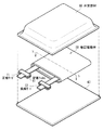
図1は、本技術の一実施形態における二次電池用活物質の断面構成を表しており、図2は、図1に示した二次電池用活物質の表面のSEM写真である。なお、図3は、比較例における二次電池用活物質の表面のSEM写真である。
<1. Secondary battery active material>
FIG. 1 illustrates a cross-sectional configuration of an active material for a secondary battery according to an embodiment of the present technology, and FIG. 2 is an SEM photograph of the surface of the active material for a secondary battery illustrated in FIG. FIG. 3 is an SEM photograph of the surface of the active material for a secondary battery in the comparative example.
ここで説明する二次電池用活物質は、例えば、リチウムイオン二次電池などの電極に用いられるものである。ただし、二次電池用活物質は、正極活物質として正極に用いられてもよいし、負極活物質として負極に用いられてもよい。 The active material for a secondary battery described here is used for an electrode of a lithium ion secondary battery, for example. However, the active material for secondary batteries may be used for a positive electrode as a positive electrode active material, and may be used for a negative electrode as a negative electrode active material.
[活物質の構成]
二次電池用活物質である活物質1は、図1に示したように、粒子状の中心部2と、その中心部2の表面に設けられた被覆部3とを含んでいる。
[Composition of active material]
As shown in FIG. 1, the active material 1 that is an active material for a secondary battery includes a particulate central portion 2 and a covering portion 3 provided on the surface of the central portion 2.
中心部2が被覆部3により被覆されている活物質1の構成を確認するためには、例えば、SEMなどの顕微鏡を用いて活物質1の断面を観察すればよい。この他、例えば、X線回折法(XRD:X-Ray Diffraction )、X線光電子分光法(XPS:X-ray Photoelectron Spectroscopy)およびエネルギー分散型X線分析法(EDX:Energy Dispersive X-ray spectroscopy)などのいずれか1種類または2種類以上を用いて活物質1を分析してもよい。 In order to confirm the configuration of the active material 1 in which the central portion 2 is covered with the covering portion 3, for example, a cross section of the active material 1 may be observed using a microscope such as an SEM. In addition, for example, X-ray diffraction (XRD), X-ray photoelectron spectroscopy (XPS), and energy dispersive X-ray spectroscopy (EDX). The active material 1 may be analyzed using any one type or two or more types.
なお、電極中において活物質1が結着剤および導電剤などの他の材料と混合されている場合には、例えば、遠心分離機などを用いて活物質1を他の材料から分離すればよい。また、電極を用いた二次電池の完成後においては、後述するように、非対向領域の活物質1を観察および分析することが好ましい。 In addition, when the active material 1 is mixed with other materials such as a binder and a conductive agent in the electrode, the active material 1 may be separated from the other materials using, for example, a centrifuge. . Moreover, after the completion of the secondary battery using the electrodes, it is preferable to observe and analyze the active material 1 in the non-facing region, as will be described later.
[中心部]
中心部2は、活物質1の内郭部分であり、主に、電極反応物質を吸蔵放出する機能を担っている。「電極反応物質」とは、例えば、リチウムイオン二次電池ではリチウム(リチウムイオン)である。この中心部2は、電極反応物質を吸蔵放出可能である活物質材料を含んでおり、その活物質材料は、ケイ素(Si)を構成元素として含んでいる。エネルギー密度が高いため、高い電池容量が得られるからである。ただし、活物質材料は、ケイ素と共に、1種類または2種類以上の他の元素を構成元素として含んでいてもよい。
[Central part]
The central portion 2 is an inner portion of the active material 1 and mainly has a function of occluding and releasing the electrode reactant. The “electrode reactant” is, for example, lithium (lithium ion) in a lithium ion secondary battery. The central portion 2 includes an active material that can occlude and release electrode reactants, and the active material includes silicon (Si) as a constituent element. This is because a high battery capacity can be obtained because the energy density is high. However, the active material may contain one kind or two or more kinds of other elements as constituent elements together with silicon.
活物質材料は、ケイ素を構成元素として含む材料のいずれか1種類または2種類以上であれば、特に限定されない。すなわち、活物質材料は、ケイ素の単体、化合物および合金のいずれでもよい。活物質材料がケイ素を構成元素として含んでいることで、その活物質材料の種類に依存せずに高いエネルギー密度が得られるからである。ここで説明する「単体」とは、あくまで一般的な意味における単体であり、必ずしも純度100%を意味しているわけではない。このため、ケイ素の単体は、微量の不純物を含んでいてもよい。 The active material is not particularly limited as long as it is any one or more of materials containing silicon as a constituent element. That is, the active material may be any of silicon simple substance, compound and alloy. This is because when the active material contains silicon as a constituent element, a high energy density can be obtained without depending on the type of the active material. The “simple substance” described here is a simple substance in a general sense, and does not necessarily mean 100% purity. For this reason, the simple substance of silicon may contain a trace amount of impurities.
ケイ素の合金は、例えば、ケイ素以外の構成元素として、スズ(Sn)、ニッケル(Ni)、銅(Cu)、鉄(Fe)、コバルト(Co)、マンガン(Mn)、亜鉛(Zn)、インジウム(In)、銀(Ag)、チタン(Ti)、ゲルマニウム(Ge)、ビスマス(Bi)、アンチモン(Sb)およびクロム(Cr)などのいずれか1種類または2種類以上を含んでいる。ケイ素の化合物は、例えば、ケイ素以外の構成元素として、炭素および酸素などのいずれか1種類または2種類以上を含んでいる。なお、ケイ素の化合物は、例えば、ケイ素以外の構成元素として、ケイ素の合金について説明した元素のいずれか1種類または2種類以上を含んでいてもよい。 Silicon alloys include, for example, tin (Sn), nickel (Ni), copper (Cu), iron (Fe), cobalt (Co), manganese (Mn), zinc (Zn), and indium as constituent elements other than silicon. One or more of (In), silver (Ag), titanium (Ti), germanium (Ge), bismuth (Bi), antimony (Sb), chromium (Cr) and the like are included. The compound of silicon contains, for example, any one or more of carbon and oxygen as constituent elements other than silicon. The silicon compound may contain, for example, any one or more of the elements described for the silicon alloy as a constituent element other than silicon.
ケイ素の合金およびケイ素の化合物の具体例は、SiB4 、SiB6 、Mg2 Si、Ni2 Si、TiSi2 、MoSi2 、CoSi2 、NiSi2 、CaSi2 、CrSi2 、Cu5 Si、FeSi2 、MnSi2 、NbSi2 、TaSi2 、VSi2 、WSi2 、ZnSi2 、SiC、Si3 N4 、Si2 N2 O、SiOw (0<w≦2)およびLiSiOなどである。 Specific examples of silicon alloys and silicon compounds are SiB 4 , SiB 6 , Mg 2 Si, Ni 2 Si, TiSi 2 , MoSi 2 , CoSi 2 , NiSi 2 , CaSi 2 , CrSi 2 , Cu 5 Si, FeSi 2. , MnSi 2 , NbSi 2 , TaSi 2 , VSi 2 , WSi 2 , ZnSi 2 , SiC, Si 3 N 4 , Si 2 N 2 O, SiO w (0 <w ≦ 2) and LiSiO.
活物質材料は、ケイ素と共に酸素(O)を構成元素として含んでいることが好ましい。充放電時(特に初期の充放電時)において不可逆容量が減少するため、より高い電池容量が得られるからである。具体的には、活物質材料は、SiOw (0<w≦2)で表される酸化ケイ素を含んでいることが好ましい。 The active material preferably contains oxygen (O) as a constituent element together with silicon. This is because the irreversible capacity decreases during charging / discharging (especially during initial charging / discharging), and thus higher battery capacity can be obtained. Specifically, the active material preferably contains silicon oxide represented by SiO w (0 <w ≦ 2).
酸化ケイ素の組成(SiOw )は、上記した条件(0<w≦2)を満たしていれば、特に限定されない。中でも、wは、0.3≦w<1.9を満たしていることが好ましい。中心部2において電極反応物質が吸蔵放出されやすくなるからである。 The composition of silicon oxide (SiO w ) is not particularly limited as long as it satisfies the above condition (0 <w ≦ 2). Among these, w preferably satisfies 0.3 ≦ w <1.9. This is because the electrode reactant is easily occluded and released in the central portion 2.
酸化ケイ素を含む中心部2では、その酸化ケイ素の構成元素であるケイ素および酸素がどのように分布していてもよい。具体的には、ケイ素の存在量(原子量)は、中心部2の表面(最表面)から内部(中心)に向かう方向において一定でもよいし、その方向において変化(増加または減少)していてもよい。ケイ素の原子量が変化している場合には、その原子量が連続的に変化(次第に増加または減少)していてもよいし、その原子量が断続的に変化(急激に増加または減少)していてもよい。 In the central part 2 containing silicon oxide, silicon and oxygen which are constituent elements of the silicon oxide may be distributed in any way. Specifically, the abundance (atomic weight) of silicon may be constant in the direction from the surface (outermost surface) of the central portion 2 to the inside (center) or may change (increase or decrease) in that direction. Good. When the atomic weight of silicon is changing, the atomic weight may be continuously changing (gradually increasing or decreasing), or the atomic weight may be intermittently changing (rapidly increasing or decreasing). Good.
中心部2の表面、すなわち中心部2と被覆部3との界面において、酸素の原子量に対するケイ素の原子量の割合(原子割合:Si/O)は、特に限定されない。中でも、原子割合は、75原子%以下であることが好ましく、30原子%〜70原子%であることがより好ましい。中心部2において電極反応物質が吸蔵放出されやすくなると共に、その中心部2の電気抵抗が低下するからである。 The ratio of the atomic weight of silicon to the atomic weight of oxygen (atomic ratio: Si / O) on the surface of the central portion 2, that is, the interface between the central portion 2 and the covering portion 3, is not particularly limited. Especially, it is preferable that an atomic ratio is 75 atomic% or less, and it is more preferable that it is 30 atomic%-70 atomic%. This is because the electrode reactant is easily occluded and released in the central portion 2 and the electrical resistance of the central portion 2 is reduced.
詳細には、原子割合が30原子%よりも小さいと、酸素の原子量がケイ素の原子量に対して大きくなりすぎるため、電気抵抗が増加しやすくなる。一方、原子割合が75原子%(または70原子%)よりも大きいと、ケイ素の原子量が酸素の原子量に対して大きくなりすぎるため、中心部2において電極反応物質は吸蔵放出されやすいが、充放電を繰り返すとケイ素が劣化(表面劣化)しやすくなる。 Specifically, when the atomic ratio is less than 30 atomic%, the atomic weight of oxygen becomes too large with respect to the atomic weight of silicon, so that the electrical resistance tends to increase. On the other hand, when the atomic ratio is larger than 75 atomic% (or 70 atomic%), the atomic weight of silicon becomes too large with respect to the atomic weight of oxygen, so that the electrode reactant is easily occluded and released in the central portion 2. If it repeats, it will become easy to deteriorate silicon (surface deterioration).
この原子割合は、原子割合(原子%)=(ケイ素の原子量/酸素の原子量)×100により算出される。ケイ素および酸素のそれぞれの原子量を測定するためには、例えば、エネルギー分散型X線分光法(TEM:Transmission Electron Microscope/EDX)を用いて中心部2の表面を分析すればよい。TEM装置は、例えば、日本電子株式会社製のJEM−2100F、EDX装置は日本電子株式会社製のJED−2300Tとする。測定条件は、例えば、加速電圧=200kV、ビーム電流=240pA、ビーム径=0.15mm、分析(積算)時間=30秒である。 This atomic ratio is calculated by atomic ratio (atomic%) = (atomic weight of silicon / atomic weight of oxygen) × 100. In order to measure the atomic weight of each of silicon and oxygen, for example, the surface of the central portion 2 may be analyzed using energy dispersive X-ray spectroscopy (TEM: Transmission Electron Microscope / EDX). The TEM device is, for example, JEM-2100F manufactured by JEOL Ltd., and the EDX device is JED-2300T manufactured by JEOL Ltd. The measurement conditions are, for example, acceleration voltage = 200 kV, beam current = 240 pA, beam diameter = 0.15 mm, and analysis (integration) time = 30 seconds.
酸化ケイ素の組成(SiOw )を確認するためには、中心部2の酸化度(原子比wの値)を調べればよい。この場合には、例えば、中心部2を得るために、フッ化水素(HF)などの酸を用いて被覆部3を溶解除去してもよい。 In order to confirm the composition (SiO w ) of silicon oxide, the degree of oxidation (the value of the atomic ratio w) of the central portion 2 may be examined. In this case, for example, in order to obtain the central portion 2, the covering portion 3 may be dissolved and removed using an acid such as hydrogen fluoride (HF).
なお、活物質材料は、金属元素のいずれか1種類または2種類以上を構成元素として含んでいることが好ましい。中心部2の電気抵抗が低下するからである。これにより、中心部2が高抵抗の酸化ケイ素を含んでいても、活物質1全体の電気抵抗が低く抑えられる。この中心部2において、金属元素は、ケイ素とは別個に(遊離状態で)存在していてもよいし、ケイ素と合金または化合物を形成していてもよい。この金属元素を含んでいる中心部2の化学的状態(金属原子の結合状態など)に関しては、例えば、EDXなどを用いて確認可能である。 Note that the active material preferably contains any one or more of metal elements as constituent elements. This is because the electrical resistance of the central portion 2 is lowered. Thereby, even if the center part 2 contains high resistance silicon oxide, the electrical resistance of the whole active material 1 is suppressed low. In the central portion 2, the metal element may exist separately (in a free state) from silicon, or may form an alloy or a compound with silicon. The chemical state (such as the bonding state of metal atoms) of the central portion 2 containing the metal element can be confirmed using, for example, EDX.
金属元素の種類は、特に限定されないが、例えば、鉄(Fe)、アルミニウム(Al)、カルシウム(Ca)、マンガン(Mn)、クロム(Cr)、マグネシウム(Mg)、ニッケル(Ni)、ホウ素(B)、チタン(Ti)、バナジウム(V)、コバルト(Co)、銅(Cu)、ゲルマニウム(Ge)、イットリウム(Y)、ジルコニウム(Zr)、モリブデン(Mo)、銀(Ag)、インジウム(In)、スズ(Sn)、アンチモン(Sb)、タンタル(Ta)、タングステン(W)、鉛(Pb)、ランタン(La)、セシウム(Ce)、プルトニウム(Pr)およびネオジム(Nd)などのいずれか1種類または2種類以上であることが好ましい。中でも、鉄、アルミニウム、カルシウム、マンガン、クロム、マグネシウムおよびニッケルのいずれか1種類または2種類以上が好ましい。中心部2の電気抵抗が効果的に低下するからである。 The type of metal element is not particularly limited. For example, iron (Fe), aluminum (Al), calcium (Ca), manganese (Mn), chromium (Cr), magnesium (Mg), nickel (Ni), boron ( B), titanium (Ti), vanadium (V), cobalt (Co), copper (Cu), germanium (Ge), yttrium (Y), zirconium (Zr), molybdenum (Mo), silver (Ag), indium ( In), tin (Sn), antimony (Sb), tantalum (Ta), tungsten (W), lead (Pb), lanthanum (La), cesium (Ce), plutonium (Pr), neodymium (Nd), etc. It is preferable that it is 1 type or 2 types or more. Among these, any one or two or more of iron, aluminum, calcium, manganese, chromium, magnesium and nickel is preferable. This is because the electrical resistance of the central portion 2 is effectively reduced.
中心部2の結晶状態は、特に限定されず、結晶性でもよいし、非結晶性でもよい。中でも、結晶状態は、非結晶性または低結晶性であることが好ましい。充放電時において活物質1が膨張収縮しても、その活物質1が破損(割れ等)しにくくなるからである。 The crystalline state of the central portion 2 is not particularly limited, and may be crystalline or non-crystalline. Among these, the crystalline state is preferably amorphous or low crystalline. This is because even if the active material 1 expands and contracts during charge and discharge, the active material 1 is less likely to be damaged (cracked or the like).
詳細には、「低結晶性」とは、結晶領域(結晶粒)が非結晶領域の中に点在している結晶状態を意味している。より具体的には、高角散乱暗視野走査型透過電子顕微鏡(HAADF STEM:High-Angle Annular Dark-field Scanning Transmission Electron Microscopy )などを用いて中心部2の断面または表面を観察した場合において、結晶領域(結晶粒)と非結晶領域とが混在している結晶状態を意味している。TEM写真から非結晶領域と結晶領域とが混在している状態を確認できれば、その中心部2の結晶状態は低結晶性である。なお、非結晶領域と結晶領域とが混在している場合において、その結晶領域は、粒状の輪郭を有する領域(結晶粒)として観察される。この結晶粒の内部には、結晶性に起因する縞状の模様(結晶格子縞)が観察されるため、その結晶粒を非結晶領域から識別できる。これに対して、「非結晶性」とは、いわゆる非晶質と同義であり、HAADF STEMなどを用いて中心部2を観察した場合において、非結晶領域だけが存在しており、結晶領域が存在していない結晶状態を意味している。なお、観察時の倍率は、特に限定されないが、例えば、1.2×10⁶ 倍とする。 Specifically, “low crystallinity” means a crystal state in which crystal regions (crystal grains) are scattered in non-crystalline regions. More specifically, when the cross section or surface of the central portion 2 is observed using a high-angle scattering dark-field scanning transmission electron microscope (HAADF STEM), the crystal region It means a crystal state in which (crystal grains) and an amorphous region are mixed. If it can be confirmed from the TEM photograph that the amorphous region and the crystalline region are mixed, the crystalline state of the central portion 2 is low crystalline. Note that in the case where a non-crystalline region and a crystalline region are mixed, the crystalline region is observed as a region (crystal grain) having a granular outline. Since a stripe pattern (crystal lattice stripe) due to crystallinity is observed inside the crystal grain, the crystal grain can be identified from the amorphous region. On the other hand, “non-crystalline” is synonymous with so-called amorphous, and when the central portion 2 is observed using a HAADF STEM or the like, only the non-crystalline region exists, and the crystalline region is It means a crystalline state that does not exist. Note that the magnification at the time of observation is not particularly limited, but is 1.2 × 10 6 times, for example.
非結晶性と低結晶性との違いに関しては、TEM写真に基づいて判断できる。中心部2の結晶状態が非結晶性である場合には、非結晶領域だけが存在しており、結晶領域(結晶格子縞を有する結晶粒)が存在していない。これに対して、中心部2の結晶状態が低結晶性である場合には、非結晶領域の中に結晶粒が点在している。この結晶粒は、ケイ素の格子面間隔dに応じた所定の間隔の結晶格子縞を有しているため、その周辺の非結晶領域から明確に区別される。 The difference between non-crystallinity and low crystallinity can be judged based on a TEM photograph. When the crystal state of the central portion 2 is non-crystalline, only the non-crystalline region exists, and the crystal region (crystal grains having crystal lattice stripes) does not exist. On the other hand, when the crystal state of the central portion 2 is low crystalline, crystal grains are scattered in the amorphous region. Since the crystal grains have crystal lattice stripes of a predetermined interval corresponding to the lattice plane interval d of silicon, the crystal grains are clearly distinguished from the surrounding amorphous regions.
中心部2の結晶状態が低結晶性である場合において、その結晶性の程度は、特に限定されない。中でも、ケイ素の(111)面および(220)面に起因する結晶粒の平均面積占有率は、35%以下であることが好ましいと共に、その結晶粒の平均粒径は、30nm以下であることが好ましい。充放電時において活物質1が膨張収縮しにくくなるため、より破損しにくくなるからである。 When the crystal state of the central portion 2 is low crystallinity, the degree of crystallinity is not particularly limited. Among them, the average area occupation ratio of crystal grains due to the (111) plane and (220) plane of silicon is preferably 35% or less, and the average grain size of the crystal grains is 30 nm or less. preferable. This is because the active material 1 is less likely to expand and contract during charging and discharging, and thus is less likely to be damaged.
この平均面積占有率の算出手順は、以下の通りである。最初に、HAADF STEMを用いて中心部2の断面を観察して、TEM写真を得る。この場合には、観察倍率=1.2×10⁶ 倍、観察エリア=65.6nm×65.7nmとする。続いて、結晶格子縞の有無および格子面間隔dの値などを調べて、ケイ素の(111)面に起因する結晶粒および(220)面に起因する結晶粒が存在する領域を特定したのち、それらの結晶粒の輪郭をTEM写真中に描画する。ケイ素の(111)面に起因する結晶粒とは、格子面間隔d=0.31nmの結晶格子縞を有する結晶領域であり、ケイ素の(220)面に起因する結晶粒とは、格子面間隔d=0.19nmの結晶格子縞を有する結晶領域である。続いて、各結晶粒の面積を算出したのち、面積占有率(%)=(結晶粒の面積の和/観察エリアの面積)×100を算出する。これらの輪郭の描画および面積占有率の算出に関しては、人為的に行ってもよいし、専用の処理ソフトなどを用いて機械的に行ってもよい。最後に、40エリアにおいて面積占有率の算出作業を繰り返したのち、各エリアにおいて算出した面積占有率の平均値(平均面積占有率)を算出する。 The procedure for calculating the average area occupancy is as follows. First, a cross section of the central portion 2 is observed using a HAADF STEM to obtain a TEM photograph. In this case, the observation magnification = 1.2 × 10 6 times and the observation area = 65.6 nm × 65.7 nm. Subsequently, after checking the presence / absence of crystal lattice fringes and the value of the lattice spacing d, etc., the region where the crystal grains due to the (111) plane and the crystal grains due to the (220) plane exist is specified. The outline of the crystal grains is drawn in a TEM photograph. The crystal grain resulting from the (111) plane of silicon is a crystal region having crystal lattice stripes having a lattice spacing d = 0.31 nm, and the crystal grain originating from the (220) plane of silicon is the lattice spacing d. = A crystal region having a crystal lattice fringe of 0.19 nm. Subsequently, after calculating the area of each crystal grain, the area occupation ratio (%) = (sum of crystal grain area / area of observation area) × 100 is calculated. The drawing of the outline and the calculation of the area occupancy may be performed manually or mechanically using dedicated processing software. Finally, after repeating the area occupancy calculation operation in 40 areas, the average value of the area occupancy calculated in each area (average area occupancy) is calculated.
結晶粒の平均粒径の算出手順は、エリアごとに平均粒径を測定したのち、その平均粒径の平均値(最終的な平均粒径)を算出することを除き、平均面積占有率を算出した場合と同様である。なお、結晶粒の粒径を測定する場合には、例えば、結晶粒の輪郭を円に変換(結晶粒の輪郭により画定される形状と同等の面積を有する円を特定)したのち、その円の直径を粒径とする。この平均粒径の算出は、平均面積占有率を算出した場合と同様に、人為的でも機械的でもよい。 The procedure for calculating the average grain size of crystal grains is to calculate the average area occupancy rate, except that after measuring the average grain size for each area, the average value of the average grain size (final average grain size) is calculated. It is the same as that. When measuring the grain size of a crystal grain, for example, after converting the outline of the crystal grain into a circle (specifying a circle having an area equivalent to the shape defined by the outline of the crystal grain), Let the diameter be the particle size. The calculation of the average particle diameter may be artificial or mechanical, as in the case of calculating the average area occupancy.
中心部2の平均粒径(メジアン径D50)は、特に限定されないが、中でも、0.1μm〜20μmであることが好ましい。充放電時において活物質1がより破損しにくくなると共に、高い安全性が得られるからである。詳細には、D50が0.1μmよりも小さいと、中心部2の表面積(反応面積)が増加しすぎることに起因して、電解液の分解反応などが促進されるため、安全性が低下しやすくなる。一方、D50が20μmよりも大きいと、充電時の膨張に起因して活物質1が破損しやすくなると共に、電極の作製工程において活物質1を含むスラリーを塗布しにくくなる。 The average particle size (median diameter D50) of the central portion 2 is not particularly limited, but is preferably 0.1 μm to 20 μm. This is because the active material 1 is less likely to be damaged during charging and discharging, and high safety is obtained. Specifically, when D50 is smaller than 0.1 μm, the surface area (reaction area) of the central portion 2 is excessively increased, so that the decomposition reaction of the electrolytic solution is promoted and the safety is lowered. It becomes easy. On the other hand, when D50 is larger than 20 μm, the active material 1 is likely to be damaged due to expansion during charging, and it becomes difficult to apply the slurry containing the active material 1 in the electrode manufacturing process.
中心部2の平均粒径を調べる場合には、その中心部2自体の平均粒径を測定してもよいし、活物質1を用いて中心部2の平均粒径を算出してもよい。活物質1を用いる場合には、例えば、レーザ解析(回折)から活物質1の平均粒径(メジアン径D50)を求めたのち、その平均粒径から後述する被覆部3の平均厚さを差し引いた値を求めて、その値を中心部2の平均粒径とすればよい。なお、被覆部3の平均厚さが極めて薄く、具体的には約200nm以下である場合には、レーザ解析から求められた活物質1の平均粒径が中心部2の平均粒径にほぼ一致すると考えられる。 When examining the average particle size of the central portion 2, the average particle size of the central portion 2 itself may be measured, or the average particle size of the central portion 2 may be calculated using the active material 1. When the active material 1 is used, for example, after obtaining the average particle diameter (median diameter D50) of the active material 1 from laser analysis (diffraction), the average thickness of the covering portion 3 described later is subtracted from the average particle diameter. What is necessary is just to obtain | require the value and let the value be the average particle diameter of the center part 2. In addition, when the average thickness of the covering portion 3 is extremely thin, specifically, about 200 nm or less, the average particle size of the active material 1 obtained from the laser analysis is almost equal to the average particle size of the central portion 2. I think that.
なお、中心部2では、構成元素であるケイ素のうちの少なくとも一部が未充電状態において電極反応物質と合金化していることが好ましい。言い替えれば、未充電状態の中心部2において、その中心部2に電極反応物質が既に吸蔵(いわゆるプレドープ)されていることが好ましい。初期の充放電時において不可逆容量が減少するため、より高い電池容量が得られるからである。この中心部2がプレドープされているか否かに関しては、後述するように、完成後の二次電池において非対向領域の活物質1を調べることが好ましい。 In the central portion 2, it is preferable that at least a part of the constituent element silicon is alloyed with the electrode reactant in an uncharged state. In other words, it is preferable that the electrode reactive substance is already occluded (so-called pre-dope) in the central portion 2 in the uncharged central portion 2. This is because the irreversible capacity is reduced during the initial charge / discharge, so that a higher battery capacity can be obtained. As to whether or not the central portion 2 is pre-doped, it is preferable to examine the active material 1 in the non-facing region in the completed secondary battery, as will be described later.
中でも、活物質1がリチウムイオン二次電池に用いられる場合には、中心部2は、ケイ酸リチウムを含んでいることが好ましい。中心部2がプレドープされた状態になるため、上記したように不可逆容量が減少するからである。 Especially, when the active material 1 is used for a lithium ion secondary battery, it is preferable that the center part 2 contains lithium silicate. This is because the irreversible capacity is reduced as described above because the central portion 2 is in a pre-doped state.
[被覆部]
被覆部3は、活物質1の外郭部分であり、主に、中心部2を物理的および化学的に保護する機能を担っている。この被覆部3は、導電性材料を含んでおり、その導電性材料は、炭素(C)および水素(H)を構成元素として含んでいる。被覆部3が炭素を構成元素として含んでいるのは、高い導電性が得られるため、活物質1全体の電気抵抗が低下するからである。これにより、中心部2が高抵抗の酸化ケイ素を含んでいても、活物質1全体の電気抵抗が低く抑えられる。ただし、被覆部3は、炭素および水素と共に、1種類または2種類以上の他の元素を構成元素として含んでいてもよい。
[Coating]
The covering portion 3 is an outer portion of the active material 1 and mainly has a function of physically and chemically protecting the central portion 2. The covering portion 3 contains a conductive material, and the conductive material contains carbon (C) and hydrogen (H) as constituent elements. The reason why the covering portion 3 contains carbon as a constituent element is that high electrical conductivity is obtained, and thus the electrical resistance of the active material 1 as a whole decreases. Thereby, even if the center part 2 contains high resistance silicon oxide, the electrical resistance of the whole active material 1 is suppressed low. However, the coating | coated part 3 may contain 1 type, or 2 or more types of other elements as a structural element with carbon and hydrogen.
なお、被覆部3は、中心部2の表面のうちの少なくとも一部に設けられていればよい。すなわち、被覆部3は、中心部2の表面の一部だけを被覆していてもよいし、その表面の全部を被覆していてもよい。前者の場合には、中心部2の表面において、被覆部3が複数の場所に存在していてもよい。また、被覆部3は、単層でもよいし、多層でもよい。 In addition, the coating | coated part 3 should just be provided in at least one part of the surface of the center part 2. FIG. That is, the covering portion 3 may cover only a part of the surface of the central portion 2 or may cover the entire surface. In the former case, the covering portion 3 may exist at a plurality of locations on the surface of the central portion 2. The covering portion 3 may be a single layer or a multilayer.
この被覆部3は、上記したように、炭素および水素を構成元素として含んでいるため、炭素成分および水素成分と共に炭化水素成分を含んでいる。この被覆部3に含まれている炭化水素成分の組成(炭素と水素との結合状態)は、被覆部3の反応性との関係において適正化されている。 As described above, since the covering portion 3 includes carbon and hydrogen as constituent elements, the covering portion 3 includes a hydrocarbon component together with the carbon component and the hydrogen component. The composition of the hydrocarbon component (bonded state of carbon and hydrogen) contained in the covering portion 3 is optimized in relation to the reactivity of the covering portion 3.
具体的には、飛行時間型二次イオン質量分析法(TOF−SIMS)を用いた被覆部3の正イオン分析により、Cx Hy (xおよびyは2≦x≦6および3≦y≦9を満たす。)で表される正イオンのいずれか1種類または2種類以上が検出される。被覆部3の正イオン分析により上記した正イオンが検出されるのは、その被覆部3の表面における反応性が低減するからである。これにより、電解液の分解反応が抑制されると共に、電極反応物質の吸蔵放出を阻害する不可逆反応(副反応)も抑制される。なお、上記したxの値が6よりも大きくなると、被覆部3が化学的に不安定になるため、中心部2に対する被覆部3の密着性が極端に低下してしまう。 Specifically, C x is determined by positive ion analysis of the covering portion 3 using time-of-flight secondary ion mass spectrometry (TOF-SIMS). Any one type or two or more types of positive ions represented by H y (x and y satisfy 2 ≦ x ≦ 6 and 3 ≦ y ≦ 9) are detected. The reason why the positive ions are detected by the positive ion analysis of the covering portion 3 is that the reactivity on the surface of the covering portion 3 is reduced. Thereby, the decomposition reaction of the electrolytic solution is suppressed, and the irreversible reaction (side reaction) that inhibits the storage and release of the electrode reactant is also suppressed. In addition, since the coating | coated part 3 will become chemically unstable when the value of x mentioned above becomes larger than 6, the adhesiveness of the coating | coated part 3 with respect to the center part 2 will fall extremely.
以下では、上記した組成条件を満たす正イオンを「特定イオン」、その組成条件を満たさない正イオンを「他イオン」とそれぞれ呼称する。 Hereinafter, positive ions that satisfy the above-described composition condition are referred to as “specific ions”, and positive ions that do not satisfy the composition condition are referred to as “other ions”.
特定イオンの種類は、上記した組成条件を満たしていれば特に限定されないが、例えば、C2 H3 、C2 H4 、C2 H5 、C3 H5 、C3 H7 、C4 H8 、C4 H9 、C5 H7 およびC6 H5 などのいずれか1種類または2種類以上である。ただし、上記した特定イオンの種類は、あくまで一例であり、比較的検出強度が高い正イオンのいくつかを列挙しているにすぎない。このため、上記した組成条件を満たす正イオンであれば、上記以外の他の正イオンでもよい。これに対して、他イオンは、例えば、C、CH2 およびCH3 などのいずれか1種類または2種類以上である。 Type of the specific ion is not particularly limited if they meet the composition conditions described above, for example, C 2 H 3 , C 2 H 4 , C 2 H 5 , C 3 H 5, C 3 H 7, C 4 H 8 , C 4 H 9, C 5 H 7 and C 6 It is one, or two or more of such H 5. However, the types of specific ions described above are merely examples, and only a few positive ions with relatively high detection intensity are listed. For this reason, other positive ions than those described above may be used as long as they satisfy the above-described composition conditions. On the other hand, the other ions are, for example, one kind or two kinds or more of C, CH 2 and CH 3 .
ここで、正イオン分析に用いるTOF−SIMS装置は、例えば、ION−TOF社製のTOF−SIMS Vとする。分析条件は、一次イオン種=Bi3+、イオン銃加速電圧=25kV、パンチングモード、照射イオン電流=0.3pA(パルスモードでの計測)、質量範囲=1amu〜800amu、走査範囲=200μm×200μmとする。 Here, the TOF-SIMS apparatus used for positive ion analysis is, for example, TOF-SIMS V manufactured by ION-TOF. Analysis conditions are as follows: primary ion species = Bi 3+ , ion gun acceleration voltage = 25 kV, punching mode, irradiation ion current = 0.3 pA (measurement in pulse mode), mass range = 1 amu to 800 amu, scanning range = 200 μm × 200 μm And
特定イオンが検出されるか否かを調べるためには、例えば、複数の正イオンに起因するピークを含むTOF−SIMSスペクトル(横軸=質量、縦軸=強度)を得ればよい。各ピークの検出位置(質量)から正イオンの種類を特定することで、特定イオンが検出されたか否かを判断すればよい。 In order to investigate whether or not specific ions are detected, for example, a TOF-SIMS spectrum (horizontal axis = mass, vertical axis = intensity) including peaks caused by a plurality of positive ions may be obtained. What is necessary is just to judge whether the specific ion was detected by specifying the kind of positive ion from the detection position (mass) of each peak.
被覆部3の正イオン分析により特定イオンが検出されれば、その特定イオンの検出強度は、特に限定されない。中でも、特定イオンのうち、C2 H3 、C2 H5 およびC3 H5 のそれぞれで表される正イオンの検出強度の総和D1と、C(Cx Hy においてx=1およびy=0)の検出強度D2との比D1/D2は、1.25以上であることが好ましく、50以上であることがより好ましい。また、C2 H3 、C2 H5 およびC3 H5 のそれぞれで表される正イオンの検出強度の総和D1と、CHz (zは0≦z≦3を満たす。)で表される正イオンの検出強度の総和D3との比D1/D3は、1よりも大きいことが好ましい。いずれの場合においても、被覆部3の表面における反応性がより低減するからである。特に、比D1/D2が50以上になると、後述する活物質1を含むスラリーの混合状態(活物質1の分散性など)が良好になるため、塗布面が円滑になると共に塗布厚さが均一になる。なお、CHz (zは0≦z≦3を満たす。)で表される正イオンの種類は、C、CH、CH2 およびCH3 などのいずれか1種類または2種類以上である。 If specific ions are detected by positive ion analysis of the covering portion 3, the detection intensity of the specific ions is not particularly limited. Among them, among the specific ions, C 2 H 3 , C 2 H 5 and C 3 A sum D1 of detected intensities of positive ions represented by H 5 and C (C x The ratio D1 / D2 of the detected intensity D2 of x = 1 and y = 0) in H y is preferably 1.25 or more, and more preferably 50 or more. C 2 H 3 , C 2 H 5 and C 3 Ratio D1 / D3 between the sum D1 of positive ion detection intensities represented by each of H 5 and the sum D3 of positive ion detection intensities represented by CH z (z satisfies 0 ≦ z ≦ 3) Is preferably greater than 1. This is because in any case, the reactivity on the surface of the covering portion 3 is further reduced. In particular, when the ratio D1 / D2 is 50 or more, the mixed state of the slurry containing the active material 1 described later (such as dispersibility of the active material 1) becomes good, so that the coating surface becomes smooth and the coating thickness is uniform. become. Note that the type of positive ions represented by CH z (z satisfies 0 ≦ z ≦ 3) is one or more of C, CH, CH 2 and CH 3 .
TOF−SIMSにより特定イオンが検出される被覆部3の表面は、特徴的な構造を有する。具体的には、特定イオンが検出される被覆部3の表面には、図2に示したように、その特定イオンに起因した微細な凹凸構造が形成される。この場合には、活物質1に対する結着剤などの接着性が向上するため、その活物質1が結着剤などから剥離しにくくなる。これに伴い、後述するように活物質1と共に結着剤などを含む電極を巻回させる際に、その電極が崩壊しにくくなるため、いわゆる電極の巻回性が向上する。これに対して、特定イオンが検出されない被覆部3の表面は、図3に示したように、特定イオンに起因した微細な凹凸構造が形成されないため、ほぼ平坦になる。 The surface of the covering part 3 where specific ions are detected by TOF-SIMS has a characteristic structure. Specifically, as shown in FIG. 2, a fine concavo-convex structure resulting from the specific ions is formed on the surface of the covering portion 3 where the specific ions are detected. In this case, since the adhesiveness such as the binder to the active material 1 is improved, the active material 1 is difficult to peel from the binder or the like. Accordingly, when an electrode containing a binder and the like is wound together with the active material 1 as will be described later, the electrode is less likely to collapse, so that the so-called electrode winding property is improved. On the other hand, the surface of the covering portion 3 from which specific ions are not detected becomes substantially flat because a fine uneven structure due to specific ions is not formed as shown in FIG.
被覆部3の平均厚さは、特に限定されないが、中でも、できるだけ薄いことが好ましく、具体的には500nm以下であることが好ましい。中心部2において電極反応物質が吸蔵放出されやすくなるからである。ただし、被覆部3の平均厚さは、20nm以上であることが好ましい。被覆部3が薄すぎると、充放電時において活物質1が割れやすくなるからである。 Although the average thickness of the coating | coated part 3 is not specifically limited, Especially, it is preferable that it is as thin as possible, and it is preferable that it is specifically 500 nm or less. This is because the electrode reactant is easily occluded and released in the central portion 2. However, the average thickness of the covering portion 3 is preferably 20 nm or more. This is because if the covering portion 3 is too thin, the active material 1 is liable to break during charging and discharging.
この被覆部3の平均厚さは、以下の手順により算出される。まず、SEMなどを用いて1個の活物質1を観察する。この観察時の倍率は、被覆部3の厚さを測定するために、中心部2と被覆部3との境界を目視で確認(決定)できる倍率が好ましい。続いて、任意の10点において被覆部3の厚さを測定したのち、その平均値(1個当たりの平均厚さT)を算出する。この場合には、できるだけ特定の場所周辺に集中せずに広く分散されるように測定位置を設定することが好ましい。続いて、SEMによる観察個数の総数が100個になるまで、上記した平均値の算出作業を繰り返す。最後に、100個の活物質1に関して算出された平均値(1個当たりの平均厚さ)の平均値(平均厚さの平均値)を算出して、被覆部3の平均厚さとする。 The average thickness of the covering portion 3 is calculated by the following procedure. First, one active material 1 is observed using SEM or the like. The magnification at the time of observation is preferably a magnification capable of visually confirming (determining) the boundary between the central portion 2 and the covering portion 3 in order to measure the thickness of the covering portion 3. Subsequently, after measuring the thickness of the covering portion 3 at arbitrary 10 points, the average value (average thickness T per piece) is calculated. In this case, it is preferable to set the measurement positions so that they are widely dispersed without concentrating around a specific place as much as possible. Subsequently, the above average value calculation operation is repeated until the total number of observations by SEM reaches 100. Finally, the average value (average thickness of the average thickness) of the average values (average thickness per one) calculated for the 100 active materials 1 is calculated and used as the average thickness of the covering portion 3.
中心部2に対する被覆部3の平均被覆率は、特に限定されないが、中でも、できるだけ大きいことが好ましく、具体的には30%以上(30%〜100%)であることが好ましい。被覆部3の表面における反応性が効果的に低減するからである。 Although the average coverage of the coating | coated part 3 with respect to the center part 2 is not specifically limited, Especially, it is preferable that it is as large as possible specifically, and it is preferable that it is 30% or more (30-100%). This is because the reactivity on the surface of the covering portion 3 is effectively reduced.
この被覆部3の平均被覆率は、以下の手順により算出される。まず、平均厚さを算出した場合と同様に、SEMなどを用いて1個の活物質1を観察する。この観察時の倍率は、中心部2のうち、被覆部3により被覆されている部分と被覆されていない部分とを目視で識別できる倍率が好ましい。続いて、中心部2の外縁(輪郭)のうち、被覆部3により被覆されている部分の長さと被覆されていない部分の長さとを測定する。そして、被覆率(1個当たりの被覆率:%)=(被覆部3により被覆されている部分の長さ/中心部2の外縁の長さ)×100を算出する。続いて、SEMによる観察個数の総数が100個になるまで、上記した被覆率の算出作業を繰り返す。最後に、100個の活物質1に関して算出された被覆率(1個当たりの被覆率)の平均値を算出して、被覆部3の平均被覆率とする。 The average coverage of the covering portion 3 is calculated by the following procedure. First, similarly to the case where the average thickness is calculated, one active material 1 is observed using SEM or the like. The magnification at the time of observation is preferably a magnification capable of visually distinguishing a portion covered by the covering portion 3 and a portion not covered from the center portion 2. Subsequently, the length of the portion covered by the covering portion 3 and the length of the portion not covered in the outer edge (contour) of the center portion 2 are measured. Then, the coverage ratio (coverage ratio per piece:%) = (length of the portion covered by the covering portion 3 / length of the outer edge of the central portion 2) × 100 is calculated. Subsequently, the above-described coverage calculation operation is repeated until the total number of observations by SEM reaches 100. Finally, the average value of the coverages (coverage per one) calculated for 100 active materials 1 is calculated as the average coverage of the covering portion 3.
ここで、一般的に、ラマンスペクトル法を用いて炭素材料を分析すると、その分析結果(ラマンスペクトル)では、黒鉛構造に由来するGバンドピークが1590cm-1近傍に検出されると共に、欠陥に由来するDバンドピークが1350cm-1近傍に検出される。このGバンドピークの強度IGとDバンドピークの強度IDとの比IG/IDは、G/D比とも呼ばれており、炭素材料の結晶状態(純度)を表す指標である。 Here, in general, when a carbon material is analyzed using the Raman spectrum method, the analysis result (Raman spectrum) shows that the G band peak derived from the graphite structure is detected in the vicinity of 1590 cm −1 and derived from the defect. A D band peak is detected in the vicinity of 1350 cm −1 . The ratio IG / ID between the intensity IG of the G band peak and the intensity ID of the D band peak is also called a G / D ratio, and is an index representing the crystal state (purity) of the carbon material.
炭素を構成元素として含む被覆部3の比IG/IDは、特に限定されないが、中でも、0.3〜3であることが好ましく、2前後であることがより好ましい。優れた結着性、導電性および変形性が得られるからである。 Although ratio IG / ID of the coating | coated part 3 containing carbon as a structural element is not specifically limited, Especially, it is preferable that it is 0.3-3, and it is more preferable that it is around 2. This is because excellent binding properties, conductivity, and deformability can be obtained.
詳細には、比IG/IDが0.3よりも小さいと、結着性が高くなるため、被覆部3同士の密着性および中心部2に対する被覆部3の密着性が向上する。しかしながら、導電性が低下すると共に硬くなるため、活物質1の膨張収縮に追随して被覆部3が膨張収縮しにくくなると共に十分な導電性が得られない可能性がある。一方、比IG/IDが3よりも大きいと、導電性が高くなると共に軟らかくなるため、活物質1の膨張収縮に追随して被覆部3が膨張収縮しやすくなると共に十分な導電性が得られる。しかしながら、結着性が低下するため、被覆部3同士の密着性および中心部2に対する被覆部3の密着性が低下する可能性がある。これに対して、比IG/IDが0.3〜3であると、被覆部3の結着性および導電性が高くなると共に、活物質1の膨張収縮に追随して被覆部3が膨張収縮しやすくなる。 Specifically, when the ratio IG / ID is smaller than 0.3, the binding property is increased, so that the adhesion between the covering parts 3 and the adhesion of the covering part 3 to the center part 2 are improved. However, since the conductivity decreases and becomes hard, the covering portion 3 hardly expands and contracts following the expansion and contraction of the active material 1, and sufficient conductivity may not be obtained. On the other hand, when the ratio IG / ID is larger than 3, the conductivity becomes high and the softness becomes soft, so that the covering portion 3 easily expands and contracts following the expansion and contraction of the active material 1, and sufficient conductivity is obtained. . However, since the binding property is lowered, the adhesion between the covering parts 3 and the adhesion of the covering part 3 to the central part 2 may be reduced. On the other hand, when the ratio IG / ID is 0.3 to 3, the binding property and conductivity of the covering portion 3 are increased, and the covering portion 3 is expanded and contracted following the expansion and contraction of the active material 1. It becomes easy to do.
ラマンスペクトル法を用いる場合には、例えば、分析対象物に対して、その分析対象物上の照射強度が0.3mWとなるようにレーザ光(波長=523nm)を照射すると共に、波数分解能が4cm-1であるラマン分光器を用いた。 When the Raman spectrum method is used, for example, the object is irradiated with laser light (wavelength = 523 nm) so that the irradiation intensity on the object is 0.3 mW, and the wave number resolution is 4 cm. A Raman spectrometer of -1 was used.
[活物質の製造方法]
この活物質1は、例えば、以下の手順により製造される。
[Method for producing active material]
This active material 1 is manufactured by the following procedures, for example.
最初に、電極反応物質を吸蔵放出可能である中心部2を準備する。この中心部2の形成材料(活物質材料)は、ケイ素を構成元素として含む粒子状(粉末状)の材料であれば、特に限定されない。また、中心部2の形成方法は、特に限定されないが、例えば、ガスアトマイズ法、水アトマイズ法および溶融粉砕法などのいずれか1種類または2種類以上である。この場合には、中心部2の形成温度などの条件を変更することで、その中心部2の結晶状態を制御できる。なお、活物質材料と一緒に金属材料を溶融させることで、その中心部2にケイ素と共に鉄などの金属元素を含有させてもよい。 First, the central part 2 capable of occluding and releasing the electrode reactant is prepared. The forming material (active material) of the central portion 2 is not particularly limited as long as it is a particulate (powder) material containing silicon as a constituent element. Moreover, the formation method of the center part 2 is not specifically limited, For example, it is any 1 type or 2 types or more, such as a gas atomizing method, a water atomizing method, and a melt-pulverization method. In this case, the crystal state of the central portion 2 can be controlled by changing conditions such as the formation temperature of the central portion 2. Note that a metal element such as iron may be contained in the central portion 2 together with silicon by melting the metal material together with the active material.
酸化ケイ素を含む中心部2を形成する場合には、例えば、ガスアトマイズ法、水アトマイズ法および溶融粉砕法などのいずれか1種類または2種類以上を用いて、酸化ケイ素を得る。この場合には、水素(H2 )および酸素(O2 )などのガスを導入したり、そのガス導入量などの条件を調整することで、酸化ケイ素の組成(酸化度)を制御可能である。こののち、酸化ケイ素を加熱して、その酸化ケイ素の表面を還元してもよい。この場合には、水素などのガスを用いたり、圧力、加熱温度およびガス導入量などの条件を変更することで、中心部2の表面における原子割合(Si/O)を制御可能である。 In the case of forming the central portion 2 containing silicon oxide, silicon oxide is obtained by using one or more of gas atomizing method, water atomizing method, melt pulverization method and the like. In this case, the composition (oxidation degree) of silicon oxide can be controlled by introducing a gas such as hydrogen (H 2 ) and oxygen (O 2 ) or adjusting the conditions such as the amount of gas introduced. . Thereafter, the silicon oxide may be heated to reduce the surface of the silicon oxide. In this case, the atomic ratio (Si / O) on the surface of the central portion 2 can be controlled by using a gas such as hydrogen or changing conditions such as pressure, heating temperature and gas introduction amount.
続いて、中心部2の表面に被覆部3を形成する。この被覆部3の形成方法は、例えば、気相法であり、その気相法は、例えば、蒸着法、スパッタリング法およびCVD法などのいずれか1種類または2種類以上である。中でも、熱分解CVD法が好ましい。TOF−SIMSにより検出される正イオンの種類などを制御しやすいからである。この被覆部3を形成する場合には、形成方法、熱分解反応に用いる炭素源ガス(種類および導入量)、熱分解温度および補助ガス(種類および導入量)などの条件を調整することで、正イオンの種類などを制御可能である。炭素源ガスは、例えば、メタンガス(CH3 )およびアセチレン(C2 H2 )などの炭化水素のいずれか1種類または2種類以上であり、補助ガスは、例えば、水素およびアルゴン(Ar)などのいずれか1種類または2種類以上である。 Subsequently, the covering portion 3 is formed on the surface of the central portion 2. The formation method of this coating | coated part 3 is a vapor phase method, for example, The vapor phase method is any 1 type, or 2 or more types, such as a vapor deposition method, sputtering method, and CVD method, for example. Of these, the thermal decomposition CVD method is preferable. This is because the type of positive ions detected by TOF-SIMS can be easily controlled. When forming this coating | coated part 3, by adjusting conditions, such as formation method, carbon source gas (kind and introduction amount) used for thermal decomposition reaction, thermal decomposition temperature, and auxiliary gas (kind and introduction amount), The type of positive ions can be controlled. The carbon source gas is one or more of hydrocarbons such as methane gas (CH 3 ) and acetylene (C 2 H 2 ), for example, and the auxiliary gas is, for example, hydrogen and argon (Ar) Any one type or two or more types.
これにより、中心部2の表面に被覆部3が設けられると共に、TOF−SIMSを用いた被覆部3の正イオン分析により特定イオンが検出されるため、活物質1が完成する。 Thereby, while the coating | coated part 3 is provided in the surface of the center part 2, since a specific ion is detected by the positive ion analysis of the coating | coated part 3 using TOF-SIMS, the active material 1 is completed.
なお、活物質1にプレドープする方法は、特に限定されないが、例えば、粉末混合法おおび蒸着法などである。粉末混合法では、例えば、活物質1とリチウム金属粉末とを混合したのち、不活性雰囲気下において混合物を加熱する。蒸着法では、例えば、活物質1を含む電極を作製したのち、蒸着源としてリチウム金属を用いて電極に蒸着処理を施す。 The method of pre-doping the active material 1 is not particularly limited, and examples thereof include a powder mixing method and a vapor deposition method. In the powder mixing method, for example, after the active material 1 and the lithium metal powder are mixed, the mixture is heated in an inert atmosphere. In the vapor deposition method, for example, after an electrode including the active material 1 is produced, the electrode is subjected to vapor deposition using lithium metal as a vapor deposition source.
[活物質の作用および効果]
この活物質1によれば、ケイ素を構成元素として含む中心部2の表面に、炭素および水素を構成元素として含む被覆部3が設けられている。また、TOF−SIMSを用いた被覆部3の正イオン分析により特定イオンが検出される。この場合には、上記したように、活物質1全体の電気抵抗が低下する。また、被覆部3の表面における反応性が低減するため、電解液の分解反応が抑制されると共に、電極反応物質の吸蔵放出を阻害する不可逆反応(副反応)も抑制される。よって、活物質1を用いた二次電池の電池特性を向上させることができる。
[Action and effect of active material]
According to this active material 1, the coating | coated part 3 which contains carbon and hydrogen as a structural element is provided in the surface of the center part 2 which contains silicon as a structural element. Moreover, a specific ion is detected by the positive ion analysis of the coating | coated part 3 using TOF-SIMS. In this case, as described above, the electrical resistance of the entire active material 1 is reduced . Moreover, since the reactivity in the surface of the coating | coated part 3 reduces, the decomposition reaction of electrolyte solution is suppressed and the irreversible reaction (side reaction) which inhibits occlusion discharge | release of an electrode reactive substance is also suppressed. Therefore, the battery characteristics of the secondary battery using the active material 1 can be improved.
特に、特定イオン(C2 H3 、C2 H5 およびC3 H5 )の検出強度の総和D1と他イオン(C)の検出強度D2との比D1/D2が1.25倍以上であれば、より高い効果を得ることができる。また、特定イオン(C2 H3 、C2 H5 およびC3 H5 )の検出強度の総和D1と他イオン(CHz :zは0≦z≦3を満たす。)の検出強度の総和D3との比D1/D3が1よりも大きければ、より高い効果を得ることができる。 In particular, specific ions (C 2 H 3 , C 2 H 5 and C 3 A higher effect can be obtained if the ratio D1 / D2 of the total detection intensity D1 of H 5 ) and the detection intensity D2 of other ions (C) is 1.25 times or more. In addition, specific ions (C 2 H 3 , C 2 H 5 and C 3 If the ratio D1 / D3 of the sum D1 of detected intensities of H 5 ) and the sum of detected intensities D3 of other ions (CH z : z satisfies 0 ≦ z ≦ 3) D1 is greater than 1, a higher effect is obtained. Can be obtained.
<2.二次電池用電極および二次電池>
次に、上記した二次電池用活物質の適用例について説明する。この二次電池用活物質は、以下のようにして二次電池用電極および二次電池に用いられる。
<2. Secondary Battery Electrode and Secondary Battery>
Next, application examples of the above-described active material for a secondary battery will be described. This active material for secondary batteries is used for secondary battery electrodes and secondary batteries as follows.
<2−1.角型>
図4および図5は、角型の二次電池の断面構成を表しており、図5では、図4に示した二次電池のV−V線に沿った断面を示している。図6は、図5に示した正極21および負極22の平面構成を模式的に表している。
<2-1. Square type>
4 and 5 illustrate a cross-sectional configuration of the square secondary battery, and FIG. 5 illustrates a cross-section along the line VV of the secondary battery illustrated in FIG. 4. FIG. 6 schematically shows a planar configuration of the
[二次電池の全体構成]
ここで説明する二次電池は、電極反応物質であるリチウム(リチウムイオン)の吸蔵放出により負極22の容量が得られるリチウムイオン二次電池であり、いわゆる角型の電池構造を有している。ここでは、二次電池用電極が負極22に適用されている。
[Overall structure of secondary battery]
The secondary battery described here is a lithium ion secondary battery in which the capacity of the
この二次電池は、例えば、電池缶11の内部に電池素子20を収納している。この電池素子20は、例えば、セパレータ23を介して正極21と負極22とが積層されてから巻回されたものであり、電池缶11の形状に応じて扁平状である。
In the secondary battery, for example, a
電池缶11は、例えば、角型の外装部材である。この角型の外装部材は、図5に示したように、長手方向における断面が矩形型または略矩形型(一部に曲線を含む)の形状を有しており、矩形状だけでなくオーバル形状の角型電池にも適用される。すなわち、角型の外装部材とは、矩形状または円弧を直線で結んだ略矩形状(長円形状)の開口部を有する有底矩形型または有底長円形状型の器状部材である。なお、図5では、電池缶11が矩形型の断面形状を有する場合を示している。 The battery can 11 is, for example, a square exterior member. As shown in FIG. 5, this rectangular exterior member has a rectangular or substantially rectangular shape (including a curve in part) in the longitudinal section, and is not only a rectangular shape but also an oval shape. This also applies to the square battery. That is, the square-shaped exterior member is a bottomed rectangular or bottomed oval shaped container-like member having a rectangular shape or a substantially rectangular (oval shape) opening formed by connecting arcs with straight lines. FIG. 5 shows a case where the battery can 11 has a rectangular cross-sectional shape.
この電池缶11は、例えば、鉄、アルミニウムおよびそれらの合金などのいずれか1種類または2種類以上により形成されており、電極端子としての機能を有していてもよい。中でも、充放電時に固さ(変形しにくさ)を利用して電池缶11の膨れを抑えるために、アルミニウムよりも固い鉄が好ましい。なお、電池缶11が鉄製である場合には、その電池缶11の表面にニッケルなどが鍍金されていてもよい。 The battery can 11 is formed of, for example, any one type or two or more types of iron, aluminum, and alloys thereof, and may have a function as an electrode terminal. Among them, iron that is harder than aluminum is preferable in order to suppress swelling of the battery can 11 by utilizing hardness (hardness to deform) during charge and discharge. When the battery can 11 is made of iron, nickel or the like may be plated on the surface of the battery can 11.
また、電池缶11は、一端部が開放されると共に他端部が閉鎖された中空構造を有しており、その開放端部に取り付けられた絶縁板12および電池蓋13により密閉されている。絶縁板12は、電池素子20と電池蓋13との間に設けられていると共に、例えば、ポリプロピレンなどの絶縁性材料により形成されている。電池蓋13は、例えば、電池缶11と同様の材料により形成されており、その電池缶11と同様に電極端子として機能してもよい。
The battery can 11 has a hollow structure in which one end is opened and the other end is closed, and is sealed by an insulating plate 12 and a
電池蓋13の外側には、正極端子となる端子板14が設けられており、その端子板14は、絶縁ケース16を介して電池蓋13から電気的に絶縁されている。この絶縁ケース16は、例えば、ポリブチレンテレフタレートなどの絶縁性材料により形成されている。電池蓋13のほぼ中央には貫通孔が設けられており、その貫通孔には、端子板14と電気的に接続されると共にガスケット17を介して電池蓋13から電気的に絶縁されるように正極ピン15が挿入されている。このガスケット17は、例えば、絶縁性材料により形成されており、そのガスケット17の表面には、アスファルトが塗布されていてもよい。
A
電池蓋13の周縁付近には、開裂弁18および注入孔19が設けられている。開裂弁18は、電池蓋13と電気的に接続されており、内部短絡、または外部からの加熱などに起因して電池の内圧が一定以上となった場合に、電池蓋13から切り離されて内圧を開放するようになっている。注入孔19は、例えば、ステンレス鋼球などの封止部材19Aにより塞がれている。
In the vicinity of the periphery of the
正極21の端部(例えば内終端部)には、アルミニウムなどの導電性材料により形成された正極リード24が取り付けられていると共に、負極22の端部(例えば外終端部)には、ニッケルなどの導電性材料により形成された負極リード25が取り付けられている。正極リード24は、正極ピン15の一端に溶接されていると共に端子板14と電気的に接続されており、負極リード25は、電池缶11に溶接されていると共にその電池缶11と電気的に接続されている。
A
[正極]
正極21は、正極集電体21Aの片面または両面に正極活物質層21Bを有している。正極集電体21Aは、例えば、アルミニウム、ニッケルおよびステンレスなどの導電性材料により形成されている。
[Positive electrode]
The
正極活物質層21Bは、正極活物質として、リチウムイオンを吸蔵放出可能である正極材料のいずれか1種類または2種類以上を含んでおり、さらに正極結着剤および正極導電剤などの他の材料のいずれか1種類または2種類以上を含んでいてもよい。
The positive electrode
正極材料は、リチウム含有化合物であることが好ましい。高いエネルギー密度が得られるからである。このリチウム含有化合物は、例えば、リチウム遷移金属複合酸化物およびリチウム遷移金属リン酸化合物などである。リチウム遷移金属複合酸化物とは、リチウム(Li)と1または2以上の遷移金属元素とを構成元素として含む酸化物であり、リチウム遷移金属リン酸化合物とは、リチウムと1または2以上の遷移金属元素とを構成元素として含むリン酸化合物である。中でも、遷移金属元素は、コバルト(Co)、ニッケル(Ni)、マンガン(Mn)および鉄(Fe)などのいずれか1種類または2種類以上であることが好ましい。より高い電圧が得られるからである。リチウム遷移金属複合酸化物の化学式は、例えば、Lix M1O2 で表されると共に、リチウム遷移金属リン酸化合物の化学式は、例えば、Liy M2PO4 で表される。式中、M1およびM2は、1種類以上の遷移金属元素である。xおよびyの値は、充放電状態に応じて異なるが、例えば、0.05≦x≦1.10、0.05≦y≦1.10である。 The positive electrode material is preferably a lithium-containing compound. This is because a high energy density can be obtained. Examples of the lithium-containing compound include a lithium transition metal composite oxide and a lithium transition metal phosphate compound. The lithium transition metal composite oxide is an oxide containing lithium (Li) and one or more transition metal elements as constituent elements. The lithium transition metal phosphate compound is lithium and one or more transitions. It is a phosphoric acid compound containing a metal element as a constituent element. Especially, it is preferable that a transition metal element is any 1 type, or 2 or more types, such as cobalt (Co), nickel (Ni), manganese (Mn), and iron (Fe). This is because a higher voltage can be obtained. The chemical formula of the lithium transition metal composite oxide is represented by, for example, Li x M1O 2 , and the chemical formula of the lithium transition metal phosphate compound is represented by, for example, Li y M2PO 4 . In the formula, M1 and M2 are one or more transition metal elements. Although the values of x and y differ depending on the charge / discharge state, for example, 0.05 ≦ x ≦ 1.10 and 0.05 ≦ y ≦ 1.10.
リチウム遷移金属複合酸化物の具体例は、LiCoO2 、LiNiO2 、および下記の式(1)で表されるリチウムニッケル系複合酸化物などである。リチウム遷移金属リン酸化合物の具体例は、LiFePO4 およびLiFe1-u Mnu PO4 (u<1)などである。高い電池容量が得られると共に、優れたサイクル特性なども得られるからである。 Specific examples of the lithium transition metal composite oxide include LiCoO 2 , LiNiO 2 , and a lithium nickel composite oxide represented by the following formula (1). Specific examples of the lithium transition metal phosphate compound include LiFePO 4 and LiFe 1-u Mn u PO 4 (u <1). This is because high battery capacity can be obtained and excellent cycle characteristics can be obtained.
LiNi1-z Mz O2 …(1)
(Mは、コバルト(Co)、マンガン(Mn)、鉄(Fe)、アルミニウム(Al)、バナジウム(V)、スズ(Sn)、マグネシウム(Mg)、チタン(Ti)、ストロンチウム(Sr)、カルシウム(Ca)、ジルコニウム(Zr)、モリブデン(Mo)、テクネチウム(Tc)、ルテニウム(Ru)、タンタル(Ta)、タングステン(W)、レニウム(Re)、イッテルビウム(Yb)、銅(Cu)、亜鉛(Zn)、バリウム(Ba)、ホウ素(B)、クロム(Cr)、ケイ素(Si)、ガリウム(Ga)、リン(P)、アンチモン(Sb)およびニオブ(Nb)のうちの少なくとも1種である。zは、0.005<z<0.5を満たす。)
LiNi 1-z M z O 2 (1)
(M is cobalt (Co), manganese (Mn), iron (Fe), aluminum (Al), vanadium (V), tin (Sn), magnesium (Mg), titanium (Ti), strontium (Sr), calcium (Ca), zirconium (Zr), molybdenum (Mo), technetium (Tc), ruthenium (Ru), tantalum (Ta), tungsten (W), rhenium (Re), ytterbium (Yb), copper (Cu), zinc At least one of (Zn), barium (Ba), boron (B), chromium (Cr), silicon (Si), gallium (Ga), phosphorus (P), antimony (Sb) and niobium (Nb) Z is such that 0.005 <z <0.5.)
この他、正極材料は、例えば、酸化物、二硫化物、カルコゲン化物および導電性高分子などのいずれか1種類または2種類以上でもよい。酸化物は、例えば、酸化チタン、酸化バナジウムおよび二酸化マンガンなどである。二硫化物は、例えば、二硫化チタンおよび硫化モリブデンなどである。カルコゲン化物は、例えば、セレン化ニオブなどである。導電性高分子は、例えば、硫黄、ポリアニリンおよびポリチオフェンなどである。ただし、正極材料は、上記した一連の材料に限られず、他の材料でもよい。 In addition, the positive electrode material may be any one kind or two or more kinds of oxides, disulfides, chalcogenides, conductive polymers, and the like. Examples of the oxide include titanium oxide, vanadium oxide, and manganese dioxide. Examples of the disulfide include titanium disulfide and molybdenum sulfide. An example of the chalcogenide is niobium selenide. Examples of the conductive polymer include sulfur, polyaniline, and polythiophene. However, the positive electrode material is not limited to the series of materials described above, and may be other materials.
正極結着剤は、例えば、合成ゴムおよび高分子材料などのいずれか1種類または2種類以上を含んでいる。合成ゴムは、例えば、スチレンブタジエン系ゴム、フッ素系ゴムおよびエチレンプロピレンジエンなどである。高分子材料は、例えば、ポリフッ化ビニリデンおよびポリイミドなどである。 The positive electrode binder contains, for example, any one kind or two kinds or more of synthetic rubber and polymer material. Examples of the synthetic rubber include styrene butadiene rubber, fluorine rubber, and ethylene propylene diene. Examples of the polymer material include polyvinylidene fluoride and polyimide.
正極導電剤は、例えば、炭素材料などのいずれか1種類または2種類以上である。この炭素材料は、例えば、黒鉛、カーボンブラック、アセチレンブラックおよびケチェンブラックなどである。なお、正極導電剤は、導電性を有する材料であれば、金属材料および導電性高分子などの他の材料でもよい。 The positive electrode conductive agent is, for example, any one type or two or more types of carbon materials. Examples of the carbon material include graphite, carbon black, acetylene black, and ketjen black. Note that the positive electrode conductive agent may be another material such as a metal material and a conductive polymer as long as the material has conductivity.
[負極]
負極22は、負極集電体22Aの片面または両面に負極活物質層22Bを有している。
[Negative electrode]
The
負極集電体22Aは、例えば、銅、ニッケルおよびステンレスなどの導電性材料により形成されている。
The negative electrode
負極集電体22Aが銅を構成元素として含んでいる場合には、その負極集電体22Aは、さらに炭素(C)および硫黄(S)を構成元素として含んでいることが好ましい。負極集電体22Aの物理的強度(耐久性)が向上するため、充放電時において負極活物質層22Bが膨張収縮しても負極集電体22Aが変形または破損(破断など)しにくくなるからである。具体的には、負極集電体22Aは、例えば、炭素およびイオンがドープされた銅箔などである。負極集電体22Aにおける炭素および硫黄のそれぞれの含有量の総和は、特に限定されないが、中でも、100ppm以下であることが好ましい。より高い効果が得られるからである。
When the anode
銅の結晶子の平均粒径は、特に限定されないが、中でも、0.01μm〜5μmであることが好ましい。より高い効果が得られるからである。この銅の結晶子の平均粒径の算出手順は、例えば、上記した結晶粒の平均粒径の算出手順と同様である。 The average particle size of the copper crystallite is not particularly limited, but is preferably 0.01 μm to 5 μm. This is because a higher effect can be obtained. The procedure for calculating the average grain size of the copper crystallites is the same as, for example, the procedure for calculating the average grain size of the crystal grains described above.
負極集電体22Aの表面は、粗面化されていることが好ましい。いわゆるアンカー効果により、負極集電体22Aに対する負極活物質層22Bの密着性が向上するからである。この場合には、少なくとも負極活物質層22Bと対向する領域において、負極集電体22Aの表面が粗面化されていればよい。粗面化の方法は、例えば、電解処理を利用して微粒子を形成する方法などである。この電解処理とは、電解槽中において電解法を用いて負極集電体22Aの表面に微粒子を形成することで、その負極集電体22Aの表面に凹凸を設ける方法である。電解法により作製された銅箔は、一般的に、電解銅箔と呼ばれている。
The surface of the negative electrode
負極活物質層22Bは、負極活物質として、リチウムイオンを吸蔵放出可能である負極材料のいずれか1種類または2種類以上を含んでおり、その負極材料は、上記した二次電池用活物質を含んでいる。ただし、負極活物質層22Bは、さらに負極結着剤および負極導電剤などの他の材料のいずれか1種類または2種類以上を含んでいてもよい。負極結着剤および負極導電剤に関する詳細は、例えば、正極結着剤および正極導電剤と同様である。
The negative electrode
充電途中において意図せずにリチウム金属が負極22に析出することを防止するために、負極材料の充電可能な容量は正極21の放電容量よりも大きいことが好ましい。すなわち、リチウムイオンを吸蔵放出可能である負極材料の電気化学当量は正極21の電気化学当量よりも大きいことが好ましい。
In order to prevent unintentional deposition of lithium metal on the
なお、負極活物質層22Bは、負極材料として上記した二次電池用活物質を含んでいれば、さらに他の負極材料を含んでいてもよい。この他の負極材料は、例えば、炭素材料のいずれか1種類または2種類以上である。リチウムイオンの吸蔵放出時における結晶構造の変化が非常に少ないため、高いエネルギー密度および優れたサイクル特性が得られるからである。また、炭素材料は負極導電剤としても機能するからである。この炭素材料は、例えば、易黒鉛化性炭素、難黒鉛化性炭素および黒鉛などである。ただし、難黒鉛化性炭素における(002)面の面間隔は0.37nm以上であることが好ましいと共に、黒鉛における(002)面の面間隔は0.34nm以下であることが好ましい。より具体的には、熱分解炭素類、コークス類、ガラス状炭素繊維、有機高分子化合物焼成体、活性炭およびカーボンブラック類などである。このコークス類は、ピッチコークス、ニードルコークスおよび石油コークスなどを含む。有機高分子化合物焼成体は、フェノール樹脂およびフラン樹脂などの高分子化合物が適当な温度で焼成(炭素化)されたものである。この他、炭素材料は、約1000℃以下の温度で熱処理された低結晶性炭素でもよいし、非晶質炭素でもよい。なお、炭素材料の形状は、繊維状、球状、粒状および鱗片状のいずれでもよい。
Note that the negative electrode
また、他の負極材料は、例えば、金属元素および半金属元素のいずれか1種類または2種類を構成元素として含む金属系材料(ケイ素を構成元素として含む材料を除く。)である。高いエネルギー密度が得られるからである。この金属系材料は、単体、合金および化合物のいずれでもよいし、それらの2種類以上でもよいし、それらの1種類または2種類以上の相を少なくとも一部に有する材料でもよい。なお、合金には、2種類以上の金属元素からなる材料に加えて、1種類以上の金属元素と1種類以上の半金属元素とを含む材料も含まれる。また、合金は、非金属元素を含んでいてもよい。その組織には、固溶体、共晶(共融混合物)、金属間化合物、およびそれらの2種類以上の共存物などがある。 The other negative electrode material is, for example, a metal-based material (excluding a material containing silicon as a constituent element) containing any one or two of a metal element and a metalloid element as a constituent element. This is because a high energy density can be obtained. The metal material may be any of a simple substance, an alloy, and a compound, or may be two or more kinds thereof, or may be a material having at least one of those one kind or two or more kinds of phases. The alloy includes a material including one or more metal elements and one or more metalloid elements in addition to a material composed of two or more metal elements. The alloy may contain a nonmetallic element. The structure includes a solid solution, a eutectic (eutectic mixture), an intermetallic compound, and two or more kinds of coexisting substances.
上記した金属元素および半金属元素は、例えば、リチウムと合金を形成可能である金属元素および半金属元素のいずれか1種類または2種類以上である。具体的には、例えば、Mg、B、Al、Ga、In、Ge、Sn、Pb、Bi、Cd、Ag、Zn、Hf、Zr、Y、PdおよびPtなどである。中でも、スズ(Sn)が好ましい。リチウムイオンを吸蔵放出する能力が優れているため、高いエネルギー密度が得られるからである。 The metal element and metalloid element described above are, for example, one or more of metal elements and metalloid elements capable of forming an alloy with lithium. Specifically, for example, Mg, B, Al, Ga, In, Ge, Sn, Pb, Bi, Cd, Ag, Zn, Hf, Zr, Y, Pd, and Pt. Among these, tin (Sn) is preferable. This is because the ability to occlude and release lithium ions is excellent, and a high energy density can be obtained.
スズを構成元素として含む材料は、はスズの単体、合金および化合物のいずれでもよいし、それらの2種類以上でもよいし、それらの1種類または2種類以上の相を少なくとも一部に有する材料でもよい。なお、単体とは、あくまで一般的な意味合いでの単体(微量の不純物を含んでいてもよい)であり、必ずしも純度100%を意味しているわけではない。 The material containing tin as a constituent element may be any of a simple substance, an alloy and a compound of tin, or may be two or more of them, or may be a material having at least one of those one or more phases. Good. The simple substance is a simple substance in a general sense (may contain a small amount of impurities), and does not necessarily mean 100% purity.
スズの合金は、例えば、スズ以外の構成元素として、ニッケル(Ni)、銅(Cu)、鉄(Fe)、コバルト(Co)、マンガン(Mn)、亜鉛(Zn)、インジウム(In)、銀(Ag)、チタン(Ti)、ゲルマニウム(Ge)、ビスマス(Bi)、アンチモン(Sb)およびクロム(Cr)などのいずれか1種類または2種類以上を含んでいる。スズの化合物は、例えば、スズ以外の構成元素として、炭素および酸素などのいずれか1種類または2種類以上を含んでいる。なお、スズの化合物は、例えば、スズ以外の構成元素として、スズの合金について説明した元素のいずれか1種類または2種類以上を含んでいてもよい。スズの合金およびスズの化合物の具体例は、SnOv (0<v≦2)、SnSiO3 、LiSnOおよびMg2 Snなどである。 Tin alloys include, for example, nickel (Ni), copper (Cu), iron (Fe), cobalt (Co), manganese (Mn), zinc (Zn), indium (In), silver as constituent elements other than tin. 1 type or 2 types or more, such as (Ag), titanium (Ti), germanium (Ge), bismuth (Bi), antimony (Sb), and chromium (Cr), are included. The tin compound contains, for example, one or more of carbon and oxygen as constituent elements other than tin. In addition, the compound of tin may contain any 1 type or 2 types or more of the element demonstrated about the alloy of tin as structural elements other than tin, for example. Specific examples of the tin alloy and the tin compound include SnO v (0 <v ≦ 2), SnSiO 3 , LiSnO, and Mg 2 Sn.
特に、スズを構成元素として含む材料としては、例えば、スズを第1構成元素とし、それに加えて第2および第3構成元素を含む材料が好ましい。第2構成元素は、例えば、Co、Fe、Mg、Ti、V、Cr、Mn、Ni、Cu、Zn、Ga、Zr、Nb、Mo、Ag、In、Ce、Hf、Ta、W、BiおよびSiなどのいずれか1種類または2種類以上である。第3構成元素は、例えば、B、C、AlおよびPなどのいずれか1種類または2種類以上である。第2および第3構成元素を含むことで、高い電池容量および優れたサイクル特性などが得られるからである。 In particular, as a material containing tin as a constituent element, for example, a material containing tin as a first constituent element and further containing second and third constituent elements is preferable. The second constituent elements are, for example, Co, Fe, Mg, Ti, V, Cr, Mn, Ni, Cu, Zn, Ga, Zr, Nb, Mo, Ag, In, Ce, Hf, Ta, W, Bi and Any one or more of Si and the like. The third constituent element is, for example, any one type or two or more types such as B, C, Al, and P. This is because high battery capacity and excellent cycle characteristics can be obtained by including the second and third constituent elements.
中でも、スズ、コバルトおよび炭素を構成元素として含む材料(SnCoC含有材料)が好ましい。このSnCoC含有材料では、例えば、炭素の含有量が9.9質量%〜29.7質量%、スズおよびコバルトの含有量の割合(Co/(Sn+Co))が20質量%〜70質量%である。高いエネルギー密度が得られるからである。 Among these, a material (SnCoC-containing material) containing tin, cobalt, and carbon as constituent elements is preferable. In this SnCoC-containing material, for example, the carbon content is 9.9 mass% to 29.7 mass%, and the content ratio of tin and cobalt (Co / (Sn + Co)) is 20 mass% to 70 mass%. . This is because a high energy density can be obtained.
SnCoC含有材料は、スズ、コバルトおよび炭素を含む相を有しており、その相は、低結晶性または非晶質であることが好ましい。この相は、リチウムと反応可能な反応相であるため、その反応相の存在により優れた特性が得られる。この相のX線回折により得られる回折ピークの半値幅は、特定X線としてCuKα線を用いると共に挿引速度を1°/minとした場合において、回折角2θで1°以上であることが好ましい。リチウムイオンがより円滑に吸蔵放出されると共に、電解液との反応性が低減するからである。なお、SnCoC含有材料は、低結晶性または非晶質の相に加えて、各構成元素の単体または一部を含む相を含んでいる場合もある。 The SnCoC-containing material has a phase containing tin, cobalt, and carbon, and the phase is preferably low crystalline or amorphous. Since this phase is a reaction phase capable of reacting with lithium, excellent characteristics can be obtained by the presence of the reaction phase. The half width of the diffraction peak obtained by X-ray diffraction of this phase is preferably 1 ° or more at a diffraction angle 2θ when CuKα ray is used as the specific X-ray and the drawing speed is 1 ° / min. . This is because lithium ions are occluded and released more smoothly, and the reactivity with the electrolytic solution is reduced. Note that the SnCoC-containing material may include a phase containing a simple substance or a part of each constituent element in addition to the low crystalline or amorphous phase.
X線回折により得られた回折ピークがリチウムと反応可能な反応相に対応するものであるか否かは、リチウムとの電気化学的反応の前後におけるX線回折チャートを比較すれば容易に判断できる。例えば、リチウムとの電気化学的反応の前後で回折ピークの位置が変化すれば、リチウムと反応可能な反応相に対応するものである。この場合には、例えば、低結晶性または非晶質の反応相の回折ピークが2θ=20°〜50°の間に見られる。このような反応相は、例えば、上記した各構成元素を有しており、主に、炭素の存在に起因して低結晶化または非晶質化しているものと考えられる。 Whether a diffraction peak obtained by X-ray diffraction corresponds to a reaction phase capable of reacting with lithium can be easily determined by comparing X-ray diffraction charts before and after electrochemical reaction with lithium. . For example, if the position of the diffraction peak changes before and after the electrochemical reaction with lithium, it corresponds to a reaction phase capable of reacting with lithium. In this case, for example, a diffraction peak of a low crystalline or amorphous reaction phase is observed between 2θ = 20 ° and 50 °. Such a reaction phase has, for example, each of the above-described constituent elements, and is considered to be low crystallization or amorphous mainly due to the presence of carbon.
SnCoC含有材料では、構成元素である炭素のうちの少なくとも一部が他の構成元素である金属元素または半金属元素と結合していることが好ましい。スズなどの凝集または結晶化が抑制されるからである。元素の結合状態については、例えば、XPSなどを用いて確認可能である。市販の装置では、例えば、軟X線としてAl−Kα線またはMg−Kα線などが用いられる。炭素のうちの少なくとも一部が金属元素または半金属元素などと結合している場合には、炭素の1s軌道(C1s)の合成波のピークが284.5eVよりも低い領域に現れる。なお、金(Au)原子の4f軌道(Au4f)のピークは、84.0eVに得られるようにエネルギー較正されているものとする。この際、通常、物質表面に表面汚染炭素が存在しているため、その表面汚染炭素のC1sのピークを284.8eVとし、それをエネルギー基準とする。XPS測定では、C1sのピークの波形が表面汚染炭素のピークとSnCoC含有材料中の炭素のピークとを含んだ形で得られるため、例えば、市販のソフトウエアを用いて解析することで、両者のピークを分離する。波形の解析では、最低束縛エネルギー側に存在する主ピークの位置をエネルギー基準(284.8eV)とする。 In the SnCoC-containing material, it is preferable that at least a part of carbon that is a constituent element is bonded to a metal element or a metalloid element that is another constituent element. This is because aggregation or crystallization of tin or the like is suppressed. The element bonding state can be confirmed using, for example, XPS. In a commercially available apparatus, for example, Al—Kα ray or Mg—Kα ray is used as the soft X-ray. When at least a part of carbon is bonded to a metal element, a metalloid element, or the like, the peak of the synthetic wave of carbon 1s orbital (C1s) appears in a region lower than 284.5 eV. It is assumed that the 4f orbit (Au4f) peak of the gold (Au) atom is energy calibrated so as to be obtained at 84.0 eV. At this time, since surface-contaminated carbon usually exists on the surface of the substance, the C1s peak of the surface-contaminated carbon is set to 284.8 eV, which is used as an energy standard. In XPS measurement, the waveform of the C1s peak is obtained in a form including the surface contamination carbon peak and the carbon peak in the SnCoC-containing material. For example, by analyzing using commercially available software, Separate peaks. In the waveform analysis, the position of the main peak existing on the lowest bound energy side is used as the energy reference (284.8 eV).
なお、SnCoC含有材料は、構成元素がスズ、コバルトおよび炭素だけである材料(SnCoC)に限られない。このSnCoC含有材料は、例えば、スズ、コバルトおよび炭素に加えて、さらにSi、Fe、Ni、Cr、In、Nb、Ge、Ti、Mo、Al、P、GaおよびBiなどのいずれか1種類または2種類以上を構成元素として含んでいてもよい。 The SnCoC-containing material is not limited to a material (SnCoC) whose constituent elements are only tin, cobalt, and carbon. This SnCoC-containing material is, for example, any one of Si, Fe, Ni, Cr, In, Nb, Ge, Ti, Mo, Al, P, Ga and Bi in addition to tin, cobalt and carbon, or Two or more types may be included as constituent elements.
SnCoC含有材料の他、スズ、コバルト、鉄および炭素を構成元素として含む材料(SnCoFeC含有材料)も好ましい。このSnCoFeC含有材料の組成は、任意である。一例を挙げると、鉄の含有量を少なめに設定する場合は、炭素の含有量が9.9質量%〜29.7質量%、鉄の含有量が0.3質量%〜5.9質量%、スズおよびコバルトの含有量の割合(Co/(Sn+Co))が30質量%〜70質量%である。また、鉄の含有量を多めに設定する場合は、炭素の含有量が11.9質量%〜29.7質量%、スズ、コバルトおよび鉄の含有量の割合((Co+Fe)/(Sn+Co+Fe))が26.4質量%〜48.5質量%、コバルトおよび鉄の含有量の割合(Co/(Co+Fe))が9.9質量%〜79.5質量%である。このような組成範囲において、高いエネルギー密度が得られるからである。なお、SnCoFeC含有材料の物性(半値幅など)は、上記したSnCoC含有材料の物性と同様である。 In addition to the SnCoC-containing material, a material containing tin, cobalt, iron and carbon as constituent elements (SnCoFeC-containing material) is also preferable. The composition of the SnCoFeC-containing material is arbitrary. For example, when the iron content is set to be small, the carbon content is 9.9 mass% to 29.7 mass%, and the iron content is 0.3 mass% to 5.9 mass%. The content ratio of tin and cobalt (Co / (Sn + Co)) is 30% by mass to 70% by mass. When the iron content is set to be large, the carbon content is 11.9% to 29.7% by mass, and the ratio of the content of tin, cobalt and iron ((Co + Fe) / (Sn + Co + Fe)) Is 26.4% by mass to 48.5% by mass, and the content ratio of cobalt and iron (Co / (Co + Fe)) is 9.9% by mass to 79.5% by mass. This is because a high energy density can be obtained in such a composition range. Note that the physical properties (half-value width, etc.) of the SnCoFeC-containing material are the same as the above-described physical properties of the SnCoC-containing material.
この他、他の負極材料は、例えば、金属酸化物および高分子化合物などのいずれか1種類または2種類以上でもよい。金属酸化物は、例えば、酸化鉄、酸化ルテニウムおよび酸化モリブデンなどである。高分子化合物は、例えば、ポリアセチレン、ポリアニリンおよびポリピロールなどである。 In addition, the other negative electrode material may be any one kind or two kinds or more of, for example, a metal oxide and a polymer compound. Examples of the metal oxide include iron oxide, ruthenium oxide, and molybdenum oxide. Examples of the polymer compound include polyacetylene, polyaniline, and polypyrrole.
負極活物質層22Bは、例えば、塗布法、気相法、液相法、溶射法および焼成法(焼結法)などのいずれか1種類または2種類以上の方法により形成されている。塗布法とは、例えば、粒子(粉末)状の負極活物質を負極結着剤などと混合したのち、その混合物を有機溶剤などの溶媒に分散させてから負極集電体22Aに塗布する方法である。気相法は、例えば、物理堆積法および化学堆積法などである。より具体的には、例えば、真空蒸着法、スパッタ法、イオンプレーティング法、レーザーアブレーション法、熱化学気相成長、化学気相成長(CVD)法およびプラズマ化学気相成長法などである。液相法は、例えば、電解鍍金法および無電解鍍金法などである。溶射法とは、溶融状態または半溶融状態の負極活物質を負極集電体22Aに噴き付ける方法である。焼成法とは、例えば、塗布法を用いて、溶媒に分散された混合物を負極集電体22Aに塗布したのち、負極結着剤などの融点よりも高い温度で熱処理する方法である。この焼成法としては、例えば、雰囲気焼成法、反応焼成法およびホットプレス焼成法などを用いることができる。
The negative electrode
この二次電池では、上記したように、充電途中において負極22にリチウム金属が意図せずに析出することを防止するために、リチウムイオンを吸蔵放出可能である負極材料の電気化学当量は正極の電気化学当量よりも大きくなっている。また、完全充電時の開回路電圧(すなわち電池電圧)が4.25V以上であると、4.2Vである場合と比較して、同じ正極活物質を用いても単位質量当たりのリチウムイオンの放出量が多くなるため、それに応じて正極活物質と負極活物質との量が調整されている。これにより、高いエネルギー密度が得られるようになっている。
In this secondary battery, as described above, in order to prevent unintentional precipitation of lithium metal on the
負極22の満充電状態における最大利用率(以下、単に「負極利用率」という。)は、特に限定されず、正極21の容量と負極22の容量との割合に応じて任意に設定可能である。
The maximum utilization rate of the
上記した「負極利用率」は、利用率Z(%)=(X/Y)×100で表される。ここで、Xは、負極22の満充電状態における単位面積当たりのリチウムイオンの吸蔵量であり、Yは、負極22の単位面積当たりにおける電気化学的に吸蔵可能なリチウムイオンの量である。
The above-mentioned “negative electrode utilization rate” is represented by utilization rate Z (%) = (X / Y) × 100. Here, X is the amount of occlusion of lithium ions per unit area when the
吸蔵量Xについては、例えば、以下の手順で求めることができる。最初に、満充電状態になるまで二次電池を充電させたのち、その二次電池を解体して、負極22のうちの正極21と対向している部分(検査負極)を切り出す。続いて、検査負極を用いて、金属リチウムを対極とした評価電池を組み立てる。最後に、評価電池を放電させて初回放電時の放電容量を測定したのち、その放電容量を検査負極の面積で割ることで吸蔵量Xを算出する。この場合の「放電」とは、検査負極からリチウムイオンが放出される方向へ通電することを意味しており、例えば、0.1mA/cm2 の電流密度で電池電圧が1.5Vに達するまで定電流放電する。
The occlusion amount X can be obtained, for example, by the following procedure. First, after charging the secondary battery until it is fully charged, the secondary battery is disassembled, and a portion (inspection negative electrode) of the
一方、吸蔵量Yに関しては、例えば、上記した放電済みの評価電池を電池電圧が0Vになるまで定電流定電圧充電して充電容量を測定したのち、その充電容量を検査負極の面積で割ることで算出する。この場合の「充電」とは、検査負極にリチウムイオンが吸蔵される方向へ通電することを意味しており、例えば、電流密度が0.1mA/cm2 であると共に電池電圧が0Vである定電圧充電に、電流密度が0.02mA/cm2 に達するまで行う。 On the other hand, with regard to the storage amount Y, for example, after charging the above-described discharged evaluation battery with constant current and constant voltage until the battery voltage reaches 0 V, the charge capacity is measured, and then the charge capacity is divided by the area of the inspection negative electrode. Calculate with “Charging” in this case means that the inspection negative electrode is energized in the direction in which lithium ions are occluded. For example, the current density is 0.1 mA / cm 2 and the battery voltage is 0V. Voltage charging is performed until the current density reaches 0.02 mA / cm 2 .
中でも、負極利用率は、35%〜80%であることが好ましい。優れた初回充放電特性、サイクル特性および負荷特性などが得られるからである。 Especially, it is preferable that a negative electrode utilization factor is 35%-80%. This is because excellent initial charge / discharge characteristics, cycle characteristics, load characteristics, and the like can be obtained.
ここで、図6に示したように、正極活物質層21Bは、例えば、正極集電体21Aの表面の一部(例えば長手方向における中央領域)に設けられている。これに対して、負極活物質層22Bは、例えば、負極集電体22Aの全面に設けられている。これにより、負極活物質層22Bは、正極活物質層21Bと対向する領域(対向領域R1)および対向しない領域(非対向領域R2)に設けられている。この場合には、負極活物質層22Bのうち、対向領域R1に設けられている部分は充放電に関与するが、非対向領域R2に設けられている部分は充放電にほとんど関与しない。なお、図6では、正極活物質層21Bおよび負極活物質層22Bのそれぞれに網掛けしている。
Here, as illustrated in FIG. 6, the positive electrode
上記したように、負極活物質層22Bに含まれる負極活物質の物性に関しては、TOF−SIMSを用いた正イオン分析により特定イオンが検出される。しかしながら、充放電時の負極活物質においてリチウムイオンが吸蔵放出されると、その負極活物質の物性が負極活物質層22Bの形成時の状態から変動し得る。しかしながら、非対向領域R2では、充放電の影響をほとんど受けず、負極活物質層22Bの物性が維持される。このため、負極活物質の物性に関しては、非対向領域R2の負極活物質層22Bを調べることが好ましい。充放電の履歴(充放電の有無および回数など)に依存せずに、負極活物質の物性を再現性よく正確に調べることができるからである。このことは、負極活物質の物性(結晶粒の平均面積占有率および平均粒径)および組成(原子比x,y,z)などの他の一連のパラメータに関しても同様である。
As described above, regarding the physical properties of the negative electrode active material contained in the negative electrode
[セパレータ]
セパレータ23は、正極21と負極22とを隔離することで、両極の接触に起因する電流の短絡を防止しながらリチウムイオンを通過させるものである。このセパレータ23は、例えば、合成樹脂およびセラミックなどの多孔質膜であり、2種類以上の多孔質膜が積層された積層膜でもよい。合成樹脂は、例えば、ポリテトラフルオロエチレン、ポリプロピレンおよびポリエチレンなどである。
[Separator]
The separator 23 separates the
特に、セパレータ23は、例えば、上記した多孔質膜(基材層)の片面または両面に高分子化合物層を有していてもよい。正極21および負極22に対するセパレータ23の密着性が向上するため、巻回電極体20の歪みが抑制されるからである。これにより、電解液の分解反応が抑制されると共に、基材層に含浸された電解液の漏液も抑制されるため、充放電を繰り返しても抵抗が上昇しにくくなると共に、電池膨れが抑制される。
In particular, the separator 23 may have a polymer compound layer on one surface or both surfaces of the above-described porous film (base material layer), for example. This is because the adhesion of the separator 23 to the
高分子化合物層は、例えば、ポリフッ化ビニリデンなどの高分子材料を含んでいる。物理的強度に優れていると共に、電気化学的に安定だからである。ただし、高分子材料は、ポリフッ化ビニリデン以外の他の高分子材料でもよい。この高分子化合物層を形成する場合には、例えば、高分子材料が溶解された溶液を準備したのち、その溶液を基材層に塗布してから乾燥させる。なお、溶液中に基材層を浸漬させてから乾燥させてもよい。 The polymer compound layer includes, for example, a polymer material such as polyvinylidene fluoride. This is because it has excellent physical strength and is electrochemically stable. However, the polymer material may be a polymer material other than polyvinylidene fluoride. When forming this polymer compound layer, for example, after preparing a solution in which the polymer material is dissolved, the solution is applied to the base material layer and then dried. The substrate layer may be dipped in the solution and then dried.
[電解液]
セパレータ23には、液状の電解質である電解液が含浸されている。この電解液は、溶媒および電解質塩を含んでおり、さらに添加剤などの他の材料のいずれか1種類または2種類以上を含んでいてもよい。
[Electrolyte]
The separator 23 is impregnated with an electrolytic solution that is a liquid electrolyte. This electrolytic solution contains a solvent and an electrolyte salt, and may further contain one or more of other materials such as additives.
溶媒は、有機溶媒などの非水溶媒のいずれか1種類または2種類以上を含んでいる。この非水溶媒は、例えば、環状炭酸エステル、鎖状炭酸エステル、ラクトン、鎖状カルボン酸エステルおよびニトリルなどである。優れた電池容量、サイクル特性および保存特性などが得られるからである。環状炭酸エステルは、例えば、炭酸エチレン、炭酸プロピレンおよび炭酸ブチレンなどであり、鎖状炭酸エステルは、例えば、炭酸ジメチル、炭酸ジエチル、炭酸エチルメチルおよび炭酸メチルプロピルなどである。ラクトンは、例えば、γ−ブチロラクトンおよびγ−バレロラクトンなどである。カルボン酸エステルは、例えば、酢酸メチル、酢酸エチル、プロピオン酸メチル、プロピオン酸エチル、酪酸メチル、イソ酪酸メチル、トリメチル酢酸メチルおよびトリメチル酢酸エチルなどである。ニトリルは、例えば、アセトニトリル、グルタロニトリル、アジポニトリル、メトキシアセトニトリルおよび3−メトキシプロピオニトリルなどである。 The solvent contains one or more of nonaqueous solvents such as organic solvents. Examples of the non-aqueous solvent include a cyclic carbonate ester, a chain carbonate ester, a lactone, a chain carboxylate ester, and a nitrile. This is because excellent battery capacity, cycle characteristics, storage characteristics, and the like can be obtained. Examples of the cyclic carbonate include ethylene carbonate, propylene carbonate, and butylene carbonate, and examples of the chain carbonate include dimethyl carbonate, diethyl carbonate, ethyl methyl carbonate, and methyl propyl carbonate. Examples of the lactone include γ-butyrolactone and γ-valerolactone. Examples of the carboxylic acid ester include methyl acetate, ethyl acetate, methyl propionate, ethyl propionate, methyl butyrate, methyl isobutyrate, methyl trimethyl acetate, and ethyl trimethyl acetate. Examples of nitriles include acetonitrile, glutaronitrile, adiponitrile, methoxyacetonitrile, and 3-methoxypropionitrile.
この他、非水溶媒は、例えば、1,2−ジメトキシエタン、テトラヒドロフラン、2−メチルテトラヒドロフラン、テトラヒドロピラン、1,3−ジオキソラン、4−メチル−1,3−ジオキソラン、1,3−ジオキサン、1,4−ジオキサン、N,N−ジメチルホルムアミド、N−メチルピロリジノン、N−メチルオキサゾリジノン、N,N’−ジメチルイミダゾリジノン、ニトロメタン、ニトロエタン、スルホラン、燐酸トリメチルおよびジメチルスルホキシドなどでもよい。同様の利点が得られるからである。 In addition, examples of the non-aqueous solvent include 1,2-dimethoxyethane, tetrahydrofuran, 2-methyltetrahydrofuran, tetrahydropyran, 1,3-dioxolane, 4-methyl-1,3-dioxolane, 1,3-dioxane, 1 , 4-dioxane, N, N-dimethylformamide, N-methylpyrrolidinone, N-methyloxazolidinone, N, N′-dimethylimidazolidinone, nitromethane, nitroethane, sulfolane, trimethyl phosphate and dimethyl sulfoxide. This is because similar advantages can be obtained.
中でも、炭酸エチレン、炭酸プロピレン、炭酸ジメチル、炭酸ジエチルおよび炭酸エチルメチルのいずれか1種類または2種類以上が好ましい。より優れた電池容量、サイクル特性および保存特性などが得られるからである。この場合には、炭酸エチレンおよび炭酸プロピレンなどの高粘度(高誘電率)溶媒(例えば比誘電率ε≧30)と、炭酸ジメチル、炭酸エチルメチルおよび炭酸ジエチルなどの低粘度溶媒(例えば粘度≦1mPa・s)との組み合わせがより好ましい。電解質塩の解離性およびイオンの移動度が向上するからである。 Of these, one or more of ethylene carbonate, propylene carbonate, dimethyl carbonate, diethyl carbonate, and ethyl methyl carbonate are preferred. This is because better battery capacity, cycle characteristics, storage characteristics, and the like can be obtained. In this case, high viscosity (high dielectric constant) solvents such as ethylene carbonate and propylene carbonate (for example, dielectric constant ε ≧ 30) and low viscosity solvents such as dimethyl carbonate, ethyl methyl carbonate and diethyl carbonate (for example, viscosity ≦ 1 mPas). -A combination with s) is more preferred. This is because the dissociation property of the electrolyte salt and the ion mobility are improved.
特に、溶媒は、不飽和環状炭酸エステル、ハロゲン化炭酸エステル、スルトン(環状スルホン酸エステル)および酸無水物などのいずれか1種類または2種類以上を含んでいてもよい。電解液の化学的安定性が向上するからである。不飽和環状炭酸エステルとは、1または2以上の不飽和結合(炭素間二重結合)を有する環状炭酸エステルであり、例えば、炭酸ビニレン、炭酸ビニルエチレンおよび炭酸メチレンエチレンなどである。ハロゲン化炭酸エステルとは、1または2以上のハロゲンを構成元素として含む環状または鎖状の炭酸エステルである。環状のハロゲン化炭酸エステルは、例えば、4−フルオロ−1,3−ジオキソラン−2−オンおよび4,5−ジフルオロ−1,3−ジオキソラン−2−オンなどである。鎖状のハロゲン化炭酸エステルは、例えば、炭酸フルオロメチルメチル、炭酸ビス(フルオロメチル)および炭酸ジフルオロメチルメチルなどである。スルトンは、例えば、プロパンスルトンおよびプロペンスルトンなどである。酸無水物は、例えば、無水コハク酸、無水エタンジスルホン酸および無水スルホ安息香酸などである。ただし、溶媒は、上記した一連の材料に限られず、他の材料でもよい。 In particular, the solvent may contain any one kind or two or more kinds of unsaturated cyclic carbonate, halogenated carbonate, sultone (cyclic sulfonate) and acid anhydride. This is because the chemical stability of the electrolytic solution is improved. The unsaturated cyclic carbonate is a cyclic carbonate having one or more unsaturated bonds (carbon-carbon double bonds), and examples thereof include vinylene carbonate, vinyl ethylene carbonate, and methylene ethylene carbonate. The halogenated carbonate is a cyclic or chain carbonate containing one or more halogens as a constituent element. Examples of the cyclic halogenated carbonate include 4-fluoro-1,3-dioxolan-2-one and 4,5-difluoro-1,3-dioxolan-2-one. Examples of the chain halogenated carbonate include fluoromethyl methyl carbonate, bis (fluoromethyl) carbonate, and difluoromethyl methyl carbonate. Examples of sultone include propane sultone and propene sultone. Examples of the acid anhydride include succinic anhydride, ethanedisulfonic anhydride, and anhydrous sulfobenzoic acid. However, the solvent is not limited to the series of materials described above, and other materials may be used.
電解質塩は、例えば、リチウム塩などの塩のいずれか1種類または2種類以上を含んでいる。ただし、電解質塩は、例えば、リチウム塩以外の他の塩を含んでいてもよい。この他の塩とは、例えば、リチウム塩以外の軽金属塩などである。 The electrolyte salt includes, for example, any one kind or two or more kinds of salts such as a lithium salt. However, the electrolyte salt may contain a salt other than the lithium salt, for example. This other salt is, for example, a light metal salt other than a lithium salt.
リチウム塩は、例えば、六フッ化リン酸リチウム(LiPF6 )、四フッ化ホウ酸リチウム(LiBF4 )、過塩素酸リチウム(LiClO4 )、六フッ化ヒ酸リチウム(LiAsF6 )、テトラフェニルホウ酸リチウム(LiB(C6 H5 )4 )、メタンスルホン酸リチウム(LiCH3 SO3 )、トリフルオロメタンスルホン酸リチウム(LiCF3 SO3 )、テトラクロロアルミン酸リチウム(LiAlCl4 )、六フッ化ケイ酸二リチウム(Li2 SiF6 )、塩化リチウム(LiCl)および臭化リチウム(LiBr)などである。優れた電池容量、サイクル特性および保存特性などが得られるからである。 Examples of the lithium salt include lithium hexafluorophosphate (LiPF 6 ), lithium tetrafluoroborate (LiBF 4 ), lithium perchlorate (LiClO 4 ), lithium hexafluoroarsenate (LiAsF 6 ), and tetraphenyl. Lithium borate (LiB (C 6 H 5 ) 4 ), lithium methanesulfonate (LiCH 3 SO 3 ), lithium trifluoromethanesulfonate (LiCF 3 SO 3 ), lithium tetrachloroaluminate (LiAlCl 4 ), hexafluoride Examples include dilithium silicate (Li 2 SiF 6 ), lithium chloride (LiCl), and lithium bromide (LiBr). This is because excellent battery capacity, cycle characteristics, storage characteristics, and the like can be obtained.
中でも、LiPF6 、LiBF4 、LiClO4 およびLiAsF6 のいずれか1種類または2種類以上が好ましく、LiPF6 がより好ましい。内部抵抗が低下するため、より高い効果が得られるからである。ただし、電解質塩は、上記した一連の材料に限られず、他の材料でもよい。 Among them, one or more of LiPF 6 , LiBF 4 , LiClO 4 and LiAsF 6 are preferable, and LiPF 6 is more preferable. This is because a higher effect can be obtained because the internal resistance is lowered. However, the electrolyte salt is not limited to the series of materials described above, and may be other materials.
電解質塩の含有量は、特に限定されないが、中でも、溶媒に対して0.3mol/kg〜3.0mol/kgであることが好ましい。高いイオン伝導性が得られるからである。 Although content of electrolyte salt is not specifically limited, Especially, it is preferable that they are 0.3 mol / kg-3.0 mol / kg with respect to a solvent. This is because high ionic conductivity is obtained.
[二次電池の動作]
この二次電池は、例えば、以下のように動作する。充電時には、正極21から放出されたリチウムイオンが電解液を介して負極22に吸蔵される。一方、放電時には、負極22から放出されたリチウムイオンが電解液を介して正極21に吸蔵される。
[Operation of secondary battery]
This secondary battery operates as follows, for example. At the time of charging, lithium ions released from the
この二次電池では、上記したように、未充電状態において負極22の負極活物質にリチウムイオンがプレドープされていることが好ましい。初期の充放電時における不可逆容量が低減するため、初回充放電特性およびサイクル特性などが向上するからである。プレドープの有無に関しては、図6を参照しながら説明したように、非対向領域R2の負極活物質層22Bを調べることが好ましい。
In the secondary battery, as described above, it is preferable that the negative electrode active material of the
[二次電池の製造方法]
この二次電池は、例えば、以下の手順により製造される。
[Method for producing secondary battery]
This secondary battery is manufactured by the following procedure, for example.
最初に、正極21を作製する。正極活物質と、正極結着剤および正極導電剤などとを混合して、正極合剤とする。続いて、有機溶剤などに正極合剤を分散させて、ペースト状の正極合剤スラリーとする。続いて、正極集電体21Aの両面に正極合剤スラリーを塗布してから乾燥させて、正極活物質層21Bを形成する。続いて、ロールプレス機などを用いて正極活物質層21Bを圧縮成型する。この場合には、加熱しながら圧縮成型してもよいし、圧縮成型を複数回繰り返してもよい。
First, the
負極22を作製する場合には、例えば、上記した正極21と同様の作製手順により、負極集電体22Aに負極活物質層22Bを形成する。具体的には、上記した二次電池用活物質を含む負極活物質と、負極結着剤および負極導電剤などとが混合された負極合剤を有機溶剤などに分散させて、ペースト状の負極合剤スラリーとする。続いて、負極集電体22Aの両面に負極合剤スラリーを塗布してから乾燥させて負極活物質層22Bを形成したのち、その負極活物質層22Bを圧縮成型する。
When the
最後に、正極21および負極22を用いて二次電池を組み立てる。溶接法などを用いて正極集電体21Aに正極リード24を取り付けると共に、溶接法などを用いて負極集電体22Aに負極リード25を取り付ける。続いて、セパレータ23を介して正極21と負極22とを積層させてから長手方向に巻回させて、電池素子20を形成する。続いて、電池缶11の内部に電池素子20を収納したのち、その電池素子20の上に絶縁板12を載せる。続いて、溶接法などを用いて正極リード24を正極ピン15に取り付けると共に、溶接法などを用いて負極リード25を電池缶11に取り付ける。この場合には、レーザ溶接法などを用いて電池缶11の開放端部に電池蓋13を固定する。最後に、注入孔19から電池缶11の内部に電解液を注入してセパレータ23に含浸させたのち、その注入孔19を封止部材19Aで塞ぐ。
Finally, a secondary battery is assembled using the
[二次電池の作用および効果]
この角型の二次電池によれば、負極22の負極活物質層22Bが負極活物質として上記した二次電池用活物質を含んでいる。よって、負極活物質の電気抵抗が低下すると共に、電解液の分解反応などが抑制されるため、優れた電池特性を得ることができる。これ以外の効果は、二次電池用活物質と同様である。
[Operation and effect of secondary battery]
According to this rectangular secondary battery, the negative electrode
<2−2.円筒型>
図7および図8は、円筒型の二次電池の断面構成を表しており、図8では、図7に示した巻回電極体40の一部を拡大している。以下では、既に説明した角型の二次電池の構成要素を随時引用する。
<2-2. Cylindrical type>
7 and 8 show a cross-sectional configuration of a cylindrical secondary battery. In FIG. 8, a part of the
[二次電池の全体構成]
ここで説明する二次電池は、いわゆる円筒型のリチウムイオン二次電池であり、例えば、中空円柱状の電池缶31の内部に、一対の絶縁板32,33と、巻回電極体40とを収納している。巻回電極体40は、例えば、セパレータ43を介して正極41と負極42とが積層されてから巻回されたものである。
[Overall structure of secondary battery]
The secondary battery described here is a so-called cylindrical lithium ion secondary battery. For example, a pair of insulating plates 32 and 33 and a
電池缶31は、例えば、一端部が閉鎖されると共に他端部が開放された中空構造を有しており、例えば、鉄、アルミニウムおよびそれらの合金などにより形成されている。この電池缶31の表面には、ニッケルなどが鍍金されていてもよい。一対の絶縁板32,33は、巻回電極体40を挟むように配置されていると共に、その巻回電極体40の巻回周面に対して垂直に延在している。
The battery can 31 has, for example, a hollow structure in which one end is closed and the other end is opened, and is formed of, for example, iron, aluminum, or an alloy thereof. Nickel or the like may be plated on the surface of the battery can 31. The pair of insulating plates 32 and 33 are disposed so as to sandwich the
電池缶31の開放端部では、電池蓋34、安全弁機構35および熱感抵抗素子(PTC素子)36がガスケット37を介してかしめられているため、その電池缶31は密閉されている。電池蓋34は、例えば、電池缶31と同様の材料により形成されている。安全弁機構35および熱感抵抗素子36は、電池蓋34の内側に設けられており、その安全弁機構35は、熱感抵抗素子36を介して電池蓋34と電気的に接続されている。この安全弁機構35では、内部短絡、または外部からの加熱などに起因して内圧が一定以上になると、ディスク板35Aが反転して電池蓋34と巻回電極体40との電気的接続を切断するようになっている。熱感抵抗素子36は、大電流に起因する異常な発熱を防止するものであり、その熱感抵抗素子36の抵抗は、温度の上昇に応じて増加するようになっている。ガスケット37は、例えば、絶縁材料により形成されており、そのガスケット37の表面には、アスファルトが塗布されていてもよい。
At the open end of the battery can 31, the
巻回電極体40の巻回中心の空洞には、例えば、センターピン44が挿入されている。ただし、センターピン44はなくてもよい。正極41には、例えば、アルミニウムなどの導電性材料により形成された正極リード45が接続されていると共に、負極42には、例えば、ニッケルなどの導電性材料により形成された負極リード46が接続されている。正極リード45は、例えば、安全弁機構35に溶接されていると共に、電池蓋34と電気的に接続されている。負極リード46は、例えば、電池缶31に溶接されており、その電池缶31と電気的に接続されている。
For example, a center pin 44 is inserted into the hollow at the winding center of the
正極41は、例えば、正極集電体41Aの片面または両面に正極活物質層41Bを有していると共に、負極42は、例えば、負極集電体42Aの片面または両面に負極活物質層42Bを有している。正極集電体41A、正極活物質層41B、負極集電体42Aおよび負極活物質層42Bの構成は、それぞれ正極集電体21A、正極活物質層21B、負極集電体22Aおよび負極活物質層22Bの構成と同様である。すなわち、二次電池用電極である負極42の負極活物質層42Bは、負極活物質として上記した二次電池用活物質を含んでいる。セパレータ43の構成は、セパレータ23の構成と同様であり、そのセパレータ43に含浸されている電解液の組成は、角型の二次電池における電解液の組成と同様である。
The
[二次電池の動作]
この円筒型の二次電池は、例えば、以下のように動作する。充電時には、正極41から放出されたリチウムイオンが電解液を介して負極42に吸蔵される。一方、放電時には、負極42から放出されたリチウムイオンが電解液を介して正極41に吸蔵される。
[Operation of secondary battery]
For example, the cylindrical secondary battery operates as follows. At the time of charging, lithium ions released from the
[二次電池の製造方法]
この円筒型の二次電池は、例えば、以下の手順により製造される。最初に、例えば、正極21および負極22と同様の作製手順により、正極41および負極42を作製する。すなわち、正極集電体41Aの両面に正極活物質層41Bを形成して正極41を作製すると共に、負極集電体42Aの両面に負極活物質層42Bを形成して負極42を作製する。続いて、溶接法などを用いて正極41に正極リード45を取り付けると共に、溶接法などを用いて負極42に負極リード46を取り付ける。続いて、セパレータ43を介して正極41と負極42とを積層させてから巻回させて巻回電極体40を作製したのち、その巻回中心の空洞にセンターピン44を挿入する。続いて、一対の絶縁板32,33で挟みながら巻回電極体40を電池缶31の内部に収納する。この場合には、溶接法などを用いて正極リード45を安全弁機構35に取り付けると共に、溶接法などを用いて負極リード46の先端部を電池缶31に取り付ける。続いて、電池缶31の内部に電解液を注入してセパレータ43に含浸させる。最後に、電池缶31の開口端部に電池蓋34、安全弁機構35および熱感抵抗素子36を取り付けたのち、それらをガスケット37を介してかしめる。
[Method for producing secondary battery]
This cylindrical secondary battery is manufactured, for example, by the following procedure. First, for example, the
[二次電池の作用および効果]
この円筒型の二次電池によれば、負極42の負極活物質層42Bが負極活物質として上記した二次電池用活物質を含んでいるので、角型の二次電池と同様の理由により、優れた電池特性を得ることができる。これ以外の作用および効果は、角型の場合と同様である。
[Operation and effect of secondary battery]
According to this cylindrical secondary battery, since the negative electrode
<2−3.ラミネートフィルム型>
図9は、ラミネートフィルム型の二次電池の分解斜視構成を表しており、図10は、図9に示した巻回電極体50のX−X線に沿った断面を拡大している。ただし、図9では、巻回電極体50と2枚の外装部材60とを離間させた状態を示している。以下では、既に説明した円筒型の二次電池の構成要素を随時引用する。
<2-3. Laminate film type>
FIG. 9 illustrates an exploded perspective configuration of a laminate film type secondary battery, and FIG. 10 is an enlarged cross section taken along line XX of the spirally
[二次電池の全体構成]
ここで説明する二次電池は、いわゆるラミネートフィルム型のリチウムイオン二次電池であり、例えば、フィルム状の外装部材60の内部に巻回電極体50を収納している。この巻回電極体50は、例えば、セパレータ55および電解質層56を介して正極53と負極54とが積層されてから巻回されたものである。正極53には正極リード51が取り付けられていると共に、負極54には負極リード52が取り付けられている。巻回電極体50の最外周部は、保護テープ57により保護されている。
[Overall structure of secondary battery]
The secondary battery described here is a so-called laminate film type lithium ion secondary battery. For example, the
正極リード51および負極リード52は、例えば、外装部材60の内部から外部に向かって同一方向に導出されている。正極リード51は、例えば、アルミニウムなどの導電性材料のいずれか1種類または2種類以上により形成されている。負極リード52は、例えば、銅、ニッケルおよびステンレスなどの導電性材料のいずれか1種類または2種類以上により形成されている。これらの導電性材料は、例えば、薄板状または網目状になっている。
The
外装部材60は、例えば、融着層と、金属層と、表面保護層とがこの順に積層されたラミネートフィルムである。この外装部材60は、例えば、融着層が巻回電極体50と対向するように2枚のラミネートフィルムが重ねられたのち、各融着層の外周縁部同士が融着されたものである。ただし、2枚のラミネートフィルムは、接着剤などを介して貼り合わされていてもよい。融着層は、例えば、ポリエチレンおよびポリプロピレンなどのフィルムである。金属層は、例えば、アルミニウム箔などである。表面保護層は、例えば、ナイロンおよびポリエチレンテレフタレートなどのフィルムである。
The
中でも、外装部材60は、ポリエチレンフィルムと、アルミニウム箔と、ナイロンフィルムとがこの順に積層されたアルミラミネートフィルムであることが好ましい。ただし、外装部材60は、他の積層構造を有するラミネートフィルムでもよいし、ポリプロピレンなどの高分子フィルムでもよいし、金属フィルムでもよい。
Especially, it is preferable that the
外装部材60と正極リード51および負極リード52との間には、例えば、外気の侵入を防止するために密着フィルム61が挿入されている。この密着フィルム61は、正極リード51および負極リード52に対して密着性を有する材料により形成されている。この密着性材料は、例えば、ポリオレフィン樹脂などであり、より具体的には、ポリエチレン、ポリプロピレン、変性ポリエチレンおよび変性ポリプロピレンなどである。
For example, an
正極53は、例えば、正極集電体53Aの片面または両面に正極活物質層53Bを有していると共に、負極54は、例えば、負極集電体54Aの片面または両面に負極活物質層54Bを有している。正極集電体53A、正極活物質層53B、負極集電体54Aおよび負極活物質層54Bの構成は、それぞれ正極集電体21A、正極活物質層21B、負極集電体22Aおよび負極活物質層22Bの構成と同様である。すなわち、二次電池用電極である負極54の負極活物質層54Bは、負極活物質として上記した二次電池用活物質を含んでいる。セパレータ55の構成は、セパレータ23の構成と同様である。
The
電解質層56は、高分子化合物により電解液が保持されたものであり、いわゆるゲル状の電解質である。高いイオン伝導率(例えば、室温で1mS/cm以上)が得られると共に、電解液の漏液が防止されるからである。この電解質層56は、さらに添加剤などの他の材料を含んでいてもよい。
The
高分子化合物は、高分子材料のいずれか1種類または2種類以上を含んでいる。この高分子材料は、例えば、ポリアクリロニトリル、ポリフッ化ビニリデン、ポリテトラフルオロエチレン、ポリヘキサフルオロプロピレン、ポリエチレンオキサイド、ポリプロピレンオキサイド、ポリフォスファゼン、ポリシロキサン、ポリフッ化ビニル、ポリ酢酸ビニル、ポリビニルアルコール、ポリメタクリル酸メチル、ポリアクリル酸、ポリメタクリル酸、スチレン−ブタジエンゴム、ニトリル−ブタジエンゴム、ポリスチレンおよびポリカーボネートなどである。この他、高分子材料は、共重合体でもよい。この共重合体は、例えば、フッ化ビニリデンとヘキサフルオロピレンとの共重合体などである。中でも、ポリフッ化ビニリデンや、フッ化ビニリデンとヘキサフルオロピレンとの共重合体が好ましく、ポリフッ化ビニリデンがより好ましい。電気化学的に安定だからである。 The polymer compound includes any one or more of polymer materials. This polymeric material is, for example, polyacrylonitrile, polyvinylidene fluoride, polytetrafluoroethylene, polyhexafluoropropylene, polyethylene oxide, polypropylene oxide, polyphosphazene, polysiloxane, polyvinyl fluoride, polyvinyl acetate, polyvinyl alcohol, poly Examples thereof include methyl methacrylate, polyacrylic acid, polymethacrylic acid, styrene-butadiene rubber, nitrile-butadiene rubber, polystyrene and polycarbonate. In addition, the polymer material may be a copolymer. This copolymer is, for example, a copolymer of vinylidene fluoride and hexafluoropyrene. Among these, polyvinylidene fluoride and a copolymer of vinylidene fluoride and hexafluoropyrene are preferable, and polyvinylidene fluoride is more preferable. This is because it is electrochemically stable.
電解液の組成は、例えば、角型の場合と同様である。ただし、ゲル状の電解質である電解質層56において電解液の溶媒とは、液状の溶媒だけでなく、電解質塩を解離させることが可能なイオン伝導性を有する材料まで含む広い概念である。よって、イオン伝導性を有する高分子化合物を用いる場合には、その高分子化合物も溶媒に含まれる。
The composition of the electrolytic solution is the same as that of the square type, for example. However, in the
なお、ゲル状の電解質層56に代えて、電解液をそのまま用いてもよい。この場合には、電解液がセパレータ55に含浸される。
Instead of the
[二次電池の動作]
この二次電池は、例えば、以下のように動作する。充電時には、正極53から放出されたリチウムイオンが電解質層56を介して負極54に吸蔵される。一方、放電時には、負極54から放出されたリチウムイオンが電解質層56を介して正極53に吸蔵される。
[Operation of secondary battery]
This secondary battery operates as follows, for example. At the time of charging, lithium ions released from the
[二次電池の製造方法]
ゲル状の電解質層56を備えた二次電池は、例えば、以下の3種類の手順により製造される。
[Method for producing secondary battery]
The secondary battery including the
第1手順では、正極21および負極22と同様の作製手順により、正極53および負極54を作製する。すなわち、正極集電体53Aの両面に正極活物質層53Bを形成して正極53を作製すると共に、負極集電体54Aの両面に負極活物質層54Bを形成して負極54を作製する。続いて、電解液と、高分子化合物と、有機溶剤などの溶媒とを含む前駆溶液を調製したのち、その前駆溶液を正極53および負極54に塗布して、ゲル状の電解質層56を形成する。続いて、溶接法などを用いて正極集電体53Aに正極リード51を取り付けると共に、溶接法などを用いて負極集電体54Aに負極リード52を取り付ける。続いて、正極53と負極54とをセパレータ55を介して積層してから巻回させて巻回電極体50を作製したのち、その最外周部に保護テープ57を貼り付ける。続いて、2枚のフィルム状の外装部材60の間に巻回電極体50を挟み込んだのち、熱融着法などを用いて外装部材60の外周縁部同士を接着させて、その外装部材60の内部に巻回電極体50を封入する。この場合には、正極リード51および負極リード52と外装部材60との間に密着フィルム61を挿入する。
In the first procedure, the
第2手順では、正極53に正極リード51を取り付けると共に、負極54に負極リード52を取り付ける。続いて、セパレータ55を介して正極53と負極54とを積層してから巻回させて、巻回電極体50の前駆体である巻回体を作製したのち、その最外周部に保護テープ57を貼り付ける。続いて、2枚のフィルム状の外装部材60の間に巻回体を配置したのち、熱融着法などを用いて一辺の外周縁部を除いた残りの外周縁部を接着させて、袋状の外装部材60の内部に巻回体を収納する。続いて、電解液と、高分子化合物の原料であるモノマーと、重合開始剤と、さらに重合禁止剤などの他の材料とを混合して、電解質用組成物を調製する。続いて、袋状の外装部材60の内部に電解質用組成物を注入したのち、熱融着法などを用いて外装部材60を密封する。続いて、モノマーを熱重合させて、高分子化合物を形成する。これにより、高分子化合物に電解液が含浸され、その高分子化合物がゲル化するため、電解質層56が形成される。
In the second procedure, the
第3手順では、高分子化合物が両面に塗布されたセパレータ55を用いることを除き、上記した第2手順と同様に、巻回体を作製して袋状の外装部材60の内部に収納する。このセパレータ55に塗布する高分子化合物は、例えば、フッ化ビニリデンを成分とする重合体(単独重合体、共重合体および多元共重合体)などである。具体的には、単独重合体は、例えば、ポリフッ化ビニリデンである。共重合体は、例えば、フッ化ビニリデンとヘキサフルオロプロピレンとを成分とする二元系の共重合体などである。多元共重合体は、例えば、フッ化ビニリデンとヘキサフルオロプロピレンとクロロトリフルオロエチレンとを成分とする三元系の共重合体などである。なお、フッ化ビニリデンを成分とする重合体と一緒に、他の1種類または2種類以上の高分子化合物を用いてもよい。続いて、電解液を調製して外装部材60の内部に注入したのち、熱融着法などを用いて外装部材60の開口部を密封する。続いて、外装部材60に加重をかけながら加熱して、高分子化合物を介してセパレータ55を正極53および負極54に密着させる。これにより、高分子化合物に電解液が含浸され、その高分子化合物がゲル化するため、電解質層56が形成される。
In the third procedure, a wound body is produced and stored in the bag-shaped
この第3手順では、第1手順よりも二次電池の膨れが抑制される。また、第3手順では、第2手順よりも高分子化合物の原料であるモノマーまたは溶媒などが電解質層56中にほとんど残らないため、高分子化合物の形成工程が良好に制御される。このため、正極53、負極54およびセパレータ55と電解質層56との間において十分な密着性が得られる。
In the third procedure, the swelling of the secondary battery is suppressed more than in the first procedure. Further, in the third procedure, a monomer or a solvent that is a raw material of the polymer compound is hardly left in the
[二次電池の作用および効果]
このラミネートフィルム型の二次電池によれば、負極54の負極活物質層54Bが負極活物質として上記した二次電池用活物質を含んでいるので、角型の場合と同様の理由により、優れた電池特性を得ることができる。これ以外の作用および効果は、角型の場合と同様である。
[Operation and effect of secondary battery]
According to the laminated film secondary battery, the negative electrode
<3.二次電池の用途>
次に、上記した二次電池の適用例について説明する。
<3. Applications of secondary batteries>
Next, application examples of the above-described secondary battery will be described.
二次電池が適用される用途は、その二次電池を駆動用の電源または電力蓄積用の電力貯蔵源などとして利用可能な機械、機器、器具、装置およびシステム(複数の機器などの集合体)などであれば、特に限定されない。電源として使用される二次電池は、主電源(優先的に使用される電源)でもよいし、補助電源(主電源に代えて、または主電源から切り換えて使用される電源)でもよい。二次電池を補助電源として使用する場合には、主電源の種類は二次電池に限られない。 Applications where secondary batteries are applied include machines, equipment, instruments, devices, and systems that can use the secondary battery as a power source for driving or a power storage source for storing power (a collection of multiple devices, etc.) If it is etc., it will not specifically limit. The secondary battery used as a power source may be a main power source (a power source used preferentially) or an auxiliary power source (a power source used in place of the main power source or switched from the main power source). When the secondary battery is used as an auxiliary power source, the type of the main power source is not limited to the secondary battery.
二次電池の用途は、例えば、以下の通りである。ビデオカメラ、デジタルスチルカメラ、携帯電話機、ノート型パソコン、コードレス電話機、ヘッドホンステレオ、携帯用ラジオ、携帯用テレビおよび携帯用情報端末などの電子機器(携帯用電子機器を含む)である。電気シェーバなどの携帯用生活器具である。バックアップ電源およびメモリーカードなどの記憶用装置である。電動ドリルおよび電動鋸などの電動工具である。着脱可能な電源としてノート型パソコンなどに用いられる電池パックである。ペースメーカおよび補聴器などの医療用電子機器である。電気自動車(ハイブリッド自動車を含む)などの電動車両である。非常時などに備えて電力を蓄積しておく家庭用バッテリシステムなどの電力貯蔵システムである。もちろん、上記以外の用途でもよい。 Applications of the secondary battery are as follows, for example. Electronic devices (including portable electronic devices) such as video cameras, digital still cameras, mobile phones, notebook computers, cordless phones, headphone stereos, portable radios, portable televisions, and portable information terminals. It is a portable living device such as an electric shaver. Storage devices such as backup power supplies and memory cards. Electric tools such as electric drills and electric saws. It is a battery pack used for a notebook computer or the like as a detachable power source. Medical electronic devices such as pacemakers and hearing aids. An electric vehicle such as an electric vehicle (including a hybrid vehicle). It is an electric power storage system such as a home battery system that stores electric power in case of an emergency. Of course, applications other than those described above may be used.
中でも、二次電池は、電池パック、電動車両、電力貯蔵システム、電動工具および電子機器などに適用されることが有効である。優れた電池特性が要求されるため、本技術の二次電池を用いることで、有効に性能向上を図ることができるからである。なお、電池パックは、二次電池を用いた電源であり、いわゆる組電池などである。電動車両は、二次電池を駆動用電源として作動(走行)する車両であり、上記したように、二次電池以外の駆動源を併せて備えた自動車(ハイブリッド自動車など)でもよい。電力貯蔵システムは、二次電池を電力貯蔵源として用いるシステムである。例えば、家庭用の電力貯蔵システムでは、電力貯蔵源である二次電池に電力が蓄積されているため、その電力を利用して家庭用の電気製品などを使用可能になる。電動工具は、二次電池を駆動用の電源として可動部(例えばドリルなど)が可動する工具である。電子機器は、二次電池を駆動用の電源(電力供給源)として各種機能を発揮する機器である。 Especially, it is effective that a secondary battery is applied to a battery pack, an electric vehicle, an electric power storage system, an electric tool, an electronic device, and the like. This is because, since excellent battery characteristics are required, the performance can be effectively improved by using the secondary battery of the present technology. The battery pack is a power source using a secondary battery, and is a so-called assembled battery. An electric vehicle is a vehicle that operates (runs) using a secondary battery as a driving power source, and may be an automobile (such as a hybrid automobile) that includes a drive source other than the secondary battery as described above. The power storage system is a system that uses a secondary battery as a power storage source. For example, in a household power storage system, power is stored in a secondary battery, which is a power storage source, so that it is possible to use household electrical products using the power. An electric power tool is a tool in which a movable part (for example, a drill etc.) moves, using a secondary battery as a driving power source. An electronic device is a device that exhibits various functions using a secondary battery as a driving power source (power supply source).
ここで、二次電池のいくつかの適用例について具体的に説明する。なお、以下で説明する各適用例の構成はあくまで一例であるため、適宜変更可能である。 Here, some application examples of the secondary battery will be specifically described. In addition, since the structure of each application example demonstrated below is an example to the last, it can change suitably.
<3−1.電池パック>
図11は、電池パックのブロック構成を表している。この電池パックは、例えば、プラスチック材料などにより形成された筐体60の内部に、制御部61と、電源62と、スイッチ部63と、電流測定部64と、温度検出部65と、電圧検出部66と、スイッチ制御部67と、メモリ68と、温度検出素子69と、電流検出抵抗70と、正極端子71および負極端子72とを備えている。
<3-1. Battery Pack>
FIG. 11 shows a block configuration of the battery pack. This battery pack includes, for example, a
制御部61は、電池パック全体の動作(電源62の使用状態を含む)を制御するものであり、例えば、中央演算処理装置(CPU)などを含んでいる。電源62は、1または2以上の二次電池(図示せず)を含んでいる。この電源62は、例えば、2以上の二次電池を含む組電池であり、それらの二次電池の接続形式は、直列でもよいし、並列でもよいし、双方の混合型でもよい。一例を挙げると、電源62は、2並列3直列となるように接続された6つの二次電池を含んでいる。
The
スイッチ部63は、制御部61の指示に応じて電源62の使用状態(電源62と外部機器との接続の可否)を切り換えるものである。このスイッチ部63は、例えば、充電制御スイッチ、放電制御スイッチ、充電用ダイオードおよび放電用ダイオード(いずれも図示せず)などを含んでいる。充電制御スイッチおよび放電制御スイッチは、例えば、金属酸化物半導体を用いた電界効果トランジスタ(MOSFET)などの半導体スイッチである。
The
電流測定部64は、電流検出抵抗70を用いて電流を測定して、その測定結果を制御部61に出力するものである。温度検出部65は、温度検出素子69を用いて温度を測定して、その測定結果を制御部61に出力するようになっている。この温度測定結果は、例えば、異常発熱時において制御部61が充放電制御を行う場合や、制御部61が残容量の算出時において補正処理を行う場合などに用いられる。電圧検出部66は、電源62中における二次電池の電圧を測定して、その測定電圧をアナログ−デジタル変換して制御部61に供給するものである。
The
スイッチ制御部67は、電流測定部64および電圧検出部66から入力される信号に応じて、スイッチ部63の動作を制御するものである。
The
このスイッチ制御部67は、例えば、電池電圧が過充電検出電圧に到達した場合に、スイッチ部63(充電制御スイッチ)を切断して、電源62の電流経路に充電電流が流れないように制御する。これにより、電源62では、放電用ダイオードを介して放電のみが可能になる。なお、スイッチ制御部67は、例えば、充電時に大電流が流れた場合に、充電電流を遮断するようになっている。
For example, when the battery voltage reaches the overcharge detection voltage, the
また、スイッチ制御部67は、例えば、電池電圧が過放電検出電圧に到達した場合に、スイッチ部63(放電制御スイッチ)を切断して、電源62の電流経路に放電電流が流れないようにする。これにより、電源62では、充電用ダイオードを介して充電のみが可能になる。なお、スイッチ制御部67は、例えば、放電時に大電流が流れた場合に、放電電流を遮断するようになっている。
Further, the
なお、二次電池では、例えば、過充電検出電圧は4.20V±0.05Vであり、過放電検出電圧は2.4V±0.1Vである。 In the secondary battery, for example, the overcharge detection voltage is 4.20 V ± 0.05 V, and the overdischarge detection voltage is 2.4 V ± 0.1 V.
メモリ68は、例えば、不揮発性メモリであるEEPROMなどである。このメモリ68には、例えば、制御部61により演算された数値や、製造工程段階で測定された二次電池の情報(例えば、初期状態の内部抵抗など)などが記憶されている。なお、メモリ68に二次電池の満充電容量を記憶させておけば、制御部61が残容量などの情報を把握可能になる。
The
温度検出素子69は、電源62の温度を測定すると共にその測定結果を制御部61に出力するものであり、例えば、サーミスタなどである。
The
正極端子71および負極端子72は、電池パックを用いて稼働される外部機器(例えばノート型のパーソナルコンピュータなど)や、電池パックを充電するために用いられる外部機器(例えば充電器など)などに接続される端子である。電源62の充放電は、正極端子71および負極端子72を介して行われる。
The
<3−2.電動車両>
図12は、電動車両の一例であるハイブリッド自動車のブロック構成を表している。この電動車両は、例えば、金属製の筐体73の内部に、制御部74と、エンジン75と、電源76と、駆動用のモータ77と、差動装置78と、発電機79と、トランスミッション80およびクラッチ81と、インバータ82,83と、各種センサ84とを備えている。この他、電動車両は、例えば、差動装置78およびトランスミッション80に接続された前輪用駆動軸85および前輪86と、後輪用駆動軸87および後輪88とを備えている。
<3-2. Electric vehicle>
FIG. 12 shows a block configuration of a hybrid vehicle which is an example of an electric vehicle. This electric vehicle includes, for example, a
この電動車両は、例えば、エンジン75またはモータ77のいずれか一方を駆動源として走行可能である。エンジン75は、主要な動力源であり、例えば、ガソリンエンジンなどである。エンジン75を動力源とする場合、そのエンジン75の駆動力(回転力)は、例えば、駆動部である差動装置78、トランスミッション80およびクラッチ81を介して前輪86または後輪88に伝達される。なお、エンジン75の回転力は発電機79にも伝達され、その回転力を利用して発電機79が交流電力を発生させると共に、その交流電力はインバータ83を介して直流電力に変換され、電源76に蓄積される。一方、変換部であるモータ77を動力源とする場合、電源76から供給された電力(直流電力)がインバータ82を介して交流電力に変換され、その交流電力を利用してモータ77が駆動する。このモータ77により電力から変換された駆動力(回転力)は、例えば、駆動部である差動装置78、トランスミッション80およびクラッチ81を介して前輪86または後輪88に伝達される。
This electric vehicle can run, for example, using either the
なお、図示しない制動機構を介して電動車両が減速すると、その減速時の抵抗力がモータ77に回転力として伝達され、その回転力を利用してモータ77が交流電力を発生させるようにしてもよい。この交流電力はインバータ82を介して直流電力に変換され、その直流回生電力は電源76に蓄積されることが好ましい。
When the electric vehicle decelerates via a braking mechanism (not shown), the resistance force at the time of deceleration is transmitted as a rotational force to the
制御部74は、電動車両全体の動作を制御するものであり、例えば、CPUなどを含んでいる。電源76は、1または2以上の二次電池(図示せず)を含んでいる。この電源76は、外部電源と接続され、その外部電源から電力供給を受けることで電力を蓄積可能になっていてもよい。各種センサ84は、例えば、エンジン75の回転数を制御すると共に、図示しないスロットルバルブの開度(スロットル開度)を制御するために用いられる。この各種センサ84は、例えば、速度センサ、加速度センサおよびエンジン回転数センサなどを含んでいる。
The
なお、電動車両がハイブリッド自動車である場合について説明したが、その電動車両は、エンジン75を用いずに電源76およびモータ77だけを用いて作動する車両(電気自動車)でもよい。
Although the case where the electric vehicle is a hybrid vehicle has been described, the electric vehicle may be a vehicle (electric vehicle) that operates using only the power source 76 and the
<3−3.電力貯蔵システム>
図13は、電力貯蔵システムのブロック構成を表している。この電力貯蔵システムは、例えば、一般住宅および商業用ビルなどの家屋89の内部に、制御部90と、電源91と、スマートメータ92と、パワーハブ93とを備えている。
<3-3. Power storage system>
FIG. 13 shows a block configuration of the power storage system. This power storage system includes, for example, a
ここでは、電源91は、例えば、家屋89の内部に設置された電気機器94に接続されていると共に、家屋89の外部に停車された電動車両96に接続可能になっている。また、電源91は、例えば、家屋89に設置された自家発電機95にパワーハブ93を介して接続されていると共に、スマートメータ92およびパワーハブ93を介して外部の集中型電力系統97に接続可能になっている。
Here, the power source 91 is connected to, for example, an
なお、電気機器94は、例えば、1または2以上の家電製品を含んでおり、その家電製品は、例えば、冷蔵庫、エアコン、テレビおよび給湯器などである。自家発電機95は、例えば、太陽光発電機および風力発電機などのいずれか1種類または2種類以上である。電動車両96は、例えば、電気自動車、電気バイクおよびハイブリッド自動車などのいずれか1種類または2種類以上である。集中型電力系統97は、例えば、火力発電所、原子力発電所、水力発電所および風力発電所などのいずれか1種類または2種類以上である。
The
制御部90は、電力貯蔵システム全体の動作(電源91の使用状態を含む)を制御するものであり、例えば、CPUなどを含んでいる。電源91は、1または2以上の二次電池(図示せず)を含んでいる。スマートメータ92は、例えば、電力需要側の家屋89に設置されるネットワーク対応型の電力計であり、電力供給側と通信可能になっている。これに伴い、スマートメータ92は、例えば、外部と通信しながら、家屋89における需要・供給のバランスを制御することで、効率的で安定したエネルギー供給を可能とする。
The
この電力貯蔵システムでは、例えば、外部電源である集中型電力系統97からスマートメータ92およびパワーハブ93を介して電源91に電力が蓄積されると共に、独立電源である自家発電機95からパワーハブ93を介して電源91に電力が蓄積される。この電源91に蓄積された電力は、制御部90の指示に応じて電気機器94および電動車両96に供給されるため、その電気機器94が稼働可能になると共に、電動車両96が充電可能になる。すなわち、電力貯蔵システムは、電源91を用いて、家屋89内における電力の蓄積および供給を可能にするシステムである。
In this power storage system, for example, power is accumulated in the power source 91 from the
電源91に蓄積された電力は、任意に利用可能である。このため、例えば、電気使用料が安い深夜に集中型電力系統97から電源91に電力を蓄積しておき、その電源91に蓄積しておいた電力を電気使用料が高い日中に用いることができる。
The power stored in the power supply 91 can be used arbitrarily. For this reason, for example, power is stored in the power source 91 from the
なお、上記した電力貯蔵システムは、1戸(1世帯)ごとに設置されていてもよいし、複数戸(複数世帯)ごとに設置されていてもよい。 The power storage system described above may be installed for each house (one household), or may be installed for each of a plurality of houses (multiple households).
<3−4.電動工具>
図14は、電動工具のブロック構成を表している。この電動工具は、例えば、電動ドリルであり、プラスチック材料などにより形成された工具本体98の内部に、制御部99と、電源100とを備えている。この工具本体98には、例えば、可動部であるドリル部101が稼働(回転)可能に取り付けられている。
<3-4. Electric tool>
FIG. 14 shows a block configuration of the electric power tool. This electric tool is, for example, an electric drill, and includes a control unit 99 and a power supply 100 inside a tool
制御部99は、電動工具全体の動作(電源100の使用状態を含む)を制御するものであり、例えば、CPUなどを含んでいる。電源100は、1または2以上の二次電池(図示せず)を含んでいる。この制御部99は、図示しない動作スイッチの操作に応じて、電源100からドリル部101に電力を供給するようになっている。 The control part 99 controls operation | movement (including the use condition of the power supply 100) of the whole electric tool, and contains CPU etc., for example. The power supply 100 includes one or more secondary batteries (not shown). The control unit 99 supplies power from the power supply 100 to the drill unit 101 in response to an operation switch (not shown).
本技術の実施例について、詳細に説明する。 Examples of the present technology will be described in detail.
(実施例1−1〜1−8)
以下の手順により、図9および図10に示したラミネートフィルム型のリチウムイオン二次電池を作製した。
(Examples 1-1 to 1-8)
The laminate film type lithium ion secondary battery shown in FIGS. 9 and 10 was produced by the following procedure.
正極53を作製する場合には、最初に、正極活物質(LiCoO2 )91質量部と、正極導電剤(グラファイト)6質量部と、正極結着剤(ポリフッ化ビニリデン:PVDF)3質量部とを混合して、正極合剤とした。続いて、正極合剤を有機溶剤(N−メチル−2−ピロリドン:NMP)に分散させて、ペースト状の正極合剤スラリーとした。続いて、コーティング装置を用いて正極集電体53A(12μm厚の帯状アルミニウム箔)の両面に正極合剤スラリーを塗布してから乾燥させて、正極活物質層53Bを形成した。最後に、ロールプレス機を用いて正極活物質層53Bを圧縮成型した。この場合には、満充電時において負極54にリチウム金属が析出しないように正極活物質層53Bの厚さを調整した。
In producing the
負極54を作製する場合には、最初に、以下の手順により、中心部および被覆部を含む負極活物質を得た。 When producing the negative electrode 54, first, a negative electrode active material including a central portion and a covering portion was obtained by the following procedure.
中心部を形成する場合には、ターボポンプを用いた真空蒸着装置の内部において、抵抗加熱蒸着源および誘導加熱蒸着源を用いて活物質材料(酸化ケイ素)を成膜した。この場合には、圧力=1×10⁻³Pa、成膜速度=100nm/秒とした。こののち、成膜物を粉砕してから粒径を選別して、酸化ケイ素(SiOw )を含む中心部を得た。 When forming the central portion, an active material (silicon oxide) was formed using a resistance heating evaporation source and an induction heating evaporation source inside a vacuum evaporation apparatus using a turbo pump. In this case, the pressure was set to 1 × 10 −3 Pa and the deposition rate was set to 100 nm / second. After that, the film-formed product was pulverized and then the particle size was selected to obtain a central portion containing silicon oxide (SiO w ).
被覆部を形成する場合には、熱分解CVD法を用いて中心部の表面に導電性材料を堆積させた。この熱分解CVD法では、炭素源ガスとしてメタンおよびアセチレンを用いると共に、補助ガスとしてアルゴンおよび水素を用いた。この場合には、メタンガスとアセチレンガスとの配合比、加熱温度および補助ガスの種類などの条件を調整して、被覆部の物性(正イオンの種類)を制御した。なお、被覆部の形成方法としては、他イオンとしてCと共にCH2 などが検出されるようにする場合には熱分解CVD法を用いたが、他イオンとしてCだけが検出されるようにする場合にはスパッタリング法を用いた。 In the case of forming the covering portion, a conductive material was deposited on the surface of the central portion using a thermal decomposition CVD method. In this pyrolysis CVD method, methane and acetylene were used as the carbon source gas, and argon and hydrogen were used as the auxiliary gas. In this case, the physical properties of the coating (positive ion type) were controlled by adjusting conditions such as the mixing ratio of methane gas and acetylene gas, the heating temperature, and the type of auxiliary gas. Incidentally, as a method for forming the covering portion, was used thermal decomposition CVD method in the case of such like CH 2 with C as other ions are detected, to ensure that only C Other ions are detected A sputtering method was used.
続いて、負極活物質と負極結着剤の前駆体とを90:10の乾燥重量比で混合したのち、その混合物をNMPで希釈して、ペースト状の負極合剤スラリーとした。この負極結着剤の前駆体は、NMPとN,N−ジメチルアセトアミド(DMAC)とを含むポリアミック酸である。続いて、コーティング装置を用いて負極集電体54A(15μm厚の圧延銅箔)の両面に負極合剤スラリーを塗布してから乾燥させた。最後に、結着性を高めるために塗膜を熱プレスしたのち、真空雰囲気中において塗膜を焼成(400℃×1時間)した。これにより、負極結着剤(ポリイミド:PI)が形成されたため、負極活物質および負極結着剤を含む負極活物質層54Bが形成された。なお、負極利用率が65%となるように負極活物質層54Bの厚さを調整した。
Subsequently, the negative electrode active material and the negative electrode binder precursor were mixed at a dry weight ratio of 90:10, and the mixture was diluted with NMP to obtain a paste-like negative electrode mixture slurry. The precursor of this negative electrode binder is a polyamic acid containing NMP and N, N-dimethylacetamide (DMAC). Subsequently, the negative electrode mixture slurry was applied to both surfaces of the negative electrode
TOF−SIMSを用いて負極活物質(被覆部)を正イオン分析したところ、その分析結果(TOF−SIMSスペクトル)において複数のピーク(正イオン)が検出された。この正イオンの種類、比D1/D2および比D1/D3は、表1に示した通りである。 When the negative electrode active material (coating part) was subjected to positive ion analysis using TOF-SIMS, a plurality of peaks (positive ions) were detected in the analysis result (TOF-SIMS spectrum). The types of positive ions, the ratio D1 / D2 and the ratio D1 / D3 are as shown in Table 1.
電解液を調製する場合には、溶媒(炭酸エチレンおよび炭酸ジエチル)に電解質塩(LiPF6 )を溶解させた。この場合には、溶媒の組成を重量比で炭酸エチレン:炭酸ジエチル=50:50、電解質塩の含有量を溶媒に対して1mol/kgとした。 In preparing the electrolytic solution, an electrolyte salt (LiPF 6 ) was dissolved in a solvent (ethylene carbonate and diethyl carbonate). In this case, the composition of the solvent was ethylene carbonate: diethyl carbonate = 50: 50 by weight, and the content of the electrolyte salt was 1 mol / kg with respect to the solvent.
二次電池を組み立てる場合には、最初に、正極集電体53Aの一端にアルミニウム製の正極リード51を溶接すると共に、負極集電体54Aの一端にニッケル製の負極リード52を溶接した。続いて、正極53と、セパレータ55と、負極54と、セパレータ55とをこの順に積層してから長手方向に巻回させて、巻回電極体50の前駆体である巻回体を形成したのち、その巻き終わり部分を保護テープ57(粘着テープ)で固定した。このセパレータ55は、多孔性ポリプロピレンを主成分とするフィルムにより多孔性ポリエチレンを主成分とするフィルムが挟まれた多層フィルム(20μm厚)である。続いて、外装部材60の間に巻回体を挟み込んだのち、一辺を除く外周縁部同士を熱融着して、袋状の外装部材60の内部に巻回体を収納した。この外装部材60は、外側から、ナイロンフィルム(30μm厚)と、アルミニウム箔(40μm厚)と、無延伸ポリプロピレンフィルム(30μm厚)とが積層されたアルミラミネートフィルムである。続いて、外装部材60の開口部から電解液を注入して、その電解液をセパレータ55に含浸さることで、巻回電極体50を作製した。最後に、真空雰囲気中において外装部材60の開口部を熱融着した。
When assembling the secondary battery, first, the
二次電池の初回充放電特性およびサイクル特性を調べたところ、表1に示した結果が得られた。 When the initial charge / discharge characteristics and cycle characteristics of the secondary battery were examined, the results shown in Table 1 were obtained.
初回充放電特性を調べる場合には、電池状態を安定化させるために、常温雰囲気中(23℃)において二次電池を1サイクル充放電させた。続いて、同雰囲気中において二次電池を再び充電させて充電容量を測定したのち、放電させて放電容量を測定した。この測定結果から、初回効率(%)=(放電容量/充電容量)×100を算出した。1サイクル目の充電時には、0.7mA/cm2 の電流密度で電圧が4.25Vに到達するまで充電したのち、さらに4.2Vの定電圧で電流密度が0.3mA/cm2 に到達するまで充電した。1サイクル目の放電時には、0.7mA/cm2 の電流密度で電圧が2.5Vに到達するまで放電した。2サイクル目の充放電条件は、充電時および放電時の電流密度を3mA/cm2 に変更したことを除き、1サイクル目の充放電条件と同様にした。 When investigating the initial charge / discharge characteristics, the secondary battery was charged and discharged for one cycle in a normal temperature atmosphere (23 ° C.) in order to stabilize the battery state. Subsequently, the secondary battery was charged again in the same atmosphere to measure the charge capacity, and then discharged to measure the discharge capacity. From this measurement result, the initial efficiency (%) = (discharge capacity / charge capacity) × 100 was calculated. During the first cycle charge, after the voltage at a current density of 0.7 mA / cm 2 was charged until it reaches the 4.25 V, the current density at a constant voltage of more 4.2V to reach 0.3 mA / cm 2 Until charged. During the first cycle of discharge, discharge was performed at a current density of 0.7 mA / cm 2 until the voltage reached 2.5V. The charge / discharge conditions of the second cycle were the same as the charge / discharge conditions of the first cycle except that the current density during charging and discharging was changed to 3 mA / cm 2 .
サイクル特性を調べる場合には、初回充放電特性を調べた場合と同様の手順により電池状態を安定化させた二次電池を用いて、その二次電池を充放電させて2サイクル目の放電容量を測定した。続いて、サイクル数の総数が100サイクルになるまで二次電池を繰り返して充放電させて100サイクル目の放電容量を測定した。この測定結果から、容量維持率(%)=(100サイクル目の放電容量/2サイクル目の放電容量)×100を算出した。充放電条件は、初回充放電特性の充放電条件(2サイクル目以降)と同様にした。 When investigating the cycle characteristics, the secondary battery is charged and discharged by using a secondary battery whose battery state is stabilized by the same procedure as that for examining the initial charge / discharge characteristics, and the discharge capacity at the second cycle is obtained. Was measured. Subsequently, the secondary battery was repeatedly charged and discharged until the total number of cycles reached 100 cycles, and the discharge capacity at the 100th cycle was measured. From this measurement result, capacity retention ratio (%) = (discharge capacity at the 100th cycle / discharge capacity at the second cycle) × 100 was calculated. The charge / discharge conditions were the same as the charge / discharge conditions (after the second cycle) of the initial charge / discharge characteristics.
なお、SEMを用いて負極活物質(被覆部)の表面を観察したところ、図2および図3に示したSEM写真が得られた。図2は、被覆部の正イオン分析により特定イオンが検出された場合(実験例1−1)のSEM写真であり、図3は、被覆部の正イオン分析により特定イオンが検出されなかった場合(実験例1−6)のSEM写真である。 In addition, when the surface of the negative electrode active material (coating part) was observed using SEM, the SEM photograph shown in FIG. 2 and FIG. 3 was obtained. FIG. 2 is an SEM photograph in the case where specific ions are detected by positive ion analysis of the covering portion (Experimental Example 1-1), and FIG. 3 is a case in which specific ions are not detected by positive ion analysis of the covering portion. It is a SEM photograph of (Experimental example 1-6).

初回効率および容量維持率は、被覆部の有無およびその物性(正イオンの種類)に応じて大きく変動した。詳細には、中心部に被覆部が設けられていると、その被覆部が形成されていない場合と比較して、初回効率が大幅に増加すると共に、容量維持率も増加した。また、中心部に被覆部が設けられていても、その被覆部の正イオン分析により特定イオンが検出されると、その特定イオンが検出されない場合と比較して、初回効率がさらに増加すると共に、容量維持率が大幅に増加した。 The initial efficiency and capacity retention ratio varied greatly depending on the presence or absence of the coating and the physical properties (type of positive ions). Specifically, when the covering portion is provided in the center portion, the initial efficiency is greatly increased and the capacity retention rate is increased as compared with the case where the covering portion is not formed. In addition, even if a covering portion is provided in the center portion, when specific ions are detected by positive ion analysis of the covering portion, the initial efficiency is further increased compared to the case where the specific ions are not detected, Capacity maintenance rate increased significantly.
被覆部の正イオン分析により特定イオンが検出された場合には、図2に示したように、被覆部の表面に特定イオンに起因した凹凸構造が形成された。これに対して、特定イオンが検出されなかった場合には、図3に示したように、特定イオンに起因した凹凸構造が形成されず、被覆部の表面がほぼ平坦であった。 When specific ions were detected by positive ion analysis of the covering portion, as shown in FIG. 2, an uneven structure due to the specific ions was formed on the surface of the covering portion. On the other hand, when specific ions were not detected, as shown in FIG. 3, the uneven structure resulting from the specific ions was not formed, and the surface of the covering portion was almost flat.
(実験例2−1〜2−11)
表2に示したように、比D1/D2および比D1/D3を変更したことを除き、実験例1−1と同様の手順により二次電池を作製して諸特性を調べた。この場合には、熱分解CVD法を用いた被覆部の形成工程において、メタンガスとアセチレンガスとの配合比、加熱温度、および補助ガスの種類などの条件を変更することで、比D1/D2および比D1/D3を調整した。
(Experimental examples 2-1 to 2-11)
As shown in Table 2, a secondary battery was fabricated in the same procedure as in Experimental Example 1-1 except that the ratio D1 / D2 and the ratio D1 / D3 were changed, and various characteristics were examined. In this case, in the process of forming the covering portion using a thermal decomposition CVD method, mixing ratio of the methane gas and acetylene gas, by changing the conditions such as the type of heating temperature, and the auxiliary gas, the ratio D1 / D2 and The ratio D1 / D3 was adjusted.
被覆部の正イオン分析により特定イオンが検出される場合には、比D1/D2が1.25以上であると、1.25未満である場合とは異なり、70%以上の高い初回効率および80%以上の高い容量維持率が得られた。この場合には、比D1/D2が50以上であると、初回効率および容量維持率がより高くなり、双方がほぼ最大になった。また、比D1/D3が1よりも大きいと、1未満である場合と比較して、初回効率および容量維持率がより増加した。 When specific ions are detected by positive ion analysis of the covering portion, when the ratio D1 / D2 is 1.25 or more, unlike the case where it is less than 1.25, a high initial efficiency of 70% or more and 80 A high capacity retention rate of more than 10% was obtained. In this case, when the ratio D1 / D2 was 50 or more, the initial efficiency and the capacity retention ratio were higher, and both were almost maximized. Further, when the ratio D1 / D3 was larger than 1, the initial efficiency and the capacity maintenance ratio were further increased as compared with the case where the ratio D1 / D3 was less than 1.
(実験例3−1〜3−9)
表3に示したように、被覆部の平均厚さおよび平均被覆率を変更したことを除き、実験例1−1と同様の手順により二次電池を作製して諸特性を調べた。この場合には、被覆部の形成工程において、堆積速度および堆積時間などの条件を変更することで平均厚さを調整すると共に、投入電力および堆積時間などの条件を変更することで平均被覆率を調整した。
(Experimental examples 3-1 to 3-9)
As shown in Table 3, a secondary battery was produced in the same procedure as in Example 1-1, except that the average thickness and the average coverage of the covering portion were changed, and various characteristics were examined. In this case, in the coating portion forming process, the average thickness is adjusted by changing the conditions such as the deposition rate and the deposition time, and the average coverage is changed by changing the conditions such as the input power and the deposition time. It was adjusted.
被覆部の平均厚さに依存せずに、高い初回効率および高い容量維持率が得られた。ただし、平均厚さが500nmよりも大きくなると、被覆部の形成量が多すぎるため、電池容量が低下した。よって、平均厚さが500nm以下であると、高い初回効率および高い容量維持率が得られると共に、高い電池容量も得られた。また、被覆部の平均被覆率が30%以上になると、高い初回効率および高い容量維持率が得られた。 A high initial efficiency and a high capacity retention rate were obtained without depending on the average thickness of the coating. However, when the average thickness was larger than 500 nm, the battery capacity was reduced because the amount of the covering portion formed was too large. Therefore, when the average thickness was 500 nm or less, high initial efficiency and high capacity retention ratio were obtained, and high battery capacity was also obtained. Moreover, when the average coverage of the coating portion was 30% or more, high initial efficiency and high capacity maintenance rate were obtained.
(実験例4−1〜4−9)
表4に示したように、被覆部の比IG/IDを変更したことを除き、実験例1−1と同様の手順により二次電池を作製して諸特性を調べた。この場合には、被覆部の形成工程において、圧力、熱分解温度および炭素源ガスの種類などの条件を変更することで、比IG/IDを調整した。
(Experimental examples 4-1 to 4-9)
As shown in Table 4, a secondary battery was prepared in the same procedure as in Experimental Example 1-1 except that the ratio IG / ID of the covering portion was changed, and various characteristics were examined. In this case, the ratio IG / ID was adjusted by changing conditions such as the pressure, the thermal decomposition temperature, and the type of the carbon source gas in the coating portion forming step.
比IG/IDが0.3〜3であると、その範囲外である場合と比較して、70%以上の高い初回効率および80%以上の高い容量維持率が得られた。 When the ratio IG / ID was 0.3 to 3, a high initial efficiency of 70% or more and a high capacity maintenance ratio of 80% or more were obtained as compared with the case of being out of the range.
(実験例5−1〜5−5)
表5に示したように、中心部の組成(SiOw )を変更したことを除き、実験例1−1と同様の手順により二次電池を作製して諸特性を調べた。この場合には、原材料であるケイ素の溶融凝固時における酸素導入量を変更することで、組成(原子比w)を調整した。
(Experimental examples 5-1 to 5-5)
As shown in Table 5, a secondary battery was produced in the same procedure as in Experimental Example 1-1 except that the composition (SiO w ) at the center was changed, and various characteristics were examined. In this case, the composition (atomic ratio w) was adjusted by changing the amount of oxygen introduced at the time of melting and solidifying silicon as a raw material.
原子比wが0.3以上であると、0.3未満である場合と比較して、高い初回効率を維持したまま、高い容量維持率も得られた。また、原子比wが1.9未満であると、1.9以上である場合と比較して、高い容量維持率を維持したまま、高い初回効率も得られた。 When the atomic ratio w was 0.3 or more, a high capacity retention rate was also obtained while maintaining a high initial efficiency as compared with the case where it was less than 0.3. In addition, when the atomic ratio w was less than 1.9, a high initial efficiency was obtained while maintaining a high capacity retention rate as compared with the case where the atomic ratio w was 1.9 or more.
(実験例6−1〜6−9)
表6に示したように、中心部の表面における原子割合(Si/O)を変更したことを除き、実験例1−1と同様の手順により二次電池を作製して諸特性を調べた。この場合には、水素ガスを供給しながら中心部を加熱して、その中心部の表面を還元する工程において、水素ガスの供給量および加熱温度などの条件を変更することで、原子割合を調整した。なお、表6に示した「推移」とは、中心部の表面から内部に向かう方向における原子割合の推移を表している。
(Experimental examples 6-1 to 6-9)
As shown in Table 6, a secondary battery was fabricated in the same procedure as in Experimental Example 1-1, except that the atomic ratio (Si / O) on the surface of the central portion was changed, and various characteristics were examined. In this case, the atomic ratio is adjusted by changing the conditions such as the amount of hydrogen gas supplied and the heating temperature in the process of heating the center while supplying hydrogen gas and reducing the surface of the center. did. The “transition” shown in Table 6 represents the transition of the atomic ratio in the direction from the surface of the central portion toward the inside.
原子割合が75原子%以下であると、容量維持率が大幅に増加した。また、原子割合が30原子%〜70原子%であると、80%以上の高い容量維持率が得られた。この場合には、原子割合の推移が減少または一定であると、増加である場合と比較して、初回効率および容量維持率がより増加した。 When the atomic ratio was 75 atomic% or less, the capacity retention rate increased significantly. Further, when the atomic ratio was 30 atomic% to 70 atomic%, a high capacity retention rate of 80% or more was obtained. In this case, when the transition of the atomic ratio was decreased or constant, the initial efficiency and the capacity maintenance rate were further increased as compared with the increase.
(実験例7−1〜7−6)
表7に示したように、中心部のメジアン径(D50)を変更したことを除き、実験例1−1と同様の手順により二次電池を作製して諸特性を調べた。この場合には、成膜物の粉砕条件などを変更することで、メジアン径を調整した。
(Experimental examples 7-1 to 7-6)
As shown in Table 7, a secondary battery was produced in the same procedure as in Experimental Example 1-1 except that the median diameter (D50) at the center was changed, and various characteristics were examined. In this case, the median diameter was adjusted by changing the pulverization conditions of the film.
メシアン系(D50)が0.1μm〜20μmであると、初回効率および容量維持率がより増加し、特に、80%以上の高い容量維持率が得られた。 When the mesian system (D50) was 0.1 μm to 20 μm, the initial efficiency and the capacity retention ratio were further increased, and in particular, a high capacity retention ratio of 80% or more was obtained.
(実験例8−1〜8−12)
表8に示したように、中心部における結晶粒の平均面積占有率および平均粒径を変更したことを除き、実験例1−1と同様の手順により二次電池を作製して諸特性を調べた。この場合には、アルゴンガスの雰囲気中において酸化ケイ素を加熱しながら堆積させる工程において、その加熱時の温度および時間などの条件を変更することで、平均面積占有率および平均粒径を調整した。
(Experimental examples 8-1 to 8-12)
As shown in Table 8, a secondary battery was fabricated in the same procedure as in Example 1-1, except that the average area occupancy and average grain size of the crystal grains in the center were changed, and various characteristics were examined. It was. In this case, in the step of depositing silicon oxide while heating in an atmosphere of argon gas, the conditions such as the temperature and time during the heating were changed to adjust the average area occupancy and the average particle diameter.
平均面積占有率が35%以下であると共に平均粒径が30nm以下であると、初回効率および容量維持率がより増加した。 When the average area occupancy was 35% or less and the average particle size was 30 nm or less, the initial efficiency and the capacity maintenance rate were further increased.
(実験例9−1〜9−9)
表9に示したように、中心部に金属元素を含有させたことを除き、実験例1−1と同様の手順により二次電池を作製して諸特性を調べた。この場合には、中心部の形成工程において、酸化ケイ素粉および金属粉を用いて共蒸着した。
(Experimental examples 9-1 to 9-9)
As shown in Table 9, a secondary battery was prepared by the same procedure as in Experimental Example 1-1 except that a metal element was contained in the center, and various characteristics were examined. In this case, co-evaporation was performed using silicon oxide powder and metal powder in the process of forming the central portion.
中心部が金属元素を含有していると、初回効率および容量維持率の一方または双方がより増加した。 When the central part contained a metal element, one or both of the initial efficiency and the capacity retention rate were further increased.
(実験例10−1,10−2)
表10に示したように、負極活物質にリチウムをプレドームしたことを除き、実験例1−1と同様の手順により二次電池を作製して諸特性を調べた。この場合には、負極活物質などとリチウム金属粉末とを混合したのち、不活性ガス(Ar)雰囲気中において混合物を加熱(加熱温度=500℃)した(粉末混合法)。また、負極54を作製したのち、蒸着法を用いて負極54にリチウム金属を堆積させた(蒸着法)。
(Experimental examples 10-1, 10-2)
As shown in Table 10, a secondary battery was prepared by the same procedure as in Experimental Example 1-1, except that lithium was pre-dometed into the negative electrode active material, and various characteristics were examined. In this case, after mixing the negative electrode active material and the lithium metal powder, the mixture was heated (heating temperature = 500 ° C.) in an inert gas (Ar) atmosphere (powder mixing method). Moreover, after producing the negative electrode 54, lithium metal was deposited on the negative electrode 54 using a vapor deposition method (vapor deposition method).
中心部がプレドープされていると、初回効率および容量維持率がより増加した。 When the central portion was pre-doped, the initial efficiency and the capacity retention rate were further increased.
(実験例11−1〜11−9)
表11に示したように、負極結着剤の種類を変更したことを除き、実験例1−1と同様の手順により二次電池を作製して諸特性を調べた。この場合には、負極結着剤として、ポリアミドイミド(PAI)、ポリフッ化ビニリデン(PVDF)、ポリアミド(PA)、ポリアクリル酸(PAA)、ポリアクリル酸リチウム(PAALi)、炭化ポリイミド(炭化PI)、ポリエチレン(PE)、ポリマレイン酸(PMA)およびアラミド(AR)を用いた。なお、PAAおよびPAALを用いる場合には、それらを純水に溶解させた17体積%の水溶液(ポリエチレン粒子1.5重量%含む)を用いて負極合剤スラリーを準備すると共に、熱プレスしてから焼成せずに負極活物質層54Bを形成した。
(Experimental examples 11-1 to 11-9)
As shown in Table 11, a secondary battery was produced by the same procedure as in Experimental Example 1-1 except that the type of the negative electrode binder was changed, and various characteristics were examined. In this case, as a negative electrode binder, polyamideimide (PAI), polyvinylidene fluoride (PVDF), polyamide (PA), polyacrylic acid (PAA), polyacrylic acid lithium (PAAL i ), carbonized polyimide (carbonized PI) ), Polyethylene (PE), polymaleic acid (PMA) and aramid (AR). When PAA and PAAL are used, a negative electrode mixture slurry is prepared using a 17% by volume aqueous solution (including 1.5% by weight of polyethylene particles) obtained by dissolving them in pure water, and hot-pressed. Thus, the negative electrode
負極結着剤の種類を変更しても、高い初回効率および高い容量維持率が得られた。 Even when the type of the negative electrode binder was changed, a high initial efficiency and a high capacity retention rate were obtained.
(実験例12−1〜12−3)
表12に示したように、負極集電体54Aに炭素および硫黄を含有させたことを除き、実験例1−1と同様の手順により二次電池を作製して諸特性を調べた。この場合には、負極集電体54Aとして、炭素および硫黄がドープされた圧延銅箔を用いた。
(Experimental examples 12-1 to 12-3)
As shown in Table 12, a secondary battery was fabricated in the same manner as in Experimental Example 1-1 except that carbon and sulfur were included in the negative electrode
負極集電体54Aが炭素および硫黄を含有していると、初回効率および容量維持率がより増加した。この場合には、炭素および硫黄のそれぞれの含有量の総和が100ppm以下であると、容量維持率がより増加した。
When the anode
表1〜表12の結果から、ケイ素を構成元素として含む中心部に設けられた被覆部において、TOF−SIMSを用いた被覆部の正イオン分析により特定イオンが検出されると、優れた初回充放電特性が得られると共に、優れたサイクル特性も得られた。 From the results of Tables 1 to 12, when specific ions are detected by positive ion analysis of the covering portion using TOF-SIMS in the covering portion provided in the central portion containing silicon as a constituent element, excellent initial charge is obtained. Discharge characteristics were obtained, and excellent cycle characteristics were also obtained.
以上、実施形態および実施例を挙げて本技術について説明したが、本技術は実施形態および実施例において説明した態様に限定されず、種々の変形が可能である。例えば、本技術の二次電池は、負極の容量がリチウムイオンの吸蔵放出による容量とリチウム金属の析出溶解に伴う容量とを含み、かつ、それらの容量の和により電池容量が表される二次電池に関しても同様に適用可能である。この場合には、リチウムイオンを吸蔵放出可能である負極材料が用いられると共に、その負極材料の充電可能な容量は正極の放電容量よりも小さくなるように設定される。 As described above, the present technology has been described with reference to the embodiments and examples. However, the present technology is not limited to the aspects described in the embodiments and examples, and various modifications are possible. For example, in the secondary battery of the present technology, the capacity of the negative electrode includes a capacity due to insertion and extraction of lithium ions and a capacity due to precipitation and dissolution of lithium metal, and a secondary capacity in which the battery capacity is represented by the sum of these capacities. The same applies to batteries. In this case, a negative electrode material capable of occluding and releasing lithium ions is used, and the chargeable capacity of the negative electrode material is set to be smaller than the discharge capacity of the positive electrode.
また、例えば、本技術の二次電池は、コイン型またはボタン型などの他の電池構造を有する場合や、電池素子が積層構造などの他の構造を有する場合に関しても同様に適用可能である。 Further, for example, the secondary battery of the present technology can be similarly applied to a case where it has another battery structure such as a coin type or a button type, and a case where the battery element has another structure such as a laminated structure.
また、例えば、電極反応物質は、ナトリウム(Na)およびカリウム(K)などの他の1族元素や、マグネシウム(Mg)およびカルシウム(Ca)などの2族元素や、アルミニウム(Al)などの他の軽金属でもよい。本技術の効果は、電極反応物質の種類に依存せずに得られるはずであるため、その電極反応物質の種類を変更しても同様の効果を得ることができる。 Further, for example, the electrode reactant may be other group 1 elements such as sodium (Na) and potassium (K), group 2 elements such as magnesium (Mg) and calcium (Ca), aluminum (Al) and the like. The light metal may be used. Since the effect of the present technology should be obtained without depending on the type of the electrode reactant, the same effect can be obtained even if the type of the electrode reactant is changed.
また、実施形態および実施例では、被覆部の物性(比D1/D2および比D1/D3)に関して、実施例の結果から導き出された適正範囲を説明している。しかしながら、その説明は、比D1/D2および比D1/D3が上記した範囲外となる可能性を完全に否定するものではない。すなわち、上記した適正範囲は、あくまで本技術の効果を得る上で特に好ましい範囲であるため、本技術の効果が得られるのであれば、上記した範囲から比D1/D2および比D1/D3が多少外れてもよい。このことは、特許請求の範囲において規定している他の数値範囲(原子割合など)に関しても同様である。 In the embodiment and the examples, the appropriate ranges derived from the results of the examples are described with respect to the physical properties (the ratio D1 / D2 and the ratio D1 / D3) of the covering portion. However, the explanation does not completely deny the possibility that the ratio D1 / D2 and the ratio D1 / D3 are outside the above-described range. That is, the appropriate range described above is a particularly preferable range for obtaining the effect of the present technology. Therefore, if the effect of the present technology is obtained, the ratio D1 / D2 and the ratio D1 / D3 are slightly higher than the above range. You may come off. The same applies to other numerical ranges (atomic ratios, etc.) defined in the claims.
なお、本技術は以下のような構成を取ることも可能である。
(1)
正極と、活物質を含む負極と、電解液とを備え、
前記活物質は、中心部と、その中心部の表面に設けられた被覆部とを含み、
前記中心部は、ケイ素(Si)を構成元素として含み、
前記被覆部は、炭素(C)および水素(H)を構成元素として含み、
飛行時間型二次イオン質量分析法を用いた前記被覆部の正イオン分析により、Cx Hy (xおよびyは2≦x≦6および3≦y≦9を満たす。)で表される正イオンのうちの少なくとも1種が検出される、
二次電池。
(2)
C2 H3 、C2 H5 およびC3 H5 のそれぞれで表される正イオンの検出強度の総和D1とCの検出強度D2との比D1/D2は、1.25以上であるか、または50以上である、
上記(1)に記載の二次電池。
(3)
C2 H3 、C2 H5 およびC3 H5 のそれぞれで表される正イオンの検出強度の総和D1とCHz (zは0≦z≦3を満たす。)で表される正イオンの検出強度の総和D3との比D1/D3は、1よりも大きい、
上記(1)または(2)に記載の二次電池。
(4)
前記被覆部の平均厚さは、500nm以下であり、
前記中心部に対する前記被覆部の平均被覆率は、30%以上であり、
ラマンスペクトル法により測定される前記被覆部のGバンド強度IGとDバンド強度IDとの比IG/IDは、0.3以上3以下である、
上記(1)ないし(3)のいずれかに記載の二次電池。
(5)
前記被覆部の表面は、前記Cx Hy (2≦x≦6および3≦y≦9)で表される正イオンのうちの少なくとも1種に起因した凹凸構造を有する、
上記(1)ないし(4)のいずれかに記載の二次電池。
(6)
前記中心部は、酸素(O)を構成元素として含む、
上記(1)ないし(5)のいずれかに記載の二次電池。
(7)
前記中心部は、SiOw (wは0.3≦w<1.9を満たす。)で表される酸化ケイ素を含み、
前記中心部の表面において、酸素に対するケイ素の原子割合(Si/O)は、75原子%以下であるか、または30原子%以上70原子%以下である、
上記(6)に記載の二次電池。
(8)
前記中心部のメジアン径(D50)は、0.1μm以上20μm以下である、
上記(1)ないし(7)のいずれかに記載の二次電池。
(9)
前記中心部は、鉄(Fe)、アルミニウム(Al)、カルシウム(Ca)、マンガン(Mn)、クロム(Cr)、マグネシウム(Mg)およびニッケル(Ni)のうちの少なくとも1種を構成元素として含む、
上記(1)ないし(8)のいずれかに記載の二次電池。
(10)
前記中心部において、結晶領域(結晶粒)は非結晶領域の中に点在しており、
ケイ素の(111)面および(220)面に起因する結晶粒の平均面積占有率は、35%以下であり、
前記結晶粒の平均粒径は、30nm以下である、
上記(1)ないし(9)のいずれかに記載の二次電池。
(11)
未充電状態の前記中心部おいて、ケイ素のうちの少なくとも一部はリチウム(Li)と合金化しており、
前記中心部は、ケイ酸リチウムを含む、
上記(1)ないし(10)のいずれかに記載の二次電池。
(12)
前記負極は、集電体の上に活物質層を有し、
前記活物質層は、前記活物質を含み、
前記集電体は、銅(Cu)、炭素(C)および硫黄(S)を構成元素として含み、
前記集電体における炭素および硫黄のそれぞれの含有量の総和は、100ppm以下である、
上記(1)ないし(11)のいずれかに記載の二次電池。
(13)
リチウムイオン二次電池である、
上記(1)ないし(12)のいずれかに記載の二次電池。
(14)
活物質を含み、
前記活物質は、中心部と、その中心部の表面に設けられた被覆部とを含み、
前記中心部は、ケイ素(Si)を構成元素として含み、
前記被覆部は、炭素(C)および水素(H)を構成元素として含み、
飛行時間型二次イオン質量分析法を用いた前記被覆部の正イオン分析により、Cx Hy (xおよびyは2≦x≦6および3≦y≦9を満たす。)で表される正イオンのうちの少なくとも1種が検出される、
二次電池用電極。
(15)
中心部と、その中心部の表面に設けられた被覆部とを含み、
前記中心部は、ケイ素(Si)を構成元素として含み、
前記被覆部は、炭素(C)および水素(H)を構成元素として含み、
飛行時間型二次イオン質量分析法を用いた前記被覆部の正イオン分析により、Cx Hy (xおよびyは2≦x≦6および3≦y≦9を満たす。)で表される正イオンのうちの少なくとも1種が検出される、
二次電池用活物質。
(16)
上記(1)ないし(13)のいずれかに記載の二次電池と、
その二次電池の使用状態を制御する制御部と、
その制御部の指示に応じて前記二次電池の使用状態を切り換えるスイッチ部と
を備えた、電池パック。
(17)
上記(1)ないし(13)のいずれかに記載の二次電池と、
その二次電池から供給された電力を駆動力に変換する変換部と、
その駆動力に応じて駆動する駆動部と、
前記二次電池の使用状態を制御する制御部と
を備えた、電動車両。
(18)
上記(1)ないし(13)のいずれかに記載の二次電池と、
その二次電池から電力を供給される1または2以上の電気機器と、
前記二次電池からの前記電気機器に対する電力供給を制御する制御部と
を備えた、電力貯蔵システム。
(19)
上記(1)ないし(13)のいずれかに記載の二次電池と、
その二次電池から電力を供給される可動部と
を備えた、電動工具。
(20)
上記(1)ないし(13)のいずれかに記載の二次電池を電力供給源として備えた、電子機器。
In addition, this technique can also take the following structures.
(1)
A positive electrode, a negative electrode containing an active material, and an electrolyte solution,
The active material includes a central portion and a covering portion provided on the surface of the central portion,
The central portion includes silicon (Si) as a constituent element,
The covering portion includes carbon (C) and hydrogen (H) as constituent elements,
C x was analyzed by positive ion analysis of the coating using time-of-flight secondary ion mass spectrometry. At least one of positive ions represented by H y (x and y satisfy 2 ≦ x ≦ 6 and 3 ≦ y ≦ 9) is detected;
Secondary battery.
(2)
C 2 H 3 , C 2 H 5 and C 3 The ratio D1 / D2 of the total detected intensity D1 of positive ions represented by each of H 5 and the detected intensity D2 of C is 1.25 or more, or 50 or more.
The secondary battery as described in said (1).
(3)
C 2 H 3 , C 2 H 5 and C 3 The ratio D1 / D3 between the sum D1 of detected positive ion intensity represented by each of H 5 and the sum D3 of detected positive ion intensity represented by CH z (z satisfies 0 ≦ z ≦ 3) is Greater than 1,
The secondary battery according to (1) or (2) above.
(4)
An average thickness of the covering portion is 500 nm or less,
The average coverage of the covering portion with respect to the central portion is 30% or more,
The ratio IG / ID between the G band intensity IG and the D band intensity ID of the covering portion measured by the Raman spectrum method is 0.3 or more and 3 or less.
The secondary battery according to any one of (1) to (3).
(5)
The surface of the covering portion is the C x Having a concavo-convex structure resulting from at least one of positive ions represented by H y (2 ≦ x ≦ 6 and 3 ≦ y ≦ 9),
The secondary battery according to any one of (1) to (4) above.
(6)
The central portion includes oxygen (O) as a constituent element.
The secondary battery according to any one of (1) to (5) above.
(7)
The central portion includes silicon oxide represented by SiO w (w satisfies 0.3 ≦ w <1.9),
In the surface of the central portion, the atomic ratio of silicon to oxygen (Si / O) is 75 atomic percent or less, or 30 atomic percent or more and 70 atomic percent or less.
The secondary battery as described in said (6).
(8)
The median diameter (D50) of the central portion is 0.1 μm or more and 20 μm or less.
The secondary battery according to any one of (1) to (7) above.
(9)
The central portion includes at least one of iron (Fe), aluminum (Al), calcium (Ca), manganese (Mn), chromium (Cr), magnesium (Mg), and nickel (Ni) as a constituent element. ,
The secondary battery according to any one of (1) to (8) above.
(10)
In the central portion, crystal regions (crystal grains) are scattered in the amorphous region,
The average area occupation ratio of crystal grains due to the (111) face and (220) face of silicon is 35% or less,
The average grain size of the crystal grains is 30 nm or less.
The secondary battery according to any one of (1) to (9).
(11)
In the uncharged central portion, at least a part of silicon is alloyed with lithium (Li),
The central portion includes lithium silicate,
The secondary battery according to any one of (1) to (10).
(12)
The negative electrode has an active material layer on a current collector,
The active material layer includes the active material,
The current collector contains copper (Cu), carbon (C) and sulfur (S) as constituent elements,
The total content of carbon and sulfur in the current collector is 100 ppm or less,
The secondary battery according to any one of (1) to (11) above.
(13)
A lithium ion secondary battery,
The secondary battery according to any one of (1) to (12).
(14)
Containing active material,
The active material includes a central portion and a covering portion provided on the surface of the central portion,
The central portion includes silicon (Si) as a constituent element,
The covering portion includes carbon (C) and hydrogen (H) as constituent elements,
C x was analyzed by positive ion analysis of the coating using time-of-flight secondary ion mass spectrometry. At least one of positive ions represented by H y (x and y satisfy 2 ≦ x ≦ 6 and 3 ≦ y ≦ 9) is detected;
Secondary battery electrode.
(15)
Including a central portion and a covering portion provided on a surface of the central portion;
The central portion includes silicon (Si) as a constituent element,
The covering portion includes carbon (C) and hydrogen (H) as constituent elements,
C x was analyzed by positive ion analysis of the coating using time-of-flight secondary ion mass spectrometry. At least one of positive ions represented by H y (x and y satisfy 2 ≦ x ≦ 6 and 3 ≦ y ≦ 9) is detected;
Active material for secondary batteries.
(16)
The secondary battery according to any one of (1) to (13) above;
A control unit for controlling the usage state of the secondary battery;
A battery pack comprising: a switch unit that switches a usage state of the secondary battery in accordance with an instruction from the control unit.
(17)
The secondary battery according to any one of (1) to (13) above;
A converter that converts electric power supplied from the secondary battery into driving force;
A drive unit that drives according to the driving force;
An electric vehicle comprising: a control unit that controls a usage state of the secondary battery.
(18)
The secondary battery according to any one of (1) to (13) above;
One or more electric devices supplied with power from the secondary battery;
And a control unit that controls power supply from the secondary battery to the electrical device.
(19)
The secondary battery according to any one of (1) to (13) above;
And a movable part to which electric power is supplied from the secondary battery.
(20)
An electronic device comprising the secondary battery according to any one of (1) to (13) as a power supply source.
1…活物質、2…中心部、3…被覆部、20…電池素子、21,41,53…正極、21A,41A,53A…正極集電体、21B,41B,53B…正極活物質層、22,42,54…負極、22A,42A,54A…負極集電体、22B,42B,54B…負極活物質層、23,43,55…セパレータ、40,50…巻回電極体、56…電解質層、60…外装部材。 DESCRIPTION OF SYMBOLS 1 ... Active material, 2 ... Center part, 3 ... Cover | cover part, 20 ... Battery element, 21, 41, 53 ... Positive electrode, 21A, 41A, 53A ... Positive electrode collector, 21B, 41B, 53B ... Positive electrode active material layer, 22, 42, 54 ... negative electrode, 22A, 42A, 54A ... negative electrode current collector, 22B, 42B, 54B ... negative electrode active material layer, 23, 43, 55 ... separator, 40, 50 ... wound electrode body, 56 ... electrolyte Layer, 60 ... exterior member.
Claims (16)
前記活物質は、中心部と、その中心部の表面に設けられた被覆部とを含み、
前記中心部は、SiO w (wは0.3≦w<1.9を満たす。)で表される酸化ケイ素を含み、
前記被覆部は、炭素(C)および水素(H)を構成元素として含み、
下記の分析条件における飛行時間型二次イオン質量分析法を用いた前記被覆部の正イオン分析により、Cx Hy (xおよびyは2≦x≦6および3≦y≦9を満たす。)で表される正イオンのうちの少なくとも1種が検出され、
C2 H3 、C2 H5 およびC3 H5 のそれぞれで表される正イオンの検出強度の総和D1とCの検出強度D2との比D1/D2は、1.25以上であり、
C 2 H 3 、C 2 H 5 およびC 3 H 5 のそれぞれで表される正イオンの検出強度の総和D1とCH z (zは0≦z≦3を満たす。)で表される正イオンの検出強度の総和D3との比D1/D3は、1よりも大きく、
ラマンスペクトル法により測定される前記被覆部のGバンド強度IGとDバンド強度IDとの比IG/IDは、0.3以上3以下であり、
前記中心部の表面において、酸素に対するケイ素の原子割合(Si/O)は、30原子%以上であり、
前記中心部のメジアン径(D50)は、0.1μm以上20μm以下である、
二次電池。
<分析条件>
一次イオン種=Bi 3+ ,イオン銃加速電圧=25kV,パンチングモード,照射イオン電流=0.3pA(パルスモードでの計測),質量範囲=1amu〜800amu,走査範囲=200μm×200μm A positive electrode, a negative electrode containing an active material, and an electrolyte solution,
The active material includes a central portion and a covering portion provided on the surface of the central portion,
The central portion includes silicon oxide represented by SiO w (w satisfies 0.3 ≦ w <1.9) ,
The covering portion includes carbon (C) and hydrogen (H) as constituent elements,
C x H y (x and y satisfy 2 ≦ x ≦ 6 and 3 ≦ y ≦ 9) by positive ion analysis of the coating using time- of- flight secondary ion mass spectrometry under the following analysis conditions . At least one of positive ions represented by:
C 2 H 3, C 2 H 5 and C 3 H ratio D1 / D2 of the sum D1 and the C detection intensity D2 of the detected intensity of the positive ions, represented by each 5 state, and are 1.25 or more,
The sum of detected intensities D1 and CH z (z satisfies 0 ≦ z ≦ 3) of positive ions represented by C 2 H 3 , C 2 H 5 and C 3 H 5 , respectively . The ratio D1 / D3 with respect to the total detected intensity D3 is greater than 1,
The ratio IG / ID between the G band intensity IG and the D band intensity ID of the covering portion measured by the Raman spectrum method is 0.3 or more and 3 or less,
In the surface of the central portion, the atomic ratio of silicon to oxygen (Si / O) is 30 atomic% or more,
The median diameter (D50) of the central portion is 0.1 μm or more and 20 μm or less.
Secondary battery.
<Analysis conditions>
Primary ion species = Bi 3+ , ion gun acceleration voltage = 25 kV, punching mode, irradiation ion current = 0.3 pA (measurement in pulse mode), mass range = 1 amu to 800 amu, scanning range = 200 μm × 200 μm
前記中心部に対する前記被覆部の平均被覆率は、30%以上である、
請求項1記載の二次電池。 An average thickness of the covering portion is 500 nm or less,
The average coverage of the coating portion to the center, Ru der 30% or more,
1 Symbol placement of the rechargeable battery according to claim.
請求項1または請求項2に記載の二次電池。 The surface of the covering portion has a concavo-convex structure resulting from at least one of the positive ions represented by the C x H y (2 ≦ x ≦ 6 and 3 ≦ y ≦ 9).
The secondary battery according to claim 1 or 2 .
請求項1ないし請求項3のいずれか1項に記載の二次電池。 The atomic ratio (Si / O) is 75 atomic% or less.
The secondary battery according to any one of claims 1 to 3 .
請求項1ないし請求項4のいずれか1項に記載の二次電池。 The central portion includes at least one of iron (Fe), aluminum (Al), calcium (Ca), manganese (Mn), chromium (Cr), magnesium (Mg), and nickel (Ni) as a constituent element. ,
The secondary battery according to any one of claims 1 to 4 .
ケイ素の(111)面および(220)面に起因する結晶粒の平均面積占有率は、35%以下であり、
前記結晶粒の平均粒径は、30nm以下である、
請求項1ないし請求項5のいずれか1項に記載の二次電池。 In the central portion, crystal regions (crystal grains) are scattered in the amorphous region,
The average area occupation ratio of crystal grains due to the (111) face and (220) face of silicon is 35% or less,
The average grain size of the crystal grains is 30 nm or less.
The secondary battery according to any one of claims 1 to 5 .
前記中心部は、ケイ酸リチウムを含む、
請求項1ないし請求項6のいずれか1項に記載の二次電池。 In the uncharged central portion, at least a part of silicon is alloyed with lithium (Li),
The central portion includes lithium silicate,
The secondary battery according to any one of claims 1 to 6 .
前記活物質層は、前記活物質を含み、
前記集電体は、銅(Cu)、炭素(C)および硫黄(S)を構成元素として含み、
前記集電体における炭素および硫黄のそれぞれの含有量の総和は、100ppm以下である、
請求項1ないし請求項7のいずれか1項に記載の二次電池。 The negative electrode has an active material layer on a current collector,
The active material layer includes the active material,
The current collector contains copper (Cu), carbon (C) and sulfur (S) as constituent elements,
The total content of carbon and sulfur in the current collector is 100 ppm or less,
The secondary battery according to any one of claims 1 to 7 .
請求項1ないし請求項8のいずれか1項に記載の二次電池。 A lithium ion secondary battery,
The secondary battery according to any one of claims 1 to 8 .
前記活物質は、中心部と、その中心部の表面に設けられた被覆部とを含み、
前記中心部は、SiO w (wは0.3≦w<1.9を満たす。)で表される酸化ケイ素を含み、
前記被覆部は、炭素(C)および水素(H)を構成元素として含み、
下記の分析条件における飛行時間型二次イオン質量分析法を用いた前記被覆部の正イオン分析により、Cx Hy (xおよびyは2≦x≦6および3≦y≦9を満たす。)で表される正イオンのうちの少なくとも1種が検出され、
C2 H3 、C2 H5 およびC3 H5 のそれぞれで表される正イオンの検出強度の総和D1とCの検出強度D2との比D1/D2は、1.25以上であり、
C 2 H 3 、C 2 H 5 およびC 3 H 5 のそれぞれで表される正イオンの検出強度の総和D1とCH z (zは0≦z≦3を満たす。)で表される正イオンの検出強度の総和D3との比D1/D3は、1よりも大きく、
ラマンスペクトル法により測定される前記被覆部のGバンド強度IGとDバンド強度IDとの比IG/IDは、0.3以上3以下であり、
前記中心部の表面において、酸素に対するケイ素の原子割合(Si/O)は、30原子%以上であり、
前記中心部のメジアン径(D50)は、0.1μm以上20μm以下である、
二次電池用電極。
<分析条件>
一次イオン種=Bi 3+ ,イオン銃加速電圧=25kV,パンチングモード,照射イオン電流=0.3pA(パルスモードでの計測),質量範囲=1amu〜800amu,走査範囲=200μm×200μm Containing active material,
The active material includes a central portion and a covering portion provided on the surface of the central portion,
The central portion includes silicon oxide represented by SiO w (w satisfies 0.3 ≦ w <1.9) ,
The covering portion includes carbon (C) and hydrogen (H) as constituent elements,
C x H y (x and y satisfy 2 ≦ x ≦ 6 and 3 ≦ y ≦ 9) by positive ion analysis of the coating using time- of- flight secondary ion mass spectrometry under the following analysis conditions . At least one of positive ions represented by:
C 2 H 3, C 2 H 5 and C 3 H ratio D1 / D2 of the sum D1 and the C detection intensity D2 of the detected intensity of the positive ions, represented by each 5 state, and are 1.25 or more,
The sum of detected intensities D1 and CH z (z satisfies 0 ≦ z ≦ 3) of positive ions represented by C 2 H 3 , C 2 H 5 and C 3 H 5 , respectively . The ratio D1 / D3 with respect to the total detected intensity D3 is greater than 1,
The ratio IG / ID between the G band intensity IG and the D band intensity ID of the covering portion measured by the Raman spectrum method is 0.3 or more and 3 or less,
In the surface of the central portion, the atomic ratio of silicon to oxygen (Si / O) is 30 atomic% or more,
The median diameter (D50) of the central portion is 0.1 μm or more and 20 μm or less.
Secondary battery electrode.
<Analysis conditions>
Primary ion species = Bi 3+ , ion gun acceleration voltage = 25 kV, punching mode, irradiation ion current = 0.3 pA (measurement in pulse mode), mass range = 1 amu to 800 amu, scanning range = 200 μm × 200 μm
前記中心部は、SiO w (wは0.3≦w<1.9を満たす。)で表される酸化ケイ素を含み、
前記被覆部は、炭素(C)および水素(H)を構成元素として含み、
下記の分析条件における飛行時間型二次イオン質量分析法を用いた前記被覆部の正イオン分析により、Cx Hy (xおよびyは2≦x≦6および3≦y≦9を満たす。)で表される正イオンのうちの少なくとも1種が検出され、
C2 H3 、C2 H5 およびC3 H5 のそれぞれで表される正イオンの検出強度の総和D1とCの検出強度D2との比D1/D2は、1.25以上であり、
C 2 H 3 、C 2 H 5 およびC 3 H 5 のそれぞれで表される正イオンの検出強度の総和D1とCH z (zは0≦z≦3を満たす。)で表される正イオンの検出強度の総和D3との比D1/D3は、1よりも大きく、
ラマンスペクトル法により測定される前記被覆部のGバンド強度IGとDバンド強度IDとの比IG/IDは、0.3以上3以下であり、
前記中心部の表面において、酸素に対するケイ素の原子割合(Si/O)は、30原子%以上であり、
前記中心部のメジアン径(D50)は、0.1μm以上20μm以下である、
二次電池用活物質。
<分析条件>
一次イオン種=Bi 3+ ,イオン銃加速電圧=25kV,パンチングモード,照射イオン電流=0.3pA(パルスモードでの計測),質量範囲=1amu〜800amu,走査範囲=200μm×200μm Including a central portion and a covering portion provided on a surface of the central portion;
The central portion includes silicon oxide represented by SiO w (w satisfies 0.3 ≦ w <1.9) ,
The covering portion includes carbon (C) and hydrogen (H) as constituent elements,
C x H y (x and y satisfy 2 ≦ x ≦ 6 and 3 ≦ y ≦ 9) by positive ion analysis of the coating using time- of- flight secondary ion mass spectrometry under the following analysis conditions . At least one of positive ions represented by:
C 2 H 3, C 2 H 5 and C 3 H ratio D1 / D2 of the sum D1 and the C detection intensity D2 of the detected intensity of the positive ions, represented by each 5 state, and are 1.25 or more,
The sum of detected intensities D1 and CH z (z satisfies 0 ≦ z ≦ 3) of positive ions represented by C 2 H 3 , C 2 H 5 and C 3 H 5 , respectively . The ratio D1 / D3 with respect to the total detected intensity D3 is greater than 1,
The ratio IG / ID between the G band intensity IG and the D band intensity ID of the covering portion measured by the Raman spectrum method is 0.3 or more and 3 or less,
In the surface of the central portion, the atomic ratio of silicon to oxygen (Si / O) is 30 atomic% or more,
The median diameter (D50) of the central portion is 0.1 μm or more and 20 μm or less.
Active material for secondary batteries.
<Analysis conditions>
Primary ion species = Bi 3+ , ion gun acceleration voltage = 25 kV, punching mode, irradiation ion current = 0.3 pA (measurement in pulse mode), mass range = 1 amu to 800 amu, scanning range = 200 μm × 200 μm
その二次電池の使用状態を制御する制御部と、
その制御部の指示に応じて前記二次電池の使用状態を切り換えるスイッチ部と
を備え、
前記二次電池は、正極と、活物質を含む負極と、電解液とを備え、
前記活物質は、中心部と、その中心部の表面に設けられた被覆部とを含み、
前記中心部は、SiO w (wは0.3≦w<1.9を満たす。)で表される酸化ケイ素を含み、
前記被覆部は、炭素(C)および水素(H)を構成元素として含み、
下記の分析条件における飛行時間型二次イオン質量分析法を用いた前記被覆部の正イオン分析により、Cx Hy (xおよびyは2≦x≦6および3≦y≦9を満たす。)で表される正イオンのうちの少なくとも1種が検出され、
C2 H3 、C2 H5 およびC3 H5 のそれぞれで表される正イオンの検出強度の総和D1とCの検出強度D2との比D1/D2は、1.25以上であり、
C 2 H 3 、C 2 H 5 およびC 3 H 5 のそれぞれで表される正イオンの検出強度の総和D1とCH z (zは0≦z≦3を満たす。)で表される正イオンの検出強度の総和D3との比D1/D3は、1よりも大きく、
ラマンスペクトル法により測定される前記被覆部のGバンド強度IGとDバンド強度IDとの比IG/IDは、0.3以上3以下であり、
前記中心部の表面において、酸素に対するケイ素の原子割合(Si/O)は、30原子%以上であり、
前記中心部のメジアン径(D50)は、0.1μm以上20μm以下である、
電池パック。
<分析条件>
一次イオン種=Bi 3+ ,イオン銃加速電圧=25kV,パンチングモード,照射イオン電流=0.3pA(パルスモードでの計測),質量範囲=1amu〜800amu,走査範囲=200μm×200μm A secondary battery,
A control unit for controlling the usage state of the secondary battery;
A switch unit for switching the usage state of the secondary battery according to an instruction of the control unit,
The secondary battery includes a positive electrode, a negative electrode including an active material, and an electrolyte solution.
The active material includes a central portion and a covering portion provided on the surface of the central portion,
The central portion includes silicon oxide represented by SiO w (w satisfies 0.3 ≦ w <1.9) ,
The covering portion includes carbon (C) and hydrogen (H) as constituent elements,
C x H y (x and y satisfy 2 ≦ x ≦ 6 and 3 ≦ y ≦ 9) by positive ion analysis of the coating using time- of- flight secondary ion mass spectrometry under the following analysis conditions . At least one of positive ions represented by:
C 2 H 3, C 2 H 5 and C 3 H ratio D1 / D2 of the sum D1 and the C detection intensity D2 of the detected intensity of the positive ions, represented by each 5 state, and are 1.25 or more,
The sum of detected intensities D1 and CH z (z satisfies 0 ≦ z ≦ 3) of positive ions represented by C 2 H 3 , C 2 H 5 and C 3 H 5 , respectively . The ratio D1 / D3 with respect to the total detected intensity D3 is greater than 1,
The ratio IG / ID between the G band intensity IG and the D band intensity ID of the covering portion measured by the Raman spectrum method is 0.3 or more and 3 or less,
In the surface of the central portion, the atomic ratio of silicon to oxygen (Si / O) is 30 atomic% or more,
The median diameter (D50) of the central portion is 0.1 μm or more and 20 μm or less.
Battery pack.
<Analysis conditions>
Primary ion species = Bi 3+ , ion gun acceleration voltage = 25 kV, punching mode, irradiation ion current = 0.3 pA (measurement in pulse mode), mass range = 1 amu to 800 amu, scanning range = 200 μm × 200 μm
その二次電池から供給された電力を駆動力に変換する変換部と、
その駆動力に応じて駆動する駆動部と、
前記二次電池の使用状態を制御する制御部と
を備え、
前記二次電池は、正極と、活物質を含む負極と、電解液とを備え、
前記活物質は、中心部と、その中心部の表面に設けられた被覆部とを含み、
前記中心部は、SiO w (wは0.3≦w<1.9を満たす。)で表される酸化ケイ素を含み、
前記被覆部は、炭素(C)および水素(H)を構成元素として含み、
下記の分析条件における飛行時間型二次イオン質量分析法を用いた前記被覆部の正イオン分析により、Cx Hy (xおよびyは2≦x≦6および3≦y≦9を満たす。)で表される正イオンのうちの少なくとも1種が検出され、
C2 H3 、C2 H5 およびC3 H5 のそれぞれで表される正イオンの検出強度の総和D1とCの検出強度D2との比D1/D2は、1.25以上であり、
C 2 H 3 、C 2 H 5 およびC 3 H 5 のそれぞれで表される正イオンの検出強度の総和D1とCH z (zは0≦z≦3を満たす。)で表される正イオンの検出強度の総和D3との比D1/D3は、1よりも大きく、
ラマンスペクトル法により測定される前記被覆部のGバンド強度IGとDバンド強度IDとの比IG/IDは、0.3以上3以下であり、
前記中心部の表面において、酸素に対するケイ素の原子割合(Si/O)は、30原子%以上であり、
前記中心部のメジアン径(D50)は、0.1μm以上20μm以下である、
電動車両。
<分析条件>
一次イオン種=Bi 3+ ,イオン銃加速電圧=25kV,パンチングモード,照射イオン電流=0.3pA(パルスモードでの計測),質量範囲=1amu〜800amu,走査範囲=200μm×200μm A secondary battery,
A converter that converts electric power supplied from the secondary battery into driving force;
A drive unit that drives according to the driving force;
A control unit for controlling the usage state of the secondary battery,
The secondary battery includes a positive electrode, a negative electrode including an active material, and an electrolyte solution.
The active material includes a central portion and a covering portion provided on the surface of the central portion,
The central portion includes silicon oxide represented by SiO w (w satisfies 0.3 ≦ w <1.9) ,
The covering portion includes carbon (C) and hydrogen (H) as constituent elements,
C x H y (x and y satisfy 2 ≦ x ≦ 6 and 3 ≦ y ≦ 9) by positive ion analysis of the coating using time- of- flight secondary ion mass spectrometry under the following analysis conditions . At least one of positive ions represented by:
C 2 H 3, C 2 H 5 and C 3 H ratio D1 / D2 of the sum D1 and the C detection intensity D2 of the detected intensity of the positive ions, represented by each 5 state, and are 1.25 or more,
The sum of detected intensities D1 and CH z (z satisfies 0 ≦ z ≦ 3) of positive ions represented by C 2 H 3 , C 2 H 5 and C 3 H 5 , respectively . The ratio D1 / D3 with respect to the total detected intensity D3 is greater than 1,
The ratio IG / ID between the G band intensity IG and the D band intensity ID of the covering portion measured by the Raman spectrum method is 0.3 or more and 3 or less,
In the surface of the central portion, the atomic ratio of silicon to oxygen (Si / O) is 30 atomic% or more,
The median diameter (D50) of the central portion is 0.1 μm or more and 20 μm or less.
Electric vehicle.
<Analysis conditions>
Primary ion species = Bi 3+ , ion gun acceleration voltage = 25 kV, punching mode, irradiation ion current = 0.3 pA (measurement in pulse mode), mass range = 1 amu to 800 amu, scanning range = 200 μm × 200 μm
その二次電池から電力を供給される1または2以上の電気機器と、
前記二次電池からの前記電気機器に対する電力供給を制御する制御部と
を備え、
前記二次電池は、正極と、活物質を含む負極と、電解液とを備え、
前記活物質は、中心部と、その中心部の表面に設けられた被覆部とを含み、
前記中心部は、SiO w (wは0.3≦w<1.9を満たす。)で表される酸化ケイ素を含み、
前記被覆部は、炭素(C)および水素(H)を構成元素として含み、
下記の分析条件における飛行時間型二次イオン質量分析法を用いた前記被覆部の正イオン分析により、Cx Hy (xおよびyは2≦x≦6および3≦y≦9を満たす。)で表される正イオンのうちの少なくとも1種が検出され、
C2 H3 、C2 H5 およびC3 H5 のそれぞれで表される正イオンの検出強度の総和D1とCの検出強度D2との比D1/D2は、1.25以上であり、
C 2 H 3 、C 2 H 5 およびC 3 H 5 のそれぞれで表される正イオンの検出強度の総和D1とCH z (zは0≦z≦3を満たす。)で表される正イオンの検出強度の総和D3との比D1/D3は、1よりも大きく、
ラマンスペクトル法により測定される前記被覆部のGバンド強度IGとDバンド強度IDとの比IG/IDは、0.3以上3以下であり、
前記中心部の表面において、酸素に対するケイ素の原子割合(Si/O)は、30原子%以上であり、
前記中心部のメジアン径(D50)は、0.1μm以上20μm以下である、
電力貯蔵システム。
<分析条件>
一次イオン種=Bi 3+ ,イオン銃加速電圧=25kV,パンチングモード,照射イオン電流=0.3pA(パルスモードでの計測),質量範囲=1amu〜800amu,走査範囲=200μm×200μm A secondary battery,
One or more electric devices supplied with power from the secondary battery;
A control unit for controlling power supply from the secondary battery to the electrical device,
The secondary battery includes a positive electrode, a negative electrode including an active material, and an electrolyte solution.
The active material includes a central portion and a covering portion provided on the surface of the central portion,
The central portion includes silicon oxide represented by SiO w (w satisfies 0.3 ≦ w <1.9) ,
The covering portion includes carbon (C) and hydrogen (H) as constituent elements,
C x H y (x and y satisfy 2 ≦ x ≦ 6 and 3 ≦ y ≦ 9) by positive ion analysis of the coating using time- of- flight secondary ion mass spectrometry under the following analysis conditions . At least one of positive ions represented by:
C 2 H 3, C 2 H 5 and C 3 H ratio D1 / D2 of the sum D1 and the C detection intensity D2 of the detected intensity of the positive ions, represented by each 5 state, and are 1.25 or more,
The sum of detected intensities D1 and CH z (z satisfies 0 ≦ z ≦ 3) of positive ions represented by C 2 H 3 , C 2 H 5 and C 3 H 5 , respectively . The ratio D1 / D3 with respect to the total detected intensity D3 is greater than 1,
The ratio IG / ID between the G band intensity IG and the D band intensity ID of the covering portion measured by the Raman spectrum method is 0.3 or more and 3 or less,
In the surface of the central portion, the atomic ratio of silicon to oxygen (Si / O) is 30 atomic% or more,
The median diameter (D50) of the central portion is 0.1 μm or more and 20 μm or less.
Power storage system.
<Analysis conditions>
Primary ion species = Bi 3+ , ion gun acceleration voltage = 25 kV, punching mode, irradiation ion current = 0.3 pA (measurement in pulse mode), mass range = 1 amu to 800 amu, scanning range = 200 μm × 200 μm
その二次電池から電力を供給される可動部と
を備え、
前記二次電池は、正極と、活物質を含む負極と、電解液とを備え、
前記活物質は、中心部と、その中心部の表面に設けられた被覆部とを含み、
前記中心部は、SiO w (wは0.3≦w<1.9を満たす。)で表される酸化ケイ素を含み、
前記被覆部は、炭素(C)および水素(H)を構成元素として含み、
下記の分析条件における飛行時間型二次イオン質量分析法を用いた前記被覆部の正イオン分析により、Cx Hy (xおよびyは2≦x≦6および3≦y≦9を満たす。)で表される正イオンのうちの少なくとも1種が検出され、
C2 H3 、C2 H5 およびC3 H5 のそれぞれで表される正イオンの検出強度の総和D1とCの検出強度D2との比D1/D2は、1.25以上であり、
C 2 H 3 、C 2 H 5 およびC 3 H 5 のそれぞれで表される正イオンの検出強度の総和D1とCH z (zは0≦z≦3を満たす。)で表される正イオンの検出強度の総和D3との比D1/D3は、1よりも大きく、
ラマンスペクトル法により測定される前記被覆部のGバンド強度IGとDバンド強度IDとの比IG/IDは、0.3以上3以下であり、
前記中心部の表面において、酸素に対するケイ素の原子割合(Si/O)は、30原子%以上であり、
前記中心部のメジアン径(D50)は、0.1μm以上20μm以下である、
電動工具。
<分析条件>
一次イオン種=Bi 3+ ,イオン銃加速電圧=25kV,パンチングモード,照射イオン電流=0.3pA(パルスモードでの計測),質量範囲=1amu〜800amu,走査範囲=200μm×200μm A secondary battery,
A movable part to which electric power is supplied from the secondary battery,
The secondary battery includes a positive electrode, a negative electrode including an active material, and an electrolyte solution.
The active material includes a central portion and a covering portion provided on the surface of the central portion,
The central portion includes silicon oxide represented by SiO w (w satisfies 0.3 ≦ w <1.9) ,
The covering portion includes carbon (C) and hydrogen (H) as constituent elements,
C x H y (x and y satisfy 2 ≦ x ≦ 6 and 3 ≦ y ≦ 9) by positive ion analysis of the coating using time- of- flight secondary ion mass spectrometry under the following analysis conditions . At least one of positive ions represented by:
C 2 H 3, C 2 H 5 and C 3 H ratio D1 / D2 of the sum D1 and the C detection intensity D2 of the detected intensity of the positive ions, represented by each 5 state, and are 1.25 or more,
The sum of detected intensities D1 and CH z (z satisfies 0 ≦ z ≦ 3) of positive ions represented by C 2 H 3 , C 2 H 5 and C 3 H 5 , respectively . The ratio D1 / D3 with respect to the total detected intensity D3 is greater than 1,
The ratio IG / ID between the G band intensity IG and the D band intensity ID of the covering portion measured by the Raman spectrum method is 0.3 or more and 3 or less,
In the surface of the central portion, the atomic ratio of silicon to oxygen (Si / O) is 30 atomic% or more,
The median diameter (D50) of the central portion is 0.1 μm or more and 20 μm or less.
Electric tool.
<Analysis conditions>
Primary ion species = Bi 3+ , ion gun acceleration voltage = 25 kV, punching mode, irradiation ion current = 0.3 pA (measurement in pulse mode), mass range = 1 amu to 800 amu, scanning range = 200 μm × 200 μm
前記二次電池は、正極と、活物質を含む負極と、電解液とを備え、
前記活物質は、中心部と、その中心部の表面に設けられた被覆部とを含み、
前記中心部は、SiO w (wは0.3≦w<1.9を満たす。)で表される酸化ケイ素を含み、
前記被覆部は、炭素(C)および水素(H)を構成元素として含み、
下記の分析条件における飛行時間型二次イオン質量分析法を用いた前記被覆部の正イオン分析により、Cx Hy (xおよびyは2≦x≦6および3≦y≦9を満たす。)で表される正イオンのうちの少なくとも1種が検出され、
C2 H3 、C2 H5 およびC3 H5 のそれぞれで表される正イオンの検出強度の総和D1とCの検出強度D2との比D1/D2は、1.25以上であり、
C 2 H 3 、C 2 H 5 およびC 3 H 5 のそれぞれで表される正イオンの検出強度の総和D1とCH z (zは0≦z≦3を満たす。)で表される正イオンの検出強度の総和D3との比D1/D3は、1よりも大きく、
ラマンスペクトル法により測定される前記被覆部のGバンド強度IGとDバンド強度IDとの比IG/IDは、0.3以上3以下であり、
前記中心部の表面において、酸素に対するケイ素の原子割合(Si/O)は、30原子%以上であり、
前記中心部のメジアン径(D50)は、0.1μm以上20μm以下である、
電子機器。
<分析条件>
一次イオン種=Bi 3+ ,イオン銃加速電圧=25kV,パンチングモード,照射イオン電流=0.3pA(パルスモードでの計測),質量範囲=1amu〜800amu,走査範囲=200μm×200μm A secondary battery is provided as a power supply source,
The secondary battery includes a positive electrode, a negative electrode including an active material, and an electrolyte solution.
The active material includes a central portion and a covering portion provided on the surface of the central portion,
The central portion includes silicon oxide represented by SiO w (w satisfies 0.3 ≦ w <1.9) ,
The covering portion includes carbon (C) and hydrogen (H) as constituent elements,
C x H y (x and y satisfy 2 ≦ x ≦ 6 and 3 ≦ y ≦ 9) by positive ion analysis of the coating using time- of- flight secondary ion mass spectrometry under the following analysis conditions . At least one of positive ions represented by:
C 2 H 3, C 2 H 5 and C 3 H ratio D1 / D2 of the sum D1 and the C detection intensity D2 of the detected intensity of the positive ions, represented by each 5 state, and are 1.25 or more,
The sum of detected intensities D1 and CH z (z satisfies 0 ≦ z ≦ 3) of positive ions represented by C 2 H 3 , C 2 H 5 and C 3 H 5 , respectively . The ratio D1 / D3 with respect to the total detected intensity D3 is greater than 1,
The ratio IG / ID between the G band intensity IG and the D band intensity ID of the covering portion measured by the Raman spectrum method is 0.3 or more and 3 or less,
In the surface of the central portion, the atomic ratio of silicon to oxygen (Si / O) is 30 atomic% or more,
The median diameter (D50) of the central portion is 0.1 μm or more and 20 μm or less.
Electronics.
<Analysis conditions>
Primary ion species = Bi 3+ , ion gun acceleration voltage = 25 kV, punching mode, irradiation ion current = 0.3 pA (measurement in pulse mode), mass range = 1 amu to 800 amu, scanning range = 200 μm × 200 μm
Priority Applications (4)
| Application Number | Priority Date | Filing Date | Title |
|---|---|---|---|
| JP2013044020A JP6208957B2 (en) | 2013-03-06 | 2013-03-06 | Secondary battery active material, secondary battery electrode, secondary battery, battery pack, electric vehicle, power storage system, electric tool and electronic device |
| KR1020140021178A KR102136899B1 (en) | 2013-03-06 | 2014-02-24 | Active material, electrode, secondary battery, battery pack, electric vehicle, electric power storage system, electric power tool, and electronic apparatus |
| CN201711499321.0A CN108232155B (en) | 2013-03-06 | 2014-02-27 | Secondary battery, electrode for secondary battery, active material, and battery pack |
| CN201410069816.XA CN104037394B (en) | 2013-03-06 | 2014-02-27 | Active material, electrode, secondary cell, battery pack and electric vehicle |
Applications Claiming Priority (1)
| Application Number | Priority Date | Filing Date | Title |
|---|---|---|---|
| JP2013044020A JP6208957B2 (en) | 2013-03-06 | 2013-03-06 | Secondary battery active material, secondary battery electrode, secondary battery, battery pack, electric vehicle, power storage system, electric tool and electronic device |
Publications (3)
| Publication Number | Publication Date |
|---|---|
| JP2014175071A JP2014175071A (en) | 2014-09-22 |
| JP2014175071A5 JP2014175071A5 (en) | 2015-03-05 |
| JP6208957B2 true JP6208957B2 (en) | 2017-10-04 |
Family
ID=51468083
Family Applications (1)
| Application Number | Title | Priority Date | Filing Date |
|---|---|---|---|
| JP2013044020A Active JP6208957B2 (en) | 2013-03-06 | 2013-03-06 | Secondary battery active material, secondary battery electrode, secondary battery, battery pack, electric vehicle, power storage system, electric tool and electronic device |
Country Status (3)
| Country | Link |
|---|---|
| JP (1) | JP6208957B2 (en) |
| KR (1) | KR102136899B1 (en) |
| CN (2) | CN104037394B (en) |
Families Citing this family (13)
| Publication number | Priority date | Publication date | Assignee | Title |
|---|---|---|---|---|
| EP3171432B1 (en) * | 2014-07-15 | 2020-12-16 | Shin-Etsu Chemical Co., Ltd. | Negative electrode material for nonaqueous electrolyte secondary battery and method for producing negative electrode active material particle |
| JP6312211B2 (en) * | 2014-10-08 | 2018-04-18 | 信越化学工業株式会社 | Non-aqueous electrolyte secondary battery negative electrode active material, non-aqueous electrolyte secondary battery negative electrode, non-aqueous electrolyte secondary battery, and method for producing non-aqueous electrolyte secondary battery negative electrode material |
| JP6438287B2 (en) | 2014-12-05 | 2018-12-12 | 株式会社東芝 | Non-aqueous electrolyte battery active material, non-aqueous electrolyte battery electrode, non-aqueous electrolyte secondary battery and battery pack |
| JP2016152077A (en) * | 2015-02-16 | 2016-08-22 | 信越化学工業株式会社 | Negative electrode active material for nonaqueous electrolyte secondary battery, nonaqueous electrolyte secondary battery, and method for manufacturing negative electrode material for nonaqueous electrolyte secondary battery |
| US10446837B2 (en) | 2015-02-26 | 2019-10-15 | Shin-Etsu Chemical Co., Ltd. | Negative electrode active material for non-aqueous electrolyte secondary battery, negative electrode for non-aqueous electrolyte secondary battery, non-aqueous electrolyte secondary battery, and method of producing negative electrode material for a non-aqueous electrolyte secondary battery |
| JP6448525B2 (en) * | 2015-02-26 | 2019-01-09 | 信越化学工業株式会社 | Non-aqueous electrolyte secondary battery negative electrode active material, non-aqueous electrolyte secondary battery negative electrode, non-aqueous electrolyte secondary battery, and method for producing non-aqueous electrolyte secondary battery negative electrode material |
| JP6403638B2 (en) * | 2015-06-15 | 2018-10-10 | 信越化学工業株式会社 | Non-aqueous electrolyte secondary battery negative electrode active material, non-aqueous electrolyte secondary battery negative electrode, non-aqueous electrolyte secondary battery, and method for producing non-aqueous electrolyte secondary battery negative electrode material |
| WO2018207049A1 (en) * | 2017-05-12 | 2018-11-15 | 株式会社半導体エネルギー研究所 | Positive electrode active material particles |
| JP6558453B1 (en) * | 2018-02-15 | 2019-08-14 | Tdk株式会社 | Negative electrode current collector, negative electrode and lithium secondary battery |
| JP6489251B1 (en) * | 2018-02-15 | 2019-03-27 | Tdk株式会社 | Negative electrode current collector, negative electrode and lithium secondary battery |
| JP6489252B1 (en) * | 2018-02-15 | 2019-03-27 | Tdk株式会社 | Negative electrode current collector, negative electrode and lithium secondary battery |
| JP6496864B2 (en) * | 2018-05-11 | 2019-04-10 | 信越化学工業株式会社 | Method for producing negative electrode material for non-aqueous electrolyte secondary battery |
| WO2021189407A1 (en) * | 2020-03-27 | 2021-09-30 | 宁德新能源科技有限公司 | Negative electrode active material, and electrochemical device and electronic device using same |
Family Cites Families (12)
| Publication number | Priority date | Publication date | Assignee | Title |
|---|---|---|---|---|
| JP4296427B2 (en) * | 2004-11-10 | 2009-07-15 | ソニー株式会社 | Negative electrode and battery |
| JP4715830B2 (en) * | 2007-10-19 | 2011-07-06 | ソニー株式会社 | Positive electrode active material, positive electrode and non-aqueous electrolyte secondary battery |
| JP5196149B2 (en) * | 2008-02-07 | 2013-05-15 | 信越化学工業株式会社 | Anode material for non-aqueous electrolyte secondary battery, method for producing the same, lithium ion secondary battery and electrochemical capacitor |
| JP4626679B2 (en) * | 2008-06-23 | 2011-02-09 | ソニー株式会社 | Negative electrode active material and secondary battery |
| JP5390336B2 (en) * | 2009-10-22 | 2014-01-15 | 信越化学工業株式会社 | Negative electrode material for nonaqueous electrolyte secondary battery, method for producing negative electrode material for nonaqueous electrolyte secondary battery, negative electrode for nonaqueous electrolyte secondary battery, and nonaqueous electrolyte secondary battery |
| JP5659696B2 (en) * | 2009-12-24 | 2015-01-28 | ソニー株式会社 | Lithium ion secondary battery, negative electrode for lithium ion secondary battery, electric tool, electric vehicle and power storage system |
| EP2581970A4 (en) * | 2010-06-14 | 2014-02-26 | Osaka Titanium Technologies Co | Powder for lithium ion secondary battery negative electrode material, lithium ion secondary battery negative electrode, capacitor negative electrode, lithium ion secondary battery, and capacitor |
| KR101513819B1 (en) * | 2010-08-25 | 2015-04-20 | 오사카 티타늄 테크놀로지스 캄파니 리미티드 | Powder for negative electrode material of lithium ion secondary battery, negative electrode for lithium ion secondary battery and negative electrode for capacitor using same, and lithium ion secondary battery and capacitor |
| WO2012077268A1 (en) * | 2010-12-07 | 2012-06-14 | 株式会社大阪チタニウムテクノロジーズ | Powder for negative electrode material for lithium ion secondary battery, negative electrode of lithium ion secondary battery and negative electrode of capacitor respectively using same, lithium ion secondary battery and capacitor |
| JP5614307B2 (en) * | 2011-01-26 | 2014-10-29 | 株式会社Gsユアサ | Nonaqueous electrolyte secondary battery |
| JP6010279B2 (en) * | 2011-04-08 | 2016-10-19 | 信越化学工業株式会社 | Method for producing negative electrode active material for non-aqueous electrolyte secondary battery |
| JP5611453B2 (en) * | 2011-04-21 | 2014-10-22 | 株式会社豊田自動織機 | Negative electrode for lithium ion secondary battery and lithium ion secondary battery using the negative electrode |
-
2013
- 2013-03-06 JP JP2013044020A patent/JP6208957B2/en active Active
-
2014
- 2014-02-24 KR KR1020140021178A patent/KR102136899B1/en active IP Right Grant
- 2014-02-27 CN CN201410069816.XA patent/CN104037394B/en active Active
- 2014-02-27 CN CN201711499321.0A patent/CN108232155B/en active Active
Also Published As
| Publication number | Publication date |
|---|---|
| JP2014175071A (en) | 2014-09-22 |
| CN104037394A (en) | 2014-09-10 |
| KR20140109807A (en) | 2014-09-16 |
| KR102136899B1 (en) | 2020-07-22 |
| CN104037394B (en) | 2018-01-23 |
| CN108232155B (en) | 2021-04-27 |
| CN108232155A (en) | 2018-06-29 |
Similar Documents
| Publication | Publication Date | Title |
|---|---|---|
| JP6208957B2 (en) | Secondary battery active material, secondary battery electrode, secondary battery, battery pack, electric vehicle, power storage system, electric tool and electronic device | |
| US9508991B2 (en) | Active material for rechargeable battery, rechargeable battery, and electronic apparatus | |
| JP5807749B2 (en) | Positive electrode for non-aqueous electrolyte secondary battery, non-aqueous electrolyte secondary battery, battery pack, electric vehicle, power storage system, electric tool, and electronic device | |
| JP5659696B2 (en) | Lithium ion secondary battery, negative electrode for lithium ion secondary battery, electric tool, electric vehicle and power storage system | |
| JP5982811B2 (en) | Secondary battery active material, secondary battery and electronic equipment | |
| JP6237859B2 (en) | Lithium ion secondary battery, negative electrode for lithium ion secondary battery, negative electrode active material for lithium ion secondary battery, electric tool, electric vehicle and power storage system | |
| JP6136612B2 (en) | Lithium ion secondary battery electrode, lithium ion secondary battery, battery pack, electric vehicle, power storage system, electric tool and electronic device | |
| WO2016009794A1 (en) | Negative electrode active material for secondary battery, negative electrode for secondary battery, secondary battery, battery pack, electric vehicle, electric power storage system, electric tool, and electronic equipment | |
| WO2013145913A1 (en) | Positive electrode active substance, positive electrode, secondary cell, cell pack, electric vehicle, power storage system, electric tool, and electronic equipment | |
| JP6413766B2 (en) | Active material, method for producing active material, electrode and secondary battery | |
| JP6398171B2 (en) | Lithium ion secondary battery, battery pack, electric vehicle, power storage system, electric tool and electronic device | |
| JP2013218875A (en) | Positive-electrode active material, positive electrode, secondary battery, battery pack, electrically-powered vehicle, electric power storage system, electric motor-driven tool and electronic device | |
| JP2013048053A (en) | Active material, electrode, secondary cell, battery pack, electric vehicle, power storage system, power tool, and electronic apparatus | |
| JP2014112476A (en) | Active material for secondary battery, electrode for secondary battery, secondary battery, battery pack, electric vehicle, power storage system, electric power tool, and electronic apparatus | |
| JP2017130476A (en) | Electrode for lithium ion secondary battery, lithium ion secondary battery, battery pack, electric vehicle, power storage system, electric power tool, and electronic apparatus | |
| JP2016035940A (en) | Lithium ion secondary battery, negative electrode for lithium ion secondary battery, battery pack, electric motor vehicle, electric power storage system, electric motor-driven tool and electronic device | |
| US9742007B2 (en) | Active material, electrode, secondary battery, battery pack, electric vehicle, electric power storage system, electric power tool, and electronic apparatus | |
| WO2017159073A1 (en) | Negative electrode for secondary batteries, secondary battery, battery pack, electric vehicle, power storage system, electric tool, and electronic apparatus | |
| JP6597793B2 (en) | Secondary battery, battery pack, electric vehicle, power storage system, electric tool and electronic device | |
| JP2015156280A (en) | Active material for secondary battery, electrode for secondary battery, secondary battery, battery pack, electric vehicle, electric power storage system, electric tool, and electronic apparatus | |
| JP6257087B2 (en) | Secondary battery, battery pack, electric vehicle, power storage system, electric tool and electronic device | |
| JP6849066B2 (en) | Rechargeable batteries, battery packs, electric vehicles, power storage systems, power tools and electronics | |
| JP2014017071A (en) | Secondary battery, battery pack, electric vehicle, power storage system, electric tool and electronic apparatus | |
| JP6773119B2 (en) | Negative electrode for lithium ion secondary battery, lithium ion secondary battery, battery pack, electric vehicle, power storage system, power tool and electronic equipment | |
| JP6288062B2 (en) | Active material for secondary battery, secondary battery, electronic device, electric vehicle and electric tool |
Legal Events
| Date | Code | Title | Description |
|---|---|---|---|
| A521 | Request for written amendment filed |
Free format text: JAPANESE INTERMEDIATE CODE: A523 Effective date: 20150119 |
|
| A621 | Written request for application examination |
Free format text: JAPANESE INTERMEDIATE CODE: A621 Effective date: 20150119 |
|
| A977 | Report on retrieval |
Free format text: JAPANESE INTERMEDIATE CODE: A971007 Effective date: 20150619 |
|
| A131 | Notification of reasons for refusal |
Free format text: JAPANESE INTERMEDIATE CODE: A131 Effective date: 20150623 |
|
| A521 | Request for written amendment filed |
Free format text: JAPANESE INTERMEDIATE CODE: A523 Effective date: 20150807 |
|
| A02 | Decision of refusal |
Free format text: JAPANESE INTERMEDIATE CODE: A02 Effective date: 20160216 |
|
| A521 | Request for written amendment filed |
Free format text: JAPANESE INTERMEDIATE CODE: A523 Effective date: 20160419 |
|
| A521 | Request for written amendment filed |
Free format text: JAPANESE INTERMEDIATE CODE: A523 Effective date: 20170713 |
|
| A61 | First payment of annual fees (during grant procedure) |
Free format text: JAPANESE INTERMEDIATE CODE: A61 Effective date: 20170908 |
|
| R150 | Certificate of patent or registration of utility model |
Ref document number: 6208957 Country of ref document: JP Free format text: JAPANESE INTERMEDIATE CODE: R150 |
|
| S111 | Request for change of ownership or part of ownership |
Free format text: JAPANESE INTERMEDIATE CODE: R313111 |
|
| R350 | Written notification of registration of transfer |
Free format text: JAPANESE INTERMEDIATE CODE: R350 |
|
| S111 | Request for change of ownership or part of ownership |
Free format text: JAPANESE INTERMEDIATE CODE: R313113 |
|
| R350 | Written notification of registration of transfer |
Free format text: JAPANESE INTERMEDIATE CODE: R350 |