JP6206460B2 - Image forming apparatus and image forming system - Google Patents
Image forming apparatus and image forming system Download PDFInfo
- Publication number
- JP6206460B2 JP6206460B2 JP2015187866A JP2015187866A JP6206460B2 JP 6206460 B2 JP6206460 B2 JP 6206460B2 JP 2015187866 A JP2015187866 A JP 2015187866A JP 2015187866 A JP2015187866 A JP 2015187866A JP 6206460 B2 JP6206460 B2 JP 6206460B2
- Authority
- JP
- Japan
- Prior art keywords
- image
- long paper
- fixing
- image forming
- paper
- Prior art date
- Legal status (The legal status is an assumption and is not a legal conclusion. Google has not performed a legal analysis and makes no representation as to the accuracy of the status listed.)
- Active
Links
Images


Classifications
-
- G—PHYSICS
- G03—PHOTOGRAPHY; CINEMATOGRAPHY; ANALOGOUS TECHNIQUES USING WAVES OTHER THAN OPTICAL WAVES; ELECTROGRAPHY; HOLOGRAPHY
- G03G—ELECTROGRAPHY; ELECTROPHOTOGRAPHY; MAGNETOGRAPHY
- G03G15/00—Apparatus for electrographic processes using a charge pattern
- G03G15/20—Apparatus for electrographic processes using a charge pattern for fixing, e.g. by using heat
- G03G15/2003—Apparatus for electrographic processes using a charge pattern for fixing, e.g. by using heat using heat
- G03G15/2014—Apparatus for electrographic processes using a charge pattern for fixing, e.g. by using heat using heat using contact heat
- G03G15/2039—Apparatus for electrographic processes using a charge pattern for fixing, e.g. by using heat using heat using contact heat with means for controlling the fixing temperature
-
- G—PHYSICS
- G03—PHOTOGRAPHY; CINEMATOGRAPHY; ANALOGOUS TECHNIQUES USING WAVES OTHER THAN OPTICAL WAVES; ELECTROGRAPHY; HOLOGRAPHY
- G03G—ELECTROGRAPHY; ELECTROPHOTOGRAPHY; MAGNETOGRAPHY
- G03G15/00—Apparatus for electrographic processes using a charge pattern
- G03G15/20—Apparatus for electrographic processes using a charge pattern for fixing, e.g. by using heat
- G03G15/2003—Apparatus for electrographic processes using a charge pattern for fixing, e.g. by using heat using heat
- G03G15/2014—Apparatus for electrographic processes using a charge pattern for fixing, e.g. by using heat using heat using contact heat
- G03G15/2017—Structural details of the fixing unit in general, e.g. cooling means, heat shielding means
-
- G—PHYSICS
- G03—PHOTOGRAPHY; CINEMATOGRAPHY; ANALOGOUS TECHNIQUES USING WAVES OTHER THAN OPTICAL WAVES; ELECTROGRAPHY; HOLOGRAPHY
- G03G—ELECTROGRAPHY; ELECTROPHOTOGRAPHY; MAGNETOGRAPHY
- G03G15/00—Apparatus for electrographic processes using a charge pattern
- G03G15/65—Apparatus which relate to the handling of copy material
- G03G15/6517—Apparatus for continuous web copy material of plain paper, e.g. supply rolls; Roll holders therefor
Landscapes
- Physics & Mathematics (AREA)
- General Physics & Mathematics (AREA)
- Control Or Security For Electrophotography (AREA)
- Fixing For Electrophotography (AREA)
- Paper Feeding For Electrophotography (AREA)
Description
本発明は、トナー像を長尺紙に転写、定着させて画像を形成する画像形成装置、及び画像形成装置を備えた画像形成システムに関する。 The present invention relates to an image forming apparatus that forms an image by transferring and fixing a toner image onto a long sheet, and an image forming system including the image forming apparatus.
従来から、プリンタ、複写機等として電子写真方式の画像形成装置が知られている。このような画像形成装置で、長尺紙に画像を形成する動作では、画像形成後も長尺紙が通紙経路に存在する。 2. Description of the Related Art Conventionally, electrophotographic image forming apparatuses are known as printers, copying machines, and the like. In such an image forming apparatus, in the operation of forming an image on a long sheet, the long sheet exists in the sheet passing path even after the image is formed.
画像形成装置では、長尺紙に転写したトナー像を、加熱、加圧することで定着させる定着装置が備えられている。定着装置は、一対のローラ、ベルトとローラ対等で構成され、長尺紙を圧接した状態で挟持すると共に、通電により発熱するヒータでローラ等を加熱する。 The image forming apparatus includes a fixing device that fixes the toner image transferred onto the long paper by heating and pressing. The fixing device is composed of a pair of rollers, a belt and a roller pair, etc., and holds the long paper in a pressed state, and heats the rollers and the like with a heater that generates heat when energized.
長尺紙に画像を形成する動作では、画像形成後も長尺紙が通紙経路に存在するので、画像形成後に定着装置のローラ等が十分に冷却されない状態で長尺紙に接すると、長尺紙に熱により跡が付いたり、長尺紙が熱により変形する可能性がある。 In the operation of forming an image on long paper, the long paper still exists in the paper passage path after the image is formed, so if the roller or the like of the fixing device is not sufficiently cooled after image formation, There is a possibility that the paper is marked with heat or the long paper is deformed by heat.
そこで、画像形成後に定着装置のローラ等を長尺紙から離間させると共に、長尺紙が弛まないようにして、定着装置のローラ等と長尺紙の接触を抑制した技術が提案されている(例えば、特許文献1参照)。 Therefore, a technique has been proposed in which the rollers of the fixing device are separated from the long paper after image formation and the long paper is not slackened so that contact between the rollers of the fixing device and the long paper is suppressed ( For example, see Patent Document 1).
しかし、画像形成後に定着装置のローラ等が十分に冷却されない状態でローラ等を長尺紙から離間させても、定着装置のローラ等と長尺紙の接触を抑制することは難しく、長尺紙に熱により跡が付いたり、長尺紙が熱により変形する可能性がある。 However, even if the rollers or the like of the fixing device are not sufficiently cooled after the image formation, it is difficult to suppress the contact between the rollers and the like of the fixing device and the long paper. There is a possibility that the paper will be marked by heat, and the long paper may be deformed by heat.
これに対し、画像形成後に長尺紙を搬送しながら定着装置を冷却する技術が提案されている。しかし、画像形成後の長尺紙はロール紙に巻かれた形態となるので、画像形成後に長尺紙を搬送しながら定着装置を冷却すると、画像が形成された部位がロール紙に巻かれてしまい、長尺紙に形成された画像を探すことが困難となる。 On the other hand, a technique for cooling the fixing device while conveying a long sheet after image formation has been proposed. However, since the long paper after the image formation is wound around the roll paper, if the fixing device is cooled while conveying the long paper after the image formation, the portion where the image is formed is wound around the roll paper. This makes it difficult to search for images formed on long paper.
本発明は、このような課題を解決するためなされたもので、画像形成後の長尺紙に対する熱による影響を抑制すると共に、画像を探すことが容易に行える画像形成装置及び画像形成システムを提供することを目的とする。 The present invention has been made to solve such a problem, and provides an image forming apparatus and an image forming system that can suppress the influence of heat on a long sheet after image formation and can easily search for an image. The purpose is to do.
上述した課題を解決するため、請求項1に係る発明は、長尺紙を供給する供給装置、及び、長尺紙を巻き取る巻き取り装置に接続される画像形成装置であって、供給装置から供給されると共に巻き取り装置で巻き取られる長尺紙を搬送する搬送手段と、搬送手段で搬送される長尺紙に画像を形成する画像形成手段と、画像形成手段で画像が形成された長尺紙に画像を定着させる定着手段と、長尺紙に形成された画像の確認が可能な画像確認可能位置が、長尺紙の搬送方向に対して定着手段の下流側に設定される画像確認可能範囲の開始位置から、巻き取り装置で長尺紙が巻き取られるロール紙の最外周に設定された画像確認可能範囲の終了位置までの間に設定され、長尺紙に対する画像の形成動作が終了すると、定着手段の冷却動作を開始すると共に、定着手段で定着された最終の画像の後端が画像確認可能位置に到達するまで、搬送手段で長尺紙を搬送し、画像の後端が画像確認可能位置に到達するまでに、定着手段の冷却動作を終了する制御手段とを備えた画像形成装置である。
In order to solve the above-described problem, the invention according to
請求項2に係る発明は、制御手段は、画像確認可能位置が、巻き取り装置に長尺紙が導入される導入口に設定される画像確認可能範囲の開始位置から、巻き取り装置で長尺紙が巻き取られるロール紙の最外周に設定された画像確認可能範囲の終了位置までの間に設定される請求項1に記載の画像形成装置である。
In the invention according to
請求項3に係る発明は、制御手段は、画像確認可能位置が、巻き取り装置で長尺紙が巻き取られるロール紙の最外周に設定される請求項1に記載の画像形成装置である。 According to a third aspect of the present invention, in the image forming apparatus according to the first aspect, the control means sets the image checkable position to the outermost periphery of the roll paper on which the long paper is taken up by the take-up device.
請求項4に係る発明は、定着手段の温度を検知する温度検知手段を備え、制御手段は、温度検知手段で検知される定着手段の温度が冷却温度以下となるまで定着手段の冷却動作を行う請求項1〜請求項3の何れか1項に記載の画像形成装置である。
According to a fourth aspect of the present invention, there is provided temperature detecting means for detecting the temperature of the fixing means, and the control means performs the cooling operation of the fixing means until the temperature of the fixing means detected by the temperature detecting means becomes equal to or lower than the cooling temperature. The image forming apparatus according to
請求項5に係る発明は、制御手段は、長尺紙に対する画像の形成動作が終了すると、長尺紙の搬送速度を画像形成時と切り替える請求項1〜請求項4の何れか1項に記載の画像形成装置である。 According to a fifth aspect of the present invention, when the image forming operation on the long paper is completed, the control unit switches the transport speed of the long paper to that at the time of image formation. This is an image forming apparatus.
請求項6に係る発明は、制御手段は、長尺紙に対する画像の形成動作が終了すると、温度検知手段で検知される定着手段の温度に基づき、長尺紙の搬送速度を画像形成時と切り替える請求項4に記載の画像形成装置である。 In the invention according to claim 6, when the image forming operation on the long paper is completed, the control means switches the transport speed of the long paper from that at the time of image formation based on the temperature of the fixing means detected by the temperature detecting means. An image forming apparatus according to claim 4.
請求項7に係る発明は、制御手段は、長尺紙に対する画像の形成動作が終了すると、温度検知手段で検知される定着手段の温度と画像確認可能位置までの距離に基づき、長尺紙の搬送速度を画像形成時と切り替える請求項4に記載の画像形成装置である。 According to the seventh aspect of the present invention, when the image forming operation on the long paper is completed, the control means detects the length of the long paper based on the temperature of the fixing means detected by the temperature detecting means and the distance to the image checkable position. The image forming apparatus according to claim 4, wherein the conveyance speed is switched between the time of image formation.
請求項8に係る発明は、定着手段に送風を行う冷却手段を備え、制御手段は、定着手段への通電を停止する、あるいは、通電する電圧値または電流値を下げる、冷却手段で送風を行う動作の何れか、あるいは組み合わせで、定着手段の冷却動作を行う請求項1〜請求項7の何れか1項に記載の画像形成装置である。
The invention according to claim 8 includes a cooling unit that blows air to the fixing unit, and the control unit stops the energization to the fixing unit or reduces the voltage value or current value to be energized and blows air by the cooling unit. The image forming apparatus according to
請求項9に係る発明は、定着手段は、一対の定着ローラと加圧ローラを離接させる駆動機構を備え、制御手段は、駆動機構で加圧ローラにより長尺紙を定着ローラに圧接させて、長尺紙を搬送しながら定着手段の冷却動作を行い、定着手段の冷却動作が終了すると、駆動機構で加圧ローラを定着ローラから離間させて、長尺紙を定着ローラから離間させる請求項1〜請求項8の何れか1項に記載の画像形成装置である。
According to the ninth aspect of the present invention, the fixing unit includes a drive mechanism that separates and contacts the pair of fixing rollers and the pressure roller, and the control unit presses the long paper against the fixing roller with the pressure roller by the drive mechanism. And cooling the fixing means while conveying the long paper, and when the cooling operation of the fixing means is completed, the driving mechanism separates the pressure roller from the fixing roller and separates the long paper from the fixing roller. The image forming apparatus according to
請求項10に係る発明は、長尺紙を供給する供給装置と、長尺紙を巻き取る巻き取り装置と、供給装置及び巻き取り装置に接続される画像形成装置を備え、画像形成装置は、供給装置から供給されると共に巻き取り装置で巻き取られる長尺紙を搬送する搬送手段と、搬送手段で搬送される長尺紙に画像を形成する画像形成手段と、画像形成手段で画像が形成された長尺紙に画像を定着させる定着手段と、長尺紙に形成された画像の確認が可能な画像確認可能位置が、長尺紙の搬送方向に対して定着手段の下流側に設定される画像確認可能範囲の開始位置から、巻き取り装置で長尺紙が巻き取られるロール紙の最外周に設定された画像確認可能範囲の終了位置までの間に設定され、長尺紙に対する画像の形成動作が終了すると、定着手段の冷却動作を開始すると共に、定着手段で定着された最終の画像の後端が画像確認可能位置に到達するまで、搬送手段で長尺紙を搬送し、画像の後端が画像確認可能位置に到達するまでに、定着手段の冷却動作を終了する制御手段とを備えた画像形成システムである。
An invention according to
本発明によれば、画像の形成動作が終了すると、定着手段で定着された最終の画像の後端が画像確認可能位置に到達するまで長尺紙を搬送すると共に、画像の後端が画像確認可能位置に到達するより前に定着手段の冷却動作を終了させる。 According to the present invention, when the image forming operation is finished, the long paper is conveyed until the trailing edge of the final image fixed by the fixing unit reaches the image checkable position, and the trailing edge of the image is checked. Before reaching the possible position, the cooling operation of the fixing unit is terminated.
これにより、画像の形成動作が終了後、長尺紙の搬送を停止したときには、長尺紙に形成された最終の画像は視認可能な範囲に存在する。従って、長尺紙において、所望の画像が形成された部位を探して取り出す作業が容易に行える。 As a result, when the conveyance of the long paper is stopped after the image forming operation is finished, the final image formed on the long paper is in a visible range. Therefore, it is possible to easily find and take out a portion where a desired image is formed on the long paper.
また、長尺紙を画像確認可能位置まで搬送した時点で、定着手段の冷却動作を終了させることで、長尺紙に熱による跡が付くこと、及び、長尺紙が熱により変形することを抑制することができる。 In addition, when the long paper is transported to the image checkable position, the cooling operation of the fixing unit is terminated, so that the long paper is marked with heat, and the long paper is deformed by heat. Can be suppressed.
以下、図面を参照して、本発明の画像形成装置及び画像形成システムの実施の形態について説明する。 Embodiments of an image forming apparatus and an image forming system according to the present invention will be described below with reference to the drawings.
<本実施の形態の画像形成装置及び画像形成システムの構成例>
図1は、本実施の形態の画像形成装置の一例を示す構成図、図2は、本実施の形態の画像形成システムの一例を示す構成図である。
<Configuration Example of Image Forming Apparatus and Image Forming System of Embodiment>
FIG. 1 is a configuration diagram illustrating an example of an image forming apparatus according to the present embodiment, and FIG. 2 is a configuration diagram illustrating an example of an image forming system according to the present embodiment.
本実施の形態の画像形成装置1Aは、例えば複写機といった電子写真方式の画像形成装置であり、本例では、複数の感光体を一本の中間転写ベルトに対面させて縦方向に配列することによりフルカラーの画像を形成する、いわゆる、タンデム型カラー画像形成装置である。
The
本実施の形態の画像形成システム110は、画像形成装置1Aで長尺紙Pに画像を形成する構成である。画像形成システム110は、図2に示すように、画像形成装置1Aと、画像形成装置1Aに給紙される長尺紙Pが収納される用紙供給装置120と、用紙供給装置120から画像形成装置1Aに長尺紙Pを給紙する給紙装置130を備える。また、画像形成システム110は、画像形成装置1Aで画像が形成された長尺紙Pを巻き取る巻き取り装置140を備える。
The
ここで、本実施の形態における長尺紙Pとは、画像形成装置1Aにおける給紙口と排出口との間の搬送経路の長さより長い紙、フィルム、剥離紙にラベルが貼着されたラベル紙等である。
Here, the long paper P in the present embodiment is a label in which a label is attached to paper, film, or release paper that is longer than the length of the conveyance path between the paper feed port and the discharge port in the
用紙供給装置120は、画像形成前の長尺紙Pが巻かれた形態のロール紙P11が軸121に支持され、ロール紙P11の回転によって長尺紙Pが繰り出し可能に収納される。
In the
給紙装置130は、用紙供給装置120から長尺紙Pを繰り出して搬送する給紙ローラ131と、画像形成装置1Aとの協働で長尺紙Pにテンションを与えるテンション付与装置132を備える。
The
テンション付与装置132は、テンション付与手段の一例で、長尺紙Pの一の面である表面に接する第1のテンション付与ローラ132aと、長尺紙Pの他の面である裏面に接する第2のテンション付与ローラ132bを備える。
The
テンション付与装置132は、第1のテンション付与ローラ132aと第2のテンション付与ローラ132bの何れか一方、あるいは両方を、長尺紙Pの搬送方向に対して略直交する方向に、手動、あるいは、長尺紙Pの搬送状態に基づく制御値に従い移動させることで、長尺紙Pに掛かるテンションの強弱が調整可能に構成される。
The
巻き取り装置140は、画像形成装置1Aから排紙された長尺紙Pが導入される導入口140aと、長尺紙Pを搬送するローラ対である搬送ガイドローラ140bを備える。搬送ガイドローラ140bは、長尺紙Pの通紙経路において、搬送方向に沿った少なくとも1箇所に設けられる。巻き取り装置140は、回転駆動される軸141を備え、画像形成装置1Aから排紙された長尺紙Pを軸141に巻き取ることで、画像が形成された長尺紙Pが巻かれたロール紙P12を生成する。
The winding
なお、画像形成装置1Aと巻き取り装置140の間に、長尺紙Pを撓ませて搬送する通紙経路を構成することで、画像形成装置1Aと巻き取り装置140との間の設置位置のずれ、画像形成装置1Aと巻き取り装置140との間における長尺紙Pのテンションの差を吸収するバッファ装置150を備えても良い。
It should be noted that a sheet passing path for deflecting and transporting the long paper P is formed between the
次に、図1を参照して、画像形成装置1Aの構成について説明する。画像形成装置1Aは、図1に示すように、原稿読取部10と、画像形成部11と、用紙搬送部2と、定着部3を備える。
Next, the configuration of the
原稿読取部10は、走査露光装置の光学系により原稿の画像を走査露光し、その反射光をラインイメージセンサにより読み取り、これにより、画像信号を得る。なお、画像形成装置1Aは、原稿を給紙する図示しない自動原稿搬送装置が上部に備えられる構成でも良い。
The
画像形成部11は画像形成手段の一例で、イエロー(Y)の画像を形成する画像形成部11Yと、マゼンダ(M)の画像を形成する画像形成部11Mと、シアン(C)の画像を形成する画像形成部11Cと、ブラック(BK)の画像を形成する画像形成部11BKを備える。
The
画像形成部11Yは、感光体ドラムY及びその周辺に配置された帯電部12Y、光書込部13Y、現像装置14Y及びドラムクリーナ15Yを備える。同様に、画像形成部11M,11C,11BKは、感光体ドラムM,C,BK及びその周辺に配置された帯電部12M,12C,12BK、光書込部13M,13C,13BK、現像装置14M,14C,14BK及びドラムクリーナ15M,15C,15BKを備える。
The
感光体ドラムYは、帯電部12Yにより表面が一様に帯電させられており、光書込部13Yによる走査露光により、感光体ドラムYには潜像が形成される。さらに、現像装置14Yは、トナーで現像することによって感光体ドラムY上の潜像を顕像化する。これにより、感光体ドラムY上には、イエローに対応する所定色の画像(トナー画像)が形成される。
The surface of the photosensitive drum Y is uniformly charged by the charging
同様に、感光体ドラムMは、帯電部12Mにより表面が一様に帯電させられており、光書込部13Mによる走査露光により、感光体ドラムMには潜像が形成される。さらに、現像装置14Mは、トナーで現像することによって感光体ドラムM上の潜像を顕像化する。これにより、感光体ドラムM上には、マゼンダに対応する所定色のトナー画像が形成される。
Similarly, the surface of the photosensitive drum M is uniformly charged by the charging unit 12M, and a latent image is formed on the photosensitive drum M by scanning exposure by the
感光体ドラムCは、帯電部12Cにより表面が一様に帯電させられており、光書込部13Cによる走査露光により、感光体ドラムCには潜像が形成される。さらに、現像装置14Cは、トナーで現像することによって感光体ドラムC上の潜像を顕像化する。これにより、感光体ドラムC上には、シアンに対応する所定色のトナー画像が形成される。
The surface of the photosensitive drum C is uniformly charged by the charging unit 12C, and a latent image is formed on the photosensitive drum C by scanning exposure by the optical writing unit 13C. Further, the developing
感光体ドラムBKは、帯電部12BKにより表面が一様に帯電させられており、光書込部13BKによる走査露光により、感光体ドラムBKには潜像が形成される。さらに、現像装置14BKは、トナーで現像することによって感光体ドラムBK上の潜像を顕像化する。これにより、感光体ドラムBK上には、ブラックに対応する所定色のトナー画像が形成される。 The surface of the photosensitive drum BK is uniformly charged by the charging unit 12BK, and a latent image is formed on the photosensitive drum BK by scanning exposure by the optical writing unit 13BK. Further, the developing device 14BK develops the latent image on the photosensitive drum BK by developing with toner. As a result, a toner image of a predetermined color corresponding to black is formed on the photosensitive drum BK.
感光体ドラムY,M,C、BK上に形成された画像は、ベルト状の中間転写体である転写ベルトの一例である中間転写ベルト16が巻かれた駆動ローラが回転駆動されて、中間転写ベルト16が矢印方向に駆動されることで、1次転写ローラ17Y,17M,17C,17BKにより中間転写ベルト16上の所定位置へと逐次転写される。
An image formed on the photoconductive drums Y, M, C, and BK is rotated by a driving roller around which an
中間転写ベルト16上に転写された各色よりなる画像は、用紙搬送部2により所定のタイミングで搬送される長尺紙Pに対して、2次転写部18で転写される。2次転写部18は転写手段の一例で、2次転写ローラ18aが中間転写ベルト16と圧接して配置されることにより転写ニップ部19が形成され、2次転写ローラ18aが中間転写ベルト16と等速で回転駆動されることで、長尺紙Pを搬送しながら当該長尺紙Pに画像を転写する。
The image composed of each color transferred onto the
2次転写部18では、長尺紙Pにトナー像を転写させるため、2次転写ローラ18aで長尺紙Pの裏面側から正の電圧を印加する。これにより、2次転写部18を通過した長尺紙Pは、トナーが転写される画像形成面側が負極に、裏面が正極に帯電する。
In the
画像形成装置1Aは、単票状の用紙P1の画像形成処理も可能な構成であり、用紙搬送部2は、用紙P1が収納される本例では複数の給紙トレイ21と、給紙トレイ21に収納された用紙P1を繰り出す給紙部21aを備える。また、用紙搬送部2は、給紙装置130で繰り出された長尺紙Pあるいは給紙トレイ21から繰り出された用紙P1が搬送される主搬送路23と、用紙P1の表裏を反転させる反転搬送路24を備える。
The
主搬送路23は、給紙トレイ21及び給紙口22から排紙口25までの間の搬送経路を構成する。給紙口22からの搬送経路は、主搬送路23と反転搬送路24との合流箇所より上流側で主搬送路23と合流する。図2に示す画像形成システム110では、用紙供給装置120及び給紙装置130は給紙口22に接続され、巻き取り装置140は排紙口25に接続される。
The
用紙搬送部2は、主搬送路23を搬送される長尺紙P及び用紙P1の面方向の傾き、及び、搬送方向に直交した幅方向の位置の片寄り等を補正する位置補正機構26を備える。位置補正機構26は、本例では、用紙P1等を挟持して搬送すると共に、用紙P1等を挟持した状態で幅方向に移動するレジストローラ26aと、レジストローラ26aに用紙P1等を突き当てるループローラ26bを備える。
The
レジストローラ26aを停止させた状態として、ループローラ26bにより用紙P1が搬送され、一対のレジストローラ26aの当接部で構成されるニップ部26cに用紙P1の先端が突き当てられて、ループと称す湾曲した状態となるまで用紙P1が搬送されることで、用紙P1の面に沿った方向の傾きが補正される。
With the registration roller 26a stopped, the paper P1 is conveyed by the
用紙P1の傾きが補正された後、レジストローラ26aが用紙P1の搬送方向に沿って回転駆動されることで、用紙P1が挟持されて搬送される。更に、レジストローラ26aを用紙P1の搬送方向と直交する用紙P1の幅方向に移動させることで、用紙P1の幅方向の位置が補正される。上述したように、用紙P1を搬送しながら幅方向の位置の片寄りを補正する一連の位置補正動作をレジスト揺動と称す。なお、長尺紙Pについても幅方向の位置の片寄りを補正する位置補正動作が行われる。 After the inclination of the sheet P1 is corrected, the registration roller 26a is rotationally driven along the conveyance direction of the sheet P1, so that the sheet P1 is nipped and conveyed. Further, the position in the width direction of the paper P1 is corrected by moving the registration roller 26a in the width direction of the paper P1 orthogonal to the conveyance direction of the paper P1. As described above, a series of position correction operations for correcting the deviation of the position in the width direction while conveying the paper P1 is referred to as registration swing. Note that the position correction operation for correcting the deviation of the position in the width direction is also performed on the long paper P.
反転搬送路24は、用紙P1の表裏両面に画像を形成する動作での通紙経路を構成し、定着部3の下流側で主搬送路23から分岐し、主搬送路23と反転搬送路24の分岐箇所に切換ゲート23aを備える。反転搬送路24は、主搬送路23から分岐し、主搬送路23の下側で略水平方向に延在する第1の反転搬送路24aを備える。第1の反転搬送路24aでは、用紙P1の搬送方向が矢印D1方向から矢印D2方向に反転される。
The
反転搬送路24は、矢印D2で示す搬送方向に対して第1の反転搬送路24aから上方に分岐し、略U形状に曲がる第2の反転搬送路24bと、第2の反転搬送路24bから、第1の反転搬送路24aに沿って延在する第3の反転搬送路24cを備える。更に、反転搬送路24は、第3の反転搬送路24cから略U形状に曲がり、主搬送路23と合流する第4の反転搬送路24dを備える。
The
画像形成装置1Aでは、主搬送路23を搬送され、転写ニップ部19及び定着部3を通過した用紙P1は、上側を向いた面に画像が形成される。用紙P1の両面に画像を形成する場合、上側を向いた一の面に画像が形成された用紙P1が主搬送路23から反転搬送路24の第1の反転搬送路24aに搬送されることで、画像形成面が下側を向く。
In the
第1の反転搬送路24aへ搬送された用紙P1が、第2の反転搬送路24bから第3の反転搬送路24cへ搬送されることで、画像形成面が上側を向く。そして、第3の反転搬送路24cへ搬送された用紙P1が、第4の反転搬送路24dから主搬送路23へ搬送されることで、画像形成面が下側を向く。これにより、用紙P1が表裏反転され、上側を向いた他の面に画像を形成することが可能となる。
The sheet P1 conveyed to the first
図3は、本実施の形態の定着部の一例を示す構成図である。定着部3は定着手段の一例で、画像が転写された長尺紙Pに対して、画像を定着させる定着処理を行う。定着部3は、圧接、離間可能に配置される一対の加圧回転体30として、定着ローラ31と加圧ローラ32を備える。定着部3は、定着ローラ31と加圧ローラ32が圧接されることで定着ニップ部33が形成される。
FIG. 3 is a configuration diagram illustrating an example of the fixing unit of the present embodiment. The fixing
また、定着部3は、加圧回転体30を加熱する定着ヒータ34を備える。定着ヒータ34は加熱手段の一例で、例えばハロゲンランプが用いられ、通電によって点灯することで発熱する。
In addition, the fixing
定着部3は、本例では無端状のベルトを用いた方式であり、定着ヒータ34で加熱される加熱ローラ35と、加熱ローラ35から定着ローラ31に熱を伝達する定着ベルト36を備える。
The fixing
加熱ローラ35は、内部に定着ヒータ34が配置され、定着ヒータ34に通電されることで加熱される。定着ベルト36は、定着ローラ31と加熱ローラ35との間に掛けられる。
The
定着部3は、定着ヒータ34で加熱ローラ35が加熱されることで、加熱ローラ35に掛けられた定着ベルト36が加熱され、定着ベルト36が掛けられた定着ローラ31が加熱される。
In the fixing
定着部3は、定着ヒータ34に通電される電圧値あるいは電流値が制御されることで、定着ローラ31及び定着ベルト36の温度が制御される。
The fixing
定着部3は、定着ローラ31と加圧ローラ32を離接させる駆動機構37を備える。駆動機構37は、本例では、定着ローラ31に対して加圧ローラ32を離接させる方向に移動させる支持部材37a及びアクチュエータ37bを備える。駆動機構37は、本例では、アクチュエータ37bの動作で軸37cを支点に支持部材37aを回転させることで、定着ローラ31に対して加圧ローラ32を圧接及び離間させる。
The fixing
定着部3は、定着ローラ31に対して加圧ローラ32を圧接させた状態で、定着ローラ31が回転駆動されるとともに、定着ヒータ34に通電されることで、定着ニップ部33で挟持された長尺紙Pが搬送されるとともに、定着ローラ31及び加圧ローラ32による圧力定着、定着ヒータ34による熱定着を行うことで、画像が長尺紙Pに定着される。
The fixing
定着部3は、加圧回転体30を冷却する冷却ファン38を備える。冷却ファン38は冷却手段の一例で、定着ローラ31に向けて風Wを吹き付けることで、定着ローラ31及び定着ローラ31に掛けられた定着ベルト36を冷却する。
The fixing
定着部3は、加圧回転体30の温度を検知する温度センサ39を備える。温度センサ39は温度検知手段の一例で、加熱ローラ35及び加熱ローラ35に掛けられた定着ベルト36の近傍の温度を検知可能な位置に設けられる。
The fixing
定着部3では、定着ヒータ34の通電を停止する、あるいは、定着ヒータ34に通電される電圧値または電流値を下げることで、加圧回転体30を構成する定着ローラ31及び加圧ローラ32と、加圧回転体30を加熱する定着ヒータ34、加熱ローラ35及び定着ベルト36の温度が低下する。また、定着ヒータ34の通電を停止する、あるいは、定着ヒータ34に通電される電圧値または電流値を下げると共に、冷却ファン38を駆動することで、加圧回転体30の冷却が促進される。
In the fixing
そして、定着部3では、冷却ファン38から吹き出される風Wが直接当たらない加熱ローラ35の近傍の温度を温度センサ39で検知することで、冷却ファン38による風Wの影響を排除して、加圧回転体30を構成する定着ローラ31等の温度の検知が可能である。温度センサ39で検知される定着ローラ31等の温度を定着部温度tとも称す。
In the fixing
<本実施の形態の画像形成装置及び画像形成システムの制御機能例>
図4は、本実施の形態の画像形成装置及び画像形成システムの制御機能の一例を示す機能ブロック図である。ここで、図4では、長尺紙Pに対する画像の形成動作が終了した後、長尺紙Pの搬送動作と、加圧回転体30を冷却する冷却動作を連動させる制御機能について説明する。
<Example of Control Function of Image Forming Apparatus and Image Forming System of Embodiment>
FIG. 4 is a functional block diagram illustrating an example of a control function of the image forming apparatus and the image forming system of the present embodiment. Here, in FIG. 4, a control function for interlocking the transport operation of the long paper P and the cooling operation for cooling the
画像形成装置1Aは、本例では長尺紙Pを給紙し、画像を形成して排紙する一連の制御を行う制御部100を備える。制御部100は制御手段の一例で、CPU、MPUと称されるマイクロプロセッサと、記憶手段としてRAM、ROM等のメモリを備える。
In this example, the
また、画像形成装置1Aは、長尺紙Pの種別等の用紙情報を取得する用紙情報取得部101を備える。用紙情報取得部101は用紙情報取得手段の一例で、長尺紙Pの坪量、紙種、サイズ等が選択される操作手段としての操作部101a等で構成される。
Further, the
画像形成装置1Aで長尺紙Pに画像を形成する動作の概要について説明すると、制御部100は、原稿読取部10で原稿から取得した画像データ、あるいは、外部から取得した画像データに基づき画像形成部11を制御すると共に、用紙搬送部2で長尺紙Pを搬送する搬送モータ20M、及び、2次転写部18で長尺紙Pを搬送する転写モータ18Mを制御して、長尺紙Pにトナー像を転写する。また、制御部100は、定着ヒータ34、及び、定着部3で長尺紙Pを搬送する定着モータ30Mを制御して、トナー像を長尺紙Pに定着させる。
The outline of the operation of forming an image on the long paper P by the
制御部100は、長尺紙Pに対する画像の形成動作が終了したと判断すると、加圧回転体30の冷却動作を開始する。制御部100は、加圧回転体30の冷却動作として、例えば、定着ヒータ34の通電を停止する。あるいは、定着ヒータ34に通電される電圧値または電流値を所定の待機電圧値または待機電流値まで下げる。更に、冷却ファン38を駆動する。
When the
また、制御部100は、長尺紙Pに対する画像の形成動作が終了したと判断すると、定着部3と巻き取り装置140との間における長尺紙Pの通紙経路において、長尺紙Pに形成された画像の目視による確認が可能な画像確認可能位置Ppまで、長尺紙Pを搬送する。
When the
画像確認可能位置Ppは、巻き取り装置140の導入口140a、あるいは、巻き取り装置140において最上流側に設けられた搬送ガイドローラ140bから、巻き取り装置140で長尺紙Pが巻き取られたロール紙P12の最外周に露出する位置まで間に設定され、本例では、ロール紙P12を円、ロール紙P12に巻き取られる長尺紙Pを接線と見なした場合において接点に相当する位置が、画像確認可能位置Ppに設定される。
In the image checkable position Pp, the long paper P is wound up by the winding
制御部100は、定着部3で定着された最終の画像の後端が画像確認可能位置Ppに到達するまで、長尺紙Pを搬送する。
The
そして、制御部100は、画像の後端が画像確認可能位置Ppに到達するより前に、加圧回転体30の冷却動作が終了するように、温度センサ39で検知された定着部温度tに基づいて、長尺紙Pの搬送速度を制御する。また、冷却ファン38の回転数を制御する。更に、定着ローラ31と加圧ローラ32の離接を制御する。
Then, the
<本実施の形態の画像形成装置及び画像形成システムの動作例>
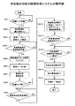
図5は、本実施の形態の画像形成装置及び画像形成システムの動作の一例を示すフローチャート、図6は、本実施の形態の画像形成装置及び画像形成システムにおける長尺紙の搬送動作の一例を示す説明図で、以下に、各図を参照して、本実施の形態の画像形成装置及び画像形成システムの動作について説明する。
<Operation Example of Image Forming Apparatus and Image Forming System of Present Embodiment>
FIG. 5 is a flowchart illustrating an example of the operation of the image forming apparatus and the image forming system according to the present embodiment. FIG. 6 illustrates an example of a long paper conveying operation in the image forming apparatus and the image forming system according to the present embodiment. The operation of the image forming apparatus and the image forming system of the present embodiment will be described below with reference to the drawings.
制御部100は、図5のステップSA1で、画像を形成する印刷ジョブを受信すると、図5のステップSA2で、搬送モータ20M、転写モータ18M及び定着モータ30Mを駆動すると共に、給紙装置130及び巻き取り装置140を駆動して、所定の搬送速度Vsで長尺紙Pの搬送を開始する。搬送速度Vsは、画像形成部11における長尺紙Pへのトナー像の転写、及び、定着部3における長尺紙Pへの画像の定着による画像形成動作での搬送速度Vfより低速に設定される。
When receiving a print job for forming an image in step SA1 in FIG. 5, the
また、制御部100は、図5のステップSA3で、定着ヒータ34に通電し、加圧回転体30を構成する定着ローラ31等の加熱を開始する。定着ヒータ34に通電されることで、定着ヒータ34で加熱ローラ35が加熱され、加熱ローラ35に掛けられた定着ベルト36が加熱されて、定着ベルト36が掛けられた定着ローラ31が加熱される。制御部100は、定着ヒータ34に通電する電圧値あるいは電流値を制御することで、定着部温度tを、待機温度Twから定着温度Thまで上昇させる。
Further, in step SA3 in FIG. 5, the
尚、印刷ジョブの無い画像の非形成時に定着部温度tを待機温度Twに保つため、定着ヒータ34を所定の待機電圧値あるいは待機電流値で駆動している場合は、印刷ジョブの開始後、定着ヒータ34に通電する電圧値あるいは電流値を、待機電圧値あるいは待機電流値から上昇させる動作を行うこととしても良い。
When the fixing
定着部温度tを定着温度Thに上昇させるウォームアップ動作で、長尺紙Pの搬送速度を画像形成時より低下させることで、定着部温度tが定着部3での画像の定着が可能になるまでに搬送される長尺紙Pの量を減らすことができる。一方、長尺紙Pを搬送することで、定着部温度tが上昇する過程で、長尺紙Pの同一箇所に熱が加わることが防止され、定着ローラ31から長尺紙Pに掛かる熱の影響を抑制することができる。
In the warm-up operation in which the fixing unit temperature t is increased to the fixing temperature Th, the conveyance speed of the long paper P is decreased from the time of image formation, so that the fixing unit temperature t can fix the image in the fixing
制御部100は、図5のステップSA4で、温度センサ39で検知した定着部温度tが所定の定着温度Thに到達したと判断すると、図5のステップSA5で、ウォームアップ時の搬送速度Vsを、画像形成時の搬送速度Vf(Vf>Vs)に切り替える。また、制御部100は、図5のステップSA6で、アクチュエータ37bを制御して、加圧ローラ32を定着ローラ31に圧接させて、長尺紙Pを定着ローラ31に圧接させる。
If the
そして、制御部100は、図5のステップSA7で、画像形成部11により長尺紙Pにトナー像を転写して画像を形成すると共に、定着部3による加熱及び加圧で画像を長尺紙Pに定着させる。
In step SA7 in FIG. 5, the
制御部100は、図5のステップSA8で、印刷ジョブが終了したと判断すると、図5のステップSA9で、印刷ジョブの終了前に形成された最終の画像Pcの後端Peが、図6に一点鎖線で示すように定着部3を通過して、定着動作が終了したか判断する。
When the
制御部100は、最終の画像Pcの後端Peが定着部3を通過したと判断すると、図5のステップSA10で、定着ローラ31等の冷却動作を開始する。制御部100は、定着ローラ31等の冷却動作として、定着ヒータ34の通電を停止する。あるいは、定着ヒータ34に通電される電圧値または電流値を所定の待機電圧値または待機電流値まで下げる。また、冷却ファン38を駆動する。更に、温度センサ39で検知した定着部温度tに基づき、長尺紙Pの搬送速度を制御する。
When the
図7は、定着部温度と搬送速度の関係を示す説明図である。ここで、図7のグラフでは、縦軸が温度(℃)、横軸が定着部3からの距離(m)である。本実施の形態では、画像Pcの後端Peが画像確認可能位置Ppに到達すると、定着ローラ31等の冷却動作を終了する。
FIG. 7 is an explanatory diagram showing the relationship between the fixing unit temperature and the conveyance speed. Here, in the graph of FIG. 7, the vertical axis represents temperature (° C.) and the horizontal axis represents distance (m) from the fixing
上述したように、画像確認可能位置Ppは、巻き取り装置140で巻き取られたロール紙P12の最外周に露出する所定の位置に設定される。本実施の形態では、巻き取り装置140の導入口140aが設けられた導入口位置Ps、あるいは、巻き取り装置140において最上流側に設けられた搬送ガイドローラ140bが、画像確認可能範囲Pvの開始位置となる。また、ロール紙P12の最外周に露出する所定の位置が、画像確認可能範囲Pvの終了位置となる。
As described above, the image checkable position Pp is set to a predetermined position exposed on the outermost periphery of the roll paper P12 wound up by the winding
このため、定着ローラ31等の冷却動作の開始後、画像Pcの後端Peが画像確認可能範囲Pvにある間に冷却動作を終了させることで、画像Pcの後端Peが画像確認可能位置Ppに到達した時点で、定着ローラ31等の冷却動作が終了できるようになる。
For this reason, after the cooling operation of the fixing
定着ローラ31等の冷却動作では、温度センサ39で検知された定着部温度tが高い場合と低い場合を比較すると、定着部温度tが高い場合の方が、定着ローラ31等を所定の温度にまで冷却するのに要する時間が長くなる。
In the cooling operation of the fixing
ここで、定着部3から画像確認可能範囲Pvまでの距離は、画像確認可能位置Ppの位置で最大となる。このように、定着部3から画像確認可能位置Ppまでの距離が決められているので、定着ローラ31等の冷却動作の開始後、画像Pcの後端Peが画像確認可能位置Ppに到達するより前に冷却動作を終了させるためには、定着部温度tが高い場合、定着部温度tが低い場合に比較して搬送速度を低下させる必要がある。
Here, the distance from the fixing
そこで、温度センサ39で検知された定着部温度tが、目標とする冷却温度tcに低下するまでに要する時間を予め計測、あるいはシミュレーション等に基づき算出し、画像Pcの後端Peが画像確認可能位置Ppに到達するより前に冷却温度tcとなる搬送速度vを算出して、制御データを生成する。なお、冷却温度tcは、待機温度Twであっても良い。
Therefore, the time required for the fixing unit temperature t detected by the
図7に示す例では、温度センサ39で検知される定着部温度tの閾値として、第1の閾値温度T1と、第1の閾値温度T1より高い第2の閾値温度T2が設定される。温度センサ39で検知された定着部温度tが第1の閾値温度T1未満であると、搬送速度vはV1に設定される。
In the example shown in FIG. 7, the first threshold temperature T 1 and the second threshold temperature T 2 higher than the first threshold temperature T 1 are set as threshold values of the fixing unit temperature t detected by the
本例では、温度センサ39で検知された定着部温度tが第1の閾値温度T1未満である場合、画像Pcの後端Peが導入口位置Psに到達した時点で、定着部温度tが冷却温度tc以下となるように搬送速度vが設定される。このような例では、画像Pcの後端Peが導入口位置Psに到達すると、冷却動作を終了することが可能である。
In this example, if the fixing unit temperature t detected by the
温度センサ39で検知された定着部温度tが第1の閾値温度T1以上第2の閾値温度T2未満であると、搬送速度vはV2に設定される。搬送速度V2は、搬送速度V1より低速に設定される。温度センサ39で検知された定着部温度tが第2の閾値温度T2以上であると、搬送速度vはV3に設定される。搬送速度V3は、搬送速度V2より低速に設定される。そして、画像Pcの後端Peが画像確認可能位置Ppに到達するより前に、定着部温度tが冷却温度tcにまで低下するように、各搬送速度vが設定される。
When the fixing unit temperature t detected by the
制御部100は、温度センサ39で検知された定着部温度tが第1の閾値温度T1未満であると、搬送速度V1で長尺紙Pを搬送する。温度センサ39で検知された定着部温度tが第1の閾値温度T1以上第2の閾値温度T2未満であると、搬送速度V2で長尺紙Pを搬送する。温度センサ39で検知された定着部温度tが第2の閾値温度T2以上であると、搬送速度V3で長尺紙Pを搬送する。
制御部100は、図5のステップSA11で、温度センサ39で検知された定着部温度tが冷却温度tc以下に低下したと判断すると、図5のステップSA12で、長尺紙Pに形成された画像Pcの後端Peが、図6に実線で示すように、画像確認可能位置Ppに到達したか判断する。
When the
制御部100は、長尺紙Pに形成された画像Pcの後端Peが、画像確認可能位置Ppに到達したと判断すると、図5のステップSA13で、冷却ファン38の駆動を停止して、定着ローラ31等の冷却動作を終了する。また、図5のステップSA14で、長尺紙Pの搬送を停止する。更に、制御部100は、図5のステップSA15で、アクチュエータ37bを駆動して、加圧ローラ32を定着ローラ31から離間させて、長尺紙Pの圧接を解除する。
When the
<本実施の形態の画像形成装置及び画像形成システムの作用効果例>
長尺紙Pに対する印刷ジョブが終了すると、定着部3で定着された最終の画像Pcの後端Peが画像確認可能位置Ppに到達するまで、長尺紙Pを搬送すると共に、画像Pcの後端Peが画像確認可能位置Ppに到達するより前に、定着ローラ31等の加圧回転体30の冷却動作を終了させる。
<Examples of Effects of Image Forming Apparatus and Image Forming System of Embodiment>
When the print job for the long paper P is completed, the long paper P is conveyed until the trailing edge Pe of the final image Pc fixed by the fixing
画像確認可能位置Ppは、定着部3を通過した長尺紙Pの通紙経路において、長尺紙Pの搬送方向に沿って定着部3から下流側に所定の距離離れた位置から、巻き取り装置140で長尺紙Pが巻き取られたロール紙P12の最外周に露出する位置までの間に設定される。これにより、印刷ジョブ終了後、長尺紙Pの搬送を停止したときには、長尺紙Pに形成された最終の画像Pcは視認可能な範囲に存在する。従って、長尺紙Pにおいて、所望の画像が形成された部位を探して取り出す作業が容易に行える。
The image checkable position Pp is taken up from a position away from the fixing
また、長尺紙Pを画像確認可能位置Ppまで搬送した時点で、定着ローラ31等の冷却動作を終了させることで、画像Pcの後端Peが画像確認可能位置Ppを通過する位置まで長尺紙を搬送する必要が無く、長尺紙Pの搬送を停止させても、長尺紙Pに熱による跡が付くこと、及び、長尺紙Pが熱により変形することを抑制することができる。
Further, when the long paper P is conveyed to the image checkable position Pp, the cooling operation of the fixing
ここで、画像確認可能位置Ppが画像形成装置1A内に設定されると、印刷ジョブが終了した後、画像の後端が画像形成装置1A内に残存した状態で長尺紙Pの搬送が停止されるので、画像が形成された部位の長尺紙を取り出す作業性が悪い。また、定着ローラ31等を冷却する十分な時間が得られず、長尺紙Pに熱による跡が付く可能性、あるいは、長尺紙Pが熱により変形する可能性がある。
Here, when the image checkable position Pp is set in the
一方、画像確認可能位置Ppが、ロール紙P12の最外周より更に内側に設定されると、視認可能なロール紙の最外周の面に画像が存在しないので、画像を探す作業性が悪い。 On the other hand, when the image checkable position Pp is set further inside than the outermost periphery of the roll paper P12, there is no image on the outermost peripheral surface of the roll paper that can be visually recognized, so that the workability of searching for an image is poor.
これに対し、画像確認可能位置Ppを、巻き取り装置140の導入口140aから、巻き取り装置140で長尺紙Pが巻き取られたロール紙P12の最外周に露出する位置まで間に設定することで、印刷ジョブ終了後、長尺紙Pの搬送を停止したときには、長尺紙Pに形成された最終の画像Pcの後端Peは、画像形成装置1Aの外部で、視認可能な範囲に存在する。これにより、長尺紙Pにおいて、所望の画像が形成された部位を探して取り出す作業が容易に行える。
On the other hand, the image checkable position Pp is set between the
また、画像確認可能位置Ppを、巻き取り装置140において最上流側に設けられた搬送ガイドローラ140bから、ロール紙P12の最外周に露出する位置まで間に設定することで、長尺紙Pに形成された最終の画像Pcの後端Peは、搬送ガイドローラ140bで支持された部位とロール紙P12の間で視認可能な範囲に存在する。これにより、長尺紙Pにおいて、所望の画像が形成された部位を探して取り出す作業が更に容易に行える。
In addition, the image checkable position Pp is set between the
更に、画像確認可能位置Ppを、ロール紙P12を円、ロール紙P12に巻き取られる長尺紙Pを接線と見なした場合において接点に相当する位置に設定することで、最終の画像Pcの後端Peが、視認可能なロール紙P12の最外周の面に存在する。これにより、長尺紙Pにおいて画像が形成された部位を探して取り出す作業が容易に行える。 Further, the image checkable position Pp is set to a position corresponding to a contact point when the roll paper P12 is regarded as a circle and the long paper P wound around the roll paper P12 is regarded as a tangent, so that the final image Pc The rear end Pe exists on the outermost peripheral surface of the roll paper P12 that is visible. Thereby, it is possible to easily find and take out the portion where the image is formed on the long paper P.
また、最終の画像Pcの後端Peが、ロール紙P12の最外周の面まで搬送されることで、長尺紙Pの搬送に伴う定着ローラ31等の冷却動作で、長尺紙Pが搬送される距離を長くとれるので、定着ローラ31等の冷却に要する時間を確保することができる。
Further, the trailing edge Pe of the final image Pc is conveyed to the outermost peripheral surface of the roll paper P12, so that the long paper P is conveyed by the cooling operation of the fixing
長尺紙Pに対する印刷ジョブが終了して、定着ローラ31等の冷却動作を開始すると、長尺紙Pの搬送速度を画像形成時と切り替えることで、定着ローラ31等の冷却に要する最適な時間を確保することができると共に、冷却動作の時間が必要以上に長くなることが抑制され、ユーザを待たせる時間を短縮することができる。
When the print job for the long paper P is finished and the cooling operation of the fixing
また、定着ローラ31等の定着部温度を検知し、定着部温度に基づいて長尺紙Pの搬送速度を切り換えることで、定着ローラ31等の冷却に要するより最適な時間を確保することができると共に、ユーザを待たせる時間を更に短縮することができる。
Further, by detecting the fixing unit temperature of the fixing
更に、定着部温度を検知し、定着部温度と画像確認可能位置Ppまでの距離に基づき、
画像確認可能位置Ppに画像の後端が到達した時点で、冷却動作が終了するように長尺紙Pの搬送速度を切り換えることで、定着ローラ31等のより確実な冷却が可能になると共に、定着ローラ31等の冷却に要するより最適な時間を確保し、ユーザを待たせる時間を更に短縮することができる。
Furthermore, the fixing unit temperature is detected, and based on the distance between the fixing unit temperature and the image checkable position Pp,
When the trailing edge of the image reaches the image checkable position Pp, the conveyance speed of the long paper P is switched so that the cooling operation is completed, thereby enabling more reliable cooling of the fixing
また、定着ローラ31等の冷却動作では、長尺紙Pを定着ローラ31に圧接させた状態とすることで、長尺紙Pに放熱を行い、長尺紙Pの搬送に伴う定着ローラ31等の冷却を促進することができる。
In the cooling operation of the fixing
更に、長尺紙Pの搬送以外の冷却手段として、定着ローラ31等に送風を行う冷却ファン38を備えることで、定着ローラ31等の冷却をより促進でき、冷却動作に要する時間を短縮することができる。
Furthermore, by providing a cooling
本発明は、長尺紙にトナー像を転写、定着させて画像を形成する画像形成装置、及び、画像形成装置に対して長尺紙の供給、回収を行う装置を備えた画像形成システムに適用される。 The present invention is applied to an image forming apparatus that forms an image by transferring and fixing a toner image on a long paper, and an image forming system including a device that supplies and collects long paper to the image forming apparatus. Is done.
1A・・・画像形成装置、2・・・用紙搬送部、3・・・定着部、100・・・制御部、110・・・画像形成システム、120・・・用紙供給装置、130・・・給紙装置、140・・・巻き取り装置
DESCRIPTION OF
Claims (10)
前記供給装置から供給されると共に前記巻き取り装置で巻き取られる長尺紙を搬送する搬送手段と、
前記搬送手段で搬送される長尺紙に画像を形成する画像形成手段と、
前記画像形成手段で画像が形成された長尺紙に画像を定着させる定着手段と、
長尺紙に形成された画像の確認が可能な画像確認可能位置が、長尺紙の搬送方向に対して前記定着手段の下流側に設定される画像確認可能範囲の開始位置から、前記巻き取り装置で長尺紙が巻き取られるロール紙の最外周に設定された画像確認可能範囲の終了位置までの間に設定され、
長尺紙に対する画像の形成動作が終了すると、前記定着手段の冷却動作を開始すると共に、前記定着手段で定着された最終の画像の後端が画像確認可能位置に到達するまで、前記搬送手段で長尺紙を搬送し、画像の後端が画像確認可能位置に到達するまでに、前記定着手段の冷却動作を終了する制御手段と
を備えたことを特徴とする画像形成装置。 An image forming apparatus connected to a supply device for supplying long paper and a take-up device for winding the long paper,
Conveying means for conveying the long paper that is supplied from the supply device and wound by the winding device;
An image forming means for forming an image on a long paper transported by the transport means;
Fixing means for fixing the image on the long paper on which the image is formed by the image forming means;
From the start position of the image checkable range set at the downstream side of the fixing unit, the image checkable position where the image formed on the long paper can be checked is confirmed with respect to the transport direction of the long paper. It is set between the end position of the image checkable range set on the outermost periphery of the roll paper on which the long paper is wound by the device,
When the image forming operation on the long paper is finished, the fixing unit starts cooling operation, and the conveying unit continues until the rear end of the final image fixed by the fixing unit reaches the image checkable position. An image forming apparatus comprising: a control unit that transports a long sheet of paper and ends the cooling operation of the fixing unit until the trailing edge of the image reaches an image checkable position.
ことを特徴とする請求項1に記載の画像形成装置。 The control means is configured to wind up the long paper by the winding device from the start position of the image checkable range where the image checkable position is set at the introduction port where the long paper is introduced into the winding device. The image forming apparatus according to claim 1, wherein the image forming apparatus is set up to an end position of an image checkable range set on the outermost periphery of the roll paper.
ことを特徴とする請求項1に記載の画像形成装置。 The image forming apparatus according to claim 1, wherein the control unit is configured to set an image checkable position to an outermost periphery of a roll paper on which a long sheet is wound by the winding device.
前記制御手段は、前記温度検知手段で検知される前記定着手段の温度が冷却温度以下となるまで前記定着手段の冷却動作を行う
ことを特徴とする請求項1〜請求項3の何れか1項に記載の画像形成装置。 A temperature detecting means for detecting the temperature of the fixing means;
4. The cooling device according to claim 1, wherein the control unit performs a cooling operation of the fixing unit until a temperature of the fixing unit detected by the temperature detection unit becomes equal to or lower than a cooling temperature. 5. The image forming apparatus described in 1.
ことを特徴とする請求項1〜請求項4の何れか1項に記載の画像形成装置。 5. The image according to claim 1, wherein when the image forming operation on the long paper is completed, the control unit switches the transport speed of the long paper to that at the time of image formation. Forming equipment.
ことを特徴とする請求項4に記載の画像形成装置。 When the image forming operation on the long paper is completed, the control unit switches the conveyance speed of the long paper from that at the time of image formation based on the temperature of the fixing unit detected by the temperature detection unit. The image forming apparatus according to claim 4.
ことを特徴とする請求項4に記載の画像形成装置。 When the image forming operation on the long paper is completed, the control unit determines the conveyance speed of the long paper based on the temperature of the fixing unit detected by the temperature detection unit and the distance to the image checkable position. The image forming apparatus according to claim 4, wherein the image forming apparatus is switched with time.
前記制御手段は、前記定着手段への通電を停止する、あるいは、通電する電圧値または電流値を下げる、前記冷却手段で送風を行う動作の何れか、あるいは組み合わせで、前記定着手段の冷却動作を行う
ことを特徴とする請求項1〜請求項7の何れか1項に記載の画像形成装置。 A cooling means for blowing air to the fixing means;
The control unit may stop the energization of the fixing unit, reduce the voltage value or the current value to be energized, or perform the cooling operation of the fixing unit by any one or combination of operations of blowing air by the cooling unit. The image forming apparatus according to claim 1, wherein the image forming apparatus is performed.
前記制御手段は、前記駆動機構で前記加圧ローラにより長尺紙を前記定着ローラに圧接させて、長尺紙を搬送しながら前記定着手段の冷却動作を行い、前記定着手段の冷却動作が終了すると、前記駆動機構で前記加圧ローラを前記定着ローラから離間させて、長尺紙を前記定着ローラから離間させる
ことを特徴とする請求項1〜請求項8の何れか1項に記載の画像形成装置。 The fixing unit includes a drive mechanism for separating and contacting a pair of fixing rollers and a pressure roller,
The control means causes the driving mechanism to press the long paper against the fixing roller by the pressure roller, and performs the cooling operation of the fixing means while conveying the long paper, and the cooling operation of the fixing means is completed. 9. The image according to claim 1, wherein the driving mechanism separates the pressure roller from the fixing roller and separates the long paper from the fixing roller. Forming equipment.
長尺紙を巻き取る巻き取り装置と、
前記供給装置及び前記巻き取り装置に接続される画像形成装置を備え、
前記画像形成装置は、
前記供給装置から供給されると共に前記巻き取り装置で巻き取られる長尺紙を搬送する搬送手段と、
前記搬送手段で搬送される長尺紙に画像を形成する画像形成手段と、
前記画像形成手段で画像が形成された長尺紙に画像を定着させる定着手段と、
長尺紙に形成された画像の確認が可能な画像確認可能位置が、長尺紙の搬送方向に対して前記定着手段の下流側に設定される画像確認可能範囲の開始位置から、前記巻き取り装置で長尺紙が巻き取られるロール紙の最外周に設定された画像確認可能範囲の終了位置までの間に設定され、
長尺紙に対する画像の形成動作が終了すると、前記定着手段の冷却動作を開始すると共に、前記定着手段で定着された最終の画像の後端が画像確認可能位置に到達するまで、前記搬送手段で長尺紙を搬送し、画像の後端が画像確認可能位置に到達するまでに、前記定着手段の冷却動作を終了する制御手段とを備えた
ことを特徴とする画像形成システム。 A supply device for supplying long paper;
A take-up device for taking up long paper;
An image forming apparatus connected to the supply device and the winding device;
The image forming apparatus includes:
Conveying means for conveying the long paper that is supplied from the supply device and wound by the winding device;
An image forming means for forming an image on a long paper transported by the transport means;
Fixing means for fixing the image on the long paper on which the image is formed by the image forming means;
From the start position of the image checkable range set at the downstream side of the fixing unit, the image checkable position where the image formed on the long paper can be checked is confirmed with respect to the transport direction of the long paper. It is set between the end position of the image checkable range set on the outermost periphery of the roll paper on which the long paper is wound by the device,
When the image forming operation on the long paper is finished, the fixing unit starts cooling operation, and the conveying unit continues until the rear end of the final image fixed by the fixing unit reaches the image checkable position. An image forming system comprising: a control unit that transports a long sheet of paper and ends the cooling operation of the fixing unit until the trailing edge of the image reaches an image checkable position.
Priority Applications (3)
| Application Number | Priority Date | Filing Date | Title |
|---|---|---|---|
| JP2015187866A JP6206460B2 (en) | 2015-09-25 | 2015-09-25 | Image forming apparatus and image forming system |
| US15/264,692 US9946201B2 (en) | 2015-09-25 | 2016-09-14 | Image-forming apparatus and image-forming system |
| CN201610848888.3A CN107037707B (en) | 2015-09-25 | 2016-09-23 | Image forming apparatus and image forming system |
Applications Claiming Priority (1)
| Application Number | Priority Date | Filing Date | Title |
|---|---|---|---|
| JP2015187866A JP6206460B2 (en) | 2015-09-25 | 2015-09-25 | Image forming apparatus and image forming system |
Publications (2)
| Publication Number | Publication Date |
|---|---|
| JP2017062363A JP2017062363A (en) | 2017-03-30 |
| JP6206460B2 true JP6206460B2 (en) | 2017-10-04 |
Family
ID=58409120
Family Applications (1)
| Application Number | Title | Priority Date | Filing Date |
|---|---|---|---|
| JP2015187866A Active JP6206460B2 (en) | 2015-09-25 | 2015-09-25 | Image forming apparatus and image forming system |
Country Status (3)
| Country | Link |
|---|---|
| US (1) | US9946201B2 (en) |
| JP (1) | JP6206460B2 (en) |
| CN (1) | CN107037707B (en) |
Families Citing this family (4)
| Publication number | Priority date | Publication date | Assignee | Title |
|---|---|---|---|---|
| JP2017198936A (en) * | 2016-04-28 | 2017-11-02 | コニカミノルタ株式会社 | Image formation system and cooling control method |
| JP2019008217A (en) | 2017-06-27 | 2019-01-17 | コニカミノルタ株式会社 | Image formation device, image formation system, image formation method, and image formation device-purpose program |
| JP6939420B2 (en) * | 2017-10-30 | 2021-09-22 | コニカミノルタ株式会社 | Image forming device and transfer control method |
| JP7114389B2 (en) * | 2018-07-31 | 2022-08-08 | キヤノン株式会社 | Fixing device |
Family Cites Families (12)
| Publication number | Priority date | Publication date | Assignee | Title |
|---|---|---|---|---|
| US5178063A (en) * | 1986-12-16 | 1993-01-12 | L & C Family Partnership | Method and apparatus for automatic numbering of forms on a rotary printing press |
| JP2708968B2 (en) * | 1991-02-28 | 1998-02-04 | シャープ株式会社 | Printing device |
| JP3629717B2 (en) * | 1994-03-16 | 2005-03-16 | 富士ゼロックス株式会社 | Printer apparatus and medium conveying method in the apparatus |
| JP3334704B2 (en) * | 2000-04-27 | 2002-10-15 | セイコーエプソン株式会社 | Printer |
| JP4048694B2 (en) * | 2000-05-31 | 2008-02-20 | コニカミノルタホールディングス株式会社 | Fixing device |
| JP3861660B2 (en) * | 2001-11-12 | 2006-12-20 | コニカミノルタビジネステクノロジーズ株式会社 | Continuous paper printer |
| US6934507B2 (en) * | 2002-12-24 | 2005-08-23 | Fuji Xerox Co., Ltd. | Image forming apparatus |
| JP4796528B2 (en) | 2007-03-23 | 2011-10-19 | 株式会社リコー | Paper transport control method and electrophotographic apparatus |
| JP5884799B2 (en) * | 2013-09-13 | 2016-03-15 | コニカミノルタ株式会社 | Image forming apparatus, image forming system, image forming method, and image forming program |
| JP6003921B2 (en) * | 2014-02-24 | 2016-10-05 | コニカミノルタ株式会社 | Image forming apparatus |
| JP6003922B2 (en) * | 2014-02-24 | 2016-10-05 | コニカミノルタ株式会社 | Image forming apparatus |
| JP6024692B2 (en) * | 2014-03-18 | 2016-11-16 | コニカミノルタ株式会社 | Image forming apparatus |
-
2015
- 2015-09-25 JP JP2015187866A patent/JP6206460B2/en active Active
-
2016
- 2016-09-14 US US15/264,692 patent/US9946201B2/en not_active Expired - Fee Related
- 2016-09-23 CN CN201610848888.3A patent/CN107037707B/en active Active
Also Published As
| Publication number | Publication date |
|---|---|
| US20170090362A1 (en) | 2017-03-30 |
| US9946201B2 (en) | 2018-04-17 |
| JP2017062363A (en) | 2017-03-30 |
| CN107037707A (en) | 2017-08-11 |
| CN107037707B (en) | 2020-03-20 |
Similar Documents
| Publication | Publication Date | Title |
|---|---|---|
| US8401412B2 (en) | Conveyance speed difference maintaining heat and pressure fixing system | |
| US8577273B2 (en) | Image forming apparatus having sheet cooling device | |
| JP6272134B2 (en) | Fixing device | |
| JP6206460B2 (en) | Image forming apparatus and image forming system | |
| JP6330722B2 (en) | Image forming apparatus and image forming system | |
| US9671739B2 (en) | Sheet-conveying device that conveys sheets, and image-forming apparatus using the same | |
| JP2012189672A (en) | Image forming device and image forming method | |
| JP2010014759A (en) | Image forming apparatus | |
| JP6187440B2 (en) | Image forming apparatus | |
| US9588467B2 (en) | Image forming apparatus | |
| JP2013238752A (en) | Image formation device | |
| US9897944B2 (en) | Image forming apparatus that corrects deviation of a belt member | |
| US10088783B2 (en) | Image forming apparatus and image forming system | |
| JP2019207318A (en) | Image forming apparatus and program | |
| JP6776557B2 (en) | Image forming device | |
| JP6372328B2 (en) | Image forming system, image forming apparatus, and control method of image forming apparatus | |
| JP5779960B2 (en) | Image forming apparatus and reverse conveying apparatus | |
| JP6528554B2 (en) | Image forming apparatus and image forming system | |
| JP2012083510A (en) | Fixing device and image forming apparatus | |
| JP2014056130A (en) | Image forming apparatus | |
| JP2011237743A (en) | Image-forming apparatus | |
| JP2011158809A (en) | Fixing device and image forming apparatus | |
| JP2019020498A (en) | Image formation device | |
| JP4468273B2 (en) | Sheet conveying apparatus and image forming apparatus | |
| JP2010014756A (en) | Image forming apparatus |
Legal Events
| Date | Code | Title | Description |
|---|---|---|---|
| A621 | Written request for application examination |
Free format text: JAPANESE INTERMEDIATE CODE: A621 Effective date: 20170123 |
|
| A977 | Report on retrieval |
Free format text: JAPANESE INTERMEDIATE CODE: A971007 Effective date: 20170731 |
|
| TRDD | Decision of grant or rejection written | ||
| A01 | Written decision to grant a patent or to grant a registration (utility model) |
Free format text: JAPANESE INTERMEDIATE CODE: A01 Effective date: 20170808 |
|
| A61 | First payment of annual fees (during grant procedure) |
Free format text: JAPANESE INTERMEDIATE CODE: A61 Effective date: 20170821 |
|
| R150 | Certificate of patent or registration of utility model |
Ref document number: 6206460 Country of ref document: JP Free format text: JAPANESE INTERMEDIATE CODE: R150 |