JP6201674B2 - Storage control device, program, and control method - Google Patents
Storage control device, program, and control method Download PDFInfo
- Publication number
- JP6201674B2 JP6201674B2 JP2013239897A JP2013239897A JP6201674B2 JP 6201674 B2 JP6201674 B2 JP 6201674B2 JP 2013239897 A JP2013239897 A JP 2013239897A JP 2013239897 A JP2013239897 A JP 2013239897A JP 6201674 B2 JP6201674 B2 JP 6201674B2
- Authority
- JP
- Japan
- Prior art keywords
- storage device
- spare storage
- spare
- replacement
- replaced
- Prior art date
- Legal status (The legal status is an assumption and is not a legal conclusion. Google has not performed a legal analysis and makes no representation as to the accuracy of the status listed.)
- Active
Links
Images


Classifications
-
- G—PHYSICS
- G06—COMPUTING; CALCULATING OR COUNTING
- G06F—ELECTRIC DIGITAL DATA PROCESSING
- G06F11/00—Error detection; Error correction; Monitoring
- G06F11/07—Responding to the occurrence of a fault, e.g. fault tolerance
- G06F11/08—Error detection or correction by redundancy in data representation, e.g. by using checking codes
- G06F11/10—Adding special bits or symbols to the coded information, e.g. parity check, casting out 9's or 11's
- G06F11/1076—Parity data used in redundant arrays of independent storages, e.g. in RAID systems
- G06F11/1092—Rebuilding, e.g. when physically replacing a failing disk
-
- G—PHYSICS
- G06—COMPUTING; CALCULATING OR COUNTING
- G06F—ELECTRIC DIGITAL DATA PROCESSING
- G06F11/00—Error detection; Error correction; Monitoring
- G06F11/07—Responding to the occurrence of a fault, e.g. fault tolerance
- G06F11/16—Error detection or correction of the data by redundancy in hardware
- G06F11/20—Error detection or correction of the data by redundancy in hardware using active fault-masking, e.g. by switching out faulty elements or by switching in spare elements
- G06F11/202—Error detection or correction of the data by redundancy in hardware using active fault-masking, e.g. by switching out faulty elements or by switching in spare elements where processing functionality is redundant
- G06F11/2041—Error detection or correction of the data by redundancy in hardware using active fault-masking, e.g. by switching out faulty elements or by switching in spare elements where processing functionality is redundant with more than one idle spare processing component
-
- G—PHYSICS
- G06—COMPUTING; CALCULATING OR COUNTING
- G06F—ELECTRIC DIGITAL DATA PROCESSING
- G06F11/00—Error detection; Error correction; Monitoring
- G06F11/07—Responding to the occurrence of a fault, e.g. fault tolerance
- G06F11/16—Error detection or correction of the data by redundancy in hardware
- G06F11/20—Error detection or correction of the data by redundancy in hardware using active fault-masking, e.g. by switching out faulty elements or by switching in spare elements
- G06F11/2053—Error detection or correction of the data by redundancy in hardware using active fault-masking, e.g. by switching out faulty elements or by switching in spare elements where persistent mass storage functionality or persistent mass storage control functionality is redundant
- G06F11/2094—Redundant storage or storage space
-
- G—PHYSICS
- G06—COMPUTING; CALCULATING OR COUNTING
- G06F—ELECTRIC DIGITAL DATA PROCESSING
- G06F3/00—Input arrangements for transferring data to be processed into a form capable of being handled by the computer; Output arrangements for transferring data from processing unit to output unit, e.g. interface arrangements
- G06F3/06—Digital input from, or digital output to, record carriers, e.g. RAID, emulated record carriers or networked record carriers
- G06F3/0601—Interfaces specially adapted for storage systems
- G06F3/0602—Interfaces specially adapted for storage systems specifically adapted to achieve a particular effect
- G06F3/0604—Improving or facilitating administration, e.g. storage management
- G06F3/0607—Improving or facilitating administration, e.g. storage management by facilitating the process of upgrading existing storage systems, e.g. for improving compatibility between host and storage device
-
- G—PHYSICS
- G06—COMPUTING; CALCULATING OR COUNTING
- G06F—ELECTRIC DIGITAL DATA PROCESSING
- G06F3/00—Input arrangements for transferring data to be processed into a form capable of being handled by the computer; Output arrangements for transferring data from processing unit to output unit, e.g. interface arrangements
- G06F3/06—Digital input from, or digital output to, record carriers, e.g. RAID, emulated record carriers or networked record carriers
- G06F3/0601—Interfaces specially adapted for storage systems
- G06F3/0602—Interfaces specially adapted for storage systems specifically adapted to achieve a particular effect
- G06F3/061—Improving I/O performance
- G06F3/0613—Improving I/O performance in relation to throughput
-
- G—PHYSICS
- G06—COMPUTING; CALCULATING OR COUNTING
- G06F—ELECTRIC DIGITAL DATA PROCESSING
- G06F3/00—Input arrangements for transferring data to be processed into a form capable of being handled by the computer; Output arrangements for transferring data from processing unit to output unit, e.g. interface arrangements
- G06F3/06—Digital input from, or digital output to, record carriers, e.g. RAID, emulated record carriers or networked record carriers
- G06F3/0601—Interfaces specially adapted for storage systems
- G06F3/0628—Interfaces specially adapted for storage systems making use of a particular technique
- G06F3/0629—Configuration or reconfiguration of storage systems
- G06F3/0631—Configuration or reconfiguration of storage systems by allocating resources to storage systems
-
- G—PHYSICS
- G06—COMPUTING; CALCULATING OR COUNTING
- G06F—ELECTRIC DIGITAL DATA PROCESSING
- G06F3/00—Input arrangements for transferring data to be processed into a form capable of being handled by the computer; Output arrangements for transferring data from processing unit to output unit, e.g. interface arrangements
- G06F3/06—Digital input from, or digital output to, record carriers, e.g. RAID, emulated record carriers or networked record carriers
- G06F3/0601—Interfaces specially adapted for storage systems
- G06F3/0628—Interfaces specially adapted for storage systems making use of a particular technique
- G06F3/0629—Configuration or reconfiguration of storage systems
- G06F3/0635—Configuration or reconfiguration of storage systems by changing the path, e.g. traffic rerouting, path reconfiguration
-
- G—PHYSICS
- G06—COMPUTING; CALCULATING OR COUNTING
- G06F—ELECTRIC DIGITAL DATA PROCESSING
- G06F3/00—Input arrangements for transferring data to be processed into a form capable of being handled by the computer; Output arrangements for transferring data from processing unit to output unit, e.g. interface arrangements
- G06F3/06—Digital input from, or digital output to, record carriers, e.g. RAID, emulated record carriers or networked record carriers
- G06F3/0601—Interfaces specially adapted for storage systems
- G06F3/0668—Interfaces specially adapted for storage systems adopting a particular infrastructure
- G06F3/0671—In-line storage system
- G06F3/0683—Plurality of storage devices
Landscapes
- Engineering & Computer Science (AREA)
- Theoretical Computer Science (AREA)
- Physics & Mathematics (AREA)
- General Engineering & Computer Science (AREA)
- General Physics & Mathematics (AREA)
- Human Computer Interaction (AREA)
- Quality & Reliability (AREA)
- Computer Networks & Wireless Communication (AREA)
- Information Retrieval, Db Structures And Fs Structures Therefor (AREA)
- Debugging And Monitoring (AREA)
Description
本発明は、ストレージ制御装置,プログラム及び制御方法に関する。 The present invention relates to a storage control device, a program, and a control method.
ストレージ装置において記憶装置が故障し、又は、記憶装置の予防交換を行なう場合には、Hot Spare(HS;予備記憶装置)にデータコピー(リビルド/冗長コピー)を行なう。そして、リビルド(再構築)/リダンダントコピー(冗長コピー)が完了し、故障した記憶装置又は予防交換対象の記憶装置の交換を行なった後に、HSから交換後の記憶装置に対してコピーバックを行なう。 When the storage device fails in the storage device or when the preventive replacement of the storage device is performed, data copy (rebuild / redundant copy) is performed to Hot Spare (HS; spare storage device). Then, after rebuilding (rebuilding) / redundant copying (redundant copying) is completed and the failed storage device or the storage device subject to preventive replacement is replaced, the HS performs copy back to the replaced storage device. .
従来のストレージ装置の動作は、ホスト専用であり、殆ど構成変更を行なわない前提があり、コピーバック動作についても周知の事実・保守手順の一環となっている。 The operation of the conventional storage apparatus is for the host only, and it is assumed that the configuration is hardly changed. The copy back operation is also part of a well-known fact / maintenance procedure.
しかしながら、HSからコピーバックを行なう際には、例えば、コピーバックが完了するまでストレージ装置の監視を行なわなければならず、又、コピーバック中はInput/Output(I/O)性能に影響が生じる。すなわち、ストレージ装置が備えられるシステムのオープンシステム化や共同利用化(クラウド化等)が進行し、運用形態にあった運用作業(コピーバック動作)による負荷の軽減が課題である。 However, when copying back from the HS, for example, the storage apparatus must be monitored until the copy back is completed, and input / output (I / O) performance is affected during the copy back. . That is, open systems and shared use (such as cloud computing) of systems equipped with storage devices have progressed, and there is a problem of reducing the load due to operation work (copy back operation) suited to the operation mode.
1つの側面では、本発明は、記憶装置の入れ替えを効率的に行なうことを目的とする。
なお、前記目的に限らず、後述する発明を実施するための形態に示す各構成により導かれる作用効果であって、従来の技術によっては得られない作用効果を奏することも本発明の他の目的の1つとして位置付けることができる。
In one aspect, an object of the present invention is to efficiently replace storage devices.
In addition, the present invention is not limited to the above-described object, and other effects of the present invention can be achieved by the functions and effects derived from the respective configurations shown in the embodiments for carrying out the invention which will be described later. It can be positioned as one of
このため、このストレージ制御装置は、複数の記憶装置及び複数の予備記憶装置と複数の経路を介して通信可能に接続されたストレージ制御装置であって、前記複数の予備記憶装置と前記複数の経路とを対応付けた経路情報を記憶するメモリと、前記複数の記憶装置のうち入れ替え対象の記憶装置が接続されている経路により定まる経路接続条件と前記経路情報とに基づいて、前記複数の予備記憶装置の中から入れ替え先の予備記憶装置を選択する選択部と、前記選択された入れ替え先の予備記憶装置に前記入れ替え対象の記憶装置が格納するデータを書き込む書き込み処理部と、前記経路接続条件を満さない第1の予備記憶装置が前記入れ替え先の予備記憶装置として選択された場合に、新たに利用可能となった第2の予備記憶装置を検知する検知部と、を備え、前記第2の予備記憶装置が前記経路接続条件を満たす場合に、前記選択部は、前記入れ替え先の予備記憶装置として前記第2の予備記憶装置を選択し、前記書き込み処理部は、前記第1の予備記憶装置に対するデータの書き込みを継続するとともに、前記第1の予備記憶装置へのデータの書き込みが完了していない領域から前記第2の予備記憶装置に対してデータを書き込み、前記第1の予備記憶装置に書き込んだデータを前記第2の予備記憶装置にコピーする。 Therefore, the storage control device is a storage control device that is communicably connected to a plurality of storage devices and a plurality of spare storage devices via a plurality of routes, and the plurality of spare storage devices and the plurality of routes Based on the path connection condition determined by the path to which the storage device to be exchanged is connected and the path information, and the path information. A selection unit for selecting a spare storage device to be replaced from among the devices, a write processing unit for writing data stored in the storage device to be replaced into the selected spare storage device for replacement, and the path connection condition. When a first spare storage device that is not satisfied is selected as the replacement spare storage device, a second spare storage device that is newly available is detected. And when the second spare storage device satisfies the path connection condition, the selection unit selects the second spare storage device as the replacement spare storage device, and The write processing unit continues to write data to the first spare storage device and starts writing data to the first spare storage device from an area where writing of data to the first spare storage device is not completed. Data is written, and the data written in the first spare storage device is copied to the second spare storage device .
開示のストレージ制御装置によれば、記憶装置の入れ替えを効率的に行なうことができる。 According to the disclosed storage control device, it is possible to efficiently replace storage devices.
以下、図面を参照してストレージ制御装置,プログラム及び制御方法に係る一実施の形態を説明する。ただし、以下に示す実施形態はあくまでも例示に過ぎず、実施形態で明示しない種々の変形例や技術の適用を排除する意図はない。すなわち、本実施形態を、その趣旨を逸脱しない範囲で種々変形して実施することができる。
また、各図は、図中に示す構成要素のみを備えるという趣旨ではなく、他の機能等を含むことができる。
Hereinafter, an embodiment according to a storage control device, a program, and a control method will be described with reference to the drawings. However, the embodiment described below is merely an example, and there is no intention to exclude application of various modifications and techniques not explicitly described in the embodiment. That is, the present embodiment can be implemented with various modifications without departing from the spirit of the present embodiment.
Each figure is not intended to include only the components shown in the figure, and may include other functions.
以下、図中において、同一の各符号は同様の部分を示しているので、その説明は省略する。
〔A〕実施形態の一例
〔A−1〕システム構成
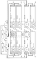
図1は、実施形態の一例としてのストレージシステムの機能構成を模式的に示す図である。
Hereinafter, in the drawings, the same reference numerals indicate the same parts, and the description thereof is omitted.
[A] Example of Embodiment [A-1] System Configuration FIG. 1 is a diagram schematically illustrating a functional configuration of a storage system as an example of an embodiment.
本実施形態の一例におけるストレージシステム100は、図1に示すように、ストレージ装置(ストレージディスクアレイ装置)1及びサーバ2を備える。これらのストレージ装置1とサーバ2とは、図示するように、例えばLocal Area Network(LAN)ケーブルを介して通信可能に接続されている。
サーバ2は、例えば、サーバ機能を備えたコンピュータ(情報処理装置)である。図1に示す例では、1つのサーバ2を備えているが、2つ以上のサーバ2を備えることとしても良い。
A
The
ストレージ装置1は、後述する複数の記憶装置21を搭載し、サーバ2に対して記憶領域を提供する装置であり、Redundant Arrays of Inexpensive Disks(RAID)を用いて複数の記憶装置21にデータを分散し、冗長化した状態で保存する。ストレージ装置1は、2つのControl Module#0,#1(CM#0,#1;ストレージ制御装置)10及び複数のDisk Enclosure(DE)20を備える。
The
以下、特定のCMを指す場合は、単に「CM#0」又は「CM#1」と表記するが、任意のCMを指す場合は、「CM10」と表記する。
図1に示すように、CM#0とCM#1とは例えばPeripheral Component Interconnect Express(PCIe)バスを介して通信可能に接続されており、CM10とDE20とは例えばバス線(アクセスパス)を介して通信可能に接続されている。
Hereinafter, when referring to a specific CM, it is simply expressed as “
As shown in FIG. 1,
DE20は、冗長化のためにCM#0,#1のぞれぞれとアクセスパスで通信可能に接続されており、それぞれ複数の記憶装置21を備える。
記憶装置21は、データを読み書き可能に格納する既知の装置であり、例えば、Hard Disk Drive(HDD)やSolid State Drive(SSD)である。これらの記憶装置21は、互いに同様の機能構成を備える。各DE20が備える複数の記憶装置21のうち、少なくとも1つは図2に示すようにHS21aとして機能する。
The
The
CM10は、種々の制御を行なう制御装置であり、サーバ2からのストレージアクセス要求(アクセス制御信号:以下、ホストI/Oという)に従って、各種制御を行なう。CM10は、Central Processing Unit(CPU)11,メモリ12,複数のポート13及びCommunication Adapter(CA)14を備える。なお、図1に示す例においては、ストレージ装置1が2つのCM10を備えることとしたが、これに限定されるものではなく、1つ又は3つ以上のCM10を備えることとしても良い。
The
CA14は、サーバ2と通信可能に接続するインタフェースコントローラである。
ポート13は、CM10とDE20とを通信可能に接続するためのインタフェースとしてのDevice Adapter(DA)であり、例えばFiber Channel(FC)アダプタである。C
M10は、このポート13を介してDE20に対するデータの書き込みや読み出しを行なう。
The
The
M10 performs writing and reading data to DE20 via the
メモリ12は、Read Only Memory(ROM)及びRandom Access Memory(RAM)を含む記憶装置である。メモリ12のROMには、Basic Input/Output System(BIOS)等のプログラムが書き込まれている。メモリ12上のソフトウェアプログラムは、CPU11に適宜読み込まれて実行される。また、メモリ12のRAMは、一次記録メモリあるいはワーキングメモリとして利用される。本実施形態の一例において、メモリ12は、経路接続条件(図2を用いて後述)に関する情報,経路情報(図3を用いて後述),RAID構成情報(図3を用いて後述)及び記憶装置性能情報(図3を用いて後述)を格納する。なお、経路接続条件に関する情報,経路情報,RAID構成情報及び記憶装置性能情報は、CM10が備える図示しない記憶装置が格納しても良い。
The
CPU11は、種々の制御や演算を行なう処理装置であり、メモリ12に格納されたOperating System(OS)やプログラムを実行することにより、種々の機能を実現する。すなわち、CPU11は、図1に示すように、検知部111,選択部112,書き込み処理部113及び入れ替え処理部114として機能する。
なお、これらの検知部111,選択部112,書き込み処理部113及び入れ替え処理部114としての機能を実現するためのプログラムは、例えばフレキシブルディスク,CD(CD−ROM,CD−R,CD−RW等),DVD(DVD−ROM,DVD−RAM,DVD−R,DVD+R,DVD−RW,DVD+RW,HD DVD等),ブルーレイディスク,磁気ディスク,光ディスク,光磁気ディスク等の、コンピュータ読取可能な記録媒体に記録された形態で提供される。そして、コンピュータはその記録媒体から図示しない読取装置を介してプログラムを読み取って内部記録装置または外部記録装置に転送し格納して用いる。又、そのプログラムを、例えば磁気ディスク,光ディスク,光磁気ディスク等の記憶装置(記録媒体)に記録しておき、その記憶装置から通信経路を介してコンピュータに提供してもよい。
The
The program for realizing the functions as the
検知部111,選択部112,書き込み処理部113及び入れ替え処理部114としての機能を実現する際には、内部記憶装置(本実施形態ではメモリ12)に格納されたプログラムがコンピュータのマイクロプロセッサ(本実施形態ではCPU11)によって実行される。このとき、記録媒体に記録されたプログラムをコンピュータが読み取って実行してもよい。
When realizing the functions as the
なお、本ストレージ装置1は、CM#0をプライマリとし、CM#1をセカンダリとすることによって、冗長化されていても良い。また、プライマリであるCM#0が故障した場合には、セカンダリであるCM#1は、CM#0の機能を引き継ぐようにしても良い。
検知部111は、入れ替え対象の記憶装置21を特定する。具体的には、検知部111は、記憶装置21の故障等の異常発生を検知し、又、記憶装置21に対するオペレータからの予防交換の要求の発生を検知することで、入れ替え対象の記憶装置21を特定する。なお、記憶装置21の予防交換を行なう場合には、検知部111は、記憶装置21がストレージ装置1に組み込まれてから一定時間が経過したことを検知しても良いし、特定の記憶装置21に対するホストI/Oによって所定回数以上エラーが発生したことを検知しても良い。また、検知部111は、図7を用いて後述するように、非適合HSに対する書き込み処理実行中に利用可能となった適合HSを検知する。
The
The
選択部112は、ストレージ装置1が備える複数のHS21aのうち、入れ替え先のHS21aを選択する。具体的には、選択部112は、検知部111が入れ替え対象の記憶装置21を特定した場合に、入れ替え対象の記憶装置21が格納するデータを書き込む入れ替え先のHS21aを選択する。選択部112による入れ替え先のHS21aの具体的な選択手法は、図2を用いて後述する。
The
書き込み処理部113は、記憶装置21にデータを書き込む。具体的には、書き込み処理部113は、選択部112が選択した入れ替え先のHS21aに対してリビルド/冗長コピー(データディスク構築)の処理を実行する。同一のRAIDグループを構成する複数の記憶装置21は、各記憶装置21のデータが他の複数の記憶装置21に分散してコピーされることにより、冗長化されている。書き込み処理部113は、入れ替え対象の記憶装置21とRAIDグループを構成する複数の記憶装置21にそれぞれ格納されたデータを読み出して、入れ替え先のHS21aに格納することで、入れ替え対象の記憶装置21のデータを復元(データディスク構築)する。また、書き込み処理部113は、入れ替え対象の記憶装置21の交換後に、入れ替え先のHS21aに書き込まれたデータを交換後の記憶装置21にコピーバックする(書き戻す)書き戻し処理部113aとしても機能する。書き込み処理部113による具体的な書き込み手法は図4及び図6を用いて後述し、書き戻し処理部113aによる具体的な書き戻し手法は図6を用いて後述する。
The
入れ替え処理部114は、書き込み処理部113によるリビルド/冗長コピー完了後、入れ替え対象の記憶装置21と入れ替え先のHS21aとの定義(図5を用いて後述する記憶装置構成情報)が入れ替え可能であるかを判断する。また、入れ替え処理部114は、書き込み処理部113によりデータが書き込まれたHS21aを用いて入れ替え対象の記憶装置21を置換する。入れ替え処理部114による具体的な入れ替え手法は、図4を用いて後述する。
After the rebuild / redundant copy is completed by the
以下、図2〜図7を用いて、検知部111,選択部112,書き込み処理部113及び入れ替え処理部114としての機能を詳述する。
図2は、実施形態の一例としてのストレージ装置における選択部によるHS選択処理を例示する図である。
図2に示す例において、CM10は、4つの経路#0〜#3を介して、8つのDE20と通信可能に接続されている。この図2に示す例では、8つのDE20に対して、#00,#01,#10,#11,#20,#21,#30及び#31をそれぞれ付して示している。
Hereinafter, functions as the
FIG. 2 is a diagram illustrating an HS selection process by the selection unit in the storage apparatus as an example of the embodiment.
In the example illustrated in FIG. 2, the
以下、特定のDEを指す場合は、「DE#00」,「DE#01」,「DE#10」,「DE#11」,「DE#20」,「DE#21」,「DE#30」または「DE#31」と表記するが、任意のDEを指す場合は、「DE20」と表記する。また、以下、CM10と経路#0〜#3を介してそれぞれ直接接続されているDE#00,#10,#20,#30を基本DE20という場合がある。更に、以下、CM10とDE#00,#10,#20,#30を介してそれぞれ間接接続(カスケード接続)されているDE#01,#11,#21,#31を拡張DE20という場合がある。
Hereinafter, when referring to a specific DE, “
CM10は、#0〜#3で示す4つのポート13を備える。以下、特定のポートを指す場合は、「ポート#0」〜「ポート#3」と表記するが、任意のポートを指す場合は、「ポート13」と表記する。ポート#0〜#3は、経路#0〜#3とそれぞれ接続されている。
DE20は、1つのHS21aを含む複数の記憶装置21及びエキスパンダ22を備える。なお、図2に示す例においては、簡単のため一部の記憶装置21の図示を省略している。
The
The
エキスパンダ22は、CM10とDE20とを中継する装置であり、ホストI/Oに基づくデータ転送を行なう。すなわち、CM10は、各DE20に対して、エキスパンダ22を介してアクセスする。図2に示す例において、基本DE20のエキスパンダ22はCM10及び拡張DE20と接続されており、拡張DE20のエキスパンダ22は基本DE20と接続されている。そして、このエキスパンダ22を介して、複数のDE20がカスケード接続(多段接続)される。
The
検知部111は、例えば故障がDE#10の記憶装置21で発生したことを検知し、又は、予防交換の要求がDE#10の記憶装置21に対して発生したことを検知する(符号A1参照)。言い換えれば、検知部111は、符号A1で示した記憶装置を入れ替え対象の記憶装置21として特定する。
図2に示す例において、入れ替え対象の記憶装置21とDE#00の記憶装置21とは、RAIDグループを構成している。
The
In the example shown in FIG. 2, the
選択部112は、ストレージ装置1が備える複数のHS21aのうち、入れ替え対象の記憶装置21との入れ替えに用いる入れ替え先のHS21aを選択する。
具体的には、選択部112は、入れ替え対象の記憶装置が接続されている経路と、取得した経路により定まる経路接続条件とをメモリ12から取得する。また、選択部112は、ストレージ装置1が備える複数のHS21aの経路を示す経路情報(図3を用いて後述)やRAID構成を示すRAID構成情報(図3を用いて後述)をメモリ12から取得する。
The
Specifically, the
そして、選択部112は、ストレージ装置1のRAID構成において、経路接続の観点でより冗長性が高いHS21aを入れ替え先のHS21aとして選択する。
選択部112は、複数のHS21aのうち、入れ替え対象の記憶装置21が接続されている経路と同一経路上のHS21aを入れ替え先のHS21aの第1候補として選択する。ここで、同一経路とは、同一のポート13に接続されていることを示す。つまり、図2に示す例においては、選択部112は、入れ替え対象の記憶装置21に対して、経路#1を介してCM10と接続されているDE#10,#11のHS21aを第1候補のHS21aとして選択する(符号A2参照)。なお、第1候補のHS21aが複数ある場合には(例えばDE#10,#11のHS21a)、選択部112は、カスケード接続の段数が少なくCM10に近い基本DE20(例えばDE#10)のHS21aを優先して第1候補として選択する。
Then, the
The
また、選択部112は、複数のHS21aのうち、入れ替え対象の記憶装置21が接続されていない経路上にあり、且つ、入れ替え対象の記憶装置21とRAIDグループを構成していない経路上にあるHS21aを入れ替え先のHS21aの第2候補として選択する。つまり、選択部112は、経路#2,#3を介してCM10と接続されているDE#20,#21,#30,#31のHS21aを第2候補のHS21aとして選択する(符号A3参照)。なお、第2候補のHS21aが複数ある場合には(例えばDE#20,#21,#30,#31のHS21a)、選択部112は、経路番号の値が小さいDE20(例えばDE#20,#21)のHS21aを優先して第2候補として選択する。また、経路番号が最小の経路上のDE20(例えばDE#20,#21)が複数ある場合には、選択部112は、カスケード接続の段数が少なくCM10に近い基本DE20(例えばDE#20)のHS21aを優先して第2候補として選択する。
In addition, the
すなわち、選択部112は、入れ替え対象の記憶装置21が接続されている経路に基づいて、複数のHS21aのうち、経路接続条件を満たすHS21aを入れ替え先のHS21aとして選択する。経路接続条件とは、例えば、入れ替え対象の記憶装置21が接続されている経路により定まる条件である。そして、選択部112は、経路接続条件を用いることにより、第1候補又は第2候補のHS21aを入れ替え先のHS21aとして選択する。
That is, the
更に、選択部112は、入れ替え先のHS21aとして、複数のHS21aのうち、入れ替え対象の記憶装置21を基準とする性能条件を満たすHS21aを優先して選択する。つまり、選択部112は、第1候補のHS21aが性能条件を満たすかを判定する。そして、第1候補のHS21aが性能条件を満たす場合には、選択部112は、第1候補のHS21aを選択する。一方、第1候補のHS21aが性能条件を満たさない場合には、選択部112は、第2候補のHS21aが性能条件を満たすかを判定する。そして、第2候補のHS21aが性能条件を満たす場合には、選択部112は、第2候補のHS21aを選択する。一方、第2候補のHS21aが性能条件を満たさない場合には、選択部112は、経路番号の値が小さいDE20のHS21aを優先して選択する。また、経路番号が最小の経路上のDE20(例えばDE#00,#01)が複数ある場合には、選択部112は、カスケード接続の段数が少なくCM10に近い基本DE20(例えばDE#00)を優先して選択する。
Furthermore, the
図3は、実施形態の一例としてのストレージ装置における記憶装置性能情報を例示する図である。
記憶装置性能情報には、各記憶装置21について、例えば、Physical Logical Unit(PLU)番号,DE番号,DE内Slot番号,HSとデータ記憶装置との別(HS or Data),iops,アクセス速度(MB/s),回転数,容量,ディスクサイズ(inch),HDDとSSDとの別(HDD or SSD),DE経路及びRAID Logical Unit(RLU)番号が対応づけられている。記憶装置性能情報は、例えばメモリ12が格納する。
FIG. 3 is a diagram illustrating storage device performance information in a storage device as an example of an embodiment.
In the storage device performance information, for each
PLU番号は、例えば、エキスパンダポート番号,DEカスケード番号及びDE内Slot番号を含み、16ビットの情報である。例えば、bit 1〜bit 4にはDE内Slot番号が登録され、bit 8〜bit 11にはDEカスケード番号が登録され、又、bit 12〜bit 13にはエキスパンダポート番号が登録されている。エキスパンダポート番号には記憶装置21(DE20)が接続されている経路に関する情報が登録されており、例えば図2に示した経路#0〜#3に対応する情報が登録されている。DEカスケード番号には、DE20の接続順序が登録されている。
The PLU number is, for example, 16-bit information including an expander port number, a DE cascade number, and a slot number in the DE. For example, a slot number in DE is registered in
DE経路は、エキスパンダポート番号に基づいて作成された情報であり、例えば図2に示した経路#0〜#3に対応する情報が登録されている。
RLU番号は、記憶装置21が属するRAIDグループの番号を示す情報である。記憶装置21がいずれかのRAIDグループに属している場合には、RLU番号には、該当するRAIDグループの番号が登録される。一方、記憶装置21(HS21a)が未使用の場合には、RLU番号には、RAIDグループの番号として使用されることのない番号(0xFFFF等)が登録されている。
The DE route is information created based on the expander port number. For example, information corresponding to
The RLU number is information indicating the number of the RAID group to which the
本実施形態の一例においては、記憶装置性能情報に含まれるDE経路及びRLU番号が経路情報及びRAID構成情報としてそれぞれ定義される。
そして、選択部112は、複数の記憶装置21のうち入れ替え対象の記憶装置21が接続されている経路により定まる経路接続条件と経路情報とに基づいて、複数のHS21aの中から入れ替え先のHS21aを選択する。具体的には、選択部112は、経路接続条件と経路情報とに基づき、複数のHS21aのうち、入れ替え対象の記憶装置21が接続されている経路と同一経路上のHS21aを入れ替え先のHS21aの第1候補として選択する。また、選択部112は、経路接続条件と経路情報とに基づき、複数のHS21aのうち、入れ替え対象の記憶装置21が接続されていない経路上にあり、且つ、入れ替え対象の記憶装置21とRAIDグループを構成していない経路上にあるHS21aを入れ替え先のHS21aの第2候補として選択する。
In an example of this embodiment, the DE path and RLU number included in the storage device performance information are defined as path information and RAID configuration information, respectively.
Then, the
選択部112は、例えばCM10が備えるメモリ12が格納する記憶装置性能情報に基づいて性能条件を判定する。
選択部112は、例えば、入れ替え先のHS21aの記憶装置性能情報のうち少なくとも一部の指標が入れ替え対象の記憶装置21の対応する指標と比較して同等以上であるか否かを判定することで、性能条件を満たすか否かを判定する。なお、記憶装置性能情報のうち性能条件の判定に用いる一部の指標は、種々選択することができる。また、記憶装置性能情報の指標(性能値)が同等以上であるかの判断は、性能値が閾値以上であるかの判断に基づいて行なう。閾値は、入れ替え対象の記憶装置21の性能値に基づいて設定される。そして、閾値には、入れ替え対象の記憶装置21の性能値に望ましい柔軟性を持たせるために、所定量(例えば5%)のマージンを持たせても良い。
For example, the
For example, the
以下、第1候補又は第2候補から選択され、且つ、性能条件を満たすHS21aを適合HSという。また、以下、第1候補及び第2候補以外から選択され、又は、性能条件を満たさないHS21aを非適合HSという。すなわち、経路接続条件及び性能条件を満たすHS21aを適合HSといい、経路接続条件又は性能条件を満たさないHS21aを非適合HSという。
Hereinafter, the
図4(a)は実施形態の一例としてのストレージ装置における書き込み処理部による書き込み処理を例示する図であり、図4(b)はその入れ替え処理部による記憶装置置換処理を例示する図である。
図4(a),(b)に示す例においては、簡単のため、図2に示した複数のDE20のうちDE#00,#10のみを図示し、DE#00,#10が備える一部の記憶装置21及びHS21aの図示を省略している。
FIG. 4A is a diagram illustrating a write process by a write processing unit in a storage apparatus as an example of an embodiment, and FIG. 4B is a diagram illustrating a storage device replacement process by the replacement processing unit.
In the example shown in FIGS. 4A and 4B, for the sake of simplicity, only
図4(a)に示す例において、DE#10のHS21aは、選択部112により選択された入れ替え先のHS21aであり、適合HSである。
書き込み処理部113は、入れ替え対象の記憶装置21(図4(a)の符号B1参照)とRAIDグループを構成するDE#00の記憶装置21が格納する冗長化データに基づき、入れ替え対象の記憶装置21が格納するデータを入れ替え先のHS21aに書き込む(図4(a)の符号B2参照)。具体的には、例えばDE#10の記憶装置21で故障等の異常発生が検知された場合には、書き込み処理部113は、DE#00の記憶装置21が格納するデータに基づき、入れ替え対象の記憶装置21が格納するデータを入れ替え先のHS21aにリビルドする。また、入れ替え対象の記憶装置21について予防交換の要求が検知された場合には、書き込み処理部113は、DE#00の記憶装置21が格納するデータに基づき、入れ替え対象の記憶装置21が格納するデータを入れ替え先のHS21aに冗長コピーする。
In the example illustrated in FIG. 4A, the
The
入れ替え処理部114は、入れ替え先のHS21aが第1候補又は第2候補から選択され、且つ、性能条件を満たすHS21aであるかを判定する。つまり、入れ替え処理部114は、入れ替え先のHS21aが適合HSであるかを判定する。
図4(a)に示す例において、入れ替え先のHS21aは適合HSであるため、入れ替え処理部114は、書き込み処理部113によりデータが書き込まれたHS21aを用いて入れ替え対象の記憶装置21を置換する(図4(b)の符号B3参照)。つまり、入れ替え処理部114は、入れ替え先のHS21aを運用用の記憶装置21に変更し、入れ替え対象の記憶装置21をHS21aに変更する。また、HS21aから運用用に変更したDE#10の記憶装置21は、DE#00の記憶装置21と同一のRAIDグループとして定義される。
The
In the example shown in FIG. 4A, the
つまり、入れ替え先のHS21aが経路接続条件及び性能条件を満たす場合には、リビルド/冗長コピーの完了後にオペレータによるディスク保守や書き戻し処理部113aによるコピーバックを行なわない。そして、入れ替え処理部114は、入れ替え先のHS21aをRAIDを構成するデータディスクとして組み込み、データディスクである入れ替え対象の記憶装置21をHS21aとして定義する(HS21aとデータディスクとを入れ替える)。
That is, when the
なお、リビルド/冗長コピーや記憶装置置換処理の完了は、例えばサーバ2が備える図示しない表示装置によってオペレータに通知することができる。
図5(a)は実施形態の一例としてのストレージ装置における変更前の記憶装置構成情報を例示する図であり、図5(b)はその変更後の記憶装置構成情報を例示する図である。
The completion of the rebuild / redundant copy or the storage device replacement process can be notified to the operator by a display device (not shown) provided in the
FIG. 5A is a diagram illustrating the storage device configuration information before the change in the storage device as an example of the embodiment, and FIG. 5B is a diagram illustrating the storage device configuration information after the change.
入れ替え処理部114は、CM10が備える図示しない記憶装置が格納する記憶装置構成情報を書き換えることにより、書き込み処理部113によりデータが書き込まれたHS21aを用いて入れ替え対象の記憶装置21を置換する。
図5(a)に示す例において、記憶装置構成情報には、RLU#0としてPLU#000及びPLU#100が定義され、HSとしてPLU#00d,PLU#01d,PLU#10d,PLU#11d及びPLU#20dが定義されている。RLUが同一のPLU#000及びPLU#100は、同一のRAIDグループとして定義されている。例えば、図5に示すPLU#000,PLU#100及びPLU#10dは、図4(a)に示したDE#00の記憶装置21,入れ替え対象の記憶装置21及びDE#10のHS21aにそれぞれ対応する。
The
In the example shown in FIG. 5A, the storage device configuration information defines
入れ替え処理部114は、図4(b)に示した記憶装置置換処理に際して、図5(b)に示すように、RLU#0のPLU#100とHSのPLU#10dとを入れ替える。つまり、PLU#000及びPLU#10dは同一のRAIDグループとして定義され、PLU#100はHS21aとして定義される。
図6(a)は実施形態の一例としてのストレージ装置における書き込み処理部による書き込み処理を例示する図であり、図6(b)はその書き戻し処理部による書き戻し処理を例示する図である。
In the storage device replacement process shown in FIG. 4B, the
FIG. 6A is a diagram illustrating a write process by a write processing unit in a storage apparatus as an example of an embodiment, and FIG. 6B is a diagram illustrating a write back process by the write back processing unit.
図6(a),(b)に示す例においては、簡単のため、図2に示した複数のDE20のうちDE#00,#10のみを図示し、DE#00,#10が備える一部の記憶装置21及びHS21aの図示を省略している。
図6(a)に示す例において、DE#00のHS21aは、選択部112により選択された入れ替え先のHS21aであり、非適合HSである。
In the example shown in FIGS. 6A and 6B, for the sake of simplicity, only
In the example illustrated in FIG. 6A, the
書き込み処理部113は、入れ替え対象のDE#10の記憶装置21(図6(a)の符号C1参照)とRAIDグループを構成するDE#00の記憶装置21が格納するデータに基づき、入れ替え対象の記憶装置21が格納するデータを入れ替え先のHS21aに書き込む(図6(a)の符号C2参照)。具体的には、入れ替え対象の記憶装置21で故障等の異常が検知された場合には、書き込み処理部113は、DE#00の記憶装置21が格納するデータに基づき、入れ替え対象の記憶装置21が格納するデータを入れ替え先のHS21aにリビルドすることで再現する。また、入れ替え対象の記憶装置21について予防交換の要求が検知された場合には、書き込み処理部113は、DE#00の記憶装置21が格納するデータに基づき、入れ替え対象の記憶装置21が格納するデータを入れ替え先のHS21aに冗長コピーする。
Based on the data stored in the
入れ替え処理部114は、入れ替え先のHS21aが第1候補又は第2候補から選択され、且つ、性能条件を満たすHS21aであるかを判定する。つまり、入れ替え処理部114は、入れ替え先のHS21aが適合HSであるかを判定する。
図6(a),(b)に示す例において、入れ替え先のHS21aは非適合HSであるため、オペレータは、書き込み処理部113によるリビルド/冗長コピーの完了後、入れ替え対象の記憶装置21を新しい記憶装置21と交換(ディスク保守)する(図6(b)の符号C3参照)。
The
In the example shown in FIGS. 6A and 6B, since the replacement-
書き戻し処理部113aは、書き込み処理部113によって入れ替え先のHS21aに書き込まれたデータを交換後の記憶装置21にコピーバックする(書き戻す)(図6(b)の符号C4参照)。
なお、リビルド/冗長コピーやコピーバックの完了は、例えばサーバ2が備える図示しない表示装置によってオペレータに通知することができる。
The write-
The completion of rebuild / redundant copy or copy back can be notified to the operator by a display device (not shown) provided in the
図7は、実施形態の一例としてのストレージ装置における適合HS割り込み処理を例示する図である。
図7に示す例において、検知部111は、RAIDグループを構成する4つの記憶装置21のうち1つの記憶装置21を入れ替え対象の記憶装置21として特定する(符号D1参照)。
FIG. 7 is a diagram illustrating a compatible HS interrupt process in the storage apparatus as an example of the embodiment.
In the example illustrated in FIG. 7, the
選択部112は、入れ替え先のHS21aとして、非適合HSを選択する(符号D2参照)。
書き込み処理部113は、RAIDグループを構成する入れ替え対象の記憶装置21以外の3つの記憶装置21のそれぞれが格納する入れ替え対象の記憶装置21の冗長データを抽出して、入れ替え対象の記憶装置21が格納するデータをリビルド/冗長コピーする(符号D3参照)。
The
The
ここで、例えば、あるHS21aが他のリビルド/冗長コピーから解放された場合や、新たなHS21aがストレージ装置1内に設置された場合には、新たに利用可能なHS21aが発生することになる。このような場合に、検知部111は、新たに利用可能となったHS21aを検知する。
そして、選択部112は、検知部111により検知されたHS21aが適合HSであるかを判定し、適合HSである場合には、検知されたHS21aを新たな入れ替え先のHS21aとして選択する(符号D4参照)。
Here, for example, when a
Then, the
書き込み処理部113は、RAIDグループを構成する入れ替え対象の記憶装置21以外の3つの記憶装置21が格納するデータに基づき、非適合HSへのリビルド/冗長コピーを継続するとともに、適合HSへもリビルド/冗長コピーを並行して行なう(符号D5参照)。つまり、書き込み処理部113は、非適合HSへのリビルド/冗長コピーが完了していない領域から(途中から)適合HSへのリビルド/冗長コピーを開始する。
The
また、書き込み処理部113は、リビルド/冗長コピーと並行して、非適合HSにリビルド/冗長コピー済のデータを非適合HSから適合HSへコピーする(符号D6参照)。
そして、入れ替え処理部114は、非適合HSから適合HSへのデータコピー完了後に、入れ替え対象の記憶装置21と適合HSとの記憶装置置換処理を行なう(図4(b)参照)。すなわち、入れ替え処理部114は、非適合HSへのリビルド/冗長コピー済みのデータであって適合HSに格納されていないデータのコピーが完了すると、入れ替え対象の記憶装置21と適合HSとの記憶装置置換処理を行なう。
In parallel with the rebuild / redundant copy, the
Then, after the data copy from the non-conforming HS to the conforming HS is completed, the
なお、非適合HSは、非適合HSから適合HSに対するデータコピーが完了した時点で、図7に示すRAIDグループから解放される。また、書き込み処理部113は、非適合HSから適合HSに対するデータコピーが完了した時点で、リビルド/冗長コピー実行中であっても、非適合HSへのリビルド/冗長コピーを中止し、適合HSへのリビルド/冗長コピーのみを継続する。
The non-conforming HS is released from the RAID group shown in FIG. 7 when data copying from the non-conforming HS to the conforming HS is completed. Further, when the data copy from the non-conforming HS to the conforming HS is completed, the
〔A−2〕動作
上述の如く構成された実施形態の一例としてのストレージ装置における記憶装置入れ替え処理を図8に示すフローチャート(ステップS10〜S70)に従って説明する。
検知部111は、記憶装置21の故障等の異常を検知し、又は、記憶装置21に対するオペレータ等からの予防交換の要求を検知する(ステップS10)。なお、記憶装置21の予防交換の要求の検知は、検知部111が、記憶装置21がストレージ装置1に組み込まれてから一定時間が経過したことを検知することによって行なっても良い。また、記憶装置21の予防交換の要求の検知は、検知部111が、特定の記憶装置21に対するホストI/Oによって所定回数以上エラーが発生したことを検知することによって行なっても良い。
[A-2] Operation The storage device replacement processing in the storage device as an example of the embodiment configured as described above will be described with reference to the flowchart (steps S10 to S70) shown in FIG.
The
選択部112は、ストレージ装置1が備える複数のHS21aのうち、入れ替え先のHS21aを選択する(ステップS20)。HS選択処理の詳細は、図9に示すフローチャートを用いて後述する。
書き込み処理部113は、選択部112が選択した入れ替え先のHS21aに対してリビルド/冗長コピーの処理を実行する(ステップS30)。具体的には、書き込み処理部113は、検知部111によって記憶装置21の故障等の異常が検知された場合にはリビルドを実行し、検知部111によって記憶装置21に対する予防交換の要求が検知された場合には冗長コピーを実行する。また、データ構築処理においては、書き込み処理部113は、入れ替え対象の記憶装置21とRAIDグループを構成する記憶装置21が格納するデータに基づき、入れ替え対象の記憶装置21が格納するデータを入れ替え先のHS21aに書き込む。
The
The
入れ替え処理部114は、記憶装置21の入れ替え判断を行なう(ステップS40)。入れ替え判断の詳細は、図10に示すフローチャートを用いて後述する。
入れ替え判断の結果、記憶装置21の入れ替えが可能な場合には(ステップS40のYESルート参照)、入れ替え処理部114は、記憶装置21の入れ替えを行ない(ステップS50)、処理が終了する。具体的には、入れ替え処理部114は、書き込み処理部113によりデータが書き込まれたHS21aを用いて入れ替え対象の記憶装置21を置換する。つまり、入れ替え処理部114は、入れ替え対象の記憶装置21と入れ替え先のHS21aとの記憶装置構成情報を入れ替えることにより、置換処理を行なう。
The
If the
一方、入れ替え判断の結果、記憶装置21の入れ替えが不可能な場合には(ステップS40のNOルート参照)、オペレータは、ディスク保守を行なう(ステップS60)。具体的には、オペレータは、入れ替え対象の記憶装置21を新しい記憶装置21に交換する。
書き戻し処理部113aは、書き込み処理部113によって入れ替え先のHS21aに書き込まれたデータを交換後の記憶装置21にコピーバックし(書き戻し)(ステップS70)、処理が終了する。
On the other hand, if the
The write-
次に、図8のフローチャートで示したHS選択処理(ステップS20)の詳細を図9に示すフローチャート(ステップS21〜S27)に従って説明する。
選択部112は、入れ替え対象の記憶装置21と同一経路のHS21aがあるかを判定する(ステップS21)。すなわち、選択部112は、ストレージ装置1内に第1候補のHS21aが存在し、第1候補のHS21aが使用可能であるかを判定する。
Next, details of the HS selection process (step S20) shown in the flowchart of FIG. 8 will be described according to the flowchart (steps S21 to S27) shown in FIG.
The
入れ替え対象の記憶装置21と同一経路のHS21aがある場合には(ステップS21のYESルート参照)、選択部112は、当該HS21aが入れ替え対象の記憶装置21と比較して同等以上の性能であるかを判定する(ステップS22)。すなわち、選択部112は、入れ替え対象の記憶装置21と同一経路のHS21aが入れ替え対象の記憶装置21を基準とする性能条件を満たすHS21aであるかを判定する。
If there is an
当該HS21aが入れ替え対象の記憶装置21と比較して同等以上の性能である場合には(ステップS22のYESルート参照)、選択部112は、当該HS21aを適合HSとして選択する(ステップS23)。これにより、処理が終了し、図8のステップS30に移行する。すなわち、選択部112は、複数のHS21aのうち、第1候補のHS21aであり、且つ、性能条件を満たすHS21aを入れ替え先のHS21aとして選択する。
When the
一方、入れ替え対象の記憶装置21と同一経路のHS21aが入れ替え対象の記憶装置21と比較して同等以上の性能でない場合には(ステップS22のNOルート参照)、ステップS24に移行する。
また、入れ替え対象の記憶装置21と同一経路のHS21aがない場合にも(ステップS21のNOルート参照)、ステップS24に移行する。
On the other hand, when the
In addition, when there is no
そして、選択部112は、入れ替え対象の記憶装置21が接続されていない経路上にあり、且つ、入れ替え対象の記憶装置21とRAIDグループを構成していない経路上にあるHS21aがあるかを判定する(ステップS24)。すなわち、選択部112は、ストレージ装置1内に第2候補のHS21aが存在し、第2候補のHS21aが使用可能であるかを判定する。
Then, the
入れ替え対象の記憶装置21が接続されていない経路上にあり、且つ、入れ替え対象の記憶装置21とRAIDグループを構成していない経路上にあるHS21aがある場合には(ステップS24のYESルート参照)、選択部112は、当該HS21aが入れ替え対象の記憶装置21と比較して同等以上の性能であるかを判定する(ステップS25)。すなわち、選択部112は、入れ替え対象の記憶装置21とRAIDグループを構成する記憶装置21とは別経路のHS21aが入れ替え対象の記憶装置21を基準とする性能条件を満たすHS21aであるかを判定する。
When there is an
当該HS21aが入れ替え対象の記憶装置21と比較して同等以上の性能である場合には(ステップS25のYESルート参照)、選択部112は、当該HS21aを適合HSとして選択する(ステップS26)。これにより、処理が終了し、図8のステップS30に移行する。すなわち、選択部112は、複数のHS21aのうち、第2候補のHS21aであり、且つ、性能条件を満たすHS21aを入れ替え先のHS21aとして選択する。
When the
一方、入れ替え対象の記憶装置21が接続されていない経路上にあり、且つ、入れ替え対象の記憶装置21とRAIDグループを構成していない経路上にあるHS21aが入れ替え対象の記憶装置21と比較して同等以上の性能でない場合には(ステップS25のNOルート参照)、ステップS27に移行する。
また、入れ替え対象の記憶装置21が接続されていない経路上にあり、且つ、入れ替え対象の記憶装置21とRAIDグループを構成していない経路上にあるHS21aがない場合にも(ステップS24のNOルート参照)、ステップS27に移行する。
On the other hand, the
Also, when there is no
そして、選択部112は、例えば、経路番号が最小のDE20のHS21aを非適合HSとして選択する(ステップS27)。これにより、処理が終了し、図8のステップS30に移行する。
次に、図8のフローチャートで示した記憶装置入れ替え判断処理(ステップS40)の詳細を図10に示すフローチャート(ステップS41,S42,S50,S60及びS70)に従って説明する。
Then, the
Next, details of the storage device replacement determination process (step S40) shown in the flowchart of FIG. 8 will be described according to the flowchart (steps S41, S42, S50, S60, and S70) shown in FIG.
入れ替え処理部114は、書き込み処理部113によってリビルド/冗長コピーを実行されたHS21aが入れ替え対象の記憶装置21と比較して同等以上の性能であるかを判定する(ステップS41)。
当該HS21aが入れ替え対象の記憶装置21と比較して同等以上の性能でない場合には(ステップS41のNOルート参照)、図8を用いて前述したように、オペレータは、ディスク保守を行なう(ステップS60)。そして、書き戻し処理部113aは、コピーバックを行ない(ステップS70)、処理が終了する。
The
When the
一方、当該HS21aが入れ替え対象の記憶装置21と比較して同等以上の性能である場合には(ステップS41のYESルート参照)、入れ替え処理部114は、当該HS21aが第1候補又は第2候補から選択されたかを判定する(ステップS42)。
当該HS21aが第1候補又は第2候補から選択されていない場合には(ステップS42のNOルート参照)、ステップS60に移行する。
On the other hand, when the
When the
一方、当該HS21aが第1候補又は第2候補から選択されている場合には(ステップS42のYESルート参照)、図8を用いて前述したように、入れ替え処理部114は、記憶装置21の入れ替えを行ない(ステップS50)、処理が終了する。
〔A−3〕効果
このように、本実施形態の一例におけるCM(ストレージ制御装置)10によれば、以下の効果を奏することができる。
On the other hand, when the
[A-3] Effects As described above, according to the CM (storage control device) 10 in the example of the present embodiment, the following effects can be obtained.
選択部112は、複数の記憶装置21のうち入れ替え対象の記憶装置21が接続されている経路により定まる経路接続条件と、複数のHS21aと複数の経路とを対応付けた経路情報とに基づいて、複数のHS21aの中から入れ替え先のHS21aを選択する。これにより、記憶装置21の入れ替えを効率的に行なうことができる。
具体的には、選択部112は、経路接続条件として、複数のHS21aのうち、入れ替え対象の記憶装置21が接続されている経路と同一経路上の第1候補のHS21aを入れ替え先のHS21aとして選択する。これにより、記憶装置21の入れ替えの前後において、CM10とDE20との間の経路の負荷や冗長度を維持することができるとともに、ストレージ装置1内のRAIDグループの構成を維持することができる。
The
Specifically, the
また、選択部112は、経路接続条件として、複数のHS21aのうち、入れ替え対象の記憶装置21又は入れ替え対象の記憶装置21とRAIDグループを構成する記憶装置21が接続されていない経路上の第2候補のHS21aを入れ替え先のHS21aとして選択する。これにより、記憶装置21の入れ替えの前後において、CM10とDE20との間の経路の負荷や冗長度を維持することができる。
In addition, the
更に、選択部112は、入れ替え先のHS21aとして、複数のHS21aのうち、入れ替え対象の記憶装置21を基準とする性能条件を満たすHS21aを優先して選択する。これにより、記憶装置21の入れ替えの前後において、CM10とDE20との間の経路の負荷や冗長度を維持することができる。
また、入れ替え処理部114は、選択された第1候補又は第2候補のHS21aが性能条件を満たす場合に、書き込み処理部113によりデータが書き込まれたHS21aを用いて入れ替え対象の記憶装置21を置換する。これにより、入れ替え対象の記憶装置21の交換後に、交換後の記憶装置21に対するコピーバック(書き戻し)を行なう必要がない。このため、以下の少なくともいずれか1つの効果ないし利点が得られる。
Furthermore, the
In addition, when the selected first or
(1)コピーバックにともなうストレージ装置の状態の監視が不要である。
(2)コピーバックにともなうストレージ装置の運用の待機や、ユーザに対するコピーバック完了の報告が不要である。
(3)記憶装置の入れ替えにおいて、リビルド又は冗長コピーとコピーバックとを繰り返さないため、入れ替え完了までに要する時間を減少できる。
(1) It is not necessary to monitor the status of the storage device due to copy back.
(2) It is not necessary to wait for the operation of the storage apparatus accompanying the copy back and to report the copy back completion to the user.
(3) Since the rebuild or redundant copy and copy back are not repeated in the replacement of the storage device, the time required until the replacement is completed can be reduced.
(4)コピーバックにともなうI/O性能の影響を減少できる。
(5)記憶装置の入れ替えにおいて、記憶装置及びHSの可用性を高めることができる。
更に、検知部111は、経路接続条件又は性能条件を満さないHS21aが入れ替え先のHS21aとして選択された場合に、新たに利用可能となったHS21aを検知する。これにより、リビルド/冗長コピーの実行中においても、新たに利用可能となった適合HSを検知できるため、交換後の記憶装置21に対するコピーバック(書き戻し)を行なう必要がない。このため、上記(1)〜(5)の少なくともいずれか1つの効果ないし利点が得られる。
(4) The influence of I / O performance associated with copy back can be reduced.
(5) In the replacement of the storage device, the availability of the storage device and the HS can be increased.
Furthermore, when the
〔B〕その他
開示の技術は上述した実施形態に限定されるものではなく、本実施形態の趣旨を逸脱しない範囲で種々変形して実施することができる。本実施形態の各構成及び各処理は、必要に応じて取捨選択することができ、あるいは適宜組み合わせてもよい。
例えば、上述した本実施形態の一例における記憶装置置換処理(図4(b)参照)を行なうか否かは、RAIDグループ単位やストレージ装置1単位で設定しても良い。すなわち、記憶装置置換処理(図4(b)参照)を行なわないRAIDグループやストレージ装置1は、入れ替え先のHS21aが適合HSであるか非適合HSであるかに関わらず、書き戻し処理(図6(b)参照)を行なう。ストレージ装置1毎に記憶装置置換処理(図4(b)参照)を行なうか否かの設定を行なう場合には、全てのRAIDグループが同じ設定値となる。
[B] Others The disclosed technology is not limited to the above-described embodiment, and various modifications can be made without departing from the spirit of the present embodiment. Each structure and each process of this embodiment can be selected as needed, or may be combined suitably.
For example, whether or not to perform the storage device replacement process (see FIG. 4B) in the above-described example of the present embodiment may be set for each RAID group or for each storage device. That is, the RAID group or the
〔C〕付記
(付記1)
複数の記憶装置及び複数の予備記憶装置と複数の経路を介して通信可能に接続されたストレージ制御装置であって、
前記複数の予備記憶装置と前記複数の経路とを対応付けた経路情報を記憶するメモリと、
前記複数の記憶装置のうち入れ替え対象の記憶装置が接続されている経路により定まる経路接続条件と前記経路情報とに基づいて、前記複数の予備記憶装置の中から入れ替え先の予備記憶装置を選択する選択部と、
を備えることを特徴とする、ストレージ制御装置。
[C] Appendix (Appendix 1)
A storage control device connected to a plurality of storage devices and a plurality of spare storage devices via a plurality of paths so as to be communicable,
A memory for storing path information in which the plurality of spare storage devices and the plurality of paths are associated;
A spare storage device to be replaced is selected from the plurality of spare storage devices based on a route connection condition determined by a route to which the storage device to be replaced is connected and the route information among the plurality of storage devices. A selection section;
A storage control device comprising:
(付記2)
前記選択部は、
前記経路接続条件として、前記複数の予備記憶装置のうち、入れ替え対象の記憶装置が接続されている経路と同一経路上の第1の予備記憶装置を前記入れ替え先の予備記憶装置として選択する、
ことを特徴とする、付記1に記載のストレージ制御装置。
(Appendix 2)
The selection unit includes:
As the path connection condition, a first spare storage device on the same path as the path to which the storage device to be replaced is connected is selected as the spare storage device to be replaced among the plurality of spare storage devices.
The storage control device according to
(付記3)
前記選択部は、
前記入れ替え先の予備記憶装置として前記第1の予備記憶装置を選択できない場合に、
前記経路接続条件として、前記複数の予備記憶装置のうち、前記入れ替え対象の記憶装置又は当該入れ替え対象の記憶装置とRedundant Arrays of Inexpensive Disks(RAID)グループを構成する記憶装置が接続されていない経路上の第2の予備記憶装置を前記入れ替え先の予備記憶装置として選択する、
ことを特徴とする、付記2に記載のストレージ制御装置。
(Appendix 3)
The selection unit includes:
When the first spare storage device cannot be selected as the replacement spare storage device,
As the path connection condition, among the plurality of spare storage devices, the storage device to be replaced or the storage device to be replaced and a storage device constituting a redundant array of inexpensive disks (RAID) group are not connected. The second spare storage device is selected as the spare storage device to be replaced.
The storage control device according to
(付記4)
前記選択部は、
前記入れ替え先の予備記憶装置として、前記複数の予備記憶装置のうち、前記入れ替え対象の記憶装置を基準とする性能条件を満たす予備記憶装置を優先して選択する、
ことを特徴とする、付記3に記載のストレージ制御装置。
(Appendix 4)
The selection unit includes:
As the spare storage device to be replaced, a spare storage device that satisfies a performance condition based on the storage device to be replaced is preferentially selected from the plurality of spare storage devices.
The storage control device according to appendix 3, wherein:
(付記5)
前記選択された入れ替え先の予備記憶装置に前記入れ替え対象の記憶装置が格納するデータを書き込む書き込み処理部と、
前記選択された第1又は第2の予備記憶装置が前記性能条件を満たす場合に、前記書き込み処理部によりデータが書き込まれた予備記憶装置を用いて前記入れ替え対象の記憶装置を置換する入れ替え処理部と、
を備えることを特徴とする、付記4に記載のストレージ制御装置。
(Appendix 5)
A write processing unit for writing data stored in the storage device to be replaced into the selected spare storage device to be replaced;
When the selected first or second spare storage device satisfies the performance condition, the replacement processing unit replaces the replacement target storage device using the spare storage device in which data is written by the write processing unit. When,
The storage control device according to appendix 4, characterized by comprising:
(付記6)
前記選択された入れ替え先の予備記憶装置に前記入れ替え対象の記憶装置が格納するデータを書き込む書き込み処理部と、
前記経路接続条件又は前記性能条件を満さない予備記憶装置が前記入れ替え先の予備記憶装置として選択された場合に、前記入れ替え対象の記憶装置の交換後に、前記入れ替え先の予備記憶装置に書き込まれたデータを前記交換後の入れ替え対象の記憶装置に書き戻す書き戻し処理部と、
を備えることを特徴とする、付記4に記載のストレージ制御装置。
(Appendix 6)
A write processing unit for writing data stored in the storage device to be replaced into the selected spare storage device to be replaced;
When a spare storage device that does not satisfy the path connection condition or the performance condition is selected as the replacement-destination spare storage device, it is written to the replacement-destination spare storage device after the replacement-target storage device is replaced. A write-back processing unit that writes back the data to the storage device to be replaced after the exchange;
The storage control device according to appendix 4, characterized by comprising:
(付記7)
前記経路接続条件又は前記性能条件を満さない予備記憶装置が前記入れ替え先の予備記憶装置として選択された場合に、新たに利用可能となった第3の予備記憶装置を検知する検知部を備え、
前記第3の予備記憶装置が前記経路接続条件及び前記性能条件を満たす場合に、前記選択部は、前記入れ替え先の予備記憶装置として前記第3の予備記憶装置を選択する、
ことを特徴とする、付記4に記載のストレージ制御装置。
(Appendix 7)
When a spare storage device that does not satisfy the path connection condition or the performance condition is selected as the replacement spare storage device, a detection unit that detects a newly available third spare storage device is provided. ,
When the third spare storage device satisfies the path connection condition and the performance condition, the selection unit selects the third spare storage device as the replacement destination spare storage device;
The storage control device according to appendix 4, wherein
(付記8)
複数の記憶装置及び複数の予備記憶装置と複数の経路を介して通信可能に接続されたストレージ制御装置に備えられるコンピュータに、
前記複数の予備記憶装置と前記複数の経路とを対応付けた経路情報を記憶し、
前記複数の記憶装置のうち入れ替え対象の記憶装置が接続されている経路により定まる経路接続条件と前記経路情報とに基づいて、前記複数の予備記憶装置の中から入れ替え先の予備記憶装置を選択する、
処理を実行させることを特徴とする、プログラム。
(Appendix 8)
A computer provided in a storage control device connected to a plurality of storage devices and a plurality of spare storage devices via a plurality of paths,
Storing route information in which the plurality of spare storage devices and the plurality of routes are associated with each other;
A spare storage device to be replaced is selected from the plurality of spare storage devices based on a route connection condition determined by a route to which the storage device to be replaced is connected and the route information among the plurality of storage devices. ,
A program characterized by causing processing to be executed.
(付記9)
前記経路接続条件として、前記複数の予備記憶装置のうち、入れ替え対象の記憶装置が接続されている経路と同一経路上の第1の予備記憶装置を前記入れ替え先の予備記憶装置として選択する、
処理を前記コンピュータに実行させることを特徴とする、付記8に記載のプログラム。
(Appendix 9)
As the path connection condition, a first spare storage device on the same path as the path to which the storage device to be replaced is connected is selected as the spare storage device to be replaced among the plurality of spare storage devices.
The program according to appendix 8, which causes the computer to execute processing.
(付記10)
前記入れ替え先の予備記憶装置として前記第1の予備記憶装置を選択できない場合に、
前記経路接続条件として、前記複数の予備記憶装置のうち、前記入れ替え対象の記憶装置又は当該入れ替え対象の記憶装置とRedundant Arrays of Inexpensive Disks(RAID)グループを構成する記憶装置が接続されていない経路上の第2の予備記憶装置(A3)を前記入れ替え先の予備記憶装置として選択する、
処理を前記コンピュータに実行させることを特徴とする、付記9に記載のプログラム。
(Appendix 10)
When the first spare storage device cannot be selected as the replacement spare storage device,
As the path connection condition, among the plurality of spare storage devices, the storage device to be replaced or the storage device to be replaced and a storage device constituting a redundant array of inexpensive disks (RAID) group are not connected. The second spare storage device (A3) is selected as the spare storage device to be replaced.
The program according to appendix 9, characterized by causing the computer to execute a process.
(付記11)
前記入れ替え先の予備記憶装置として、前記複数の予備記憶装置のうち、前記入れ替え対象の記憶装置を基準とする性能条件を満たす予備記憶装置を優先して選択する、
処理を前記コンピュータに実行させることを特徴とする、付記10に記載のプログラム。
(付記12)
前記選択された入れ替え先の予備記憶装置に前記入れ替え対象の記憶装置が格納するデータを書き込み、
前記選択された第1又は第2の予備記憶装置が前記性能条件を満たす場合に、前記データが書き込まれた予備記憶装置を用いて前記入れ替え対象の記憶装置を置換する、
処理を前記コンピュータに実行させることを特徴とする、付記11に記載のプログラム。
(Appendix 11)
As the spare storage device to be replaced, a spare storage device that satisfies a performance condition based on the storage device to be replaced is preferentially selected from the plurality of spare storage devices.
The program according to
(Appendix 12)
Write the data stored in the replacement target storage device to the selected replacement spare storage device,
When the selected first or second spare storage device satisfies the performance condition, the replacement target storage device is replaced using the spare storage device in which the data is written.
The program according to
(付記13)
前記選択された入れ替え先の予備記憶装置に前記入れ替え対象の記憶装置が格納するデータを書き込み、
前記経路接続条件又は前記性能条件を満さない予備記憶装置が前記入れ替え先の予備記憶装置として選択された場合に、前記入れ替え対象の記憶装置の交換後に、前記入れ替え先の予備記憶装置に書き込まれたデータを前記交換後の入れ替え対象の記憶装置に書き戻す、
処理を前記コンピュータに実行させることを特徴とする、付記11に記載のプログラム。
(Appendix 13)
Write the data stored in the replacement target storage device to the selected replacement spare storage device,
When a spare storage device that does not satisfy the path connection condition or the performance condition is selected as the replacement-destination spare storage device, it is written to the replacement-destination spare storage device after the replacement-target storage device is replaced. Write back the data to the storage device to be replaced after the replacement,
The program according to
(付記14)
前記経路接続条件又は前記性能条件を満さない予備記憶装置が前記入れ替え先の予備記憶装置として選択された場合に、新たに利用可能となった第3の予備記憶装置を検知し、
前記第3の予備記憶装置が前記経路接続条件及び前記性能条件を満たす場合に、前記入れ替え先の予備記憶装置として前記第3の予備記憶装置を選択する、
処理を前記コンピュータに実行させることを特徴とする、付記11に記載のプログラム。
(Appendix 14)
When a spare storage device that does not satisfy the path connection condition or the performance condition is selected as the replacement spare storage device, a third spare storage device that is newly available is detected,
When the third spare storage device satisfies the path connection condition and the performance condition, the third spare storage device is selected as the replacement spare storage device.
The program according to
(付記15)
複数の記憶装置及び複数の予備記憶装置と複数の経路を介して通信可能に接続されたストレージ制御装置における制御方法であって、
前記複数の予備記憶装置と前記複数の経路とを対応付けた経路情報を記憶し、
前記複数の記憶装置のうち入れ替え対象の記憶装置が接続されている経路により定まる経路接続条件と前記経路情報とに基づいて、前記複数の予備記憶装置の中から入れ替え先の予備記憶装置を選択する、
ことを特徴とする、制御方法。
(Appendix 15)
A control method in a storage control device communicably connected to a plurality of storage devices and a plurality of spare storage devices via a plurality of paths,
Storing route information in which the plurality of spare storage devices and the plurality of routes are associated with each other;
A spare storage device to be replaced is selected from the plurality of spare storage devices based on a route connection condition determined by a route to which the storage device to be replaced is connected and the route information among the plurality of storage devices. ,
The control method characterized by the above-mentioned.
(付記16)
前記経路接続条件として、前記複数の予備記憶装置のうち、入れ替え対象の記憶装置が接続されている経路と同一経路上の第1の予備記憶装置を前記入れ替え先の予備記憶装置として選択する、
ことを特徴とする、付記15に記載の制御方法。
(Appendix 16)
As the path connection condition, a first spare storage device on the same path as the path to which the storage device to be replaced is connected is selected as the spare storage device to be replaced among the plurality of spare storage devices.
The control method according to supplementary note 15, wherein
(付記17)
前記入れ替え先の予備記憶装置として前記第1の予備記憶装置を選択できない場合に、
前記経路接続条件として、前記複数の予備記憶装置のうち、前記入れ替え対象の記憶装置又は当該入れ替え対象の記憶装置とRedundant Arrays of Inexpensive Disks(RAID)グループを構成する記憶装置が接続されていない経路上の第2の予備記憶装置を前記入れ替え先の予備記憶装置として選択する、
ことを特徴とする、付記16に記載の制御方法。
(Appendix 17)
When the first spare storage device cannot be selected as the replacement spare storage device,
As the path connection condition, among the plurality of spare storage devices, the storage device to be replaced or the storage device to be replaced and a storage device constituting a redundant array of inexpensive disks (RAID) group are not connected. The second spare storage device is selected as the spare storage device to be replaced.
The control method according to appendix 16, wherein:
(付記18)
前記入れ替え先の予備記憶装置として、前記複数の予備記憶装置のうち、前記入れ替え対象の記憶装置を基準とする性能条件を満たす予備記憶装置を優先して選択する、
ことを特徴とする、付記17に記載の制御方法。
(付記19)
前記選択された入れ替え先の予備記憶装置に前記入れ替え対象の記憶装置が格納するデータを書き込み、
前記選択された第1又は第2の予備記憶装置が前記性能条件を満たす場合に、前記データが書き込まれた予備記憶装置を用いて前記入れ替え対象の記憶装置を置換する、
ことを特徴とする、付記18に記載の制御方法。
(Appendix 18)
As the spare storage device to be replaced, a spare storage device that satisfies a performance condition based on the storage device to be replaced is preferentially selected from the plurality of spare storage devices.
The control method according to appendix 17, characterized by:
(Appendix 19)
Write the data stored in the replacement target storage device to the selected replacement spare storage device,
When the selected first or second spare storage device satisfies the performance condition, the replacement target storage device is replaced using the spare storage device in which the data is written.
The control method according to appendix 18, wherein:
(付記20)
前記選択された入れ替え先の予備記憶装置に前記入れ替え対象の記憶装置が格納するデータを書き込み、
前記経路接続条件又は前記性能条件を満さない予備記憶装置が前記入れ替え先の予備記憶装置として選択された場合に、前記入れ替え対象の記憶装置の交換後に、前記入れ替え先の予備記憶装置に書き込まれたデータを前記交換後の入れ替え対象の記憶装置に書き戻す、
ことを特徴とする、付記18に記載の制御方法。
(Appendix 20)
Write the data stored in the replacement target storage device to the selected replacement spare storage device,
When a spare storage device that does not satisfy the path connection condition or the performance condition is selected as the replacement-destination spare storage device, it is written to the replacement-destination spare storage device after the replacement-target storage device is replaced. Write back the data to the storage device to be replaced after the replacement,
The control method according to appendix 18, wherein:
(付記21)
前記経路接続条件又は前記性能条件を満さない予備記憶装置が前記入れ替え先の予備記憶装置として選択された場合に、新たに利用可能となった第3の予備記憶装置を検知し、
前記第3の予備記憶装置が前記経路接続条件及び前記性能条件を満たす場合に、前記入れ替え先の予備記憶装置として前記第3の予備記憶装置を選択する、
ことを特徴とする、付記18に記載の制御方法。
(Appendix 21)
When a spare storage device that does not satisfy the path connection condition or the performance condition is selected as the replacement spare storage device, a third spare storage device that is newly available is detected,
When the third spare storage device satisfies the path connection condition and the performance condition, the third spare storage device is selected as the replacement spare storage device.
The control method according to appendix 18, wherein:
100 ストレージシステム
1 ストレージ装置
10 CM(ストレージ制御装置)
11 CPU(コンピュータ)
111 検知部
112 選択部
113 書き込み処理部
113a 書き戻し処理部
114 入れ替え処理部
12 メモリ
13 ポート
14 CA
2 サーバ
20 DE
21 記憶装置
21a HS(予備記憶装置)
22 エキスパンダ
100
11 CPU (computer)
2
21
22 Expander
Claims (8)
前記複数の予備記憶装置と前記複数の経路とを対応付けた経路情報を記憶するメモリと、
前記複数の記憶装置のうち入れ替え対象の記憶装置が接続されている経路により定まる経路接続条件と前記経路情報とに基づいて、前記複数の予備記憶装置の中から入れ替え先の予備記憶装置を選択する選択部と、
前記選択された入れ替え先の予備記憶装置に前記入れ替え対象の記憶装置が格納するデータを書き込む書き込み処理部と、
前記経路接続条件を満さない第1の予備記憶装置が前記入れ替え先の予備記憶装置として選択された場合に、新たに利用可能となった第2の予備記憶装置を検知する検知部と、
を備え、
前記第2の予備記憶装置が前記経路接続条件を満たす場合に、前記選択部は、前記入れ替え先の予備記憶装置として前記第2の予備記憶装置を選択し、
前記書き込み処理部は、前記第1の予備記憶装置に対するデータの書き込みを継続するとともに、前記第1の予備記憶装置へのデータの書き込みが完了していない領域から前記第2の予備記憶装置に対してデータを書き込み、前記第1の予備記憶装置に書き込んだデータを前記第2の予備記憶装置にコピーする、
ことを特徴とする、ストレージ制御装置。 A storage control device connected to a plurality of storage devices and a plurality of spare storage devices via a plurality of paths so as to be communicable,
A memory for storing path information in which the plurality of spare storage devices and the plurality of paths are associated;
A spare storage device to be replaced is selected from the plurality of spare storage devices based on a route connection condition determined by a route to which the storage device to be replaced is connected and the route information among the plurality of storage devices. A selection section;
A write processing unit for writing data stored in the storage device to be replaced into the selected spare storage device to be replaced;
A detection unit that detects a second spare storage device that is newly available when a first spare storage device that does not satisfy the path connection condition is selected as the replacement spare storage device;
With
When the second spare storage device satisfies the path connection condition, the selection unit selects the second spare storage device as the replacement spare storage device,
The write processing unit continues writing data to the first spare storage device and starts writing data to the second spare storage device from an area where data writing to the first spare storage device is not completed. Data is written and the data written to the first spare storage device is copied to the second spare storage device,
A storage control device.
前記経路接続条件として、前記複数の予備記憶装置のうち、入れ替え対象の記憶装置が接続されている経路と同一経路上の第3の予備記憶装置を前記入れ替え先の予備記憶装置として選択する、
ことを特徴とする、請求項1に記載のストレージ制御装置。 The selection unit includes:
As the path connection condition, a third spare storage device on the same route as the path to which the storage device to be replaced is connected is selected as the spare storage device to be replaced among the plurality of spare storage devices.
The storage control device according to claim 1, wherein:
前記入れ替え先の予備記憶装置として前記第3の予備記憶装置を選択できない場合に、
前記経路接続条件として、前記複数の予備記憶装置のうち、前記入れ替え対象の記憶装置又は当該入れ替え対象の記憶装置とRedundant Arrays of Inexpensive Disks(RAI
D)グループを構成する記憶装置が接続されていない経路上の第4の予備記憶装置を前記入れ替え先の予備記憶装置として選択する、
ことを特徴とする、請求項2に記載のストレージ制御装置。 The selection unit includes:
When the third spare storage device cannot be selected as the replacement spare storage device,
As the path connection condition, among the plurality of spare storage devices, the replacement target storage device or the replacement target storage device and Redundant Arrays of Inexpensive Disks (RAI
D) selecting a fourth spare storage device on a path to which a storage device constituting the group is not connected as the spare storage device to be replaced;
The storage control device according to claim 2, wherein:
前記入れ替え先の予備記憶装置として、前記複数の予備記憶装置のうち、前記入れ替え対象の記憶装置を基準とする性能条件を満たす予備記憶装置を優先して選択する、
ことを特徴とする、請求項3に記載のストレージ制御装置。 The selection unit includes:
As the spare storage device to be replaced, a spare storage device that satisfies a performance condition based on the storage device to be replaced is preferentially selected from the plurality of spare storage devices.
The storage control device according to claim 3, wherein:
を備えることを特徴とする、請求項4に記載のストレージ制御装置。 When the selected third or fourth spare storage device satisfies the performance condition, the replacement processing unit replaces the replacement target storage device using the spare storage device in which data is written by the write processing unit. When,
The storage control device according to claim 4, comprising:
を備えることを特徴とする、請求項4に記載のストレージ制御装置。 When a spare storage device that does not satisfy the path connection condition or the performance condition is selected as the replacement-destination spare storage device, it is written to the replacement-destination spare storage device after the replacement-target storage device is replaced. A write-back processing unit that writes back the data to the storage device to be replaced after the exchange;
Characterized in that it comprises a storage control device according to claim 4.
前記複数の予備記憶装置と前記複数の経路とを対応付けた経路情報を記憶し、
前記複数の記憶装置のうち入れ替え対象の記憶装置が接続されている経路により定まる経路接続条件と前記経路情報とに基づいて、前記複数の予備記憶装置の中から入れ替え先の予備記憶装置を選択し、
前記選択された入れ替え先の予備記憶装置に前記入れ替え対象の記憶装置が格納するデータを書き込み、
前記経路接続条件を満さない第1の予備記憶装置が前記入れ替え先の予備記憶装置として選択された場合に、新たに利用可能となった第2の予備記憶装置を検知し、
前記第2の予備記憶装置が前記経路接続条件を満たす場合に、前記入れ替え先の予備記憶装置として前記第2の予備記憶装置を選択し、
前記第1の予備記憶装置に対するデータの書き込みを継続するとともに、前記第1の予備記憶装置へのデータの書き込みが完了していない領域から前記第2の予備記憶装置に対してデータを書き込み、前記第1の予備記憶装置に書き込んだデータを前記第2の予備記憶装置にコピーする、
処理を実行させることを特徴とする、プログラム。 A computer provided in a storage control device connected to a plurality of storage devices and a plurality of spare storage devices via a plurality of paths,
Storing route information in which the plurality of spare storage devices and the plurality of routes are associated with each other;
It said plurality of based on the route connection conditions determined by the path replacement target storage device is connected among the memory device and said path information, select the spare memory device exchange destination from among the plurality of spare storage device ,
Write the data stored in the replacement target storage device to the selected replacement spare storage device,
When a first spare storage device that does not satisfy the path connection condition is selected as the replacement spare storage device, a second spare storage device that is newly available is detected;
When the second spare storage device satisfies the path connection condition, the second spare storage device is selected as the replacement spare storage device,
Continue writing data to the first spare storage device and write data to the second spare storage device from an area where data writing to the first spare storage device is not completed, Copying data written to the first spare storage device to the second spare storage device ;
A program characterized by causing processing to be executed.
前記複数の予備記憶装置と前記複数の経路とを対応付けた経路情報を記憶し、
前記複数の記憶装置のうち入れ替え対象の記憶装置が接続されている経路により定まる経路接続条件と前記経路情報とに基づいて、前記複数の予備記憶装置の中から入れ替え先の予備記憶装置を選択し、
前記選択された入れ替え先の予備記憶装置に前記入れ替え対象の記憶装置が格納するデータを書き込み、
前記経路接続条件を満さない第1の予備記憶装置が前記入れ替え先の予備記憶装置として選択された場合に、新たに利用可能となった第2の予備記憶装置を検知し、
前記第2の予備記憶装置が前記経路接続条件を満たす場合に、前記入れ替え先の予備記憶装置として前記第2の予備記憶装置を選択し、
前記第1の予備記憶装置に対するデータの書き込みを継続するとともに、前記第1の予備記憶装置へのデータの書き込みが完了していない領域から前記第2の予備記憶装置に対してデータを書き込み、前記第1の予備記憶装置に書き込んだデータを前記第2の予備記憶装置にコピーする、
ことを特徴とする、制御方法。 A control method in a storage control device communicably connected to a plurality of storage devices and a plurality of spare storage devices via a plurality of paths,
Storing route information in which the plurality of spare storage devices and the plurality of routes are associated with each other;
It said plurality of based on the route connection conditions determined by the path replacement target storage device is connected among the memory device and said path information, select the spare memory device exchange destination from among the plurality of spare storage device ,
Write the data stored in the replacement target storage device to the selected replacement spare storage device,
When a first spare storage device that does not satisfy the path connection condition is selected as the replacement spare storage device, a second spare storage device that is newly available is detected;
When the second spare storage device satisfies the path connection condition, the second spare storage device is selected as the replacement spare storage device,
Continue writing data to the first spare storage device and write data to the second spare storage device from an area where data writing to the first spare storage device is not completed, Copying data written to the first spare storage device to the second spare storage device ;
The control method characterized by the above-mentioned.
Priority Applications (3)
| Application Number | Priority Date | Filing Date | Title |
|---|---|---|---|
| JP2013239897A JP6201674B2 (en) | 2013-11-20 | 2013-11-20 | Storage control device, program, and control method |
| US14/525,268 US9535791B2 (en) | 2013-11-20 | 2014-10-28 | Storage control device, non-transitory computer-readable recording medium having stored therein program, and control method |
| EP14191062.0A EP2876542B1 (en) | 2013-11-20 | 2014-10-30 | Storage control device, program, and control method |
Applications Claiming Priority (1)
| Application Number | Priority Date | Filing Date | Title |
|---|---|---|---|
| JP2013239897A JP6201674B2 (en) | 2013-11-20 | 2013-11-20 | Storage control device, program, and control method |
Publications (2)
| Publication Number | Publication Date |
|---|---|
| JP2015099541A JP2015099541A (en) | 2015-05-28 |
| JP6201674B2 true JP6201674B2 (en) | 2017-09-27 |
Family
ID=51846498
Family Applications (1)
| Application Number | Title | Priority Date | Filing Date |
|---|---|---|---|
| JP2013239897A Active JP6201674B2 (en) | 2013-11-20 | 2013-11-20 | Storage control device, program, and control method |
Country Status (3)
| Country | Link |
|---|---|
| US (1) | US9535791B2 (en) |
| EP (1) | EP2876542B1 (en) |
| JP (1) | JP6201674B2 (en) |
Families Citing this family (4)
| Publication number | Priority date | Publication date | Assignee | Title |
|---|---|---|---|---|
| US9864531B2 (en) * | 2015-05-13 | 2018-01-09 | International Business Machines Corporation | Raid-topology-aware multipath routing |
| JP6399127B2 (en) * | 2017-03-08 | 2018-10-03 | 日本電気株式会社 | System management apparatus, system management method, program, information processing system |
| JP6754115B2 (en) * | 2017-03-08 | 2020-09-09 | 日本電気株式会社 | Selection device, device selection method, program |
| CN117785072B (en) * | 2024-02-27 | 2024-05-28 | 南京扬贺扬微电子科技有限公司 | Memory control system and method based on eMMC protocol |
Family Cites Families (8)
| Publication number | Priority date | Publication date | Assignee | Title |
|---|---|---|---|---|
| JP2912802B2 (en) | 1993-10-14 | 1999-06-28 | 富士通株式会社 | Disk array device failure handling method and device |
| JP2003157153A (en) * | 2001-11-22 | 2003-05-30 | Nec Eng Ltd | Redundant configuration maintaining system for spare disk |
| US7146522B1 (en) | 2001-12-21 | 2006-12-05 | Network Appliance, Inc. | System and method for allocating spare disks in networked storage |
| US7434090B2 (en) * | 2004-09-30 | 2008-10-07 | Copan System, Inc. | Method and apparatus for just in time RAID spare drive pool management |
| JP2007087039A (en) * | 2005-09-21 | 2007-04-05 | Hitachi Ltd | Disk array system and control method |
| JP2010009442A (en) | 2008-06-30 | 2010-01-14 | Fujitsu Ltd | Disk array system, disk controller, and its reconstruction processing method |
| JP4842334B2 (en) * | 2009-02-12 | 2011-12-21 | 富士通株式会社 | Disk array controller |
| US8103904B2 (en) * | 2010-02-22 | 2012-01-24 | International Business Machines Corporation | Read-other protocol for maintaining parity coherency in a write-back distributed redundancy data storage system |
-
2013
- 2013-11-20 JP JP2013239897A patent/JP6201674B2/en active Active
-
2014
- 2014-10-28 US US14/525,268 patent/US9535791B2/en active Active
- 2014-10-30 EP EP14191062.0A patent/EP2876542B1/en active Active
Also Published As
| Publication number | Publication date |
|---|---|
| US20150143169A1 (en) | 2015-05-21 |
| JP2015099541A (en) | 2015-05-28 |
| EP2876542A1 (en) | 2015-05-27 |
| EP2876542B1 (en) | 2019-05-01 |
| US9535791B2 (en) | 2017-01-03 |
Similar Documents
| Publication | Publication Date | Title |
|---|---|---|
| KR100793224B1 (en) | Raid system, raid controller and rebuilt/copy back processing method thereof | |
| US9697087B2 (en) | Storage controller to perform rebuilding while copying, and storage system, and control method thereof | |
| JP6191346B2 (en) | Storage control device, disk array device control method, and disk array device control program | |
| JP6476932B2 (en) | Storage device, control program, storage system, and data transfer method | |
| TWI501080B (en) | System and method for loose coupling between raid volumes and drive groups | |
| JP4542163B2 (en) | Disk array device, disk array control method, and disk array control device | |
| JP2017091456A (en) | Control device, control program, and control method | |
| JP6201674B2 (en) | Storage control device, program, and control method | |
| US9535619B2 (en) | Enhanced reconstruction in an array of information storage devices by physical disk reduction without losing data | |
| JP2015099438A (en) | Storage control device, storage control method, and storage control program | |
| JP2015026112A (en) | Storage control device, control program, and control method | |
| JP2006252165A (en) | Disk array device and computer system | |
| JP5218147B2 (en) | Storage control device, storage control method, and storage control program | |
| US10310954B2 (en) | Control device and method for controlling storage devices | |
| JP6957845B2 (en) | Storage control device and storage device | |
| JP5729043B2 (en) | Storage device and control device | |
| JP2008084168A (en) | Information processor and data restoration method | |
| US20130151808A1 (en) | Allocation device, allocation method and storage device | |
| JP6838299B2 (en) | Storage device, storage control device, and storage control program | |
| US10977107B2 (en) | Apparatus and method to control a storage device | |
| JP6933107B2 (en) | Storage system, storage controller and storage control program | |
| JP2017016245A (en) | Storage system, storage controller, and storage control program | |
| JP6805838B2 (en) | Disk management system, disk management method, and disk management program | |
| JP2021005318A (en) | Storage controller and storage control program | |
| JP2007058777A (en) | Disk array device and computer system |
Legal Events
| Date | Code | Title | Description |
|---|---|---|---|
| A621 | Written request for application examination |
Free format text: JAPANESE INTERMEDIATE CODE: A621 Effective date: 20160804 |
|
| A977 | Report on retrieval |
Free format text: JAPANESE INTERMEDIATE CODE: A971007 Effective date: 20170428 |
|
| A131 | Notification of reasons for refusal |
Free format text: JAPANESE INTERMEDIATE CODE: A131 Effective date: 20170516 |
|
| A521 | Request for written amendment filed |
Free format text: JAPANESE INTERMEDIATE CODE: A523 Effective date: 20170714 |
|
| TRDD | Decision of grant or rejection written | ||
| A01 | Written decision to grant a patent or to grant a registration (utility model) |
Free format text: JAPANESE INTERMEDIATE CODE: A01 Effective date: 20170801 |
|
| A61 | First payment of annual fees (during grant procedure) |
Free format text: JAPANESE INTERMEDIATE CODE: A61 Effective date: 20170814 |
|
| R150 | Certificate of patent or registration of utility model |
Ref document number: 6201674 Country of ref document: JP Free format text: JAPANESE INTERMEDIATE CODE: R150 |