JP6201632B2 - Vehicle seat air conditioner - Google Patents
Vehicle seat air conditioner Download PDFInfo
- Publication number
- JP6201632B2 JP6201632B2 JP2013222119A JP2013222119A JP6201632B2 JP 6201632 B2 JP6201632 B2 JP 6201632B2 JP 2013222119 A JP2013222119 A JP 2013222119A JP 2013222119 A JP2013222119 A JP 2013222119A JP 6201632 B2 JP6201632 B2 JP 6201632B2
- Authority
- JP
- Japan
- Prior art keywords
- air
- seat
- blowing
- occupant
- vehicle
- Prior art date
- Legal status (The legal status is an assumption and is not a legal conclusion. Google has not performed a legal analysis and makes no representation as to the accuracy of the status listed.)
- Expired - Fee Related
Links
Images


Classifications
-
- B—PERFORMING OPERATIONS; TRANSPORTING
- B60—VEHICLES IN GENERAL
- B60H—ARRANGEMENTS OF HEATING, COOLING, VENTILATING OR OTHER AIR-TREATING DEVICES SPECIALLY ADAPTED FOR PASSENGER OR GOODS SPACES OF VEHICLES
- B60H1/00—Heating, cooling or ventilating [HVAC] devices
- B60H1/00271—HVAC devices specially adapted for particular vehicle parts or components and being connected to the vehicle HVAC unit
- B60H1/00285—HVAC devices specially adapted for particular vehicle parts or components and being connected to the vehicle HVAC unit for vehicle seats
-
- B—PERFORMING OPERATIONS; TRANSPORTING
- B60—VEHICLES IN GENERAL
- B60H—ARRANGEMENTS OF HEATING, COOLING, VENTILATING OR OTHER AIR-TREATING DEVICES SPECIALLY ADAPTED FOR PASSENGER OR GOODS SPACES OF VEHICLES
- B60H1/00—Heating, cooling or ventilating [HVAC] devices
- B60H1/00642—Control systems or circuits; Control members or indication devices for heating, cooling or ventilating devices
- B60H1/00735—Control systems or circuits characterised by their input, i.e. by the detection, measurement or calculation of particular conditions, e.g. signal treatment, dynamic models
- B60H1/00742—Control systems or circuits characterised by their input, i.e. by the detection, measurement or calculation of particular conditions, e.g. signal treatment, dynamic models by detection of the vehicle occupants' presence; by detection of conditions relating to the body of occupants, e.g. using radiant heat detectors
-
- B—PERFORMING OPERATIONS; TRANSPORTING
- B60—VEHICLES IN GENERAL
- B60H—ARRANGEMENTS OF HEATING, COOLING, VENTILATING OR OTHER AIR-TREATING DEVICES SPECIALLY ADAPTED FOR PASSENGER OR GOODS SPACES OF VEHICLES
- B60H1/00—Heating, cooling or ventilating [HVAC] devices
- B60H1/00642—Control systems or circuits; Control members or indication devices for heating, cooling or ventilating devices
- B60H1/00814—Control systems or circuits characterised by their output, for controlling particular components of the heating, cooling or ventilating installation
- B60H1/00821—Control systems or circuits characterised by their output, for controlling particular components of the heating, cooling or ventilating installation the components being ventilating, air admitting or air distributing devices
- B60H1/00871—Air directing means, e.g. blades in an air outlet
-
- B—PERFORMING OPERATIONS; TRANSPORTING
- B60—VEHICLES IN GENERAL
- B60N—SEATS SPECIALLY ADAPTED FOR VEHICLES; VEHICLE PASSENGER ACCOMMODATION NOT OTHERWISE PROVIDED FOR
- B60N2/00—Seats specially adapted for vehicles; Arrangement or mounting of seats in vehicles
- B60N2/56—Heating or ventilating devices
- B60N2/5607—Heating or ventilating devices characterised by convection
- B60N2/5621—Heating or ventilating devices characterised by convection by air
- B60N2/5657—Heating or ventilating devices characterised by convection by air blown towards the seat surface
-
- B—PERFORMING OPERATIONS; TRANSPORTING
- B60—VEHICLES IN GENERAL
- B60H—ARRANGEMENTS OF HEATING, COOLING, VENTILATING OR OTHER AIR-TREATING DEVICES SPECIALLY ADAPTED FOR PASSENGER OR GOODS SPACES OF VEHICLES
- B60H1/00—Heating, cooling or ventilating [HVAC] devices
- B60H1/00007—Combined heating, ventilating, or cooling devices
- B60H1/00021—Air flow details of HVAC devices
- B60H2001/00114—Heating or cooling details
- B60H2001/00128—Electric heaters
-
- B—PERFORMING OPERATIONS; TRANSPORTING
- B60—VEHICLES IN GENERAL
- B60H—ARRANGEMENTS OF HEATING, COOLING, VENTILATING OR OTHER AIR-TREATING DEVICES SPECIALLY ADAPTED FOR PASSENGER OR GOODS SPACES OF VEHICLES
- B60H1/00—Heating, cooling or ventilating [HVAC] devices
- B60H1/00271—HVAC devices specially adapted for particular vehicle parts or components and being connected to the vehicle HVAC unit
- B60H2001/003—Component temperature regulation using an air flow
Landscapes
- Engineering & Computer Science (AREA)
- Mechanical Engineering (AREA)
- Physics & Mathematics (AREA)
- Thermal Sciences (AREA)
- Aviation & Aerospace Engineering (AREA)
- Transportation (AREA)
- Power Engineering (AREA)
- Air-Conditioning For Vehicles (AREA)
- Chair Legs, Seat Parts, And Backrests (AREA)
Description
本発明は、車両用シートにて空調風を吹き出す車両用シート空調装置に関するものである。 The present invention relates to a vehicle seat air conditioner that blows conditioned air from a vehicle seat.
車両用シート空調装置に関する従来技術として、例えば特許文献1に開示されたものがある。その特許文献1の車両用シート空調装置は、車両用シートに設けられた送風機および熱交換器から成る空調装置と、車両用シートに着座した乗員である着座者を撮影するカメラと、その空調装置を制御する制御装置とを備えている。 As a conventional technique related to a vehicle seat air conditioner, for example, there is one disclosed in Patent Document 1. The vehicle seat air conditioner disclosed in Patent Document 1 includes an air conditioner including a blower and a heat exchanger provided on the vehicle seat, a camera that captures a seated person who is seated on the vehicle seat, and the air conditioner. And a control device for controlling.
そして、その制御装置は、カメラの画像に基づいて求めた着座者の体の大きさが基準値未満である場合には空調装置の動作を通常モードに設定する。その一方で、着座者の体の大きさが基準値以上である場合には空調装置の動作を通常モードよりも動作出力が制限される制限モードに設定する。 Then, the control device sets the operation of the air conditioner to the normal mode when the size of the seated person's body obtained based on the image of the camera is less than the reference value. On the other hand, when the size of the seated person's body is equal to or larger than the reference value, the operation of the air conditioner is set to a restriction mode in which the operation output is restricted as compared with the normal mode.
特許文献1には、着座者の体の大きさである体格に基づき、車両用シート空調装置の空調能力を変化させる技術が記載されている。ここで、着座者の体格や着座姿勢等が変われば快適に感じられる吹出空気の風向きも異なるので、着座者の快適性向上の観点から、着座者へ吹き出される吹出空気の風向きが一定であるよりも、その吹出空気の風向きが変更可能である方が良いと考えられる。しかし、特許文献1の車両用シート空調装置は、その吹出空気の風向きを変更する機能を備えていない。 Patent Document 1 describes a technique for changing the air conditioning capability of a vehicle seat air conditioner based on the physique, which is the size of a seated person's body. Here, since the wind direction of the blown air that can be comfortably felt if the physique or seating posture of the seated person changes, the wind direction of the blown air blown to the seated person is constant from the viewpoint of improving the comfort of the seated person. It is considered better that the direction of the blown air can be changed. However, the vehicle seat air conditioner of Patent Document 1 does not have a function of changing the wind direction of the blown air.
本発明は上記点に鑑みて、着座者の体格または着座姿勢に応じた向きに空気を吹き出すことができる車両用シート空調装置を提供することを目的とする。 An object of the present invention is to provide a vehicle seat air conditioner that can blow out air in a direction corresponding to the physique or sitting posture of a seated person.
上記目的を達成するため、請求項1に記載の発明に係る車両用シート空調装置では、空気を送風する送風機(18)と、
その送風機が送風する空気を車両用シート(12)に着座した乗員に向けて吹き出すように開口している空気吹出部(321、522)と、
空気吹出部に設けられ、その空気吹出部が吹き出す空気の吹出方向を変更する吹出方向変更手段(24)と、
乗員の体格と着座姿勢との少なくとも一方から構成された乗員情報に基づき吹出方向変更手段に吹出方向を変更させる制御手段(26)とを備えており、
車両用シートは、乗員を支持する乗員支持部(122j)を有し乗員の座部として機能するシートクッション(122)を備え、
空気吹出部は、シートクッションの乗員支持部のまわりにおいてその乗員側に開口しており、
制御手段は、予め定められた関係(MAP1)に従って吹出方向変更手段に吹出方向を変更させ、
その予め定められた関係は、乗員の体重が大きいほど吹出方向が車両用シートにおける内向きから上向きに変化するように定められていることを特徴とする。
In order to achieve the above object, in the vehicle seat air conditioner according to the first aspect of the present invention, a blower (18) for blowing air,
Air blowing portions (321, 522) that are open so as to blow the air blown by the blower toward the passenger seated on the vehicle seat (12);
A blowing direction changing means (24) that is provided in the air blowing section and changes the blowing direction of the air blown out by the air blowing section;
Control means (26) for causing the blowing direction changing means to change the blowing direction based on occupant information composed of at least one of the physique of the occupant and the sitting posture ;
The vehicle seat includes an occupant support portion (122j) that supports an occupant and includes a seat cushion (122) that functions as a seat portion of the occupant.
The air blowing part opens to the occupant side around the occupant support part of the seat cushion,
The control means causes the blowing direction changing means to change the blowing direction according to a predetermined relationship (MAP1),
The predetermined relationship is characterized in that the blowing direction is determined so as to change from inward to upward in the vehicle seat as the weight of the occupant increases .
上述の発明によれば、空気吹出部が吹き出す空気の吹出方向は、乗員の体格と着座姿勢との少なくとも一方から構成された乗員情報に基づき、吹出方向変更手段によって変更されるので、乗員の体格または着座姿勢に応じた向きに空気を吹き出すことができる。 According to the above-mentioned invention, since the blowing direction of the air blown out by the air blowing unit is changed by the blowing direction changing means based on the occupant information composed of at least one of the physique of the occupant and the sitting posture, the physique of the occupant Or air can be blown out in the direction according to the sitting posture.
なお、この欄および特許請求の範囲で記載した括弧内の各符号は、後述する実施形態に記載した各符号に対応したものである。 In addition, each code | symbol in the parenthesis described in this column and the claim respond | corresponds to each code | symbol described in embodiment mentioned later.
以下、本発明の実施形態について図に基づいて説明する。なお、以下の各実施形態相互において、互いに同一もしくは均等である部分には、図中、同一符号を付してある。 Hereinafter, embodiments of the present invention will be described with reference to the drawings. In the following embodiments, the same or equivalent parts are denoted by the same reference numerals in the drawings.
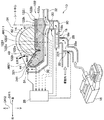
(第1実施形態)
図1は、本実施形態の車両用シート空調装置10とその車両用シート空調装置10が取り付けられた車両用シート12とを示した概略斜視図である。車両用シート12のシートバック121とシートクッション122とのそれぞれに車両用シート空調装置が取り付けられているが、本発明が適用された車両用シート空調装置10(以下、単にシート空調装置10という)は、シートクッション122に取り付けられた車両用シート空調装置である。なお、図1において矢印DR1は車両の左右方向DR1すなわち車両幅方向DR1を表し、矢印DR2は車両の上下方向DR2すなわち車両上下方向DR2を表し、矢印DR3は車両の前後方向DR3すなわち車両前後方向DR3を表している。
(First embodiment)
FIG. 1 is a schematic perspective view showing a vehicle
図1に示す車両用シート12は、車両用シート12に着座している乗員すなわち着座者の背もたれとなるシートバック121と、その着座者の座部として機能し着座者の臀部および大腿部14を支持するシートクッション122とを備えている。車両用シート12は、車両幅方向DR1に対称的な形状をなしている。本実施形態では、シートクッション122が本発明のシート構成部材に対応する。
A
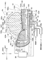
図2は、図1の車両用シート12を見易く表示した車両用シート12の斜視図である。図3は、図1のIII−III断面図であって、シートクッション122およびシート空調装置10の断面図である。図3では、シートクッション122上に着座者の大腿部14が断面図示されている。また、シートクッション122およびシート空調装置10は車両幅方向DR1において略対称形状を成しているので、図3では、車両幅方向DR1での車両左側半分の図示を省略している。この図示の省略は、後述の図4および図7でも同様である。
FIG. 2 is a perspective view of the
図2および図3に示すように、車両用シート12のシートクッション122は、弾力性を有する発砲ウレタン性のシートパッド122aと、シートパッド122aの着座者側の表面を覆うシート表皮122bとから構成されている。
As shown in FIGS. 2 and 3, the
シート表皮122bは、シートパッド122aの外形形状に沿うことができるように立体的に縫製されていると共に、吊り込み構造によりシートパッド122aの外形形状に追従している。その吊り込み構造は、シート表皮122bの裏面側に設けられた吊込みワイヤ122cをシートパッド122aに埋設されたインサートワイヤ122dに係止することにより、シートパッド122aの表面に形成された吊込み溝122eにシート表皮122bを吊り込む構成となっている。
The
この吊込みワイヤ122cおよびインサートワイヤ122dから成る吊込み部122fは、図2に示すように、車両幅方向DR1に並んで一対をなすように配置されており、シートクッション122の着座者側の表面形状に沿って車両前後方向DR3に延びるようにそれぞれ形成されている。そして、吊込み部122fは、図3に示すように、シート表皮122bをシートパッド122aへ接合している表皮接合部として機能している。
As shown in FIG. 2, the
図2に示すように、シートクッション122の着座者側表面は、車両幅方向DR1に並んだ3つの部位、すなわち、右側シート周縁部122hと左側シート周縁部122iとそれらシート周縁部122h、122iの間に挟まれた中央着座部122jとから構成されている。その2つのシート周縁部122h、122iは中央着座部122jを挟んで対称的な形状をなしている。中央着座部122jの着座者側には、その着座者である乗員を支持する乗員支持面122k(図3参照)が形成されている。すなわち、中央着座部122jは乗員に直接接触して乗員を支持する乗員支持部である。
As shown in FIG. 2, the seat cushion side surface of the
車両幅方向DR1において、右側シート周縁部122hと中央着座部122jとは一対の吊込み部122fのうちの一方を介して隣接し、左側シート周縁部122iと中央着座部122jとは一対の吊込み部122fのうちの他方を介して隣接している。すなわち、中央着座部122jは、シートクッション122において一対の吊込み部122fの間を構成しており、シート周縁部122h、122iは、シートクッション122において一対の吊込み部122fの各々に対し車両幅方向DR1における外側を構成している。なお、シートバック121の構造も上記したシートクッション122の構造と同様である。
In the vehicle width direction DR1, the right seat
図1および図3に示すように、シート空調装置10は車両用シート12に設けられ、シートクッション122の下方から側方にかけて設置されている。シート空調装置10は、車室内空調ユニット16からの空気または車室内の空気を吸い込み、その空気を加熱した温風を車両幅方向DR1におけるシートクッション122の両側から着座者の左右それぞれの大腿部14の表面に吹き付ける空調装置である。要するに、シート空調装置10は、車両用シート12まわりから着座者へ温風を吹き出す空調装置である。なお、車室内空調ユニット16は、エバポレータおよびヒータコアを備えインストルメントパネル内に配置された一般的な空調ユニットであり、車室外に設けられた熱交換器により加熱または冷却される冷媒が循環されることにより車室内の空調を行う。
As shown in FIGS. 1 and 3, the
図3に示すように、シート空調装置10は、送風機18、熱交換器20、導入空気切替装置22、吹出方向変更装置24、それらをつなぐ通風管、および制御装置26等を備えている。送風機18は、空気吸入口18aから吸い込んだ空気を空気吹出口18bから吹き出す電動の遠心式送風機である。送風機18は、制御装置26からの制御信号に従って回転して送風する。
As shown in FIG. 3, the
送風機18の空気吸入口18aには吸入通風管28の一端が接続されており、その吸入通風管28の他端には、導入空気切替装置22が配設されている。その導入空気切替装置22は、回動ドア221と、その回動ドア221を制御装置26からの制御信号に従って回動するアクチュエータとを備えている。
One end of a
導入空気切替装置22は、回動ドア221の回動位置に応じて、吸入通風管28の他端である空気吸入部28aを、車室内の空気を吸入通風管28に導入可能とする一方で車室内空調ユニット16からの空気導入を遮断する第1導入状態と、車室内からの空気導入を遮断する一方で車室内空調ユニット16からの空気を吸入通風管28に導入可能とする第2導入状態とに択一的に切り替える。このようにして、送風機18の空気吸入口18aには、車室内の空気または車室内空調ユニット16からの空気が導かれる。この車室内空調ユニット16からの空気は、例えば車室内空調ユニット16のフット吹出口に接続された配管から分岐した配管によって導かれるものであり、車室内空調ユニット16内のエバポレータを通った空調風である。なお、導入空気切替装置22および吸入通風管28は本発明の空気導入部に対応する。
The introduction
熱交換器20は、送風機18が送風する空気を加熱する加熱用熱交換器であり、例えば、PTCヒータで構成されている。そのPTCヒータは、詳細に言えば、所定温度にて電気抵抗値が急増する正の抵抗温度特性を有する電気抵抗体で構成されている。熱交換器20と送風機18の空気吹出口18bとの間には中継通風管30が設けられており、熱交換器20の空気流入側は中継通風管30を介して送風機18の空気吹出口18bに接続されている。
The
熱交換器20の空気流出側には吹出用通風管32が接続されており、その吹出用通風管32は車両幅方向DR1の一方と他方とにそれぞれ分岐している。吹出用通風管32における熱交換器20側とは反対側の端部は車室内へ開放されており、送風機18によって送風されて熱交換器20から導かれた空気を吹き出す空気吹出部321となっている。その空気吹出部321は、送風機18が送風する空気を着座者に向けて吹き出すように開口している。
A
詳細に言えば、空気吹出部321は、車両幅方向DR1においてシートクッション122に隣接するようにしてそのシートクッション122の外側に配置されている。そして、空気吹出部321は、中央着座部122jのまわりにおいて着座者側に開口している。なお、吸入通風管28、中継通風管30、および吹出用通風管32は、例えば一体的に構成された樹脂製のダクト部材を構成している。
Specifically, the
図3に示すように、吹出方向変更装置24は、吹出用通風管32の空気吹出部321に配設されており、空気吹出部321が吹き出す空気の吹出方向を変更する。この吹出方向変更装置24は導風部材241と、その導風部材241を制御装置26からの制御信号に従って回動するアクチュエータとを備えている。その導風部材241は、空気吹出部321が吹き出す空気の吹出方向を変える導風板である。吹出方向変更装置24は本発明の吹出方向変更手段に対応する。
As shown in FIG. 3, the blowing
吹出方向変更装置24は、中央着座部122jの乗員支持面122k上を占める乗員空間34へ向けて空気吹出部321から空気を吹き出させるものであるが、導風部材241の回動位置に応じて空気吹出部321の空気吹出方向を連続的に変化させる。例えば、吹出方向変更装置24は、図3の矢印AR01で示すような車両用シート12における内向きの方向、または、図4の矢印AR02で示すような矢印AR01に比して上向きになる方向へ空気吹出部321の空気吹出方向を変化させる。なお、図4は、図3と同様に図1のIII−III断面図であるが、空気吹出部321が空気を図3とは異なる吹出方向へ吹き出している状態を表している。また、上記乗員空間34とは、乗員支持面122k上を占める三次元的な範囲を意味するので、乗員支持面122k上に着座者が居ても居なくても変わるものではない。
The blowing
図3に示す制御装置26は、CPU、ROM、RAM等からなる周知のマイクロコンピュータとその周辺回路とから構成された電子制御装置であり、ROM等に予め記憶されたコンピュータプログラムに従って種々の制御処理を実行する。制御装置26は本発明の制御手段に対応する。
The
シート空調装置10は、一般的なシート空調装置が有するセンサ類を備えている。それに加え、図3に示すように、第1荷重センサ41と第2荷重センサ42と第3荷重センサ43と第4荷重センサ44とを備えている。これらに荷重センサ41、42、43、44はシートクッション122のシートパッド122a内に内蔵されており、着座者側からの荷重すなわち着座者による荷重を検出する。なお、図1では、図1を見易く表示するために、荷重センサ41、42、43、44の全部を図示してはいない。
The
図3に示す第1荷重センサ41、第2荷重センサ42、第3荷重センサ43、および第4荷重センサ44は、車両幅方向DR1に延びる一列上に車両用シート12のシート中心から外側へ順に配置されている。そして、シート中心を基準として対称的に配置されているので、第1荷重センサ41は1つ設けられ、第2〜4荷重センサ42、43、44はそれぞれ2つずつ設けられている。
The
詳細に言うと、車両幅方向DR1において、第1荷重センサ41はシート中心に配置され、第2荷重センサ42はその第1荷重センサ41を挟んだ対称位置に一対を成すように配置され、第3荷重センサ43は第1、第2荷重センサ41、42を挟んだ対称位置に一対を成すように配置され、第4荷重センサ44は第1〜3荷重センサ41、42、43を挟んだ対称位置に一対を成すように配置されている。また、第1、第2荷重センサ41、42はシートクッション122のうち中央着座部122jに設けられ、第3、第4荷重センサ43、44はシート周縁部122h、122iに設けられている。
More specifically, in the vehicle width direction DR1, the
制御装置26には、荷重センサ41、42、43、44等のセンサから検出信号が逐次入力され、制御装置26は、送風機18、熱交換器20、導入空気切替装置22、および吹出方向変更装置24などを作動させて種々の空調制御を実行する。例えば、制御装置26は、後述する図5の制御処理を実行する。
Detection signals are sequentially input from the sensors such as
図5は、制御装置26の制御処理を示すフローチャートである。例えば、シート空調装置10は、乗員に操作される不図示のシート空調スイッチがオンにされると動作状態となり、制御装置26は、送風機18に送風を開始させると共に熱交換器20に送風空気の加熱を開始させる。そして、図5のフローチャートに示す制御処理を周期的に繰り返し実行する。
FIG. 5 is a flowchart showing the control process of the
先ず、図5のS101では、制御装置26は、各荷重センサ41、42、43、44からそれらの検出値である荷重をそれぞれ取得する。S101の次はS102へ進む。
First, in S101 of FIG. 5, the
S102では、予め定められた関係である図6の吹出方向マップMAP1に従って各荷重センサ41、42、43、44の検出値に基づき、空気吹出部321の空気吹出方向すなわち吹出方向変更装置24の導風部材241の向きを決定する。
In S102, the air blowing direction of the
図6の吹出方向マップMAP1は、空気吹出部321から吹き出される空気が着座者の所定部位またはその着座者まわりの所定部位に向かうように実験的に予め定められている。その所定部位とは、図3において空気吹出部321から着座者の大腿部14を見たときのその大腿部14の頂点またはその頂点まわりの空間である。このように吹出方向マップMAP1が定められているのは、図3の矢印AR01または図4のAR02のように空調空気が空気吹出部321から着座者の体表面である大腿部14表面に沿うように吹き出されると、その空調空気の流れは、図3の矢印AR011または図4のAR021のようにコアンダ効果によって大腿部14表面に沿ったコアンダ流となり車両用シート12の中央にまで届き易くなるからである。
The blowing direction map MAP1 of FIG. 6 is experimentally determined in advance so that the air blown from the
具体的に、図6の吹出方向マップMAP1は、着座者の体重が大きいほど又はシートクッション122上において着座者の大腿部14の位置が車両幅方向DR1の外側にあるほど、空気吹出部321の空気吹出方向が車両用シート12における内向きから上向きに変化するように定められている。
Specifically, the blowing direction map MAP1 of FIG. 6 indicates that the
制御装置26が大腿部14の位置を認識するために、各荷重センサ41、42、43、44が検出する荷重に対して、その荷重センサ上に大腿部14が乗っているか否かを判定するための荷重閾値が予め実験的に定められている。そして、制御装置26は、各荷重センサ41、42、43、44のそれぞれについて、その荷重センサにより検出される荷重が上記荷重閾値以上であれば荷重センサがオン状態であると判定し、荷重閾値未満であれば荷重センサがオフ状態であると判定する。
In order for the
その判定の結果、制御装置26は、オン状態の荷重センサが車両幅方向DR1の外側に存するほど着座者の大腿部14が車両幅方向DR1の外側に位置していると認識し、その認識に基づいて、図6において着座者の体重から空気吹出方向を決める関係としてL01〜L04の関係の何れかを選択する。
As a result of the determination, the
具体的に説明すると、例えば第2〜4荷重センサ42、43、44がオフ状態であれば、上記空気吹出方向を決める関係としてL01の関係を選択する。
More specifically, for example, if the second to
また、第3、第4荷重センサ43、44がオフ状態であり且つ第2荷重センサ42がオン状態であれば、第2〜4荷重センサ42、43、44がオフ状態である場合よりは大腿部14がシートクッション122上において車両幅方向DR1外側に位置していると認識し、上記空気吹出方向を決める関係としてL02の関係を選択する。
In addition, if the third and
また、第4荷重センサ44がオフ状態であり且つ第3荷重センサ43がオン状態であれば、第3、第4荷重センサ43、44がオフ状態であり且つ第2荷重センサ42がオン状態である場合よりは大腿部14が車両幅方向DR1外側に位置していると認識し、上記空気吹出方向を決める関係としてL03の関係を選択する。
If the
また、第4荷重センサ44がオン状態であれば、第4荷重センサ44がオフ状態であり且つ第3荷重センサ43がオン状態である場合よりは大腿部14が車両幅方向DR1外側に位置していると認識し、上記空気吹出方向を決める関係としてL04の関係を選択する。
Further, when the
なお、同一の体重の下でL01〜L04の関係を相互に比較すると、図6から判るように、L01の関係から決定される空気吹出方向はL02の関係から決定される場合よりも内向きになる。また、L02の関係から決定される空気吹出方向はL03の関係から決定される場合よりも内向きになる。また、L03の関係から決定される空気吹出方向はL04の関係から決定される場合よりも内向きになる。 When the relationship between L01 and L04 is compared with each other under the same body weight, as can be seen from FIG. 6, the air blowing direction determined from the relationship of L01 is more inward than when determined from the relationship of L02. Become. Further, the air blowing direction determined from the relationship of L02 is inward from the case determined from the relationship of L03. Further, the air blowing direction determined from the relationship of L03 is inward from the case determined from the relationship of L04.
例えば、図4に表されている大腿部14は、図3に表されている大腿部14と比較してシートクッション122上において車両幅方向DR1外側に位置している。そして、図4では大腿部14が第4荷重センサ44上に位置し第4荷重センサ44がオン状態であるので、この場合にはL04の関係が選択される。その一方で、図3では大腿部14が第3、第4荷重センサ43、44上には位置しておらず第3、第4荷重センサ43、44がオフ状態であるが、大腿部14が第2荷重センサ42上には位置し第2荷重センサ42がオン状態であるので、この場合には、L04の関係よりも空気吹出部321の空気吹出方向が内向きに決定されるL02の関係が選択される。
For example, the
制御装置26は、このように大腿部14の位置を認識すると共にL01〜L04の関係の何れか1つを選択すると、それと共に、荷重センサ41、42、43、44の検出値から着座者の体重を算出する。例えば、荷重センサ41、42、43、44のそれぞれが検出した荷重を合計して着座者の体重を算出する。着座者の体重が大きいほどその体格も大きくなり大腿部14が太くなると推定できるからである。そして、大腿部14が太いほど、大腿部14の高さが高くなり空気吹出部321の空気吹出方向を上向きにする必要があるからである。
When the
制御装置26は、L01〜L04の関係の中の何れかを選択し着座者の体重を算出すると、L01〜L04の関係の中から選択した関係に従って、着座者の体重に基づき空気吹出部321の空気吹出方向を決定する。S102にて空気吹出部321の空気吹出方向を決定すると、次はS103へ進む。
When the
S103では、S102で決定した空気吹出部321の空気吹出方向で空気吹出部321が空調空気を吹き出すように、吹出方向変更装置24に空気吹出部321の空気吹出方向を変更させる。具体的には、吹出方向変更装置24のアクチュエータへ制御信号を出力し、それにより、S102で決定した空気吹出方向で空気吹出部321が空調空気を吹き出すように吹出方向変更装置24の導風部材241を回動させる。
In S103, the blowing
上述のように、制御装置26は、荷重センサ41、42、43、44の検出値である各荷重から、着座者の体格を推定できる体重と、大腿部14の位置である着座姿勢とを求め、その求めた体重および着座姿勢に基づいて吹出方向変更装置24の導風部材241を回動させる。従って、制御装置26は、着座者である乗員の体格と着座姿勢とから構成された乗員情報に基づき吹出方向変更装置24に空気吹出部321の空気吹出方向を変更させる制御手段として機能している。
As described above, the
なお、上述した図5の各ステップでの処理は、それぞれの機能を実現する手段を構成している。 Note that the processing in each step of FIG. 5 described above constitutes a means for realizing each function.
上述したように、本実施形態によれば、制御装置26は、着座者である乗員の体格と着座姿勢とから構成された乗員情報に基づき、吹出用通風管32の空気吹出部321が吹き出す空気の吹出方向を吹出方向変更装置24に変更させるので、乗員の体格または着座姿勢に応じた向きに空気を吹き出すことができる。
As described above, according to the present embodiment, the
また、本実施形態によれば、図6の吹出方向マップMAP1は、空気吹出部321から吹き出される空調空気が、図3において空気吹出部321から着座者の大腿部14を見たときのその大腿部14の頂点またはその頂点まわりの空間へ向かうように予め定められているので、その空調空気は、コアンダ効果によって図3の矢印AR011または図4のAR021のように流れ車両用シート12の中央にまで届き易くなる。そのため、着座者へ十分に暖房されているという感覚を提供することができる。
Further, according to the present embodiment, the blowing direction map MAP1 in FIG. 6 is obtained when the conditioned air blown from the
また、本実施形態によれば、図6の吹出方向マップMAP1は、具体的には、着座者の体重が大きいほど又はシートクッション122上において着座者の大腿部14の位置が車両幅方向DR1の外側にあるほど、空気吹出部321の空気吹出方向が車両用シート12における内向きから上向きに変化するように定められているので、着座者の体格および着座姿勢に合わせて、空気吹出部321の空気吹出方向をコアンダ効果が生じ易いように決定することができる。そのため、着座者の体格または着座姿勢が変わっても着座者の快適性を維持することが可能である。
In addition, according to the present embodiment, the blowing direction map MAP1 of FIG. 6 specifically indicates that the position of the
また、本実施形態によれば、空気吹出部321は、車両幅方向DR1においてシートクッション122に隣接するように配置されているので、空気吹出部321は着座者の大腿部14に近く、空調空気が空気吹出部321から着座者の大腿部14に至るまでに生じる熱拡散を抑えることができる。そのため、効率的に着座者へ快適感を提供することが可能である。
Moreover, according to this embodiment, since the
また、本実施形態によれば、送風機18は吸入通風管28を通じて車室内空調ユニット16で調温された空気を吸い込むことができるので、その車室内空調ユニット16の空調能力を利用してシート空調を行うことが可能である。
Further, according to the present embodiment, since the
(第2実施形態)
次に、本発明の第2実施形態について説明する。本実施形態では、前述の第1実施形態と異なる点を主として説明し、第1実施形態と同一または均等な部分については省略または簡略化して説明する。後述の第3実施形態以降でも同様である。
(Second Embodiment)
Next, a second embodiment of the present invention will be described. In the present embodiment, differences from the first embodiment will be mainly described, and the same or equivalent parts as those in the first embodiment will be omitted or simplified. The same applies to third and later embodiments described later.
図7は、本実施形態のシートクッション122およびシート空調装置10の断面図であって、第1実施形態の図3に相当する図である。図7に示すように、本実施形態の吹出用通風管32はシートクッション122の側方には回り込んでおらず、吹出用通風管32は空気吹出部321(図3参照)を有していない。吹出用通風管32における熱交換器20側とは反対側の端部322は、シートクッション122の下側からシートパッド122aに形成された第1通風路122nに接続されている。
FIG. 7 is a cross-sectional view of the
このシートパッド122aの第1通風路122nは、熱交換器20からの空気をシート表面の全体へ送ることができるようにシートパッド122a内で枝分かれしており、シート表皮122bに向けて開放されている。このように形成された第1通風路122nは、送風機18が送風する空気をシート表皮122bの複数の微細孔122qへ送る。
The
シートクッション122の乗員支持面122kを含むシート表皮122bは、複数の微細孔122qが形成されているパーフォレーション付き表皮である。シート表皮122bは、例えば天然皮革または人工皮革で構成されている。そのシート表皮122bの微細孔122qはそれぞれ直径1mm程度の通風孔であり、送風機18により送風され熱交換器20から第1通風路122nを通って導かれた空気を着座者に対して吹き出す。
The
また、シートパッド122aには、送風機18が送風する空気をベゼル52の空気吹出部522へ送る第2通風路122pが形成されている。詳細には、第2通風路122pの一端が第1通風路122nに接続され、第2通風路122pの他端がベゼル52のベゼル通風路521に接続されている。そのため、送風機18が送風する空気は、第1通風路122nを介して第2通風路122pへ流入する。
In addition, a
本実施形態のシート空調装置10はベゼル52を備えている。そのベゼル52は、シートクッション122よりも硬度が高く弾性を有するゴムなど弾性部材で構成されている。ベゼル52には貫通孔であるベゼル通風路521が形成されており、ベゼル52はそのベゼル通風路521が第2通風路122pに接続されるようにシートクッション122の右側シート周縁部122hへ上側すなわち着座者側から差し込まれている。このことは左側シート周縁部122i(図2参照)でも同様である。
The
ベゼル52においてシートクッション122上に開口している端部は、車室内へ開放され熱交換器20から導かれた空気を吹き出す空気吹出部522となっている。すなわち、本実施形態の空気吹出部522は、右側シート周縁部122hと左側シート周縁部122iとにそれぞれ設けられている。
An end portion of the
本実施形態の吹出方向変更装置24はベゼル52の空気吹出部522に配設されているが、それ以外の点では第1実施形態のものと同じである。例えば、吹出方向変更装置24は、ベゼル52の空気吹出部522の空気吹出方向を図7の矢印ARwの範囲で変化させることができる。
The blowing
上述したように、本実施形態によれば、第1実施形態と同様に、空気吹出部522の空気吹出方向が着座者の体格と着座姿勢とに基づいて変更されるので、それによる第1実施形態と同様の効果を得ることができる。
As described above, according to the present embodiment, as in the first embodiment, the air blowing direction of the
また、本実施形態によれば、熱交換器20を通った温風が、複数の微細孔122qから吹き出されると同時に空気吹出部522からも吹き出されるので、高い快適性を着座者に提供することができる。
Further, according to the present embodiment, the warm air that has passed through the
また、本実施形態によれば、第2通風路122pは第1通風路122nへ接続されており、送風機18が送風する空気は、第1通風路122nを介して第2通風路122pへ流入するので、吹出用通風管32が第1通風路122nに加えて第2通風路122pへ接続される必要がなく、配管の簡素化を図ることができる。
Moreover, according to this embodiment, the
(第3実施形態)
次に、本発明の第3実施形態について説明する。本実施形態では、前述の第1実施形態と異なる点を主として説明する。
(Third embodiment)
Next, a third embodiment of the present invention will be described. In the present embodiment, differences from the first embodiment will be mainly described.
図8は、本実施形態の車両用シート空調装置10とその車両用シート空調装置10が取り付けられた車両用シート12とを示した概略斜視図である。図8に示すように、本実施形態は第1実施形態と比較して空気吹出部321の配置位置が異なっている。具体的には、空気吹出部321は、その空気吹出部321から着座者の下腿へ向けて空調空気が吹き出されるように配置されている。空気吹出部321に設けられている吹出方向変更装置24は、矢印AR1wd、AR2wdで示す空気吹出部321の空気吹出方向を、矢印AR1h、AR2hのように車両幅方向DR1に変化させることができる。
FIG. 8 is a schematic perspective view showing the vehicle
着座者の下腿裏へ向けて空調空気を吹き付ける場合、着座者の左右それぞれの脚の開き方により車両幅方向DR1における下腿の位置が大きく異なる。そのため、空気吹出部321の空気吹出方向が不適当である場合には、空気吹出部321からの空調空気が下腿前方に抜けやすく、そうなれば高い快適性を提供することが困難である。
When air-conditioned air is blown toward the lower leg of the seated person, the position of the lower leg in the vehicle width direction DR1 varies greatly depending on how the left and right legs of the seated person are opened. For this reason, when the air blowing direction of the
そこで、本実施形態のシート空調装置10は、複数の荷重センサ58をシートクッション122に有し、制御装置26(図3参照)はその複数の荷重センサ58のそれぞれの検出信号に基づいて、着座者の着座姿勢、具体的には下腿の位置を推定する。そして、制御装置26は、その着座者の着座姿勢である乗員情報に基づき、吹出方向変更装置24に空気吹出部321の空気吹出方向を変更させる。
Therefore, the
詳細に説明すると、本実施形態の複数の荷重センサ58は第1実施形態の荷重センサ41〜44と同じものであり、第1実施形態と同様に、車両幅方向DR1に並んで且つシート中心を基準として対称的に配置されている。図8では荷重センサ58が車両幅方向DR1に2列並んでいる。
More specifically, the plurality of
そして、制御装置26は、図5のフローチャートに従って制御処理を実行する。すなわち、図5のS101において、制御装置26は、複数の荷重センサ58からそれらの検出値をそれぞれ取得する。
And the
続くS102では、制御装置26は、第1実施形態と同様に荷重センサ58のオン状態またはオフ状態を判定し、オン状態の荷重センサ58が車両幅方向DR1の外側に存するほど着座者の下腿が車両幅方向DR1の外側に位置していると認識する。そして、制御装置26は、その認識した下腿位置に基づき空気吹出部321の空気吹出方向を決定する。例えば、車両幅方向DR1において、上記認識した下腿位置が外側であるほど、空気吹出部321の空気吹出方向も外側に向ける。
In subsequent S102, the
続くS103では、第1実施形態と同様に、S102で決定した空気吹出部321の空気吹出方向で空気吹出部321が空調空気を吹き出すように、吹出方向変更装置24に空気吹出部321の空気吹出方向を変更させる。なお、図8では、図8を見易く表示するために、車両幅方向DR1における左側の荷重センサ58の図示が省略されている。
In subsequent S103, as in the first embodiment, the
本実施形態によれば、制御装置26は、荷重センサ58の検出信号に基づいて着座者の下腿位置を認識し、その認識した下腿位置に向けて空気吹出部321の空気吹出方向を定めるので、煩わしい操作を必要とせずに、着座者の下腿まわりの快適性を向上させることが可能である。
According to the present embodiment, the
(第4実施形態)
次に、本発明の第4実施形態について説明する。本実施形態では、前述の第1実施形態と異なる点を主として説明する。
(Fourth embodiment)
Next, a fourth embodiment of the present invention will be described. In the present embodiment, differences from the first embodiment will be mainly described.
図9は、本実施形態の車両用シート空調装置10とその車両用シート空調装置10が取り付けられた車両用シート12とを示した概略斜視図である。図9に示すように、本実施形態のシート空調装置10は第1実施形態と異なりシートバック121に設けられている。そして、本実施形態は第1実施形態と比較して空気吹出部321の配置位置が異なっている。具体的には、空気吹出部321は、その空気吹出部321から着座者の首または肩へ向けて空調空気が吹き出されるようにシートバック121の上端に配置されている。空気吹出部321に設けられている吹出方向変更装置24は、空気吹出部321の空気吹出方向を、矢印AR3vのように車両上下方向DR2に変化させることができる。
FIG. 9 is a schematic perspective view showing the vehicle
着座者の首または肩へ空調空気を吹き付ける際、着座者個々の肩首の高さ方向の位置が異なる。要するに、着座者個々の座高が異なる。また、空調空気が着座者の頭または頬に直接当たると快適性を損なうおそれがある。 When air-conditioned air is blown to the seated person's neck or shoulder, the height of the seated person's shoulder neck differs. In short, the sitting height of each seated person is different. In addition, if the conditioned air directly hits the seated person's head or cheek, the comfort may be impaired.
そこで、本実施形態のシート空調装置10は、複数の荷重センサ60をシートバック121に有し、着座者の体重を検出するための体重センサ62をシートクッション122に有している。また、制御装置26(図3参照)は、体重センサ62の検出信号から着座者の体重を取得すると共に、複数の荷重センサ60のそれぞれの検出信号に基づいて、着座者の上半身の幅を推定する。そして、制御装置26は、この体重および上半身の幅から得られる着座者の座高すなわち着座者の体格である乗員情報に基づき、吹出方向変更装置24に空気吹出部321の空気吹出方向を変更させる。
Therefore, the
詳細に説明すると、本実施形態の複数の荷重センサ60は第1実施形態の荷重センサ41〜44と同じものであり、車両幅方向DR1において1列に並んで且つシート中心を基準として対称的に配置されている。
More specifically, the plurality of
そして、制御装置26は、図5のフローチャートに従って制御処理を実行する。すなわち、図5のS101において、制御装置26は、複数の荷重センサ60と体重センサ62とからそれらの検出値をそれぞれ取得する。
And the
続くS102では、制御装置26は、第1実施形態と同様に荷重センサ60のオン状態またはオフ状態を判定し、オン状態の荷重センサ60が車両幅方向DR1の外側に存するほど着座者の上半身の幅が車両幅方向DR1に広いと認識する。
In subsequent S102, the
そして、制御装置26は、第1実施形態の吹出方向マップMAP1(図6参照)に相当する予め定められた図10の吹出方向マップMAP2に従って、上記認識した上半身の幅と体重センサ62により検出された体重とに基づき空気吹出部321の空気吹出方向を決定する。
Then, the
ここで、同一体重で比較すれば着座者の上半身の幅が狭いほど座高は高くなり、同一の上半身の幅で比較すれば体重が大きいほど座高は高くなると考えられる。従って、図10の吹出方向マップMAP2は、上半身の幅が狭いほど又は体重が大きいほど、車両上下方向DR2において空気吹出部321の空気吹出方向が上向きになるように定められている。
Here, when compared with the same weight, the seat height increases as the width of the upper body of the seated person decreases. When compared with the width of the same upper body, the seat height increases as the weight increases. Therefore, the blowing direction map MAP2 of FIG. 10 is determined such that the air blowing direction of the
続くS103では、第1実施形態と同様に、S102で決定した空気吹出部321の空気吹出方向で空気吹出部321が空調空気を吹き出すように、吹出方向変更装置24に空気吹出部321の空気吹出方向を変更させる。
In subsequent S103, as in the first embodiment, the
本実施形態によれば、制御装置26は、荷重センサ60および体重センサ62の検出信号に基づいて、着座者の首及び肩の位置すなわち着座者の座高を推定し、その推定した首または肩の位置に向けて空気吹出部321の空気吹出方向を定めるので、煩わしい操作を必要とせずに、着座者の首または肩まわりの快適性を向上させることが可能である。
According to the present embodiment, the
(他の実施形態)
(1)上述の第1、第2実施形態において、図5のS102では、空気吹出部321の空気吹出方向は、着座者の体格と着座姿勢とから構成された乗員情報に基づいて決定されるが、その乗員情報は着座者の体格と着座姿勢との一方だけで構成されていてもよい。すなわち、乗員情報とは、着座者の体格や着座姿勢を含む着座者の態様を表すものであればよく、S102では、空気吹出部321の空気吹出方向が着座者の体格と着座姿勢との一方に基づいて決定されても差し支えない。
(Other embodiments)
(1) In the first and second embodiments described above, in S102 of FIG. 5, the air blowing direction of the
(2)上述の第1〜3実施形態において、空気吹出部321、522は車両幅方向DR1において左右一対を成すように合計2つ設けられているが、その2つのうちの一方だけが設けられており他方が設けられていなくても差し支えない。
(2) In the first to third embodiments described above, a total of two
(3)上述の各実施形態において、着座者の体格および着座姿勢を認識するために荷重センサ41、42、43、44等が用いられているが、それに限らず、例えば、車室内において車両用シート12とは別個に配置された光学センサ、超音波センサ、または赤外線センサ等が用いられても差し支えない。
(3) In each of the above-described embodiments, the
(4)上述の各実施形態において、送風機18は遠心式送風機であるが、その形式に限定はなく、例えば軸流式送風機であっても差し支えない。
(4) In each above-mentioned embodiment, although the
(5)上述の各実施形態において、熱交換器20は、例えばPTCヒータであるが、PTCヒータなどの電気ヒータに限られるわけではなく、他の方式の加熱器であっても差し支えない。
(5) In each of the above-described embodiments, the
(6)上述の各実施形態において、シート空調装置10は温風を吹き出す空調装置であるが、冷風を吹き出す空調装置であっても差し支えない。その場合には、熱交換器20は加熱用熱交換器ではなく、送風機18が送風する空気を冷却する冷却用熱交換器である。その冷却用熱交換器は、例えばペルチェ素子などで構成されている。
(6) In each embodiment described above, the
(7)上述の各実施形態では、送風機18の空気吸入口18aには車室内の空気または車室内空調ユニット16からの空気が導入されるが、その空気吸入口18aにその何れか一方が導入されるだけであっても差し支えない。そのようにした場合には、導入空気切替装置22は不要である。
(7) In each of the above-described embodiments, air in the vehicle interior or air from the vehicle interior
(8)上述の第2実施形態において、シート表皮122bは例えば天然皮革または人工皮革で構成されているが、モケット等の織布であっても差し支えない。その場合には、織布の織り目が微細孔122qとして機能する。
(8) In the second embodiment described above, the
(9)上述の第2実施形態において、吹出用通風管32は第1通風路122nに接続され、送風機18が送風する空気は、第1通風路122nを介して第2通風路122pへ流入するが、逆に、吹出用通風管32が第2通風路122pに接続され、送風機18が送風する空気が、第2通風路122pを介して第1通風路122nへ流入しても差し支えない。
(9) In the second embodiment described above, the
(10)上述の第1、第2実施形態において、シート空調装置10はシートクッション122に設けられているが、シートバック121に設けられていても差し支えない。その場合には、シートバック121が本発明のシート構成部材に対応する。
(10) In the first and second embodiments described above, the
(11)上述の第1、第2実施形態において、着座者の体重は、例えば荷重センサ41、42、43、44のそれぞれが検出した荷重を合計して算出されるが、単純に合計するだけでなく、その合計した合計値に所定の係数を乗じて得た値を体重としてもよいし、その合計値に所定値を加算して得た値を体重としてもよい。
(11) In the first and second embodiments described above, the weight of the seated person is calculated by adding up the loads detected by the
(12)上述の各実施形態において、図5のフローチャートに示す各ステップの処理はコンピュータプログラムによって実現されるものであるが、ハードロジックで構成されるものであっても差し支えない。 (12) In each of the above-described embodiments, the processing of each step shown in the flowchart of FIG. 5 is realized by a computer program, but may be configured by hardware logic.
なお、本発明は上記した実施形態に限定されるものではなく、特許請求の範囲に記載した範囲内において適宜変更が可能である。また、上記各実施形態は、互いに無関係なものではなく、組み合わせが明らかに不可な場合を除き、適宜組み合わせが可能である。例えば、第3実施形態を第1実施形態または第2実施形態と組み合わせてもよいし、第4実施形態を第1実施形態または第2実施形態と組み合わせてもよい。また、第1実施形態と第2実施形態とを組み合わせて、シートクッション122に形成された複数の微細孔122qから空調空気を吹き出させると共に、シートクッション122の外側に隣接した空気吹出部321から空調空気を吹き出させてもよい。
In addition, this invention is not limited to above-described embodiment, In the range described in the claim, it can change suitably. Further, the above embodiments are not irrelevant to each other, and can be combined as appropriate unless the combination is clearly impossible. For example, the third embodiment may be combined with the first embodiment or the second embodiment, and the fourth embodiment may be combined with the first embodiment or the second embodiment. In addition, by combining the first embodiment and the second embodiment, air-conditioned air is blown out from the plurality of
また、上記各実施形態において、実施形態を構成する要素は、特に必須であると明示した場合および原理的に明らかに必須であると考えられる場合等を除き、必ずしも必須のものではないことは言うまでもない。また、上記各実施形態において、実施形態の構成要素の個数、数値、量、範囲等の数値が言及されている場合、特に必須であると明示した場合および原理的に明らかに特定の数に限定される場合等を除き、その特定の数に限定されるものではない。また、上記各実施形態において、構成要素等の材質、形状、位置関係等に言及するときは、特に明示した場合および原理的に特定の材質、形状、位置関係等に限定される場合等を除き、その材質、形状、位置関係等に限定されるものではない。 In each of the above-described embodiments, it is needless to say that elements constituting the embodiment are not necessarily essential unless explicitly stated as essential and clearly considered essential in principle. Yes. Further, in each of the above embodiments, when numerical values such as the number, numerical value, quantity, range, etc. of the constituent elements of the embodiment are mentioned, it is clearly limited to a specific number when clearly indicated as essential and in principle. The number is not limited to the specific number except for the case. In each of the above embodiments, when referring to the material, shape, positional relationship, etc. of the constituent elements, etc., unless otherwise specified, or in principle limited to a specific material, shape, positional relationship, etc. The material, shape, positional relationship, etc. are not limited.
10 車両用シート空調装置
12 車両用シート
18 送風機
321、522 空気吹出部
24 吹出方向変更装置(吹出方向変更手段)
26 制御装置(制御手段)
DESCRIPTION OF
26 Control device (control means)
Claims (12)
その送風機が送風する空気を車両用シート(12)に着座した乗員に向けて吹き出すように開口している空気吹出部(321、522)と、
前記空気吹出部に設けられ、その空気吹出部が吹き出す空気の吹出方向を変更する吹出方向変更手段(24)と、
前記乗員の体格と着座姿勢との少なくとも一方から構成された乗員情報に基づき前記吹出方向変更手段に前記吹出方向を変更させる制御手段(26)とを備えており、
前記車両用シートは、前記乗員を支持する乗員支持部(122j)を有し前記乗員の座部として機能するシートクッション(122)を備え、
前記空気吹出部は、前記シートクッションの乗員支持部のまわりにおいてその乗員側に開口しており、
前記制御手段は、予め定められた関係(MAP1)に従って前記吹出方向変更手段に前記吹出方向を変更させ、
その予め定められた関係は、前記乗員の体重が大きいほど前記吹出方向が前記車両用シートにおける内向きから上向きに変化するように定められていることを特徴とする車両用シート空調装置。 A blower (18) for blowing air;
Air blowing portions (321, 522) that are open so as to blow the air blown by the blower toward the passenger seated on the vehicle seat (12);
A blowing direction changing means (24) that is provided in the air blowing section and changes the blowing direction of the air blown out by the air blowing section;
Control means (26) for causing the blowing direction changing means to change the blowing direction based on occupant information constituted by at least one of the physique and sitting posture of the occupant ,
The vehicle seat includes an occupant support portion (122j) that supports the occupant and includes a seat cushion (122) that functions as a seat portion of the occupant.
The air blowing part is open to the occupant side around the occupant support part of the seat cushion,
The control means causes the blowing direction changing means to change the blowing direction according to a predetermined relationship (MAP1),
The vehicle seat air conditioner is characterized in that the predetermined relationship is determined such that the blowing direction changes from inward to upward in the vehicle seat as the weight of the occupant increases .
その送風機が送風する空気を車両用シート(12)に着座した乗員に向けて吹き出すように開口している空気吹出部(321、522)と、
前記空気吹出部に設けられ、その空気吹出部が吹き出す空気の吹出方向を変更する吹出方向変更手段(24)と、
前記乗員の体格と着座姿勢との少なくとも一方から構成された乗員情報に基づき前記吹出方向変更手段に前記吹出方向を変更させる制御手段(26)とを備えおり、
前記車両用シートは、前記乗員を支持する乗員支持部(122j)を有し前記乗員の座部として機能するシートクッション(122)を備え、
前記空気吹出部は、前記シートクッションの乗員支持部のまわりにおいてその乗員側に開口しており、
前記制御手段は、予め定められた関係(MAP1)に従って前記吹出方向変更手段に前記吹出方向を変更させ、
その予め定められた関係は、前記シートクッション上において前記乗員の大腿部(14)の位置が車両幅方向の外側にあるほど前記吹出方向が前記車両用シートにおける内向きから上向きに変化するように定められていることを特徴とする車両用シート空調装置。 A blower (18) for blowing air;
Air blowing portions (321, 522) that are open so as to blow the air blown by the blower toward the passenger seated on the vehicle seat (12);
A blowing direction changing means (24) that is provided in the air blowing section and changes the blowing direction of the air blown out by the air blowing section;
Control means (26) for causing the blowing direction changing means to change the blowing direction based on occupant information constituted by at least one of the physique and sitting posture of the occupant ,
The vehicle seat includes an occupant support portion (122j) that supports the occupant and includes a seat cushion (122) that functions as a seat portion of the occupant.
The air blowing part is open to the occupant side around the occupant support part of the seat cushion,
The control means causes the blowing direction changing means to change the blowing direction according to a predetermined relationship (MAP1),
The predetermined relationship is that the blowing direction changes from inward to upward in the vehicle seat as the position of the occupant's thigh (14) is on the outer side of the vehicle width direction on the seat cushion. A vehicle seat air-conditioning apparatus characterized by the above .
その送風機が送風する空気を車両用シート(12)に着座した乗員に向けて吹き出すように開口している空気吹出部(321、522)と、
前記空気吹出部に設けられ、その空気吹出部が吹き出す空気の吹出方向を変更する吹出方向変更手段(24)と、
前記乗員の体格と着座姿勢との少なくとも一方から構成された乗員情報に基づき前記吹出方向変更手段に前記吹出方向を変更させる制御手段(26)とを備えており、
前記車両用シートは、前記乗員を支持する乗員支持部(122j)を有し前記乗員の座部として機能するシートクッション(122)を備え、
前記空気吹出部は、前記シートクッションの乗員支持部のまわりにおいてその乗員側に開口しており、
前記制御手段は、予め定められた関係(MAP1)に従って前記吹出方向変更手段に前記吹出方向を変更させ、
その予め定められた関係は、前記シートクッション上において前記乗員の大腿部(14)の位置が車両幅方向の外側にあるほど前記吹出方向が前記車両用シートにおける内向きから上向きに変化し且つ前記乗員の体重が大きいほど前記吹出方向が前記内向きから前記上向きに変化するように定められていることを特徴とする車両用シート空調装置。 A blower (18) for blowing air;
Air blowing portions (321, 522) that are open so as to blow the air blown by the blower toward the passenger seated on the vehicle seat (12);
A blowing direction changing means (24) that is provided in the air blowing section and changes the blowing direction of the air blown out by the air blowing section;
Control means (26) for causing the blowing direction changing means to change the blowing direction based on occupant information constituted by at least one of the physique and sitting posture of the occupant ,
The vehicle seat includes an occupant support portion (122j) that supports the occupant and includes a seat cushion (122) that functions as a seat portion of the occupant.
The air blowing part is open to the occupant side around the occupant support part of the seat cushion,
The control means causes the blowing direction changing means to change the blowing direction according to a predetermined relationship (MAP1),
The predetermined relationship is that, as the position of the occupant's thigh (14) is on the outside of the vehicle width direction on the seat cushion, the blowing direction changes from inward to upward in the vehicle seat and The vehicle seat air conditioner is characterized in that the blowing direction changes from the inward direction to the upward direction as the weight of the passenger increases .
前記制御手段は、予め定められた荷重閾値以上の荷重を検出している前記荷重センサが車両幅方向の外側に存するほど前記大腿部が車両幅方向の外側に位置していると認識することを特徴とする請求項2または3に記載の車両用シート空調装置。 A plurality of load sensors (41 to 44) provided on the seat cushion side by side in the vehicle width direction for detecting a load from the occupant side,
The control means recognizes that the thigh is positioned on the outer side in the vehicle width direction as the load sensor that detects a load equal to or greater than a predetermined load threshold is on the outer side in the vehicle width direction. The vehicle seat air-conditioning apparatus according to claim 2 or 3 .
前記複数の荷重センサの全部または一部が、前記シートクッションにおいて前記一対の表皮接合部の各々に対し車両幅方向における外側を構成するシート周縁部(122h、122i)に設けられていることを特徴とする請求項4に記載の車両用シート空調装置。 The seat cushion comprises a pair of elastic seat pads (122a), a seat skin (122b) that covers the occupant side surface of the seat pads, aligned in the vehicle width direction, and the seat skins A skin joint (122f) joined to the seat pad,
All or a part of the plurality of load sensors is provided on a seat peripheral edge portion (122h, 122i) constituting an outer side in the vehicle width direction with respect to each of the pair of skin joint portions in the seat cushion. The vehicle seat air conditioner according to claim 4 .
その送風機が送風する空気を車両用シート(12)に着座した乗員に向けて吹き出すように開口している空気吹出部(321、522)と、
前記空気吹出部に設けられ、その空気吹出部が吹き出す空気の吹出方向を変更する吹出方向変更手段(24)と、
前記乗員の体格と着座姿勢との少なくとも一方から構成された乗員情報に基づき前記吹出方向変更手段に前記吹出方向を変更させる制御手段(26)とを備えており、
前記車両用シートは、前記乗員の背もたれとなるシートバック(121)と、前記乗員の座部として機能するシートクッション(122)との一方に該当するシート構成部材(121、122)を有し、
前記空気吹出部は、車両幅方向において前記シート構成部材に隣接するように配置されていることを特徴とする車両用シート空調装置。 A blower (18) for blowing air;
Air blowing portions (321, 522) that are open so as to blow the air blown by the blower toward the passenger seated on the vehicle seat (12);
A blowing direction changing means (24) that is provided in the air blowing section and changes the blowing direction of the air blown out by the air blowing section;
Control means (26) for causing the blowing direction changing means to change the blowing direction based on occupant information constituted by at least one of the physique and sitting posture of the occupant ,
The vehicle seat includes a seat constituent member (121, 122) corresponding to one of a seat back (121) serving as a backrest of the occupant and a seat cushion (122) functioning as a seat portion of the occupant,
The vehicle air conditioner according to claim 1, wherein the air blowing section is disposed adjacent to the seat constituent member in the vehicle width direction .
その送風機が送風する空気を車両用シート(12)に着座した乗員に向けて吹き出すように開口している空気吹出部(321、522)と、
前記空気吹出部に設けられ、その空気吹出部が吹き出す空気の吹出方向を変更する吹出方向変更手段(24)と、
前記乗員の体格と着座姿勢との少なくとも一方から構成された乗員情報に基づき前記吹出方向変更手段に前記吹出方向を変更させる制御手段(26)とを備えており、
前記車両用シートは、前記乗員の背もたれとなるシートバック(121)と、前記乗員の座部として機能するシートクッション(122)との一方に該当するシート構成部材(121、122)を有し、
そのシート構成部材(121、122)は、弾力性を有するシートパッド(122a)と、そのシートパッドの前記乗員側の表面を覆うシート表皮(122b)と、車両幅方向に並んで一対を成し、前記シート表皮を前記シートパッドへ接合している表皮接合部(122f)とを有し、
前記空気吹出部は、前記シート構成部材において前記一対の表皮接合部の各々に対し車両幅方向における外側を構成するシート周縁部(122h、122i)に設けられていることを特徴とする車両用シート空調装置。 A blower (18) for blowing air;
Air blowing portions (321, 522) that are open so as to blow the air blown by the blower toward the passenger seated on the vehicle seat (12);
A blowing direction changing means (24) that is provided in the air blowing section and changes the blowing direction of the air blown out by the air blowing section;
Control means (26) for causing the blowing direction changing means to change the blowing direction based on occupant information constituted by at least one of the physique and sitting posture of the occupant ,
The vehicle seat includes a seat constituent member (121, 122) corresponding to one of a seat back (121) serving as a backrest of the occupant and a seat cushion (122) functioning as a seat portion of the occupant,
The seat constituent members (121, 122) form a pair of elastic seat pads (122a), a seat skin (122b) covering the surface of the occupant side of the seat pads, aligned in the vehicle width direction. , Having a skin joint (122f) joining the seat skin to the seat pad,
The air blowing part is provided in a seat peripheral part (122h, 122i) constituting an outer side in the vehicle width direction with respect to each of the pair of skin joint parts in the seat constituent member. Air conditioner.
前記シートパッドには、前記送風機が送風する空気を前記微細孔へ送る第1通風路(122n)と、前記送風機が送風する空気を前記空気吹出部へ送る第2通風路(122p)とが形成されていることを特徴とする請求項7に記載の車両用シート空調装置。 A plurality of fine holes (122q) for blowing out the air blown by the blower is formed in the sheet skin,
A first ventilation path (122n) for sending air blown by the blower to the fine holes and a second ventilation path (122p) for sending air blown by the blower to the air blowing portion are formed in the seat pad. The vehicle seat air conditioner according to claim 7 , wherein the vehicle seat air conditioner is provided.
前記第1通風路および前記第2通風路は、前記送風機が送風する空気がその第1通風路とその第2通風路との一方を介して他方へ流入するように形成されていることを特徴とする請求項8に記載の車両用シート空調装置。 The second ventilation path is connected to the first ventilation path;
The first ventilation path and the second ventilation path are formed such that the air blown by the blower flows into the other through one of the first ventilation path and the second ventilation path. The vehicle seat air conditioner according to claim 8 .
その予め定められた関係は、前記空気吹出部から吹き出される空気が前記乗員の所定部位またはその乗員まわりの所定部位に向かうように定められていることを特徴とする請求項6ないし9のいずれか1つに記載の車両用シート空調装置。 The control means causes the blowing direction changing means to change the blowing direction according to a predetermined relationship (MAP1, MAP2),
Its predetermined relationship are all air blown from the air blowing unit of claim 6 to 9, characterized in that it is determined to face the predetermined portion or a predetermined portion around the occupant of the passenger The vehicle seat air conditioner according to claim 1 .
Priority Applications (5)
| Application Number | Priority Date | Filing Date | Title |
|---|---|---|---|
| JP2013222119A JP6201632B2 (en) | 2013-10-25 | 2013-10-25 | Vehicle seat air conditioner |
| DE112014004856.9T DE112014004856T5 (en) | 2013-10-25 | 2014-10-14 | Vehicle seat air-conditioning device |
| PCT/JP2014/005199 WO2015059895A1 (en) | 2013-10-25 | 2014-10-14 | Vehicle seat air-conditioning device |
| CN201480058287.1A CN105682956B (en) | 2013-10-25 | 2014-10-14 | Vehicle seat used air-conditioning device |
| US15/030,667 US10569616B2 (en) | 2013-10-25 | 2014-10-14 | Vehicle seat air-conditioning device |
Applications Claiming Priority (1)
| Application Number | Priority Date | Filing Date | Title |
|---|---|---|---|
| JP2013222119A JP6201632B2 (en) | 2013-10-25 | 2013-10-25 | Vehicle seat air conditioner |
Publications (2)
| Publication Number | Publication Date |
|---|---|
| JP2015083407A JP2015083407A (en) | 2015-04-30 |
| JP6201632B2 true JP6201632B2 (en) | 2017-09-27 |
Family
ID=52992515
Family Applications (1)
| Application Number | Title | Priority Date | Filing Date |
|---|---|---|---|
| JP2013222119A Expired - Fee Related JP6201632B2 (en) | 2013-10-25 | 2013-10-25 | Vehicle seat air conditioner |
Country Status (5)
| Country | Link |
|---|---|
| US (1) | US10569616B2 (en) |
| JP (1) | JP6201632B2 (en) |
| CN (1) | CN105682956B (en) |
| DE (1) | DE112014004856T5 (en) |
| WO (1) | WO2015059895A1 (en) |
Families Citing this family (40)
| Publication number | Priority date | Publication date | Assignee | Title |
|---|---|---|---|---|
| JP5824675B2 (en) * | 2012-12-14 | 2015-11-25 | パナソニックIpマネジメント株式会社 | In-vehicle heating system |
| EP3017998B1 (en) * | 2013-07-02 | 2017-04-26 | Panasonic Intellectual Property Management Co., Ltd. | Vehicle heating system |
| KR101655199B1 (en) | 2015-02-27 | 2016-09-07 | 현대자동차 주식회사 | Ventilation bed and controling method of a vehicle |
| JP6536174B2 (en) * | 2015-05-26 | 2019-07-03 | トヨタ紡織株式会社 | Vehicle seat |
| JP6520392B2 (en) * | 2015-05-26 | 2019-05-29 | トヨタ紡織株式会社 | Vehicle seat |
| JP6447737B2 (en) * | 2015-09-04 | 2019-01-09 | 株式会社デンソー | Air conditioner for vehicles |
| JP6358567B2 (en) * | 2016-01-26 | 2018-07-18 | マツダ株式会社 | Seat heater control device using electrostatic sensor |
| JP2017177832A (en) * | 2016-03-28 | 2017-10-05 | 株式会社デンソー | Air conditioner for vehicle |
| JP2017178200A (en) * | 2016-03-31 | 2017-10-05 | 株式会社デンソー | Air conditioner for vehicle |
| JP6662214B2 (en) * | 2016-06-23 | 2020-03-11 | トヨタ紡織株式会社 | Vehicle seat blower |
| DE102016116115A1 (en) * | 2016-08-30 | 2018-03-01 | Dr. Ing. H.C. F. Porsche Aktiengesellschaft | Ventilation system and ventilation method for a motor vehicle |
| JP6756240B2 (en) | 2016-11-08 | 2020-09-16 | トヨタ紡織株式会社 | Vehicle seat blower and vehicle seat |
| CN106473488A (en) * | 2016-11-18 | 2017-03-08 | 无锡新人居科贸有限公司 | A kind of multifunction seat |
| JP6794812B2 (en) * | 2016-12-12 | 2020-12-02 | トヨタ紡織株式会社 | Air conditioning sheet |
| WO2018150804A1 (en) * | 2017-02-15 | 2018-08-23 | 株式会社デンソー | Vehicle air conditioning unit |
| DE102017210042B4 (en) * | 2017-06-14 | 2020-11-26 | Ford Global Technologies, Llc | Ventilated seat, vehicle and method for ventilating a seat |
| JP2019001378A (en) * | 2017-06-19 | 2019-01-10 | トヨタ紡織株式会社 | Vehicle air-conditioning structure |
| JP6658679B2 (en) * | 2017-06-20 | 2020-03-04 | 株式会社デンソー | Seat air conditioner |
| US11167672B2 (en) * | 2017-07-31 | 2021-11-09 | Ts Tech Co., Ltd. | Vehicle seat |
| US11034270B2 (en) * | 2017-08-24 | 2021-06-15 | Indian Motorcycle International, LLC | Heated and cooled seat |
| US10532629B2 (en) * | 2017-09-06 | 2020-01-14 | Ford Global Technologies, Llc | Radiant heating system incorporating steering wheel position monitoring device |
| DE102017216596A1 (en) * | 2017-09-19 | 2019-03-21 | Sitech Sitztechnik Gmbh | air seat |
| JP6898821B2 (en) * | 2017-09-28 | 2021-07-07 | 本田技研工業株式会社 | Seat air conditioner |
| JP2019084295A (en) * | 2017-11-10 | 2019-06-06 | トヨタ紡織株式会社 | Air-conditioning seat |
| CN108338584A (en) * | 2018-02-01 | 2018-07-31 | 福建工程学院 | A kind of heating heat dissipation, energy conservation environmental protection chair cushion divulged information |
| JP7020943B2 (en) * | 2018-02-02 | 2022-02-16 | トヨタ自動車株式会社 | Vehicle air conditioner |
| JP7121257B2 (en) * | 2018-02-23 | 2022-08-18 | ダイキン工業株式会社 | air conditioner |
| JP6933991B2 (en) * | 2018-03-20 | 2021-09-08 | 株式会社タチエス | Vehicle seat |
| JP2019201859A (en) * | 2018-05-23 | 2019-11-28 | トヨタ紡織株式会社 | Air conditioning seat |
| JP7095533B2 (en) * | 2018-09-28 | 2022-07-05 | 豊田合成株式会社 | Vehicle air conditioner |
| US10744915B2 (en) * | 2018-10-23 | 2020-08-18 | Ford Global Technologies, Llc | Ventilated seat |
| JP7044039B2 (en) * | 2018-11-26 | 2022-03-30 | 株式会社デンソー | Seat air conditioner |
| JP7092014B2 (en) * | 2018-12-04 | 2022-06-28 | トヨタ自動車株式会社 | Airflow forming device for passenger compartment |
| US11760434B2 (en) | 2019-01-07 | 2023-09-19 | Polaris Industries Inc. | Recreational vehicles with heated components |
| US20200223292A1 (en) * | 2019-01-16 | 2020-07-16 | Lear Corporation | Air filter assembly |
| KR20210030553A (en) * | 2019-09-09 | 2021-03-18 | 현대자동차주식회사 | Hvac system of vehicle |
| CN111516461B (en) * | 2020-05-12 | 2021-11-16 | 浙江吉利汽车研究院有限公司 | Intelligent control method and system for vehicle-mounted air conditioner |
| CN113910857A (en) * | 2020-07-08 | 2022-01-11 | 长城汽车股份有限公司 | Vehicle temperature control method and device |
| CN113085478B (en) * | 2021-03-30 | 2022-08-09 | 东风柳州汽车有限公司 | Vehicle-mounted air conditioner control method, device, equipment and storage medium |
| KR102527165B1 (en) * | 2022-10-17 | 2023-04-28 | 주식회사 서연이화 | Independent air conditioning seat for vehicle |
Family Cites Families (15)
| Publication number | Priority date | Publication date | Assignee | Title |
|---|---|---|---|---|
| JP3443836B2 (en) * | 1992-01-24 | 2003-09-08 | 株式会社デンソー | Air conditioning system for seats |
| US6793016B2 (en) * | 2000-01-28 | 2004-09-21 | Denso Corporation | Vehicle air conditioning system with seat air conditioning unit |
| JP2003011639A (en) * | 2001-06-28 | 2003-01-15 | Fujikura Ltd | Air conditioner control device |
| JP4321106B2 (en) * | 2003-05-13 | 2009-08-26 | 三菱自動車工業株式会社 | Air conditioner for vehicles |
| JP2006137362A (en) * | 2004-11-15 | 2006-06-01 | Denso Corp | Air-conditioner for seat |
| DE102005014526A1 (en) | 2005-03-30 | 2006-10-05 | Siemens Ag | Apparatus and method for distinguishing a person from an object on a vehicle seat |
| JP4702045B2 (en) * | 2005-12-27 | 2011-06-15 | 株式会社デンソー | Seat air conditioner |
| FR2905092B1 (en) | 2006-08-28 | 2009-07-03 | Peugeot Citroen Automobiles Sa | DEVICE FOR HEATING THE NECK OF THE USER OF A CAR SEAT OF A CARRIER-TYPE CABRIOLET-TYPE VEHICLE. |
| EP1950084A1 (en) * | 2007-01-23 | 2008-07-30 | Valeo Systemes Thermiques | Method for controlling a seat climate system, and seat climate control module |
| US20080256967A1 (en) * | 2007-04-20 | 2008-10-23 | Honda Motor Co., Ltd. | Fitness factor for automatically adjusting a vehicle hvac system |
| JP4962425B2 (en) | 2008-06-17 | 2012-06-27 | 株式会社デンソー | Vehicle seat air conditioner |
| JP2010142274A (en) | 2008-12-16 | 2010-07-01 | Toyota Boshoku Corp | Vehicle seat |
| US8950467B2 (en) * | 2009-06-10 | 2015-02-10 | Halla Visteon Climate Control Corporation | Seat-air conditioning system for automotive vehicles |
| DE102011014516A1 (en) * | 2010-04-06 | 2012-05-10 | W.E.T. Automotive Systems Ag | MFP |
| DE102011106967A1 (en) | 2011-07-08 | 2013-01-10 | Daimler Ag | Seat system i.e. single seat, for passenger car, has conditioning system comprising channel arrangement with openings that are integrated into cover of cushions, where surrounding area of system is acted upon with airflow through openings |
-
2013
- 2013-10-25 JP JP2013222119A patent/JP6201632B2/en not_active Expired - Fee Related
-
2014
- 2014-10-14 WO PCT/JP2014/005199 patent/WO2015059895A1/en active Application Filing
- 2014-10-14 DE DE112014004856.9T patent/DE112014004856T5/en not_active Withdrawn
- 2014-10-14 US US15/030,667 patent/US10569616B2/en not_active Expired - Fee Related
- 2014-10-14 CN CN201480058287.1A patent/CN105682956B/en not_active Expired - Fee Related
Also Published As
| Publication number | Publication date |
|---|---|
| WO2015059895A1 (en) | 2015-04-30 |
| CN105682956B (en) | 2017-11-14 |
| JP2015083407A (en) | 2015-04-30 |
| US20160272038A1 (en) | 2016-09-22 |
| US10569616B2 (en) | 2020-02-25 |
| CN105682956A (en) | 2016-06-15 |
| DE112014004856T5 (en) | 2016-07-07 |
Similar Documents
| Publication | Publication Date | Title |
|---|---|---|
| JP6201632B2 (en) | Vehicle seat air conditioner | |
| JP6044506B2 (en) | Vehicle seat air conditioner | |
| JP6504308B2 (en) | Seat air conditioner | |
| JP6453954B2 (en) | How to adjust the seat | |
| JP2010052494A (en) | Seat blower | |
| US9738191B2 (en) | Ventilated and heated vehicle seat assembly | |
| US20160009206A1 (en) | Vehicle seat with thermal comfort system | |
| JP6558490B2 (en) | Air conditioner for vehicles | |
| JP2004215748A (en) | Air-conditioner for vehicle | |
| WO2016104208A1 (en) | Ventilated seat | |
| US20230302871A1 (en) | Vehicle seat air-conditioning device | |
| JP6643167B2 (en) | Vehicle air conditioner | |
| JP2022073922A (en) | Vehicle seat air conditioner | |
| JP6640642B2 (en) | Vehicle air conditioner | |
| JP6852431B2 (en) | Sheet blower | |
| JP7445163B2 (en) | vehicle seat | |
| JP2023088269A (en) | Seat | |
| JP2002085194A (en) | Seat having air conditioning function | |
| JP2020006854A (en) | Seat air conditioner |
Legal Events
| Date | Code | Title | Description |
|---|---|---|---|
| A621 | Written request for application examination |
Free format text: JAPANESE INTERMEDIATE CODE: A621 Effective date: 20160609 |
|
| A131 | Notification of reasons for refusal |
Free format text: JAPANESE INTERMEDIATE CODE: A131 Effective date: 20170228 |
|
| A521 | Request for written amendment filed |
Free format text: JAPANESE INTERMEDIATE CODE: A523 Effective date: 20170406 |
|
| TRDD | Decision of grant or rejection written | ||
| A01 | Written decision to grant a patent or to grant a registration (utility model) |
Free format text: JAPANESE INTERMEDIATE CODE: A01 Effective date: 20170801 |
|
| A61 | First payment of annual fees (during grant procedure) |
Free format text: JAPANESE INTERMEDIATE CODE: A61 Effective date: 20170814 |
|
| R151 | Written notification of patent or utility model registration |
Ref document number: 6201632 Country of ref document: JP Free format text: JAPANESE INTERMEDIATE CODE: R151 |
|
| R250 | Receipt of annual fees |
Free format text: JAPANESE INTERMEDIATE CODE: R250 |
|
| R250 | Receipt of annual fees |
Free format text: JAPANESE INTERMEDIATE CODE: R250 |
|
| LAPS | Cancellation because of no payment of annual fees |