JP6201546B2 - Control device for hybrid vehicle - Google Patents
Control device for hybrid vehicle Download PDFInfo
- Publication number
- JP6201546B2 JP6201546B2 JP2013185491A JP2013185491A JP6201546B2 JP 6201546 B2 JP6201546 B2 JP 6201546B2 JP 2013185491 A JP2013185491 A JP 2013185491A JP 2013185491 A JP2013185491 A JP 2013185491A JP 6201546 B2 JP6201546 B2 JP 6201546B2
- Authority
- JP
- Japan
- Prior art keywords
- output
- power
- storage device
- power storage
- engine
- Prior art date
- Legal status (The legal status is an assumption and is not a legal conclusion. Google has not performed a legal analysis and makes no representation as to the accuracy of the status listed.)
- Active
Links
Images


Classifications
-
- Y—GENERAL TAGGING OF NEW TECHNOLOGICAL DEVELOPMENTS; GENERAL TAGGING OF CROSS-SECTIONAL TECHNOLOGIES SPANNING OVER SEVERAL SECTIONS OF THE IPC; TECHNICAL SUBJECTS COVERED BY FORMER USPC CROSS-REFERENCE ART COLLECTIONS [XRACs] AND DIGESTS
- Y02—TECHNOLOGIES OR APPLICATIONS FOR MITIGATION OR ADAPTATION AGAINST CLIMATE CHANGE
- Y02T—CLIMATE CHANGE MITIGATION TECHNOLOGIES RELATED TO TRANSPORTATION
- Y02T10/00—Road transport of goods or passengers
- Y02T10/60—Other road transportation technologies with climate change mitigation effect
- Y02T10/62—Hybrid vehicles
Landscapes
- Hybrid Electric Vehicles (AREA)
- Electric Propulsion And Braking For Vehicles (AREA)
Description
本発明は、モータ走行用の電力とエンジン始動用の電力とを電動機に供給する蓄電装置を備えたハイブリッド車両の制御装置に係り、特に、定格出力以上の電力の供給を蓄電装置に許容する技術に関するものである。 The present invention relates to a control device for a hybrid vehicle including a power storage device that supplies electric power for motor driving and power for engine start to an electric motor, and in particular, a technology that allows a power storage device to supply power that exceeds a rated output. It is about.
エンジンと、電動機と、電動機のみを走行用駆動力源として走行するモータ走行時にその電動機へ電力(パワー)を供給すると共に電動機によってエンジンを始動するエンジン始動時にその電動機へ電力を供給する蓄電装置とを備えるハイブリッド車両が良く知られている。例えば、特許文献1に記載された車両がそれである。この特許文献1には、モータ走行中に運転者の出力要求(ドライバ要求)に対応するアクセル開度に基づいて設定される要求パワー(要求出力)が閾値より大きくなってエンジンを始動するとき、バッテリの出力制限を定格出力に所定超過出力を加えた値に変更すること、この所定超過出力はアクセル開度とバッテリ温度とに基づいて設定すること、この所定超過出力の分だけ走行用の電動機のトルク指令を大きく設定できることが開示されている。 An engine, an electric motor, and a power storage device that supplies electric power to the electric motor when the motor travels using only the electric motor as a driving force source for traveling and supplies electric power to the electric motor when starting the engine by the electric motor Hybrid vehicles equipped with are well known. For example, this is the vehicle described in Patent Document 1. In Patent Literature 1, when the engine is started when the required power (requested output) set based on the accelerator opening corresponding to the driver's output request (driver request) becomes larger than a threshold during motor running, Changing the output limit of the battery to a value obtained by adding a predetermined excess output to the rated output, setting the predetermined excess output based on the accelerator opening and the battery temperature, and the electric motor for traveling by the amount of the predetermined excess output It is disclosed that the torque command can be set large.
ところで、要求パワーの増大時などを含めて常にバッテリの出力制限の引き上げを許可しても、モータ走行にて駆動要求量(例えばアクセル開度)が略一定とされるような定車速走行やアクセル開度が僅かに踏み増しされたような緩加速走行などの定常走行ができる領域(以下、EV定常走行可能領域という)の拡大にそれほど寄与しない場合がある。例えば、低車速域でのモータ走行中に急なアクセル踏増しにより急加速が要求されるとエンジンを始動することになるが、このとき要求パワーが閾値より大きくなるまでに要する時間が比較的短くなる(見方を換えれば、要求パワーが閾値より大きくなるまでの車速の上昇分が比較的小さくなる)ことから、バッテリの出力制限の引き上げによって拡大されるモータ走行領域は、要求パワーが閾値より大きくなるまでに要する時間が比較的長くなる定常走行時と比べて小さくなる。このようにEV定常走行可能領域の拡大にそれほど寄与しない場合でも、バッテリは定格出力を超えて出力してしまう為、燃費向上効果が小さいにも拘わらず、背反としてのバッテリの電圧低下やバッテリの耐久性低下を招く恐れがある。このようなバッテリの電圧低下やバッテリの耐久性低下の問題は、定格出力を超過する値が大きくなる程、より大きくなる。尚、上述したような課題は未公知であり、蓄電装置の出力制限の引き上げを行う範囲を適切に限定すること(例えば、急加速が要求されても出力制限の引き上げを行わない領域(或いは抑制する領域)を適切に設定すること)について未だ提案されていない。 By the way, even if it is always allowed to raise the output limit of the battery, including when the required power is increased, the required driving amount (e.g., accelerator opening) is kept almost constant during motor driving, such as constant vehicle speed driving and acceleration. There is a case where it does not contribute so much to the expansion of a region where steady travel such as slow acceleration travel where the opening is slightly increased (hereinafter referred to as EV steady travel possible region). For example, the engine is started when sudden acceleration is requested due to sudden acceleration of the accelerator while the motor is running at a low vehicle speed range. At this time, the time required for the required power to exceed the threshold is relatively short. (In other words, the increase in the vehicle speed until the required power exceeds the threshold is relatively small). The time required to become smaller is smaller than in steady running where the time is relatively long. Even if the battery does not contribute much to the expansion of the EV steady running range in this way, the battery outputs exceeding the rated output, so the fuel efficiency improvement effect is small, but the battery voltage drop or battery There is a risk of lowering durability. The problem of such a battery voltage drop and battery durability drop increases as the value exceeding the rated output increases. Note that the above-mentioned problems are not well known, and appropriately limit the range in which the output limit of the power storage device is raised (for example, the region where the output limit is not raised even when sudden acceleration is required (or suppressed). It has not been proposed yet to set the appropriate areas).
本発明は、以上の事情を背景として為されたものであり、その目的とするところは、蓄電装置の電圧低下と耐久性低下とを抑制することと、EV定常走行可能領域を拡大することとを両立することができるハイブリッド車両の制御装置を提供することにある。 The present invention has been made against the background of the above circumstances, and the object of the present invention is to suppress a voltage drop and a durability drop of the power storage device, and to expand an EV steady running possible region. An object of the present invention is to provide a control device for a hybrid vehicle that can achieve both of the above.
前記目的を達成する為の第1の発明の要旨とするところは、(a) エンジンと、電動機と、前記電動機によって前記エンジンを始動するエンジン始動時にその電動機へ電力を供給すると共に出力制限からそのエンジン始動時に供給する電力分を差し引いた残りの電力の範囲内で前記電動機のみを走行用駆動力源として走行するモータ走行時にその電動機へ電力を供給する蓄電装置とを備えるハイブリッド車両の、制御装置であって、(b) 前記ハイブリッド車両の、車速に応じて変化させられる走行抵抗が所定範囲にあるときは、前記蓄電装置の出力制限を、その走行抵抗がその所定範囲よりも小さな値のときと比較して大きくし、且つ定格出力よりも所定出力分増加させた値とする蓄電装置出力設定部を含み、(c) 前記蓄電装置の出力制限が定格出力であるときに前記電動機がモータ走行に使用できる前記蓄電装置の出力の上限値である第1上限出力を、前記蓄電装置の出力制限から前記エンジン始動時に前記電動機が使用する前記蓄電装置の出力を差し引いた値にて設定し、(d) 前記モータ走行にて定常走行する為に必要な前記蓄電装置の出力である前記車速に基づいた定常走行必要パワーが前記第1上限出力を上回る車速範囲を前記走行抵抗の所定範囲とすること、又は、前記定常走行必要パワーが前記第1上限出力以上、且つ前記蓄電装置の出力制限が定格出力よりも所定出力分増加させられているときに前記電動機がモータ走行に使用できる前記蓄電装置の出力の上限値である第2上限出力以下となる範囲を前記走行抵抗の所定範囲とすることにある。 The gist of the first invention for achieving the above object is that: (a) the engine, the electric motor, and the electric motor are started by the electric motor when the engine is started, and the electric power is supplied to the electric motor from the output limitation. A control device for a hybrid vehicle, comprising: a power storage device that supplies electric power to a motor that travels with a motor that travels using only the electric motor as a driving power source for traveling within a range of remaining electric power obtained by subtracting the amount of electric power that is supplied when starting the engine (B) When the running resistance of the hybrid vehicle that is changed according to the vehicle speed is within a predetermined range, the output limit of the power storage device is limited, and the running resistance is a value smaller than the predetermined range. And a power storage device output setting unit that is larger than the rated output and increased by a predetermined output from the rated output, and (c) the output limit of the power storage device is rated output The first upper limit output, which is the upper limit value of the output of the power storage device that can be used for motor travel when the motor is, the output of the power storage device used by the motor when starting the engine from the output limit of the power storage device. set by subtracting a value, the vehicle speed range in which steady running required power based on the vehicle speed exceeds the first upper limit output which is an output of the power storage device required for steady running at; (d) motor drive The electric motor is set to a predetermined range of the running resistance, or when the power required for steady running is equal to or higher than the first upper limit output and the output limit of the power storage device is increased by a predetermined output from the rated output. The predetermined range of the running resistance is a range that is equal to or lower than a second upper limit output that is an upper limit value of the output of the power storage device that can be used for motor running .
このようにすれば、走行抵抗に応じて蓄電装置の出力制限を増加させる範囲を限定することで、蓄電装置の電圧低下と耐久性低下とを抑制することと、EV定常走行可能領域を拡大することとを両立することができる。具体的には、走行抵抗が比較的小さいときは、蓄電装置の出力制限を増加させなくとも元々モータ走行が可能であって、又、蓄電装置の出力制限を増加させてもEV定常走行可能領域の拡大にそれほど寄与しないことに対して、走行抵抗が所定範囲よりも小さな値のときは、蓄電装置の出力制限が定格出力よりも増加させられないか或いは走行抵抗が所定範囲にあるときほどは増加させられないので(つまり、蓄電装置の出力制限が定格出力とされるか或いは走行抵抗が所定範囲にあるときと比較して小さな値とされるので)、例えば急なエンジン始動要求に対しても蓄電装置は定格出力以上の超過出力を行わないか或いは抑制する。従って、蓄電装置の耐久性劣化や電圧低下を抑制することができる。又、走行抵抗が比較的大きいときは、蓄電装置の出力制限を増加させなければモータ走行を継続できなくなるが、蓄電装置の出力制限を増加させればモータ走行を継続できることに対して、走行抵抗が所定範囲にあるときは、蓄電装置の出力制限が定格出力よりも所定出力分増加させた値とされるので、EV定常走行可能領域を拡大することができる。 In this way, by limiting the range in which the output limit of the power storage device is increased in accordance with the running resistance, it is possible to suppress the voltage drop and durability reduction of the power storage device, and to expand the EV steady travel possible region. Both. Specifically, when the running resistance is relatively small, the motor can travel originally without increasing the output limit of the power storage device, and the EV steady travel possible region even if the output limit of the power storage device is increased. In contrast, when the running resistance is a value smaller than the predetermined range, the output limit of the power storage device cannot be increased beyond the rated output or when the running resistance is within the predetermined range. Since it cannot be increased (i.e., the output limit of the power storage device is set to the rated output or a value smaller than when the running resistance is within a predetermined range), for example, in response to a sudden engine start request However, the power storage device does not perform or suppress excessive output exceeding the rated output. Therefore, it is possible to suppress the durability deterioration and the voltage drop of the power storage device. In addition, when the running resistance is relatively large, the motor running cannot be continued unless the output limit of the power storage device is increased. However, the running resistance can be continued when the output limitation of the power storage device is increased. Is within a predetermined range, the output limit of the power storage device is set to a value increased by a predetermined output from the rated output, so that the EV steady travel possible region can be expanded.
ここで、第2の発明は、前記第1の発明に記載のハイブリッド車両の制御装置において、前記ハイブリッド車両の走行抵抗を算出する走行抵抗算出部と、前記ハイブリッド車両の走行抵抗に基づいて前記モータ走行にて定常走行する為に必要な前記蓄電装置の出力である定常走行必要パワーを算出する定常走行必要パワー算出部と、前記蓄電装置の出力制限が定格出力であるときに前記電動機がモータ走行に使用できるその蓄電装置の出力の上限値である第1上限出力を、前記蓄電装置の出力制限から前記エンジン始動時に前記電動機が使用するその蓄電装置の出力を差し引いた値にて設定するモータ走行可能出力設定部と、前記定常走行必要パワーが前記第1上限出力を上回る車速範囲を前記走行抵抗の所定範囲として算出する車速範囲算出部とを、更に含むことにある。このようにすれば、定常走行必要パワーが第1上限出力を上回る車速範囲よりも車速が低いことで走行抵抗が比較的小さい為に蓄電装置の出力制限を増加させなくとも元々モータ走行が可能であって、又、蓄電装置の出力制限を増加させてもEV定常走行可能領域の拡大にそれほど寄与しないときは、蓄電装置の出力制限が定格出力よりも増加させられないか或いは所定出力分ほどは増加させられなくて、蓄電装置の耐久性劣化や電圧低下が適切に抑制される。又、定常走行必要パワーが第1上限出力を上回る車速範囲に車速があることで走行抵抗が比較的大きいときは、蓄電装置の出力制限が定格出力よりも所定出力分増加させられて、EV定常走行可能領域が適切に拡大される。 Here, the second invention is the hybrid vehicle control device according to the first invention, wherein the motor is based on a running resistance calculation unit for calculating a running resistance of the hybrid vehicle and the running resistance of the hybrid vehicle. A steady travel required power calculation unit that calculates power required for steady travel that is an output of the power storage device necessary for steady travel by travel, and the motor travels when the output limit of the power storage device is a rated output. Motor travel which sets the first upper limit output, which is the upper limit value of the output of the power storage device that can be used for the motor, to a value obtained by subtracting the output of the power storage device used by the motor when starting the engine from the output limit of the power storage device A possible output setting unit, and a vehicle speed range calculation that calculates a vehicle speed range in which the steady running required power exceeds the first upper limit output as a predetermined range of the running resistance. A Department is to further comprise. In this way, since the vehicle speed is lower than the vehicle speed range in which the steady running required power exceeds the first upper limit output, the running resistance is relatively small, so that the motor can run originally without increasing the output limit of the power storage device. If the output limit of the power storage device does not contribute much to the expansion of the EV steady travel range, the output limit of the power storage device cannot be increased beyond the rated output, or a predetermined output amount. Without being increased, durability deterioration and voltage drop of the power storage device are appropriately suppressed. Further, when the running resistance is relatively large due to the vehicle speed within the vehicle speed range where the steady running required power exceeds the first upper limit output, the output limit of the power storage device is increased by a predetermined output from the rated output, and the EV steady running The travelable area is appropriately expanded.
また、第3の発明は、前記第1の発明又は第2の発明に記載のハイブリッド車両の制御装置において、前記蓄電装置出力設定部は、前記ハイブリッド車両の走行抵抗が所定範囲にあるときは、前記蓄電装置の出力制限を、その走行抵抗がその所定範囲よりも大きな値のときと比較して大きくし、且つ定格出力よりも所定出力分増加させた値とすることにある。このようにすれば、走行抵抗が一層大きいときは、蓄電装置の出力制限を増加させてもモータ走行を継続できないことに対して、走行抵抗が所定範囲よりも大きな値のときは、蓄電装置の出力制限が定格出力よりも増加させられないか或いは走行抵抗が所定範囲にあるときほどは増加させられないので(つまり、蓄電装置の出力制限が定格出力とされるか或いは走行抵抗が所定範囲にあるときと比較して小さな値とされるので)、蓄電装置の耐久性劣化や電圧低下を抑制することができる。 According to a third aspect of the invention, in the hybrid vehicle control device according to the first or second aspect of the invention, the power storage device output setting unit is configured such that when the running resistance of the hybrid vehicle is within a predetermined range, The output limit of the power storage device is set to a value that is larger than when the running resistance is larger than the predetermined range and is increased by a predetermined output from the rated output. In this way, when the running resistance is even greater, motor driving cannot be continued even if the output limit of the power storage device is increased, whereas when the running resistance is greater than a predetermined range, Since the output limit is not increased more than the rated output or is not increased as much as when the running resistance is within the predetermined range (i.e., the output limit of the power storage device is set to the rated output or the running resistance is within the predetermined range). Since the value is smaller than that at a certain time), it is possible to suppress deterioration in durability and voltage drop of the power storage device.
また、第4の発明は、前記第3の発明に記載のハイブリッド車両の制御装置において、前記ハイブリッド車両の走行抵抗を算出する走行抵抗算出部と、前記ハイブリッド車両の走行抵抗に基づいて前記モータ走行にて定常走行する為に必要な前記蓄電装置の出力である定常走行必要パワーを算出する定常走行必要パワー算出部と、前記蓄電装置の出力制限が定格出力よりも所定出力分増加させられているときに前記電動機がモータ走行に使用できるその蓄電装置の出力の上限値である第2上限出力を、前記蓄電装置の出力制限から前記エンジン始動時に前記電動機が使用するその蓄電装置の出力を差し引いた値にて設定するモータ走行可能出力設定部と、前記定常走行必要パワーが前記第2上限出力を下回る車速範囲を前記走行抵抗の所定範囲として算出する車速範囲算出部とを、更に含むことにある。このようにすれば、定常走行必要パワーが第2上限出力を下回る車速範囲よりも車速が高いことで走行抵抗が一層大きい為に蓄電装置の出力制限を増加させてもモータ走行を継続できないときは、蓄電装置の出力制限が定格出力よりも増加させられないか或いは所定出力分ほどは増加させられなくて、蓄電装置の耐久性劣化や電圧低下が適切に抑制される。 According to a fourth aspect of the present invention, in the hybrid vehicle control device according to the third aspect of the present invention, a travel resistance calculation unit that calculates a travel resistance of the hybrid vehicle and the motor travel based on the travel resistance of the hybrid vehicle. The steady travel required power calculation unit that calculates the steady travel required power that is the output of the power storage device necessary for steady travel at the power output, and the output limit of the power storage device is increased by a predetermined output from the rated output Sometimes, the second upper limit output, which is the upper limit value of the output of the power storage device that the motor can use for motor running, is subtracted from the output limit of the power storage device, and the output of the power storage device used by the motor when starting the engine A motor travelable output setting section that is set by a value, and a vehicle speed range in which the steady travel required power is lower than the second upper limit output. A vehicle speed range calculation section that calculates as is to further comprise. In this way, when the vehicle running cannot be continued even if the output limit of the power storage device is increased because the running resistance is higher because the vehicle speed is higher than the vehicle speed range where the steady running required power is lower than the second upper limit output. The output limit of the power storage device is not increased beyond the rated output, or is not increased by a predetermined amount, and the durability deterioration and voltage drop of the power storage device are appropriately suppressed.
また、第5の発明は、前記第2の発明又は第4の発明に記載のハイブリッド車両の制御装置において、前記走行抵抗算出部は、車速に基づいて前記ハイブリッド車両の走行抵抗を算出することにある。このようにすれば、ハイブリッド車両の走行抵抗を変化させる要因の一つである車速に応じて蓄電装置の出力制限を増加させる範囲が適切に限定される。 According to a fifth aspect of the invention, in the hybrid vehicle control device according to the second or fourth aspect of the invention, the travel resistance calculation unit calculates the travel resistance of the hybrid vehicle based on a vehicle speed. is there. In this way, the range in which the output limit of the power storage device is increased according to the vehicle speed, which is one of the factors that change the running resistance of the hybrid vehicle, is appropriately limited.
また、第6の発明は、前記第5の発明に記載のハイブリッド車両の制御装置において、前記走行抵抗算出部は、車両重量及び路面勾配の少なくとも一方に基づいて前記ハイブリッド車両の走行抵抗を算出することにある。このようにすれば、ハイブリッド車両の走行抵抗がより精度良く算出される。 According to a sixth aspect of the invention, in the hybrid vehicle control device according to the fifth aspect of the invention, the travel resistance calculation unit calculates the travel resistance of the hybrid vehicle based on at least one of a vehicle weight and a road surface gradient. There is. In this way, the running resistance of the hybrid vehicle can be calculated with higher accuracy.
また、第7の発明は、前記第1の発明乃至第6の発明の何れか1つに記載のハイブリッド車両の制御装置において、前記蓄電装置の定格出力は、その蓄電装置の諸元に基づいて予め定められたものである。このようにすれば、前記蓄電装置の出力制限が適切に定格出力とされる。 According to a seventh invention, in the hybrid vehicle control device according to any one of the first to sixth inventions, the rated output of the power storage device is based on the specifications of the power storage device. It is predetermined. In this way, the output limit of the power storage device is appropriately set to the rated output.
また、第8の発明は、前記第1の発明乃至第7の発明の何れか1つに記載のハイブリッド車両の制御装置において、前記所定出力は、前記蓄電装置の定格出力を一時的に超える増加分の電力として予め定められた値である。このようにすれば、定格出力を一時的に超える増加分の電力を、モータ走行と比べて極めて短い所用時間で済むエンジン始動に用いることができ、元々エンジン始動時に電動機が使用する蓄電装置の出力として確保していた電力をモータ走行の為に用いることができる。 According to an eighth aspect of the present invention, in the hybrid vehicle control device according to any one of the first to seventh aspects, the predetermined output temporarily exceeds a rated output of the power storage device. This is a predetermined value as the power of the minute. In this way, the increased amount of electric power that temporarily exceeds the rated output can be used for engine start that requires much shorter time than motor running, and the output of the power storage device that the motor originally uses when starting the engine. Can be used for motor running.
本発明において、好適には、前記ハイブリッド車両は、前記エンジンと駆動輪との間の動力伝達経路に前記電動機が設けられており、そのエンジンとその電動機との間の動力伝達経路を断接するクラッチを備えている。このようなハイブリッド車両では、前記クラッチを解放した状態でモータ走行が行われ、そのモータ走行中に前記エンジンを始動する際はそのクラッチを係合に向けて制御することで前記電動機によってそのエンジンがクランキングされる。又、前記クラッチは、前記エンジンを前記駆動輪から切り離すことができる、湿式或いは乾式の係合装置である。 In the present invention, preferably, the hybrid vehicle is provided with the electric motor in a power transmission path between the engine and the drive wheel, and a clutch that connects and disconnects the power transmission path between the engine and the electric motor. It has. In such a hybrid vehicle, motor travel is performed with the clutch released, and when the engine is started during motor travel, the motor is controlled by the electric motor by controlling the clutch toward engagement. Cranked. The clutch is a wet or dry engagement device capable of disconnecting the engine from the drive wheel.
或いは、好適には、前記ハイブリッド車両は、前記電動機としての複数の電動機と、その複数の電動機のうちの何れかの電動機と前記エンジンとにそれぞれ連結された複数の回転要素を有する差動機構とを備えている。このようなハイブリッド車両では、前記複数の電動機のうちの何れかの電動機によってモータ走行が行われ、そのモータ走行中に前記エンジンを始動する際はその複数の電動機のうちの何れかの電動機によってそのエンジンがクランキングされる。 Alternatively, preferably, the hybrid vehicle includes a plurality of electric motors as the electric motor, and a differential mechanism having a plurality of rotating elements respectively connected to any one of the plurality of electric motors and the engine. It has. In such a hybrid vehicle, motor driving is performed by any one of the plurality of electric motors, and when the engine is started during the motor traveling, the motor is driven by any one of the plurality of electric motors. The engine is cranked.
また、好適には、前記ハイブリッド車両は、前記エンジンと駆動輪との間の動力伝達経路の一部を構成する変速機を備えている。この変速機は、常時噛み合う複数対の変速ギヤを2軸間に備える公知の同期噛合型平行2軸式変速機などの手動変速機、又は種々の自動変速機(遊星歯車式自動変速機、同期噛合型平行2軸式自動変速機、DCT、ベルト式等の無段変速機等)などである。この自動変速機は、自動変速機単体、流体式伝動装置を有する自動変速機、或いは副変速機を有する自動変速機などにより構成される。 Preferably, the hybrid vehicle includes a transmission that constitutes a part of a power transmission path between the engine and the drive wheels. This transmission is a manual transmission such as a known synchronous mesh type parallel two-shaft transmission having a plurality of pairs of transmission gears that are always meshed between two axes, or various automatic transmissions (planetary gear type automatic transmission, synchronous transmission). Mesh type parallel two-shaft automatic transmission, DCT, belt-type continuously variable transmission, etc.). This automatic transmission is constituted by an automatic transmission alone, an automatic transmission having a fluid transmission, or an automatic transmission having a sub-transmission.
また、好適には、前記エンジンは、例えば燃料の燃焼によって動力を発生するガソリンエンジンやディーゼルエンジン等の内燃機関である。 Preferably, the engine is an internal combustion engine such as a gasoline engine or a diesel engine that generates power by burning fuel.
以下、本発明の実施例を図面を参照しつつ詳細に説明する。 Hereinafter, embodiments of the present invention will be described in detail with reference to the drawings.
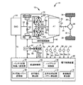
図1は、本発明が適用されるハイブリッド車両10(以下、車両10という)に備えられた動力伝達装置12の概略構成を説明する図であると共に、車両10における各種制御の為の制御機能及び制御系統の要部を説明する図である。図1において、車両10は、走行用駆動力源として機能するエンジン14及び電動機MGと、電動機MGによってエンジン14を始動するエンジン始動時に電動機MGへ電力を供給すると共に出力制限Woutからそのエンジン始動時に供給する電力分を差し引いた残りの電力の範囲内で電動機MGのみを走行用駆動力源として走行するモータ走行(EV走行)時に電動機MGへ電力を供給する蓄電装置16とを備えている。
FIG. 1 is a diagram illustrating a schematic configuration of a
動力伝達装置12は、非回転部材としてのトランスミッションケース18内において、エンジン14側から順番に、エンジン断接用クラッチK0(以下、クラッチK0という)、流体式伝動装置としてのトルクコンバータ20、及び自動変速機22等を備えている。又、動力伝達装置12は、自動変速機22の出力回転部材である変速機出力軸24に連結されたプロペラシャフト26、そのプロペラシャフト26に連結されたディファレンシャルギヤ28、そのディファレンシャルギヤ28に連結された1対の車軸30等を備えている。トルクコンバータ20のポンプ翼車20aは、クラッチK0を介してエンジン連結軸32と連結されていると共に、直接的に電動機MGと連結されている。トルクコンバータ20のタービン翼車20bは、自動変速機22の入力回転部材である変速機入力軸34と直接的に連結されている。ポンプ翼車20aには、エンジン14(及び/又は電動機MG)によって回転駆動されることにより、自動変速機22の変速制御やクラッチK0の係合解放制御などを実行する為の作動油圧を発生する機械式のオイルポンプ36が連結されている。このように構成された動力伝達装置12は、例えばFR型の車両10に好適に用いられる。動力伝達装置12において、エンジン14の動力(特に区別しない場合にはトルクや力も同義)は、クラッチK0が係合された場合に、エンジン14とクラッチK0とを連結するエンジン連結軸32から、クラッチK0、トルクコンバータ20、自動変速機22、プロペラシャフト26、ディファレンシャルギヤ28、及び1対の車軸30等を順次介して1対の駆動輪38へ伝達される。このように、動力伝達装置12は、エンジン14から駆動輪38までの動力伝達経路を構成する。
In the
自動変速機22は、トルクコンバータ20と駆動輪38との間の動力伝達経路に介在させられて、エンジン14及び電動機MGと駆動輪38との間の動力伝達経路の一部を構成し、走行用駆動力源(エンジン14及び電動機MG)からの動力を駆動輪38側へ伝達する変速機である。自動変速機22は、例えば変速比γ(=変速機入力軸回転速度Nin/変速機出力軸回転速度Nout)が異なる複数の変速段が選択的に成立させられる公知の遊星歯車式多段変速機、或いは変速比γが無段階に連続的に変化させられる公知の無段変速機などである。自動変速機22では、例えば油圧アクチュエータが油圧制御回路40によって制御されることにより、アクセル開度θaccや車速V等に応じて所定の変速比γが成立させられる。
The
電動機MGは、電気エネルギから機械的な動力を発生させる発動機としての機能及び機械的なエネルギーから電気エネルギを発生させる発電機としての機能を有する所謂モータジェネレータであり、インバータ42を介して蓄電装置16との間で電力が授受される。電動機MGは、エンジン14に替えて或いはエンジン14に加えて、インバータ42を介して蓄電装置16から供給される電力(特に区別しない場合には電気エネルギも同意)により走行用の動力を発生する。電動機MGは、エンジン14の動力や駆動輪38側から入力される被駆動力を回生により電気エネルギに変換し、その電気エネルギをインバータ42を介して蓄電装置16に蓄積する。電動機MGは、エンジン14と駆動輪38との間の動力伝達経路に設けられて、クラッチK0とトルクコンバータ20との間の動力伝達経路に連結されており、電動機MGとポンプ翼車20aとの間では、相互に動力が伝達される。又、電動機MGは、クラッチK0のスリップ乃至係合状態において、蓄電装置16からの電力供給を受けて作動させられることで、エンジン14をクランキングすることができる。
The electric motor MG is a so-called motor generator having a function as a motor that generates mechanical power from electric energy and a function as a generator that generates electric energy from mechanical energy. Electricity is exchanged with 16. The electric motor MG generates driving power using electric power supplied from the
クラッチK0は、例えば湿式多板型の油圧式摩擦係合装置であり、オイルポンプ36が発生する油圧を元圧とし油圧制御回路40によって係合解放制御される。その係合解放制御においては、例えば油圧制御回路40内のリニヤソレノイドバルブ等の調圧により、クラッチK0のトルク容量(以下、K0トルクという)が変化させられる。クラッチK0の係合状態では、エンジン連結軸32を介してポンプ翼車20aとエンジン14とが一体的に回転させられる。一方で、クラッチK0の解放状態では、エンジン14とポンプ翼車20aとの間の動力伝達が遮断される。すなわち、クラッチK0を解放することでエンジン14と駆動輪38とが切り離される。電動機MGはポンプ翼車20aに連結されているので、クラッチK0は、エンジン14と電動機MGとの間の動力伝達経路に設けられて、その動力伝達経路を断接するクラッチ、すなわち電動機MGをエンジン14と断接するクラッチとしても機能する。
The clutch K0 is, for example, a wet-type multi-plate hydraulic friction engagement device, and is engaged and released by the
車両10には、例えば電動機MGの作動などに関連する車両10の制御装置を含む電子制御装置60が備えられている。電子制御装置60は、例えばCPU、RAM、ROM、入出力インターフェース等を備えた所謂マイクロコンピュータを含んで構成されており、CPUはRAMの一時記憶機能を利用しつつ予めROMに記憶されたプログラムに従って信号処理を行うことにより車両10の各種制御を実行する。例えば、電子制御装置60は、エンジン14の出力制御、電動機MGの回生制御を含む電動機MGの駆動制御、自動変速機22の変速制御、クラッチK0のトルク容量制御等を実行するようになっており、必要に応じてエンジン制御用や電動機制御用や油圧制御用等に分けて構成される。電子制御装置60には、各種センサ(例えばエンジン回転速度センサ44、入力軸回転速度センサ46、出力軸回転速度センサ48、電動機回転速度センサ50、アクセル開度センサ52、加速度センサ54、バッテリセンサ56など)による検出値に基づく各種信号(例えばエンジン回転速度Ne、タービン回転速度Ntすなわち変速機入力軸回転速度Nin、車速Vに対応する変速機出力軸回転速度Nout、電動機回転速度(MG回転速度)Nm、運転者による車両10に対する駆動要求量に対応するアクセル開度θacc、車両加速度G、蓄電装置16の温度(バッテリ温度、電池温度)THbatや充電電流又は放電電流(バッテリ充放電電流、電池電流)Ibatや電圧(バッテリ電圧、電池電圧)Vbatなど)が、それぞれ供給される。電子制御装置60からは、例えばエンジン14の出力制御の為のエンジン出力制御指令信号Se、電動機MGの作動を制御する為の電動機制御指令信号Sm、クラッチK0や自動変速機22の油圧アクチュエータを制御する為に油圧制御回路40に含まれる電磁弁(ソレノイドバルブ)等を作動させる為の油圧制御指令信号Spなどが、スロットルアクチュエータや燃料噴射装置等のエンジン制御装置、インバータ42、油圧制御回路40などへそれぞれ出力される。
The
電子制御装置60は、車両10における各種制御の為の制御機能を実現する為に、蓄電装置出力設定手段として機能するバッテリ状態取得/設定手段すなわち蓄電装置出力設定部として機能するバッテリ状態取得/設定部62、変速制御手段すなわち変速制御部64、及びハイブリッド制御手段すなわちハイブリッド制御部66を備えている。
The
バッテリ状態取得/設定部62は、例えばバッテリ温度THbat、バッテリ充放電電流Ibat、及びバッテリ電圧Vbatに基づいて、蓄電装置16の充電容量(充電状態、充電レベル)SOCを算出する。バッテリ状態取得/設定部62は、例えば図2(a)に示すような入出力制限マップからバッテリ温度THbatに基づいて、蓄電装置16の入力制限(充電可能電力)Win及び出力制限(放電可能電力)Woutの基本値をそれぞれ設定する。そして、バッテリ状態取得/設定部62は、例えば図2(b)に示すような入出力制限用補正係数マップから充電容量SOCに基づいて入力制限用補正係数及び出力制限用補正係数をそれぞれ設定し、入力制限Win及び出力制限Woutの基本値に入力制限用補正係数及び出力制限用補正係数をそれぞれ乗算して、蓄電装置16の入力制限Win及び出力制限Woutをそれぞれ設定する。図2(a)に示す入出力制限マップは、バッテリ温度THbatと入出力制限Win/Woutとの予め実験的或いは設計的に求められて記憶された(すなわち予め定められた)関係の一例を示す図である。又、図2(b)に示す入出力制限用補正係数マップは、充電容量SOCと入出力制限Win/Woutの補正係数との予め定められた関係の一例を示す図である。
The battery state acquisition /
変速制御部64は、例えば車速Vと駆動要求量(例えばアクセル開度θacc等)とを変数として予め定められた公知の関係(変速線図、変速マップ;不図示)から車両状態(例えば実際の車速V及びアクセル開度θacc等)に基づいて、成立させるべき自動変速機22の変速比γを判断し、その判断した変速比γが得られる為の変速指令値を油圧制御回路40へ出力して、自動変速機22の自動変速制御を実行する。この変速指令値は、油圧制御指令信号Spの1つである。
The
ハイブリッド制御部66は、エンジン14の駆動を制御するエンジン駆動制御部としての機能と、インバータ42を介して電動機MGによる駆動力源又は発電機としての作動を制御する電動機作動制御部としての機能を含んでおり、それら制御機能によりエンジン14及び電動機MGによるハイブリッド駆動制御等を実行する。例えば、ハイブリッド制御部66は、アクセル開度θaccや車速Vに基づいて運転者による車両10に対する駆動要求量としての要求駆動トルクTdtgtを算出し、伝達損失、補機負荷、自動変速機22の変速比γ、蓄電装置16の入出力制限Win/Wout等を考慮して、その要求駆動トルクTdtgtが得られる走行用駆動力源(エンジン14及び電動機MG)の出力となるようにその走行用駆動力源を制御する指令信号(エンジン出力制御指令信号Se及び電動機制御指令信号Sm)を出力する。前記駆動要求量としては、駆動輪38における要求駆動トルクTdtgt[Nm]の他に、駆動輪38における要求駆動力[N]、駆動輪38における要求駆動パワー[W]、変速機出力軸24における要求変速機出力トルク等を用いることもできる。又、駆動要求量として、単にアクセル開度θacc[%]やスロットル弁開度[%]や吸入空気量[g/sec]等を用いることもできる。
The
具体的には、ハイブリッド制御部66は、例えば要求駆動トルクTdtgtが電動機MGの出力のみで賄える範囲の場合には、走行モードをモータ走行モード(EV走行モード)とし、クラッチK0を解放させた状態でEV走行を行う。一方で、ハイブリッド制御部66は、例えば要求駆動トルクTdtgtが少なくともエンジン14の出力を用いないと賄えない範囲の場合には、走行モードをエンジン走行モードすなわちハイブリッド走行モード(HV走行モード)とし、クラッチK0を係合させた状態で、少なくともエンジン14を走行用駆動力源として走行するエンジン走行すなわちハイブリッド走行(HV走行)を行う。他方で、ハイブリッド制御部66は、例えば要求駆動トルクTdtgtが電動機MGの出力のみで賄える範囲の場合であっても、エンジン14やエンジン14に関連する機器の暖機が必要な場合等には、HV走行を行う。このように、ハイブリッド制御部66は、要求駆動トルクTdtgt等に基づいて、エンジン走行中にエンジン14を自動停止したり、そのエンジン停止後にエンジン14を再始動したりして、EV走行とHV走行とを切り替える。例えば、ハイブリッド制御部66は、EV走行中に要求駆動トルクTdtgtに基づいてエンジン始動要求があるか否かを判断し、EV走行中に要求駆動トルクTdtgtが増大したことによってエンジン始動要求があると判断した場合には、エンジン14を始動してEV走行からHV走行へ切り替える。
Specifically, for example, when the required drive torque Tdtgt is within a range that can be covered only by the output of the electric motor MG, the
尚、電動機MGの出力は、電動機MG自身の定格出力に基づいて上限出力が規定されるものであるが、本実施例では、電動機MGの定格出力が蓄電装置16の定格出力よりも大きいので、蓄電装置16の充電が要求された場合などを含め、専ら、蓄電装置16の出力制限(放電可能電力)Woutに基づいて上限出力が規定される。つまり、ハイブリッド制御部66は、蓄電装置16の出力制限Woutに基づいて、要求駆動トルクTdtgtが電動機MGの出力のみで賄える範囲であるか否かを判断する。
Note that the output of the electric motor MG is an upper limit output based on the rated output of the electric motor MG itself, but in this embodiment, the rated output of the electric motor MG is larger than the rated output of the
ハイブリッド制御部66は、例えば解放されているクラッチK0を係合に向けて制御することで電動機MGによってエンジン14をクランキングしつつ、燃料供給やエンジン点火などを開始してエンジン14を始動する(特に区別しない場合は再始動することも同義とする)。この始動方法では、エンジン始動に必要なトルクであるエンジン始動トルクTstをエンジン14側へ伝達する為のK0トルクが得られるように、クラッチK0が制御される。このエンジン始動トルクTstは、クラッチK0を介してエンジン14側へ流れる分の電動機MGの出力トルク(以下、MGトルクTmという)に相当することから、その分だけ駆動輪38側へ流れる分のMGトルクTmが減少させられる。その為、この始動方法では、例えば駆動トルクTdの落ち込みを抑制する為に、要求駆動トルクTdtgtを満たす為に必要なMGトルクTmに加えて、エンジン始動トルクTstをエンジン14側へ伝達する為のK0トルクに相当するMGトルク分が増大される。見方を換えれば、EV走行中には、エンジン始動に備えて、エンジン始動トルクTst分を担保しておかなければならない。つまり、出力可能なMGトルクTmのうちでエンジン始動トルクTst分については、EV走行に用いないことが好ましい。このようなことから、本実施例のEV走行では、電動機MGが出力することができる最大のMGトルクTmに対して、エンジン始動に備えてエンジン始動トルクTst分を担保しておく分だけ、EV走行可能な領域(EV走行領域)が限定(縮小)される。従って、MGトルクTmのみで要求駆動トルクTdtgtを賄える範囲は、蓄電装置16の出力制限Woutにて出力可能な最大のMGトルクTmに対して、エンジン始動トルクTst分を除いたトルク領域となる。
The
上述したように、蓄電装置16の出力制限Woutに基づいてEV走行領域が規定される。一方で、エンジン始動はEV走行と比べて極めて短い所用時間であるので、エンジン始動トルクTstは短時間(例えば1秒以内)だけ発生させられれば良い。他方、蓄電装置16は短時間であれば定格出力よりも高い出力を発生することができる。従って、本実施例では、蓄電装置16の出力制限Woutを一時的に引き上げることで、EV走行領域の拡大を狙う。
As described above, the EV travel region is defined based on the output limit Wout of the
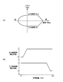
図3は、蓄電装置16の出力制限Woutを定格出力としたときと、それよりも一時的に引き上げたときとで、それぞれのEV走行領域を比較する一例の図である。図3における各線は、各々、出力(パワー)[W]を示している。出力制限Wout[W]に基づくEV走行領域を考える場合、便宜上、蓄電装置16の出力(以下、バッテリパワーPwという)を用いる。例えば、エンジン始動時に電動機MGが使用する電動機MGの出力(MGパワーPm)(すなわちそれに対応するバッテリパワーPw)であるエンジン始動パワーPst(エンジン始動トルクTst×MG回転速度Nmに対応)を蓄電装置16の出力制限Woutから差し引いた値にて設定される、EV走行できるMGパワーPmの上限値(すなわち電動機MGがEV走行に使用できるバッテリパワーPwの上限値)であるEV走行可能パワーPev(=Wout−Pst)を用いて、EV走行領域の広さを見る。
FIG. 3 is a diagram illustrating an example in which the EV travel regions are compared when the output limit Wout of the
図3において、太実線Aは、蓄電装置16の出力制限Woutを定格出力(通常バッテリ定格ともいう)としたときに電動機MGが出力可能な最大パワーを示している。又、太破線Bは、蓄電装置16の出力制限Woutを定格出力よりも所定出力ΔWout分増加させた一時アップ出力であるバッテリ1sec定格としたときに電動機MGが出力可能な最大パワーを示している。この太実線Aにおける定格出力に対応する出力制限Woutを定格出力制限Wout(0)とし、この太破線Bにおけるバッテリ1sec定格に対応する出力制限Woutを一時アップ出力制限Wout(up)(=Wout(0)+ΔWout)とする。細実線aは、蓄電装置16の出力制限Woutが定格出力制限Wout(0)であるときのEV走行可能パワーPevである第1上限出力としての定格制限時EV走行可能パワーPev1(=Wout(0)−Pst)を示している。又、細破線bは、蓄電装置16の出力制限Woutが一時アップ出力制限Wout(up)であるときのEV走行可能パワーPevである第2上限出力としての制限増大時EV走行可能パワーPev2(=Wout(up)−Pst)を示している。従って、定格制限時EV走行可能パワーPev1の範囲内の領域である通常EV走行領域Aが、蓄電装置16の出力制限Woutを定格出力としたときのEV走行領域である。又、制限増大時EV走行可能パワーPev2の範囲内の領域である一時アップ時EV走行領域Bが、蓄電装置16の出力制限Woutを定格出力よりも所定出力ΔWout分増加させたときのEV走行領域である。このように、出力制限Woutを定格出力よりも所定出力ΔWout分増加させることで、斜線部Cの分だけEV走行領域が拡大され、燃費が向上させられる。通常EV走行領域A内でエンジン始動要求(EV→HV要求)が為された場合は、蓄電装置16は定格出力制限Wout(0)内でエンジン始動分(エンジン始動パワーPst)を賄う為、電圧低下や耐久性劣化を抑制することができる。又、一時アップ時EV走行領域B内でエンジン始動要求が為された場合は、一時アップ分(ΔWout)で出力制限Woutを引き上げている為、EV走行領域を拡大している上に、エンジン14を始動することができる。
In FIG. 3, a thick solid line A indicates the maximum power that can be output by the electric motor MG when the output limit Wout of the
蓄電装置16の定格出力は、例えば蓄電装置16の諸元に基づいて、連続的に電力を出力しても耐久性上問題となり難い出力として予め定められた最大出力である。又、蓄電装置16のバッテリ1sec定格は例えば1秒程度であれば定格出力を超える電力を出力しても耐久性上許容できる出力として予め定められた最大出力である。従って、上記所定出力ΔWoutは、例えば定格出力を一時的に超えても耐久性上許容できる増加分の電力として予め定められた値である。又、例えば定格出力とした場合の定格出力制限Wout(0)及びバッテリ1sec定格とした場合の一時アップ出力制限Wout(up)を設定する為の図2に示すようなマップが各々予め定められている。そして、バッテリ状態取得/設定部62は、例えば各々に対応する図2に示すような各マップから定格出力制限Wout(0)及び一時アップ出力制限Wout(up)を設定する。
The rated output of the
ここで、本実施例では、単に、EV走行領域を拡大するのではなく、燃費向上の観点からEV定常走行可能領域を拡大することに主眼を置いて、蓄電装置16の出力制限Woutを定格出力よりも所定出力ΔWout分増加させる。これは、急加速が要求されたことに対応して、蓄電装置16の出力制限Woutを定格出力よりも所定出力ΔWout分増加させたとしても、エンジン始動が要求されるまでの時間が短く、EV走行を維持できる時間が短くされて(或いは車速Vが低くされて)、EV定常走行可能領域の拡大にそれほど寄与しない場合がある為である。これに対して、EV走行にて駆動要求量(例えばアクセル開度)が略一定とされたり車速Vが略一定とされるような定車速走行やアクセル開度が僅かに踏み増しされたり車速Vが緩やかに上昇されるような緩加速走行などの予め定められた定常走行において、車両10の走行抵抗(路面負荷)R/Lを緩やかに増減させる要因となる車速Vが所定以上である為に出力制限Woutを定格出力としたままでは走行抵抗R/Lに対応したMGパワーPmを出せずにEV走行できない車速域にある場合は、蓄電装置16の出力制限Woutを定格出力よりも所定出力ΔWout分増加させれば、EV定常走行可能領域の拡大に寄与すると考えられる。一方で、出力制限Woutを定格出力としたままでEV走行できる低車速域にある場合には、車速Vが低くなる程EV定常走行可能領域の拡大には寄与し難くなる。他方で、蓄電装置16の出力制限Woutを定格出力よりも所定出力ΔWout分増加させても、定常走行できないような高車速域にある場合には、EV定常走行可能領域の拡大には寄与しない。従って、本実施例では、所定車速以上においては、通常よりEV走行領域を拡大し、EV定常走行可能領域(例えばEV定常走行可能車速域)を拡大する。又、出力制限Woutを所定出力ΔWout分増加させなくてもEV走行が可能な領域では、敢えて所定出力ΔWout分増加しないことで、電圧低下や耐久性低下を回避する。又、出力制限Woutを所定出力ΔWout分増加させても定常走行できないような高車速では、所定出力ΔWout分増加してEV走行領域を拡大する必要はない為、所定出力ΔWout分増加によるEV走行領域の拡大を行わない。
Here, in the present embodiment, the output limit Wout of the
そこで、バッテリ状態取得/設定部62は、例えば車両10の走行抵抗R/Lが所定範囲にあるときは、蓄電装置16の出力制限Woutを、走行抵抗R/Lがその所定範囲よりも小さな値のときと比較して大きくし、且つ定格出力よりも所定出力ΔWout分増加させた値とする(すなわち出力制限Woutを定格出力制限Wout(0)よりも所定出力ΔWout分増加させた一時アップ出力制限Wout(up)とする)。又、バッテリ状態取得/設定部62は、例えば車両10の走行抵抗R/Lが所定範囲にあるときは、蓄電装置16の出力制限Woutを、走行抵抗R/Lがその所定範囲よりも大きな値のときと比較して大きくし、且つ定格出力よりも所定出力ΔWout分増加させた値とする。上記所定範囲は、例えばEV走行にて定常走行する為に必要なMGパワーPm(すなわちそれに対応するバッテリパワーPw)である定常走行必要パワーPwcが定格制限時EV走行可能パワーPev1を上回る車速範囲に車速Vがあるときの走行抵抗R/Lの範囲である。又、上記所定範囲は、例えば定常走行必要パワーPwcが制限増大時EV走行可能パワーPev2を下回る車速範囲に車速Vがあるときの走行抵抗R/Lの範囲である。
Therefore, when the running resistance R / L of the
具体的には、図1に戻り、電子制御装置60は、車両10における各種制御の為の制御機能を実現する為に、更に、モータ走行可能出力設定手段として機能するEV可能パワー設定手段すなわちモータ走行可能出力設定部として機能するEV可能パワー設定部68、走行抵抗算出手段すなわち走行抵抗算出部70、定常走行必要パワー算出手段すなわち定常走行必要パワー算出部72、及び車速範囲算出手段すなわち車速範囲算出部74を備えている。
Specifically, returning to FIG. 1, the
EV可能パワー設定部68は、蓄電装置16の出力制限Woutからエンジン始動パワーPstを差し引いた値であるEV走行可能パワーPevを設定する。具体的には、EV可能パワー設定部68は、バッテリ状態取得/設定部62により設定された定格出力制限Wout(0)と、エンジン始動パワーPstとに基づいて、定格制限時EV走行可能パワーPev1(=Wout(0)−Pst)を算出し、設定する。又、EV可能パワー設定部68は、バッテリ状態取得/設定部62により設定された一時アップ出力制限Wout(up)と、エンジン始動パワーPstとに基づいて、制限増大時EV走行可能パワーPev2(=Wout(up)−Pst)を算出し、設定する。上記エンジン始動パワーPstは、例えば予め定められた一律の値であるが、エンジン水温等に応じて変化するような予め定められた値などであっても良い。
EV possible
走行抵抗算出部70は、例えば車両10の走行抵抗R/Lを算出する。具体的には、走行抵抗R/Lは、例えば平坦路を定常走行する場合には、公知には、ころがり抵抗Frと空気抵抗Faとの合算値(=Fr+Fa)である。例えば、走行抵抗算出部70は、一般的な関係式(R/L=Fr+Fa:Fr=μ×Wg;μはころがり抵抗係数,Wgは車両重量(例えば推定重量)、Fa=(1/2)×ρ×A×Cd×V2;ρは空気密度,Aは前面投影面積,Cdは空気抵抗係数)から車速V及び推定重量Wgに基づいて走行抵抗R/Lを算出する。又は、走行抵抗算出部70は、予め定められたマップ等から車速V及び推定重量Wgに基づいて走行抵抗R/Lを算出しても良い。又、例えば推定重量Wgを略一定と見なせば、走行抵抗R/Lは、専ら車速Vに応じて変化させられるので、走行抵抗算出部70は、例えば車速Vに基づいて走行抵抗R/Lを算出しても良い。又、走行抵抗算出部70は、例えば坂路を走行する場合には、勾配抵抗Fsを更に加えて走行抵抗R/L(=Fr+Fa+Fs)を算出する。走行抵抗算出部70は、一般的な関係式(Fs=Wg×sinθ:θは路面勾配)から路面勾配θに基づいて勾配抵抗Fsを算出する。尚、一般的には、加速抵抗Facも走行抵抗R/Lとなるが、ここでは、定車速走行に対応する走行抵抗R/Lとして算出する為、加速抵抗Facは含めない。加速抵抗Fac分については、後述する、緩加速走行に対応する定常走行必要パワーPwcを算出する際の定常走行余裕分αに対応する走行抵抗分として取り扱う。
The traveling
定常走行必要パワー算出部72は、例えば走行抵抗算出部70により算出された車両10の走行抵抗R/Lに基づいて、定常走行必要パワーPwcを算出する。具体的には、定常走行必要パワー算出部72は、例えば走行抵抗R/Lに打ち勝って定車速走行を実現する為に必要なMGパワーPm(すなわちそれに対応するバッテリパワーPw)である定車速走行必要パワーPconを算出する。そして、定常走行必要パワー算出部72は、その定車速走行必要パワーPconに、安定して定常走行する上で必要なマージンとして予め定められた定常走行余裕分αを加算して定常走行必要パワーPwc(=Pcon+α)を算出する。このように、定常走行必要パワーPwcは走行抵抗R/Lに対応して(応じて)算出されるので、例えば図4に示すように、走行抵抗R/Lをパラメータとして車速Vを変数とする関数(特性)Pwc(=f(V,R/L))である。尚、定常走行余裕分αは、例えば車速Vに応じて緩やかに変化する走行抵抗R/Lに対応する定車速走行必要パワーPconと同程度の変化具合となるような緩加速走行を実現する為に定車速走行必要パワーPconに上乗せする必要があるMGパワーPm(すなわちそれに対応するバッテリパワーPw)である。
The steady travel required
車速範囲算出部74は、例えば定常走行必要パワーPwcが定格制限時EV走行可能パワーPev1を上回る車速範囲を走行抵抗R/Lの所定範囲として算出する。又、車速範囲算出部74は、例えば定常走行必要パワーPwcが制限増大時EV走行可能パワーPev2を下回る車速範囲を走行抵抗R/Lの所定範囲として算出する。具体的には、車速範囲算出部74は、図4に示すように、定常走行必要パワーPwcが定格制限時EV走行可能パワーPev1を上回る車速の下限値である一時アップ下限車速Vev1(すなわちPwcに基づいてPev1でEV走行可能な上限車速Vev1)を算出する。すなわち、車速範囲算出部74は、定常走行必要パワー算出部72により算出される定常走行必要パワー特性Pwc(=f(V,R/L))がEV可能パワー設定部68により設定される定格制限時EV走行可能パワーPev1となるときの車速Vを、走行抵抗R/Lの所定範囲に対応する前記車速範囲の下限車速である一時アップ下限車速Vev1として算出する。又、車速範囲算出部74は、図4に示すように、定常走行必要パワーPwcが制限増大時EV走行可能パワーPev2を下回る車速の上限値である一時アップ上限車速Vev2(すなわちPwcに基づいてPev2でEV走行可能な上限車速Vev2)を算出する。すなわち、車速範囲算出部74は、定常走行必要パワー算出部72により算出される定常走行必要パワー特性Pwc(=f(V,R/L))がEV可能パワー設定部68により設定される制限増大時EV走行可能パワーPev2となるときの車速Vを、走行抵抗R/Lの所定範囲に対応する前記車速範囲の上限車速である一時アップ上限車速Vev2として算出する。車速Vが一時アップ下限車速Vev1以上且つ一時アップ上限車速Vev2以下となる車速範囲が、蓄電装置16の出力制限Woutを定格出力よりも所定出力ΔWout分増加させた一時アップ出力制限Wout(up)とする一時アップ車速領域すなわち走行抵抗R/Lの所定範囲である。
The vehicle speed
バッテリ状態取得/設定部62は、車速範囲算出部74により算出された一時アップ車速領域に車速Vがあるか否かを判定する(すなわち走行抵抗R/Lが所定範囲にあるか否かを判定する)。バッテリ状態取得/設定部62は、車速Vが一時アップ車速領域にあるときは(すなわち走行抵抗R/Lが所定範囲にあるときは)、蓄電装置16の出力制限Woutを一時アップ出力制限Wout(up)に設定する。又、バッテリ状態取得/設定部62は、車速Vが一時アップ下限車速Vev1未満のときは(すなわち走行抵抗R/Lが所定範囲よりも小さな値のときは)、蓄電装置16の出力制限Woutを定格出力制限Wout(0)に設定する。又、バッテリ状態取得/設定部62は、車速Vが一時アップ上限車速Vev2を超えるときは(すなわち走行抵抗R/Lが所定範囲よりも大きな値のときは)、蓄電装置16の出力制限Woutを定格出力制限Wout(0)に設定する。これにより、本実施例では、図4に示すように、一時アップ車速領域(すなわち走行抵抗R/Lの所定範囲)にて蓄電装置16の出力制限Woutが引き上げられることで、EV定常走行可能領域(例えばEV定常走行可能車速域)が拡大される。この出力制限Woutの引き上げは、例えばアクセルがオンとされているパワーオン走行時に行うことが好適である。
The battery state acquisition /
図5は、電子制御装置60の制御作動の要部すなわち蓄電装置16の電圧低下と耐久性低下とを抑制することとEV定常走行可能領域を拡大することとを両立する為の制御作動を説明するフローチャートであり、例えば数msec乃至数十msec程度の極めて短いサイクルタイムで繰り返し実行される。
FIG. 5 illustrates a control operation for controlling the main part of the control operation of the
図5において、先ず、走行抵抗算出部70に対応するステップ(以下、ステップを省略する)S1において、例えば車速V、推定重量Wg、及び路面勾配θ(坂路走行時のみ、或いは平坦路走行時はθを零とする)に基づいて車両10の走行抵抗R/Lが算出される。次いで、定常走行必要パワー算出部72に対応するS2において、例えば上記S1にて算出された走行抵抗R/Lに基づいて定常走行必要パワー特性Pwcが算出される。次いで、EV可能パワー設定部68に対応するS3において、例えば定格制限時EV走行可能パワーPev1と制限増大時EV走行可能パワーPev2とが算出される。次いで、車速範囲算出部74に対応するS4において、例えば上記S2にて算出された定常走行必要パワー特性Pwcに基づいて、上記S3にて算出された定格制限時EV走行可能パワーPev1でEV走行可能な上限車速(一時アップ下限車速)Vev1、及び上記S3にて算出された制限増大時EV走行可能パワーPev2でEV走行可能な上限車速(一時アップ上限車速)Vev2が算出される。つまり、このS4では走行抵抗R/Lに応じて、蓄電装置16の出力制限Woutを一時的に引き上げる一時アップ領域が設定される。次いで、バッテリ状態取得/設定部62に対応するS5において、例えば上記S4にて設定された一時アップ領域(Vev1≦V≦Vev2)にあるか否か、すなわち上記S4にて算出された一時アップ車速領域(一時アップ下限車速Vev1以上且つ一時アップ上限車速Vev2以下となる車速範囲)に車速Vがあるか否かが判定される。このS5の判断が肯定される場合はバッテリ状態取得/設定部62に対応するS6において、例えば蓄電装置16の出力制限Woutが一時アップ出力制限Wout(up)に設定される。これにより、EV走行領域が拡大される。上記S5の判断が否定される場合はバッテリ状態取得/設定部62に対応するS7において、例えば蓄電装置16の出力制限Woutが一時アップ出力制限Wout(up)とされず、定格出力制限Wout(0)に設定される。これにより、EV走行領域が拡大されない。上記S6又はS7に次いで、ハイブリッド制御部66に対応するS8において、例えばエンジン始動要求があるか否かが判断される。このS8の判断が肯定される場合はハイブリッド制御部66に対応するS9において、例えばクラッチK0が係合に向けて制御され、電動機MGによってエンジン14がクランキングされてエンジン14が始動される。これにより、EV走行からHV走行へ移行される。上記S8の判断が否定される場合はハイブリッド制御部66に対応するS10において、例えばEV走行が継続される。
In FIG. 5, first, in a step (hereinafter, step is omitted) S1 corresponding to the traveling
上述のように、本実施例によれば、車速Vに応じて(すなわち走行抵抗R/Lに応じて)蓄電装置16の出力制限Woutを増加させる範囲を限定することで、蓄電装置16の電圧低下と耐久性低下とを抑制することと、EV定常走行可能領域を拡大することとを両立することができる。具体的には、車速Vが低車速域にあることで走行抵抗R/Lが比較的小さいときは、蓄電装置16の出力制限Woutが定格出力とされるので、例えば急なエンジン始動要求に対しても蓄電装置16は定格出力以上の超過出力を行わなくて、蓄電装置16の耐久性劣化や電圧低下を抑制することができる。又、車速Vが上記低車速域よりも高車速域にあることで走行抵抗R/Lが比較的大きいときは、蓄電装置16の出力制限Woutが増加させられるので、EV定常走行可能領域を拡大することができる。
As described above, according to the present embodiment, the voltage of the
以上、本発明の実施例を図面に基づいて詳細に説明したが、本発明はその他の態様においても適用される。 As mentioned above, although the Example of this invention was described in detail based on drawing, this invention is applied also in another aspect.
例えば、前述の実施例では、電動機MGは走行用駆動力源として機能し且つエンジン14の始動にも用いられたが、必ずしもこの態様に限らない。例えば、走行用駆動力源として機能する電動機とエンジン始動用の電動機とを別々に備える車両10であっても良い。要は、EV走行時に電動機へ電力を供給すると共にエンジン始動時に電動機へ電力を供給する蓄電装置16、すなわちエンジン始動用の電力分を担保した残りの電力にてモータ走行用の電力が設定される蓄電装置16を備える車両10であれば良く、電動機は種々の態様が採用され得る。従って、本発明が適用される車両は、前述の実施例にて示したような、エンジン14とクラッチK0と電動機MGと蓄電装置16とを備える車両10に限定されるものではなく、本発明は、エンジンと電動機と上述したような蓄電装置16とを備える車両であれば適用され得る。
For example, in the above-described embodiment, the electric motor MG functions as a driving force source for traveling and is also used for starting the
また、前述の実施例では、走行抵抗R/Lが前記所定範囲よりも小さな値のときは、蓄電装置16の出力制限Woutを定格出力のままとしたが、これに限らない。例えば、走行抵抗R/Lが前記所定範囲よりも小さな値のときは、蓄電装置16の出力制限Woutを、走行抵抗R/Lがその所定範囲にあるときと比較して小さな値とする範囲で、定格出力よりも大きな値としても良い。このようにすれば、走行抵抗R/Lが前記所定範囲よりも小さな値のときは、走行抵抗R/Lがその所定範囲にあるときと比較して、蓄電装置16の出力制限Woutが小さな値とされるので、例えば急なエンジン始動要求に対しても蓄電装置16は超過出力を抑制する(すなわち蓄電装置16の出力制限Woutが定格出力よりも所定出力ΔWout分ほどは増加させられない)。よって、蓄電装置16の耐久性劣化や電圧低下を抑制することができるという一定の効果が得られる。
In the above-described embodiment, when the running resistance R / L is a value smaller than the predetermined range, the output limit Wout of the
また、前述の実施例では、走行抵抗R/Lが前記所定範囲よりも大きな値のときは、蓄電装置16の出力制限Woutを定格出力のままとしたが、これに限らない。例えば、走行抵抗R/Lが前記所定範囲よりも大きな値のときは、蓄電装置16の出力制限Woutを、走行抵抗R/Lがその所定範囲にあるときと比較して小さな値とする範囲で、定格出力よりも大きな値としても良い。このようにすれば、走行抵抗R/Lが前記所定範囲よりも大きな値のときは、走行抵抗R/Lがその所定範囲にあるときと比較して、蓄電装置16の出力制限Woutが小さな値とされるので、例えば急なエンジン始動要求に対しても蓄電装置16は超過出力を抑制する(すなわち蓄電装置16の出力制限Woutが定格出力よりも所定出力ΔWout分ほどは増加させられない)。よって、蓄電装置16の耐久性劣化や電圧低下を抑制することができるという一定の効果が得られる。
In the above-described embodiment, when the running resistance R / L is a value larger than the predetermined range, the output limit Wout of the
また、前述の実施例は、EV定常走行可能領域を拡大するものであり、例えば急加速等が要求されたときにEV走行を継続できるようにするものではない。その為、走行抵抗R/Lが所定範囲にあるとき(車速Vが一時アップ車速領域(Vev1乃至Vev2)にあるとき)においてアクセル急踏み増しによる急なエンジン始動が為されたときには、EV走行の継続にあまり寄与できるものではなく、速やかにエンジン14が始動されてHV走行へ切り替えられる。但し、一旦HV走行へ切り替えられたとしても、走行抵抗R/Lが所定範囲にあるときに再び定常走行とされると、再びEV走行へ切り替えられる。
Further, the above-described embodiment expands the EV steady travel possible region, and does not allow the EV travel to be continued when, for example, sudden acceleration is required. Therefore, when the engine resistance is suddenly increased when the running resistance R / L is in the predetermined range (when the vehicle speed V is in the temporarily up vehicle speed range (Vev1 to Vev2)) and the accelerator suddenly increases, It does not contribute much to continuation, and the
また、前述の実施例では、走行抵抗R/Lを算出し、その走行抵抗R/Lに基づいて定常走行必要パワー特性Pwcを算出したが、この態様に限らない。例えば、路面勾配θや推定重量Wgをパラメータとして車速Vを変数とする予め定められた定常走行必要パワー特性Pwcを有する態様としても良い。このような態様であれば、走行抵抗R/Lや定常走行必要パワー特性Pwcを算出する必要が無くなる。このような態様を採用する場合、例えば図5に示すフローチャートにおいて、S1やS2を備える必要はない。又、走行抵抗R/Lの所定範囲に対応する、蓄電装置16の出力制限Woutを一時的に引き上げる一時アップ領域として、一時アップ車速領域(Vev1乃至Vev2)を設定したが、この態様に限らない。例えば、定常走行必要パワーPwcが定格制限時EV走行可能パワーPev1以上且つ制限増大時EV走行可能パワーPev2以下となる範囲を一時アップ領域(すなわち走行抵抗R/Lの所定範囲)として設定しても良い。このような態様を採用する場合、例えば図5に示すフローチャートにおいて、S4を備える必要はなく、又、S5においては一時アップ領域(Pev1≦Pwc≦Pev2)にあるか否かが判断される。このように、図5のフローチャートにおいて各ステップの実行内容やその実行順等は差し支えのない範囲で適宜変更することができる。
In the above-described embodiment, the running resistance R / L is calculated, and the steady running required power characteristic Pwc is calculated based on the running resistance R / L. However, the present invention is not limited to this mode. For example, it may be possible to have a predetermined steady running required power characteristic Pwc having the vehicle speed V as a variable with the road surface gradient θ and the estimated weight Wg as parameters. With such an aspect, it is not necessary to calculate the running resistance R / L and the steady running required power characteristic Pwc. When such an aspect is adopted, for example, in the flowchart shown in FIG. 5, it is not necessary to include S1 and S2. In addition, the temporary up vehicle speed region (Vev1 to Vev2) is set as the temporary up region for temporarily raising the output limit Wout of the
また、前述の実施例において、車両10には、自動変速機22が設けられていたが、この自動変速機22は必ずしも設けられなくても良い。但し、車両10が自動変速機22を備えることで、以下に例示する制御態様を実行することが可能である。例えば、MGトルクTmの上限値は、インバータ42の諸元に基づいて決定(設定)される場合がある。このような場合、蓄電装置16の出力制限Woutを増加させてもMGトルクTmの上限値が増大しないことがある。このようにMGトルクTmの上限値が増大しない場合は、自動変速機22の変速比を低車速側の変速比(ロー側変速比)とすることで、MGパワーPmを増やしてもMGトルクTmの上限値が増大しない領域において蓄電装置16の出力制限Woutを増加させても良い。上記自動変速機22の変速比をロー側変速比とすることとは、例えば蓄電装置16の出力制限Woutを増加させない場合は自動変速機22のアップシフトを行う車速域においても、そのアップシフトを行わずにロー側変速比を維持すること、或いは蓄電装置16の出力制限Woutを増加させない場合に対してコーストダウン判断車速を高くすることである。
In the above-described embodiment, the
また、前述の実施例では、流体式伝動装置としてトルクコンバータ20が用いられていたが、トルク増幅作用のない流体継手などの他の流体式伝動装置が用いられても良い。又、トルクコンバータ20は必ずしも設けられなくても良い。
In the above-described embodiment, the
尚、上述したのはあくまでも一実施形態であり、本発明は当業者の知識に基づいて種々の変更、改良を加えた態様で実施することができる。 The above description is only an embodiment, and the present invention can be implemented in variously modified and improved forms based on the knowledge of those skilled in the art.
10:ハイブリッド車両
14:エンジン
16:蓄電装置
60:電子制御装置(制御装置)
62:バッテリ状態取得/設定部(蓄電装置出力設定部)
MG:電動機
10: Hybrid vehicle 14: Engine 16: Power storage device 60: Electronic control device (control device)
62: Battery state acquisition / setting unit (power storage device output setting unit)
MG: Electric motor
Claims (1)
前記ハイブリッド車両の、車速に応じて変化させられる走行抵抗が所定範囲にあるときは、前記蓄電装置の出力制限を、該走行抵抗が該所定範囲よりも小さな値のときと比較して大きくし、且つ定格出力よりも所定出力分増加させた値とする蓄電装置出力設定部を含み、
前記蓄電装置の出力制限が定格出力であるときに前記電動機がモータ走行に使用できる前記蓄電装置の出力の上限値である第1上限出力を、前記蓄電装置の出力制限から前記エンジン始動時に前記電動機が使用する前記蓄電装置の出力を差し引いた値にて設定し、
前記モータ走行にて定常走行する為に必要な前記蓄電装置の出力である前記車速に基づいた定常走行必要パワーが前記第1上限出力を上回る車速範囲を前記走行抵抗の所定範囲とすること、又は、前記定常走行必要パワーが前記第1上限出力以上、且つ前記蓄電装置の出力制限が定格出力よりも所定出力分増加させられているときに前記電動機がモータ走行に使用できる前記蓄電装置の出力の上限値である第2上限出力以下となる範囲を前記走行抵抗の所定範囲とすることを特徴とするハイブリッド車両の制御装置。 An engine, an electric motor, and the electric motor for starting the engine are supplied with electric power to the electric motor at the time of starting the engine, and only the electric motor is within the remaining electric power range obtained by subtracting the electric power supplied at the time of starting the engine from the output restriction. A control device of a hybrid vehicle comprising a power storage device that supplies electric power to the electric motor during traveling of a motor that travels as a driving power source for traveling,
When the traveling resistance of the hybrid vehicle that is changed according to the vehicle speed is within a predetermined range, the output limit of the power storage device is increased compared to when the traveling resistance is a value smaller than the predetermined range, And including a power storage device output setting unit having a value increased by a predetermined output from the rated output,
When the output limit of the power storage device is a rated output, a first upper limit output that is an upper limit value of the output of the power storage device that can be used for motor running by the electric motor is changed from the output limit of the power storage device to the time of starting the engine. Set by subtracting the output of the power storage device used by
Be the electric storage device predetermined range of the vehicle speed range the running resistance steady running required power based on the vehicle speed is output is above said first upper limit output necessary to steady running at the motor running, or When the power required for steady running is equal to or higher than the first upper limit output and the output limit of the power storage device is increased by a predetermined output from the rated output, the output of the power storage device that can be used for motor travel by the motor A hybrid vehicle control apparatus characterized in that a range that is equal to or lower than a second upper limit output that is an upper limit value is set as a predetermined range of the running resistance.
Priority Applications (1)
| Application Number | Priority Date | Filing Date | Title |
|---|---|---|---|
| JP2013185491A JP6201546B2 (en) | 2013-09-06 | 2013-09-06 | Control device for hybrid vehicle |
Applications Claiming Priority (1)
| Application Number | Priority Date | Filing Date | Title |
|---|---|---|---|
| JP2013185491A JP6201546B2 (en) | 2013-09-06 | 2013-09-06 | Control device for hybrid vehicle |
Publications (2)
| Publication Number | Publication Date |
|---|---|
| JP2015051707A JP2015051707A (en) | 2015-03-19 |
| JP6201546B2 true JP6201546B2 (en) | 2017-09-27 |
Family
ID=52701080
Family Applications (1)
| Application Number | Title | Priority Date | Filing Date |
|---|---|---|---|
| JP2013185491A Active JP6201546B2 (en) | 2013-09-06 | 2013-09-06 | Control device for hybrid vehicle |
Country Status (1)
| Country | Link |
|---|---|
| JP (1) | JP6201546B2 (en) |
Families Citing this family (2)
| Publication number | Priority date | Publication date | Assignee | Title |
|---|---|---|---|---|
| JP7147155B2 (en) | 2017-11-27 | 2022-10-05 | トヨタ自動車株式会社 | hybrid car |
| JP7322765B2 (en) * | 2020-03-17 | 2023-08-08 | トヨタ自動車株式会社 | vehicle controller |
Family Cites Families (5)
| Publication number | Priority date | Publication date | Assignee | Title |
|---|---|---|---|---|
| JP4207829B2 (en) * | 2003-07-02 | 2009-01-14 | トヨタ自動車株式会社 | Output management device and electric vehicle equipped with the same |
| JP4687476B2 (en) * | 2005-03-15 | 2011-05-25 | トヨタ自動車株式会社 | Power output device, automobile equipped with the same, hybrid vehicle, and control method for power output device |
| JP5659691B2 (en) * | 2010-10-22 | 2015-01-28 | 日産自動車株式会社 | Control device for hybrid vehicle and control method for hybrid vehicle |
| WO2012140762A1 (en) * | 2011-04-14 | 2012-10-18 | トヨタ自動車株式会社 | Hybrid vehicle and output control method for electric power storage device installed therein |
| JP2013086704A (en) * | 2011-10-20 | 2013-05-13 | Toyota Motor Corp | Hybrid vehicle and control method of the same |
-
2013
- 2013-09-06 JP JP2013185491A patent/JP6201546B2/en active Active
Also Published As
| Publication number | Publication date |
|---|---|
| JP2015051707A (en) | 2015-03-19 |
Similar Documents
| Publication | Publication Date | Title |
|---|---|---|
| US9085291B2 (en) | Control system for vehicle | |
| US10232698B2 (en) | Mode transition control device for hybrid vehicle | |
| EP2018305B1 (en) | Driving system for hybrid vehicle | |
| JP5633641B2 (en) | Vehicle control device | |
| JP5962665B2 (en) | Control device for hybrid vehicle | |
| JP5884894B2 (en) | Vehicle control device | |
| JP5772979B2 (en) | Control device for hybrid vehicle | |
| JP2013071551A (en) | Control apparatus of hybrid vehicle | |
| US9656664B2 (en) | Hybrid vehicle control device | |
| US20140296027A1 (en) | Control apparatus for vehicle | |
| JP6540679B2 (en) | Transmission control device for hybrid vehicle | |
| JP2014208502A (en) | Controller for vehicle | |
| US20190276001A1 (en) | Hybrid vehicle engine start/stop system | |
| JP4258513B2 (en) | Control device for driving device | |
| JP5794377B2 (en) | Vehicle control device | |
| US11535254B2 (en) | Hybrid/electric vehicle control system | |
| JP2021146816A (en) | Control device of vehicle | |
| JP6201546B2 (en) | Control device for hybrid vehicle | |
| JP2022063156A (en) | Vehicle control device | |
| US20220194354A1 (en) | Method of supervisory control for power management of a parallel two motor hybrid powertrain | |
| JP7283039B2 (en) | hybrid vehicle | |
| CN114379377B (en) | Control device for vehicle | |
| US11524675B2 (en) | Vehicle and method of warning a vehicle operator of an impending shutdown of an electrical outlet on the vehicle | |
| JP3747941B2 (en) | Vehicle control apparatus having a plurality of prime movers | |
| JP2022179138A (en) | Control device of vehicle |
Legal Events
| Date | Code | Title | Description |
|---|---|---|---|
| A621 | Written request for application examination |
Free format text: JAPANESE INTERMEDIATE CODE: A621 Effective date: 20151005 |
|
| A977 | Report on retrieval |
Free format text: JAPANESE INTERMEDIATE CODE: A971007 Effective date: 20160608 |
|
| A131 | Notification of reasons for refusal |
Free format text: JAPANESE INTERMEDIATE CODE: A131 Effective date: 20160621 |
|
| A521 | Written amendment |
Free format text: JAPANESE INTERMEDIATE CODE: A523 Effective date: 20160805 |
|
| A131 | Notification of reasons for refusal |
Free format text: JAPANESE INTERMEDIATE CODE: A131 Effective date: 20170131 |
|
| A521 | Written amendment |
Free format text: JAPANESE INTERMEDIATE CODE: A523 Effective date: 20170309 |
|
| TRDD | Decision of grant or rejection written | ||
| A01 | Written decision to grant a patent or to grant a registration (utility model) |
Free format text: JAPANESE INTERMEDIATE CODE: A01 Effective date: 20170801 |
|
| A61 | First payment of annual fees (during grant procedure) |
Free format text: JAPANESE INTERMEDIATE CODE: A61 Effective date: 20170814 |
|
| R151 | Written notification of patent or utility model registration |
Ref document number: 6201546 Country of ref document: JP Free format text: JAPANESE INTERMEDIATE CODE: R151 |