JP6192483B2 - Information processing program, information processing apparatus, information processing system, and information processing method - Google Patents
Information processing program, information processing apparatus, information processing system, and information processing method Download PDFInfo
- Publication number
- JP6192483B2 JP6192483B2 JP2013217534A JP2013217534A JP6192483B2 JP 6192483 B2 JP6192483 B2 JP 6192483B2 JP 2013217534 A JP2013217534 A JP 2013217534A JP 2013217534 A JP2013217534 A JP 2013217534A JP 6192483 B2 JP6192483 B2 JP 6192483B2
- Authority
- JP
- Japan
- Prior art keywords
- virtual object
- marker
- image
- captured image
- information processing
- Prior art date
- Legal status (The legal status is an assumption and is not a legal conclusion. Google has not performed a legal analysis and makes no representation as to the accuracy of the status listed.)
- Active
Links
Images


Classifications
-
- H—ELECTRICITY
- H04—ELECTRIC COMMUNICATION TECHNIQUE
- H04N—PICTORIAL COMMUNICATION, e.g. TELEVISION
- H04N5/00—Details of television systems
- H04N5/222—Studio circuitry; Studio devices; Studio equipment
- H04N5/262—Studio circuits, e.g. for mixing, switching-over, change of character of image, other special effects ; Cameras specially adapted for the electronic generation of special effects
- H04N5/265—Mixing
-
- G—PHYSICS
- G06—COMPUTING; CALCULATING OR COUNTING
- G06T—IMAGE DATA PROCESSING OR GENERATION, IN GENERAL
- G06T19/00—Manipulating 3D models or images for computer graphics
- G06T19/006—Mixed reality
-
- H—ELECTRICITY
- H04—ELECTRIC COMMUNICATION TECHNIQUE
- H04N—PICTORIAL COMMUNICATION, e.g. TELEVISION
- H04N5/00—Details of television systems
- H04N5/222—Studio circuitry; Studio devices; Studio equipment
- H04N5/2224—Studio circuitry; Studio devices; Studio equipment related to virtual studio applications
Description
本発明は、現実空間に各種情報を重畳する情報処理プログラム、情報処理装置、情報処理システム、および、情報処理方法に関する。 The present invention relates to an information processing program, an information processing apparatus, an information processing system, and an information processing method for superimposing various types of information on a real space.
現実空間に各種情報を重畳して提示することによって、現実世界を拡張することを拡張現実(AR:Augmented Reality)という。ARの技術の一つとして、AR用のマーカ、
例えば、カードに印刷された2次元バーコードを用いる技術がある。この技術では、カメラの撮像画像からAR用のマーカとして2次元バーコードが識別され、該マーカに対応付けられた3次元画像データが2次元バーコードの位置に重畳して表示装置に表示される。
Augmented Reality (AR) refers to extending the real world by superimposing and presenting various information in the real space. As one of AR technologies, AR markers,
For example, there is a technique that uses a two-dimensional barcode printed on a card. In this technique, a two-dimensional barcode is identified as an AR marker from a captured image of a camera, and three-dimensional image data associated with the marker is superimposed on the position of the two-dimensional barcode and displayed on a display device. .
しかしながら、該拡張現実技術では、表示装置の撮像画像を表示する画面において、マーカの位置に、該マーカに対応する3次元画像データが重畳して表示されるだけであって、視覚的効果として、変化が乏しいものであった。 However, in the augmented reality technology, on the screen displaying the captured image of the display device, only the three-dimensional image data corresponding to the marker is superimposed and displayed at the position of the marker. Change was poor.
本発明は、上記した問題に鑑み、視覚的な変化に富んだ拡張現実技術を提供することを課題とする。 In view of the above problems, an object of the present invention is to provide augmented reality technology rich in visual changes.
本発明では、上記課題を解決するために、以下の構成を採用した。即ち、本発明は、コンピュータを、現実空間の撮像画像を取得する画像取得手段と、該撮像画像から特徴を検出する特徴検出手段と、該撮像画像の撮像手段の状況に応じて変化させて、仮想オブジェクト又は仮想オブジェクトと該仮想オブジェクトの態様と、を決定する決定手段と、決定された仮想オブジェクト又は決定された態様の仮想オブジェクトが特徴に基づいて配置された仮想空間の画像を生成する画像生成手段と、仮想空間の画像が現実空間に重畳されてユーザから視認されるように、表示装置に画像を表示させる表示制御手段と、
として機能させる情報処理プログラムである。
In the present invention, the following configuration is adopted in order to solve the above problems. That is, the present invention changes the computer according to the situation of the image acquisition means for acquiring the captured image of the real space, the feature detection means for detecting the feature from the captured image, and the imaging means of the captured image, Determination means for determining a virtual object or a virtual object and an aspect of the virtual object, and image generation for generating an image of a virtual space in which the determined virtual object or the virtual object of the determined aspect is arranged based on a feature Means, and display control means for displaying the image on the display device so that the image in the virtual space is superimposed on the real space and visually recognized by the user,
Is an information processing program to function as.
ここで、表示装置は、本発明に係る情報処理装置に周辺機器として接続されたものであってもよいし、通信網等を介して接続されたものであってもよい。また、本発明に係る情報処理装置は、所謂クラウド等の仮想的な環境に構築されたものであってもよい。 Here, the display device may be connected to the information processing apparatus according to the present invention as a peripheral device, or may be connected via a communication network or the like. The information processing apparatus according to the present invention may be constructed in a virtual environment such as a so-called cloud.
また、現実空間に配置された特徴とは、例えば、所謂AR用のマーカ、または二次元バーコード等のコードである。そして、このような特徴は、例えばカード等の部品に付されてよい。また、このような特徴は、専用のマーカやコード等に限られない。他用途に用いられる物品であっても、仮想オブジェクトの表示基準を取得可能なものであれば、前記特徴として用いることが出来る。 The feature arranged in the real space is, for example, a so-called AR marker or a code such as a two-dimensional barcode. And such a feature may be given to components, such as a card, for example. Moreover, such a feature is not limited to a dedicated marker or code. An article used for other purposes can be used as the feature as long as it can acquire a display reference of a virtual object.
本発明によれば、特徴の認識手段の状況に応じて、該特徴に基づいて表示される仮想オブジェクト又は仮想オブジェクトの態様の少なくとも一方が変化するので、視覚的な変化
に富んだ拡張現実技術を提供することができる。
According to the present invention, according to the situation of the feature recognition means, at least one of the virtual object displayed based on the feature or the aspect of the virtual object changes. Can be provided.
なお、本発明が適用される拡張現実技術の種類は限定されない。本発明は、例えば、撮像画像に仮想空間画像を合成した合成画像を表示することで仮想空間の画像が現実空間に重畳されてユーザから視認されるタイプの拡張現実技術にも適用可能であるし、ユーザの視界に仮想空間画像を映写することで仮想空間の画像が現実空間に重畳されてユーザから視認されるタイプの拡張現実技術(例えば、HUD:Head-Up Display等)にも適用可能
である。
The type of augmented reality technology to which the present invention is applied is not limited. The present invention is also applicable to, for example, an augmented reality technology in which a virtual image is superimposed on a real space and displayed by a user by displaying a composite image obtained by synthesizing the virtual space image with the captured image. It can also be applied to augmented reality technology (for example, HUD: Head-Up Display, etc.) in which a virtual space image is projected on the user's field of view so that the virtual space image is superimposed on the real space and viewed by the user. is there.
また、コンピュータは、撮像手段として、同一の筐体に複数のカメラを備え、決定手段は、撮像画像の撮像手段の状況として、撮像画像が複数のカメラのいずれによって撮像されたかに応じて、仮想オブジェクト又は仮想オブジェクトと該仮想オブジェクトの態様とを決定するようにしてもよい。 In addition, the computer includes a plurality of cameras in the same housing as the imaging unit, and the determination unit determines whether the captured image is captured by a plurality of cameras as the status of the imaging unit of the captured image. You may make it determine an object or a virtual object, and the aspect of this virtual object.
これによって、撮像画像がいずれのカメラで撮像されたかによって、特徴に基づいて仮想空間に配置される仮想オブジェクト又は仮想オブジェクトと該仮想オブジェクトの態様とが変化するようになり、視覚的な変化に富んだ拡張現実技術を提供することができる。 As a result, the virtual object or virtual object arranged in the virtual space and the aspect of the virtual object change according to the feature depending on which camera the captured image is captured, and the visual change is rich. Can provide augmented reality technology.
また、コンピュータは、表示装置を同一の筐体に備え、複数のカメラの一部は、表示装置の表示画面と略同一の面に備えられ、複数のカメラの他の一部は、表示装置の表示画面と略同一の面以外の面に備えられ、決定手段は、撮像画像の撮像手段の状況として、該撮像画像が、表示画面と略同一の面に備えられているカメラによる撮像画像であるか、表示画面と略同一の面以外の面に備えられているカメラによる撮像画像であるかによって、仮想オブジェクト又は仮想オブジェクトと該仮想オブジェクトの態様とを決定するようにしてもよい。また、複数のカメラの前記一部と、前記他の一部とは、コンピュータの姿勢を基準にした撮像方向が略逆方向であってもよい。 In addition, the computer includes a display device in the same housing, a part of the plurality of cameras is provided on substantially the same surface as the display screen of the display device, and the other part of the plurality of cameras is a part of the display device. Provided on a surface other than the substantially same surface as the display screen, and the determining means is a captured image obtained by a camera provided on the substantially same surface as the display screen as the state of the captured image capturing means. Alternatively, the virtual object or the virtual object and the mode of the virtual object may be determined depending on whether the image is captured by a camera provided on a surface other than the substantially same surface as the display screen. Further, the imaging direction based on the posture of the computer may be substantially opposite to the part of the plurality of cameras and the other part.
これによって、表示装置の表示面と略同一の面に配置されたカメラで特徴を撮像した場合に、他の面に配置されたカメラで同じ特徴を撮像した場合とは異なる仮想オブジェクト又は仮想オブジェクトの態様が表示さるので、ユーザに驚きを与えることができ、拡張現実技術の娯楽性を高めることができる。 As a result, when a feature is imaged with a camera arranged on a surface substantially the same as the display surface of the display device, a virtual object or virtual object that is different from a case where the same feature is imaged with a camera arranged on another surface is used. Since the aspect is displayed, the user can be surprised and the amusement of augmented reality technology can be enhanced.
また、決定手段は、撮像画像の撮像手段の状況として、撮像画像の撮像手段の変化に応じて、仮想オブジェクト又は仮想オブジェクトと該仮想オブジェクトの態様とを変化させるようにしてもよい。これによって、撮像手段が切り替わる度に特徴に基づいて表示される仮想オブジェクト又は仮想オブジェクトの態様が変化するので、拡張現実技術の娯楽性を高めることができる。 Further, the determining unit may change the virtual object or the virtual object and the mode of the virtual object according to the change of the imaging unit of the captured image as the situation of the imaging unit of the captured image. Thereby, since the aspect of the virtual object or virtual object displayed based on the characteristics changes every time the imaging unit is switched, the amusement of augmented reality technology can be enhanced.
また、仮想オブジェクトの態様は、該仮想オブジェクトの外観で定義されてもよい。また、仮想オブジェクトの態様は、該仮想オブジェクトの姿勢で定義されてもよい。また、仮想オブジェクトの態様は、該仮想オブジェクトに実行させる動作で定義されてもよい。これによって、仮想オブジェクトの態様の変化を富んだものにすることができる。 Also, aspects of the virtual object may be defined by the appearance of the virtual object. Also, aspects of the virtual object may be defined by the attitude of the virtual object. In addition, the mode of the virtual object may be defined by an operation that is executed by the virtual object. Thereby, it is possible to enrich the change in the aspect of the virtual object.
また、本発明は、情報処理装置、1または複数の情報処理装置を有する情報処理システム、コンピュータによって実行される方法、またはコンピュータに実行させるプログラムとしても把握することが可能である。また、本発明は、そのようなプログラムをコンピュータその他の装置、機械等が読み取り可能な記録媒体に記録したものでもよい。ここで、コンピュータ等が読み取り可能な記録媒体とは、データやプログラム等の情報を電気的、磁気的、光学的、機械的、または化学的作用によって蓄積し、コンピュータ等から読み取ることができる記録媒体をいう。 The present invention can also be understood as an information processing apparatus, an information processing system having one or more information processing apparatuses, a method executed by a computer, or a program executed by a computer. Further, the present invention may be a program in which such a program is recorded on a recording medium readable by a computer, other devices, machines, or the like. Here, a computer-readable recording medium is a recording medium that stores information such as data and programs by electrical, magnetic, optical, mechanical, or chemical action and can be read from a computer or the like. Say.
本発明によれば、視覚的な変化に富んだ拡張現実技術を提供することができる。 According to the present invention, augmented reality technology rich in visual changes can be provided.
以下、本発明の実施の形態を、図面に基づいて説明する。なお、以下に説明する実施の形態は、本発明を実施する場合の一例を示すものであって、本発明を以下に説明する具体的構成に限定するものではない。本発明の実施にあたっては、実施の形態毎に具体的構成が適宜採用されてよい。例えば、本発明は、携帯可能な情報処理装置のコンピュータにおいて実行される情報処理プログラム、情報処理装置、1または複数の情報処理装置を有する情報処理システムおよび情報処理方法等に適用することが出来る。 Hereinafter, embodiments of the present invention will be described with reference to the drawings. The embodiment described below shows an example when the present invention is implemented, and the present invention is not limited to the specific configuration described below. In carrying out the present invention, a specific configuration may be appropriately adopted for each embodiment. For example, the present invention can be applied to an information processing program executed on a computer of a portable information processing apparatus, an information processing apparatus, an information processing system having one or more information processing apparatuses, an information processing method, and the like.
<システムの構成>
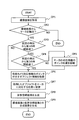
図1は、第1実施形態に係る情報処理システム100の構成の一例を示す図である。情報処理システム100には、情報処理装置1、カード2A、2Y(但し、カードの種類を区別しない場合には、単に「カード2」と称する)が含まれる。
<System configuration>
FIG. 1 is a diagram illustrating an example of a configuration of an
情報処理装置1は、例えば、携帯ゲーム機、スマートフォン、携帯電話端末、タブレット端末等の携帯型のコンピュータである。情報処理装置1は、CPU(Central Processing Unit)11と、RAM(Random Access Memory)12、ROM(Read Only Memory)
13、補助記憶装置14、前面撮像装置15A、背面撮像装置15B、ディスプレイ(表示装置)16、および各種ボタンやタッチパネル等の入力装置17が電気的に接続された情報処理装置である。なお、情報処理装置1の具体的なハードウェア構成に関しては、実施の形態毎に適宜構成要素の省略や置換、追加が行われてよい。例えば、情報処理装置1が、据え置き型のゲーム装置である場合には、撮像装置、ディスプレイ16、入力装置17等はそれぞれ独立した装置であり、周辺装置として情報処理装置1に接続される。
The
13, an
CPU11は、中央処理装置であり、RAM12およびROM13等に展開された命令
及びデータを処理することで、RAM12、補助記憶装置14等の、情報処理装置1に備えられた各構成要素を制御する。また、RAM12は、主記憶装置であり、CPU11によって制御され、各種命令やデータが書き込まれ、読み出される。即ち、CPU11、RAM12、およびROM13は、情報処理装置1の制御部を構成する。
The
補助記憶装置14は、不揮発性の記憶装置であり、主に情報処理装置1の電源を落としても保持したい情報、例えば、RAM12にロードされる情報処理装置1のOS(Operating System)や、後述する処理を実行するための各種プログラム、情報処理装置1によって使用される各種データ、等が書き込まれ、読み出される。補助記憶装置14としては、例えば、EEPROM(Electrically Erasable Programmable ROM)やHDD(Hard Disk Drive)等を用いることが出来る。また、補助記憶装置14として、情報処理装置1に
対して着脱可能に装着される可搬媒体が用いられてもよい。可搬媒体の例としては、EEPROM等によるメモリーカード、CD(Compact Disc)、DVD(Digital Versatile Disc)およびBD(Blu-ray(登録商標) Disc)等が挙げられる。可搬媒体による補助記憶装置14と、可搬型ではない補助記憶装置14とは、組み合わせて用いることも可能である。
The
前面撮像装置15A、背面撮像装置15Bは、それぞれ、前面カメラ15A、背面カメラ15Bともいう。情報処理装置1の前面とは、例えば、ディスプレイ16の表示画面と同じ面をいう。情報処理装置1の背面とは、例えば、ディスプレイ16の表示画面の対向する面をいう。前面カメラ15Aは、例えば、情報処理装置1の前面に、撮像方向がディスプレイ16の表示画面の向きと同じになるように設置されている。背面カメラ15Bは、例えば、情報処理装置1の背面に、撮像方向が前面カメラ15Aと逆方向になるように設置されている。背面カメラ15Bは、例えば、立体視用に2つ備えられてもよい。なお、前面撮像装置15A、背面撮像装置15Bを特に区別しない場合には、単に、撮像装置15と称する。
The
カード2A、2Yには、印刷等の方法で互いに異なるマーカ3A、3Y(但し、マーカの種類を区別しない場合には、単に「マーカ3」と称する)が付されている。これらマーカ3は、情報処理装置1によって表示される仮想オブジェクトと対応付けられており、該マーカ3に対応付けられた仮想オブジェクトが表示される際の位置の基準を示す指標である。図1においてカード2は2枚示されているが、用いられるカード2は1枚であってもよいし、2枚以上であってもよい。
The
マーカ3Aは、例えば、情報処理装置1によって、所定のキャラクタを模した仮想オブジェクトと対応付けられている。また、マーカ3Aは、例えば、対応付けられている仮想オブジェクトの形態との関連がユーザから認識できる特徴を含む。マーカ3Aは、例えば、対応付けられている仮想オブジェクトの形態の少なくとも一部を模した図形である。具体的には、例えば、マーカ3Aは、対応付けられた仮想オブジェクトの原型となるキャラクタの顔である。ただし、図面上では、便宜上、マーカ3Aは、アルファベットで示されている。また、マーカ3Aが印刷されているカード2Aは、例えば、紙のカード、プリペイドカード等であってもよい。
The
マーカ3Yは、例えば、情報処理装置1によって、所定の仮想オブジェクトと対応付けられている。また、マーカ3Yは、例えば、マーカ3Aとは異なり、対応付けられている仮想オブジェクトの形態との関連がユーザから視認できる特徴を含まない。マーカ3Yは、例えば、紙のカード、マーカ3Aが印刷されているプリペイドカードの台紙等である。以降、マーカ3Yは、基準マーカ3Yと称することもある。
The
第1実施形態において、仮想オブジェクトは、情報処理装置1のディスプレイ16にお
いて、撮像画像内の対応付けられたマーカ3に対して所定位置に配置されて撮像画像に対して合成表示される。また、仮想オブジェクトは、上下、前後、および左右の方向を有する。そのため、マーカ3は、仮想オブジェクトの表示姿勢を特定することが可能なものであることが好ましい。即ち、マーカ3は、撮像装置15を用いて撮像されることで、撮像装置15に対する位置および姿勢を特定可能な記号、文字、図形、絵、およびそれらの組み合わせ等であることが好ましい。なお、第1実施形態において、姿勢は、直交する3軸によって構成される座標系において特定される。
In the first embodiment, the virtual object is arranged at a predetermined position on the
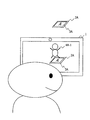
図2は、第1実施形態に係る情報処理装置1の第1のAR処理の一例を示す図である。第1のAR処理では、背面カメラ15Bによるマーカの検出が所定時間中断し、再開される度に、該マーカに対応してディスプレイ16に表示される仮想オブジェクトが変化する。
FIG. 2 is a diagram illustrating an example of the first AR process of the
例えば、背面カメラ15Bによるマーカ3Aの初回の検出時には、マーカ3Aに対応する所定の位置に仮想オブジェクト4A−1が表示される。例えば、カード2Aを背面カメラ15Bの撮像範囲から一旦外して戻す、カード2Aを手で隠す等のユーザの行為により、背面カメラ15Bによるマーカ3Aの検出が中断され再開された場合には、マーカ3Aに基づく所定の位置に仮想オブジェクト4A−2が表示される。さらに、同様の行為が行われた場合には、マーカ3Aに対応する所定の位置に表示される仮想オブジェクトは、仮想オブジェクト4A−3に変化する。
For example, when the
すなわち、第1のAR処理では、情報処理装置1は、前回のマーカ3の検出と今回のマーカ3の検出との間隔が所定時間以上である場合には、前回表示された仮想オブジェクトとは異なる仮想オブジェクトをマーカ3に基づく所定の位置に表示する。所定時間は、例えば、1秒である。
That is, in the first AR process, the
上記第1のAR処理を実現するための情報処理装置1が備える機能について説明する。第1実施形態に係る情報処理装置1は、所謂AR機能を備えた情報処理装置である。情報処理装置1は、撮像装置15を用いて撮像された実空間の撮像画像に、仮想カメラを用いて描画(レンダリング)された仮想空間内の仮想オブジェクトを合成して、ディスプレイ16に表示する機能を有する。本実施形態において、仮想オブジェクトは、3次元の画像データである。但し、仮想オブジェクトは、2次元の画像データであってもよい。
Functions provided in the
図3は、第1実施形態に係る情報処理装置1の機能構成の一例を示す図である。情報処理装置1は、CPU11が、RAM12に展開された各種プログラムを解釈および実行することで、撮像画像取得部21、特徴検出部22、姿勢検出部23、表示基準情報記憶部24、オブジェクト決定部25、画像生成部26、及び表示制御部27を備える情報処理装置として機能する。第1実施形態では、これらの機能がいずれも汎用のCPU11によって実行される例について説明しているが、これらの機能は、その一部または全部が、1または複数の専用のプロセッサによって実現されてもよい。
FIG. 3 is a diagram illustrating an example of a functional configuration of the
撮像画像取得部21は、撮像装置15によって撮像された撮像画像を取得する。撮像画像は、例えば、撮像装置15の撮像レートで取得される。例えば、撮像装置15の撮像レートが60fps(frame per second)である場合には、撮像画像取得部21は、60分の1秒毎に撮像画像を取得する。なお、前面撮像装置15Aと背面撮像装置15Bとは、両方が起動することはなく、いずれか一方が起動している場合には、もう一方は無効となる。また、前面撮像装置15Aと背面撮像装置15Bとの有効又は無効の状態の情報は、例えば、フラグで管理される。このフラグは、例えば、各撮像装置15に対してそれぞれ準備されてもよい。例えば、フラグが1である場合には、対応する撮像装置15は有効であることが示される。このフラグによって撮像画像がいずれの撮像装置15によって撮像
されたかを判定することが可能となる。
The captured
特徴検出部22は、撮像装置15によって撮像された画像に対して、例えばパターンマッチング等の画像処理を行うことによって、当該画像に含まれるマーカ3を検出することができる。マーカ3の検出は、例えば、画像認識エンジンを用いて行われる。また、特徴検出部22は、撮像された画像に含まれるマーカ3の検出とともに、該マーカ3の位置情報も検出することができる。マーカ3の位置情報は、例えば、ディスプレイ16の画面内のマーカ3の座標等である。
The
姿勢検出部23は、検出されたマーカ3に基づいて、該マーカ3の撮像画像に撮像された空間における位置および姿勢を検出し、表示基準情報を生成する。表示基準情報記憶部24は、仮想空間に配置される仮想オブジェクトの位置および姿勢を決定するための表示基準情報を記憶する。表示基準情報記憶部24は、例えば、RAM12の記憶領域に作成される。第1実施形態において、表示基準情報とは、仮想空間内における仮想オブジェクトの位置および姿勢を示すために用いられる基準である。但し、表示基準情報は、仮想空間内における仮想オブジェクトの位置および姿勢の何れか一方のみを示すために用いられる基準であってもよい。第1実施形態の姿勢検出部23は、表示基準情報として、マーカ3の中心点を原点とし、互いに直交する3軸を用いたマーカ座標系を、マーカ3毎に取得する。ただし、表示基準情報として、撮像画像そのもの等、マーカ座標系以外のものが用いられてもよい。また、複数のマーカ3間で、1つのマーカ座標系を共有して用いることも可能である。実空間に配置されたマーカ3を基準として仮想空間の座標系が定義されることにより、実空間と仮想空間とを対応付けることができる。なお、実空間と仮想空間との対応付けには、マーカ座標系を用いる方法以外の方法が採用されてもよい。
Based on the detected
姿勢検出部23は、撮像画像が取得される度に、該撮像装置内のマーカ3の位置及び姿勢を検出し、表示基準情報記憶部24に記憶される表示基準情報を更新する。したがって、第1実施形態では、撮像装置15の移動や、マーカ3の移動とともに変化する撮像装置15に対する最新のマーカ3の位置および姿勢の変化に従って、表示基準情報記憶部24によって記憶されている表示基準情報が更新される。
The
第1実施形態において、仮想空間に配置される仮想オブジェクトは、当該仮想オブジェクトが関連付けられたマーカ3のマーカ座標系に配置される。姿勢検出部23は、撮像画像に含まれるマーカ3の見え方から、撮像装置15に対するマーカ3の位置および姿勢を算出することで、マーカ座標系を取得することができる。マーカ座標系における仮想カメラの位置および姿勢は、実空間の撮像装置15の位置および姿勢と一致される。このため、マーカ3に基づいて仮想空間が定義され、当該仮想空間において、撮像装置15の位置や撮像方向を変化させると、ディスプレイ16に表示される仮想空間の画像も変化する。
In the first embodiment, the virtual object arranged in the virtual space is arranged in the marker coordinate system of the
オブジェクト決定部25は、検出されたマーカ3に基づく所定の位置に配置される仮想オブジェクトを決定する。オブジェクト決定部25は、例えば、マーカの認識状況に応じて、背面カメラ対応情報を参照し、検出されたマーカ3に基づく所定の位置に配置される仮想オブジェクトを決定する。マーカの認識状況は、例えば、前回の検出から今回の検出までの経過時間が所定範囲内にあるか否か、前回の検出から今回の検出までの経過時間が所定範囲内にある検出の回数等である。詳細は後述される。
The
画像生成部26は、仮想空間に、表示基準情報記憶部24によって記憶されている表示基準情報に従った位置および姿勢で仮想オブジェクトを配置し、仮想カメラから見た仮想空間の画像を生成することで、仮想空間画像を描画(レンダリング)する。そして、第1実施形態に係る情報処理装置1は、上記説明したAR機能のために、撮像画像取得部21によって取得された撮像画像と、画像生成部26によって生成された仮想オブジェクトを
含む仮想空間画像と、を重畳した合成画像を生成する。
The
表示制御部27は、生成された合成画像を、表示装置であるディスプレイ16によって表示させる。このようにすることで、ユーザは、現実空間に、実際に仮想オブジェクトが存在するかのような感覚を得ることが出来る。
The
次に、情報処理装置1が保持する情報について説明する。情報処理装置1は、補助記憶装置14に、マーカ情報、オブジェクト情報、背面カメラ対応情報、前面カメラ対応情報、一時的対応情報、姿勢対応情報を保持する。なお、前面カメラ対応情報、一時的対応情報、姿勢対応情報については、第2実施形態以降で説明する。
Next, information held by the
マーカ情報は、マーカ3に関する情報である。マーカ情報には、例えば、マーカ3を識別するためのマーカID、マーカ画像、マーカサイズ、マーカ3に対する仮想オブジェクトの配置位置、オブジェクトの表示サイズ等が含まれる。マーカ画像は、マーカ3の外観を示す画像である。また、マーカサイズは、マーカ3の縦横の長さ等、マーカ3の大きさを示す情報である。マーカ3に対する仮想オブジェクトの配置位置は、例えば、マーカ3に対する仮想オブジェクトを配置する位置であって、例えば、マーカ3と仮想オブジェクトとの距離である。マーカ情報は、情報処理システム100において使用される各マーカ3に対して存在する。
The marker information is information related to the
オブジェクト情報は、仮想オブジェクトに関する情報である。オブジェクト情報には、例えば、仮想オブジェクトを識別するためのオブジェクトIDおよびオブジェクトのデータが含まれる。オブジェクト情報は、情報処理システム100において使用される各オブジェクトについて存在する。
The object information is information regarding the virtual object. The object information includes, for example, an object ID for identifying a virtual object and object data. Object information exists for each object used in the
図4は、第1実施形態に係る背面カメラ対応情報の一例を示す図である。背面カメラ対応情報は、マーカ3と仮想オブジェクトとの関連付けの情報であり、検出されたマーカ3に基づく所定の位置に配置される仮想オブジェクトの決定の際に参照される情報である。
FIG. 4 is a diagram illustrating an example of back camera correspondence information according to the first embodiment. The rear camera correspondence information is information for associating the
背面カメラ対応情報には、例えば、マーカID、仮想オブジェクトID、ポインタが含まれる。第1実施形態において、背面カメラ対応情報では、1つのマーカに対して、複数の仮想オブジェクトが関連付けられており、ポインタが指し示す仮想オブジェクトが、該当するマーカ3に基づく所定の位置に配置される。ポインタは、例えば、該当マーカの前回の検出から今回の検出までの経過時間が所定範囲内の時間である場合に、オブジェクト決定部25によって別の仮想オブジェクトに移動される。詳細は後述する。ポインタの移動先は、例えば、ランダムであってもよいし、仮想オブジェクトのリストに従って決定されてもよい。ポインタが仮想オブジェクトのリストの並び順に移動する場合には、ポインタは循環的に移動するようにしてもよい。すなわち、ポインタがリストの最後にたどり着いた場合には、ポインタは、次に、リストの最初の仮想オブジェクトに移動するようにしてもよい。
The back camera correspondence information includes, for example, a marker ID, a virtual object ID, and a pointer. In the first embodiment, in the rear camera correspondence information, a plurality of virtual objects are associated with one marker, and the virtual object pointed to by the pointer is arranged at a predetermined position based on the
なお、第1実施形態では、背面カメラ対応情報は、情報処理システム100内で用いられる全てのマーカ3についての情報が保持される。基準マーカ3Yの仮想オブジェクトとの関連付けの情報も背面カメラ対応情報に保持される。ただし、全てのマーカ3に対して複数の仮想オブジェクト4が関連付けられていなくともよく、1つのマーカ3に関連付けられる仮想オブジェクトは1つであってもよい。例えば、基準マーカ3Yに関連付けられる仮想オブジェクトは、仮想オブジェクト4Yの1つである。
In the first embodiment, the back camera correspondence information holds information about all the
<処理の流れ>
次に、第1実施形態において実行される処理の流れを説明する。なお、第1実施形態に
係るフローチャートに示された処理の具体的な内容および処理順序は、本発明を実施するための一例である。具体的な処理内容および処理順序は、本発明の実施の形態毎に適宜選択されてよい。
<Process flow>
Next, the flow of processing executed in the first embodiment will be described. The specific contents and processing order of the processing shown in the flowchart according to the first embodiment are an example for carrying out the present invention. Specific processing contents and processing order may be appropriately selected for each embodiment of the present invention.
図5は、第1のAR処理のフローチャートの一例である。図5に示されるフローチャートは、情報処理装置1において、AR機能を起動するユーザ操作が受け付けられたことを契機として開始される。
FIG. 5 is an example of a flowchart of the first AR process. The flowchart shown in FIG. 5 is started when the
OP1では、撮像画像取得部21は、撮像装置15によって撮像された撮像画像を取得する。これによって、図5に示されるフローチャートは、撮像装置15の撮像レート(例えば60fps)で取得される各撮像画像について実行されることになる。OP2では、特徴検出部22が、撮像画像から、撮像された空間における特徴として、マーカ情報に含まれるマーカ画像に該当するマーカ3を検出する。マーカが検出された場合には(OP2:YES)、処理がOP3に進む。マーカ3の検出は、一般的な画像認識エンジンを用いて行うことが可能である。マーカが検出されない場合には(OP2:NO)、図5に示される処理が終了する。
In OP <b> 1, the captured
OP3では、オブジェクト決定部25は、処理対象マーカ3の前回の検出から今回の検出までの計測経過時間が第1の時間閾値以上であるか否かを判定する。第1の時間閾値は、例えば、1秒である。処理対象マーカ3の前回の検出から今回の検出までの計測経過時間が第1の時間閾値以上である場合には(OP3:YES)、処理がOP4に進む。処理対象マーカ3の前回の検出から今回の検出までの計測経過時間が第1の時間閾値未満である場合には(OP3:NO)、処理がOP6に進む。
In OP3, the
なお、オブジェクト決定部25は、特徴検出部22によって検出された各マーカ3について、検出からの経過時間を計測し、計測経過時間としてメモリに記録する。計測経過時間は、該当マーカ3が撮像画像から検出される度にリセットされる。例えば、撮像画像が60fpsのレートで取得され、マーカ3が連続して検出される場合には、撮像画像が取得される度に該マーカ3の計測経過時間がリセットされる。なお、最後の検出から該当のマーカ3の検出がないまま所定時間(例えば、5分)経過すると、オブジェクト決定部2
5は、該当のマーカ3の計測経過時間を削除する。処理OP3において、処理対象のマーカ3の計測経過時間が記録されていない場合には、オブジェクト決定部25は、処理対象マーカ3の計測経過時間が第1の時間閾値未満である(OP3:NO)、と判定する。
The
5 deletes the measurement elapsed time of the
OP4では、オブジェクト決定部25は、処理対象マーカ3の計測経過時間が第2の時間閾値以上であるか否かを判定する。第2の時間閾値は、第1の時間閾値よりも長く、例えば、3〜10秒である。処理対象マーカ3の計測経過時間が第2の時間閾値以上である場合には(OP4:YES)、処理がOP6に進む。処理対象マーカ3の計測経過時間が第2の時間閾値未満である場合には(OP4:NO)、処理がOP5に進む。
In OP4, the
OP5では、オブジェクト決定部25は、処理対象マーカ3の背面カメラ対応情報内のポインタ位置を移動させる。ポインタの移動先は、ランダムであってもよいし、リスト内で現在ポインタ位置の次に位置する仮想オブジェクトであってもよい。次に処理がOP6に進む。
In OP5, the
OP6では、オブジェクト決定部25は、処理対象マーカ3の背面カメラ対応情報内のポインタが指し示す仮想オブジェクトを取得する。次に処理がOP7に進む。撮像画像から検出されたマーカ3が複数の場合には、各マーカ3についてOP3〜OP6の処理が実行される。
In OP6, the
OP7では、画像生成部26は、取得された仮想オブジェクトを、関連付けられているマーカ3に基づく所定の位置に配置する。マーカ3の位置及び姿勢は、マーカ3の検出とともに姿勢検出部23によって表示基準情報として検出されており、画像生成部26は、表示基準情報に従ってマーカ3に基づく所定の位置に仮想オブジェクトを配置する。次に処理がOP8に進む。
In OP <b> 7, the
OP8では、画像生成部26は、仮想空間の画像を生成する。画像生成部26は、マーカ座標系に配置された1または複数の仮想オブジェクトを含む仮想空間の画像を、マーカ座標系において撮像装置15と同一の位置に配置された仮想カメラの視点から描画する。仮想オブジェクトを描画するためのオブジェクトのデータは、オブジェクト情報から取得される。なお、仮想オブジェクトは、1または数フレーム毎に変化することでアニメーションしてもよい。アニメーションは、例えば、仮想オブジェクトのキャラクタが表情を変えたり、動いたりするものとすることが出来る。その後、処理はOP9に進む。
In OP8, the
OP9では、表示制御部27は、撮像画像に仮想空間の画像を重畳した合成画像を生成し、この合成画像をディスプレイ16に出力し、表示させる。
In OP9, the
図5に示されるフローチャートにおいて、第1の時間閾値及び第2の時間閾値は、手で一旦マーカ3を隠し、その後、手をどかして該マーカ3を検出し直させたり、カード2を撮像範囲から外して、その後、再度撮像範囲内に戻して該マーカを検出し直させる、といったユーザ行為を検出するためのものである。前回の検出から今回の検出までの計測経過時間が第1の時間閾値以上第2の時間閾値未満である場合には、上記のようなユーザ行為があったことが判定され、処理がOP5に進み、該当マーカ3の背面カメラ対応情報内のポインタが移動される。これによって、マーカ3を手で隠す等のユーザ行為が行われ、該マーカ3が再度検出された場合には、前回の検出時に表示されていた仮想オブジェクトとは異なる仮想オブジェクトが表示されることになる。これによって、ユーザに変化に富んだ拡張現実を提供することができ、ユーザを飽きさせないサービスを提供することができる。
In the flowchart shown in FIG. 5, the first time threshold and the second time threshold are such that the
例えば、上記のようなユーザ行為がなく、連続して撮像装置15の撮像レート(例えば、60fps)で撮像された画像からマーカ3が検出される場合には、前回の検出から今回の検出までの計測経過時間が1/60秒となる。これは第1の時間閾値(例えば、1秒)よりも短いため(OP3:NO)、処理がOP6に進み、該当マーカ3の背面カメラ対応情報のポインタの移動もなく、該当マーカ3の対応する所定の位置には前回の検出時と同じ仮想オブジェクトが表示される。なお、情報処理装置1が初めてマーカ3を検出した場合には、オブジェクト決定部25は、計測経過時間が記録されていないので、前回の検出から第1の時間閾値経過していないと判定し(OP3:NO)、処理がOP6に進む。
For example, when the
例えば、情報処理装置1が省電力状態に移行したり、ユーザによってマーカ3が撮像範囲から外されたままになったり等、例えば1分以上マーカ3が検出されずに再度マーカ3が検出された場合には、前回の検出からの計測経過時間が第2の時間閾値以上であると判定され(OP4:YES)、処理がOP6に進み、前回の検出時と同じ仮想オブジェクトが表示されることとなる。
For example, the
ただし、第1のAR処理は、図5に示されるフローチャートに限定されない。例えば、OP4の処理は省略することもできる。OP4の処理が省略される場合には、マーカ3の前回の検出から今回の検出までの時間が第2の時間閾値以上である場合にも、OP5の処理に進み、背面カメラ対応情報中のポインタが移動され、前回の検出時とは異なる仮想オブジェクトが表示される。
However, the first AR process is not limited to the flowchart shown in FIG. For example, the process of OP4 can be omitted. When the process of OP4 is omitted, even when the time from the previous detection of the
また、オブジェクト決定部25は、マーカ3の検出からの計測経過時間が、例えば、所定時間(例えば、5分)以上になると、該マーカ3の計測経過時間の記録を削除する。この場合に、図5に示されるフローチャートの処理では、次に該当のマーカ3が検出された場合には、背面カメラ対応情報中のポインタが指し示す仮想オブジェクト、すなわち、前回の該当のマーカ3の検出時に表示された仮想オブジェクトと同じ仮想オブジェクトが表示されることになる。これに代えて、オブジェクト決定部25は、マーカ3の計測経過時間の記録の削除に伴い、該マーカ3の背面カメラ対応情報中のポインタの位置を初期設定に戻すようにしてもよい。背面カメラ対応情報中のポインタの初期設定の位置は、例えば、該当のマーカ3に関連付けられる複数の仮想オブジェクトのリストの先頭である。
Further, the
<第1実施形態の作用効果>
第1実施形態の第1のAR処理では、マーカ3の認識状況に応じて、該マーカ3に対応する位置に配置される仮想オブジェクトが変化する。これによって、AR処理を視覚的変化に富んだエンターテイメント性の高いものとすることができる。
<Operational effects of the first embodiment>
In the first AR process of the first embodiment, the virtual object arranged at the position corresponding to the
<第1のAR処理の変形例>
第1のAR処理では、マーカ3の前回の検出からの経過時間が第1の時間閾値以上第2の時間閾値未満の範囲内で今回の検出が発生する度に、マーカ3に基づく所定の位置に配置される仮想オブジェクトが変化する。これに代えて、マーカ3が連続して検出される時間又は回数に応じて、マーカ3に基づく所定の位置に配置される仮想オブジェクトが変化するようにしてもよい。
<Modification of first AR processing>
In the first AR processing, a predetermined position based on the
例えば、オブジェクト決定部25は、マーカ3の最初の検出から連続して検出される時間又は回数を計数し、所定時間又は所定回数に達した場合に、該当マーカ3の背面カメラ対応情報のポインタを移動させるようにする。これによって、マーカ3が検出される間、時間経過に応じて、マーカ3に基づく所定の位置に表示される仮想オブジェクトが変化する。マーカ3が検出されない場合や、マーカ3の最初の検出から連続して検出される時間又は回数が所定時間又は所定回数に達した場合には、該マーカ3の最初の検出から連続して検出される時間又は回数のカウンタはリセットされる。
For example, the
また、マーカ3の前回の検出からの計測経過時間が第1の時間閾値以上第2の時間閾値未満の範囲内で発生する検出の回数に応じて、マーカ3に基づく所定の位置に配置される仮想オブジェクトが変化するようにしてもよい。すなわち、例えば、ユーザが撮像範囲にマーカ3を出し入れしたりするような、情報処理装置1にマーカ3を認識し直させるユーザ行為の回数に応じて、該マーカ3に基づく所定の位置に配置される仮想オブジェクトが変化するようにしてもよい。この場合には、オブジェクト決定部25は、検出される各マーカ3について、前回の検出からの計測経過時間が第1の時間閾値以上第2の時間閾値未満の範囲内で発生する検出の回数を計数する。該検出の回数のカウンタは、例えば、マーカ3の前回の検出からの計測経過時間が第1の時間閾値以上第2の時間閾値未満の範囲内で検出が発生した場合に1加算され、該当マーカ3の前回の検出からの計測経過時間が第2の時間閾値以上である検出が発生した場合にリセットされる。例えば、前回の検出からの計測経過時間が第1の時間閾値以上第2の時間閾値未満の範囲内で発生する検出の回数が、2回ごとに、すなわち、情報処理装置1にマーカ3を認識し直させるユーザ行為が2回行われる毎に、オブジェクト決定部25は、該当マーカ3の背面カメラ対応情報のポインタを移動させる。
In addition, the measurement elapsed time from the previous detection of the
また、第1のAR処理では、マーカ3の前回の検出からの計測経過時間が第1の時間閾値以上第2の時間閾値未満の範囲内での検出が発生する度に、マーカ3に基づく位置に配置される仮想オブジェクトが変化するが、これに代えて、仮想オブジェクトの状態、動作等の態様が変化してもよい。例えば、仮想オブジェクトが所定のキャラクタである場合に
は、マーカ3の前回の検出からの計測経過時間が第1の時間閾値以上第2の時間閾値未満の範囲内での検出が発生する度に、該キャラクタの表情、服装などの外観が変化したり、該キャラクタの姿勢やポーズなどが変わったり、眠ったり走ったりという動作が変化したりしてもよい。
Further, in the first AR processing, the position based on the
これらは、例えば、背面カメラ対応情報において、マーカ3と仮想オブジェクトとの関連付けに、さらに態様を関連付けておき、オブジェクト決定部25が仮想オブジェクトの決定とともに、該仮想オブジェクトに該態様を設定することで実現可能である。背面カメラ対応情報では、例えば、マーカ3には、態様として、仮想オブジェクトに実行させる命令のファイルの識別情報が関連付けられる。仮想オブジェクトの制御は、例えば、専用のプログラムによって行われており、該プログラムは、背面カメラ対応情報の態様に対応する命令を実行することによって仮想オブジェクトに該態様を実行させる。
For example, in the rear camera correspondence information, the aspect is further associated with the association between the
また、第1のAR処理は、撮像画像が、背面カメラ15Bで撮像されている場合でも、前面カメラ15Aで撮像されている場合でも、いずれの場合でも実行されるようにしてもよい。
Further, the first AR process may be executed in any case, whether the captured image is captured by the
<第2実施形態>
第2実施形態では、情報処理装置は、第2のAR処理を行う。第2のAR処理では、現実空間の撮像手段に応じて、表示される仮想オブジェクトが変化する。第2実施形態では、第1実施形態と重複する説明は省略される。
Second Embodiment
In the second embodiment, the information processing apparatus performs the second AR process. In the second AR process, the displayed virtual object changes according to the imaging means in the real space. In the second embodiment, descriptions overlapping with those in the first embodiment are omitted.
図6A及び図6Bは、第2実施形態に係る情報処理装置1の第2のAR処理の一例を示す図である。第2のAR処理では、画像が前面カメラ15A又は背面カメラ15Bのいずれで撮像されたかによって、マーカ3Aに基づく位置に配置される仮想オブジェクトが変化する。
6A and 6B are diagrams illustrating an example of the second AR process of the
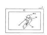
図6Aは、背面カメラ15Bでマーカ3Aを撮像した場合の画面表示例を示す図である。背面カメラ15Bでマーカ3Aを撮像した場合には、ディスプレイ16の画面のマーカ3Aに基づく所定の位置には、仮想オブジェクト4A−1が表示される。
FIG. 6A is a diagram illustrating a screen display example when the
図6Bは、前面カメラ15Aでマーカ3Aを撮像した場合の画面表示例を示す図である。前面カメラ15Aでマーカ3Aを撮像した場合には、図6Aの例と同一のマーカ3Aに基づく所定の位置には、背面カメラ15Bで撮像した場合に表示される仮想オブジェクト4A−1とは異なる仮想オブジェクト4A−4が表示される。
FIG. 6B is a diagram illustrating a screen display example when the
第2のAR処理を実行する情報処理装置1のハードウェア構成、機能構成は、ともに、第1実施形態と同様である(図1、図3参照)。第2のAR処理では、オブジェクト決定部25は、検出されたマーカ3に基づく所定の位置に配置される仮想オブジェクトの決定に、背面カメラ対応情報と前面カメラ対応情報とを用いる。
The hardware configuration and functional configuration of the
図6Cは、第2実施形態に係る背面カメラ対応情報と前面カメラ対応情報との一例を示す図である。背面カメラ対応情報は、撮像画像が背面カメラ15Bによって撮像されている場合に参照される情報である。前面カメラ対応情報は、撮像画像が前面カメラ15Aで撮像されている場合に参照される情報である。背面カメラ対応情報と前面カメラ対応情報とには、マーカIDと仮想オブジェクトIDとが含まれており、1つのマーカ3に1つの仮想オブジェクトが関連付けられている。
FIG. 6C is a diagram illustrating an example of rear camera correspondence information and front camera correspondence information according to the second embodiment. The rear camera correspondence information is information that is referred to when the captured image is captured by the
なお、第2実施形態では、背面カメラ対応情報は、情報処理システム100内で用いられる全てのマーカ3について用意されており、前面カメラ対応情報は、情報処理システム
100内で用いられる全てのマーカ3について用意されていなくてもよい。例えば、オブジェクト決定部25は、前面カメラ15Aで撮像されて、前面カメラ対応情報に検出されたマーカ3の情報が保持されていない場合には、背面カメラ対応情報を参照して、仮想オブジェクトを決定する。ただし、これに限られず、前面カメラ対応情報が情報処理システム100内で用いられる全マーカ3について用意されており、背面カメラ対応情報は、全てのマーカ3について用意されていなくてもよい。または、背面カメラ対応情報及び前面カメラ対応情報のいずれも、全てのマーカ3について用意されていなくてもよい。撮像画像から検出されたマーカ3に該当する情報が、背面カメラ対応情報及び前面カメラ対応情報のいずれにもない場合には、該マーカ3に基づく所定の位置には仮想オブジェクトが表示されない。
In the second embodiment, the back camera correspondence information is prepared for all the
<処理の流れ>
図7は、第2のAR処理のフローチャートの一例である。図7に示されるフローチャートは、情報処理装置1において、AR機能を起動するユーザ操作が受け付けられたことを契機として開始される。
<Process flow>
FIG. 7 is an example of a flowchart of the second AR process. The flowchart illustrated in FIG. 7 is started when the
OP11では、撮像画像取得部21は、撮像装置15によって撮像された撮像画像を取得する。これによって、図7に示されるフローチャートは、撮像装置15の撮像レート(例えば60fps)で取得される各撮像画像について実行されることになる。OP12では、特徴検出部22が、撮像画像から、撮像された空間における特徴として、マーカ情報に含まれるマーカ画像に該当するマーカ3を検出する。マーカ3が検出された場合には(OP12:YES)、処理がOP13に進む。マーカ3が検出されない場合には(OP12:NO)、図7に示される処理が終了する。
In OP11, the captured
OP13では、オブジェクト決定部25は、撮像画像が前面カメラ15Aによって撮像されたものであるか否かを判定する。撮像画像が前面カメラ15Aによって撮像されたものである場合には(OP13:YES)、処理がOP14に進む。撮像画像が背面カメラ15Bによって撮像されたものである場合には(OP13:NO)、処理がOP18に進む。
In OP13, the
OP14では、オブジェクト決定部25は、撮像画像が前面カメラ15Aによって撮像されたものであるので、前面カメラ対応情報から、検出されたマーカ3に関連付けられている仮想オブジェクトを取得する。なお、第2実施形態において、前面カメラ対応情報に、検出されたマーカ3の情報がない場合には、オブジェクト決定部25は、該当マーカ3の背面カメラ対応情報のポインタが指し示す仮想オブジェクトを取得する。次に処理がOP15に進む。
In OP14, since the captured image is captured by the
OP18では、オブジェクト決定部25は、撮像画像が背面カメラ15Bによって撮像されたものであるので、背面カメラ対応情報から、検出されたマーカ3に関連付けられている仮想オブジェクトを取得する。次に処理がOP15に進む。
In OP18, the
OP15〜OP17は、図5のOP7〜OP9の処理と同様である。OP15〜OP17では、取得された仮想オブジェクトがマーカ3に基づく所定の位置に配置され、仮想空間画像が生成され、撮像画像と仮想空間画像との合成画像が生成され、該合成画像がディスプレイ16に表示される。
OP15 to OP17 are the same as the processing of OP7 to OP9 in FIG. In OP15 to OP17, the acquired virtual object is arranged at a predetermined position based on the
例えば、前面カメラ対応情報において、背面カメラ対応情報ではいずれのマーカ3にも関連付けられていない仮想オブジェクトを関連付けておくことによって、該仮想オブジェクトを前面カメラ15Aで撮像した際に背面カメラ15Bで撮像している間には表示されなかったキャラクタが表示されるようにすることができる。ARマーカを撮像する際には
背面カメラ15Bが用いられることが多く、前面カメラ15Aを用いてARマーカを撮像することは少ない。そのため、前面カメラ15Aでマーカ3を撮像した際に、背面カメラ15Bで撮像している間には表示されなかった仮想オブジェクトが表示されることによって、該仮想オブジェクトを隠しキャラクタとしてユーザに提示することができ、ユーザに驚き、興奮等を与えることができる。
For example, in the front camera correspondence information, by associating a virtual object that is not associated with any
<第2実施形態の作用効果>
第2のAR処理では、マーカ3の検出手段が前面カメラ15A、背面カメラ15Bのいずれであるかによって、該マーカ3に対応する位置に配置される仮想オブジェクトが変化する。これによって、AR処理を視覚的変化に富んだエンターテイメント性の高いものとすることができる。
<Effects of Second Embodiment>
In the second AR process, the virtual object arranged at the position corresponding to the
<第2のAR処理の変形例>
第2のAR処理では、前面カメラ15A、背面カメラ15Bのいずれで撮像されたかによって、マーカ3に基づく所定の位置に配置される仮想オブジェクトが変化する。前面カメラ15A、背面カメラ15Bが、それぞれ複数備えられる場合には、各撮像装置について対応情報を用意することで、いずれの撮像装置で撮像されたかによって、マーカ3に対応する位置に表示される仮想オブジェクトを切り替えることができる。例えば、立体視用に、背面カメラ15Bが、右目用カメラと左目用カメラとを備える場合に、右目用カメラ対応情報と、左目用カメラ対応情報とを用意することで、右目用カメラで撮像された場合と、左目用カメラで撮像された場合とで、マーカ3に基づく所定の位置に表示される仮想オブジェクトを切り替えることができる。
<Modification of second AR processing>
In the second AR process, a virtual object arranged at a predetermined position based on the
また、第2のAR処理では、前面カメラ15A又は背面カメラ15Bのいずれで撮像されたかによって、マーカ3に基づく所定の位置に表示される仮想オブジェクトが変化する。これに代えて、前面カメラ15A又は背面カメラ15Bのいずれで撮像されたかによって、マーカ3に基づく所定の位置に表示される仮想オブジェクトの態様を変化させてもよい。これは、例えば、前面カメラ対応情報において、背面カメラ対応情報において該当マーカ3に関連付けられている仮想オブジェクトと同じ仮想オブジェクトに背面カメラ対応情報とは異なる態様を示す命令を関連付けることによって、実現可能である。仮想オブジェクトの態様は、第1実施形態で説明されたものと同様である。
In the second AR process, the virtual object displayed at a predetermined position based on the
また、第2のAR処理は、第1のAR処理と組み合わせることも可能である。第1のAR処理と第2のAR処理とを組み合わせる場合には、例えば、背面カメラ対応情報、前面カメラ対応情報のいずれか一方、又は、両方を、第1実施形態に係る背面カメラ対応情報と同様の構成にし、図7のOP14、OP18のいずれか一方又は両方の処理を、図5のOP2〜OP6の処理に置き換えることによって実現される。これによって、撮像画像が背面カメラ15B又は前面カメラ15Aのいずれによって撮像されたかに応じて、マーカ3の対応する位置に表示される仮想オブジェクトが変化するとともに、該マーカ3を認識し直させるユーザ行為に応じても該マーカ3の対応する位置に表示される仮想オブジェクトが変化するようになる。
Further, the second AR process can be combined with the first AR process. When combining the first AR processing and the second AR processing, for example, either one or both of the rear camera correspondence information and the front camera correspondence information is used as the rear camera correspondence information according to the first embodiment. The same configuration is realized by replacing one or both of OP14 and OP18 in FIG. 7 with the processing in OP2 to OP6 in FIG. As a result, the virtual object displayed at the corresponding position of the
また、第2のAR処理を利用して、例えば、前面カメラ15Aの起動時に、前面カメラ15Aに対応して表示される仮想オブジェクトが配置された状態で仮想空間の更新を停止してその時点での仮想空間画像を保持し、背面カメラ15Bに切り替えられた際に、背面カメラ15Bで撮像される現実空間の撮像画像に、保持されている前面カメラ15Aに対応する仮想オブジェクトを含む仮想空間画像を重畳してディスプレイ16に表示することも可能である。仮想空間の更新の停止は、例えば、操作ボタンの押下等ユーザ操作によって行われてもよいし、前面カメラ15Aから背面カメラ15Bに切り替わることを契機に行われてもよい。仮想空間の更新の停止は、例えば、特徴検出部22、姿勢検出部23の
処理、すなわち、撮像画像からのマーカ検出の処理、表示基準情報の更新を無効にすることによって達成される。これによって、前面カメラ15Aでマーカ3を撮像した場合に表示される仮想オブジェクトを、背面カメラ15Bで撮像することができる。また、同様にして、背面カメラ15Bでマーカ3を撮像した場合に表示される仮想オブジェクトを、前面カメラ15Aで撮像することも可能である。
Further, using the second AR processing, for example, when the
<第3実施形態>
第3実施形態では、情報処理装置1は、第3のAR処理を実行する。第3のAR処理では、基準マーカ3Yが検出されることによって、基準マーカ3Y以外の検出されたマーカ3に関連付けられていた仮想オブジェクトが、基準マーカ3Yに関連付けられる。第3実施形態では、第1、第2実施形態と重複する説明は省略される。
<Third Embodiment>
In the third embodiment, the
図8は、第3実施形態に係る情報処理装置1の第3のAR処理の一例を示す図である。第3のAR処理では、基準マーカ3Yとマーカ3Aとを一緒に撮像した場合に、ディスプレイ16の画面では、基準マーカ3Yに対応する位置に、マーカ3Aに対応付けられている仮想オブジェクトが移動する。以降、基準マーカ3Yに対して、基準マーカではないマーカ3Aを、ノーマルマーカと称する。
FIG. 8 is a diagram illustrating an example of the third AR process of the
図8では、ディスプレイ16の画面には、基準マーカ3Yに基づく所定の位置には、基準マーカ3Yに関連付けられている仮想オブジェクト4Yが表示される。仮想オブジェクト4Yは、木を模したオブジェクトである。
In FIG. 8, the
ノーマルマーカ3Aに基づく所定の位置には、ノーマルマーカ3Aに関連付けられている仮想オブジェクト4A−1が表示され、該仮想オブジェクト4A−1は、その後、基準マーカ3Yに基づく所定の位置に移動する。
A
第1のAR処理と同様に、ノーマルマーカ3Aを一旦撮像範囲から外して再度撮像範囲内に戻す等のユーザ行為が行われると、その都度、ノーマルマーカ3Aに基づく所定の位置には前回とは異なる仮想オブジェクト4A−2、4A−3が表示される。これらの仮想オブジェクト4A−2、4A−3も基準マーカ3Yに基づく所定の位置に移動する。このとき、既に表示されている仮想オブジェクト4A−1も画面中に残ったままで表示される。結果として、第3のAR処理では、基準マーカ3Yに、ノーマルマーカ3Aの所定の位置に表示された仮想オブジェクト4A−1、4A−2、4A−3が集まってくることとなる。
Similarly to the first AR process, whenever a user action such as once removing the
第3のAR処理では、情報処理装置1は、基準マーカ3Yとともに撮像されるノーマルマーカ3Aに対応する所定の位置に表示された仮想オブジェクトを基準マーカ3Yに関連付ける。これによって、撮像範囲からノーマルマーカ3Aが外れても基準マーカ3Yが撮像範囲内にある場合には、当初ノーマルマーカ3Aに基づく所定の位置に表示された仮想オブジェクト4は画面上の基準マーカ3Yに対応する所定の位置に表示され続ける。また、ノーマルマーカ3Aに対して第1のAR処理と同様に撮像画像から検出される度に表示される仮想オブジェクトが変化する処理が行われる場合には、ノーマルマーカ3Aに関連付けられている複数の仮想オブジェクトが同じ画面上で表示されることになる。
In the third AR process, the
図9は、一時的対応情報の一例を示す図である。一時的対応情報は、基準マーカ3Yとともにノーマルマーカ3が検出された場合に参照される情報であって、初期状態では、空である。図9に示される例は、基準マーカ3Yとともにノーマルマーカ3Aが検出された場合の一時的対応情報である。
FIG. 9 is a diagram illustrating an example of temporary correspondence information. The temporary correspondence information is information that is referred to when the
一時的対応情報には、基準マーカ3Yとノーマルマーカ3Aとがともに撮像画像から検出された場合に、検出された基準マーカ3Yとノーマルマーカ3Aとの情報が背面カメラ対応情報からコピーされる。ノーマルマーカ3Aの情報において、ポインタが指し示す仮想オブジェクトIDは、基準マーカ3Yの情報に書き込まれる。これによって、該仮想オブジェクトが基準マーカ3Yに関連付けられ、基準マーカ3Yに関連付けられる仮想オブジェクトが増える。
In the temporary correspondence information, when both the
なお、一時的対応情報において、ノーマルマーカ3Aと、基準マーカ3Yに新たに関連付けられた仮想オブジェクトとの関連付けは、維持されてもよいし、該仮想オブジェクトの基準マーカ3Yとの関連付けを契機に解消されてもよい。ノーマルマーカ3Aと基準マーカ3Yに新たに関連付けられた仮想オブジェクトとの関連付けが解消される場合には、ノーマルマーカ3Aの検出の度に、元々ノーマルマーカ3Aに関連付けられていた仮想オブジェクトが基準マーカ3Yとの関連付けに移動してしまうので、最終的に、ノーマルマーカ3Aが検出されてもノーマルマーカ3Aの対応する位置に仮想オブジェクトが表示されなくなる。
In the temporary correspondence information, the association between the
<処理の流れ>
図10A及び図10Bは、第3のAR処理のフローチャートの一例である。図10A及び図10Bに示されるフローチャートは、情報処理装置1において、AR機能を起動するユーザ操作が受け付けられたことを契機として開始される。
<Process flow>
10A and 10B are examples of a flowchart of the third AR process. The flowcharts shown in FIGS. 10A and 10B are started when the
OP21では、撮像画像取得部21は、撮像装置15によって撮像された撮像画像を取得する。これによって、図10A及び図10Bに示されるフローチャートは、撮像装置15の撮像レート(例えば60fps)で取得される各撮像画像について実行されることになる。OP22では、特徴検出部22が、撮像画像から、撮像された空間における特徴として、マーカ情報に含まれるマーカ画像に該当するマーカ3を検出する。マーカが検出された場合には(OP22:YES)、処理がOP23に進む。マーカが検出されない場合には(OP22:NO)、図10A及び図10Bに示される処理が終了する。
In OP21, the captured
OP23では、特徴検出部22によって検出されたマーカ3が複数である場合には(OP23:YES)、処理がOP24に進む。特徴検出部22によって検出されたマーカ3が1つである場合には(OP23:NO)、処理がOP25に進み、第1または第2のAR処理(図5のOP3〜OP9、又は、図7のOP13〜OP18の処理)が実行される。その後、図10A及び図10Bに示される処理が終了する。
In OP23, when there are a plurality of
OP24では、オブジェクト決定部25は、検出された複数のマーカ3の中に、基準マーカ3Yが含まれるか否かを判定する。基準マーカ3Yが、検出されたマーカ3の中に含まれている場合には(OP24:YES)、処理がOP31に進む。基準マーカ3Yが検出された複数のマーカの中に含まれていない場合には(OP24:NO)、処理がOP25に進み、第1または第2のAR処理(図5のOP3〜OP9、又は、図7のOP13〜OP18の処理)が実行される。その後、図10A及び図10Bに示される処理が終了する。
In OP24, the
OP31では、オブジェクト決定部25は、基準マーカ3Yの前回の検出からの計測経過時間が所定時間以上であるか否かを判定する。所定時間は、例えば、3秒以上である。また、所定時間は、第1のAR処理の第2の時間閾値であってもよい。基準マーカ3Yの前回の検出からの計測経過時間が所定時間未満である場合には(OP31:NO)、処理がOP34に進む。基準マーカ3Yの前回の検出からの計測経過時間が所定時間以上である場合には(OP31:YES)、処理がOP32に進む。
In OP31, the
OP32では、オブジェクト決定部25は、一時的対応情報を初期化する。一時的対応
情報の初期状態は、空である。次に処理がOP33に進む。
In OP32, the
OP33では、オブジェクト決定部25は、検出された基準マーカ3Y及びノーマルマーカ3の背面カメラ対応情報を一時的対応情報にコピーする。次に処理がOP34に進む。
In OP33, the
OP34では、オブジェクト決定部25は、ノーマルマーカ3に対応する位置に配置される仮想オブジェクトを決定する。OP34の処理は、参照する情報が一時的対応情報である点以外は、第1のAR処理の図5のOP3〜OP6の処理と同様である。すなわち、オブジェクト決定部25は、ノーマルマーカ3の前回の検出からの計測経過時間が第1の時間閾値未満、又は、第2の時間閾値以上である場合には、ノーマルマーカ3の一時的対応情報内のポインタが指し示す仮想オブジェクトを、ノーマルマーカ3に基づく所定の位置に配置される仮想オブジェクトに決定する。オブジェクト決定部25は、ノーマルマーカ3の前回の検出からの計測経過時間が第1の時間閾値以上第2の時間閾値未満である場合には、ノーマルマーカ3の一時的対応情報内のポインタを移動させ、移動先の仮想オブジェクトを、ノーマルマーカ3に基づく所定の位置に配置される仮想オブジェクトに決定する。次に、処理がOP35に進む。
In OP <b> 34, the
OP35では、オブジェクト決定部25は、一時的対応情報において、OP34で新たに決定されたノーマルマーカ3に基づく所定の位置に配置される仮想オブジェクトを、基準マーカ3Yに関連付ける。次に処理がOP36に進む。
In OP35, the
OP36では、オブジェクト決定部25は、基準マーカ3Yに対応付けられる仮想オブジェクトを一時的対応情報から取得する。次に処理がOP37に進む。
In OP36, the
OP37〜OP39では、図5のOP7〜OP9と同様の処理が行われる。すなわち、取得された仮想オブジェクトがそれぞれ基準マーカ3Yに基づく所定の位置に配置され、仮想空間画像が生成され、撮像画像と仮想空間画像との合成画像が生成され、該合成画像がディスプレイ16に表示される。その後、図10A及び図10Bに示される処理が終了する。ただし、仮想オブジェクトが、基準マーカ3Yに新たに関連付けられたものである場合には、該仮想オブジェクトは、基準マーカ3Yに基づく所定の位置として、まず、ノーマルマーカ3に基づく所定の位置に配置され、基準マーカ3Yに基づく他の所定の位置へと移動するように設定される。この仮想オブジェクトの動作は、該仮想オブジェクトが、基準マーカ3Yに新たに関連づけられ、基準マーカ3Yに基づいて配置される仮想オブジェクトとして取得されるときに、オブジェクト決定部25によって、該仮想オブジェクトに設定される。また、仮想オブジェクトの制御は、例えば、専用のプログラムによって行われており、仮想オブジェクトの上記動作は、該プログラムによって制御される。
In OP37 to OP39, the same processing as OP7 to OP9 in FIG. 5 is performed. That is, the acquired virtual objects are respectively arranged at predetermined positions based on the
OP35において、ノーマルマーカ3に基づく所定の位置に配置されることが決定された仮想オブジェクトは、一時的対応情報において、基準マーカ3Yに関連付けられる。これによって、例えば、該ノーマルマーカ3が撮像範囲から外れて検出されなくなっても、ノーマルマーカ3に関連付けられていた該仮想オブジェクトは、一時的対応情報において基準マーカ3Yに関連付けられているので、表示され続けることになる。
In OP35, the virtual object determined to be arranged at a predetermined position based on the
また、ノーマルマーカ3については、第1のAR処理と同様の処理が行われるため、基準マーカ3Yが撮像されている間に、ノーマルマーカ3を撮像範囲に出し入れすることによって、ノーマルマーカ3に関連付けられている複数の仮想オブジェクトが次々に基準マーカ3Yに関連付けられることになる。ディスプレイ16の画面では、画面中の仮想オブジェクトが増えていくことなり、最終的には、ノーマルマーカ3に関連付けられているすべての仮想オブジェクトが基準マーカ3Yに対応する所定の位置に集合するようになる。
Since the
また、仮想オブジェクトが基準マーカ3Yに新たに関連付けられた後も、該仮想オブジェクトと、ノーマルマーカ3との関連付けが維持される場合には、ノーマルマーカ3を情報処理装置1に認識し直させるユーザ行為の繰り返しによって、該仮想オブジェクトと同じ仮想オブジェクトが表示されることになる。これによって、同じ画面上に、同じ仮想オブジェクトが複数表示させることができる。
Further, when the association between the virtual object and the
第3のAR処理によって、ノーマルマーカ3に関連付けられている仮想オブジェクトが基準マーカ3Yに関連付けられるので、一つのノーマルマーカ3に関連付けられている複数の仮想オブジェクトを同じ画面上に表示させることができる。
Since the virtual object associated with the
<第3実施形態の作用効果>
第3のAR処理では、基準マーカ3Yとノーマルマーカ3とがともに検出されることによって、ノーマルマーカ3に関連付けられる仮想オブジェクトが基準マーカ3Yに関連付けられる。これによって、AR処理を視覚的変化に富んだエンターテイメント性の高いものとすることができる。
<Operational effects of the third embodiment>
In the third AR process, when both the
<第3のAR処理の変形例>
第3のAR処理において、基準マーカ3Yに基づく仮想オブジェクトの配置ポイントがあらかじめ複数設定されており、ノーマルマーカ3に基づく所定の位置に配置される仮想オブジェクトに、最寄りの配置ポイントに移動させる命令を実行させるようにしてもよい。すでに、最寄りの配置ポイントに別の仮想オブジェクトが配置されている場合には、空いている配置ポイントのうちノーマルマーカ3に基づく所定の位置に最も近い配置ポイントに移動させるようにする。また、ノーマルマーカ3に基づく所定の位置に配置される仮想オブジェクトが最寄りの配置ポイントへ移動中に、撮像画像内での基準マーカ3Yの位置が変わり、移動先であった最寄りの配置ポイントも移動した場合には、新たに仮想オブジェクトから最寄りの配置ポイントを検出して、該検出した配置ポイントを該仮想オブジェクトの移動先としてもよい。仮想オブジェクトの制御は、例えば、専用のプログラムによって行われており、該プログラムに最寄りの配置ポイントに移動させる命令を実行させる。
<Modification of third AR processing>
In the third AR processing, a plurality of virtual object placement points based on the
また、第3のAR処理において、基準マーカ3Yは、背面カメラ対応情報又は前面カメラ対応情報において、いずれの仮想オブジェクトとも関連付けられていなくともよい。基準マーカ3Yとノーマルマーカ3とがともに検出された場合には、ノーマルマーカ3に関連付けられた仮想オブジェクトが表示されることになる。
In the third AR process, the
また、第3実施形態では、第3のAR処理において、ノーマルマーカ3については、個別に第1のAR処理が実行されていたが、これに限られない。例えば、第3のAR処理において、ノーマルマーカ3には複数の仮想オブジェクトが関連付けられておらず、1つの仮想オブジェクトが関連付けられていてもよい。この場合には、例えば、撮像範囲にノーマルマーカ3を出し入れするたびに、基準マーカ3Yに関連付けられる、ノーマルマーカ3に関連付けられる仮想オブジェクトの数が増えるようにしてもよい。または、第3のAR処理において、ノーマルマーカ3は、連続して検出される時間に応じて、仮想オブジェクトを変化させるようにしてもよい。
Further, in the third embodiment, in the third AR process, the first AR process is individually executed for the
また、第3実施形態では、一時的対応情報において、ノーマルマーカ3に関連付けられている仮想オブジェクトの基準マーカ3Yへの対応付けは、該仮想オブジェクトが所定の位置に配置される前に行われる(図10B参照)。これに限られず、一時的対応情報におけるノーマルマーカ3に関連付けられている仮想オブジェクトの基準マーカ3Yへの対応付けは、例えば、該仮想オブジェクトをノーマルマーカ3に対応する所定の位置に配置し
、所定時間経過後に行われてもよい。
In the third embodiment, in the temporary correspondence information, the virtual object associated with the
この場合には、例えば、図10Bのフローチャートの、OP34とOP35との処理の間に、該当のノーマルマーカ3が連続して検出される回数又は時間が所定回数又は所定時間に達しているか否かの判定を追加することによって実現可能である。該当のノーマルマーカ3が連続して検出される回数又は時間が所定回数又は所定時間に達している場合には、処理がOP35に進み、該ノーマルマーカ3に関連付けられている仮想オブジェクトの基準マーカ3Yへの対応付けが行われる。該当のノーマルマーカ3が連続して検出される回数又は時間が所定回数又は所定時間に達していない場合には、処理がOP36に進む。
In this case, for example, whether or not the number of times or the time that the corresponding
これによって、ディスプレイ16の画面上では、ノーマルマーカ3と基準マーカ3Yとが撮像された場合に、ノーマルマーカ3に対応する所定の位置に、所定時間、ノーマルマーカ3に関連付けられている仮想オブジェクトが表示される。例えば、所定時間経過後、該仮想オブジェクトが基準マーカ3Yへ対応付けられることによって、ディスプレイ16の画面上では、該仮想オブジェクトが基準マーカ3Yの所定の配置ポイントに移動する。
Thereby, on the screen of the
<第4実施形態>
第4実施形態では、情報処理装置は、第4のAR処理を行う。第4のAR処理では、マーカ3の姿勢に応じて、表示される仮想オブジェクトの態様が変化する。第4実施形態では、第1〜第3実施形態と重複する説明は省略される。
<Fourth embodiment>
In the fourth embodiment, the information processing apparatus performs a fourth AR process. In the fourth AR process, the mode of the displayed virtual object changes according to the posture of the
図11A及び図11Bは、第4のAR処理の一例を示す図である。図11A及び図11Bの画面では、同一のマーカ3Aが表示されており、双方の画面には同一の仮想オブジェクト4A−1が表示されている。図11Aと図11Bとでは、マーカ3Aの姿勢が異なり、それに応じて、仮想オブジェクト4A−1の動作も異なる。図11Aでは、マーカ3Aは、ディスプレイ16の表示画面の水平方向及び垂直方向に対して所定の角度で傾いて認識されて、仮想オブジェクト4A−1は、カード2Aを坂に見立てて滑り下りる動作を行っている。図11Bでは、マーカ3Aは、ディスプレイ16の表示画面の水平方向の傾きがない状態で認識されて、仮想オブジェクト4A−1は、カード2Aを壁に見立てて登っている。
11A and 11B are diagrams illustrating an example of the fourth AR process. 11A and 11B, the
第4のAR処理を実行する情報処理装置1のハードウェア構成、機能構成はともに、第1実施形態と同様である(図1、図3参照)。第4のAR処理では、オブジェクト決定部25は、検出されたマーカ3に基づく所定の位置に配置される仮想オブジェクトの決定に、姿勢対応情報を用いる。
Both the hardware configuration and the functional configuration of the
図12は、姿勢対応情報の一例を示す図である。姿勢対応情報は、マーカ3と仮想オブジェクトとの関連付けと、該マーカ3の姿勢と該仮想オブジェクトの動作との関連付けと、を保持する。姿勢対応情報において、動作は、仮想オブジェクトに所定の動作を実行させるための命令が記載されたファイルの識別情報が保持される。姿勢対応情報とは別に、例えば、補助記憶装置14には、各姿勢の、互いに直交する3軸で構成される共通座標系の原点を始点とするベクトルでの定義が保持されている。姿勢対応情報において、姿勢は、例えば、該姿勢の定義が記載されるファイル等の識別情報が保持される。姿勢を定義するベクトルの値は、該姿勢を検出する基準となるベクトルであって、姿勢の検出の際には、定義されたベクトルに所定範囲が加味されて、最も近いものが検出される。
FIG. 12 is a diagram illustrating an example of posture correspondence information. The posture correspondence information holds the association between the
なお、図12では、態様の例として、動作を姿勢に関連付けているが、これに限られず、例えば、キャラクタの表情、服装等の外観の一部が関連付けられてもよい。また、姿勢対応情報とは別に、例えば、補助記憶装置14には、態様の識別情報と、該態様を仮想オブジェクトに実行させるための命令を含むファイルとの対応付けの定義が保持されている
。
In FIG. 12, as an example of the mode, the motion is associated with the posture, but is not limited thereto, and for example, a part of the appearance of the character's facial expression, clothes, and the like may be associated. In addition to the posture correspondence information, for example, the
図13は、第4のAR処理のフローチャートの一例である。図13に示されるフローチャートは、情報処理装置1において、AR機能を起動するユーザ操作が受け付けられたことを契機として開始される。
FIG. 13 is an example of a flowchart of the fourth AR process. The flowchart illustrated in FIG. 13 is started when the
OP41では、撮像画像取得部21は、撮像装置15によって撮像された撮像画像を取得する。これによって、図13に示されるフローチャートは、撮像装置15の撮像レート(例えば60fps)で取得される各撮像画像について実行されることになる。OP42では、特徴検出部22が、撮像画像から、撮像された空間における特徴として、マーカ情報に含まれるマーカ画像に該当するマーカ3を検出し、マーカが検出された場合には(OP42:YES)、処理がOP43に進む。マーカが検出されない場合には(OP42:NO)、図13に示される処理が終了する。
In OP41, the captured
OP43では、姿勢検出部23は、検出されたマーカ3の姿勢を検出する。次に処理がOP44に進む。
In OP43, the
OP44では、オブジェクト決定部25は、姿勢対応情報から、検出されたマーカ3に関連付けられる仮想オブジェクトと、検出された姿勢に関連付けられる動作とを取得する。次に処理がOP45に進む。検出されたマーカ3が複数の場合には、各マーカ3についてOP43〜OP44の処理が実行される。
In OP44, the
OP45では、画像生成部26は、取得された仮想オブジェクトを関連付けられるマーカ3に対応する所定の位置に配置し、取得された動作を実行するように設定する。マーカ3の位置及び姿勢は、マーカ3の検出とともに姿勢検出部23によって表示基準情報として検出されており、画像生成部26は、表示基準情報に従ってマーカ3の対応する所定の位置に仮想オブジェクトを配置する。次に処理がOP46に進む。
In OP45, the
OP46では、画像生成部26は、仮想空間の画像を生成する。OP47では、表示制御部27は、撮像画像に仮想空間の画像を重畳した合成画像を生成し、この合成画像をディスプレイ16に出力し、表示させる。
In OP46, the
<第4実施形態の作用効果>
第4実施形態では、検出されたマーカ3の姿勢に応じて、表示される仮想オブジェクトの態様が変化する。これによって、視覚的変化に富んだAR処理を提供することができる。また、ユーザに対して、マーカ3の姿勢変化への探究心を煽ることができる。
<Effects of Fourth Embodiment>
In the fourth embodiment, the aspect of the displayed virtual object changes according to the detected posture of the
第4実施形態では、検出されたマーカ3の姿勢に応じて、表示される仮想オブジェクトの態様が変化したが、これに代えて、マーカ3の姿勢に応じて、表示される仮想オブジェクト自体が変化してもよい。これは、姿勢対応情報において、姿勢と仮想オブジェクトとの関連付けを保持することによって実現可能である。
In the fourth embodiment, the aspect of the displayed virtual object changes according to the detected posture of the
また、第1実施形態と第4実施形態とは組み合わせて実施することも可能である。その場合には、例えば、姿勢対応情報には、マーカ3と仮想オブジェクトとの組み合わせを含めず、マーカ3に関連付けられた仮想オブジェクトは背面カメラ対応情報又は前面カメラ対応情報から取得し、取得した仮想オブジェクトの態様を姿勢対応情報から取得することによって実現可能である。
Further, the first embodiment and the fourth embodiment can be implemented in combination. In that case, for example, the posture correspondence information does not include the combination of the
<実施形態のバリエーション>
上記説明した実施形態において、表示制御部27は、撮像画像に仮想空間の画像を重畳
した合成画像を表示装置に表示させることで、ユーザが、仮想空間の画像が現実空間に重畳されて視認可能とする。但し、表示制御部27は、仮想空間の画像が現実空間に重畳されてユーザから視認されるように、表示装置に画像を表示させればよく、合成画像を表示する方式に限定されない。例えば、本発明は、HUD(Head−Up Display)や、ユーザが装着しているメガネに仮想空間画像を映写する方式等、ユーザの視界に仮想空間画像を映写することで仮想空間の画像が現実空間に重畳されてユーザから視認されるタイプの拡張現実技術に適用されてもよい。
<Variation of the embodiment>
In the embodiment described above, the
上述した実施形態において、情報処理装置1は、単体で上述の処理を行ったが、これに限られない。上述した実施形態の処理は、複数の情報処理装置で分散して行われてもよい。例えば、背面カメラ対応情報は、ネットワーク上のデータベースに配置されており、情報処理装置1が該データベースにアクセスして背面カメラ対応情報を取得してもよい。また、例えば、画像生成部26の処理を、ネットワーク上のサーバに実行させるように設計することによって、情報処理装置1がマーカ3の検出結果をサーバに送信し、該サーバが仮想空間画像を生成して情報処理装置1に送信するようにしてもよい。
In the embodiment described above, the
1 情報処理装置
2A、2Y カード
3A、3Y マーカ
21 撮像画像取得部
22 特徴検出部
23 姿勢検出部
24 表示基準情報記憶部
25 オブジェクト決定部
26 画像生成部
27 表示制御部
DESCRIPTION OF
Claims (10)
現実空間の撮像画像を取得する画像取得手段と、
前記撮像画像から特徴を検出する特徴検出手段と、
前記撮像画像が取得された際の前記撮像手段の状況として、前記撮像画像が前記複数のカメラのいずれによって撮像されたかに応じて、仮想オブジェクト又は仮想オブジェクトと該仮想オブジェクトの態様とを決定する決定手段と、
前記決定された仮想オブジェクト又は前記決定された態様の仮想オブジェクトが前記特徴に基づいて配置された仮想空間の画像を生成する画像生成手段と、
前記仮想空間の画像が現実空間に重畳されてユーザから視認されるように、表示装置に画像を表示させる表示制御手段と、
として機能させる情報処理プログラム。 A computer having a plurality of cameras in the same housing as an imaging means ,
Image acquisition means for acquiring a captured image of the real space;
Feature detection means for detecting features from the captured image;
Determination of determining a virtual object or a virtual object and an aspect of the virtual object according to which of the plurality of cameras captures the captured image as the state of the imaging unit when the captured image is acquired Means,
Image generation means for generating an image of a virtual space in which the determined virtual object or the virtual object of the determined aspect is arranged based on the characteristics;
Display control means for displaying an image on a display device so that an image of the virtual space is superimposed on a real space and visually recognized by a user;
Information processing program to function as.
前記複数のカメラの一部は、前記表示装置の表示画面と略同一の面に備えられ、
前記複数のカメラの他の一部は、前記表示装置の表示画面と略同一の面以外の面に備えられ、
前記決定手段は、前記撮像画像が取得された際の前記撮像手段の状況として、当該撮像画像が、前記表示画面と略同一の面に備えられているカメラによる撮像画像であるか、前記表示画面と略同一の面以外の面に備えられているカメラによる撮像画像であるかによって、仮想オブジェクト又は仮想オブジェクトと該仮想オブジェクトの態様とを決定する、請求項1に記載の情報処理プログラム。 The computer includes a display device in the same housing,
Some of the plurality of cameras are provided on substantially the same surface as the display screen of the display device,
The other part of the plurality of cameras is provided on a surface other than the substantially same surface as the display screen of the display device,
The determining means determines whether the captured image is an image captured by a camera provided on substantially the same surface as the display screen as the state of the imaging means when the captured image is acquired , or the display screen The information processing program according to claim 1 , wherein a virtual object or a virtual object and an aspect of the virtual object are determined depending on whether the captured image is obtained by a camera provided on a surface other than substantially the same surface.
請求項2に記載の情報処理プログラム。 The part of the plurality of cameras and the other part have a substantially reverse imaging direction based on the posture of the computer.
The information processing program according to claim 2 .
請求項1に記載の情報処理プログラム。 The determining unit changes a virtual object or a virtual object and a mode of the virtual object according to a change of the imaging unit of the captured image as a situation of the imaging unit of the captured image when the captured image is acquired. Let
The information processing program according to claim 1 .
請求項1から4のいずれか一項に記載の情報処理プログラム。 The aspect of the virtual object is defined by the appearance of the virtual object.
The information processing program according to any one of claims 1 to 4 .
請求項1から5のいずれか一項に記載の情報処理プログラム。 The aspect of the virtual object is defined by the posture of the virtual object.
The information processing program according to any one of claims 1 to 5 .
請求項1から6のいずれか一項に記載の情報処理プログラム。 The aspect of the virtual object is defined by an action to be executed by the virtual object.
The information processing program according to any one of claims 1 to 6 .
現実空間の撮像画像を取得する画像取得手段と、
前記撮像画像から特徴を検出する特徴検出手段と、
前記撮像画像が取得された際の前記撮像手段の状況として、前記撮像画像が前記複数のカメラのいずれによって撮像されたかに応じて、仮想オブジェクト又は仮想オブジェクトと該仮想オブジェクトの態様とを決定する決定手段と、
前記決定された仮想オブジェクト又は前記決定された態様の仮想オブジェクトが前記特徴に基づいて配置された仮想空間の画像を生成する画像生成手段と、
前記仮想空間の画像が現実空間に重畳されてユーザから視認されるように、表示装置に画像を表示させる表示制御手段と、
を備える情報処理装置。 A plurality of cameras as imaging means;
Image acquisition means for acquiring a captured image of the real space;
Feature detection means for detecting features from the captured image;
Determination of determining a virtual object or a virtual object and an aspect of the virtual object according to which of the plurality of cameras captures the captured image as the state of the imaging unit when the captured image is acquired Means,
Image generation means for generating an image of a virtual space in which the determined virtual object or the virtual object of the determined aspect is arranged based on the characteristics;
Display control means for displaying an image on a display device so that an image of the virtual space is superimposed on a real space and visually recognized by a user;
An information processing apparatus comprising:
撮像手段として同一の筐体に備えられる複数のカメラと、
表示装置と、
現実空間に配置された特徴と、
を含む情報処理システムであって、
前記コンピュータは、
前記現実空間の撮像画像を取得する画像取得手段と、
前記撮像画像から前記特徴を検出する特徴検出手段と、
前記撮像画像が取得された際の前記撮像手段の状況として、前記撮像画像が前記複数のカメラのいずれによって撮像されたかに応じて、仮想オブジェクト又は仮想オブジェクトと該仮想オブジェクトの態様とを決定する決定手段と、
前記決定された仮想オブジェクト又は前記決定された態様の仮想オブジェクトが前記特徴に基づいて配置された仮想空間の画像を生成する画像生成手段と、
前記仮想空間の画像が現実空間に重畳されてユーザから視認されるように、前記表示装置に画像を表示させる表示制御手段と、
を含む情報処理システム。 A computer,
A plurality of cameras provided in the same housing as the image pickup means,
A display device;
Features placed in real space,
An information processing system including
The computer
Image acquisition means for acquiring a captured image of the real space;
Feature detection means for detecting the feature from the captured image;
Determination of determining a virtual object or a virtual object and an aspect of the virtual object according to which of the plurality of cameras captures the captured image as the state of the imaging unit when the captured image is acquired Means,
Image generation means for generating an image of a virtual space in which the determined virtual object or the virtual object of the determined aspect is arranged based on the characteristics;
Display control means for displaying an image on the display device so that an image of the virtual space is superimposed on a real space and visually recognized by a user;
Information processing system including
現実空間の撮像画像を取得し、
前記撮像画像から特徴を検出し、
前記撮像画像が取得された際の前記撮像手段の状況として、前記撮像画像が前記複数のカメラのいずれによって撮像されたかに応じて、仮想オブジェクト又は仮想オブジェクトと該仮想オブジェクトの態様と、を決定し、
前記決定された仮想オブジェクト又は前記決定された態様の仮想オブジェクトが前記特徴に基づいて配置された仮想空間の画像を生成し、
前記仮想空間の画像が現実空間に重畳されてユーザから視認されるように、表示装置に画像を表示させる、
情報処理方法。 A computer having a plurality of cameras as imaging means ,
Acquire a captured image of real space,
Detecting features from the captured image;
As a situation of the imaging unit when the captured image is acquired, a virtual object or a virtual object and an aspect of the virtual object are determined according to which of the plurality of cameras captures the captured image. ,
Generating an image of a virtual space in which the determined virtual object or the virtual object of the determined aspect is arranged based on the characteristics;
Displaying the image on the display device so that the image of the virtual space is superimposed on the real space and visually recognized by the user;
Information processing method.
Priority Applications (2)
| Application Number | Priority Date | Filing Date | Title |
|---|---|---|---|
| JP2013217534A JP6192483B2 (en) | 2013-10-18 | 2013-10-18 | Information processing program, information processing apparatus, information processing system, and information processing method |
| US14/270,726 US9602740B2 (en) | 2013-10-18 | 2014-05-06 | Computer-readable recording medium recording information processing program, information processing apparatus, information processing system, and information processing method for superimposing a virtual image on a captured image of real space |
Applications Claiming Priority (1)
| Application Number | Priority Date | Filing Date | Title |
|---|---|---|---|
| JP2013217534A JP6192483B2 (en) | 2013-10-18 | 2013-10-18 | Information processing program, information processing apparatus, information processing system, and information processing method |
Publications (3)
| Publication Number | Publication Date |
|---|---|
| JP2015079444A JP2015079444A (en) | 2015-04-23 |
| JP2015079444A5 JP2015079444A5 (en) | 2016-11-10 |
| JP6192483B2 true JP6192483B2 (en) | 2017-09-06 |
Family
ID=52825865
Family Applications (1)
| Application Number | Title | Priority Date | Filing Date |
|---|---|---|---|
| JP2013217534A Active JP6192483B2 (en) | 2013-10-18 | 2013-10-18 | Information processing program, information processing apparatus, information processing system, and information processing method |
Country Status (2)
| Country | Link |
|---|---|
| US (1) | US9602740B2 (en) |
| JP (1) | JP6192483B2 (en) |
Cited By (1)
| Publication number | Priority date | Publication date | Assignee | Title |
|---|---|---|---|---|
| TWI755768B (en) * | 2019-11-29 | 2022-02-21 | 大陸商北京市商湯科技開發有限公司 | Image processing method, image processing device and storage medium thereof |
Families Citing this family (14)
| Publication number | Priority date | Publication date | Assignee | Title |
|---|---|---|---|---|
| US20140067869A1 (en) * | 2012-08-30 | 2014-03-06 | Atheer, Inc. | Method and apparatus for content association and history tracking in virtual and augmented reality |
| TWI533240B (en) * | 2014-12-31 | 2016-05-11 | 拓邁科技股份有限公司 | Methods and systems for displaying data, and related computer program prodcuts |
| US20170061700A1 (en) * | 2015-02-13 | 2017-03-02 | Julian Michael Urbach | Intercommunication between a head mounted display and a real world object |
| US9934594B2 (en) * | 2015-09-09 | 2018-04-03 | Spell Disain Ltd. | Textile-based augmented reality systems and methods |
| JP5988286B1 (en) * | 2016-04-01 | 2016-09-07 | 株式会社Cygames | Program and image processing apparatus |
| JP2018078475A (en) * | 2016-11-10 | 2018-05-17 | 富士通株式会社 | Control program, control method, and control device |
| US9754397B1 (en) * | 2017-04-07 | 2017-09-05 | Mirage Worlds, Inc. | Systems and methods for contextual augmented reality sharing and performance |
| CN109218630B (en) * | 2017-07-06 | 2022-04-12 | 腾讯科技(深圳)有限公司 | Multimedia information processing method and device, terminal and storage medium |
| US10504288B2 (en) | 2018-04-17 | 2019-12-10 | Patrick Piemonte & Ryan Staake | Systems and methods for shared creation of augmented reality |
| US10812736B2 (en) * | 2018-12-24 | 2020-10-20 | Polarr, Inc. | Detected object based image and video effects selection |
| US11816757B1 (en) * | 2019-12-11 | 2023-11-14 | Meta Platforms Technologies, Llc | Device-side capture of data representative of an artificial reality environment |
| CN111866391B (en) * | 2020-07-30 | 2022-07-22 | 努比亚技术有限公司 | Video shooting method and device and computer readable storage medium |
| US11361519B1 (en) | 2021-03-29 | 2022-06-14 | Niantic, Inc. | Interactable augmented and virtual reality experience |
| JP2023091953A (en) * | 2021-12-21 | 2023-07-03 | 株式会社セガ | Program and information processing device |
Family Cites Families (9)
| Publication number | Priority date | Publication date | Assignee | Title |
|---|---|---|---|---|
| JP2000322602A (en) | 1999-05-12 | 2000-11-24 | Sony Corp | Device and method for processing image and medium |
| JP2006260602A (en) * | 2006-06-13 | 2006-09-28 | Sony Computer Entertainment Inc | Image processing apparatus |
| JP4804256B2 (en) * | 2006-07-27 | 2011-11-02 | キヤノン株式会社 | Information processing method |
| JP2011203824A (en) * | 2010-03-24 | 2011-10-13 | Sony Corp | Image processing device, image processing method and program |
| US8384770B2 (en) * | 2010-06-02 | 2013-02-26 | Nintendo Co., Ltd. | Image display system, image display apparatus, and image display method |
| JP5646263B2 (en) * | 2010-09-27 | 2014-12-24 | 任天堂株式会社 | Image processing program, image processing apparatus, image processing system, and image processing method |
| JP5738569B2 (en) * | 2010-10-15 | 2015-06-24 | 任天堂株式会社 | Image processing program, apparatus, system and method |
| JP5827007B2 (en) * | 2010-10-15 | 2015-12-02 | 任天堂株式会社 | Game program, image processing apparatus, image processing system, and image processing method |
| JP5948842B2 (en) * | 2011-12-14 | 2016-07-06 | ソニー株式会社 | Information processing apparatus, information processing method, and program |
-
2013
- 2013-10-18 JP JP2013217534A patent/JP6192483B2/en active Active
-
2014
- 2014-05-06 US US14/270,726 patent/US9602740B2/en active Active
Cited By (1)
| Publication number | Priority date | Publication date | Assignee | Title |
|---|---|---|---|---|
| TWI755768B (en) * | 2019-11-29 | 2022-02-21 | 大陸商北京市商湯科技開發有限公司 | Image processing method, image processing device and storage medium thereof |
Also Published As
| Publication number | Publication date |
|---|---|
| US9602740B2 (en) | 2017-03-21 |
| JP2015079444A (en) | 2015-04-23 |
| US20150109481A1 (en) | 2015-04-23 |
Similar Documents
| Publication | Publication Date | Title |
|---|---|---|
| JP6192483B2 (en) | Information processing program, information processing apparatus, information processing system, and information processing method | |
| JP6202981B2 (en) | Information processing program, information processing apparatus, information processing system, and information processing method | |
| JP6202980B2 (en) | Information processing program, information processing apparatus, information processing system, and information processing method | |
| US10796467B2 (en) | Systems and methods for utilizing a living entity as a marker for augmented reality content | |
| JP5697487B2 (en) | Image processing system, image processing method, image processing apparatus, and image processing program | |
| JP6224327B2 (en) | Information processing system, information processing apparatus, information processing method, and information processing program | |
| JP7079231B2 (en) | Information processing equipment, information processing system, control method, program | |
| JP6021592B2 (en) | Information processing program, information processing apparatus, information processing system, and information processing method | |
| US9064335B2 (en) | System, method, device and computer-readable medium recording information processing program for superimposing information | |
| EP2491989A2 (en) | Information processing system, information processing method, information processing device and information processing program | |
| JP5812628B2 (en) | Information processing program, information processing method, information processing apparatus, and information processing system | |
| CN111610998A (en) | AR scene content generation method, display method, device and storage medium | |
| EP2717227A2 (en) | Image processing program, image processing device, image processing system, and image processing method | |
| JP6283168B2 (en) | Information holding medium and information processing system | |
| JP6099448B2 (en) | Image processing program, information processing apparatus, information processing system, and image processing method | |
| JP2021166091A (en) | Image processing system, image processing method and computer program | |
| JP6546574B2 (en) | Game device, game control device and program for game | |
| JP6514386B1 (en) | PROGRAM, RECORDING MEDIUM, AND IMAGE GENERATION METHOD |
Legal Events
| Date | Code | Title | Description |
|---|---|---|---|
| A621 | Written request for application examination |
Free format text: JAPANESE INTERMEDIATE CODE: A621 Effective date: 20160907 |
|
| A521 | Request for written amendment filed |
Free format text: JAPANESE INTERMEDIATE CODE: A523 Effective date: 20160921 |
|
| A977 | Report on retrieval |
Free format text: JAPANESE INTERMEDIATE CODE: A971007 Effective date: 20170608 |
|
| A131 | Notification of reasons for refusal |
Free format text: JAPANESE INTERMEDIATE CODE: A131 Effective date: 20170613 |
|
| A521 | Request for written amendment filed |
Free format text: JAPANESE INTERMEDIATE CODE: A523 Effective date: 20170703 |
|
| TRDD | Decision of grant or rejection written | ||
| A01 | Written decision to grant a patent or to grant a registration (utility model) |
Free format text: JAPANESE INTERMEDIATE CODE: A01 Effective date: 20170711 |
|
| A61 | First payment of annual fees (during grant procedure) |
Free format text: JAPANESE INTERMEDIATE CODE: A61 Effective date: 20170808 |
|
| R150 | Certificate of patent or registration of utility model |
Ref document number: 6192483 Country of ref document: JP Free format text: JAPANESE INTERMEDIATE CODE: R150 |
|
| R250 | Receipt of annual fees |
Free format text: JAPANESE INTERMEDIATE CODE: R250 |
|
| R250 | Receipt of annual fees |
Free format text: JAPANESE INTERMEDIATE CODE: R250 |
|
| R250 | Receipt of annual fees |
Free format text: JAPANESE INTERMEDIATE CODE: R250 |
|
| R250 | Receipt of annual fees |
Free format text: JAPANESE INTERMEDIATE CODE: R250 |