JP6189939B2 - Surgical couplers and instruments - Google Patents
Surgical couplers and instruments Download PDFInfo
- Publication number
- JP6189939B2 JP6189939B2 JP2015511801A JP2015511801A JP6189939B2 JP 6189939 B2 JP6189939 B2 JP 6189939B2 JP 2015511801 A JP2015511801 A JP 2015511801A JP 2015511801 A JP2015511801 A JP 2015511801A JP 6189939 B2 JP6189939 B2 JP 6189939B2
- Authority
- JP
- Japan
- Prior art keywords
- rod
- circular hole
- cross
- finger
- connector
- Prior art date
- Legal status (The legal status is an assumption and is not a legal conclusion. Google has not performed a legal analysis and makes no representation as to the accuracy of the status listed.)
- Active
Links
Images


Classifications
-
- A—HUMAN NECESSITIES
- A61—MEDICAL OR VETERINARY SCIENCE; HYGIENE
- A61B—DIAGNOSIS; SURGERY; IDENTIFICATION
- A61B17/00—Surgical instruments, devices or methods, e.g. tourniquets
- A61B17/56—Surgical instruments or methods for treatment of bones or joints; Devices specially adapted therefor
- A61B17/58—Surgical instruments or methods for treatment of bones or joints; Devices specially adapted therefor for osteosynthesis, e.g. bone plates, screws, setting implements or the like
- A61B17/68—Internal fixation devices, including fasteners and spinal fixators, even if a part thereof projects from the skin
- A61B17/70—Spinal positioners or stabilisers ; Bone stabilisers comprising fluid filler in an implant
- A61B17/7049—Connectors, not bearing on the vertebrae, for linking longitudinal elements together
- A61B17/7052—Connectors, not bearing on the vertebrae, for linking longitudinal elements together of variable angle or length
-
- A—HUMAN NECESSITIES
- A61—MEDICAL OR VETERINARY SCIENCE; HYGIENE
- A61B—DIAGNOSIS; SURGERY; IDENTIFICATION
- A61B17/00—Surgical instruments, devices or methods, e.g. tourniquets
- A61B17/56—Surgical instruments or methods for treatment of bones or joints; Devices specially adapted therefor
- A61B17/58—Surgical instruments or methods for treatment of bones or joints; Devices specially adapted therefor for osteosynthesis, e.g. bone plates, screws, setting implements or the like
- A61B17/68—Internal fixation devices, including fasteners and spinal fixators, even if a part thereof projects from the skin
- A61B17/70—Spinal positioners or stabilisers ; Bone stabilisers comprising fluid filler in an implant
- A61B17/7056—Hooks with specially-designed bone-contacting part
-
- A—HUMAN NECESSITIES
- A61—MEDICAL OR VETERINARY SCIENCE; HYGIENE
- A61B—DIAGNOSIS; SURGERY; IDENTIFICATION
- A61B17/00—Surgical instruments, devices or methods, e.g. tourniquets
- A61B17/56—Surgical instruments or methods for treatment of bones or joints; Devices specially adapted therefor
- A61B17/58—Surgical instruments or methods for treatment of bones or joints; Devices specially adapted therefor for osteosynthesis, e.g. bone plates, screws, setting implements or the like
- A61B17/68—Internal fixation devices, including fasteners and spinal fixators, even if a part thereof projects from the skin
- A61B17/70—Spinal positioners or stabilisers ; Bone stabilisers comprising fluid filler in an implant
- A61B17/7074—Tools specially adapted for spinal fixation operations other than for bone removal or filler handling
- A61B17/7076—Tools specially adapted for spinal fixation operations other than for bone removal or filler handling for driving, positioning or assembling spinal clamps or bone anchors specially adapted for spinal fixation
- A61B17/7077—Tools specially adapted for spinal fixation operations other than for bone removal or filler handling for driving, positioning or assembling spinal clamps or bone anchors specially adapted for spinal fixation for moving bone anchors attached to vertebrae, thereby displacing the vertebrae
- A61B17/708—Tools specially adapted for spinal fixation operations other than for bone removal or filler handling for driving, positioning or assembling spinal clamps or bone anchors specially adapted for spinal fixation for moving bone anchors attached to vertebrae, thereby displacing the vertebrae with tubular extensions coaxially mounted on the bone anchors
-
- A—HUMAN NECESSITIES
- A61—MEDICAL OR VETERINARY SCIENCE; HYGIENE
- A61B—DIAGNOSIS; SURGERY; IDENTIFICATION
- A61B17/00—Surgical instruments, devices or methods, e.g. tourniquets
- A61B17/56—Surgical instruments or methods for treatment of bones or joints; Devices specially adapted therefor
- A61B17/58—Surgical instruments or methods for treatment of bones or joints; Devices specially adapted therefor for osteosynthesis, e.g. bone plates, screws, setting implements or the like
- A61B17/68—Internal fixation devices, including fasteners and spinal fixators, even if a part thereof projects from the skin
- A61B17/70—Spinal positioners or stabilisers ; Bone stabilisers comprising fluid filler in an implant
- A61B17/7074—Tools specially adapted for spinal fixation operations other than for bone removal or filler handling
- A61B17/7076—Tools specially adapted for spinal fixation operations other than for bone removal or filler handling for driving, positioning or assembling spinal clamps or bone anchors specially adapted for spinal fixation
- A61B17/7082—Tools specially adapted for spinal fixation operations other than for bone removal or filler handling for driving, positioning or assembling spinal clamps or bone anchors specially adapted for spinal fixation for driving, i.e. rotating, screws or screw parts specially adapted for spinal fixation, e.g. for driving polyaxial or tulip-headed screws
-
- A—HUMAN NECESSITIES
- A61—MEDICAL OR VETERINARY SCIENCE; HYGIENE
- A61B—DIAGNOSIS; SURGERY; IDENTIFICATION
- A61B17/00—Surgical instruments, devices or methods, e.g. tourniquets
- A61B17/56—Surgical instruments or methods for treatment of bones or joints; Devices specially adapted therefor
- A61B17/58—Surgical instruments or methods for treatment of bones or joints; Devices specially adapted therefor for osteosynthesis, e.g. bone plates, screws, setting implements or the like
- A61B17/68—Internal fixation devices, including fasteners and spinal fixators, even if a part thereof projects from the skin
- A61B17/70—Spinal positioners or stabilisers ; Bone stabilisers comprising fluid filler in an implant
- A61B17/7074—Tools specially adapted for spinal fixation operations other than for bone removal or filler handling
- A61B17/7083—Tools for guidance or insertion of tethers, rod-to-anchor connectors, rod-to-rod connectors, or longitudinal elements
- A61B17/7086—Rod reducers, i.e. devices providing a mechanical advantage to allow a user to force a rod into or onto an anchor head other than by means of a rod-to-bone anchor locking element; rod removers
-
- A—HUMAN NECESSITIES
- A61—MEDICAL OR VETERINARY SCIENCE; HYGIENE
- A61B—DIAGNOSIS; SURGERY; IDENTIFICATION
- A61B17/00—Surgical instruments, devices or methods, e.g. tourniquets
- A61B17/56—Surgical instruments or methods for treatment of bones or joints; Devices specially adapted therefor
- A61B17/58—Surgical instruments or methods for treatment of bones or joints; Devices specially adapted therefor for osteosynthesis, e.g. bone plates, screws, setting implements or the like
- A61B17/68—Internal fixation devices, including fasteners and spinal fixators, even if a part thereof projects from the skin
- A61B17/70—Spinal positioners or stabilisers ; Bone stabilisers comprising fluid filler in an implant
- A61B17/7001—Screws or hooks combined with longitudinal elements which do not contact vertebrae
- A61B17/7035—Screws or hooks, wherein a rod-clamping part and a bone-anchoring part can pivot relative to each other
- A61B17/7037—Screws or hooks, wherein a rod-clamping part and a bone-anchoring part can pivot relative to each other wherein pivoting is blocked when the rod is clamped
Landscapes
- Health & Medical Sciences (AREA)
- Orthopedic Medicine & Surgery (AREA)
- Neurology (AREA)
- Life Sciences & Earth Sciences (AREA)
- Surgery (AREA)
- Heart & Thoracic Surgery (AREA)
- Engineering & Computer Science (AREA)
- Biomedical Technology (AREA)
- Nuclear Medicine, Radiotherapy & Molecular Imaging (AREA)
- Medical Informatics (AREA)
- Molecular Biology (AREA)
- Animal Behavior & Ethology (AREA)
- General Health & Medical Sciences (AREA)
- Public Health (AREA)
- Veterinary Medicine (AREA)
- Surgical Instruments (AREA)
- Prostheses (AREA)
Description
[0001]本出願は、2012年5月11日出願の米国仮特許出願第61/646,030号および2013年3月15日出願の米国仮特許出願第61/798,414号に対する優先権を主張するものであり、上記特許文献は、参照によって全体的に本明細書に組み込まれる。 [0001] This application has priority over US Provisional Patent Application No. 61 / 646,030 filed May 11, 2012 and US Provisional Patent Application No. 61 / 798,414 filed March 15, 2013. The above patent document is hereby incorporated by reference in its entirety.
[0002]本開示は、脊椎手術のためのシステムおよび技術に関する。連結器、フック、ねじおよびロッドを含む脊椎インプラントが、脊椎変形を矯正するために使用される。ねじおよび連結器は、脊椎ロッドと組み合わせて変形部を自然な脊椎の位置に位置合わせし、矯正すると共に、外傷性の負傷を修復することができる。追加的に、脊椎ロッドを椎弓根ねじに低減するための器具類が、本開示において提供される。 [0002] The present disclosure relates to systems and techniques for spinal surgery. A spinal implant including a connector, hook, screw and rod is used to correct the spinal deformity. Screws and couplers can be combined with spinal rods to align and correct the deformity at the natural spinal position and to repair traumatic injuries. Additionally, instruments for reducing a spinal rod to a pedicle screw are provided in the present disclosure.
[0003]脊椎固定システムは、脊柱を固定、調整、および/または位置合わせするために手術において使用され得る。脊椎固定システムの1つのタイプは、脊椎を支持し、脊柱を所望の配向に固定、調整、および/または位置合わせするために脊椎ロッドを使用する。脊椎ロッドの脊柱への取り付けは、さまざまな椎骨固定具を用いて達成されている。椎骨固定具は、椎骨と係合し、脊椎ロッドをさまざまな椎骨に連結するために使用されるねじ、フック、ピン、およびボルトを含む。 [0003] A spinal fixation system may be used in surgery to fixate, adjust, and / or align the spinal column. One type of spinal fixation system uses a spinal rod to support the spine and fix, adjust, and / or align the spinal column in a desired orientation. Attachment of the spinal rod to the spinal column has been accomplished using various vertebral fixtures. The vertebral anchor includes screws, hooks, pins, and bolts that are used to engage the vertebrae and connect the spinal rod to the various vertebrae.
[0004]脊椎ロッドの長さおよび直径は、脊椎固定システムによって所望の位置に保持されるべき椎骨のサイズおよび数によって決まる。また、脊椎ロッドのサイズは、脊椎固定システムが使用される脊椎の領域によって決まる。たとえば、椎骨がより小さくなる傾向がある脊椎の頸部領域では、相対的に小さい脊椎ロッドが使用される。これとは反対に、より大きな負荷がかけられ、椎骨がより大きくなる傾向がある胸部領域では、相対的に大きい直径を有する脊椎ロッドが使用される。脊椎の頸部−胸部の接合部は、通常、頸椎領域と胸椎領域との間の生体構造上の相違に適応するために2つの異なる直径の脊椎ロッドを用いて器具装備される。異なるサイズおよび構成を有する脊椎ロッドを備える脊椎固定システムを適応させるために、ロッド連結器が、第1の脊椎ロッドおよび第2の脊椎ロッドを一緒に接合するために使用され得る。ロッド連結器は、2つの脊椎ロッドの端部が隣合わせに置かれ、2つの端部を渡す連結器を用いて連結される並行連結器、または、2つの脊椎ロッドの軸線を位置合わせし、脊椎ロッドの端部を軸線方向に沿って一緒に連結する軸線方向連結器になり得る。可能な脊椎ロッドの複数の直径と複数の連結器配置とが組み合わされる結果、外科医は、通常、所与の脊椎手術の準備において手元に多くの連結器を必要とする。 [0004] The length and diameter of the spinal rod depends on the size and number of vertebrae to be held in the desired position by the spinal fixation system. Also, the size of the spinal rod depends on the area of the spine where the spinal fixation system is used. For example, in the cervical region of the spine where the vertebrae tend to be smaller, relatively small spinal rods are used. In contrast, spinal rods with relatively large diameters are used in the thoracic region where greater loads are applied and the vertebrae tend to be larger. The cervical-thoracic junction of the spine is usually instrumented with two different diameter spinal rods to accommodate the anatomical differences between the cervical and thoracic spine regions. In order to accommodate a spinal fixation system comprising spinal rods having different sizes and configurations, a rod connector can be used to join the first spinal rod and the second spinal rod together. A rod connector is a parallel connector that is connected using a connector in which the ends of the two spinal rods are placed next to each other and pass the two ends, or the axes of the two spinal rods are aligned and the spine It can be an axial coupler that connects the ends of the rods together along the axial direction. As a result of the combination of multiple diameters of possible spinal rods and multiple connector arrangements, surgeons typically require many connectors at hand in preparation for a given spinal surgery.
[0005]脊椎固定システム内の脊椎ロッドは、必然的に、脊椎固定または矯正手術の一部として、生体構造上の平面の1つまたは複数内で脊柱の所望の湾曲に適合させるように曲げられ得る。脊椎ロッドを、ねじ、フック、ピン、およびボルトなどの椎骨固定具に取り付けることは、未治療の脊椎の湾曲および脊椎ロッドの湾曲が相異なることによって複雑になり得る。脊椎ロッドを椎骨固定具に強制係合させる器具類が使用され得る。器具類は、通常、先に埋め込まれた椎骨固定具に解放可能に固着されなければならず、椎骨固定具上の係止機構は、脊椎ロッドを矯正位置に維持しながら係合されなければならないので、器具類を使用して脊椎ロッドを脊椎固定具に強制係合させる上で課題が生じる。器具類と椎骨固定具の簡単な係合が望ましい。 [0005] Spinal rods within a spinal fixation system are necessarily bent as part of spinal fixation or corrective surgery to conform to the desired curvature of the spinal column within one or more of the anatomical planes. obtain. Attaching spinal rods to vertebral fixtures such as screws, hooks, pins, and bolts can be complicated by differences in the curvature of the untreated spine and the curvature of the spinal rod. Instruments that force the spinal rod into a vertebral fixture can be used. The instruments typically must be releasably secured to a previously implanted vertebral fixture and the locking mechanism on the vertebral fixture must be engaged while maintaining the spinal rod in the correct position. Thus, there are challenges in using instruments to force the spinal rod into a spinal fixture. Simple engagement of the instruments and vertebral fixture is desirable.
[0006]1つの実施形態では、脊椎ロッド受入チャネルとロッド保持止めねじとを有する医療装置が提供される。脊椎ロッド受入チャネルは、平行配置で重なる少なくとも第1の円形穴、第2の円形穴、および第3の円形穴を有する。第1の円形穴、第2の円形穴、および第3の円形穴は、単一線に沿って配置されたずれた中心を有する。第1の円形穴は、ロッド受入チャネルの上側の弧を形成し、第2の円形穴は、ロッド受入チャネルの中間の弧を形成し、第3の円形穴は、ロッド受入チャネルの下側の弧を形成し、中間の弧および下側の弧は、連結斜面によって連結される。ロッド保持止めねじは、脊椎ロッド受入チャネル内に配置された脊椎ロッドを医療装置内に固定する。 [0006] In one embodiment, a medical device having a spinal rod receiving channel and a rod retaining set screw is provided. The spinal rod receiving channel has at least a first circular hole, a second circular hole, and a third circular hole that overlap in a parallel arrangement. The first circular hole, the second circular hole, and the third circular hole have offset centers arranged along a single line. The first circular hole forms an upper arc of the rod receiving channel, the second circular hole forms an intermediate arc of the rod receiving channel, and the third circular hole is below the rod receiving channel. An arc is formed, and the middle arc and the lower arc are connected by a connecting slope. The rod retention set screw secures a spinal rod disposed within the spinal rod receiving channel within the medical device.
[0007]別の実施形態では、複数の脊椎ロッド受入チャネルと複数のロッド保持止めねじとを有する医療装置が提供される。脊椎ロッド受入チャネルは、それぞれ、平行配置で重なる少なくとも第1の円形穴、第2の円形穴、および第3の円形穴を有する。第1の円形穴、第2の円形穴、および第3の円形穴は、単一線に沿って配置されたずれた中心を有する。第1の円形穴は、ロッド受入チャネルの上側の弧を形成し、第2の円形穴は、ロッド受入チャネルの中間の弧を形成し、第3の円形穴は、ロッド受入チャネルの下側の弧を形成し、中間の弧および下側の弧は、連結斜面によって連結される。ロッド保持止めねじは、脊椎ロッド受入チャネルの各々内に配置された脊椎ロッドを医療装置内に固定する。 [0007] In another embodiment, a medical device having a plurality of spinal rod receiving channels and a plurality of rod retention set screws is provided. The spinal rod receiving channel each has at least a first circular hole, a second circular hole, and a third circular hole that overlap in a parallel arrangement. The first circular hole, the second circular hole, and the third circular hole have offset centers arranged along a single line. The first circular hole forms an upper arc of the rod receiving channel, the second circular hole forms an intermediate arc of the rod receiving channel, and the third circular hole is below the rod receiving channel. An arc is formed, and the middle arc and the lower arc are connected by a connecting slope. A rod retention set screw secures a spinal rod disposed within each of the spinal rod receiving channels within the medical device.
[0008]別の実施形態では、脊椎ロッド受入チャネルと、ロッド保持止めねじと、椎弓板との係合のためのフックと、を有する医療装置が提供される。脊椎ロッド受入チャネルは、平行配置で重なる少なくとも第1の円形穴、第2の円形穴、および第3の円形穴を有する。第1の円形穴、第2の円形穴、および第3の円形穴は、単一線に沿って配置されたずれた中心を有する。第1の円形穴は、ロッド受入チャネルの上側の弧を形成し、第2の円形穴は、ロッド受入チャネルの中間の弧を形成し、第3の円形穴は、ロッド受入チャネルの下側の弧を形成し、中間の弧および下側の弧は、連結斜面によって連結される。ロッド保持止めねじは、脊椎ロッド受入チャネル内に配置された脊椎ロッドを医療装置内に固定する。 [0008] In another embodiment, a medical device is provided having a spinal rod receiving channel, a rod retention set screw, and a hook for engagement with a lamina. The spinal rod receiving channel has at least a first circular hole, a second circular hole, and a third circular hole that overlap in a parallel arrangement. The first circular hole, the second circular hole, and the third circular hole have offset centers arranged along a single line. The first circular hole forms an upper arc of the rod receiving channel, the second circular hole forms an intermediate arc of the rod receiving channel, and the third circular hole is below the rod receiving channel. An arc is formed, and the middle arc and the lower arc are connected by a connecting slope. The rod retention set screw secures a spinal rod disposed within the spinal rod receiving channel within the medical device.
[0009]別の実施形態では、脊椎ロッド受入チャネルと、ロッド保持止めねじと、約4.75mmまたは約5.5mmの直径を有するとともに椎弓根ねじとの係合のための横方向連結器ロッドと、を有する医療装置が提供される。脊椎ロッド受入チャネルは、平行配置で重なる少なくとも第1の円形穴、第2の円形穴、および第3の円形穴を有する。第1の円形穴、第2の円形穴、および第3の円形穴は、単一線に沿って配置されたずれた中心を有する。第1の円形穴は、ロッド受入チャネルの上側の弧を形成し、第2の円形穴は、ロッド受入チャネルの中間の弧を形成し、第3の円形穴は、ロッド受入チャネルの下側の弧を形成し、中間の弧および下側の弧は、連結斜面によって連結される。ロッド保持止めねじは、脊椎ロッド受入チャネル内に配置された脊椎ロッドを医療装置内に固定する。 [0009] In another embodiment, a lateral coupler for engagement with a spinal rod receiving channel, a rod retaining set screw, a diameter of about 4.75 mm or about 5.5 mm and for a pedicle screw And a medical device having a rod. The spinal rod receiving channel has at least a first circular hole, a second circular hole, and a third circular hole that overlap in a parallel arrangement. The first circular hole, the second circular hole, and the third circular hole have offset centers arranged along a single line. The first circular hole forms an upper arc of the rod receiving channel, the second circular hole forms an intermediate arc of the rod receiving channel, and the third circular hole is below the rod receiving channel. An arc is formed, and the middle arc and the lower arc are connected by a connecting slope. The rod retention set screw secures a spinal rod disposed within the spinal rod receiving channel within the medical device.
[0010]別の実施形態では、脊椎ロッドを固定するための第1の交差連結器ロッドフックおよび第2の交差連結器ロッドフックと、2つの円錐ねじ受入ポートと、2つのロッド保持円錐ねじと、を有する医療装置が提供される。第1および第2の交差連結器ロッドフックは、少なくとも第1の円形孔と、第2の円形孔と、第3の円形孔とを有し、これらの円形孔は、組み合わさって開放部分を備えたフックを形成する。第1の円形孔、第2の円形孔、および第3の円形孔は、平行であり、単一線に沿って配置されたずれた中心を有する。第1の円形孔は、交差連結器ロッドフックの上側の弧を形成し、第2の円形孔は、交差連結器ロッドフックの中間の弧を形成し、第3の円形穴は、交差連結器ロッドフックの下側の弧を形成し、中間の弧および下側の弧は、連結斜面によって連結される。ロッド保持円錐ねじは、第1および第2の交差連結器ロッドフック内に配置された脊椎ロッドを医療装置内に固定する。 [0010] In another embodiment, a first cross-connector rod hook and a second cross-connector rod hook for securing a spinal rod, two conical screw receiving ports, and two rod retaining conical screws , A medical device is provided. The first and second cross-connector rod hooks have at least a first circular hole, a second circular hole, and a third circular hole, the circular holes being combined to provide an open portion. Form the provided hook. The first circular hole, the second circular hole, and the third circular hole are parallel and have offset centers arranged along a single line. The first circular hole forms an upper arc of the cross-connector rod hook, the second circular hole forms an intermediate arc of the cross-connector rod hook, and the third circular hole is the cross-connector A lower arc of the rod hook is formed, and the intermediate arc and the lower arc are connected by a connecting slope. The rod retaining conical screw secures the spinal rod disposed within the first and second cross-connector rod hooks within the medical device.
[0011]別の実施形態では、脊椎ロッドを固定するための第1の交差連結器ロッドフックおよび第2の交差連結器ロッドフックと、2つの円錐ねじ受入ポートと、2つのロッド保持円錐ねじと、を有する医療装置が提供される。第1および第2の交差連結器ロッドフックは、少なくとも第1の円形孔と、第2の円形孔と、第3の円形孔とを有し、これらの円形孔は、組み合わさって開放部分を備えたフックを形成する。第1の円形孔、第2の円形孔、および第3の円形孔は、平行であり、単一線に沿って配置されたずれた中心を有する。第1の円形孔は、交差連結器ロッドフックの上側の弧を形成し、第2の円形孔は、交差連結器ロッドフックの中間の弧を形成し、第3の円形穴は、交差連結器ロッドフックの下側の弧を形成し、中間の弧および下側の弧は、連結斜面によって連結される。ロッド保持円錐ねじは、第1および第2の交差連結器ロッドフック内に配置された脊椎ロッドを医療装置内に固定する。医療装置は、さらに、第1のリンク機構、第2のリンク機構、枢動支柱、および中央ナットを有する。第1のリンク機構は、第1の交差連結器フックと、円錐ねじ受入ポートの1つと、2軸交差連結器延長ロッドと、を備える。第2のリンク機構は、第2の交差連結器フックと、円錐ねじ受入ポートの1つと、2軸交差連結器と、を備える。組み立てられたとき、2軸交差連結器延長ロッドは、2軸交差連結器延長ロッドチャネル内に配置され、リンク機構保持オリフィスは、ねじ切りされた支柱の上方に配置され、中央ナットはねじ切りされた支柱上に配置される。 [0011] In another embodiment, a first cross-connector rod hook and a second cross-connector rod hook for securing a spinal rod, two conical screw receiving ports, and two rod retaining conical screws , A medical device is provided. The first and second cross-connector rod hooks have at least a first circular hole, a second circular hole, and a third circular hole, the circular holes being combined to provide an open portion. Form the provided hook. The first circular hole, the second circular hole, and the third circular hole are parallel and have offset centers arranged along a single line. The first circular hole forms an upper arc of the cross-connector rod hook, the second circular hole forms an intermediate arc of the cross-connector rod hook, and the third circular hole is the cross-connector A lower arc of the rod hook is formed, and the intermediate arc and the lower arc are connected by a connecting slope. The rod retaining conical screw secures the spinal rod disposed within the first and second cross-connector rod hooks within the medical device. The medical device further includes a first link mechanism, a second link mechanism, a pivot post, and a central nut. The first linkage includes a first cross-connector hook, one of the conical screw receiving ports, and a biaxial cross-connector extension rod. The second linkage includes a second cross-connector hook, one of the conical screw receiving ports, and a biaxial cross-connector. When assembled, the biaxial cross-connector extension rod is positioned within the biaxial cross-connector extension rod channel, the linkage retention orifice is positioned above the threaded strut, and the central nut is threaded strut Placed on top.
[0012]別の実施形態では、ロッド低減アセンブリと椎弓根ねじ係合アセンブリとを有する医療器具が提供される。ロッド低減アセンブリは、ロッド低減スリーブと、低減ロッドと、前進ノブと、を備える。低減スリーブは、内部低減スリーブチャネルと、第1の端部上の低減ロッド係合細長穴と、第2の端部上のロッド係合半径部と、を有する中空の円筒形状の本体を備える。低減ロッドは、第1の端部上に低減ロッド外面ねじ山を備え、前進ノブは、低減ロッド外面ねじ山に合致される内面ねじ山を備える。低減ロッドは、第2の端部の基端の外面から径方向に延びる、低減ロッド係合細長穴と係合する第1および第2の拡張部を有する。椎弓根ねじ係合アセンブリは、椎弓根ねじの頭部と係合するための複数の指部と、複数の指部カムピンと、内側管と、解放リングと、を有する。指部は、それぞれ、指部フック切下部を有する指部フックと、指部細長穴と、指部開口と、を備える。指部細長穴は、指部カムピンが中を摺動することを可能にするのに十分であるが、摺動方向に対して交差する実質的横方向に移動するには十分でない幅を有する、指部フックの先端の第1の端部と、指部カムピンとの隙間嵌めを形成するためにより大きい幅を有する、指部フックの基端の第2の端部とを有する。内側管は、中空の円筒状本体を備える。中空の円筒状本体は、第1の内側管端部および第2の内側管端部と、円筒状本体にわたって直径方向に対向する第1の内側管細長穴および第2の内側管細長穴と、円筒状本体にわたって直径方向に対向する第1の指部細長穴および第2の指部細長穴と、を有する。第1の内側管細長穴および第2の内側管細長穴は、第2の内側管端部に向かって開口しており、指部は、指部フックを第2の内側管端部の基端側に配置するとともに指部フックの切下部を内側管の内部に向けて配置するように向けられた状態で、第1の指部細長穴および第2の指部細長穴内に配置される。解放リングの第1の位置から第2の位置までの移動は、指部カムピンを指部細長穴の第2の端部から指部細長穴の第1の端部まで移動させ、それによって、椎弓根ねじの頭部を挿入できるように指部を位置決めする。 [0012] In another embodiment, a medical device is provided having a rod reduction assembly and a pedicle screw engagement assembly. The rod reduction assembly includes a rod reduction sleeve, a reduction rod, and an advancement knob. The reduction sleeve comprises a hollow cylindrical body having an internal reduction sleeve channel, a reduction rod engagement slot on the first end, and a rod engagement radius on the second end. The reduction rod includes a reduction rod external thread on the first end, and the advancement knob includes an internal thread that mates with the reduction rod external thread. The reduction rod has first and second extensions that engage a reduction rod engagement slot extending radially from the outer surface of the proximal end of the second end. The pedicle screw engagement assembly has a plurality of fingers for engaging a pedicle screw head, a plurality of finger cam pins, an inner tube, and a release ring. Each of the finger portions includes a finger hook having a finger hook cut-off portion, a finger slot, and a finger opening. The finger slot has a width sufficient to allow the finger cam pin to slide therein but not to move substantially laterally intersecting the sliding direction; A first end at the distal end of the finger hook and a second end at the proximal end of the finger hook having a larger width to form a clearance fit with the finger cam pin. The inner tube comprises a hollow cylindrical body. The hollow cylindrical body includes a first inner tube end and a second inner tube end, a first inner tube elongated hole and a second inner tube elongated hole that are diametrically opposed across the cylindrical body, A first finger slot and a second finger slot that are diametrically opposed across the cylindrical body. The first inner tube elongated hole and the second inner tube elongated hole open toward the second inner tube end, and the finger portion has a finger hook connected to the proximal end of the second inner tube end portion. And in the first finger slot and the second finger slot, with the cut off portion of the finger hook oriented toward the inside of the inner tube. Movement of the release ring from the first position to the second position moves the finger cam pin from the second end of the finger slot to the first end of the finger slot, thereby Position the finger so that the head of the pedicle screw can be inserted.
「第1の態様」は、
医療装置であって、
脊椎ロッド受入チャネルと、
ロッド保持止めねじと
を備え、
前記脊椎ロッド受入チャネルは、少なくとも、第1の円形穴と、第2の円形穴と、第3の円形穴と、を備え、
前記第1の円形穴、前記第2の円形穴および前記第3の円形穴は、平行であり、
前記第1の円形穴、前記第2の円形穴および前記第3の円形穴は、単一線に沿って配置されたずれた中心を有し、
前記第1の円形穴は、前記ロッド受入チャネルの上側の弧を形成し、
前記第2の円形穴は、前記ロッド受入チャネルの中間の弧を形成し、
前記第3の円形穴は、前記ロッド受入チャネルの下側の弧を形成し、
前記中間の弧および前記下側の弧は、連結斜面によって連結され、
前記ロッド保持止めねじは、前記脊椎ロッド受入チャネル内に配置された脊椎ロッドを前記医療装置内に固定する
医療装置。
「第2の態様」は、
第1の態様の医療装置であって、
前記医療装置は、平行配置で配置された複数のロッド受入チャネルを備える
医療装置。
「第3の態様」は、
第1の態様の医療装置であって、
前記医療装置は、各々のロッド受入チャネルと組み合わせる単一のロッド保持止めねじを備える
医療装置。
「第4の態様」は、
第1の態様の医療装置であって、
前記医療装置は、各々のロッド受入チャネルと組み合わせる2つのロッド保持止めねじを備える
医療装置。
「第5の態様」は、
第1の態様の医療装置であって、
前記第1の円形穴は、約2.76mm以上かつ約3.02mm以下の半径を有し、
前記第2の円形穴は、約2.595mm以上かつ約2.855mm以下の半径を有し、
前記第3の円形穴は、約1.87mm以上かつ約2.13mm以下の半径を有する
医療装置。
「第6の態様」は、
第6の態様の医療装置であって、
前記連結斜面は、約0.638mm以上かつ約0.898mm以下の長さを有する
医療装置。
「第7の態様」は、
第1の態様の医療装置であって、
前記医療装置は、椎骨の椎弓板との係合のためのフックを備える
医療装置。
「第8の態様」は
第1の態様の医療装置であって、
前記医療装置は、椎弓根ねじとの係合のための、約4.75mmまたは約5.5mmの直径を有する横方向連結器ロッドを備える 医療装置。
「第9の態様」は
医療装置であって、
脊椎ロッドを固定するための第1の交差連結器ロッドフックおよび第2の交差連結器フックと、
2つの円錐ねじ受入ポートと、
2つのロッド保持円錐ねじと
を備え、
前記第1および第2の交差連結器ロッドフックの各々は、少なくとも、組み合わされて開放部分を備えたフックを形成する、第1の円形孔、第2の円形孔および第3の円形孔を備え、
前記第1の円形孔、前記第2の円形孔および前記第3の円形孔は、平行であり、
前記第1の円形孔、前記第2の円形孔および前記第3の円形孔は、単一線に沿って配置されたずれた中心を有し、
前記第1の円形孔は、前記第1の交差連結器ロッドフックおよび前記第2の交差連結器ロッドフックの各々の上側の弧を形成し、
前記第2の円形孔は、前記第1の交差連結器ロッドフックおよび前記第2の交差連結器ロッドフックの各々の中間の弧を形成し、
前記第3の円形穴は、前記第1の交差連結器ロッドフックおよび前記第2の交差連結器ロッドフックの各々の下側の弧を形成し、
前記中間の弧および前記下側の弧は、連結斜面によって連結され、
前記ロッド保持円錐ねじは、前記第1および第2の交差連結器ロッドフック内に配置された脊椎ロッドを前記医療装置内に固定する
医療装置。
「第10の態様」は
第9の態様の医療装置であって、
前記第1の円形孔は、約2.76mm以上かつ約3.02mm以下の半径を有し、
前記第2の円形孔は、約2.595mm以上かつ約2.855mm以下の半径を有し、
前記第3の円形孔は、約1.87mm以上かつ約2.13mm以下の半径を有する
医療装置。
「第11の態様」は
第10の態様の医療装置であって、
前記連結斜面は、約0.638mm以上かつ約0.898mm以下の長さを有する
医療装置。
「第12の態様」は
第9の態様の医療装置であって、
前記医療装置は、さらに、第1のリンク機構と、第2のリンク機構と、枢動支柱と、中央ナットと、を備え、
前記第1のリンク機構は、前記第1の交差連結器フックと、前記円錐ねじ受入ポートのうちの1つと、2軸線交差連結器延長ロッドと、を備え、
前記2軸線交差連結器延長ロッドは、前記第1のリンク機構の前記円錐ねじ受入ポートから延在する円形シャフトであり、
前記第2のリンク機構は、前記第2の交差連結器フックと、前記円錐ねじ受入ポートのうちの1つと、リンク機構保持オリフィスを有する2軸線交差連結器延長板と、を備え、
前記リンク機構保持オリフィスは、前記第2のリンク機構の前記円錐ねじ受入ポートの遠位の前記2軸線交差連結器延長板の端部の近位に配置され、
前記枢動支柱は、2軸線交差連結器延長ロッドチャネルと、ねじ切りされた支柱と、リンク機構保持肩部と、を備え、
前記2軸線交差連結器延長ロッドチャネルは、前記2軸線交差連結器延長ロッドが妨害されずに通ることを可能にするように構成され、 前記2軸線交差連結器延長ロッドは、前記2軸線交差連結器延長ロッドチャネル内に配置され、
前記リンク機構保持オリフィスは、前記ねじ切りされた支柱の上方に配置され、
前記中央ナットは、前記ねじ切りされた支柱に配置される
医療装置。
「第13の態様」は
第12の態様の医療装置であって、
前記2軸線交差連結器延長ロッドは、前記第1の交差連結器フックから遠位にある前記2軸線交差連結器延長ロッドの前記端部に配置された2軸線交差連結器延長ロッドチャネルの直径よりも大きい直径を有するフレア状部分を備える
医療装置。
「第14の態様」は
第12の態様の医療装置であって、
前記2軸線交差連結器延長ロッドチャネルは、第1の面および第2の面を備え、
前記第1の面は、
前記ねじ切りされたシャフトの近位に配置され、
前記2軸線交差連結器延長ロッドの直径よりも約0.6mm以上かつ約1.4mm以下だけ大きい直径を有する弧であり、
前記第2の面は、
前記ねじ切りされたシャフトの遠位に配置され、
前記2軸線交差連結器延長ロッドの直径よりも約0.03mm以上かつ約0.3mm以下だけ大きい直径を有する弧である
医療装置。
「第15の態様」は
第9の態様の医療装置であって、
前記第1の交差連結器フックの前記開放部分、および、前記第2の交差連結器フックの前記開放部分は、同じ方向を向いている
医療装置。
「第16の態様」は
第9の態様の医療装置であって、
前記第1の交差連結器フックの前記開放部分、および、前記第2の交差連結器フックの前記開放部分は、反対方向に向いている
医療装置。
「第17の態様」は
第9の態様の医療装置であって、
前記第1の交差連結器フックと、前記第2の交差連結器フックと、該第1および第2の交差連結器フックのそれぞれの円錐ねじ受入ポートとは、所定の長さの交差連結器延長ロッドによって連結される
医療装置。
「第18の態様」は
医療器具であって、
ロッド低減アセンブリと、椎弓根ねじ係合アセンブリと、を備え、
前記ロッド低減アセンブリは、ロッド低減スリーブと、低減ロッドと、前進ノブと、を備え、
前記低減スリーブは、低減スリーブ内部チャネルと、第1の端部にある低減ロッド係合細長穴と、第2の端部にあるロッド係合半径部と、を有する中空の円筒状本体を備え、
前記低減ロッドは、
第1の端部にある低減ロッド外周ねじ山と、
第2の端部の近位にある外面から径方向に延在する第1および第2の拡張部と
を備え、 前記第1および第2の拡張部は、前記低減ロッド係合細長穴と係合し、
前記前進ノブは、前記低減ロッド外周ねじ山に合致される内部ねじ山を備え、
前記椎弓根ねじ係合アセンブリは、椎弓根ねじの頭部と係合するための指部と、指部カムピンと、内側管と、解放リングと、を備え、
前記指部の各々は、指部フック切下部を有する指部フックと、指部細長穴と、指部開口と、を備え、
前記指部細長穴は、
指部カムピンが中を摺動することを可能にするには十分であるが、摺動方向に対して交差する方向の実質的横方向移動をするには十分ではない幅を有する、前記指部フックの遠位の第1の端部と、
前記指部カムピンと隙間ばめを形成するためのより大きい幅を有する、前記指部フックの近位の第2の端部と
を有し、
前記指部開口は、前記指部フックと前記指部細長穴との間に配置され、
前記内側管は、第1の内側管端部および第2の内側管端部と、円筒状本体にわたって直径方向に対向する第1の内側管細長穴および第2の内側管細長穴と、前記円筒状本体にわたって直径方向に対向する第1の指部細長穴および第2の指部細長穴と、を有する中空の円筒状本体を備え、
前記第1の内側管細長穴および前記第2の内側管細長穴は、前記第2の内側管端部に向けて開いており、
前記指部は、前記指部フックが前記第2の内側管端部の近位に配置されるように向けられるとともに、前記指部フック切下部が前記内側管の内部に向けて配置されるように向けられた状態で、前記第1の指部細長穴および前記第2の指部細長穴内に配置され、
前記解放リングの第1の位置から第2の位置までの移動によって、前記指部カムピンが前記指部細長穴の前記第2の端部から前記指部細長穴の前記第1の端部まで移動され、それによって、前記指部は、椎弓根ねじの前記頭部を挿入するように位置決めされる
医療器具。
「第19の態様」は
第18の態様の医療器具であって、
前記椎弓根ねじ係合アセンブリは、さらに、前記指部フックを前記内側管の内部に向けて付勢する指部ばねを備える
医療器具。
「第20の態様」は
第18の態様の医療器具であって、
前記第1の指部細長穴および第2の指部細長穴は、前記第1の内側管細長穴および前記第2の内側管細長穴から円周方向に90°ずらされる
医療器具。
「第21の態様」は
第18の態様の医療器具であって、
前記指部フック切下部は、約20度以上かつ約90度以下の角度を有する
医療器具。
「第22の態様」は
第18の態様の医療器具であって、
前記椎弓根ねじ係合アセンブリは、さらに、前記解放リングと前記指部とを機械的に連結する後退スリーブを備え、
前記後退スリーブは、
前記解放リングの連結のための第1および第2の後退スリーブ腕部ねじ開口を有する、第1の後退スリーブ腕部および第2の後退スリーブ腕部と、
前記指部カムピンを介した前記指部への連結のための第3および第4の後退スリーブ腕部横ピン開口を有する、第3の後退スリーブ腕部および第4の後退スリーブ腕部と
を備える医療器具。
「第23の態様」は
第18の態様の医療器具であって、
前記低減ロッドは、さらに、前記低減ロッドの残りの部分と比較して増大された外径を有する環状の球根状部分を備える
医療器具。
「第24の態様」は
第18の態様の医療器具であって、
前記医療器具は、さらに、前記第1の指部細長穴および前記第2の指部細長穴の上方に配置される指部カバーであって、前記指部を隠して保護する指部カバーを備える
医療器具。
[0013]本開示の特定の実施形態の以下の詳細な説明は、同じ構造が、同じ参照番号によって示される以下の図を併用して読み取ることにより最適に理解され得る。
The “first aspect”
A medical device,
A spinal rod receiving channel;
Rod holding set screw and
The spinal rod receiving channel comprises at least a first circular hole, a second circular hole, and a third circular hole;
The first circular hole, the second circular hole and the third circular hole are parallel;
The first circular hole, the second circular hole, and the third circular hole have offset centers disposed along a single line;
The first circular hole forms an upper arc of the rod receiving channel;
The second circular hole forms an intermediate arc of the rod receiving channel;
The third circular hole forms a lower arc of the rod receiving channel;
The intermediate arc and the lower arc are connected by a connecting slope,
The rod retention set screw secures a spinal rod disposed within the spinal rod receiving channel within the medical device.
The “second aspect”
A medical device according to the first aspect,
The medical device comprises a plurality of rod receiving channels arranged in a parallel arrangement.
The “third aspect”
A medical device according to the first aspect,
The medical device comprises a single rod retention set screw that is associated with each rod receiving channel.
The “fourth aspect”
A medical device according to the first aspect,
The medical device comprises two rod retaining set screws combined with each rod receiving channel.
The “fifth aspect”
A medical device according to the first aspect,
The first circular hole has a radius of about 2.76 mm or more and about 3.02 mm or less;
The second circular hole has a radius of about 2.595 mm or more and about 2.855 mm or less;
The third circular hole has a radius of about 1.87 mm or more and about 2.13 mm or less.
The “sixth aspect”
A medical device according to a sixth aspect,
The connecting slope has a length of about 0.638 mm or more and about 0.898 mm or less.
The “seventh aspect”
A medical device according to the first aspect,
The medical device comprises a hook for engagement with a vertebral lamina.
The “eighth aspect” is the medical device according to the first aspect,
The medical device comprises a lateral connector rod having a diameter of about 4.75 mm or about 5.5 mm for engagement with a pedicle screw.
The “ninth aspect” is a medical device,
A first cross-connector rod hook and a second cross-connector hook for securing the spinal rod;
Two conical screw receiving ports;
With two rod holding conical screws,
Each of the first and second cross-connector rod hooks includes at least a first circular hole, a second circular hole, and a third circular hole that combine to form a hook with an open portion. ,
The first circular hole, the second circular hole and the third circular hole are parallel,
The first circular hole, the second circular hole, and the third circular hole have offset centers disposed along a single line;
The first circular hole forms an upper arc of each of the first cross-connector rod hook and the second cross-connector rod hook;
The second circular hole forms an arc between each of the first cross-connector rod hook and the second cross-connector rod hook;
The third circular hole forms a lower arc of each of the first cross-connector rod hook and the second cross-connector rod hook;
The intermediate arc and the lower arc are connected by a connecting slope,
The rod retaining conical screw secures a spinal rod disposed within the first and second cross-connector rod hooks within the medical device.
The “tenth aspect” is the medical device according to the ninth aspect,
The first circular hole has a radius of about 2.76 mm or more and about 3.02 mm or less;
The second circular hole has a radius of about 2.595 mm or more and about 2.855 mm or less;
The third circular hole has a radius of about 1.87 mm or more and about 2.13 mm or less.
The “eleventh aspect” is the medical device according to the tenth aspect,
The connecting slope has a length of about 0.638 mm or more and about 0.898 mm or less.
"Twelfth aspect" is the medical device according to the ninth aspect,
The medical device further includes a first link mechanism, a second link mechanism, a pivot post, and a central nut,
The first linkage comprises the first cross-connector hook, one of the conical screw receiving ports, and a two-axis cross-connector extension rod;
The biaxial cross-connector extension rod is a circular shaft extending from the conical screw receiving port of the first linkage;
The second link mechanism comprises the second cross-connector hook, one of the conical screw receiving ports, and a two-axis cross-connector extension plate having a link mechanism retaining orifice;
The linkage holding orifice is disposed proximal to an end of the two-axis cross-connector extension plate distal to the conical screw receiving port of the second linkage;
The pivot strut includes a biaxial cross-connector extension rod channel, a threaded strut, and a linkage holding shoulder,
The two-axis cross-connector extension rod channel is configured to allow the two-axis cross-connector extension rod to pass unimpeded; the two-axis cross-connector extension rod is configured to allow the two-axis cross-connector extension rod to pass Placed in the extension rod channel,
The linkage holding orifice is disposed above the threaded strut;
The central nut is disposed on the threaded strut.
The “13th aspect” is the medical device according to the 12th aspect,
The two-axis cross-connector extension rod is larger than the diameter of a two-axis cross-connector extension rod channel disposed at the end of the two-axis cross-connector extension rod distal from the first cross-connector hook. A medical device comprising a flared portion having a larger diameter.
The “fourteenth aspect” is the medical device according to the twelfth aspect,
The biaxial cross-connector extension rod channel comprises a first surface and a second surface;
The first surface is
Disposed proximal to the threaded shaft;
An arc having a diameter greater than or equal to about 0.6 mm and less than or equal to about 1.4 mm than the diameter of the biaxial cross-connector extension rod;
The second surface is
Located distal to the threaded shaft;
A medical device that is an arc having a diameter that is greater than or equal to about 0.03 mm and less than or equal to about 0.3 mm than the diameter of the biaxial cross-connector extension rod.
The “fifteenth aspect” is the medical device according to the ninth aspect,
The open portion of the first cross-connector hook and the open portion of the second cross-connector hook are oriented in the same direction.
The “sixteenth aspect” is the medical device according to the ninth aspect,
The open portion of the first cross-connector hook and the open portion of the second cross-connector hook are oriented in opposite directions.
The “seventeenth aspect” is the medical device according to the ninth aspect,
The first cross-connector hook, the second cross-connector hook, and the respective conical screw receiving ports of the first and second cross-connector hooks have a predetermined length of cross-connector extension. A medical device connected by a rod.
The “18th aspect” is a medical device,
A rod reduction assembly, and a pedicle screw engagement assembly;
The rod reduction assembly includes a rod reduction sleeve, a reduction rod, and an advancement knob;
The reduction sleeve comprises a hollow cylindrical body having a reduction sleeve internal channel, a reduction rod engagement elongated hole at a first end, and a rod engagement radius at a second end;
The reduction rod is
A reduced rod outer thread at the first end;
First and second extensions extending radially from an outer surface proximal of the second end, wherein the first and second extensions are associated with the reduced rod engaging elongated hole. Together
The forward knob includes an internal thread that is matched to the reduced rod outer thread;
The pedicle screw engagement assembly includes a finger for engaging a pedicle screw head, a finger cam pin, an inner tube, and a release ring;
Each of the finger parts includes a finger hook having a finger hook cut bottom, a finger slot, and a finger opening.
The finger elongated slot is
Said finger having a width sufficient to allow the finger cam pin to slide therein, but not to allow substantial lateral movement in a direction transverse to the sliding direction A first end distal of the hook;
A proximal second end of the finger hook having a larger width to form a gap fit with the finger cam pin;
The finger opening is disposed between the finger hook and the finger slot.
The inner tube includes a first inner tube end and a second inner tube end, a first inner tube elongated hole and a second inner tube elongated hole that are diametrically opposed across the cylindrical body, and the cylinder. A hollow cylindrical body having a first finger slot and a second finger slot that are diametrically opposed across the body,
The first inner tube slot and the second inner tube slot are open toward the second inner tube end;
The finger is oriented such that the finger hook is positioned proximal to the second inner tube end and the finger hook cut-out is positioned toward the interior of the inner tube. In the first finger slot and the second finger slot,
Movement of the release ring from a first position to a second position causes the finger cam pin to move from the second end of the finger slot to the first end of the finger slot. And thereby the finger is positioned to insert the head of the pedicle screw.
The “19th aspect” is the medical device according to the 18th aspect,
The pedicle screw engagement assembly further comprises a finger spring that biases the finger hook toward the interior of the inner tube.
The “twentieth aspect” is the medical device according to the eighteenth aspect,
The first finger elongated slot and the second finger elongated slot are shifted 90 ° in the circumferential direction from the first inner tube elongated hole and the second inner tube elongated hole.
The “21st aspect” is the medical device according to the 18th aspect,
The finger hook cut bottom has an angle of about 20 degrees or more and about 90 degrees or less.
“Twenty-second aspect” is the medical device according to the eighteenth aspect,
The pedicle screw engagement assembly further comprises a retraction sleeve that mechanically connects the release ring and the finger;
The retraction sleeve is
A first retraction sleeve arm and a second retraction sleeve arm having first and second retraction sleeve arm screw openings for connection of the release ring;
A third retraction sleeve arm and a fourth retraction sleeve arm having third and fourth retraction sleeve arm lateral pin openings for connection to the finger via the finger cam pin. Medical instrument.
The “23rd aspect” is the medical device according to the 18th aspect,
The reduction rod further comprises an annular bulbous portion having an increased outer diameter compared to the rest of the reduction rod.
The “24th aspect” is the medical device according to the 18th aspect,
The medical instrument further includes a finger cover disposed above the first finger slot and the second finger slot to cover and protect the finger cover. Medical instrument.
[0013] The following detailed description of specific embodiments of the present disclosure may be best understood by reading the same structure in conjunction with the following figures, which are indicated by the same reference numerals.
[00102]最初に図1を参照すれば、脊椎ロッド112,114が中に配置された、結婚指輪型の直列デュアル直径連結器110の等角図である。図1に示される結婚指輪型の直列デュアル直径連結器110は、詳細には、その中に配置された5.5mm直径の脊椎ロッド112および4.75mm直径の脊椎ロッド114を有する。
[00102] Referring initially to FIG. 1, is an isometric view of a wedding ring-type series
[00103]結婚指輪型の直列デュアル直径連結器110は、2つの脊椎ロッド112、114をほぼ平行な向きで連結する。結婚指輪型の直列デュアル直径連結器110は、脊椎手術を実施する外科医が、単一の長いロッドの代わりに、複数の脊椎ロッド112,114を脊椎の長さに沿って利用することを可能にする。複数の脊椎ロッド112,114の使用は、異なる直径の脊椎ロッドを生体構造の変化に基づいて脊椎の長さに沿って使用することを可能にする。また、脊椎ロッド112,114の直径の変更は、固定または変形矯正の、剛性などの機械的特性を患者の脊椎の長さに沿って変化させることも可能にする。
[00103] A wedding ring-shaped serial
[00104]異なるサイズの脊椎ロッドに加えて、同じ直径の複数の脊椎ロッドが一緒に連結されてもよい。たとえば、2本の5.5mm直径の脊椎ロッド112が接合されてよい。さらに、2本の4.75mm直径の脊椎ロッド114が接合されてもよい。
[00104] In addition to vertebral rods of different sizes, multiple vertebral rods of the same diameter may be coupled together. For example, two 5.5 mm diameter
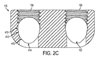
[00105]結婚指輪型の直列デュアル直径連結器110の一実施形態である図2A〜2Cを参照すれば、ロッド受入チャネル122が示される。ロッド受入チャネル122の特有かつ特別な幾何学的形状は、5.5mm直径の脊椎ロッド112および4.75mm直径の脊椎ロッド114の両方をロッド受入チャネル内に固定することを可能にする。ロッド受入チャネル122は、実質的には、3つの円形貫通穴の複合体である。結果として得られるロッド受入チャネル122は、1つの上側の弧410と、2つの中間の弧412と、2つの連結斜面416と、1つの下側の弧414と、から構成される。上側の弧410は、好ましくは、約2.76mmから約3.02mmの半径を有する。たとえば、2.890mmの半径を有する。中間の弧412は、好ましくは、約2.595mmから約2.855mmの半径を有する。たとえば、2.725mmの半径を有する。下側の弧414は、好ましくは、約1.87mmから約2.13mmの半径を有する。たとえば、2.000mmの半径を有する。連結斜面416は、好ましくは、約0.638mmから約0.898mmの長さを有する。たとえば、0.768mmの長さを有する。上側の弧410、中間の弧412、および下側の弧414の中心は、同一線上にある。中間の弧412の中心は、上側の弧410の中心と下側の弧414との間に位置する。上側の弧410および中間の弧412の中心は、好ましくは、約1.00mmから約1.07mmだけ分離される。下側の弧414および中間の弧412の中心は、好ましくは、約1.02mmから約1.09mmだけ分離される。連結斜面416の角度は、好ましくは、上側の弧410、中間の弧412、および下側の弧414の中心によって形成された線から約42°から約44°である。
[00105] Referring to FIGS. 2A-2C, which is an embodiment of a wedding ring type serial
[00106]止めねじ受入ポート124が、ロッド受入チャネル122と位置合わせして配置される。止めねじ受入ポート124は、ねじ式係合によって止めねじ120と係合するように構成される。止めねじ受入ねじ山150は、止めねじ受入ポート124の内面上に配置されて、止めねじ120の外面ねじ山と係合する。止めねじ120は、結婚指輪型の直列デュアル直径連結器110内にねじ込まれ、脊椎ロッド112,114と当接して、脊椎ロッドを結婚指輪型の直列デュアル直径連結器内に固定する。
[00106] A set
[00107]結婚指輪型の直列デュアル直径連結器110の一実施形態では、ロッド受入チャネル起伏126が、各々の止めねじ受入ポート124の反対側に配置される。一実施形態におけるロッド受入チャネルの起伏126は、止めねじ受入ポート124の直径方向に対向する円形の貫通穴である。
[00107] In one embodiment of a wedding ring type serial
[00108]再度図1を参照すれば、脊椎ロッド112,114は、結婚指輪型の直列デュアル直径連結器110と脊椎ロッドとの間の接触面を見ることを可能にするために半透明として示される。5.5mm直径の脊椎ロッド112は、陰付きの領域として区切られた5.5mm接触領域116内で結婚指輪型の直列デュアル直径連結器110と接触する。4.75mm直径の脊椎ロッド114は、第2の陰付きの領域として区切られた4.75mm接触領域118内で結婚指輪型の直列デュアル直径連結器110と接触する。5.5mm接触領域116および4.75mm接触領域118の両方は、それぞれの脊椎ロッド112,114および連結器の接触表面の対向する表面上で鏡映関係にある(図示せず)。
[00108] Referring again to FIG. 1, the
[00109]特定の実施形態では、5.5mm接触領域116は、約32.08mm2であり、4.75mm接触領域118は、約7.44mm2である。これらの接触領域は、ロッド受入チャネル122の開示された実施形態の全範囲の限界値にしたがって変動することができる。
[00109] In certain embodiments, the 5.5
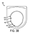
[00110]図3Aおよび図3Bを参照すれば、直列デュアル直径連結器160の上部外形および端部外形のそれぞれが示される。直列デュアル直径連結器160は、結婚指輪型の直列デュアル直径連結器110に関して説明されたのと同じ閉鎖型ロッド受入チャネル122の外形を有する。直列デュアル直径連結器160では、単一の閉鎖型ロッド受入チャネル122が、長手方向軸線全体に沿って通る。この配置は、2本の脊椎ロッド112,114をいかなる横方向の移動も必要とすることなく端と端を接して当接させることを可能にする。
[00110] Referring to FIGS. 3A and 3B, the top and end profiles of series
[00111]図4を参照すれば、ドミノ型の直列デュアル直径連結器180が、上部外形図で示される。ドミノ型の直列デュアル直径連結器180もまた、図2Aおよび図2Cに示された結婚指輪型の直列デュアル直径連結器110の形状に合致する前部外形を有する。ドミノ型の直列デュアル直径連結器180の構成は、隣合わせに配置された2つの直列デュアル直径連結器160の構成である。
[00111] Referring to FIG. 4, a domino-type series
[00112]4本の脊椎ロッド112,114が一緒に固定可能であり、この場合、各々の単一の脊椎ロッドは、4つの単一の止めねじ受入ポート124の各々内に配置された個々の止めねじ120によって固定されることが想定される。また、2本の脊椎ロッド112,114が、各々の脊椎ロッドを固定する2つの止めねじ120によって平行に固定され得ることも想定される。ドミノ型の直列デュアル直径連結器180は、止めねじ受入ポート124の各々において、4.75mm直径の脊椎ロッド114および5.5直径の脊椎ロッド112の任意の組み合わせを固定することができる。非限定的な例には、各々のロッドを固定する2つの止めねじ120で固定された2本の4.75mm直径の脊椎ロッド114と、各々のロッドを固定する2つの止めねじ120を備えた単一の4.75mm直径の脊椎ロッド114および単一の5.5mm直径の脊椎ロッド112と、各々のロッドを固定する1つの止めねじ120で固定された2本の4.75mm直径の脊椎ロッド114および2本の5.5mm直径の脊椎ロッド112と、各々の4.75mm直径の脊椎ロッドを固定する1つの止めねじ120を固定する2つの止めねじ120と5.5mm直径の脊椎ロッド112を固定する1つの止めねじ120とで固定された2本の4.75mm直径の脊椎ロッド114および1本の5.5mm直径の脊椎ロッド112と、各々の5.5mm直径の脊椎ロッドを固定する1つの止めねじ120と4.75mm直径の脊椎ロッドを固定する2つの止めねじ120とで固定された2本の5.5mm直径の脊椎ロッド112および1本の4.75mm直径の脊椎ロッド114と、が含まれる。
[00112] The four
[00113]図5Aおよび図5Bを参照すれば、閉鎖型椎弓板フック210の前部外形図および側部外形図それぞれである。閉鎖型椎弓板フック210は、止めねじ受入ポート124と、閉鎖型ロッド受入チャネル122と、フック刃212と、を備える。フック刃212は、様々な幅および長さのものでよい。
[00113] Referring to FIGS. 5A and 5B, a front profile and a side profile, respectively, of the
[00114]他の標準的なスタイルおよびサイズのフックが想定される。非限定的な例には、閉鎖型および開放型椎弓根フック、閉鎖型椎弓板フック210、開放型椎弓板フック220、開放型胸部フック、開放型オフセット胸部フック、および開放型オフセット腰部フックが含まれる。
[00114] Other standard style and size hooks are envisioned. Non-limiting examples include closed and open pedicle hooks,
[00115]図6を参照すれば、開放型椎弓板フック220の等角図である。開放型椎弓板フック220は、開放型ロッド受入サドル222およびフック刃212を備える。フック刃212は、様々な幅および長さのものでよい。
[00115] Referring to FIG. 6, an isometric view of the open lamina hook 220. FIG. The open lamina hook 220 includes an open
[00116]開放型ロッド受入サドル222は、上側の弧410が存在せず、中間の弧412の一部分もまた存在しなくてよいことを除き、閉鎖型ロッド受入チャネル122と同じ表面形状を備える。一実施形態では、開放型椎弓板フック220の上側のねじ切りされた部分は、当業者に公知の任意の1軸または多軸の脊椎ねじの表面形状を複製することができる。さらに、開放型椎弓板フック220の実施形態では、外部表面形状は、当業者に公知の任意の1軸または多軸の脊椎ねじの外部形状および表面形状を複製することができる。
[00116] The open
[00117]図7Aおよび7Bを参照すれば、固定交差連結器300の上面図および前面図のそれぞれである。固定交差連結器300は、交差連結器ロッドフック322および円錐ねじ302を各端部に備える。円錐ねじ302は、脊椎ロッド112,114をそれぞれの交差連結器ロッドフック322内に保持する。2つの交差連結器ロッドフック322間の距離は、固定交差連結器300をさまざまな横方向間隔で脊椎ロッド112,114に取り付けることを可能にするように変更され得る。選択された実施形態では、2つの交差連結器ロッドフック322の中心間の距離は、約10mmから約40mmの間である。別の選択された実施形態では、2つの交差連結器ロッドフック322の中心間の距離は、約14mmから約36mmの間である。非限定的な例には、約14mm、約16mm、約18mm、約20mm、約22mm、約24mm、約26mm、約28mm、約30mm、約32mm、約34mm、および約36mmの2つの交差連結器ロッドフック322の中心間の距離が含まれる。
[00117] Referring to FIGS. 7A and 7B, a top view and a front view, respectively, of a fixed
[00118]図8を参照すれば、固定交差連結器300の別の実施形態の等角図である。この実施形態では、固定交差連結器300の端部は、固定された交差連結器延長ロッド304によって連結される。固定交差連結器延長ロッド304は、脊椎ロッド112,114に取り付けるように構成された固定交差連結器300をさまざまな横方向間隔で提供するために様々な長さのものになり得る。選択された実施形態では、2つの交差連結器ロッドフック322の中心間の距離は、約10mmから約40mmの間である。別の選択された実施形態では、2つの交差連結器ロッドフック322の中心間の距離は、約14mmから約36mmの間である。非限定的な例には、約14mm、約16mm、約18mm、約20mm、約22mm、約24mm、約26mm、約28mm、約30mm、約32mm、約34mm、および約36mmの2つの交差連結器ロッドフック322の中心間の距離を含む。また、固定交差連結器延長ロッド304は、平行に位置合わせされていない脊椎ロッド112,114に対する固定を可能にするように湾曲しているか、角度付けされていてもよい。円錐ねじ受入ポート324は、脊椎ロッド112,114をそれぞれの交差連結器ロッドフック322内に固定するための円錐ねじ302を受け入れる。
[00118] Referring to FIG. 8, an isometric view of another embodiment of a fixed
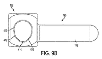
[00119]図9A、図9B、および図9Cを参照すれば、閉鎖型横方向連結器190の前部外形、上部外形、および等角図それぞれである。閉鎖型横方向連結器190は、横方向連結器ロッド192と、止めねじ受入ポート124と、閉鎖型ロッド受入チャネル122と、を備える。横方向連結器190は、多軸ねじ230(図39に示される)または1軸ねじに、横方向連結器ロッド192がねじサドル232内に配置された状態で固着され得る。横方向連結器ロッド192は、標準的な脊椎ロッド112,114に合致するサイズを有している。横方向連結器ロッド192は、好ましくは円形であり、約4.75mmまたは約5.5mmの直径である。また、横方向連結器ロッド192は様々な長さのものでよい。横方向連結器ロッド192は、好ましくは、約15mmから約80mmの長さであり、より好ましくは、約20mmから約60mmの長さである。非限定的な例には、約20mm、約30mm、約40mm、および約60mmの長さを備えた横方向連結器ロッド192が含まれる。
[00119] Referring to FIGS. 9A, 9B, and 9C, there are a front profile, a top profile, and an isometric view, respectively, of the closed
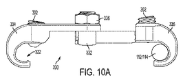
[00120]図10Aを参照すれば、2軸交差連結器330の前部外形図である。2軸交差連結器330は、第1のリンク機構336と、第2のリンク機構334と、枢動支柱332と、中央ナット338と、一対の円錐ねじ302と、を備える。第1のリンク機構336および第2のリンク機構334は、第1の軸線に沿って延びて2軸交差連結器330を長くしている。第1の軸線に沿った長さの調整は、2軸交差連結器330を、連続体に沿って任意の距離で横方向に離間された脊椎ロッド112,114に固着させることを可能にする。これは、脊椎ロッドが有限数の所定の距離の約1つで横方向に離間されなければならない固定交差連結器300とは対照的である。第1のリンク機構336および第2のリンク機構334は、第1の軸線の周りで互いに対して回転することもできる。第1のリンク機構336および第2のリンク機構334の第1の軸線周りの回転は、2軸交差連結器330を、矢状面内で歪曲された脊椎ロッド112,114に固着させることを可能にする。第1のリンク機構336および第2のリンク機構334は、また、第1の軸線に対して垂直な第2の軸線周りで角度付けられる。第1のリンク機構336および第2のリンク機構334の第2の軸線周りの角度付けは、2軸交差連結器330を、前頭面内で歪曲された脊椎ロッド112,114に固着させることを可能にする。
[00120] Referring to FIG. 10A, a front view of a
[00121]2軸交差連結器330の第1の軸線に沿った長さの調整は、2軸交差連結器330を、所定範囲内の連続体に沿って任意の距離で横方向に離間された脊椎ロッド112,114に固着させることを可能にする。
[00121] The adjustment of the length along the first axis of the biaxial cross-connector 330 caused the biaxial cross-connector 330 to be laterally spaced at any distance along the continuum within a predetermined range. It is possible to fix to the
[00122]図11Aおよび11Bを参照すれば、第1のリンク機構336は、交差連結器ロッドフック322と、2軸交差連結器延長ロッド342と、2軸交差連結器延長ロッドリミッタ344と、を備える。交差連結器ロッドフック322は、上側の弧410が存在せず、中間の弧412の一部分もまた存在しなくてよいことを除き、閉鎖型ロッド受入チャネル122と同じ外形を備える。2軸交差連結器延長ロッド342は、その端部上に配置された2軸交差連結器延長ロッドリミッタ344を備えた丸いシャフトである。2軸交差連結器延長ロッドリミッタ344は、2軸交差連結器330の操作中に2軸交差連結器延長ロッド342が枢動支柱332から係合解除されることを防止するのに役立つ。2軸交差連結器延長ロッド342は、好ましくは、約10mmから約40mmの長さであり、より好ましくは、約17mmから約32mmの長さである。2軸交差連結器延長ロッド342は、好ましくは、約3.5mmから約4.5mmの直径であり、より好ましくは、約3.9mmから約4.1mmの直径である。たとえば、2軸交差連結器延長ロッド342は、24mmの長さおよび3.98mmの直径であってもよい。
[00122] Referring to FIGS. 11A and 11B, the
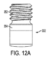
[00123]図12Aおよび図12Bを参照すれば、枢動支柱332の側部外形および前部外形それぞれである。枢動支柱332は、2軸交差連結器延長ロッドチャネル350と、ねじ切りされた支柱352と、リンク機構保持肩部354と、を備える。2軸交差連結器延長ロッドチャネル350は、2軸交差連結器延長ロッドが第1の面356と接触するときに、2軸交差連結器延長ロッド342および2軸交差連結器延長ロッドリミッタ344が妨害無く通り抜けることを可能にするように構成される。それとは反対に、2軸交差連結器延長ロッドチャネル350は、2軸交差連結器延長ロッドが第2の面358と接触するときに、2軸交差連結器延長ロッド342および2軸交差連結器延長ロッドリミッタ344が妨害無く通り抜けることを防止するように構成される。これは、2軸交差連結器延長ロッドリミッタが枢動支柱332上にひっかかるからである。ねじ切りされた支柱352は、中央ナット338上の内部ねじ山と係合するように構成されたねじ山を備える。
[00123] Referring to FIGS. 12A and 12B, the side profile and the front profile of the
[00124]枢動支柱332の2軸交差連結器延長ロッドチャネル350の第1の面356は、好ましくは、2軸交差連結器延長ロッド342の直径より約0.6から約1.4mm大きい直径を有する弧である。枢動支柱332の2軸交差連結器延長ロッドチャネル350の第2の面358は、好ましくは、2軸交差連結器延長ロッド342の直径より約0.03から約0.30mm大きい直径を有する弧である。たとえば、前述の例では、2軸交差連結器延長ロッド342は、3.98mmの直径でもよく、第1の面356の弧の直径は、4.98mmでもよく、第2の表面358の直径は、4.02mmでもよい。
[00124] The
[00125]図13Aおよび図13Bを参照すれば、第2のリンク機構334の前部外形図および上部外形図それぞれである。第2のリンク機構334は、交差連結器ロッドフック322と、円錐ねじ受入ねじ山326を有する円錐ねじ受入ポート324と、リンク機構保持オリフィス340を有する2軸交差連結器延長板346と、を備える。リンク機構保持オリフィス340は、枢動支柱332のリンク機構保持肩部354と係合する。2軸交差連結器延長板346は、円錐ねじ受入ポート324および交差連結器ロッドフック322から離れる方向に延びる平坦な細長片である。2軸交差連結器延長板346は、好ましくは、約10mmから約40mmの長さであり、より好ましくは、約17mmから約32mmの長さである。2軸交差連結器延長板346の長さは、第2のリンク機構334の薄くされた部分の長さである。たとえば、2軸交差連結器延長板346は、約17mmの長さ、約18mmの長さ、約20mmの長さ、約24mmの長さ、および約32mmの長さであってもよい。
[00125] Referring to FIGS. 13A and 13B, a front outline view and a top outline view of the
[00126]組み立てられたとき、中央ナット338は、第2のリンク機構334をリンク機構保持肩部354に向かって押圧し、リンク機構保持肩部354は、第2のリンク機構を、2軸交差連結器延長ロッドのチャネル350に通される2軸交差連結器延長ロッド342内に押圧する。中央ナット338の圧縮力は、摩擦力と併せて、2軸交差連結器330が第1の軸線に沿って延び、第1の軸線周りで回転し、または第2の軸線周りで角度を付けることを防止する。
[00126] When assembled, the central nut 338 presses the
[00127]再度図10Aを参照すれば、延長された構成における2軸交差連結器330の前部外形図である。2軸交差連結器330は、5.5mm直径の脊椎ロッド112および4.75mm直径の脊椎ロッド114の両方を固定することができる。5.5mm直径の脊椎ロッド112は、円錐ねじ302が完全には前進されずに脊椎ロッドが交差連結器ロッドフックに押し込まれていない非固定構成で、交差連結器ロッドフック322内にあるように図10Aに示される。
[00127] Referring again to FIG. 10A, a front outline view of the
[00128]図10Bを参照すれば、後退された構成の2軸交差連結器330の上部外形である。円錐ねじ302は、ヘックスローブ内部駆動機構を有する。
[00128] Referring to FIG. 10B, a top view of a
[00129]2軸交差連結器330の一実施形態では、2軸交差連結器延長ロッド342および2軸交差連結器延長板346の異なる長さによって与えられる調整の範囲は、2軸交差連結器330が、交差連結器ロッドフック322内に配置された脊椎ロッド112/114の中心線間の間隔を約30mmから約70mmまでに調整されることを可能にする。2軸交差連結器330の一実施形態では、交差連結器ロッドフック322内に配置された脊椎ロッド112/114の中心線間の間隔は、約34mmから約37mmまでに調整され得る。2軸交差連結器330の別の実施形態では、交差連結器ロッドフック322内に配置された脊椎ロッド112/114の中心線間の間隔は、約35mmから約39mmまでに調整され得る。2軸交差連結器330の別の実施形態では、交差連結器ロッドフック322内に配置された脊椎ロッド112/114の中心線間の間隔は、約37mmから約43mmまでに調整され得る。2軸交差連結器330の別の実施形態では、交差連結器ロッドフック322内に配置された脊椎ロッド112/114の中心線間の間隔は、約41mmから約51mmまでに調整され得る。2軸交差連結器330の別の実施形態では、交差連結器ロッドフック322内に配置された脊椎ロッド112/114の中心線間の間隔は、約49mmから約67mmまでに調整され得る。2軸交差連結器330の詳細に開示された複数の実施形態の組み合わせは、2軸交差連結器330が、脊椎ロッド112/114を約34mmから約67mmまでの連続体に沿って任意の場所に離間されて固定するのに適するように選択されることを可能にする。
[00129] In one embodiment of the two-
[00130]図14Aを参照すれば、2軸交差連結器330の一実施形態である。2軸交差連結器330は、第1のリンク機構336と、第2のリンク機構334と、中央係止支柱370と、中央係止ねじ339と、一対の円錐ねじ302と、を備える。第1のリンク機構336および第2のリンク機構334は、第1の軸線に沿って延びて2軸交差連結器330を長くすることができる。第1の軸線に沿った長さの調整は、2軸交差連結器330を、連続体に沿って任意の距離だけ横方向に離間された脊椎ロッド112,114に固着させることを可能にする。これは、脊椎ロッドが有限数の所定距離の約1で横方向に離間されなければならない固定交差連結器300と対照的である。第1のリンク機構336および第2のリンク機構334は、第1の軸線の周りで互いに対して回転することもできる。第1のリンク機構336および第2のリンク機構334の第1の軸線周りの回転は、2軸交差連結器330を、矢状面内で歪曲された脊椎ロッド112,114に固着させることを可能にする。第1のリンク機構336および第2のリンク機構334は、また、第1の軸線に対して垂直な第2の軸線周りで角度付けられる。第1のリンク機構336および第2のリンク機構334の第2の軸線周りの角度付けは、2軸交差連結器330を、前頭面内で歪曲された脊椎ロッド112,114に固着させることを可能にする。
[00130] Referring to FIG. 14A, one embodiment of a two-
[00131]図14Aおよび14Bを参照すれば、第1のリンク機構336は、交差連結器ロッドフック322と、2軸交差連結器延長ロッド342と、2軸交差連結器延長ロッドリミッタ344と、を備える。交差連結器ロッドフック322は、上側の弧410が存在せず、中間の弧412の一部分もまた存在しなくてよいことを除き、閉鎖型ロッド受入チャネル122と同じ外形を備える。2軸交差連結器延長ロッド342は、端部上に配置された2軸交差連結器延長ロッドリミッタ344を備えた丸いシャフトである。一実施形態では、2軸交差連結器延長ロッドリミッタ344は、2軸交差連結器延長ロッド342の直径を超えて突出するピンである。2軸交差連結器延長ロッドリミッタ344は、2軸交差連結器延長ロッド342が、2軸交差連結器330の操作中に中央係止支柱370から係合解除されることを防止するのに役立つ。2軸交差連結器延長ロッドリミッタ344は、好ましくは、製造および組み立てのプロセス中に、中央係止支柱370を通した後で2軸交差連結器延長ロッド342に取り付けられる。2軸交差連結器延長ロッドリミッタ344は、好ましくは、2軸交差連結器延長ロッド342を中央係止支柱370から取り外しできないようなサイズを有している。
[00131] Referring to FIGS. 14A and 14B, the
[00132]図15を参照すれば、図14A〜14Cに示される2軸交差連結器330の実施形態で使用される中央係止支柱370の一実施形態が示される。中央係止支柱370は、2軸交差連結器延長ロッド通路374と、ねじ切りされた係止ねじ受入部376と、係止支柱保持フランジ372と、を備える。2軸交差連結器延長ロッド通路374は、2軸連結器延長ロッド342が妨害無く通り抜けるが、2軸交差連結器延長ロッドリミッタ344が通り抜けることは防止されることを可能にするように構成される。ねじ切りされた係止ねじ受入部376は、中央係止ねじ339上の外面ねじ山と係合するように構成された内部ねじ山を備える。係止支柱保持フランジ372は、中央係止支柱370を、中央係止ねじで固定する前に第2のリンク機構内に保持する。
[00132] Referring to FIG. 15, one embodiment of a
[00133]第2のリンク機構334は、交差連結器ロッドフック322と、円錐ねじ受入ねじ山326を有する円錐ねじ受入ポート324と、リンク機構保持オリフィス340を有する2軸交差連結器延長板346と、を備える。リンク機構保持オリフィス340は、リンク機構保持オリフィス340の表面のまわりに配置されたリンク機構フランジ378を有する。リンク機構保持フランジ378は、係止支柱保持フランジ372と係合する。
[00133] The
[00134]組み立てられたとき、中央係止ねじ339は、中央係止支柱370を上方向に引っ張る。中央係止支柱370の移動は、第1のリンク機構336も同様に上方向に移動させ、第1のリンク機構336を第2のリンク機構334に対して圧縮する。摩擦力と併用した、第2のリンク機構334および第1のリンク機構336を一緒に引っ張る中央係止ねじ339および中央係止支柱370の圧縮力は、2軸交差連結器330が、第1の軸線に沿って延びること、第1の軸線周りで回転すること、または、第2の軸線周りで角度を付けられることを防止する。
[00134] When assembled, the
[00135]図39を参照すれば、多軸ねじ230の前部外形である。多軸ねじ230は、脊椎ロッド112,114またはたとえば横方向の連結器ロッド192を受け入れるためのねじサドル232を備える。ねじサドル232のロッド受け入れ幾何学的形状は、5.5mm直径の脊椎ロッド112または4.75mm直径の脊椎ロッド114を含む複数の直径の脊椎ロッドを受け入れるために、開放型椎弓板フック220の開放型受入サドル222のロッド受入幾何学的形状と合致するように構成されることが想定される。複数の直径の脊椎ロッド112,114を固定するための類似のロッド受入幾何学的形状を備えた1軸ねじもまた想定される。
[00135] Referring to FIG. 39, the front profile of the
[00136]本開示を通して、デュアル直径連結器、デュアル直径フック、およびデュアル直径ねじに参照がなされてきたが、2つの直径のロッドを受け入れることを可能にするために使用される技術は、3つまたはそれ以上の直径のロッドを可能にするように改変され得る。 [00136] Throughout this disclosure, references have been made to dual diameter couplers, dual diameter hooks, and dual diameter screws, but three techniques have been used to allow two diameter rods to be received. Or it can be modified to allow for larger diameter rods.
[00137]図16A〜16Cを参照すれば、ロッド低減装置600が示される。図16Cは、断面線N−Nに沿って得られる低減装置600の長手方向の断面図である。図示される例示的な実施形態では、低減装置600は、ハウジング管501と、前進ノブ502と、低減ロッド503と、キャップ504と、内側管505と、後退スリーブ506と、低減スリーブ507と、解放リング508と、解放リングねじ509と、指部510と、指部ばね511と、ばねヒンジピン513と、指部カムピン514と、指部ヒンジピン515と、溶接スリーブ516と、解放ばね517と、複数の転がり軸受518と、指部カバー519と、を備える。一緒に組み立てられたとき、これらの構成要素は低減装置600を形成し、この低減装置600は、第1の端部602および第2の端部604を有する中空の円筒形状のアセンブリを備える。第1の端部602は、第1のアセンブリ開口部606を備え、第2の端部604は、第2のアセンブリ開口部608を備える。上記で記載された構成要素の各々は、本明細書において以下で個々に説明され、別個の図に示される。さらに、低減装置600の構成要素の各々が、どのようにして相互連結されるか、および、組み立てられた後に低減装置600が作動においてどのように作用するかが以下の本明細書において示され説明される。
[00137] Referring to FIGS. 16A-16C, a
[00138]図17A〜17Cを参照すれば、低減装置600のハウジング管501が示される。ハウジング管501は、中空のハウジング管本体520を備える。ハウジング管本体520は、ハウジング管第1端部522と、ハウジング管第1端部522とは反対側のハウジング管第2端部524と、を有する。ハウジング管第1端部522は、成形される。この例では、ハウジング管第1端部522は、六角形状を有する。さらに、この例では、ハウジング管第1端部522は、ハウジング管係合細長穴521を有する。また、ハウジング管第1端部522は、ハウジング管内部ねじ山525も備える。また、ハウジング管第1端部522は、第1のハウジング管開口部616を備え、第2の端部524は、第2のハウジング管開口部618を備える。ハウジング管本体520は、第1および第2の外側の管開口部616/618をそれぞれ接続する内部ハウジング管チャネル619を備える。ハウジング管本体520は、第2端部524のところに、直径方向に対向する2つのハウジング管細長穴526を有し、この細長穴526の各々は、第2端部524からハウジング管本体520の少なくとも一部分に沿って長手方向に延在する。ハウジング管細長穴526は、さらに、幅広部分528に連結された幅狭部分527を備える。
[00138] Referring to FIGS. 17A-17C, the
[00139] また、ハウジング管本体520は、第2の端部524のところにハウジング管細長穴526から円周方向に90°ずらされて配置された、直径方向に対向する第2のハウジング管細長穴529を備える。第2のハウジング管細長穴529は、第2端部524からハウジング管本体520の少なくとも一部分に沿って長手方向に延在する。任意ではあるが、ハウジング管本体520は、ハウジング管本体520の表面内にエッチングされた中型のダイヤモンド刻み523などの把持部位を備える。
[00139] Also, the housing tube
[00140]図18Aおよび18Bを参照すれば、低減装置600の前進ノブ502が示される。前進ノブ502は、中空の前進ノブ本体530を備える。前進ノブ本体530は、前進ノブ第1端部532と、前進ノブ第1端部532の反対側の前進ノブ第2端部534と、を有する。前進ノブ第1端部532は、成形される。この例では、前進ノブ第1端部532は、六角形状を有する。前進ノブ本体530は、そこから延びるとともに前進ノブ本体530の中点と前進ノブ第1端部532との間に配置された前進ノブ環状リング538も備える。前進ノブ本体530は、その内面の一部分に前進ノブ内部ねじ切り部531を備える。この例では、前進ノブ内部ねじ切り部531は、前進ノブ第2端部534から前進ノブ本体530の中点をちょうど超えたところまで前進ノブ本体530の内面に沿って配置される。前進ノブ環状リング538は、さらに、前進ノブ環状リング538内で前進ノブ本体530の円周の周りに環状式に配置された前進ノブ支承ウェル539を備える。前進ノブ第1端部532は、第1の前進ノブ開口部626も備え、前進ノブ第2端部534は、第2の前進ノブ開口部628を備える。前進ノブ本体530は、第1および第2のノブ開口部626/628をそれぞれ接続する前進ノブ内部チャネル629を備える。
[00140] Referring to FIGS. 18A and 18B, the
[00141]図19Aおよび19Bを参照すれば、低減装置600の低減ロッド503が示される。低減ロッド503は、第1の低減ロッド端部542と、第1の低減ロッド端部542とは反対側の第2の低減ロッド端部544と、を有する中空の円筒形状の低減ロッド本体540を備える。第1の低減ロッド端部542は、第1の低減ロッド開口部543を備え、第2の低減ロッド端部544は、第2の低減ロッド開口部545を備える。低減ロッド本体540は、第1および第2の低減ロッド開口部543/545をそれぞれ接続する低減ロッド内部チャネル547を備える。第1の低減ロッド端部542は、低減ロッド本体540の外面の一部分に配置された低減ロッド外面ねじ山541を備える。第1の拡張部548aが、第2の低減ロッド端部544に隣接する低減ロッド本体540の外面から径方向に延びる。第2の拡張部548bは、第2の低減ロッド端部544に隣接するとともに第1の拡張部548aに対して直径方向に対向する低減ロッド本体540の外面から径方向に延びる。低減ロッド本体540は、低減ロッド本体540の中点に隣接して、第2の低減ロッド端部544側に配置された環状の球根状部分546も備える。環状の球根状部分546は、低減ロッド本体540の残りの部分と比較して増大した外径を有する。
[00141] Referring to FIGS. 19A and 19B, a
[00142]図20を参照すれば、低減装置600のキャップ504が示される。キャップ504は、第1のキャップ端部552と、第1のキャップ端部552とは反対側の第2のキャップ端部554と、を有する中空の円筒形状のキャップ本体550を備える。第1のキャップ端部552は、第1のキャップ開口部556を備え、第2のキャップ端部554は、第2のキャップ開口部558を備え、キャップ本体550は、第1のキャップ開口部556を第2のキャップ開口部558に接続するキャップ内部チャネル557を備える。また、第2のキャップ端部554は、キャップ本体550の外面に配置されたキャップ外面ねじ山551と、キャップ支承ウェル555を形成するように第2のキャップ開口部558の周りに配置された実質的に半球状のチャネルと、を備える。
[00142] Referring to FIG. 20, the
[00143]図21A〜21Dを参照すれば、低減装置600の内側管505が示される。内側管505は、第1の内側管端部562と、第1の内側管端部562とは反対側の第2の内側管端部564と、を有する中空の円筒形状の内側管本体560を備える。第1の内側管端部562は、第1の内側管開口部566を備え、第2の内側管端部564は、第2の内側管開口部568を備える。内側管本体560は、第1および第2の内側管開口部566/568をそれぞれ接続するロッド内部チャネル567を備える。図21Aおよび図21Cに示されるように、内側管505は、第1の内側管細長穴565aと、第1の内側管細長穴565aと直径方向に対向する第2の内側管細長穴565bと、を備える。内側管本体560は、図21Bに示されるように、第1の内側管チャネル569aおよび第2の内側管チャネル569bも備える。内側管本体560は、指部510を受け入れるためにその中に配置された、第1の指部細長穴561aと、第1の指部細長穴561aと直径方向に対向する第2の指部細長穴561bと、を備える。
[00143] Referring to FIGS. 21A-21D, the
[00144]また、第1の左ばねポケット906aおよび第1の右ばねポケット904aが、指部ばね511を受け入れるために、内側管本体560内で、第1の指部細長穴561aに隣接してその両側に配置される。同様に、第2の左ばねポケット906bおよび第2の右ばねポケット904bが、指部ばね511を受け入れるために、内側管本体560内で、第2の指部細長穴561bに隣接してその両側に配置される。さらに、内側管本体560は、指部ヒンジピン515を受け入れるための指部ピン開口900と、ばねヒンジピン513を受け入れるためのばねピン開口902と、を備える。
[00144] Also, a first
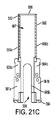
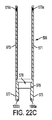
[00145]図22A〜22Cを参照すれば、低減装置600の後退スリーブ506が示される。後退スリーブ506は、第1の後退スリーブ端部572と、第1の後退スリーブ端部572とは反対側の第2の後退スリーブ端部574と、を有する中空の円筒形状の後退スリーブ本体570を備える。後退スリーブ506は、さらに、後退スリーブ本体570の第1の後退スリーブ端部572から離れる方向に長手方向に延びる第1の後退スリーブ腕部571と、第1の後退スリーブ端部572から離れる方向に、第1の後退スリーブ腕部571とは直径方向に対向して後退スリーブ本体570に沿って長手方向に延びる第2の後退スリーブ腕部573と、を備える。さらに、後退スリーブ506は、後退スリーブ本体570の第2の後退スリーブ端部574から離れる方向に長手方向に延びる第3の後退スリーブ腕部575と、第2の後退スリーブ端部574から離れる方向に、第3の後退スリーブ腕部575とは直径方向に対向して後退スリーブ本体570に沿って長手方向に延びる第4の後退スリーブ腕部577と、を備える。さらに、解放ばね支持リング578が、第1の後退スリーブ端部572と第2の後退スリーブ端部574との間の、後退スリーブ本体570の内表面の周りに配置されたリップ部によって形成される。解放ばね支持リング578は、組み立て時に解放ばね517と当接し、解放ばねの並進を防止する。
[00145] Referring to FIGS. 22A-22C, a retracting
[00146]図23を参照すれば、低減装置600の低減スリーブ507が示される。低減スリーブ507は、第1の低減スリーブ端部582と、第1の低減スリーブ端部582とは反対側の第2の低減スリーブ端部584と、を有する中空の円筒形状の低減スリーブ本体580を備える。第1の低減スリーブ端部582は、第1の低減スリーブ開口部586を備え、第2の低減スリーブ端部584は、第2の低減スリーブ開口部588を備える。低減スリーブ本体580は、第1および第2の低減スリーブ開口部586および588をそれぞれ接続する低減スリーブ内部チャネル587を備える。図に示されるように、低減スリーブ507は、第1の低減スリーブ端部582から低減スリーブ本体580の一部分に沿って長手方向に延在する低減ロッド係合細長穴581を備える。低減スリーブ本体580に沿って互いに直径方向に対向して配置された2つの低減ロッド係合細長穴581が存在することが、一実施形態において想定される。
[00146] Referring to FIG. 23, a
[00147]低減スリーブ本体580の、低減ロッド係合細長穴581と同じ側に沿って、低減スリーブ観察開口583が、第2の低減スリーブ端部584に隣接して、および/または、その近傍に配置される。また、低減スリーブ本体580は、その中に、第2の低減スリーブ端部584の先端に配置されたロッド係合半径部585と、その中に、第2の低減スリーブ端部584の先端に配置された別のロッド係合半径部585と、を備える。低減スリーブ本体580は、さらに、その中に、第2の低減スリーブ端部584の先端に、ロッド係合半径部585から90°ずらして配置された低減スリーブ径方向低減部589を備える。
[00147] Along the same side of the
[00148]図24Aおよび図24Bを参照すれば、低減装置600の解放リング508が示される。解放リング508は、第1の解放リング端部592と、第1の解放リング端部592とは反対側の第2の解放リング端部594と、を有する中空の円筒形状の解放リング本体590を備える。第1の解放リング端部592は、第1の解放リング開口部596を備え、第2の解放リング端部594は、第2の解放リング開口部598を備える。解放リング本体590は、第1および第2の解放リング開口部596/598をそれぞれ接続する解放リング内部チャネル597を備える。さらに、解放リング508は、解放リング本体590内で解放リング本体590の円周の周りに配置された第1の解放リング構成591と、解放リング本体590内で解放リング本体590の円周の周りに第1の解放リング特徴591に隣接して配置された第2の解放リング特徴593と、を備えることができる。また、解放リング508は、解放リングねじ509を受け入れるために、解放リング本体590内に配置された少なくとも1つの解放リングねじ開口595を備えることができる。一実施形態では、解放リング508は、解放リングねじ509を受け入れるための、直径方向に対向する2つの解放リングねじ開口595を備える。
[00148] Referring to FIGS. 24A and 24B, a
[00149]図16Cに戻って参照すれば、低減装置600は、互いに直径方向に対向する2つの指部510を備える。次に図25A〜25Dを参照すれば、指部510は、指部第1端部662と、指部第1端部662とは反対側の指部第2端部664と、を有する指部本体660を備える。指部第2端部664は、指部フック切下部663を有する指部フック661を備える。1つの例では、指部フック切下部663は、鋭角を上回る任意の角度αを有することができる。別の例では、指部フック切下部663は、約20°から約90°まで、約30°から約80°まで、約45°から約75°までの角度αを含むことができる。さらに他の例では、指部フック切下部663は、約40°、約50°、約60°、約70°、約80°、または約90°未満の角度αを含むことができる。
[00149] Referring back to FIG. 16C, the
[00150]指部本体660は、そこを貫通して配置された指部開口665を備える。指部本体660は、また、指部本体660から長手方向に延びる第1の指部延長部670と、指部本体660から長手方向に、第1の指部延長部670とは反対側にそこから離間して延びる第2の指部延長部672と、を備える。第1の指部延長部670は、指部本体660から交差方向に延びる指部第1端部662に配置された第1の指部停止部676を備える。第2の指部延長部672は、指部本体660から交差方向に延びる指部第1端部662に配置された第2の指部停止部678を備える。
[00150]
[00151]図25A〜25Cと共に図25Dを詳細に参照すれば、第1および第2の指部延長部670,672のそれぞれは、指部細長穴680を備える。指部細長穴680は、3つの領域、すなわち、第1の領域Aと移行領域Bと第3の領域Cとを備える。特に、細長穴の第1の領域Aは、指部カムピン514が第1の領域A内に配置されたときに、指部カムピン514が第1の領域A内で進行・摺動嵌合を形成するように構成されるとともに、そのようなサイズに形成される幅を備えている。一例として、第1の領域Aの幅は、上側細長穴ガイド682および下側細長穴ガイド684によって形成され、指部カムピン514が第1の領域A内で摺動するのを可能にするのには十分であるが、第1の領域A内の指部カムピン514の摺動移動に対して交差する実質的横方向の移動には不十分なものである。実質的横方向の移動は、指部カムピン514の直径の10分の1を上回る移動として定義される。指部細長穴680の第3の領域Cは、これが指部カムピン514との隙間嵌めを形成する幅を有するように構成されるとともに、そのようなサイズに形成される。一例として、第3の領域Cは、その形状およびサイズが、第1の領域の幅から第3の領域Cの最大幅までの円滑な移行を作り出すようなじょうご形状を有するように構成される。移行領域Bは、第1の領域Aの幅(すなわち、進行・摺動嵌合)から第3の領域Cの幅(すなわち、隙間嵌め)までの円滑な移行をもたらす。作動においては、指部カムピン514は、これらが、指部細長穴680のそれぞれの指部カム内面688に沿って係合し、延在するように指部細長穴680内に配置される。この作用は、本明細書の以下においてより詳細に説明される。
[00151] Referring to FIG. 25D in detail in conjunction with FIGS. 25A-25C, each of the first and
[00152]したがって、指部510が、ばね付勢された径方向内側の位置(すなわち、通常位置)にあるときには、指部カムピン514は、指部カム686によって形成された第3の領域C内に配置される。低減装置600が、第2のアセンブリ開口部608が多軸ねじ230または1軸椎弓根ねじのチューリップ型頭部上で摺動されるように移動されるときに、チューリップ型頭部は、第2のアセンブリ開口部608内に挿入されたときに指部510の指部フック661と係合し、これらを指部ばね511の力に抗って外方向に強制および/または押し出す。指部510が外方向に押し出されると、指部は、指部ヒンジピン515周りで摺動し、それにより、指部第1端部662は、径方向内側に移動して、指部カムピン514(これは、第3の領域C内に依然として配置され、それぞれの指部カム内側表面688に係合される)を、第3の領域C内でのそれぞれの指部カム内側表面688との係合から上向きに離し、任意ではあるが、それぞれの指部カム外側表面689に係合させる。第3の領域Cの隙間嵌めは、椎弓根ねじ230のチューリップ型頭部がロッド低減装置600の第2のアセンブリ開口部608内に挿入されることを可能にするために、指部510がロッド低減装置600内で枢動することを可能にする隙間をもたらす。
[00152] Accordingly, when the
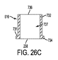
[00153]図26A〜26Dを参照すれば、溶接スリーブ516が示される。溶接スリーブ516は、第1の溶接スリーブ端部732と、第2の溶接スリーブ端部734と、を有する中空の円筒形状の溶接スリーブ本体730を備える。本体は、第1の溶接スリーブ端部732に配置された、第1の溶接スリーブ開口部736と、第2の溶接スリーブ開口部738と、2つの開口部を接続する溶接スリーブ内部チャネル737と、を備える。溶接スリーブ本体730は、直径方向に対向する後退スリーブ腕部係合細長穴733を備える。第2の溶接スリーブ端部734は、溶接スリーブフランジ731を備える。
[00153] Referring to FIGS. 26A-26D, a
[00154]図27を参照すれば、低減装置600の指部カバー519が示される。指部カバー519は、指部カバー本体750を有する。指部カバー本体750は、指部カバー開口752を備え、他の構成要素の1つまたは複数の湾曲にぴったりと合致するように湾曲される。
[00154] Referring to FIG. 27, a
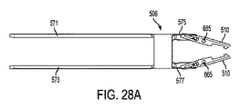
[00155]図28A〜30Aおよび先に参照されたすべての図を参照すれば、ロッド低減装置600のアセンブリが説明される。図28Aおよび28Bに示されるように、指部510の第1および第2の指部延長部670,672は、後退スリーブ506の第3の後退スリーブ腕部575の周りに挿入される。指部カムピン514は、第1の指部延長部670の指部細長穴680と、第3の後退スリーブ腕部575内に配置された第3の後退スリーブ腕部交差ピン開口1000aと、を通り、さらに、第2の指部延長部672の指部細長穴680を通って挿入される。同様に、指部510の第1および第2の指部延長部670,672は、後退スリーブ506の第4の後退スリーブ腕部577の周りに挿入される。指部カムピン514は、ここでも、第2の指部延長部672の指部細長穴680と、第4の後退スリーブ腕部577内に配置された第4の後退スリーブ腕部交差ピン開口1000bと、を通り、さらに、第2の指部延長部672の指部細長穴680を通って挿入される。
[00155] Referring to FIGS. 28A-30A and all previously referenced figures, the assembly of the
[00156]図29Aおよび29Bを参照すれば、後退スリーブ506と指部510とのアセンブリは、内側管本体560の第2の内側管端部564の上方に挿入され、それにより、指部510は、第1および第2の指部細長穴561a/561b内へと摺動する。次に、一例として、指部ばね511が、第1の左ばねポケット906aおよび第1の右ばねポケット904a内に配置される。指部ばね511の一方の端部は、第1の右ばねポケット904aの表面に当接され、指部ばね511の反対側の端部は、第1の指部停止部676に当接される。指部ばね511の一方の端部は、第1の左ばねポケット906aの表面に当接され、指部ばね511の反対側の端部は、第2の指部停止部678に当接される。指部ばね511は、ばねピン開口902と位置合わせされ、次いで、ばねヒンジピン513が、位置合わせされたそれぞれのばねピン開口902およびばねコイル内に圧入される。また、指部開口665は、ばねピン開口900と位置合わせされ、次いで、指部ヒンジピン515は、そのように位置合わせされた開口内にそこを通って圧入される。同じ組み立ては、第2の指部510に対して実施される。組み立てられた後、ピンは、レーザ溶接プロセスなどの従来の溶接プロセスを用いて所定場所に溶接される。ピン端部は、次いで、内側管505の外面と同一平面になるように研磨される。
[00156] Referring to FIGS. 29A and 29B, the
[00157]そのような構成では、指部ばね511は、指部510を、低減装置600の中央長手方向軸線に向かって径方向内側に付勢し、それにより、指部510の指部フック切下部663は、チューリップ型頭部234内のその両側に配置されたチューリップ型頭部ポケット236と係合する。チューリップ型頭部ポケット236は、たとえば図32Bに示されるように、指部フック切下部163に対応し、これと係合するそれぞれのチューリップ型頭部切下部238を備える。
[00157] In such a configuration, the
[00158]解放ばね517は、図29Bに示されるように、内側管505の内側管本体560の第2の内側管端部564の上方で摺動される。次に、溶接スリーブ516の後退スリーブ腕部係合細長穴733を、後退スリーブ506のそれぞれの第1および第2の腕部571/573に位置合わせし、次いで、溶接スリーブ516の溶接スリーブフランジ731が図29Aおよび図29Bに示されるように後退スリーブ本体570と同一平面になるまで、溶接スリーブ516を内側管本体560の第2の内側管端部564の上方で摺動させる。指部カバー本体750は、図29Aおよび図29Bに示されるようにそれぞれの第1および第2の指部細長穴561a/561b内に嵌合され、次いで、たとえば溶接(たとえば指部カバーの表面周りのレーザ溶接)、スナップ嵌合などの任意の数の従来の手段において内側管本体560に連結され得る。
[00158]
[00159]図16A〜16Cおよび530を参照すれば、解放リング508は、ハウジング管501の上方で摺動される。低減ロッド503は、図30に示されるようにハウジング管501内に挿入され、それにより、低減ロッド503の第1および第2の拡張部548a/548bは、ハウジング管501のハウジング管細長穴526を通って挿入されそこから延びる。次に、図29Aおよび図29Bに示された後退スリーブ506/内側管505/溶接スリーブ516/指部510のアセンブリが、ハウジング管501の第2の端部524内に挿入され、それにより、後退スリーブ506の第1および第2の腕部571/573は、図30に示されるようにハウジング管501の第2のハウジング管細長穴529と整合し、その中へと摺動する。溶接スリーブ516は、溶接を含む従来の連結方法によってハウジング管501に連結される。さらに、第1および第2のねじ509a/509bが、解放リング508、ハウジング管501、およびそれぞれの第1および第2の後退スリーブ腕部571/573を通って挿入され、これらとねじ式に係合される。第1の後退スリーブ腕部571と第2の後退スリーブ腕部573との係合は、第1の後退スリーブ腕部ねじ開口579aおよび第2の後退スリーブ腕部ねじ開口579bのそれぞれを介する。
[00159] Referring to FIGS. 16A-16C and 530, the
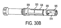
[00160]図30A〜30Cを参照すれば、低減装置600の最終アセンブリが示される。詳細には、低減スリーブ507は、ハウジング管501の第2の端部524の上方で摺動され、それにより、低減ロッド係合細長穴581は、低減ロッド503の第1および第2の拡張部548a,548bと当接し、これに溶接される。前進ノブ502は、ハウジング管501のハウジング管第1端部522内に挿入され、複数の転がり軸受518が、前進ノブ502の前進ノブ環状リング538の前進ノブ支承ウェル539内に配置され、次いで、キャップ504が、ハウジング管501のハウジング管の第1の端部522にねじ式に係合される。キャップの支承ウェル555は、前進ノブ支承ウェル539の反対側で転がり軸受518と接面する。
[00160] Referring to FIGS. 30A-30C, the final assembly of the
[00161]図33Aおよび図33Bを参照すれば、低減アダプタ1100が示される。低減アダプタ1100は、第1の端部のところの内側六角頭部(たとえばソケット頭部に類似する)と、第1の端部とは反対側の第2の端部のところの外側六角端部と、を備える。頭部の他のタイプ、構成および形状が使用され得ることが理解される。第1の端部は、図33Aおよび33Bに示されるように、前進ノブ502の前進ノブ第1端部532上に挿入されて前進ノブ502の前進ノブ係合頭部536と係合することができる。
[00161] Referring to FIGS. 33A and 33B, a reduction adapter 1100 is shown. Reduction adapter 1100 includes an inner hexagonal head at a first end (eg, similar to a socket head) and an outer hexagonal end at a second end opposite the first end. And comprising. It is understood that other types, configurations and shapes of the head can be used. The first end may be inserted over the advance knob
[00162]図40A〜40C、椎弓根ねじ230の実施形態を参照すれば、椎弓根ねじ230および低減装置600の第2のアセンブリ開口部608のサイズおよび形状は、実質的に合致する。椎弓根ねじ230のチューリップ型頭部214が、装置600の第2の端部604の第2のアセンブリ開口部608内に挿入されるとき、椎弓根ねじ230は、最少の運動自由度を有して係合される。したがって、1つの実施形態では、椎弓根ねじ230のチューリップ型頭部234への低減装置600のクロッキングは、約0°から約20°、約0°から約15°、約0°から約10°、または、0°から約5°である。図示されるように、指部510は、チューリップ型頭部234のそれぞれのチューリップ型頭部ポケット236と係合している。チューリップ型頭部234と、装置600の対応する第2のアセンブリ開口部608とは、実質的に線形である断面形状を有し、丸い角部および湾曲した側壁を有する。
[00162] Referring to FIGS. 40A-40C, the
[00163]図31を参照すれば、止めねじドライバ850が示される。止めねじドライバ850は、止めねじ係合頭部854と、ドライバ頭部856と、を有する止めねじドライバ本体852を備える。この例では、止めねじ係合頭部854は、星形状を有する外部頭部を備える。この星形状は、止めねじの内部星形状頭部に合致および/または対応する。ドライバ頭部856は、実質的に四角形状の頭部を備える。しかし、ドライバの頭部および/または止めねじの頭部は、任意の形状、サイズ、および/または構成を有する内部および/または外部の頭部を有することができることが理解される。
[00163] Referring to FIG. 31, a
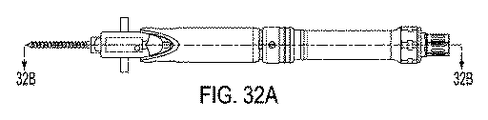
[00164]低減装置600を用いて椎弓根ねじのチューリップ型頭部内のロッドを低減するための方法が示され、本明細書において説明される。図32A〜34Cは、脊椎ロッド112/114を椎弓根ねじ230のチューリップ型頭部234内に低減するためのこの方法のプロセスにおける連続ステップである。そのような方法は、たとえば脊柱側弯、脊柱前湾、および/または脊柱後湾などの脊椎の異常または欠陥を矯正または改善するための方法の一部になり得る。
[00164] A method for reducing a rod in a tulip-shaped head of a pedicle screw using the
[00165]図32A〜34Cは、低減装置600の第2のアセンブリ開口部608内に完全に挿入され、係止された椎弓根ねじ230のチューリップ型頭部を示しており、すなわち、指部510は、チューリップ型頭部234の両側のそれぞれのチューリップ型頭部ポケット236内に完全に挿入され、それにより、指部510の指部フック切下部663が、チューリップ型頭部234のチューリップ型頭部ポケット236のそれぞれのチューリップ型頭部切下部238に係合される。図40A〜40Cに示される実施形態では、チューリップ型頭部234のチューリップ型頭部ポケット236は、チューリップ型頭部の全域にわたって交差方向には延びていない。したがって、この例示的な例では、チューリップ型頭部ポケット236は、チューリップ型頭部切下部238を有する上側壁と、下側壁と、対向する2つの側壁と、を備える。しかし、たとえば、側壁および/または底壁が無いなどの他の構成が利用されてもよいことが理解される。
[00165] FIGS. 32A-34C show the tulip-shaped head of the
[00166]解放リング508が、装置600の第1の端部602に向かって引っ張られたとき、これは、後退スリーブ506をそれぞれ第1の端部602に向かって引っ張り、それにより、指部カムピン514を指部カム内側表面688に沿って第3の領域Cから移行領域Bを通って第1の領域A内へと摺動させ、指部510をチューリップ型頭部から径方向外側に引っ張る。指部カムピン514が領域C内に摺動したとき、指部510は、係止解除位置に移動されて、チューリップ型頭部234のチューリップ型頭部ポケット236の対応するチューリップ型頭部切下部238から指部フック切下部663を係合解除する。この係合解除位置では、チューリップ型頭部234は、低減装置600から取り外され得る。
[00166] When the
[00167]図35Aおよび図35Bを参照すれば、ロッド低減アセンブリ450の一実施形態が示される。前進輪456は、外側低減器シェル454とねじ式係合状態にある。前進輪456の回転は、外側低減器シェル454に対して低減腕部452を強制的に移動させる。
[00167] Referring to FIGS. 35A and 35B, one embodiment of a
[00168]図36Aおよび図36Bを参照すれば、仮係止器具360の実施形態が示される。仮係止器具360は、ロッド低減アセンブリ450の中央シャフト内に挿入され、仮係止器具ねじ山368は、ロッド低減内部ねじ山458に係合される。このねじ式係合は、仮係止アセンブリをロッド低減アセンブリ450内で前進させる。仮係止器具360は、さらに、椎弓根ねじ230のチューリップ型頭部234と係合し、チューリップ型頭部の切下部238を低減腕部452のフランジ付き捕捉部に押し付けて前進させる係止シース362を備える。仮係止器具360が前進されるとき、係止シース362は、チューリップ型頭部234と係合し、前進を停止させる。仮係止器具360の連続的な前進は、椎弓根ねじ230のねじシャフト係止機構と係合する多軸係止歯364を露出させる。多軸係止歯364は、係止シース362によって全体が隠され、係止シース362は、前進ばね366によって前方位置に保持される。
[00168] Referring to FIGS. 36A and 36B, an embodiment of a temporary locking device 360 is shown. Temporary locking instrument 360 is inserted into the central shaft of
[00169]図37A〜図38を参照すれば、椎弓根ねじ挿入器380の実施形態が示される。椎弓根ねじ挿入器380は、たとえば多軸230などの椎弓根ねじを患者に挿入するために使用される。椎弓根ねじ挿入器380は、中央締付シャフト382と、ハンドル384と、摩擦スリーブ386と、ねじ頭部係合スリーブ388と、を備える。中央締付シャフト382は、椎弓根ねじシャフトの駆動頭部に合致するように成形されたドライバ先端部394を有する。たとえば、ドライバ先端部394は、ヘックスローブでもよい。ねじ頭部係合スリーブ388は、ねじ頭部係合ねじ山390を有する。ねじ頭部係合ねじ山は、椎弓根ねじの内部ねじ山と対合して、ねじ頭部係合スリーブ388と椎弓根ねじとを一緒に固定する。ハンドル384および摩擦スリーブ386は、中央締付シャフト382の自由回転を可能にする。
[00169] Referring to FIGS. 37A-38, an embodiment of a
[00170]椎弓根ねじを挿入するために、ねじ頭部係合スリーブ388は、椎弓根ねじの頭部に係合される。中央締付シャフト382のドライバ先端部394は、椎弓根ねじの対合構成に位置合わせされる。摩擦スリーブ386およびハンドル384は、図38に示されるように、摩擦スリーブが、椎弓根ねじの頭部と相互係止するまで中央締付シャフトに沿って移動される。中央締付シャフト382は、回転され、それによって、椎弓根ねじのシャフトをドライバ先端部394との係合によって回転させる。摩擦スリーブ386と椎弓根ねじの頭部との間の相互係止は、椎弓根ねじの挿入プロセス中にねじ頭部係合スリーブが抜け出すことを防止する。摩擦スリーブ386および中央締付シャフト382は、これらの両方が椎弓根ねじの頭部に係合されるので、一体的に回転する。
[00170] To insert a pedicle screw, a screw
[00171]本発明の装置を使用する治療の例示的な方法が、以下の通りに説明される。 [00171] An exemplary method of treatment using the device of the present invention is described as follows.
[00172]最初、埋め込み領域に、外科的に進入される。 [00172] First, a surgical approach is made to the implantation region.
[00173]椎弓根ねじ矯正技術では、胸部の脊椎関節突起切除術が実施される。面関節が取り除かれ、骨鉗子が、部分的な下関節突起骨切り術を実施するために使用される。これは、視覚化を高めるために行われる。3mmから5mmの下関節が除去され、器具装備される下側椎骨上以外の、上関節の関節軟骨が除去される。これは、胸部椎弓根ねじの開始点の手術中の位置特定を可能にし、融合を高める。 [00173] In pedicle screw correction techniques, a thoracic spine arthrotomy is performed. The facet joint is removed and bone forceps are used to perform a partial lower joint process osteotomy. This is done to enhance visualization. The lower joint of 3 to 5 mm is removed, and the articular cartilage of the upper joint other than on the instrumented lower vertebra is removed. This allows for intra-operative localization of the starting point of the thoracic pedicle screw and enhances fusion.
[00174]椎弓根が引き続いて準備される。椎弓根千枚通しまたはバリが、3mm深さの後部皮質の割れ目を作り出すために使用される。椎弓根千枚通しは、ハンドルを軽い圧力で軽くねじることによって前進され得る。椎弓根紅潮が視覚化されて、椎弓根の基部にある海面骨内に入ることを示唆することができるが、この紅潮は、椎弓根間の海面骨が限定されるので小さい椎弓根を準備するときは明白でなくてもよい。椎弓根紅潮が視覚化されないとき、真っすぐなまたは湾曲した椎弓根プローブ、たとえばLenkeプローブを使用して皮質の割れ目内で、椎弓根の入口を示す軟質のじょうご形状の海面骨を探し出す。この手順は、内側皮質の穿孔を回避するために椎弓根プローブの先端部を横方向に向けて実施されなければならない。腹部圧力を大きく作用させ過ぎることを回避するためにハンドルの側部を把持することにより、プローブの先端部は、約2mmから約25mm挿入される。プローブは、プローブの平坦表面が、椎弓根の湾曲部と同じ平面内にあるように配向され、次いで、先端部を内側に向けて取り外され、再挿入される。プローブは、所望の深さまで前進され、約180°回転されてねじのための十分な場所を確保する。触覚プローブは、代替的には床部と呼ばれる穴の基部まで前進され、5つの別個の骨境界部を確認する。5つの骨境界部は、床部および4つの壁である(内側、横方向、上部および下部)。必要であれば、骨ろうまたは他の止血剤が、椎弓根穴内に置かれて出血を抑えることができ、次いで、プローブは、より適切な軌道を有して再配置され得る。 [00174] The pedicle is subsequently prepared. A pedicle prick or burr is used to create a 3 mm deep posterior cortical crevice. The pedicle awl can be advanced by lightly twisting the handle with light pressure. It can be suggested that the pedicle flush is visualized and enters the sea surface bone at the base of the pedicle, but this flush is limited by the sea surface bone between the pedicles, so the small pedicle It may not be obvious when preparing. When the pedicle flush is not visualized, a straight or curved pedicle probe, such as a Lenke probe, is used to locate a soft funnel-shaped sea surface bone that shows the entrance of the pedicle within the cortical crevice. This procedure must be performed with the pedicle probe tip sideways to avoid perforation of the inner cortex. By grasping the side of the handle to avoid overloading the abdominal pressure, the tip of the probe is inserted from about 2 mm to about 25 mm. The probe is oriented so that the flat surface of the probe is in the same plane as the curved portion of the pedicle, then removed with the tip inward and reinserted. The probe is advanced to the desired depth and rotated approximately 180 ° to ensure sufficient space for the screw. The haptic probe is advanced to the base of the hole, alternatively called the floor, to identify five distinct bone boundaries. The five bone boundaries are the floor and four walls (inner, lateral, upper and lower). If necessary, bone wax or other hemostatic agent can be placed in the pedicle hole to reduce bleeding and the probe can then be repositioned with a more appropriate trajectory.
[00175]椎弓根は、適切なねじサイズに合わせて下方穿刺される。椎弓根が下方穿刺された後、可撓性の触覚プローブが使用されて、穿刺された穴にねじ山が存在することを検証することができる。穴の長さを測定するために、触覚プローブが穴の床部まで前進され、止血鉗子が触覚プローブに、これが椎弓根を出る地点に留められる。適切なねじ直径および長さが、引き続いて、術前の測定および手術中の観察の両方に基づいて選択され得る。同じ技術が、器具装備される必要がある残りの椎弓根の各々に対して繰り返される。 [00175] The pedicle is punctured down to the appropriate screw size. After the pedicle is punctured downward, a flexible tactile probe can be used to verify the presence of threads in the punctured hole. To measure the length of the hole, the tactile probe is advanced to the hole floor and the hemostatic forceps are clamped to the tactile probe, where it exits the pedicle. The appropriate screw diameter and length can subsequently be selected based on both preoperative measurements and intraoperative observations. The same technique is repeated for each remaining pedicle that needs to be instrumented.
[00176]単純X線写真または蛍光透視法を用いるX線撮影支援が利用されて、適正なねじ軌道を確実にすることができる。椎弓根マーカが、椎弓根の穴内に置かれ、横方向の視界が得られる。前後の視界もまた得られ得る。 [00176] X-ray imaging support using simple X-ray photography or fluoroscopy can be utilized to ensure proper screw trajectory. A pedicle marker is placed in the hole of the pedicle and a lateral view is obtained. Front and rear views can also be obtained.
[00177]椎弓根ねじ230が、各々の準備された椎弓根内に置かれる。1軸または多軸のねじ230の選択は、手術医の自由裁量であり、いずれの選択肢も予想される。ねじは、適正な追跡を確実にするために椎弓根内をゆっくりと前進されなければならない。椎弓根ねじ230は、脊椎の矯正側の椎弓根ねじの自由通過を可能にする区画ごとにおよび支持側の第3または第4のレベルごとに置かれなければならない。支持側の先端および基端の端部では、少なくとも2つのねじが、挿入されなければならない。より多くのねじを追加した結果、より大きい構造物剛性をもたらす。ねじを置いた際、これらは、骨内のねじ配置を確実にするためにX線撮影支援によって確認されなければならない。椎弓根がカニューレ挿入するには狭すぎると判断された場合、フック210,220、ワイヤまたはテープなどの代替の固定方法が使用されてよい。
[00177] A
[00178]矯正椎弓根ねじの配置がX線撮影支援によって検証された後、脊椎ロッド112,114が準備される。脊椎ロッド112,114は、矢状面および前頭面内で測定され輪郭付けられる。輪郭付ける際、脊椎ロッド112,114は、両方の端部において把持装置にクランプ留めされ、ロッドが回転するのを防止するのを助けることができる。
[00178] After corrective pedicle screw placement has been verified with radiographic assistance,
[00179]適正な輪郭および長さに準備された後、第1のロッドが、先に挿入されたねじ内に置かれる。ロッドを低減し、これを各々の先に配置された椎弓根ねじ内に着座させるために、ロッカ、ロッド低減アセンブリ450または低減装置600が使用され得る。ロッカ方法は、ロッドとインプラントサドルとの間の高さの相違が僅かしか存在しないときにロッドをインプラントに低減するための効果的な方法である。ロッカ方法を用いてロッドを低減するために、インプラントの側部が、ロッカカムをロッドの上方にして握られる。ロッカは、ロッドの上方で後ろ方向にてこ作用されてロッドをインプラントのサドル内に着座させる。止めねじが、引き続いて置かれ、仮締め付けされてロッドを所定場所に保持するように締め付けられる。
[00179] After being prepared to the proper profile and length, the first rod is placed in the previously inserted screw. A rocker,
[00180]ロッド低減アセンブリ450を用いたロッドの低減のために、椎弓根ねじおよびロッドが所定場所にある状態で、ロッド低減アセンブリがねじの頭部の上方にあてられる。仮係止器具360が、ロッド低減アセンブリ450管に下向きに挿入され、下向きにねじ込まれて仮係止構成と係合する。あるいは、仮係止器具360が、ロッド低減アセンブリ450の管に下向きに挿入されて部分的に下向きにねじ込まれてからロッド低減アセンブリをねじ頭部に固着してもよい。ロッドは、次いで、ロッド低減アセンブリ450の前進輪456を回すことによって低減される。ロッドを低減するのにより大きいトルクが必要である場合、軸線方向に取り付けられた低減アダプタ1100またはトルク限定Tハンドルが、ロッド低減アセンブリ450の前進輪456と接面することができる。仮係止器具は、引き続いて、ロッド低減アセンブリが仮係止係合を引き継いでいるために取り外される。止めねじドライバ850は、止めねじを導入するために使用される。止めねじは、これがねじ山上で底付きするまでロッド低減アセンブリ450の中央空洞を下向きに通される。止めねじの交差ねじ込みを回避するために、止めねじは、クリック音が感じられるまで反時計周りに回され、その後時計周りに回されて締め付ける。
[00180] For rod reduction using the
[00181]ロッド低減装置600を用いたロッドの低減のために、椎弓根ねじおよびロッドが所定場所にある状態で、ロッド手低減アセンブリがねじのチューリップ型頭部234の上方にあてられる。ロッド低減アセンブリ600の指部510は、椎弓根ねじのチューリップ型頭部234のチューリップ型頭部ポケット236と係合する。ロッドは、次いで、ロッド低減装置600の前進ノブ502を回すことによって低減される。ロッドを低減するのにより大きいトルクが必要である場合、軸線方向に取り付けられた低減アダプタ1100またはトルク限定Tハンドルが、ロッド低減アセンブリ600の前進ノブ502と接面することができる。止めねじドライバ850は、止めねじを導入するために使用される。止めねじは、これがねじ山上で底付きするまでロッド低減アセンブリ600の第1のアセンブリ開口部606内を通される。止めねじの交差ねじ込みを回避するために、止めねじは、クリック音が感じられるまで反時計周りに回され、その後時計周りに回されて締め付ける。
[00181] For rod reduction using the
[00182]止めねじを緩くするか、または、一方の端部のみで係止されたまま、脊椎ロッド112,114は、管状曲げ型を用いてゆっくりと真っすぐにされる。脊椎ロッド112,114を完全に真っすぐにするにはいくつかの型を必要とし得る。
[00182] The
[00183]輪郭付けされたロッドおよびすべての止めねじが置かれた後、輪郭付けされたロッドは、その最終位置に回転される。回転は、脊髄に対する急速な神経学的変化および/または外傷を防止するためにゆっくりと行われなければならない。2つのロッドホルダを用いて、輪郭付けされたロッドが所望の位置に回転される。頂点の止めねじが締め付けられ、圧縮または伸延が実施され得る。すべての矯正操作中、ねじおよび骨の接面部は監視されなければならない。 [00183] After the contoured rod and all set screws are placed, the contoured rod is rotated to its final position. The rotation must be done slowly to prevent rapid neurological changes and / or trauma to the spinal cord. Using two rod holders, the contoured rod is rotated to the desired position. The apex setscrew can be tightened and compression or distraction can be performed. During all orthodontic operations, the screw and bone interface must be monitored.
[00184]第2のロッドおよびそのそれぞれの止めねじは、先に概説された技術によって配置される。第2のロッドおよび止めねじの配置に続き、凸状圧縮力が、平行圧縮機を用いて区画上に加えられて最も下側の器具装備された椎骨を水平化し、その変形の凸状部を軽く圧縮する。圧縮は、最終締め付けの直前に解放されることが好ましい。この技術は、インプラント頭部およびロッドが、互いに標準化され、最終締め付けステップ中に、ロッドをインプラント頭部内に完全に着座させることを可能にすることを確実にするのに役立つ。 [00184] The second rod and its respective set screw are placed by the techniques outlined above. Following the placement of the second rod and set screw, a convex compressive force is applied on the compartment using a parallel compressor to level the lowest instrumented vertebra, and the convex portion of the deformation is Compress lightly. The compression is preferably released just before final tightening. This technique helps to ensure that the implant head and rod are standardized with each other and allow the rod to be fully seated within the implant head during the final tightening step.
[00185]すべてのロッドおよびねじが配置され、止めねじを用いて事前に固定された状態で、止めねじは、その最終トルクに締め付けられる。カウンタトルクレンチおよび止めねじドライバ850が、開放ねじ、サドル、および、止めねじ上に置かれる。トルク限定Tハンドルが、止めねじドライバ850上に配置され、カウンタトルクレンチを固く保持しながら時計周り方向に回される。トルク限定Tハンドルは、好ましくは、70ポンド(31.75kg)に設定される。Tハンドルは、可聴クリック音が聞かれて適正なトルクが満たされていることを示すまで時計周りに回される。
[00185] With all rods and screws in place and pre-fixed with a set screw, the set screw is tightened to its final torque. A counter torque wrench and set
[00186]止めねじの最終締め付け後、交差連結器が配置される。交差連結器の連結は、骨組構造物が回転力に耐えるので、構造物に対して回転的安定性をもたらす。交差連結器は、構造物先端部近くに配置されなければならないが、構造物に沿った他の位置における配置もまた想定される。 [00186] After final tightening of the set screw, the cross-connector is placed. The connection of the cross-connector provides rotational stability to the structure as the frame structure withstands rotational forces. The cross-connector must be placed near the structure tip, but placement at other locations along the structure is also envisioned.
[00187]2軸交差連結器330は、ロッドを、各々の連結機構334,336の端部にある交差連結器ロッドフック322の各々内に捕捉することによって脊椎ロッド112,114に固着される。2軸交差連結器330を脊椎ロッド112,114に取り付ける前に、中央ナット338または中央係止ねじ339が事前に締め付けられる。第1のロッドは、連結機構334,336の1つの端部にある交差連結器ロッドフック322内に捕捉され、円錐ねじ302が、装置をロッドに固定するために事前に締め付けられる。中央ナット338または中央係止ねじ339は、連結機構334,336が角度付けられ、長くまたは短くされることを可能にするために緩められる。第2のロッドは、他方の連結機構334,336の端部にある交差連結器ロッドフック322内に捕捉され、円錐ねじ302が事前に締め付けられる。中央ナット338または中央係止ねじ339は、2軸交差連結器330の連結機構334,336を固定するために再締め付けされる。円錐ねじ302の最終締め付けのために、カウンタトルク管およびねじドライバが、2軸交差連結器330、脊椎ロッド112,114および円錐ねじ上に配置される。トルク限定Tハンドルが、ドライバシャフト上に配置され、カウンタトルクレンチを固く保持しながら時計周りに回される。トルク限定Tハンドルは、好ましくは、50ポンド(22.68kg)に設定される。Tハンドルは、可聴クリック音が聞かれて適正なトルクが満たされていることを示すまで時計周りに回される。
[00187] The
[00188]固定された交差連結器300は、固定された交差連結器を、ロッドが各々の交差連結器ロッドフック322内に着座するようにロッドの上方に配置することによって、脊椎ロッド112,114に固着される。円錐ねじ302が、事前に締め付けられ、次いで、2軸交差連結器330と同様にカウンタトルク管、ドライバシャフト、およびトルク限定Tハンドルを用いて最終的に締め付けられる。一部の用途では、固定された交差連結器300の固定された交差連結器延長ロッド304は、生体構造および脊椎ロッド112,114の構成に嵌合するように曲げられる必要があり得る。
[00188] The fixed cross-connector 300 places the fixed cross-connector above the rod so that the rod sits within each
[00189]フック210,220を基本にした矯正技術に関しては、手術部位が、関節面被膜を分割することによって準備される。下関節突起の一部分もまた、フック210,220の挿入を容易にするために除去され得る。椎弓根は、椎弓根エレベータを用いて明確に特定されなければならない。椎弓根フックは、フック刃212を頭にして椎弓根間位置にしてT1からT10に挿入され得る。フック210,220のフック刃212は、椎弓根の周りに巻き付け、下関節突起を分割してはならない。適所において椎弓根フックを補助するために、フック押出装置が利用され得る。
[00189] For orthodontic techniques based on
[00190]交差方向突起におけるフックの配置のために、幅広の刃フックが、通常、尾側フックとして椎弓根−交差爪構造物内で使用される。椎弓板フックの試みは、靭帯取り付け部を横突起の下面と、助骨横関節の内側の助骨の椎後弓と、に分離するために使用され得る。フックは次いで、フックホルダを用いて挿入される。 [00190] A wide blade hook is typically used in the pedicle-crossing claw structure as a caudal hook for the placement of the hook in the crosswise projection. A lamina hook approach can be used to separate the ligament attachment into the lower surface of the transverse process and the posterior vertebral arch of the bone inside the prosthetic transverse joint. The hook is then inserted using a hook holder.
[00191]胸部フックの配置のために、器具装備される椎骨のすぐ上方の棘突起の部分的または完全な分割が実施され得る。黄色靭帯の分割および/または部分的除去ならびに少しの椎弓切開術が、上椎弓板上に実施される。椎弓板から除去された骨の量は、選択されたフック刃212のサイズ、および、のど部角度に応じて変動し得る。椎弓板下方の上側縁または椎弓板上方の下側縁が、フック210,220配置を容易にするために切除され得る。椎弓板フックの試みは、ここでも使用されて椎弓板と椎弓根構造との間の間隔を確認することができる。フック210,220を上椎弓板上に置くときに、フックを挿入するためにフックが使用されなければならない。
[00191] For placement of the chest hook, a partial or complete segmentation of the spinous process just above the instrumented vertebra may be performed. A segmentation and / or partial removal of the ligamentum flavum and a small laminectomy are performed on the superior lamina. The amount of bone removed from the lamina can vary depending on the size of the selected
[00192]すべての適切なフックが矯正されるべき変形部の側に置かれた状態で、ロッドテンプレートが使用されて長さおよび曲線を測定する。矯正側の脊椎ロッド112,114は、矯正のための適切な長さを残すために実際の長さより2〜3cm長く切断されなければならない。脊椎ロッド112,114は、次いで、フレンチ曲げ型または管状曲げ型を用いて矯正方向に曲げられる。
[00192] With all appropriate hooks placed on the side of the deformation to be corrected, a rod template is used to measure length and curve. The corrective
[00193]脊椎ロッド112,114の挿入前に安定的でないすべてのフック210,220は、ロッドの配置までに取り外されなければならない。
[00193] All hooks 210, 220 that are not stable prior to insertion of
[00194]脊椎ロッド112,114および止めねじ120は、椎弓根ねじに関して概説された同じ技術によって置かれ事前に締め付けられる。回転、生体内曲げ、圧縮および伸延の操作が行われて完了され得る。ロッド回転中に間隔フックは戻る傾向があるので、これらを監視することが重要である。
[00194] The
[00195]変形部矯正を完了し、矯正ロッドを着座させると、構造物の反対側が準備される。フレンチ曲げ器を用いて、構造物の反対側のロッドが、脊椎の湾曲および矯正ロッドからの位置合わせの残りの位置にしたがって輪郭付けされる。輪郭付けされたロッドは、ロッドホルダまたは手動でフック210,220内に配置され、止めねじ120で事前に固定される。脊椎ロッド112,114がインプラントに固定された状態で、伸延および/または圧縮が、フック210,220をその最終位置に置くために実施される。止めねじ120は、引き続いて、椎弓根ねじおよび交差連結器300,330に関して先に論じられた技術にしたがって最終的に締め付けられる。
[00195] Once the deformity correction is completed and the correction rod is seated, the opposite side of the structure is prepared. Using a French bender, the rod on the opposite side of the structure is contoured according to the remaining position of the spine curvature and alignment from the correction rod. The contoured rod is placed in the
[00196]交差連結器300,330もまた、好ましくは回転安定性を追加するために構造物に追加される。
[00196]
[00197]これは、例示的な手術技術にすぎず、技術内で概説されたステップを実施するための他の知られている、許容される方法または技術が、適宜代用され得る。 [00197] This is only an exemplary surgical technique and other known and accepted methods or techniques for performing the steps outlined within the technique may be substituted as appropriate.
[00198]先の本文は、数多くの異なる実施形態の幅広い説明を記載している。説明は、例示的のみであると解釈されるものであり、すべての可能な実施形態を説明することは不可能ではないが実用的ではないため、すべての可能な実施形態を説明せず、さらに、本明細書において説明された任意の特徴、特性、構成要素、ステップまたは方法論が、削除され、また全体的または部分的に、本明細書において説明された任意の他の特徴、特性、構成要素、ステップまたは方法論と組み合わせられ、または、これらに代用されることが可能であることが理解されよう。現在の技術、または本特許の出願日以降に開発される技術を用いて数多くの代替の実施形態が実施されてもよく、これは、特許請求の範囲内に依然として含まれるものである。 [00198] The preceding text provides a broad description of many different embodiments. The description is to be construed as illustrative only and not all possible embodiments are described, as it is not impossible but impractical to describe all possible embodiments. Any feature, characteristic, component, step or methodology described herein has been deleted and, in whole or in part, any other feature, characteristic, component described herein It will be understood that these can be combined with, or substituted for, steps or methodologies. Numerous alternative embodiments may be implemented using current technology, or technology developed after the filing date of this patent, and still fall within the scope of the claims.
[00199]また、用語が、「本明細書では、用語は「 」は...を意味すると本明細書によって定義される」という文章、または類似の文章を用いて本明細書において明示的に規定されない限り、その平常のまたは通常の意味を超えるその用語の意味を、明示的または暗示的に限定することは意図せず、そのような用語は、(特許請求の範囲の言語以外の)本特許の任意の項においてなされる任意の記述に基づいて範囲が限定されるものと解釈されてはならないことも理解されたい。用語は、そのように記載されない限り、必須であることは意図されない。本特許の末の特許請求の範囲に記載される任意の用語が、1つの意味と一致させた方法で本明細書において示される場合では、これは、読み手を混乱させないようにするための明確性のために行われ、そのような特許請求項の用語が、暗示的または別の形でその単一の意味に限定されることは意図されない。最終的には、特許請求項の範囲の要素が、任意の構造を列挙せずに用語「手段」および機能を列挙することによって規定されない限り、任意の特許請求項の範囲の要素の範囲は、US特許法112条6段落目または類似の原則の適用に基づいて解釈されることは意図されない。
[00199] Also, the term “in this specification, the term“ ”is. . . As defined by this specification to mean, or similar terms, the meaning of that term is expressly It is not intended to be implicitly limited and such terms are to be construed as being limited in scope based on any statements made in any section of this patent (other than the language of the claims). It should also be understood that it must not be done. Terms are not intended to be essential unless stated as such. Where any term set forth in the claims at the end of this patent is presented herein in a manner consistent with one meaning, this is clarity to avoid confusion for the reader. It is not intended that the terms of such claims be limited to their single meanings, either implicitly or otherwise. Ultimately, unless an element in a claim is defined by enumerating the terms “means” and function without enumerating any structure, the scope of the element in any claim is It is not intended to be construed based on the application of
[00200]また、「少なくとも1つの」の構成要素、要素などの本明細書における列挙は、前置詞「1つ(a)」または「1つ(an)」の代替的使用が、単一の構成要素、要素等に限定されなければならないという推定を生み出すために使用されてはならないことに留意されたい。 [00200] In addition, the recitation herein of "at least one" component, element, etc., is an alternative use of the preposition "one (a)" or "one (an)" is a single component. Note that it must not be used to generate an assumption that it should be limited to elements, elements, etc.
[00201]特定の特性または特定の方法における機能を組み込むように「構成される」本開示の構成要素の本明細書における列挙は、意図される使用の列挙とは対照的な構造的列挙であることに留意されたい。より詳細には、構成要素が「構成される」形に対する本明細書における参照は、構成要素の既存の物理的状態を示し、したがって、構成要素の構造的特性の明確な列挙としてとられるものである。 [00201] An enumeration herein of a component of the present disclosure that is "configured" to incorporate a particular property or function in a particular way is a structural enumeration as opposed to an enumeration of intended uses. Please note that. More particularly, references herein to the form in which a component is “configured” indicate the existing physical state of the component and are therefore taken as a clear listing of the structural characteristics of the component. is there.
[00202]本明細書で使用される場合の「好ましくは」、「一般的には」、および「通常」のような用語は、特許請求される本発明の範囲を限定し、特定の特徴が、特許請求される本発明の構造または機能に対して重大であり、必須であり、または重要であることを暗示するように使用されないことに留意されたい。むしろ、これらの用語は、本開示の実施形態の特定の態様を特定し、または本開示の特定の実施形態において利用されても利用されなくてもよい代替のまたは追加の特徴を強調することが意図されるにすぎない。 [00202] Terms such as "preferably", "generally" and "usually" as used herein limit the scope of the claimed invention and have certain features It should be noted that it is not used to imply that it is critical, essential or important to the structure or function of the claimed invention. Rather, these terms may identify particular aspects of embodiments of the present disclosure or highlight alternative or additional features that may or may not be utilized in certain embodiments of the present disclosure. It is only intended.
[00203]本発明を説明し規定する目的で、用語「実質的に」および「約」は、任意の定量的比較、値、測定、または他の表現に起因し得る不確か性の固有の程度を表すために本明細書において利用されることに留意する。また、用語「実質的に」および「約」は、定量的表現が、論争中の主題の基本的機能における変化をもたらさずに記載された基準から変動することができる程度を表すために利用される。 [00203] For purposes of describing and defining the present invention, the terms "substantially" and "about" refer to the inherent degree of uncertainty that may result from any quantitative comparison, value, measurement, or other representation. Note that it is used herein to represent. The terms “substantially” and “about” are also used to describe the extent to which a quantitative expression can vary from the stated criteria without causing a change in the basic function of the subject matter in question. The
[00204]本開示の主題を詳細にかつその特有の実施形態を参照することによって説明してきたが、本明細書において開示されるさまざまな詳細は、これらの詳細が、特定の要素が、本説明に添付される図の各々において示される場合であっても、本明細書において開示されるさまざまな実施形態の必須の構成要素である要素に関するものであると示唆するようとらえられてはならないことに留意されたい。むしろ、本明細書に付属の特許請求の範囲が、本開示の広がりおよび本明細書において説明されるさまざまな本発明の対応する範囲の唯一の代表物としてとらえられなければならない。さらに、添付の特許請求の範囲において定義された本発明の範囲から逸脱することなく、改変形態および変形形態が可能であることが明確になろう。より詳細には、本開示の一部の態様は、本明細書において好ましいまたは特に有利であると特定されるが、本開示がこれらの態様に必ずしも限定されないことが考慮される。 [00204] While the subject matter of this disclosure has been described in detail and with reference to specific embodiments thereof, the various details disclosed herein are not limited to those details, and certain elements Even if shown in each of the figures attached to, it should not be taken to imply that it relates to an element that is an essential component of the various embodiments disclosed herein. Please keep in mind. Rather, the claims appended hereto must be taken as the sole representative of the breadth of the present disclosure and the corresponding scope of the various inventions described herein. Furthermore, it will be apparent that modifications and variations are possible without departing from the scope of the invention as defined in the appended claims. More specifically, although certain aspects of the present disclosure are identified as preferred or particularly advantageous herein, it is contemplated that the present disclosure is not necessarily limited to these aspects.
[00205]本明細書において開示される寸法および値は、列挙された数値そのものに厳密に限定されると理解されるものではない。その代わり、別途明記されない限り、各々のそのような寸法は、列挙された値およびその値周辺の機能的に等価な範囲の両方を意味することが意図される。たとえば、「40mm」として開示される寸法は、「約40mm」を意味することが意図される。 [00205] The dimensions and values disclosed herein are not to be understood as being strictly limited to the recited numerical values themselves. Instead, unless otherwise specified, each such dimension is intended to mean both the recited value and a functionally equivalent range surrounding that value. For example, a dimension disclosed as “40 mm” is intended to mean “about 40 mm”.
[00206]相互参照特許または関連特許または出願を含む本明細書に引用されるすべての文献は、明示的に排除されず、または、別の形で限定されない限り、全体的に参照によって本明細書に組み込まれる。任意の特許文献の引用は、これが、本明細書において開示されまたは特許請求される任意の発明に関する従来技術であり、またはこれが、単独でまたは任意の他の参照文献または複数の参照文献と任意に組み合わせて、任意のそのような発明を教示、提案、または開示するという承認ではない。さらに、この文献内の用語の任意の意味または定義が、参照によって組み込まれた文献内の同じ用語の任意の意味または定義に矛盾する場合、本文献のその用語に割り当てられた意味または定義を優先するものとする。 [00206] All documents cited herein, including cross-reference patents or related patents or applications, are hereby incorporated by reference in their entirety unless expressly excluded or otherwise limited. Incorporated into. The citation of any patent document is either prior art with respect to any invention disclosed or claimed herein, or is optional, either alone or with any other reference or references. In combination, there is no admission that any such invention is taught, proposed or disclosed. In addition, if any meaning or definition of a term in this document contradicts any meaning or definition of the same term in a document incorporated by reference, the meaning or definition assigned to that term in this document takes precedence. It shall be.
[00207]本発明の特定の実施形態が図示され説明されてきたが、さまざまな他の変更および改変が加えられ得ることが当業者に明確である。したがって、すべてのそのような変更および改変を付属の特許請求の範囲内で網羅することが意図される。 [00207] While particular embodiments of the present invention have been illustrated and described, it will be apparent to those skilled in the art that various other changes and modifications can be made. Accordingly, it is intended to embrace all such changes and modifications within the scope of the appended claims.
Claims (8)
脊椎ロッド受入チャネルと、
ロッド保持止めねじと
を備え、
前記脊椎ロッド受入チャネルは、第1の円形穴と第2の円形穴と第3の円形穴との3つの穴の複合体を備え、
前記第1の円形穴、前記第2の円形穴および前記第3の円形穴は、平行であり、
前記第1の円形穴、前記第2の円形穴および前記第3の円形穴は、単一線に沿って配置されたずれた中心を有し、
前記第1の円形穴は、前記ロッド受入チャネルの上側の弧を形成し、
前記第2の円形穴は、前記ロッド受入チャネルの中間の弧を形成し、
前記第3の円形穴は、前記ロッド受入チャネルの下側の弧を形成し、
前記第1の円形穴の半径は、前記第2の円形穴の半径よりも大きく、
前記第2の円形穴の半径は、前記第3の円形穴の半径よりも大きく、
前記中間の弧および前記下側の弧は、まっすぐな連結斜面によって連結され、
前記ロッド保持止めねじは、前記脊椎ロッド受入チャネル内に配置された脊椎ロッドを前記医療装置内に固定する
医療装置。 A medical device,
A spinal rod receiving channel;
Rod holding set screw and
The spinal rod receiving channel comprises a complex of three holes of the first circular hole and the second circular hole and the third circular hole,
The first circular hole, the second circular hole and the third circular hole are parallel;
The first circular hole, the second circular hole, and the third circular hole have offset centers disposed along a single line;
The first circular hole forms an upper arc of the rod receiving channel;
The second circular hole forms an intermediate arc of the rod receiving channel;
The third circular hole forms a lower arc of the rod receiving channel;
The radius of the first circular hole is greater than the radius of the second circular hole;
The radius of the second circular hole is larger than the radius of the third circular hole,
The middle arc and the lower arc are connected by a straight connecting ramp;
The rod retention set screw secures a spinal rod disposed within the spinal rod receiving channel within the medical device.
前記医療装置は、平行配置で配置された複数のロッド受入チャネルを備える
医療装置。 The medical device according to claim 1,
The medical device comprises a plurality of rod receiving channels arranged in a parallel arrangement.
前記医療装置は、各々のロッド受入チャネルと組み合わせる単一のロッド保持止めねじを備える
医療装置。 The medical device according to claim 1,
The medical device comprises a single rod retention set screw that is associated with each rod receiving channel.
前記医療装置は、各々のロッド受入チャネルと組み合わせる2つのロッド保持止めねじを備える
医療装置。 The medical device according to claim 1,
The medical device comprises two rod retaining set screws combined with each rod receiving channel.
前記第1の円形穴は、約2.76mm以上かつ約3.02mm以下の半径を有し、
前記第2の円形穴は、約2.595mm以上かつ約2.855mm以下の半径を有し、
前記第3の円形穴は、約1.87mm以上かつ約2.13mm以下の半径を有する
医療装置。 The medical device according to claim 1,
The first circular hole has a radius of about 2.76 mm or more and about 3.02 mm or less;
The second circular hole has a radius of about 2.595 mm or more and about 2.855 mm or less;
The third circular hole has a radius of about 1.87 mm or more and about 2.13 mm or less.
前記まっすぐな連結斜面は、約0.638mm以上かつ約0.898mm以下の長さを有する
医療装置。 The medical device according to claim 5,
The straight connecting slope has a length of about 0.638 mm or more and about 0.898 mm or less.
前記医療装置は、椎骨の椎弓板との係合のためのフックを備える
医療装置。 The medical device according to claim 1,
The medical device comprises a hook for engagement with a vertebral lamina.
前記医療装置は、椎弓根ねじとの係合のための、約4.75mmまたは約5.5mmの直径を有する横方向連結器ロッドを備える
医療装置。 The medical device according to claim 1,
The medical device comprises a lateral connector rod having a diameter of about 4.75 mm or about 5.5 mm for engagement with a pedicle screw.
Applications Claiming Priority (5)
| Application Number | Priority Date | Filing Date | Title |
|---|---|---|---|
| US201261646030P | 2012-05-11 | 2012-05-11 | |
| US61/646,030 | 2012-05-11 | ||
| US201361798414P | 2013-03-15 | 2013-03-15 | |
| US61/798,414 | 2013-03-15 | ||
| PCT/US2013/040778 WO2013170262A2 (en) | 2012-05-11 | 2013-05-13 | Surgical connectors and instrumentation |
Related Child Applications (1)
| Application Number | Title | Priority Date | Filing Date |
|---|---|---|---|
| JP2017150918A Division JP6417456B2 (en) | 2012-05-11 | 2017-08-03 | Surgical couplers and instruments |
Publications (2)
| Publication Number | Publication Date |
|---|---|
| JP2015523111A JP2015523111A (en) | 2015-08-13 |
| JP6189939B2 true JP6189939B2 (en) | 2017-08-30 |
Family
ID=49551479
Family Applications (7)
| Application Number | Title | Priority Date | Filing Date |
|---|---|---|---|
| JP2015511801A Active JP6189939B2 (en) | 2012-05-11 | 2013-05-13 | Surgical couplers and instruments |
| JP2017150918A Active JP6417456B2 (en) | 2012-05-11 | 2017-08-03 | Surgical couplers and instruments |
| JP2017209747A Active JP6326542B2 (en) | 2012-05-11 | 2017-10-30 | Surgical couplers and instruments |
| JP2018078105A Active JP6568619B2 (en) | 2012-05-11 | 2018-04-16 | Surgical couplers and instruments |
| JP2019143566A Active JP6822698B2 (en) | 2012-05-11 | 2019-08-05 | Surgical couplers and instruments |
| JP2020216006A Active JP7099750B2 (en) | 2012-05-11 | 2020-12-25 | Surgical couplers and instruments |
| JP2022100761A Pending JP2022126797A (en) | 2012-05-11 | 2022-06-23 | Surgical connectors and instrumentation |
Family Applications After (6)
| Application Number | Title | Priority Date | Filing Date |
|---|---|---|---|
| JP2017150918A Active JP6417456B2 (en) | 2012-05-11 | 2017-08-03 | Surgical couplers and instruments |
| JP2017209747A Active JP6326542B2 (en) | 2012-05-11 | 2017-10-30 | Surgical couplers and instruments |
| JP2018078105A Active JP6568619B2 (en) | 2012-05-11 | 2018-04-16 | Surgical couplers and instruments |
| JP2019143566A Active JP6822698B2 (en) | 2012-05-11 | 2019-08-05 | Surgical couplers and instruments |
| JP2020216006A Active JP7099750B2 (en) | 2012-05-11 | 2020-12-25 | Surgical couplers and instruments |
| JP2022100761A Pending JP2022126797A (en) | 2012-05-11 | 2022-06-23 | Surgical connectors and instrumentation |
Country Status (5)
| Country | Link |
|---|---|
| US (2) | US9844398B2 (en) |
| EP (2) | EP2846718B1 (en) |
| JP (7) | JP6189939B2 (en) |
| AU (2) | AU2013259052B2 (en) |
| WO (1) | WO2013170262A2 (en) |
Families Citing this family (29)
| Publication number | Priority date | Publication date | Assignee | Title |
|---|---|---|---|---|
| US9579126B2 (en) | 2008-02-02 | 2017-02-28 | Globus Medical, Inc. | Spinal rod link reducer |
| JP6189939B2 (en) * | 2012-05-11 | 2017-08-30 | オーソペディアトリクス・コーポレーション | Surgical couplers and instruments |
| AU2014259592B2 (en) * | 2013-11-15 | 2019-05-16 | K2M, Inc. | System for corrective spinal surgery and method of use |
| US9486252B2 (en) * | 2014-01-09 | 2016-11-08 | Warsaw Orthopedic, Inc. | Spinal correction system and method |
| US10307185B2 (en) | 2016-03-29 | 2019-06-04 | Globus Medical, Inc. | Revision connectors, systems, and methods thereof |
| US10624679B2 (en) | 2016-03-29 | 2020-04-21 | Globus Medical, Inc. | Revision connectors, systems and methods thereof |
| US10383663B2 (en) | 2016-03-29 | 2019-08-20 | Globus Medical, Inc. | Revision connectors, systems and methods thereof |
| US9980755B2 (en) | 2016-03-29 | 2018-05-29 | Globus Medical, Inc. | Revision connectors, systems, and methods thereof |
| US10321939B2 (en) | 2016-05-18 | 2019-06-18 | Medos International Sarl | Implant connectors and related methods |
| US10517647B2 (en) | 2016-05-18 | 2019-12-31 | Medos International Sarl | Implant connectors and related methods |
| KR101910597B1 (en) * | 2016-12-02 | 2018-10-22 | 안경기 | Rod connector |
| US10398476B2 (en) | 2016-12-13 | 2019-09-03 | Medos International Sàrl | Implant adapters and related methods |
| US10492835B2 (en) | 2016-12-19 | 2019-12-03 | Medos International Sàrl | Offset rods, offset rod connectors, and related methods |
| US10779866B2 (en) | 2016-12-29 | 2020-09-22 | K2M, Inc. | Rod reducer assembly |
| US10238432B2 (en) * | 2017-02-10 | 2019-03-26 | Medos International Sàrl | Tandem rod connectors and related methods |
| US10561454B2 (en) | 2017-03-28 | 2020-02-18 | Medos International Sarl | Articulating implant connectors and related methods |
| US10966761B2 (en) | 2017-03-28 | 2021-04-06 | Medos International Sarl | Articulating implant connectors and related methods |
| US11246634B2 (en) | 2017-05-02 | 2022-02-15 | Orthopediatrics Corp. | End cap for intramedullary nail |
| US11076890B2 (en) | 2017-12-01 | 2021-08-03 | Medos International Sàrl | Rod-to-rod connectors having robust rod closure mechanisms and related methods |
| US11006980B2 (en) | 2018-02-28 | 2021-05-18 | Kabushiki Kaisha Hikari | Surgical medical instrument for spinal fixation |
| DE102019113097B3 (en) * | 2019-05-17 | 2020-11-12 | Aesculap Ag | Medical cross connector with floating storage and medical product set with the medical cross connector |
| US20230129404A1 (en) * | 2020-01-28 | 2023-04-27 | Orthopediatrics Corp. | Spinal rod-to-rod connectors |
| US11134994B2 (en) * | 2020-01-30 | 2021-10-05 | Warsaw Orthopedic, Inc. | Spinal-correction system having threaded extender tabs and reduction tab extenders |
| DE102020108276A1 (en) * | 2020-03-25 | 2021-09-30 | Aesculap Ag | Surgical connector and surgical connector system |
| WO2022056025A1 (en) * | 2020-09-09 | 2022-03-17 | Orthopediatrics Corporation | Rod reduction device |
| US11284924B1 (en) | 2020-12-16 | 2022-03-29 | Warsaw Orthopedic, Inc | Adjustable spinal implant, system and method |
| US11350969B1 (en) | 2021-02-02 | 2022-06-07 | Warsaw Orthopedic, Inc. | Rotatable spinal implant, system, and method |
| US20220354546A1 (en) * | 2021-05-07 | 2022-11-10 | Globus Medical, Inc. | Connectors, systems, and methods therof |
| US20220395296A1 (en) * | 2021-06-11 | 2022-12-15 | Phoenix Children's Hospital, Inc. | Spinal hook |
Family Cites Families (173)
| Publication number | Priority date | Publication date | Assignee | Title |
|---|---|---|---|---|
| SE9002569D0 (en) * | 1990-08-03 | 1990-08-03 | Sven Olerud | SPINAL KNUT |
| EP0553424A1 (en) * | 1992-01-30 | 1993-08-04 | Acromed Corporation | Spinal column retaining apparatus |
| US5217461A (en) | 1992-02-20 | 1993-06-08 | Acromed Corporation | Apparatus for maintaining vertebrae in a desired spatial relationship |
| FR2697742B1 (en) * | 1992-11-06 | 1994-12-16 | Biomat | Osteosynthesis device for spinal consolidation. |
| US5702395A (en) | 1992-11-10 | 1997-12-30 | Sofamor S.N.C. | Spine osteosynthesis instrumentation for an anterior approach |
| US5498262A (en) | 1992-12-31 | 1996-03-12 | Bryan; Donald W. | Spinal fixation apparatus and method |
| US5330473A (en) | 1993-03-04 | 1994-07-19 | Advanced Spine Fixation Systems, Inc. | Branch connector for spinal fixation systems |
| US5601554A (en) | 1993-03-04 | 1997-02-11 | Advanced Spine Fixation Systems, Inc. | Branch connector for spinal fixation systems |
| US6077262A (en) | 1993-06-04 | 2000-06-20 | Synthes (U.S.A.) | Posterior spinal implant |
| US5601552A (en) * | 1994-03-18 | 1997-02-11 | Sofamor, S.N.C. | Fixing device for a rigid transverse connection device between rods of a spinal osteosynthesis system |
| ATE196983T1 (en) * | 1994-06-30 | 2000-11-15 | Sulzer Orthopaedie Ag | DEVICE FOR CONNECTING VERTEBRATE BONES |
| US5609593A (en) | 1995-07-13 | 1997-03-11 | Fastenetix, Llc | Advanced polyaxial locking hook and coupling element device for use with top loading rod fixation devices |
| US5609594A (en) | 1995-07-13 | 1997-03-11 | Fastenetix Llc | Extending hook and polyaxial coupling element device for use with side loading road fixation devices |
| US5578033A (en) | 1995-07-13 | 1996-11-26 | Fastenetix, L.L.C. | Advanced polyaxial locking hook and coupling element device for use with side loading rod fixation devices |
| US5733285A (en) | 1995-07-13 | 1998-03-31 | Fastenetix, Llc | Polyaxial locking mechanism |
| US5575792A (en) | 1995-07-14 | 1996-11-19 | Fastenetix, L.L.C. | Extending hook and polyaxial coupling element device for use with top loading rod fixation devices |
| US5697929A (en) | 1995-10-18 | 1997-12-16 | Cross Medical Products, Inc. | Self-limiting set screw for use with spinal implant systems |
| US5688274A (en) | 1995-10-23 | 1997-11-18 | Fastenetix Llc. | Spinal implant device having a single central rod and claw hooks |
| US5688273A (en) | 1995-10-23 | 1997-11-18 | Fastenetix, Llc. | Spinal implant apparatus having a single central rod and plow hooks |
| US5810818A (en) | 1995-10-23 | 1998-09-22 | Fastenetix, Llc | Spinal hook implant having a low blade and S swivel hook |
| US5964760A (en) | 1996-10-18 | 1999-10-12 | Spinal Innovations | Spinal implant fixation assembly |
| US5863293A (en) | 1996-10-18 | 1999-01-26 | Spinal Innovations | Spinal implant fixation assembly |
| US5720751A (en) | 1996-11-27 | 1998-02-24 | Jackson; Roger P. | Tools for use in seating spinal rods in open ended implants |
| US20050245937A1 (en) | 2004-04-28 | 2005-11-03 | St. Francis Medical Technologies, Inc. | System and method for insertion of an interspinous process implant that is rotatable in order to retain the implant relative to the spinous processes |
| US7201751B2 (en) * | 1997-01-02 | 2007-04-10 | St. Francis Medical Technologies, Inc. | Supplemental spine fixation device |
| US5752957A (en) | 1997-02-12 | 1998-05-19 | Third Millennium Engineering, Llc | Polyaxial mechanism for use with orthopaedic implant devices |
| FR2762986B1 (en) | 1997-05-07 | 1999-09-24 | Aesculap Jbs | OSTEOSYNTHESIS SYSTEM FOR VERTEBRAL ARTHRODESIS |
| US6010503A (en) | 1998-04-03 | 2000-01-04 | Spinal Innovations, Llc | Locking mechanism |
| DE29806563U1 (en) | 1998-04-09 | 1998-06-18 | Howmedica Gmbh | Pedicle screw and assembly aid for it |
| DE29808593U1 (en) * | 1998-05-13 | 1999-09-23 | Howmedica Gmbh | Device for connecting two spaced longitudinal rods of a spinal implant |
| US6565565B1 (en) | 1998-06-17 | 2003-05-20 | Howmedica Osteonics Corp. | Device for securing spinal rods |
| US6352537B1 (en) | 1998-09-17 | 2002-03-05 | Electro-Biology, Inc. | Method and apparatus for spinal fixation |
| US6296642B1 (en) | 1998-11-09 | 2001-10-02 | Sdgi Holdings, Inc. | Reverse angle thread for preventing splaying in medical devices |
| US6050997A (en) | 1999-01-25 | 2000-04-18 | Mullane; Thomas S. | Spinal fixation system |
| KR100324698B1 (en) | 1999-01-30 | 2002-02-27 | 구자교 | Spine fixing device |
| US6302888B1 (en) | 1999-03-19 | 2001-10-16 | Interpore Cross International | Locking dovetail and self-limiting set screw assembly for a spinal stabilization member |
| FR2795623B1 (en) * | 1999-07-01 | 2001-11-30 | Gerard Vanacker | SYSTEM FOR OSTEOSYNTHESIS ON THE SPINE, PARTICULARLY FOR THE STABILIZATION OF VERTEBRAES, FIXING AND ANCILLARY ELEMENT FOR SUCH A SYSTEM |
| US6547789B1 (en) * | 1999-07-02 | 2003-04-15 | Sulzer Orthopedics Ltd. | Holding apparatus for the spinal column |
| US6217578B1 (en) * | 1999-10-19 | 2001-04-17 | Stryker Spine S.A. | Spinal cross connector |
| US6530929B1 (en) | 1999-10-20 | 2003-03-11 | Sdgi Holdings, Inc. | Instruments for stabilization of bony structures |
| US6964667B2 (en) | 2000-06-23 | 2005-11-15 | Sdgi Holdings, Inc. | Formed in place fixation system with thermal acceleration |
| AU8047601A (en) | 2000-06-30 | 2002-01-14 | Stephen Ritland | Polyaxial connection device and method |
| DE60139483D1 (en) * | 2000-07-28 | 2009-09-17 | Synthes Gmbh | SPINAL FASTENING SYSTEM |
| BR0017321A (en) | 2000-08-24 | 2003-07-29 | Synthes Ag | Apparatus for connecting a bone fastener to a longitudinal shank |
| US6485491B1 (en) | 2000-09-15 | 2002-11-26 | Sdgi Holdings, Inc. | Posterior fixation system |
| US6488681B2 (en) | 2001-01-05 | 2002-12-03 | Stryker Spine S.A. | Pedicle screw assembly |
| FR2823095B1 (en) * | 2001-04-06 | 2004-02-06 | Ldr Medical | RACHIS OSTEOSYNTHESIS DEVICE AND PLACEMENT METHOD |
| US10729469B2 (en) | 2006-01-09 | 2020-08-04 | Roger P. Jackson | Flexible spinal stabilization assembly with spacer having off-axis core member |
| US20160242816A9 (en) | 2001-05-09 | 2016-08-25 | Roger P. Jackson | Dynamic spinal stabilization assembly with elastic bumpers and locking limited travel closure mechanisms |
| US7862587B2 (en) | 2004-02-27 | 2011-01-04 | Jackson Roger P | Dynamic stabilization assemblies, tool set and method |
| EP1429671B1 (en) | 2001-09-28 | 2011-01-19 | Stephen Ritland | Connection rod for screw or hook polyaxial system |
| US6932817B2 (en) | 2002-02-01 | 2005-08-23 | Innovative Spinal Design | Polyaxial modular skeletal hook |
| FR2835734B1 (en) | 2002-02-11 | 2004-10-29 | Scient X | CONNECTION SYSTEM BETWEEN A SPINAL ROD AND A CROSS BAR |
| US6648888B1 (en) | 2002-09-06 | 2003-11-18 | Endius Incorporated | Surgical instrument for moving a vertebra |
| US8029543B2 (en) * | 2002-10-28 | 2011-10-04 | Warsaw Othopedic, Inc. | Multi-axial, cross-link connector system for spinal implants |
| JP4383349B2 (en) * | 2002-10-28 | 2009-12-16 | ウォーソー・オーソペディック・インコーポレーテッド | Multi-axis cross-connect system for spinal implants |
| US20040111088A1 (en) | 2002-12-06 | 2004-06-10 | Picetti George D. | Multi-rod bone attachment member |
| US7887539B2 (en) | 2003-01-24 | 2011-02-15 | Depuy Spine, Inc. | Spinal rod approximators |
| US7988698B2 (en) | 2003-01-28 | 2011-08-02 | Depuy Spine, Inc. | Spinal rod approximator |
| WO2007035884A2 (en) | 2005-09-20 | 2007-03-29 | Pioneer Surgical Technology, Inc. | Spinal fixation systems |
| US20040162558A1 (en) | 2003-02-18 | 2004-08-19 | Hegde Sajan K. | Spinal plate having an integral rod connector portion |
| US20040186473A1 (en) | 2003-03-21 | 2004-09-23 | Cournoyer John R. | Spinal fixation devices of improved strength and rigidity |
| US7621918B2 (en) | 2004-11-23 | 2009-11-24 | Jackson Roger P | Spinal fixation tool set and method |
| US20070016200A1 (en) | 2003-04-09 | 2007-01-18 | Jackson Roger P | Dynamic stabilization medical implant assemblies and methods |
| US7766915B2 (en) | 2004-02-27 | 2010-08-03 | Jackson Roger P | Dynamic fixation assemblies with inner core and outer coil-like member |
| US7087057B2 (en) | 2003-06-27 | 2006-08-08 | Depuy Acromed, Inc. | Polyaxial bone screw |
| FR2859376B1 (en) | 2003-09-04 | 2006-05-19 | Spine Next Sa | SPINAL IMPLANT |
| US8002798B2 (en) | 2003-09-24 | 2011-08-23 | Stryker Spine | System and method for spinal implant placement |
| US20050080415A1 (en) | 2003-10-14 | 2005-04-14 | Keyer Thomas R. | Polyaxial bone anchor and method of spinal fixation |
| US7618442B2 (en) | 2003-10-21 | 2009-11-17 | Theken Spine, Llc | Implant assembly and method for use in an internal structure stabilization system |
| US7588588B2 (en) | 2003-10-21 | 2009-09-15 | Innovative Spinal Technologies | System and method for stabilizing of internal structures |
| US7862586B2 (en) | 2003-11-25 | 2011-01-04 | Life Spine, Inc. | Spinal stabilization systems |
| US7179261B2 (en) | 2003-12-16 | 2007-02-20 | Depuy Spine, Inc. | Percutaneous access devices and bone anchor assemblies |
| WO2005058141A2 (en) | 2003-12-17 | 2005-06-30 | Depuy Spine, Inc. | Instruments and methods for bone anchor engagement and spinal rod reduction |
| US7678137B2 (en) | 2004-01-13 | 2010-03-16 | Life Spine, Inc. | Pedicle screw constructs for spine fixation systems |
| US7597694B2 (en) | 2004-01-30 | 2009-10-06 | Warsaw Orthopedic, Inc. | Instruments and methods for minimally invasive spinal stabilization |
| US7815664B2 (en) * | 2005-01-04 | 2010-10-19 | Warsaw Orthopedic, Inc. | Systems and methods for spinal stabilization with flexible elements |
| JP2007525274A (en) | 2004-02-27 | 2007-09-06 | ロジャー・ピー・ジャクソン | Orthopedic implant rod reduction instrument set and method |
| US8152810B2 (en) | 2004-11-23 | 2012-04-10 | Jackson Roger P | Spinal fixation tool set and method |
| US7160300B2 (en) | 2004-02-27 | 2007-01-09 | Jackson Roger P | Orthopedic implant rod reduction tool set and method |
| US11241261B2 (en) | 2005-09-30 | 2022-02-08 | Roger P Jackson | Apparatus and method for soft spinal stabilization using a tensionable cord and releasable end structure |
| US7611517B2 (en) | 2004-02-27 | 2009-11-03 | Warsaw Orthopedic, Inc. | Rod reducer |
| US8236028B2 (en) * | 2004-03-31 | 2012-08-07 | Depuy Spine Sarl | Spinal rod connector |
| FR2870711B1 (en) * | 2004-05-26 | 2006-09-01 | Sdgi Holdings Inc | DEVICE FOR CONNECTING THE ROD OF A SPINAL OSTEOSYNTHESIS DEVICE TO A VERTEBRA, AND A OSTEOSYNTHESIS DEVICE COMPRISING SAME |
| US7955357B2 (en) * | 2004-07-02 | 2011-06-07 | Ellipse Technologies, Inc. | Expandable rod system to treat scoliosis and method of using the same |
| EP1841374A2 (en) | 2004-07-06 | 2007-10-10 | Synthes GmbH | Spinal rod insertion instrument |
| US7572281B2 (en) | 2004-08-06 | 2009-08-11 | Depuy Spine, Inc. | Instrument for guiding a rod into an implant in a spinal fixation system |
| US7462182B2 (en) | 2004-08-10 | 2008-12-09 | Warsaw Orthopedic, Inc. | Reducing instrument for spinal surgery |
| US7465306B2 (en) | 2004-08-13 | 2008-12-16 | Warsaw Orthopedic, Inc. | System and method for positioning a connecting member adjacent the spinal column in minimally invasive procedures |
| US7666189B2 (en) | 2004-09-29 | 2010-02-23 | Synthes Usa, Llc | Less invasive surgical system and methods |
| US7794477B2 (en) | 2004-10-05 | 2010-09-14 | Warsaw Orthopedic, Inc. | Spinal implants and methods with extended multi-axial anchor assemblies |
| US20060089651A1 (en) * | 2004-10-26 | 2006-04-27 | Trudeau Jeffrey L | Apparatus and method for anchoring a surgical rod |
| US8075591B2 (en) | 2004-11-09 | 2011-12-13 | Depuy Spine, Inc. | Minimally invasive spinal fixation guide systems and methods |
| US7621916B2 (en) | 2004-11-18 | 2009-11-24 | Depuy Spine, Inc. | Cervical bone preparation tool and implant guide systems |
| WO2006055914A2 (en) | 2004-11-19 | 2006-05-26 | Alphaspine, Inc. | Rod-coupling assemblies |
| US20120029568A1 (en) | 2006-01-09 | 2012-02-02 | Jackson Roger P | Spinal connecting members with radiused rigid sleeves and tensioned cords |
| US7625376B2 (en) | 2005-01-26 | 2009-12-01 | Warsaw Orthopedic, Inc. | Reducing instrument for spinal surgery |
| WO2006091863A2 (en) | 2005-02-23 | 2006-08-31 | Pioneer Laboratories, Inc. | Minimally invasive surgical system |
| US8273086B2 (en) | 2005-03-24 | 2012-09-25 | Depuy Spine, Inc. | Low profile spinal tethering devices |
| US7758617B2 (en) | 2005-04-27 | 2010-07-20 | Globus Medical, Inc. | Percutaneous vertebral stabilization system |
| US7993371B2 (en) * | 2005-04-29 | 2011-08-09 | Warsaw Orthopedic, Inc. | Spinal construct system |
| US8177817B2 (en) * | 2005-05-18 | 2012-05-15 | Stryker Spine | System and method for orthopedic implant configuration |
| US7608081B2 (en) * | 2005-05-23 | 2009-10-27 | Custom Spine, Inc. | Rod reducer |
| US20060293692A1 (en) | 2005-06-02 | 2006-12-28 | Whipple Dale E | Instruments and methods for manipulating a spinal fixation element |
| US8870890B2 (en) | 2005-08-05 | 2014-10-28 | DePuy Synthes Products, LLC | Pronged holder for treating spinal stenosis |
| US7695497B2 (en) | 2005-09-12 | 2010-04-13 | Seaspine, Inc. | Implant system for osteosynthesis |
| WO2007038351A2 (en) | 2005-09-23 | 2007-04-05 | Synthes (Usa) | Installation tools and system for bone support apparatus |
| US7686835B2 (en) | 2005-10-04 | 2010-03-30 | X-Spine Systems, Inc. | Pedicle screw system with provisional locking aspects |
| US8029712B2 (en) | 2005-10-31 | 2011-10-04 | Engineering & Research Associates, Inc. | Method for collecting IV tubing tips |
| US8100946B2 (en) | 2005-11-21 | 2012-01-24 | Synthes Usa, Llc | Polyaxial bone anchors with increased angulation |
| US20090204155A1 (en) | 2005-12-19 | 2009-08-13 | Felix Aschmann | Polyaxial bone anchor with headless pedicle screw |
| US20080294198A1 (en) | 2006-01-09 | 2008-11-27 | Jackson Roger P | Dynamic spinal stabilization assembly with torsion and shear control |
| WO2007130699A2 (en) | 2006-01-13 | 2007-11-15 | Clifford Tribus | Spine reduction and stabilization device |
| US20070173825A1 (en) * | 2006-01-20 | 2007-07-26 | Stryker Spine | Spinal rod parallel coupler |
| US20070173829A1 (en) * | 2006-01-23 | 2007-07-26 | Sdgi Holdings, Inc. | Devices and methods for connecting vertebral rods |
| US7927360B2 (en) | 2006-01-26 | 2011-04-19 | Warsaw Orthopedic, Inc. | Spinal anchor assemblies having extended receivers |
| US20070191842A1 (en) | 2006-01-30 | 2007-08-16 | Sdgi Holdings, Inc. | Spinal fixation devices and methods of use |
| US7520879B2 (en) | 2006-02-07 | 2009-04-21 | Warsaw Orthopedic, Inc. | Surgical instruments and techniques for percutaneous placement of spinal stabilization elements |
| US7695500B2 (en) | 2006-03-10 | 2010-04-13 | Custom Spine, Inc. | Polyaxial occipital plate |
| US7833248B2 (en) * | 2006-03-10 | 2010-11-16 | Custom Spine, Inc. | Spinal cross-connector |
| US7780704B2 (en) * | 2006-03-10 | 2010-08-24 | Custom Spine, Inc. | Spinal cross-connector |
| US7927334B2 (en) | 2006-04-11 | 2011-04-19 | Warsaw Orthopedic, Inc. | Multi-directional rod reducer instrument and method |
| AU2007238129A1 (en) * | 2006-04-11 | 2007-10-25 | Synthes Gmbh | Minimally invasive fixation system |
| US7942901B2 (en) | 2006-04-24 | 2011-05-17 | Warsaw Orthopedic, Inc. | Connector apparatus |
| US20070270817A1 (en) | 2006-04-24 | 2007-11-22 | Sdgi Holdings, Inc. | Connector apparatus |
| US20080051780A1 (en) | 2006-08-04 | 2008-02-28 | Zimmer Spine, Inc. | Spinal rod connector |
| US8512344B2 (en) * | 2006-08-16 | 2013-08-20 | Pioneer Surgical Technology, Inc. | Insertion instrument for a spinal fixation system |
| WO2008022268A2 (en) * | 2006-08-16 | 2008-02-21 | Pioneer Surgical Technology, Inc. | Spinal rod anchor device and method |
| US8876874B2 (en) | 2006-08-21 | 2014-11-04 | M. Samy Abdou | Bone screw systems and methods of use |
| US8663292B2 (en) | 2006-08-22 | 2014-03-04 | DePuy Synthes Products, LLC | Reduction sleeve |
| US9526525B2 (en) | 2006-08-22 | 2016-12-27 | Neuropro Technologies, Inc. | Percutaneous system for dynamic spinal stabilization |
| US7918857B2 (en) | 2006-09-26 | 2011-04-05 | Depuy Spine, Inc. | Minimally invasive bone anchor extensions |
| US8162952B2 (en) | 2006-09-26 | 2012-04-24 | Ebi, Llc | Percutaneous instrument assembly |
| US8096996B2 (en) | 2007-03-20 | 2012-01-17 | Exactech, Inc. | Rod reducer |
| US8679128B2 (en) | 2006-12-07 | 2014-03-25 | Zimmer Spine, Inc. | Apparatus and methods for reduction of vertebral bodies in a spine |
| JP2010512178A (en) | 2006-12-08 | 2010-04-22 | ロジャー・ピー・ジャクソン | Tool system for dynamic spinal implants |
| US7922731B2 (en) | 2006-12-22 | 2011-04-12 | Aesculap Ag | Surgical instrument and osteosynthesis device |
| US7998144B2 (en) | 2006-12-22 | 2011-08-16 | Aesculap Ag | Surgical instrument and osteosynthesis device |
| ES2392351T3 (en) | 2007-02-23 | 2012-12-07 | Biedermann Technologies Gmbh & Co. Kg | Device to stabilize vertebrae |
| US8167912B2 (en) | 2007-02-27 | 2012-05-01 | The Center for Orthopedic Research and Education, Inc | Modular pedicle screw system |
| US8172847B2 (en) | 2007-03-29 | 2012-05-08 | Depuy Spine, Inc. | In-line rod reduction device and methods |
| US20090030420A1 (en) | 2007-07-26 | 2009-01-29 | Depuy Spine, Inc. | Spinal rod reduction instruments and methods for use |
| US8900237B2 (en) | 2007-08-31 | 2014-12-02 | DePuy Synthes Products, LLC | Minimally invasive guide system |
| US8790348B2 (en) | 2007-09-28 | 2014-07-29 | Depuy Spine, Inc. | Dual pivot instrument for reduction of a fixation element and method of use |
| US8414588B2 (en) | 2007-10-04 | 2013-04-09 | Depuy Spine, Inc. | Methods and devices for minimally invasive spinal connection element delivery |
| US8298180B2 (en) * | 2007-11-21 | 2012-10-30 | Becton, Dickinson And Company | Safety needle guard |
| EP2070485B1 (en) | 2007-12-13 | 2011-09-14 | Biedermann Motech GmbH | Anchoring device for anchoring a rod in bones or vertebrae |
| US8998958B2 (en) | 2007-12-20 | 2015-04-07 | Aesculap Implant Systems, Llc | Locking device introducer instrument |
| US8235997B2 (en) | 2008-01-29 | 2012-08-07 | Pioneer Surgical Technology, Inc. | Rod locking instrument |
| WO2009097623A2 (en) * | 2008-02-02 | 2009-08-06 | Texas Scottish Rite Hospital For Children | Pedicle screw |
| US8608746B2 (en) * | 2008-03-10 | 2013-12-17 | DePuy Synthes Products, LLC | Derotation instrument with reduction functionality |
| US20090275993A1 (en) | 2008-04-30 | 2009-11-05 | Phan Christopher U | Apparatus and methods for inserting facet screws |
| US8123785B2 (en) * | 2008-05-08 | 2012-02-28 | Aesculap Implant Systems, Llc | Minimally invasive spinal stabilization system |
| US20090281582A1 (en) | 2008-05-08 | 2009-11-12 | Raul Villa | Instrument for the reduction of a rod into position in a pedicle screw |
| WO2009155523A1 (en) | 2008-06-19 | 2009-12-23 | Life Spine, Inc. | Spinal rod connectors configured to retain spinal rods of varying diameters |
| US8118837B2 (en) | 2008-07-03 | 2012-02-21 | Zimmer Spine, Inc. | Tapered-lock spinal rod connectors and methods for use |
| US8444649B2 (en) | 2008-07-07 | 2013-05-21 | Depuy Spine, Inc. | System and method for manipulating a spinal construct |
| US8287546B2 (en) | 2008-07-31 | 2012-10-16 | Zimmer Spine, Inc. | Surgical instrument with integrated compression and distraction mechanisms |
| CA2739997C (en) | 2008-08-01 | 2013-08-13 | Roger P. Jackson | Longitudinal connecting member with sleeved tensioned cords |
| CA2736269A1 (en) | 2008-09-12 | 2010-03-18 | Synthes Usa, Llc | Reduction tool |
| US20100094291A1 (en) | 2008-10-09 | 2010-04-15 | Delbello Damon | Clamp For A Medical Implant And A Method For Using The Same |
| US20100114167A1 (en) | 2008-10-31 | 2010-05-06 | Warsaw Orthopedic, Inc. | Transition rod |
| US8845690B2 (en) * | 2008-12-22 | 2014-09-30 | DePuy Synthes Products, LLC | Variable tension spine fixation rod |
| US8727972B2 (en) | 2009-02-03 | 2014-05-20 | Warsaw Orthopedic, Inc. | Low profile bone screw extender and its application in minimum invasive spinal surgeries |
| US8221466B2 (en) * | 2009-12-23 | 2012-07-17 | Spinecraft, LLC | Transconnector for coupling first and second spinal fixation elements |
| US20120158064A1 (en) * | 2010-12-21 | 2012-06-21 | Matthew Kroll | Curved spinal cross-connector |
| US9204909B2 (en) * | 2011-07-13 | 2015-12-08 | Warsaw Orthopedic, Inc. | Spinal rod system and method |
| JP6189939B2 (en) * | 2012-05-11 | 2017-08-30 | オーソペディアトリクス・コーポレーション | Surgical couplers and instruments |
| US8992575B1 (en) * | 2012-06-22 | 2015-03-31 | Seaspine, Inc. | Spinal implants having offsets and hooks |
| US9066758B2 (en) * | 2012-08-17 | 2015-06-30 | Warsaw Orthopedic, Inc. | Spinal implant system and method |
| US9668779B2 (en) * | 2012-11-05 | 2017-06-06 | Phygen, Llc | Transverse vertebral connector |
| CN105246420B (en) * | 2013-04-25 | 2018-10-16 | 托莱多大学 | Stablize spinal fixing device |
| AU2015274313B2 (en) | 2014-06-13 | 2020-03-19 | Orthopediatrics Corp. | Bottom loaded pedicle screw |
-
2013
- 2013-05-13 JP JP2015511801A patent/JP6189939B2/en active Active
- 2013-05-13 AU AU2013259052A patent/AU2013259052B2/en active Active
- 2013-05-13 EP EP13787031.7A patent/EP2846718B1/en active Active
- 2013-05-13 WO PCT/US2013/040778 patent/WO2013170262A2/en active Application Filing
- 2013-05-13 EP EP19205199.3A patent/EP3677204A1/en active Pending
- 2013-05-13 US US14/399,060 patent/US9844398B2/en active Active
-
2017
- 2017-08-03 JP JP2017150918A patent/JP6417456B2/en active Active
- 2017-10-30 JP JP2017209747A patent/JP6326542B2/en active Active
- 2017-12-13 AU AU2017276248A patent/AU2017276248B2/en active Active
- 2017-12-18 US US15/845,880 patent/US10729472B2/en active Active
-
2018
- 2018-04-16 JP JP2018078105A patent/JP6568619B2/en active Active
-
2019
- 2019-08-05 JP JP2019143566A patent/JP6822698B2/en active Active
-
2020
- 2020-12-25 JP JP2020216006A patent/JP7099750B2/en active Active
-
2022
- 2022-06-23 JP JP2022100761A patent/JP2022126797A/en active Pending
Also Published As
| Publication number | Publication date |
|---|---|
| EP2846718A2 (en) | 2015-03-18 |
| JP2017221698A (en) | 2017-12-21 |
| JP2018149311A (en) | 2018-09-27 |
| JP2021058656A (en) | 2021-04-15 |
| JP2019213887A (en) | 2019-12-19 |
| AU2013259052A1 (en) | 2014-11-27 |
| EP2846718A4 (en) | 2016-10-19 |
| JP6326542B2 (en) | 2018-05-16 |
| WO2013170262A2 (en) | 2013-11-14 |
| EP2846718B1 (en) | 2019-11-20 |
| JP2022126797A (en) | 2022-08-30 |
| US10729472B2 (en) | 2020-08-04 |
| US20180125538A1 (en) | 2018-05-10 |
| JP2015523111A (en) | 2015-08-13 |
| AU2017276248A1 (en) | 2018-01-18 |
| AU2013259052B2 (en) | 2017-09-14 |
| WO2013170262A3 (en) | 2015-06-04 |
| AU2017276248B2 (en) | 2018-07-19 |
| JP6417456B2 (en) | 2018-11-07 |
| US9844398B2 (en) | 2017-12-19 |
| JP2018030009A (en) | 2018-03-01 |
| JP6822698B2 (en) | 2021-01-27 |
| EP3677204A1 (en) | 2020-07-08 |
| US20150119941A1 (en) | 2015-04-30 |
| JP7099750B2 (en) | 2022-07-12 |
| JP6568619B2 (en) | 2019-08-28 |
Similar Documents
| Publication | Publication Date | Title |
|---|---|---|
| JP6568619B2 (en) | Surgical couplers and instruments | |
| US10507046B2 (en) | Tissue retraction and vertebral displacement devices, systems, and methods for posterior spinal fusion | |
| EP2255739B1 (en) | System for orthopedic implant configuration. | |
| US20220022921A1 (en) | Single level fusion systems and methods of assembly and use | |
| US11317948B2 (en) | Fusion systems and methods of assembly and use | |
| US10441321B2 (en) | Rib hook devices, systems, and methods of use |
Legal Events
| Date | Code | Title | Description |
|---|---|---|---|
| A621 | Written request for application examination |
Free format text: JAPANESE INTERMEDIATE CODE: A621 Effective date: 20160115 |
|
| RD02 | Notification of acceptance of power of attorney |
Free format text: JAPANESE INTERMEDIATE CODE: A7422 Effective date: 20161004 |
|
| A977 | Report on retrieval |
Free format text: JAPANESE INTERMEDIATE CODE: A971007 Effective date: 20161125 |
|
| A131 | Notification of reasons for refusal |
Free format text: JAPANESE INTERMEDIATE CODE: A131 Effective date: 20161220 |
|
| A601 | Written request for extension of time |
Free format text: JAPANESE INTERMEDIATE CODE: A601 Effective date: 20170321 |
|
| A601 | Written request for extension of time |
Free format text: JAPANESE INTERMEDIATE CODE: A601 Effective date: 20170516 |
|
| A521 | Request for written amendment filed |
Free format text: JAPANESE INTERMEDIATE CODE: A523 Effective date: 20170614 |
|
| TRDD | Decision of grant or rejection written | ||
| A01 | Written decision to grant a patent or to grant a registration (utility model) |
Free format text: JAPANESE INTERMEDIATE CODE: A01 Effective date: 20170705 |
|
| A61 | First payment of annual fees (during grant procedure) |
Free format text: JAPANESE INTERMEDIATE CODE: A61 Effective date: 20170803 |
|
| R150 | Certificate of patent or registration of utility model |
Ref document number: 6189939 Country of ref document: JP Free format text: JAPANESE INTERMEDIATE CODE: R150 |
|
| R250 | Receipt of annual fees |
Free format text: JAPANESE INTERMEDIATE CODE: R250 |
|
| R250 | Receipt of annual fees |
Free format text: JAPANESE INTERMEDIATE CODE: R250 |
|
| R250 | Receipt of annual fees |
Free format text: JAPANESE INTERMEDIATE CODE: R250 |
|
| R250 | Receipt of annual fees |
Free format text: JAPANESE INTERMEDIATE CODE: R250 |