JP6188339B2 - Optical tomographic imaging apparatus and control method thereof - Google Patents
Optical tomographic imaging apparatus and control method thereof Download PDFInfo
- Publication number
- JP6188339B2 JP6188339B2 JP2013017657A JP2013017657A JP6188339B2 JP 6188339 B2 JP6188339 B2 JP 6188339B2 JP 2013017657 A JP2013017657 A JP 2013017657A JP 2013017657 A JP2013017657 A JP 2013017657A JP 6188339 B2 JP6188339 B2 JP 6188339B2
- Authority
- JP
- Japan
- Prior art keywords
- optical
- display
- path length
- range
- light
- Prior art date
- Legal status (The legal status is an assumption and is not a legal conclusion. Google has not performed a legal analysis and makes no representation as to the accuracy of the status listed.)
- Expired - Fee Related
Links
- 230000003287 optical effect Effects 0.000 title claims description 197
- 238000003384 imaging method Methods 0.000 title claims description 133
- 238000000034 method Methods 0.000 title claims description 21
- 238000005259 measurement Methods 0.000 claims description 79
- 230000008859 change Effects 0.000 claims description 33
- 230000009467 reduction Effects 0.000 claims description 11
- 230000007246 mechanism Effects 0.000 claims description 6
- 230000004044 response Effects 0.000 claims description 6
- 238000003325 tomography Methods 0.000 claims description 4
- 230000001678 irradiating effect Effects 0.000 claims 2
- 230000007423 decrease Effects 0.000 claims 1
- 238000012014 optical coherence tomography Methods 0.000 description 28
- 239000013307 optical fiber Substances 0.000 description 7
- 238000010586 diagram Methods 0.000 description 4
- 238000007689 inspection Methods 0.000 description 4
- 239000006185 dispersion Substances 0.000 description 3
- 238000005286 illumination Methods 0.000 description 3
- 210000001747 pupil Anatomy 0.000 description 3
- 230000035945 sensitivity Effects 0.000 description 3
- 238000013459 approach Methods 0.000 description 2
- 238000003745 diagnosis Methods 0.000 description 2
- 239000000835 fiber Substances 0.000 description 2
- 239000011521 glass Substances 0.000 description 2
- 238000000691 measurement method Methods 0.000 description 2
- 230000008569 process Effects 0.000 description 2
- 230000000007 visual effect Effects 0.000 description 2
- 230000008901 benefit Effects 0.000 description 1
- 239000003086 colorant Substances 0.000 description 1
- 238000012937 correction Methods 0.000 description 1
- 238000001514 detection method Methods 0.000 description 1
- 238000005516 engineering process Methods 0.000 description 1
- 210000001061 forehead Anatomy 0.000 description 1
- 238000003702 image correction Methods 0.000 description 1
- 210000000056 organ Anatomy 0.000 description 1
- 238000003825 pressing Methods 0.000 description 1
- 238000012545 processing Methods 0.000 description 1
- 238000003672 processing method Methods 0.000 description 1
- 210000001525 retina Anatomy 0.000 description 1
- 230000002269 spontaneous effect Effects 0.000 description 1
- 230000009466 transformation Effects 0.000 description 1
- 238000009966 trimming Methods 0.000 description 1
Images


Classifications
-
- A—HUMAN NECESSITIES
- A61—MEDICAL OR VETERINARY SCIENCE; HYGIENE
- A61B—DIAGNOSIS; SURGERY; IDENTIFICATION
- A61B3/00—Apparatus for testing the eyes; Instruments for examining the eyes
- A61B3/10—Objective types, i.e. instruments for examining the eyes independent of the patients' perceptions or reactions
- A61B3/102—Objective types, i.e. instruments for examining the eyes independent of the patients' perceptions or reactions for optical coherence tomography [OCT]
-
- G—PHYSICS
- G01—MEASURING; TESTING
- G01B—MEASURING LENGTH, THICKNESS OR SIMILAR LINEAR DIMENSIONS; MEASURING ANGLES; MEASURING AREAS; MEASURING IRREGULARITIES OF SURFACES OR CONTOURS
- G01B9/00—Measuring instruments characterised by the use of optical techniques
- G01B9/02—Interferometers
- G01B9/02055—Reduction or prevention of errors; Testing; Calibration
- G01B9/02062—Active error reduction, i.e. varying with time
- G01B9/02063—Active error reduction, i.e. varying with time by particular alignment of focus position, e.g. dynamic focussing in optical coherence tomography
-
- G—PHYSICS
- G01—MEASURING; TESTING
- G01B—MEASURING LENGTH, THICKNESS OR SIMILAR LINEAR DIMENSIONS; MEASURING ANGLES; MEASURING AREAS; MEASURING IRREGULARITIES OF SURFACES OR CONTOURS
- G01B9/00—Measuring instruments characterised by the use of optical techniques
- G01B9/02—Interferometers
- G01B9/02055—Reduction or prevention of errors; Testing; Calibration
- G01B9/02062—Active error reduction, i.e. varying with time
- G01B9/02064—Active error reduction, i.e. varying with time by particular adjustment of coherence gate, i.e. adjusting position of zero path difference in low coherence interferometry
-
- G—PHYSICS
- G01—MEASURING; TESTING
- G01B—MEASURING LENGTH, THICKNESS OR SIMILAR LINEAR DIMENSIONS; MEASURING ANGLES; MEASURING AREAS; MEASURING IRREGULARITIES OF SURFACES OR CONTOURS
- G01B9/00—Measuring instruments characterised by the use of optical techniques
- G01B9/02—Interferometers
- G01B9/02083—Interferometers characterised by particular signal processing and presentation
- G01B9/02089—Displaying the signal, e.g. for user interaction
-
- G—PHYSICS
- G01—MEASURING; TESTING
- G01B—MEASURING LENGTH, THICKNESS OR SIMILAR LINEAR DIMENSIONS; MEASURING ANGLES; MEASURING AREAS; MEASURING IRREGULARITIES OF SURFACES OR CONTOURS
- G01B9/00—Measuring instruments characterised by the use of optical techniques
- G01B9/02—Interferometers
- G01B9/0209—Low-coherence interferometers
- G01B9/02091—Tomographic interferometers, e.g. based on optical coherence
Landscapes
- Health & Medical Sciences (AREA)
- Physics & Mathematics (AREA)
- General Physics & Mathematics (AREA)
- Life Sciences & Earth Sciences (AREA)
- General Health & Medical Sciences (AREA)
- Nuclear Medicine, Radiotherapy & Molecular Imaging (AREA)
- Radiology & Medical Imaging (AREA)
- Engineering & Computer Science (AREA)
- Biomedical Technology (AREA)
- Ophthalmology & Optometry (AREA)
- Biophysics (AREA)
- Heart & Thoracic Surgery (AREA)
- Medical Informatics (AREA)
- Molecular Biology (AREA)
- Surgery (AREA)
- Animal Behavior & Ethology (AREA)
- Public Health (AREA)
- Veterinary Medicine (AREA)
- Human Computer Interaction (AREA)
- Signal Processing (AREA)
- Eye Examination Apparatus (AREA)
Description
本発明は、光断層撮像装置およびその制御方法に関する。例えば、眼科診療等に用いられる光断層撮像装置およびその制御方法に関する。 The present invention relates to an optical tomographic imaging apparatus and a control method thereof. For example, the present invention relates to an optical tomographic imaging apparatus used for ophthalmic medical treatment and a control method thereof.
近年、光を用いて被測定物体の表面や内部の画像を形成する光画像計測技術が注目を集めている。光画像計測技術は、従来からのX線CTのような人体への侵襲性を持たないことから、特に医療分野において応用の展開が期待されている。なかでも、眼科分野における応用は進展が著しい。 2. Description of the Related Art In recent years, an optical image measurement technique that forms an image of the surface or inside of an object to be measured using light attracts attention. Since the optical image measurement technique does not have invasiveness to the human body unlike conventional X-ray CT, it is expected to be applied particularly in the medical field. Above all, the application in the field of ophthalmology has made remarkable progress.
光画像計測技術の代表的な手法として、光コヒーレンストモグラフィ(光干渉断層画像化法:OCT)と呼ばれる手法がある。この手法によれば、干渉計を用いているために、高分解能で高感度の計測が可能となる。また、広帯域の微弱な光を照明光として用いることから、被検体に対する安全性が高いという利点もある。 As a typical technique of optical image measurement technology, there is a technique called optical coherence tomography (optical coherence tomography: OCT). According to this method, since an interferometer is used, measurement with high resolution and high sensitivity is possible. In addition, since weak broadband light is used as illumination light, there is also an advantage that safety to the subject is high.
光干渉を利用した光コヒーレンストモグラフィ(OCT:Optical Coherence Tomography :以下、これをOCT装置と記す。)による光断層撮像装置は、試料の断層像を高解像度に得ることができる装置であり、特に被検眼の前眼部の画像を形成する前眼部光断層撮像装置に関する。 An optical tomographic imaging apparatus based on optical coherence tomography (OCT: Optical Coherence Tomography: hereinafter referred to as an OCT apparatus) using optical interference is an apparatus that can obtain a tomographic image of a sample with high resolution. The present invention relates to an anterior ocular segment optical tomography apparatus that forms an image of an anterior segment of an eye to be examined.
上記OCT装置によると、低コヒーレント光である測定光を、サンプルに照射し、そのサンプルからの後方散乱光を、干渉系または干渉光学系を用いることで高感度に測定することができる。また、OCT装置は該測定光を、該サンプル上にスキャンすることで、高解像度の断層像を得ることができる。そのため、被検眼の前眼部における角膜部位の断層像が取得され、眼科診断等において利用されている。 According to the OCT apparatus, measurement light, which is low-coherent light, is irradiated on a sample, and backscattered light from the sample can be measured with high sensitivity by using an interference system or an interference optical system. Further, the OCT apparatus can obtain a high-resolution tomographic image by scanning the measurement light on the sample. Therefore, a tomographic image of the corneal region in the anterior segment of the eye to be examined is acquired and used in ophthalmic diagnosis and the like.
ここで、前眼部断層像と眼底断層像の双方を撮像可能にした光断層撮像装置が、特許文献1に開示されている。これは、前眼部撮影モードと眼底撮影モードとに応じて、干渉光学系内部の参照ミラーを、撮影モードに対応する位置に移動させている。 Here, Patent Document 1 discloses an optical tomographic imaging apparatus capable of capturing both an anterior ocular segment tomographic image and a fundus tomographic image. This moves the reference mirror in the interference optical system to a position corresponding to the imaging mode in accordance with the anterior segment imaging mode and the fundus imaging mode.
ここで、被検眼等の被検査物の断層画像の撮像範囲の大きさを変更することを考える。このとき、被検査物に対して装置本体を光軸方向に移動すること等によって、測定光の光路長を変更する手法が考えられる。この手法では、検者は、測定光の光路長をどの程度変更すれば、意図した大きさで断層画像を取得できるのか、容易には分からない。 Here, it is considered to change the size of the imaging range of a tomographic image of an inspection object such as an eye to be inspected. At this time, a method of changing the optical path length of the measurement light by moving the apparatus main body in the optical axis direction with respect to the object to be inspected can be considered. In this method, the examiner does not easily know how much the optical path length of the measurement light is changed to obtain the tomographic image with the intended size.
本発明の目的の一つは、検者が、被検査物の断層画像の撮像範囲の大きさを指示すれば、意図した大きさの断層画像を容易に取得することである。また、本発明の目的の一つは、検者が、装置本体が被検眼に接触するか否かを容易に判断することにより、安全性を高めることである。 One of the objects of the present invention is to easily acquire a tomographic image of an intended size if the examiner indicates the size of the imaging range of the tomographic image of the inspection object. One of the objects of the present invention is to improve safety by allowing the examiner to easily determine whether or not the apparatus main body contacts the eye to be examined.
本発明に係る光断層撮像装置の一つは、
測定光を照射した被検眼の前眼部からの戻り光と、該測定光に対応する参照光とを合波した光に基づいて、前記前眼部の断層画像を取得する光断層撮像装置であって、
前記測定光の光路長を変更する測定光光路長変更手段と、
前記断層画像の撮像範囲の大きさを指示する指示手段と、
前記撮像範囲を狭くする指示の場合には、前記測定光の光路長を標準距離に対して短くするように、且つ前記撮像範囲を広くする指示の場合よりも前記測定光の光路長を変更する速度を遅くするように、前記測定光光路長変更手段を制御する制御手段と、を有する。
One of the optical tomographic imaging apparatuses according to the present invention is
An optical tomographic imaging apparatus that obtains a tomographic image of the anterior segment based on light obtained by combining the return beam from the anterior segment of the subject eye irradiated with the measurement beam and the reference beam corresponding to the measurement beam There,
Measuring light path length changing means for changing the optical path length of the measuring light;
Instruction means for instructing the size of the imaging range of the tomographic image;
In the case of an instruction to narrow the imaging range, the optical path length of the measuring light is changed so as to shorten the optical path length of the measuring light with respect to a standard distance and more than in the case of an instruction to widen the imaging range. Control means for controlling the measuring light path length changing means so as to reduce the speed.
本発明によれば、断層画像の撮像範囲の大きさを指示すれば、該指示に応じて測定光の光路長を変更することができる。これにより、検者は、被検査物の断層画像の撮像範囲の大きさを指示すれば、意図した大きさの断層画像を容易に取得できる。また、本発明によれば、断層画像の撮像範囲を狭くする指示の場合には、測定光の光路長を短くするように(例えば、被検査物に対して測定光の光路を含む光学部を近づけるように)且つ該撮像範囲を広くする指示の場合よりも該測定光の光路長の変更速度を遅くするように、測定光光路長変更手段を制御することができる。これにより、検者は、装置本体が被検眼に接触するか否かを容易に判断することができるため、安全性を高めることができる。 According to the present invention, when the size of the imaging range of the tomographic image is indicated, the optical path length of the measurement light can be changed according to the instruction. Thus, the examiner can easily acquire a tomographic image of an intended size by indicating the size of the imaging range of the tomographic image of the inspection object. Further, according to the present invention, the optical unit when the instruction to narrow the imaging range of the tomographic image including the optical path length of the measuring light to Shorten so (e.g., the optical path of the measuring light to the object to be inspected It is possible to control the measuring light path length changing means so as to slow down the changing speed of the optical path length of the measuring light as compared with an instruction to widen the imaging range. Thereby, since the examiner can easily determine whether or not the apparatus main body is in contact with the eye to be examined, safety can be improved.
本実施形態に係る光断層撮像装置は、断層画像の撮像範囲の大きさを指示すれば、該指示に応じて測定光の光路長を変更することができる。これにより、検者は、被検査物の断層画像の撮像範囲の大きさを指示すれば、意図した大きさの断層画像を容易に取得できる。また、本実施形態に係る光断層撮像装置は、断層画像の撮像範囲を狭くする指示の場合には、測定光の光路長を短くするように(例えば、被検査物に対して測定光の光路を含む光学部を近づけるように)且つ該撮像範囲を広くする指示の場合よりも該測定光の光路長の変更速度を遅くするように、測定光光路長変更手段を制御することができる。これにより、検者は、装置本体が被検眼に接触するか否かを容易に判断することができるため、安全性を高めることができる。なお、撮像範囲を狭くすることで、詳細な拡大画像が取得され、また、撮像範囲を広くすることで、広範囲な縮小画像が取得される。また、測定光の光路長を短くすることは、例えば、光学ヘッドを光軸に沿って被検眼に近づけるように移動することで実現できる。このとき、光学ヘッドと被検眼との距離は小さくなる。 The optical tomographic imaging apparatus according to the present embodiment can change the optical path length of the measurement light according to the instruction if the size of the imaging range of the tomographic image is indicated. Thus, the examiner can easily acquire a tomographic image of an intended size by indicating the size of the imaging range of the tomographic image of the inspection object. Also, the optical tomographic imaging apparatus according to this embodiment, when the instruction to narrow the imaging range of the tomographic image, the optical path length of the measuring light to Shorten so (e.g., the measuring light to the object to be inspected It is possible to control the measurement light path length changing means so that the change speed of the optical path length of the measurement light is slower than in the case of an instruction to widen the imaging range (to bring the optical part including the optical path closer). Thereby, since the examiner can easily determine whether or not the apparatus main body is in contact with the eye to be examined, safety can be improved. A detailed enlarged image is acquired by narrowing the imaging range, and a wide range of reduced images is acquired by widening the imaging range. Further, the optical path length of the measuring light that Shorten, for example, be achieved by moving to approach the eye along the optical head to the optical axis. At this time, the distance between the optical head and the eye to be examined becomes small.
[第1の実施形態]
以下、本実施形態に係る光断層撮像装置(OCT装置)について、図面を用いて説明する。
[First Embodiment]
Hereinafter, an optical tomographic imaging apparatus (OCT apparatus) according to the present embodiment will be described with reference to the drawings.
(装置の概略構成)
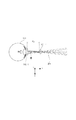
まず、本実施形形態に係る光断層撮像装置の概略構成について図1を用いて説明する。ここで、図1は、光断層撮像装置の側面図である。200は光断層撮像装置、900は前眼部の2次元像および断層画像を撮像するための測定光学系である光学ヘッド、950は光学ヘッドを図中xyz方向に不図示のモータを用いて移動可能とした移動部であるステージ部である。951は後述の分光器を内蔵するベース部である。なお、光学ヘッド900は、測定光の光路を含む光学部の一例であり、測定光学系の筺体である。また、ステージ部950は、被検査物に対して移動する光学部移動機構の一例である。
(Schematic configuration of the device)
First, a schematic configuration of the optical tomographic imaging apparatus according to the present embodiment will be described with reference to FIG. Here, FIG. 1 is a side view of the optical tomographic imaging apparatus. 200 is an optical tomographic imaging apparatus, 900 is an optical head that is a measurement optical system for capturing a two-dimensional image and a tomographic image of the anterior segment of the eye, and 950 is moved using a motor (not shown) in the xyz direction This is a stage unit that is a movable unit.
925はステージ部の制御部を兼ねるパソコンであり、ステージ部の制御とともに断層画像の構成等を行う。926は被検者情報記憶部を兼ね、断層撮像用のプログラムなどを記憶するハードディスクである。928は表示部であるモニタであり、929はパソコンへの指示を行う入力部であり、具体的にはキーボードとマウスから構成される。323は顎台であり、被検者の顎と額とを固定することで、被検者の眼(被検眼)の固定を促す。324は外部固視灯であり、被検者の眼を固視させるのに使用する。後述する内部固視灯と切り替えての使用が可能となっている。
Reference numeral 925 denotes a personal computer that also serves as a control unit for the stage unit, and performs tomographic image configuration and the like along with control of the stage unit. A
(測定光学系および分光器の構成)
本実施形態の測定光学系および分光器の構成について図2を用いて説明する。
(Configuration of measurement optical system and spectrometer)
The configuration of the measurement optical system and the spectroscope of this embodiment will be described with reference to FIG.
まず、光学ヘッド900部の内部について説明する。被検眼100に対向して対物レンズ101−1、101−2が設置され、その光軸上で反射ミラー102およびダイクロイックミラー103によってOCT光学系の光路L1、前眼部観察と内部固視灯用の光路L2とに波長帯域ごとに分岐される。
First, the inside of the
光路L2はさらに第3ダイクロイックミラー104によって前眼部観察用のCCD105および内部固視灯106への光路へと上記と同じく波長帯域ごとに分岐される。ここで101−3,107,108はレンズであり、107は固視灯および前眼部観察用の合焦調整のため不図示のモータによって駆動される。CCD105は不図示の前眼部観察用照明光の波長、具体的には780nm付近に感度を持つものである。一方、内部固視灯106は可視光を発生して被検者の固視を促すものである。
The optical path L2 is further branched for each wavelength band by the third
光路L1は前述の通りOCT光学系を成しており被検眼100の前眼部100−1の断層画像を撮像するためのものである。より具体的には断層画像を形成するための干渉信号を得るものである。光路L1には、レンズ101−4、ミラー113、光を被検眼100の前眼部100−1上で走査するためのXスキャナ114−1、Yスキャナ114−2が配置されている。さらに、115,116はレンズであり、そのうちのレンズ115は、光カプラー117に接続されているファイバー117−2から出射する光源118からの光を前眼部100−1上に合焦調整をするために不図示のモータによって駆動される。この合焦調整によって前眼部100−1からの光は同時にファイバー117−2先端にスポット状に結像されて入射されることとなる。なお、レンズ115は、OCTフォーカスレンズとも呼び、合焦レンズの一例である。
The optical path L1 forms the OCT optical system as described above, and is for capturing a tomographic image of the anterior segment 100-1 of the
次に、光源118からの光路と参照光学系、分光器の構成について説明する。
Next, the configuration of the optical path from the
118は光源、119はミラー、120は分散補償用ガラス、117は前述した光カプラー、117−1〜4は光カプラーに接続されて一体化しているシングルモードの光ファイバー、121はレンズ、180は分光器である。 118 is a light source, 119 is a mirror, 120 is a dispersion compensation glass, 117 is an optical coupler as described above, 117-1 to 4 are integrated with a single mode optical fiber, 121 is a lens, and 180 is a spectroscopic unit. It is a vessel.
これらの構成によってマイケルソン干渉計を構成している。光源118から出射された光は光ファイバー117−1を通じ光カプラー117を介して光ファイバー117−2側の測定光と光ファイバー117−3参照光とに分割される。測定光は前述のOCT光学系光路を通じ、観察対象である被検眼100の眼底に照射され、網膜による反射や散乱により同じ光路を通じて光カプラー117に到達する。
These configurations constitute a Michelson interferometer. The light emitted from the
一方、参照光は光ファイバー117−3、レンズ121、測定光と参照光の分散を合わせるために挿入された分散補償ガラス120を介して参照ミラー119に到達し反射される。そして同じ光路を戻り光カプラー117に到達する。光カプラー117によって、測定光と参照光は合波され干渉光となる。ここで、測定光の光路長と参照光の光路長とが所定の条件を満たす状態となったときに干渉を生じる。参照ミラー119は不図示のモータおよび駆動機構によって光軸方向に調整可能に保持され、前眼部100−1によって変わる測定光の光路長に参照光の光路長を合わせることが可能である。干渉光は光ファイバー117−4を介して分光器180に導かれる。
On the other hand, the reference light reaches the
分光器180はレンズ181、183、回折格子182、ラインセンサ184から構成される。光ファイバー117−4から出射された干渉光はレンズ181を介して略平行光となった後、回折格子182で分光され、レンズ183によってラインセンサ184に結像される。なお、当該ラインセンサ184は、本実施形態において干渉光を受光して該干渉光に応じた出力信号を発生、出力する受光素子の一例として示される。
The
次に、光源118の周辺について説明する。光源118は代表的な低コヒーレント光源であるSLD(Super Luminescent Diode)である。中心波長は855nm、波長バンド幅は約100nmである。ここで、バンド幅は、得られる断層画像の光軸方向の分解能に影響するため、重要なパラメータである。また、光源の種類は、ここではSLDを選択したが、低コヒーレント光が出射できればよく、ASE(Amplified Spontaneous Emission)等も用いることができる。中心波長は眼を測定することを鑑みると、近赤外光が適する。また、中心波長は得られる断層画像の横方向の分解能に影響するため、なるべく短波長であることが望ましい。双方の理由から中心波長を855nmとした。
Next, the periphery of the
本実施形態では干渉計としてマイケルソン干渉計を用いたが、マッハツェンダー干渉計を用いてもよい。測定光と参照光との光量差に応じて光量差が大きい場合にはマッハツェンダー干渉計を、光量差が比較的小さい場合にはマイケルソン干渉計を用いることが望ましい。 In this embodiment, a Michelson interferometer is used as the interferometer, but a Mach-Zehnder interferometer may be used. It is desirable to use a Mach-Zehnder interferometer when the light amount difference is large according to the light amount difference between the measurement light and the reference light, and a Michelson interferometer when the light amount difference is relatively small.
(断層画像の取得方法)
光断層撮像装置を用いた断層画像の取得方法について説明する。光断層撮像装置は、Xスキャナ114−1、Yスキャナ114−2を制御することで、被検眼100の前眼部100−1における所望部位の断層画像を取得することができる。
(Tomographic image acquisition method)
A method for acquiring a tomographic image using the optical tomographic imaging apparatus will be described. The optical tomographic imaging apparatus can acquire a tomographic image of a desired part in the anterior eye portion 100-1 of the
図3は、被検眼100に測定光201を照射し、前眼部100−1をx方向にスキャンを行っている様子を示している。前眼部100−1におけるx方向の撮像範囲から所定の撮像本数の情報をラインセンサ184で撮像する。x方向のある位置で得られるラインセンサ184上の輝度分布を高速フーリエ変換(FFT)し、該FFTで得られた線状の輝度分布をモニタに示すために濃度あるいはカラー情報に変換したものをAスキャン画像と呼ぶ。即ち、受光素子たるラインセンサ184において受光された干渉光により得られた出力信号に応じて、Aスキャン画像としての画像取得が為される。この複数のAスキャン画像を並べた2次元の画像をBスキャン画像と呼ぶ。1つのBスキャン画像を構築するための複数のAスキャン画像を取得した後、y方向のスキャン位置を移動させて再びx方向のスキャンを行うことにより、複数のBスキャン画像を得る。複数のBスキャン画像、あるいは複数のBスキャン画像から構築した3次元断層画像をモニタに表示することで検者が被検眼の診断に用いることができる。
FIG. 3 shows a state in which the eye to be examined 100 is irradiated with the measurement light 201 and the anterior eye portion 100-1 is scanned in the x direction. A
ここで、前眼部の断層画像を得る際の撮像範囲である画角は、後述する図4に示されるx方向のスキャン範囲Roに応じて通常は決定される。またこのスキャン範囲R0は、スキャナのスキャン角度θと対物レンズ101−1から被検眼前眼部までの撮影距離P0と、により決定される。即ち、撮像領域の大きさを変えたい場合には、スキャン角度θ或いは撮影距離P0を変更するが、撮影距離P0の変更は光学ヘッド900をZ軸方向に移動する等、測定光の光路長を変更することにより容易に実行できる。このため、本実施形態では光学ヘッド900を測定光の光路長を変更することにより撮影距離P0を変更することとし、これら構成を測定光光路長変更手段として定義する。なお、測定光の光路長を変更する構成は例示した本実施形態以外にも存在するが、本実施形態では測定光路長変更手段としてこれらを包括する概念として定義する。
Here, the angle of view, which is an imaging range when obtaining a tomographic image of the anterior segment, is normally determined according to a scan range Ro in the x direction shown in FIG. 4 to be described later. The scan range R0 is determined by the scan angle θ of the scanner and the photographing distance P0 from the objective lens 101-1 to the anterior eye portion to be examined. That is, when it is desired to change the size of the imaging region, the scan angle θ or the imaging distance P0 is changed. However, the change of the imaging distance P0 can be performed by changing the optical path length of the measurement light, for example, by moving the
測定光と参照光とを合波させて所望の干渉を得るためには、前述したようにこれら測定光の光路長と参照光の光路長とが所定の条件を満たすように連動することを要する。従って、撮影距離P0となる前眼部位置での測定光の光路長に応じて、参照光の光路長を変更するように参照ミラー119の移動が行われる。
In order to obtain the desired interference by combining the measurement light and the reference light, as described above, the optical path length of the measurement light and the optical path length of the reference light need to be linked so as to satisfy a predetermined condition. . Accordingly, the
当該参照ミラー119及びこれを移動させる構成は、本実施形態における参照光の光路長を変更する参照光光路長変更手段の一例として示される。また、先にも述べたように、合波光より干渉を得るために、参照光の光路長は測定光の光路長に応じて変更されることを要する。本実施形態においては、一例としてパソコン925において制御手段(「光路長連動手段」ともいう)として機能するモジュール領域により、測定光光路長変更手段による測定光の光路長の変更に連動させて、参照光光路長変更手段に参照光の光路長の変更を実行させることとしている。
The
図4は、撮影距離P0を変化させた時の前眼部撮像位置でのスキャン範囲を示した図と、その際の画角内に表示される断層画像を各々対応させて示している。撮影距離P0を変化させ且つこの変化に応じて参照ミラー119を移動させることにより、スキャン角度θを変えることなく前眼部の撮像範囲の大きさを変える事ができる。図4(b)のように被検眼と装置の距離を遠ざけるように撮影距離をPmaxまで変更し、且つ参照ミラー119を当該撮影距離Pmax相当位置まで移動することにより、前眼部を広いスキャン範囲Rmax(画角)で撮像できる。また、図4(c)のように被検眼と装置の距離を近づけるように撮影距離をPminまで変更し、且つ参照ミラー119を当該撮影距離Pmin相当位置まで移動することで、前眼部を拡大するようなスキャン範囲Rminで撮像できる。
FIG. 4 shows a diagram showing a scan range at the anterior ocular segment imaging position when the imaging distance P0 is changed, and a tomographic image displayed within the angle of view at that time. By changing the imaging distance P0 and moving the
(測定操作画面)
次に、本実施形態に係る測定操作画面について、図5と図6を用いて説明する。ここで、図5は、本実施形態に係る測定操作画面1000の一例を示した図である。また、図6は、本実施形態に係る測定操作画面1000の他の例を示した図である。
(Measurement operation screen)
Next, the measurement operation screen according to the present embodiment will be described with reference to FIGS. Here, FIG. 5 is a diagram illustrating an example of the
まず、1101は前眼観察用CCD105によって得られた前眼観察画面、1301は取得された断層画像を確認するための断層画像表示画面である。また、1001は被検眼の左右眼を切り替えるボタンであり、L、Rボタンを押すことにより、左右眼の初期位置に光学ヘッド900を移動する。1002はマウスカーソルであり、検者が入力部929に含まれるマウスを操作することによりこのマウスカーソル位置を動かす。本測定装置において、マウスカーソルの位置検出手段により、マウスカーソルの位置に応じてアライメント手段が変更できるように構成されている。マウスカーソルの位置検出手段は、マウスカーソルの表示画面上の画素位置からその位置を算出する。測定画面中には範囲を設けておき、設けた範囲とアライメント駆動の対応づけを予め設定しておく。それにより、設定した範囲の画素内にマウスカーソルがあるときには、その設定した範囲で定めたアライメントを行うことができる。またマウスによるアライメント操作は、マウスのホイールを回転させることにより行う。
First,
また、それぞれの画像の近傍に配置されているスライダは、調整を行うためのものである。スライダ1103は被検眼に対する撮影距離を指定するものでスライダを動かすのと連動して前眼観察画面内のキャラクタ1003の大きさが変わるようになっている。更に、キャラクタ1003の大きさは、前眼部の撮像範囲(画角)の大きさの変更と連動しており、前眼部観察用フォーカスレンズ107を所定位置へ移動する。当該フォーカスレンズ107は、本実施形態において前眼部に対する焦点合わせを実行するフォーカスレンズを含む前眼部観察手段の一例として示される。スライダ上限が前述した前眼部撮像範囲Rmaxに、スライダ下限が前眼部撮像範囲Rminに各々対応している。スライダ1203はOCTフォーカス調整を行うものである。OCTフォーカス調整は、前眼部に対する合焦調整を行うために、レンズ115を図示の方向に移動する調整である。また、これらのスライダは、それぞれの画像中においてマウスによるアライメント操作の際にも連動して動くようになっている。即ち、スライダ1203によるOCTフォーカス調整とは独立或いは連動し、更にパソコン925における制御手段(「合焦連動手段」ともいう)は、測定光光路長変更手段による測定光の光路長の変更に連動させて、前眼部に対する焦点合わせをOCTフォーカスレンズ115に実行させる。なお、前眼部観察手段による前眼部に対する合焦操作は、撮影距離の変更を伴う測定光の光路長の変更に応じて為されることを要する。本実施形態では、前述した制御手段(「前眼部用合焦連動手段」ともいう)が、測定光光路長変更手段による測定光の光路長の変更に連動させて、前眼部観察手段による前眼部に対する焦点合わせを実行させることとしている。
A slider arranged in the vicinity of each image is used for adjustment. A
また、図6は、図5に対して、スライダ1103を撮像範囲選択ボタン1004に置き換えたものである。このとき、標準(R0=6mm×6mm)、最大(Rmax=9mm×9mm)、最小(Rmin=3mm×3mm)が、各々設定されている。このとき、検者による撮像範囲選択ボタン1004のいずれかの選択に応じて、断層画像の撮像範囲の大きさを変更することができる。なお、前眼部画像1102が取得されていない状態で、検者が上記選択を行っても、上記撮像範囲の大きさを変更することができる。
FIG. 6 is obtained by replacing the
(前眼部の断層画像を取得するフロー)
次に、本実施形態に係るOCT装置を用いて前眼部の断層画像を取得するフローについて、図7を用いて説明する。ここで、図7は、本実施形態に係る測定フローを示した図であり、検者及びパソコン925の動作を示すフローチャートである。
(Flow for acquiring tomographic images of the anterior segment)
Next, a flow for acquiring a tomographic image of the anterior segment using the OCT apparatus according to the present embodiment will be described with reference to FIG. Here, FIG. 7 is a diagram illustrating a measurement flow according to the present embodiment, and is a flowchart illustrating the operations of the examiner and the personal computer 925.
まず、ステップS101において、パソコン925は、本フローを開始する。次に、ステップS102において、パソコン925による指示に応じて、前眼部画像1102を取得する。このとき、不図示の前眼部照明光は、被検眼100を照明した後、反射光は対物レンズ101−1、101−2を通過し、前述した光路L2を通過して、CCD105に結像される。CCD105に結像された前眼部画像は、図示しないCCD制御部で読み出し、増幅、A/D変換されて、演算部に入力される。演算部に入力された前眼像は、パソコン925に取り込まれる。
First, in step S101, the personal computer 925 starts this flow. Next, in step S102, an anterior
また、ステップS103において、検者は、パソコン925への指示を行う入力部929を用いて、所望の撮像範囲の大きさに変更する指示をスライダ1103に行う。このとき、スライダ1103のバーは画面上で移動する。この検者による指示に応じて、制御手段の一例であるパソコン925は、変更された大きさに対応する距離となるように、光学ヘッド900を光軸方向に移動する。また、ステップS104において、制御手段の一例であるパソコン925は、光学ヘッド900の移動に応じて、該測定光の光路長が変更した距離に対応する位置に参照ミラー119を移動する制御を行う。これにより、前眼部断層画像1301が撮影フレーム内に配置されるように、コヒーレンスゲートが調整される。なお、参照ミラー119の移動と一緒に、前眼部フォーカスレンズ107を移動しても良い。また、撮影範囲の大きさの変更の指示に応じて、光学ヘッド900の移動および参照ミラー119の移動を連動して実行するが、このとき、合焦位置を変更するためにOCTフォーカスレンズ115の移動を連動して実行しても良い。また、参照ミラー119の移動を連動させる代わりに、OCTフォーカスレンズ115の移動を連動させても良い。このとき、後述するステップ106を省略することができる。また、各部材を同時に移動しても良いし、各部材の移動タイミングに時間差があっても良い。
In step S103, the examiner gives an instruction to the
また、ステップS105において、検者の指示に応じて、制御手段の一例であるパソコン925は、前眼部に対して光学ヘッド900を移動して、前眼部に対する光学ヘッド900の位置合わせ(アライメント)を行う。なお、光学ヘッド900に対して被検者の顔受け部等を移動することにより、上記位置合わせを行っても良い。また、検者の手動による操作以外に、光学ヘッド900が自動で移動しても良い。具体的には、CCD105により撮像された前眼画像から画像処理により被検眼100の瞳孔位置を検出する。これにより、該検出された瞳孔位置に基づいて光断層撮像装置と被検眼100とのアライメント位置関係を知ることができる。そして、検出した被検眼100の瞳孔位置が理想位置となるように、光学ヘッド900を不図示のXYZステージを駆動することができる。また、このとき、断層画像撮影中に前眼部をトラッキングすることで、検者は常に被検眼100の前眼部を監視できるため、利便性を向上することができる。
In step S105, the personal computer 925, which is an example of a control unit, moves the
また、ステップ106において、検者は、入力部929を用いて、前眼部断層画像1301の合焦位置を変更する指示をスライダ1203に行う。このとき、スライダ1203のバーは画面上で移動する。この検者による指示に応じて、制御手段の一例であるパソコン925は、OCTフォーカスレンズ115が移動する制御を行う。これにより、OCTフォーカスを調整することができる。また、ステップ107において、検者は、入力部929を用いて、撮像ボタン1005を押す。この検者による指示に応じて、制御手段の一例であるパソコン925は、前眼部の断層画像を取得する制御を行う。また、ステップ108において、表示制御手段の一例であるパソコン925は、前眼部の断層画像をモニタ928に表示させる。なお、ステップ108において、パソコン925は、前眼部の断層画像を補正し、該補正された画像をモニタ928に表示させても良い。そして、ステップ109において、本フローを終了する。
In
ここで、ステップ108において取得された断層画像は、例えば、標準とした撮影距離P0の場合に得られる断層画像に対し、同一広さ画面内においてより広範囲な部位の画像、或いは狭い範囲の部位の画像となっている場合がある。後述するように、当該補正は、撮像されたこれらの画像における部位が撮影距離P0で得られる部位と同じ大きさで表示されるように、表示範囲(画角)を拡大或いは縮小する操作となる。以上の操作はパソコン925において画像の表示様式を補正、変更する画像補正手段として機能するモジュール領域により実行される。また、表示手段上において撮影範囲の大きさの変更を指示するためのカーソル等の表示或いはその表示形態は、制御手段に包含される表示制御手段として機能するモジュール領域により実行される。
Here, the tomographic image acquired in
実際には、前眼部断層像は、標準距離より撮影距離が遠ければ断層深さが変化せずに左右方向のみ狭くなり、標準距離より撮影距離が狭ければ左右方向のみ広くなる。図8は、前眼部断層像の表示画像を補正した例である。図8(1a)にて撮影距離P0に対応した左右方向の視野x0が、撮影距離Pmaxと遠くなると左右方向の視野xmへと狭くなる。図8(2b)のように左右方向の視野xmを視野x0へ変換して表示する事は既知の画像処理方法により容易に可能である。撮影距離Pminについても、図8(3b)のように画像を処理して表示できる。更に、図8(2b)及び図8(3b)の画像を元に各種計測を行っても良いし、撮影距離Pと左右方向の視野xとの比率をかける事により図8(2a)、図8(3a)の元図を使用して各種計測を行っても良い。 Actually, the tomographic image of the anterior segment is narrowed only in the left-right direction without changing the tomographic depth if the photographing distance is farther than the standard distance, and widened only in the left-right direction if the photographing distance is narrower than the standard distance. FIG. 8 shows an example in which the display image of the anterior segment tomogram is corrected. In FIG. 8 (1a), the horizontal field of view x0 corresponding to the shooting distance P0 is narrowed to the horizontal field of view xm as the shooting distance Pmax is increased. As shown in FIG. 8 (2b), it is possible to easily convert the horizontal visual field xm into the visual field x0 and display it by a known image processing method. The shooting distance Pmin can also be processed and displayed as shown in FIG. 8 (3b). Further, various measurements may be performed based on the images of FIGS. 8 (2b) and 8 (3b), and FIG. 8 (2a) and FIG. Various measurements may be performed using the original drawing 8 (3a).
以上説明したように、本実施形態の光断層撮像装置においては、検者が様々な撮像範囲を指定し撮像可能な装置を提供することができる。即ち、光学系の性能を保ったまま様々な視野かつ高解像度の光断層撮像装置を提供することができる。また同時に、被検眼と装置の作動距離を変える事ができるので、被検者の状況に応じて作動距離を長くして撮影する事で被検者の負担を和らげる事ができる。 As described above, in the optical tomographic imaging apparatus according to the present embodiment, it is possible to provide an apparatus that allows an examiner to specify various imaging ranges and perform imaging. That is, it is possible to provide an optical tomographic imaging apparatus with various fields of view and high resolution while maintaining the performance of the optical system. At the same time, since the working distance between the eye and the device can be changed, the burden on the subject can be reduced by taking an image with a longer working distance according to the condition of the subject.
[第2の実施形態:測定光の光路長を短くする場合には光路長の変更速度を遅くする]
次に、第2の実施形態に係る光断層撮像装置(OCT装置)について、図9を用いて説明する。第1の実施形態では、光学ヘッド900を被検眼に近づけることで撮影距離P0を小さくして、測定光の光路長を短くすることができる。この場合、光学ヘッド900が被検眼により近づくため、光学ヘッド900と被検眼が接触する可能性が増す。そこで、本実施形態では、制御手段の一例であるパソコン925が、断層画像の撮像範囲を狭くする(拡大画像を取得する)指示の場合には、測定光の光路長を短くするように且つ該撮像範囲を広くする(広角画像を取得する)指示の場合よりも該測定光の光路長の変更速度を遅くするように、測定光光路長変更手段を制御する。例えば、光学ヘッド900と被検眼が接触する可能性を減らすため、光学ヘッド900が被検眼に対して近づく場合、移動速度を遠ざける場合よりも、光学ヘッド900の移動速度を遅くする。
Second Embodiment: to slow the change speed of the optical path length of the optical path length of the measuring light if Shorten]
Next, an optical tomographic imaging apparatus (OCT apparatus) according to the second embodiment will be described with reference to FIG. In the first embodiment, by reducing the photographing distance P0 by approximating the
具体的には、制御手段の一例であるパソコン925が、パソコン925への指示を行う入力部929(指示手段の一例であり、操作部とも呼ぶ)により断層画像の撮像範囲を狭くする指示の場合には、撮像範囲を広くする指示の場合よりも、測定光の光路長の変更速度を遅くして測定光の光路長を短くするように測定光光路長変更手段を制御する。これにより、検者は、光学ヘッド900が移動しているときに、光学ヘッド900が被検眼に接触するか否かを容易に判断することができるため、安全性を高めることができる。
Specifically, when the personal computer 925, which is an example of a control unit, issues an instruction to narrow the tomographic image capturing range by an input unit 929 (which is an example of an instruction unit and is also referred to as an operation unit) that instructs the personal computer 925. the, than in the case of an instruction to increase the imaging range, and controls the measuring light optical path length changing means the optical path length of the measurement light at slow changing speed of the optical path length of the measuring light to Shorten so. As a result, the examiner can easily determine whether or not the
また、検者によって、光学ヘッド900と被検眼とが接触する可能性があると判断された場合には、光学ヘッド900の移動をキャンセルできるように、図9のようなキャンセルボタン913をスライダ1103付近に表示させても良い。スライダ1103の縮小を指示する位置に近いことで、直ちに光学ヘッド900の移動をキャンセルすることができる。これにより、光学ヘッド900と被検眼の接触を回避することができる。また、キャンセルボタン913は、所定の撮影距離Pに戻るためのボタンとしてもよい。光学ヘッド900が被検眼に近づきすぎた場合には、接触を回避するため、光学ヘッド900を被検眼と接触しない所定位置まで移動することもできる。
When the examiner determines that there is a possibility that the
なお、測定光の光路長を短くする前に、測定光の光路長が長いところ、すなわち、被検眼から装置が遠いところで、一旦、被検眼の広範囲の断層画像を取得してから、ユーザが狭い詳細な撮像範囲を指示し、装置を被検眼に近づけていく手法でも良い。具体的には、図7のステップ102において、撮影距離Pは、標準とした撮影距離P0よりも長い距離、すなわち、被検眼から遠い位置とする。被検眼から遠い位置で撮影することで、前眼部画像1102では前眼部の広角画像を得ることができる。これにより、検者は前眼部の広い範囲を確認することができる。その後に、ステップ103の撮影範囲の指定を行うことで、詳細な範囲の撮影を少ないステップによって、実行することができる。
Incidentally, the optical path length of the measuring light before Shorten where the optical path length of the measurement light is long, i.e., at device from the eye is far, once after obtaining a wide range of a tomographic image of the eye, the user May be a method of instructing a narrow and detailed imaging range and bringing the apparatus close to the eye to be examined. Specifically, in
[第3の実施形態:最大の撮像範囲と最小の撮像範囲とを予め表示]
次に、第3の実施形態に係る光断層撮像装置(OCT装置)について、図9を用いて説明する。第1の実施形態では、スライダ1103は被検眼に対する撮影距離を指定するものであり、スライダを動かすのと連動して前眼観察画面内のキャラクタ1003の大きさが変わるようになっている。つまり、撮影距離Pは、スライダ1103の位置や、キャラクタ1003の大きさによって認識することができる。一方で撮像範囲は、標準(R0=6mm)、最大(Rmax=9mm)、最小(Rmin=3mm)とあらかじめ決められている。
[Third Embodiment: Preliminary Display of Maximum Imaging Range and Minimum Imaging Range]
Next, an optical tomographic imaging apparatus (OCT apparatus) according to a third embodiment will be described with reference to FIG. In the first embodiment, the
本実施形態では、これらの予め決められている撮影範囲を、拡大限界範囲909に対応する位置906や縮小限界範囲908に対応する位置907のように、スライダ1103と同じ画面上に表示させておくことで、検者は撮影範囲の大きさの限界を知ることができる。また、縮小限界範囲908や拡大限界範囲909のように、キャラクタ1003と同じ観察画面1101上に表示するもできる。ここで、縮小限界範囲908は、最大撮影距離Pmaxに対応する撮像範囲である。最大撮影距離Pmaxは、OCTフォーカスレンズ115や参照ミラー119の駆動限界等により決定される。一方、拡大限界範囲909は、最小撮影距離Pminに対応する撮像範囲である。最小撮影距離Pminは、OCTフォーカスレンズ115や参照ミラー119の駆動限界に加えて、被検眼に対して光学ヘッド900が接触する観点から、被検眼に対する安全性を確保可能な距離によっても決定される。なお、縮小限界範囲908や拡大限界範囲909は、撮像範囲の限界の範囲を示す表示形態の一例である。
In the present embodiment, these predetermined photographing ranges are displayed on the same screen as the
また、縮小限界範囲908と拡大限界範囲909は、スライダ1103やキャラクタ1003とは異なる線種や色で表示することにより、検者の視認性を向上させることができる。なお、拡大限界範囲909は、上述したように、光学ヘッド900が被検眼に最も近付いた状態を示している。このため、光学ヘッド900と検者との接触の観点から、縮小限界範囲908に比べて視認性の高い赤色や太線で表示させることが好ましい。このように、拡大や縮小できる限界を画面表示させておくことにより、検者は撮影可能な範囲を予め認識することができる。なお、表示手段の一例であるパソコン925は、撮像範囲の大きさの変更を指示する表示形態(例えば、スライダ1103)における撮像範囲の限界の範囲外に撮像範囲の大きさの変更が指示された場合には、警告を示す表示形態を表示手段に表示させることが好ましい。ここで、撮像範囲の限界の範囲外とは、例えば、スライダ1103における拡大限界範囲909に対応する位置906の上側、スライダ1103における縮小限界範囲908に対応する位置907の下側のことである。また、警告を示す表示形態とは、例えば、撮像範囲の大きさを変更できないことを示すメッセージである。
Further, the
[第4の実施形態:プレビュー画像を表示して決定後に移動開始]
次に、第4の実施形態に係る光断層撮像装置(OCT装置)について、図9を用いて説明する。第1の実施形態では、測定画面のスライダ1103や撮像範囲選択ボタン1004を用いて、撮影範囲を決めている。本実施形態では、図7のS103において撮影範囲を指定したら、まず、プレビュー画面910を表示し、プレビュー画像911、912を確認できるようにする。図9のプレビュー画像911、912はそれぞれ、拡大させたときのプレビュー画像、縮小させたときのプレビュー画像である。このとき、撮影距離Pは変更せずに、すでに得られている観察画像を基にして、画像データをトリミングや表示倍率の変更処理することによって作成する。したがってプレビュー画像は、本来得られる画像よりも画質が劣る。また、縮小させたときのプレビュー画像912の外側は、得られていない。したがって、外側は、黒表示にしたり、元画像をぼやかしたりして表示させてもよい。
[Fourth Embodiment: Displaying Preview Image and Starting Movement after Determination]
Next, an optical tomographic imaging apparatus (OCT apparatus) according to a fourth embodiment will be described with reference to FIG. In the first embodiment, the imaging range is determined using the
また、プレビュー画面910の確認により、撮影範囲が所望の範囲であると判断された場合には、決定ボタン905によって、撮像範囲の拡大や縮小を実際に行うことを決定する。決定された後、制御部は光学ヘッドを移動させ、撮影距離Pの変更を実行する。本実施形態によれば、撮像範囲の指定を間違えた場合の遅延を防止することができる。
If it is determined by checking the
[その他の実施形態]
また、本実施形態は、以下の処理を実行することによっても実現される。即ち、上述した実施形態の機能を実現するソフトウェア(プログラム)を、ネットワーク又は各種記憶媒体を介してシステム或いは装置に供給し、そのシステム或いは装置のコンピュータ(またはCPUやMPU等)がプログラムを読み出して実行する処理である。
[Other Embodiments]
Moreover, this embodiment is implement | achieved also by performing the following processes. That is, software (program) that realizes the functions of the above-described embodiments is supplied to a system or apparatus via a network or various storage media, and a computer (or CPU, MPU, or the like) of the system or apparatus reads the program. It is a process to be executed.
なお、本発明は、上記の実施形態に限定されるものではなく、本実施形態の趣旨を逸脱しない範囲内において、種々の変形、変更して実施することができる。例えば、上記の実施例では、被測定物が眼の場合について述べているが、眼以外の皮膚や臓器等の被測定物に本実施形態を適用することも可能である。この場合、本発明は、眼科装置以外の、例えば内視鏡等の医療機器としての態様を有する。従って上述した被検眼は被検査物として理解されることが好ましい。 In addition, this invention is not limited to said embodiment, In the range which does not deviate from the meaning of this embodiment, a various deformation | transformation and change can be implemented. For example, in the above-described example, the case where the object to be measured is the eye is described, but the present embodiment can also be applied to the object to be measured such as skin or organ other than the eye. In this case, the present invention has an aspect as a medical device such as an endoscope other than the ophthalmologic apparatus. Therefore, it is preferable that the above-described eye to be examined is understood as an object to be examined.
Claims (18)
前記測定光の光路長を変更する測定光光路長変更手段と、
前記断層画像の撮像範囲の大きさを指示する指示手段と、
前記撮像範囲を狭くする指示の場合には、前記測定光の光路長を標準距離に対して短くするように、且つ前記撮像範囲を広くする指示の場合よりも前記測定光の光路長を変更する速度を遅くするように、前記測定光光路長変更手段を制御する制御手段と、
を有することを特徴とする光断層撮像装置。 An optical tomographic imaging apparatus that obtains a tomographic image of the anterior segment based on light obtained by combining the return beam from the anterior segment of the subject eye irradiated with the measurement beam and the reference beam corresponding to the measurement beam There,
Measuring light path length changing means for changing the optical path length of the measuring light;
Instruction means for instructing the size of the imaging range of the tomographic image;
In the case of an instruction to narrow the imaging range, the optical path length of the measuring light is changed so as to shorten the optical path length of the measuring light with respect to a standard distance and more than in the case of an instruction to widen the imaging range. Control means for controlling the measuring light path length changing means so as to reduce the speed;
An optical tomographic imaging apparatus comprising:
前記制御手段が、前記撮像範囲を狭くする指示の場合には、前記前眼部に対して前記光学部を近づけるように、且つ前記撮像範囲を広くする指示の場合よりも前記光学部の移動速度を遅くするように、前記光学部移動機構を制御することを特徴とする請求項1に記載の光断層撮像装置。 The measurement light path length changing means has an optical part moving mechanism that moves an optical part including the optical path of the measurement light with respect to the anterior eye part,
When the control means is instructed to narrow the imaging range, the moving speed of the optical unit is larger than that in the case of an instruction to bring the optical unit closer to the anterior eye part and widen the imaging range. The optical tomographic imaging apparatus according to claim 1, wherein the optical unit moving mechanism is controlled so as to slow down the speed.
前記拡大限界範囲を示す表示形態は、前記縮小限界範囲を示す表示形態に対して視認性の高い表示形態であることを特徴とする請求項3に記載の光断層撮像装置。 The display control means is displayed on the display means in a state in which a display form indicating the expansion limit range of the imaging range and a display form indicating the reduction limit range of the imaging range are superimposed on the image of the anterior eye part,
The optical tomographic imaging apparatus according to claim 3, wherein the display form indicating the enlargement limit range is a display form having higher visibility than the display form indicating the reduction limit range.
前記指示手段が、操作手段による操作に応じて前記変更を指示することを特徴とする請求項3または4に記載の光断層撮像装置。 The display control means causes the display means to display a display form for inputting an instruction to change the size of the imaging range of the tomographic image;
The optical tomography apparatus according to claim 3, wherein the instruction unit instructs the change according to an operation by an operation unit.
前記制御手段が、前記指示手段による指示に応じて、前記測定光光路長変更手段と前記参照光光路長変更手段とを連動させて制御することを特徴とする請求項1乃至7の何れか一項に記載の光断層撮像装置。 Reference light path length changing means for changing the optical path length of the reference light is further included,
8. The control unit according to claim 1, wherein the control unit controls the measurement light optical path length changing unit and the reference light optical path length changing unit in conjunction with each other in accordance with an instruction from the instruction unit. The optical tomographic imaging apparatus according to Item.
前記制御手段が、前記指示手段による指示に応じて、前記測定光光路長変更手段と前記移動手段とを連動させて制御することを特徴とする請求項1乃至8の何れか一項に記載の光断層撮像装置。 A moving unit that moves a focusing lens that focuses the measurement light with respect to the anterior eye portion along an optical path;
9. The control unit according to claim 1, wherein the control unit controls the measurement light path length changing unit and the moving unit in conjunction with each other in accordance with an instruction from the instruction unit. 10. Optical tomography device.
前記測定光光路長変更手段は、前記対物レンズと前記前眼部との距離を変更することにより、前記測定光の光路長を変更することを特徴とする請求項1乃至9の何れか一項に記載の光断層撮像装置。 An objective lens provided in the optical path of the measurement light;
10. The measurement light path length changing unit changes the optical path length of the measurement light by changing a distance between the objective lens and the anterior eye part. An optical tomographic imaging apparatus according to 1.
前記前眼部において前記測定光を走査する走査手段と、
前記対物レンズと前記前眼部との距離が長くなると前記前眼部における測定光の走査範囲が広くなり、且つ前記対物レンズと前記前眼部との距離が短くなると前記前眼部における前記測定光の走査範囲が狭くなるように、前記測定光を前記前眼部に照射する照射手段と、
を有することを特徴とする請求項1乃至9の何れか一項に記載の光断層撮像装置。 An objective lens provided in the optical path of the measurement light;
Scanning means for scanning the measurement light in the anterior eye part;
When the distance between the objective lens and the anterior segment increases, the scanning range of the measurement light in the anterior segment increases, and when the distance between the objective lens and the anterior segment decreases, the measurement at the anterior segment. Irradiating means for irradiating the anterior ocular segment with the measurement light so that a light scanning range is narrowed;
The optical tomographic imaging apparatus according to claim 1, wherein the optical tomographic imaging apparatus is provided.
前記断層画像の撮像範囲の大きさを指示する工程と、
前記撮像範囲を狭くする指示の場合には、前記測定光の光路長を標準距離に対して短くするように、且つ前記撮像範囲を広くする指示の場合よりも前記測定光の光路長を変更する速度を遅くするように、前記測定光の光路長を変更する測定光光路長変更手段を制御する工程と、
を有することを特徴とする光断層撮像装置の制御方法。 An optical tomographic imaging apparatus that acquires a tomographic image of the anterior eye part based on light obtained by combining return light from the anterior eye part of the subject eye irradiated with measurement light and reference light corresponding to the measurement light A control method,
Instructing the size of the imaging range of the tomographic image;
In the case of an instruction to narrow the imaging range, the optical path length of the measuring light is changed so as to shorten the optical path length of the measuring light with respect to a standard distance and more than in the case of an instruction to widen the imaging range. Controlling the measurement light path length changing means for changing the optical path length of the measurement light so as to reduce the speed;
A method for controlling an optical tomographic imaging apparatus.
前記制御する工程において、前記撮像範囲を狭くする指示の場合には、前記前眼部に対して前記光学部を近づけるように、且つ前記撮像範囲を広くする指示の場合よりも前記光学部の移動速度を遅くするように、前記光学部移動機構を制御することを特徴とする請求項12に記載の光断層撮像装置の制御方法。 The measurement light path length changing means has an optical part moving mechanism that moves an optical part including the optical path of the measurement light with respect to the anterior eye part,
In the step of controlling, in the case of an instruction to narrow the imaging range, the optical unit is moved more than in the case of an instruction to bring the optical unit closer to the anterior eye part and to widen the imaging range. to slow the speed control method of the optical tomographic imaging apparatus according to claim 1 2, wherein the controller controls the optical unit moving mechanism.
前記拡大限界範囲を示す表示形態は、前記縮小限界範囲を示す表示形態に対して視認性の高い表示形態であることを特徴とする請求項14に記載の光断層撮像装置の制御方法。 In the step of displaying on the display means, a display form showing the enlargement limit range of the imaging range and a display form showing the reduction limit range of the imaging range are displayed on the display means in a state of being superimposed on the image of the anterior eye part. And
The display form indicating the enlargement limit range, the control method of the optical tomographic imaging apparatus according to claim 1 4, characterized in that the high display forms of visibility to the view showing the reduced limits.
前記指示する工程において、操作手段による操作に応じて前記変更を指示することを特徴とする請求項14または15に記載の光断層撮像装置の制御方法。 In the step of displaying on the display unit, a display form for inputting an instruction to change the size of the imaging range of the tomographic image is displayed on the display unit,
In the step of the instruction, the control method of the optical tomographic imaging apparatus according to claim 1 4 or 1 5, characterized by instructing the change in response to operation by the operation means.
Priority Applications (3)
| Application Number | Priority Date | Filing Date | Title |
|---|---|---|---|
| JP2013017657A JP6188339B2 (en) | 2013-01-31 | 2013-01-31 | Optical tomographic imaging apparatus and control method thereof |
| CN201410042757.7A CN103961057B (en) | 2013-01-31 | 2014-01-29 | Optical sectioning imaging equipment and control method thereof |
| US14/167,802 US9277860B2 (en) | 2013-01-31 | 2014-01-29 | Optical tomographic imaging apparatus and method for controlling the same |
Applications Claiming Priority (1)
| Application Number | Priority Date | Filing Date | Title |
|---|---|---|---|
| JP2013017657A JP6188339B2 (en) | 2013-01-31 | 2013-01-31 | Optical tomographic imaging apparatus and control method thereof |
Publications (3)
| Publication Number | Publication Date |
|---|---|
| JP2014147499A JP2014147499A (en) | 2014-08-21 |
| JP2014147499A5 JP2014147499A5 (en) | 2016-04-28 |
| JP6188339B2 true JP6188339B2 (en) | 2017-08-30 |
Family
ID=51222572
Family Applications (1)
| Application Number | Title | Priority Date | Filing Date |
|---|---|---|---|
| JP2013017657A Expired - Fee Related JP6188339B2 (en) | 2013-01-31 | 2013-01-31 | Optical tomographic imaging apparatus and control method thereof |
Country Status (3)
| Country | Link |
|---|---|
| US (1) | US9277860B2 (en) |
| JP (1) | JP6188339B2 (en) |
| CN (1) | CN103961057B (en) |
Families Citing this family (6)
| Publication number | Priority date | Publication date | Assignee | Title |
|---|---|---|---|---|
| JP6552200B2 (en) * | 2015-01-09 | 2019-07-31 | キヤノン株式会社 | Optical tomographic imaging apparatus, control method thereof, and program |
| EP3675709B1 (en) | 2017-11-07 | 2023-07-26 | Notal Vision Ltd. | Systems for alignment of ophthalmic imaging devices |
| JP7330993B2 (en) | 2017-11-07 | 2023-08-22 | ノータル ビジョン リミテッド | Retinal imaging device and related method |
| JP6934811B2 (en) * | 2017-11-16 | 2021-09-15 | 株式会社ミツトヨ | Three-dimensional measuring device |
| US10595722B1 (en) | 2018-10-03 | 2020-03-24 | Notal Vision Ltd. | Automatic optical path adjustment in home OCT |
| US10653311B1 (en) | 2019-06-12 | 2020-05-19 | Notal Vision Ltd. | Home OCT with automatic focus adjustment |
Family Cites Families (9)
| Publication number | Priority date | Publication date | Assignee | Title |
|---|---|---|---|---|
| DE3878123T2 (en) * | 1987-09-30 | 1993-06-17 | Canon Kk | DEVICE FOR Ophthalmology. |
| JP4996917B2 (en) * | 2006-12-26 | 2012-08-08 | 株式会社トプコン | Optical image measurement device and program for controlling optical image measurement device |
| JP5179102B2 (en) * | 2007-06-29 | 2013-04-10 | 株式会社ニデック | Scanning laser ophthalmoscope and wide-angle lens attachment for scanning laser ophthalmoscope |
| US20090141237A1 (en) * | 2007-11-02 | 2009-06-04 | Bioptigen, Inc. | Integrated Optical Coherence Imaging Systems for Use in Ophthalmic Applications and Related Methods and Computer Program Products |
| JP5231802B2 (en) * | 2007-12-29 | 2013-07-10 | 株式会社ニデック | Ophthalmic imaging equipment |
| US8419186B2 (en) * | 2009-09-30 | 2013-04-16 | Nidek Co., Ltd. | Fundus observation apparatus |
| JP5545630B2 (en) | 2010-01-21 | 2014-07-09 | 株式会社ニデック | Ophthalmic imaging equipment |
| JP5289496B2 (en) * | 2011-03-31 | 2013-09-11 | キヤノン株式会社 | Ophthalmic equipment |
| US10702209B2 (en) * | 2012-10-24 | 2020-07-07 | Amo Development, Llc | Graphical user interface for laser eye surgery system |
-
2013
- 2013-01-31 JP JP2013017657A patent/JP6188339B2/en not_active Expired - Fee Related
-
2014
- 2014-01-29 CN CN201410042757.7A patent/CN103961057B/en active Active
- 2014-01-29 US US14/167,802 patent/US9277860B2/en not_active Expired - Fee Related
Also Published As
| Publication number | Publication date |
|---|---|
| US9277860B2 (en) | 2016-03-08 |
| CN103961057A (en) | 2014-08-06 |
| US20140211159A1 (en) | 2014-07-31 |
| JP2014147499A (en) | 2014-08-21 |
| CN103961057B (en) | 2016-04-06 |
Similar Documents
| Publication | Publication Date | Title |
|---|---|---|
| JP5210442B1 (en) | Optical tomographic imaging apparatus and control method | |
| JP5210443B1 (en) | Optical tomographic imaging apparatus and control method | |
| JP6551081B2 (en) | Ophthalmic imaging apparatus and ophthalmologic imaging program | |
| US8967804B2 (en) | Ophthalmic apparatus, ophthalmic apparatus control method and storage medium | |
| JP6184113B2 (en) | Optical tomographic imaging apparatus and control method thereof | |
| JP6300443B2 (en) | Optical tomographic imaging apparatus and control method thereof | |
| JP5220156B2 (en) | Medical devices and systems | |
| JP6188339B2 (en) | Optical tomographic imaging apparatus and control method thereof | |
| JP6415030B2 (en) | Image processing apparatus, image processing method, and program | |
| US9538913B2 (en) | Ophthalmic system | |
| JPWO2013085042A1 (en) | Fundus observation device | |
| JP6057619B2 (en) | Ophthalmic apparatus and method for controlling ophthalmic apparatus | |
| JP6308723B2 (en) | CONTROL DEVICE, ITS OPERATION METHOD, AND PROGRAM | |
| JP5766225B2 (en) | Optical tomographic imaging apparatus and control method | |
| JP6701250B2 (en) | Ophthalmic photographing apparatus, control method thereof, and program | |
| JP2016123722A (en) | Examination apparatus and control method for examination apparatus | |
| JP6635716B2 (en) | Display control device, display control method and program | |
| JP2016123481A (en) | Ophthalmologic apparatus, ophthalmologic system, and ophthalmologic apparatus control method | |
| JP2019115762A (en) | Examination apparatus and control method for examination apparatus |
Legal Events
| Date | Code | Title | Description |
|---|---|---|---|
| A521 | Request for written amendment filed |
Free format text: JAPANESE INTERMEDIATE CODE: A523 Effective date: 20160116 |
|
| A621 | Written request for application examination |
Free format text: JAPANESE INTERMEDIATE CODE: A621 Effective date: 20160116 |
|
| A521 | Request for written amendment filed |
Free format text: JAPANESE INTERMEDIATE CODE: A523 Effective date: 20160314 |
|
| A977 | Report on retrieval |
Free format text: JAPANESE INTERMEDIATE CODE: A971007 Effective date: 20161027 |
|
| A131 | Notification of reasons for refusal |
Free format text: JAPANESE INTERMEDIATE CODE: A131 Effective date: 20161115 |
|
| A521 | Request for written amendment filed |
Free format text: JAPANESE INTERMEDIATE CODE: A523 Effective date: 20170113 |
|
| TRDD | Decision of grant or rejection written | ||
| A01 | Written decision to grant a patent or to grant a registration (utility model) |
Free format text: JAPANESE INTERMEDIATE CODE: A01 Effective date: 20170704 |
|
| A61 | First payment of annual fees (during grant procedure) |
Free format text: JAPANESE INTERMEDIATE CODE: A61 Effective date: 20170801 |
|
| R151 | Written notification of patent or utility model registration |
Ref document number: 6188339 Country of ref document: JP Free format text: JAPANESE INTERMEDIATE CODE: R151 |
|
| LAPS | Cancellation because of no payment of annual fees |