JP6187807B2 - Ball screw device - Google Patents

Ball screw device Download PDF

Info

Publication number
JP6187807B2
JP6187807B2 JP2013107273A JP2013107273A JP6187807B2 JP 6187807 B2 JP6187807 B2 JP 6187807B2 JP 2013107273 A JP2013107273 A JP 2013107273A JP 2013107273 A JP2013107273 A JP 2013107273A JP 6187807 B2 JP6187807 B2 JP 6187807B2
Authority
JP
Japan
Prior art keywords
ball
ball nut
cylinder
peripheral surface
path
Prior art date
Legal status (The legal status is an assumption and is not a legal conclusion. Google has not performed a legal analysis and makes no representation as to the accuracy of the status listed.)
Expired - Fee Related
Application number
JP2013107273A
Other languages
Japanese (ja)
Other versions
JP2014199132A (en
Inventor
田代 明義
明義 田代
奈保子 尾崎
奈保子 尾崎
Current Assignee (The listed assignees may be inaccurate. Google has not performed a legal analysis and makes no representation or warranty as to the accuracy of the list.)
JTEKT Corp
Original Assignee
JTEKT Corp
Priority date (The priority date is an assumption and is not a legal conclusion. Google has not performed a legal analysis and makes no representation as to the accuracy of the date listed.)
Filing date
Publication date
Application filed by JTEKT Corp filed Critical JTEKT Corp
Priority to JP2013107273A priority Critical patent/JP6187807B2/en
Priority to EP14158024.1A priority patent/EP2778476B1/en
Priority to CN201410081842.4A priority patent/CN104048010B/en
Priority to US14/206,594 priority patent/US9416856B2/en
Publication of JP2014199132A publication Critical patent/JP2014199132A/en
Application granted granted Critical
Publication of JP6187807B2 publication Critical patent/JP6187807B2/en
Expired - Fee Related legal-status Critical Current
Anticipated expiration legal-status Critical

Links

Images

Classifications

    • FMECHANICAL ENGINEERING; LIGHTING; HEATING; WEAPONS; BLASTING
    • F16ENGINEERING ELEMENTS AND UNITS; GENERAL MEASURES FOR PRODUCING AND MAINTAINING EFFECTIVE FUNCTIONING OF MACHINES OR INSTALLATIONS; THERMAL INSULATION IN GENERAL
    • F16HGEARING
    • F16H25/00Gearings comprising primarily only cams, cam-followers and screw-and-nut mechanisms
    • F16H25/18Gearings comprising primarily only cams, cam-followers and screw-and-nut mechanisms for conveying or interconverting oscillating or reciprocating motions
    • F16H25/20Screw mechanisms
    • F16H25/22Screw mechanisms with balls, rollers, or similar members between the co-operating parts; Elements essential to the use of such members
    • F16H25/2204Screw mechanisms with balls, rollers, or similar members between the co-operating parts; Elements essential to the use of such members with balls
    • F16H25/2214Screw mechanisms with balls, rollers, or similar members between the co-operating parts; Elements essential to the use of such members with balls with elements for guiding the circulating balls
    • FMECHANICAL ENGINEERING; LIGHTING; HEATING; WEAPONS; BLASTING
    • F16ENGINEERING ELEMENTS AND UNITS; GENERAL MEASURES FOR PRODUCING AND MAINTAINING EFFECTIVE FUNCTIONING OF MACHINES OR INSTALLATIONS; THERMAL INSULATION IN GENERAL
    • F16HGEARING
    • F16H25/00Gearings comprising primarily only cams, cam-followers and screw-and-nut mechanisms
    • F16H25/18Gearings comprising primarily only cams, cam-followers and screw-and-nut mechanisms for conveying or interconverting oscillating or reciprocating motions
    • F16H25/20Screw mechanisms
    • F16H25/22Screw mechanisms with balls, rollers, or similar members between the co-operating parts; Elements essential to the use of such members
    • F16H25/2247Screw mechanisms with balls, rollers, or similar members between the co-operating parts; Elements essential to the use of such members with rollers
    • F16H2025/2271Screw mechanisms with balls, rollers, or similar members between the co-operating parts; Elements essential to the use of such members with rollers with means for guiding circulating rollers
    • YGENERAL TAGGING OF NEW TECHNOLOGICAL DEVELOPMENTS; GENERAL TAGGING OF CROSS-SECTIONAL TECHNOLOGIES SPANNING OVER SEVERAL SECTIONS OF THE IPC; TECHNICAL SUBJECTS COVERED BY FORMER USPC CROSS-REFERENCE ART COLLECTIONS [XRACs] AND DIGESTS
    • Y10TECHNICAL SUBJECTS COVERED BY FORMER USPC
    • Y10TTECHNICAL SUBJECTS COVERED BY FORMER US CLASSIFICATION
    • Y10T74/00Machine element or mechanism
    • Y10T74/19Gearing
    • Y10T74/19642Directly cooperating gears
    • Y10T74/19698Spiral
    • Y10T74/19702Screw and nut
    • Y10T74/19744Rolling element engaging thread

Landscapes

  • Engineering & Computer Science (AREA)
  • General Engineering & Computer Science (AREA)
  • Mechanical Engineering (AREA)
  • Transmission Devices (AREA)

Description

この発明はボールねじ装置に関する。   The present invention relates to a ball screw device.

下記特許文献1のボールねじ装置には、ボール転動路の一端部と他端部とを連通してボールを軌道循環させるための循環路が設けられている。この循環路は、ボールねじナットの周壁を軸方向に貫通して形成される貫通孔と、貫通孔の一端とボール転動路の一端部とを連通する注入側の連通路と、貫通孔の他端とボール転動路の他端部とを連通する反注入側の連通路とを含む。注入側の連通路は、ボールナットの周壁に装着される注入側こま部材に形成され、反注入側の連通路は、ボールナットの周壁に装着される反注入側こま部材に形成される。   The ball screw device disclosed in Patent Document 1 is provided with a circulation path for communicating the one end and the other end of the ball rolling path to circulate the ball. The circulation path includes a through-hole formed through the peripheral wall of the ball screw nut in the axial direction, a communication path on the injection side that communicates one end of the through-hole and one end of the ball rolling path, A non-injection side communication path that communicates the other end with the other end of the ball rolling path. The injection-side communication path is formed in an injection-side top member attached to the peripheral wall of the ball nut, and the anti-injection-side communication path is formed in an anti-injection-side top member attached to the peripheral wall of the ball nut.

特開2010−71411号公報JP 2010-71411 A

特許文献1の貫通孔はたとえばドリル加工を用いて形成されている。ドリル加工による加工の容易さのために、貫通孔は、ボールナット(ボールねじナット)の軸方向に沿って延びている必要がある。
しかしながら、貫通孔が軸方向に沿って延びるものに限定されるとすると、一対のコマ(注入側こま部材または反注入側こま部材)の周方向の配置位置が制約されることになる。そのため、このような構成を採用するボールねじ装置では、採用可能な巻数が自ずと限られ、1.7巻や2.7巻のように小数点以下が共通の所定の値(たとえば7)となる巻数に限られていた。具体的には、たとえば、理論上必要なボールねじ装置の有効巻数がたとえば理論上2.3であっても、2.7の有効巻数を有するボールねじ装置を採用する必要があった。したがって、ボールねじ装置が軸方向に大型化するおそれがあった。
The through hole of Patent Document 1 is formed by using, for example, drilling. The through hole needs to extend along the axial direction of the ball nut (ball screw nut) in order to facilitate processing by drilling.
However, if the through holes are limited to those extending along the axial direction, the arrangement positions in the circumferential direction of the pair of pieces (injection-side top member or anti-injection-side top member) are restricted. Therefore, in the ball screw device adopting such a configuration, the number of turns that can be adopted is naturally limited, and the number of turns that has a common predetermined value (for example, 7) after the decimal point, such as 1.7 or 2.7 turns. It was limited to. Specifically, for example, even if the theoretically required effective number of turns of the ball screw device is, for example, 2.3, it is necessary to adopt a ball screw device having an effective number of turns of 2.7. Therefore, the ball screw device may be increased in size in the axial direction.

コマの配置位置に周方向の制約がなくなると、ボールねじ装置の理論上の有効巻数をそのまま採用でき、その結果、ボールねじ装置を軸方向に小型化することが可能になる。
そこで、この発明は、ボール転動路内においてスムーズなボールの循環を実現させつつ、コマの配置位置のレイアウトの自由度を高めることができるボールねじ装置を提供することを目的とする。
When there is no restriction in the circumferential direction on the position of the top, the theoretical effective number of turns of the ball screw device can be used as it is, and as a result, the ball screw device can be downsized in the axial direction.
SUMMARY OF THE INVENTION An object of the present invention is to provide a ball screw device that can increase the degree of freedom in layout of the arrangement positions of the tops while realizing smooth circulation of the balls in the ball rolling path.

前記の目的を達成するための請求項1に記載の発明は、外周面(22A)にねじ溝(41)が形成されたねじ軸(22)と、前記ねじ軸に対して外嵌され、内周面(10A)にねじ溝(43)が形成されたボールナット(10)と、前記ボールナットおよび前記ねじ軸の互いのねじ溝によって形成される螺旋状のボール転動路(47)内に転動可能にセットされた複数のボール(24)と、前記ボールナットの外周を包囲するように設けられた円筒(12;312)と含み、前記ボール転動路内において、前記ねじ軸の軸方向(X)に関して間隔を空けた少なくとも2つの収容凹所形成位置(47A,47B)には、前記ボールナットの周壁(10C)を厚み方向に貫通する収容凹所(45)が形成されており、前記ボールナットの外周面(10B)には、当該ボールナットの外周に沿って螺旋状に旋回する外周旋回溝(49)が形成され、この外周旋回溝と前記円筒の内周面(12A;312A)とによって、前記ボールが転動可能な旋回転動路(60)が形成されており、各収容凹所に収容され、各収容凹所形成位置と前記旋回転動路とを接続する接続路(54,154,254)を有するコマ(40;340)と、前記円筒の内周面に形成された係合凹所(48;348;348A,348B)を有し、前記収容凹所に収容されている前記コマが前記係合凹所に係合することにより前記円筒の前記ボールナットに対する相対回転を阻止する相対回転阻止構造(48;348;348A,348B)とをさらに含み、前記旋回転動路および2つの前記接続路によって、一方の前記収容凹所形成位置の前記ボールを、他方の前記収容凹所形成位置に戻すための循環路(61)が形成される、ボールねじ装置(11;311)である。 In order to achieve the above object, the invention according to claim 1 includes a screw shaft (22) having a thread groove (41) formed on an outer peripheral surface (22A), and an outer fit to the screw shaft. the peripheral surface (10 a) to the ball nut screw groove (43) is formed (1 0), the spiral ball rolling path formed by the ball nut and another of the thread groove of the screw shaft (47) A plurality of balls (24) set so as to be capable of rolling therein, and a cylinder (12; 312 ) provided so as to surround the outer periphery of the ball nut, and in the ball rolling path, the screws An accommodation recess (45) that penetrates the peripheral wall (10C) of the ball nut in the thickness direction is formed in at least two accommodation recess formation positions (47A, 47B) spaced apart with respect to the axial direction (X) of the shaft. The outer peripheral surface of the ball nut By a 312 A),; the 10 B), along the outer periphery of the ball nut is outer periphery turning groove spirally swirls (4 9) is formed, the inner circumferential surface of the cylindrical and the outer peripheral turning groove (12A A rotation path (60) in which the ball can roll is formed, and is accommodated in each receiving recess, and a connection path (54, 154) connecting each receiving recess forming position and the rotating path. , the frame (40 with 254); and 34 0), said cylindrical inner peripheral surface formed engagement recesses (48; 348; 348A, 348B) has been accommodated in the accommodation recess And a relative rotation preventing structure (48; 348; 348A, 348B ) for preventing relative rotation of the cylinder with respect to the ball nut by engaging the top with the engagement recess, And one by the two connecting paths The ball of the housing recess formed positions of the circulation path for returning to the other of the housing recess forming position (61) is formed, a ball screw device; a (11 31 1).

なお、この項において、括弧内の英数字は、後述の実施形態における対応構成要素の参照符合を表すものであるが、これらの参照符号により特許請求の範囲を実施形態に限定する趣旨ではない。
この構成によれば、ボールは、ボール転動路内を、他方の収容凹所形成位置から一方の収容凹所形成位置まで転動する。そして、ボールは、一方の収容凹所形成位置から一方のコマの接続路を通って、ボールナットの外周面の外周旋回溝に掬い上げられる。外周旋回溝に掬い上げられたボールは、当該外周旋回溝によって形成される旋回転動路を通ってボールナットの外周を旋回した後、他方のコマの接続路を通って、ボール転動路内の他方の収容凹所形成位置に戻される。すなわち、ボール転動路内における一方の収容凹所形成位置のボールが、旋回転動路を含む循環路によって、ボール転動路内における他方の収容凹所形成位置に戻される。これにより、ボールを、ボール転動路内でスムーズに循環させることができる。
In this section, the alphanumeric characters in parentheses represent reference signs of corresponding components in the embodiments described later, but the scope of the claims is not limited to the embodiments by these reference numerals.
According to this configuration, the ball rolls in the ball rolling path from the other accommodation recess formation position to the one accommodation recess formation position. Then, the ball is scooped up from one housing recess forming position to the outer peripheral turning groove on the outer peripheral surface of the ball nut through the connection path of one piece. The ball scooped up in the outer periphery turning groove turns around the outer periphery of the ball nut through the turning rotation path formed by the outer periphery turning groove, and then passes through the connection path of the other piece to enter the ball rolling path. Is returned to the other housing recess forming position. That is, the ball at one accommodation recess formation position in the ball rolling path is returned to the other accommodation recess formation position in the ball rolling path by the circulation path including the rotation path. Thereby, the ball can be smoothly circulated in the ball rolling path.

また、ボールナットの外周面の外周旋回溝と円筒の内周面とによって、循環路に含まれる旋回転動路が形成される。そのため、2つの収容凹所形成位置が軸方向および周方向に如何なる相対関係を有していても、一方の収容凹所形成位置と他方の収容凹所形成位置とを循環路でつなぐことが可能である。そのため、コマの相対的な配置位置に、軸方向に沿って延びる貫通孔をボールナットの周壁に形成する場合のような周方向の制約がない。これにより、コマの配置位置のレイアウトの自由度を高めることができる。そして、コマの配置位置に周方向の制約がなくなる結果、ボールねじ装置の理論上の有効巻数をそのまま採用でき、ゆえに、ボールねじ装置を軸方向に小型化することが可能になる。   In addition, a rotational rotation path included in the circulation path is formed by the outer peripheral turning groove on the outer peripheral surface of the ball nut and the inner peripheral surface of the cylinder. Therefore, it is possible to connect one housing recess formation position and the other housing recess formation position with a circulation path, regardless of the relative relationship between the two housing recess formation positions in the axial direction and the circumferential direction. It is. Therefore, there is no restriction in the circumferential direction as in the case where a through hole extending along the axial direction is formed in the peripheral wall of the ball nut at the relative arrangement position of the tops. Thereby, the freedom degree of the layout of the arrangement position of a frame can be raised. As a result of eliminating the circumferential restriction on the position of the tops, the theoretical effective number of turns of the ball screw device can be adopted as it is, and therefore the ball screw device can be downsized in the axial direction.

また、コマが係合凹所に係合することにより、円筒のボールナットに対する相対回転が阻止される。これにより、他の部材を用いることなく、相対回転阻止構造を設けることができ、これにより、円筒のボールナットに対する相対回転を阻止しつつ、部品点数が増加するのを防止できる。 Further , the rotation of the cylinder relative to the ball nut is prevented by engaging the top with the engagement recess. Thereby, a relative rotation prevention structure can be provided without using another member, and thereby it is possible to prevent the number of parts from increasing while preventing relative rotation of the cylindrical ball nut.

この発明の一実施形態に係るボールねじ装置は、請求項2に記載のように、前記係合凹所は、前記円筒の内周面の前記軸方向の途中部で当該円筒を厚み方向に貫通する係合穴(48)を含んでいてもよい。
この場合、請求項に記載のように、前記円筒の前記内周面が、円筒面のみによって形成されていてもよい。
In a ball screw device according to an embodiment of the present invention, as described in claim 2, the engagement recess penetrates the cylinder in the thickness direction at an intermediate portion in the axial direction of the inner peripheral surface of the cylinder. engaging hole (48) may be including Ndei to.
In this case, as described in claim 3 , the inner peripheral surface of the cylinder may be formed only by the cylindrical surface.

また、この発明の他の実施形態に係るボールねじ装置は、請求項に記載のように、前記係合凹所は、前記円筒の内周面に形成され、前記軸方向に沿って延びる係合溝(348)を含んでいてもよい Moreover, engaging the ball screw device according to another embodiment of the present invention, as described in claim 4, wherein the engagement recess, which is formed on the inner peripheral surface of the cylinder, extending along the axial direction groove the (348) may be including Ndei.

また、請求項に記載のように、前記外周旋回溝に前記ボールが収容された状態で前記ボールナットの外周面よりも外側に当該ボールがはみ出ないように、(外周旋回溝の全域における)前記外周旋回溝の深さ(D)が設定されていてもよい。
また、請求項に記載のように、前記ボールナットおよび前記円筒は、前記ボールナットの外周面と前記円筒の内周面との間に所定の空間(SP)が形成されるように設けられており、前記外周旋回溝に前記ボールが収容された状態で前記ボールナットの外周面よりも外側に当該ボールがはみ出るように、(外周旋回溝の全域における)前記外周旋回溝の深さ(D1)が設定されていてもよい。
In addition, as described in claim 5 , the ball does not protrude beyond the outer peripheral surface of the ball nut in a state where the ball is accommodated in the outer peripheral swivel groove (in the entire area of the outer peripheral swivel groove). The depth (D) of the outer periphery turning groove may be set.
Further, as described in claim 6, wherein the ball nut and the cylinder is provided so that a predetermined space (SP) is formed between the outer surface and the inner peripheral surface of the cylinder of said ball nut The depth (D1) of the outer periphery turning groove (in the entire outer periphery turning groove) so that the ball protrudes outside the outer peripheral surface of the ball nut in a state where the ball is accommodated in the outer periphery turning groove. ) May be set.

本発明の第1実施形態に係るボールねじ装置が適用された電動アクチュエータの模式的な断面図である。It is a typical sectional view of the electric actuator to which the ball screw device concerning a 1st embodiment of the present invention was applied. 本発明の第1実施形態に係るボールねじ装置の模式的な側面図である。It is a typical side view of the ball screw device concerning a 1st embodiment of the present invention. 本発明の第1実施形態に係るボールねじ装置の分解斜視図である。1 is an exploded perspective view of a ball screw device according to a first embodiment of the present invention. 本発明の第1実施形態に係るボールねじ装置の模式的な縦断面図である。It is a typical longitudinal section of the ball screw device concerning a 1st embodiment of the present invention. 本発明の第1実施形態に係るコマの斜視図である(その1)。It is a perspective view of the top concerning a 1st embodiment of the present invention (the 1). 本発明の第1実施形態に係るコマの斜視図である(その2)。It is a perspective view of the top concerning a 1st embodiment of the present invention (the 2). コマの装着状態においてボールナットを径方向外方から見た図である。It is the figure which looked at the ball nut from the radial direction outer side in the mounting state of a top. 図6の切断面線A−Aから見た断面図である。It is sectional drawing seen from the cut surface line AA of FIG. 図7の切断面線B−Bから見た断面図である。It is sectional drawing seen from the cut surface line BB of FIG. 図6の切断面線C−Cから見た断面図である。It is sectional drawing seen from the cut surface line CC of FIG. 本発明の第1実施形態の第1変形例に係る外周旋回溝とねじ溝との接続を説明するための図である。It is a figure for demonstrating the connection of the outer periphery turning groove | channel and screw groove which concern on the 1st modification of 1st Embodiment of this invention. 本発明の第1実施形態の第2変形例に係る収容穴およびコマの配置を説明するための図である。It is a figure for demonstrating arrangement | positioning of the accommodation hole and the top which concern on the 2nd modification of 1st Embodiment of this invention. 本発明の第1実施形態の第3変形例に係るコマの構成を示す要部断面図である。It is principal part sectional drawing which shows the structure of the top which concerns on the 3rd modification of 1st Embodiment of this invention. 本発明の第2実施形態に係るボールねじ装置の分解斜視図である。It is a disassembled perspective view of the ball screw apparatus which concerns on 2nd Embodiment of this invention. 本発明の第2実施形態に係るボールねじ装置の模式的な縦断面図である。It is a typical longitudinal section of a ball screw device concerning a 2nd embodiment of the present invention. 本発明の第2実施形態に係る円筒の模式的な断面図である。It is typical sectional drawing of the cylinder which concerns on 2nd Embodiment of this invention. 本発明の第2実施形態に係る円筒の模式的な側面図である。It is a typical side view of the cylinder which concerns on 2nd Embodiment of this invention. 本発明の第2実施形態に係るボールねじ装置の模式的な横断面図である(その1)。It is a typical cross section of the ball screw device concerning a 2nd embodiment of the present invention (the 1). 本発明の第2実施形態に係るボールねじ装置の模式的な横断面図である(その2)。It is a typical cross section of the ball screw device concerning a 2nd embodiment of the present invention (the 2). 本発明の第2実施形態の第1変形例に係る円筒の模式的な横断面図である。It is a typical transverse cross section of the cylinder concerning the 1st modification of a 2nd embodiment of the present invention. 本発明の第2実施形態の第1変形例に係る円筒の模式的な側面図である。It is a typical side view of the cylinder which concerns on the 1st modification of 2nd Embodiment of this invention. 本発明の第2実施形態の第2変形例に係る円筒の模式的な側面図である。It is a typical side view of the cylinder which concerns on the 2nd modification of 2nd Embodiment of this invention. 他の形態に係るボールねじ装置の分解斜視図である。It is a disassembled perspective view of the ball screw apparatus which concerns on another form. 他の形態に係るボールねじ装置の模式的な縦断面図である(その1)。It is a typical longitudinal cross-sectional view of the ball screw apparatus which concerns on another form (the 1). 他の形態に係るボールねじ装置の模式的な縦断面図である(その2)。It is a typical longitudinal cross-sectional view of the ball screw apparatus which concerns on another form (the 2). 他の形態に係るボールねじ装置の模式的な横断面図である(その1)。It is a typical cross-sectional view of the ball screw device concerning other forms (the 1). 他の形態に係るボールねじ装置の模式的な横断面図である(その2)。It is a typical cross section of the ball screw device concerning other forms (the 2).

以下では、本発明の実施形態を、添付図面を参照して詳細に説明する。
<第1実施形態>
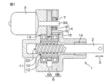
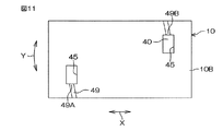
図1は、本発明の第1実施形態に係るボールねじ装置11が適用された電動アクチュエータ1の模式的な断面図である。電動アクチュエータ1は、駆動軸2を軸方向Xに出退させることにより駆動対象を駆動する。
Hereinafter, embodiments of the present invention will be described in detail with reference to the accompanying drawings.
<First Embodiment>
FIG. 1 is a schematic cross-sectional view of an electric actuator 1 to which a ball screw device 11 according to a first embodiment of the present invention is applied. The electric actuator 1 drives the drive target by moving the drive shaft 2 back and forth in the axial direction X.

電動アクチュエータ1は、電動モータ3と、駆動軸2と、電動モータ3の回転トルクを伝達する減速機構4と、減速機構4を介して伝達された電動モータ3の回転トルクを、駆動軸2の軸方向Xの直線運動に変換するボールねじ装置11と、駆動軸2、減速機構4およびボールねじ装置11を収容するハウジング6とを備えている。
ハウジング6は、第1ハウジング6Aと、その端面に突き合わされた第2ハウジング6Bとを有し、固定ボルト(図示しない)によって互いに結合されている。
The electric actuator 1 includes an electric motor 3, a drive shaft 2, a reduction mechanism 4 that transmits the rotation torque of the electric motor 3, and the rotation torque of the electric motor 3 that is transmitted via the reduction mechanism 4. A ball screw device 11 that converts linear motion in the axial direction X and a housing 6 that houses the drive shaft 2, the speed reduction mechanism 4, and the ball screw device 11 are provided.
The housing 6 includes a first housing 6A and a second housing 6B that is abutted against the end surface thereof, and are coupled to each other by a fixing bolt (not shown).

電動モータ3は、第1ハウジング6Aに取り付けられている。電動モータ3の出力軸3Aは第1ハウジング6Aを挿通し、第2ハウジング6Bに装着された転がり軸受7によって回転可能に支持されている。
駆動軸2は、ボールねじ装置11のねじ軸22と一体に形成されている。駆動軸2は、第2ハウジング6B内において、すべり軸受14を介して回転可能に支持されている。
The electric motor 3 is attached to the first housing 6A. The output shaft 3A of the electric motor 3 passes through the first housing 6A and is rotatably supported by a rolling bearing 7 mounted on the second housing 6B.
The drive shaft 2 is formed integrally with the screw shaft 22 of the ball screw device 11. The drive shaft 2 is rotatably supported via a slide bearing 14 in the second housing 6B.

減速機構4は、第1歯車8と、第2歯車9とを備えている。第1歯車8は、第1および第2ハウジング6A,6Bの間に収容配置されており、電動モータ3の出力軸3Aの端部に相対回転不能に取り付けられている。第2歯車9は、ボールナット10の外周に外嵌され、かつ第1歯車8に噛み合っている。ボールナット10は、第1ハウジング6Aの内周に外嵌装着された転がり軸受13、および第2ハウジング6Bの内周に装着された転がり軸受16によって回転可能に支持されている。第2歯車9、転がり軸受13および転がり軸受16は、ボールナット10の外周に外嵌固定されている。   The speed reduction mechanism 4 includes a first gear 8 and a second gear 9. The first gear 8 is housed and disposed between the first and second housings 6A and 6B, and is attached to the end of the output shaft 3A of the electric motor 3 so as not to be relatively rotatable. The second gear 9 is fitted on the outer periphery of the ball nut 10 and meshed with the first gear 8. The ball nut 10 is rotatably supported by a rolling bearing 13 fitted on the inner periphery of the first housing 6A and a rolling bearing 16 attached on the inner periphery of the second housing 6B. The second gear 9, the rolling bearing 13 and the rolling bearing 16 are externally fitted and fixed to the outer periphery of the ball nut 10.

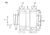
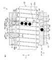
図2は、ボールねじ装置11の模式的な側面図である。図3は、ボールねじ装置11の分解斜視図である。図3では、ボールねじ装置11のうちねじ軸22を省略した構成を示している。図4は、ボールねじ装置11の模式的な縦断面図である。
図2〜図4に示すように、ボールねじ装置11は、軸方向Xに沿って延びるねじ軸22と、ねじ軸22に対して外嵌されたボールナット10と、ねじ軸22とボールナット10との間に介在された複数のボール24と、ボールナット10の外周を包囲する円筒12と、一対のコマ40とを含む。また、換言すると、軸方向Xは、ねじ軸22の軸方向である。ボールねじ装置11は、理論上必要な有効巻数が2.7であり、その理論上の有効巻数をそのまま採用している。
FIG. 2 is a schematic side view of the ball screw device 11. FIG. 3 is an exploded perspective view of the ball screw device 11. In FIG. 3, the structure which abbreviate | omitted the screw shaft 22 among the ball screw apparatuses 11 is shown. FIG. 4 is a schematic longitudinal sectional view of the ball screw device 11.
As shown in FIGS. 2 to 4, the ball screw device 11 includes a screw shaft 22 extending along the axial direction X, a ball nut 10 fitted to the screw shaft 22, and the screw shaft 22 and the ball nut 10. A plurality of balls 24 interposed between the cylinder nut 12, the cylinder 12 surrounding the outer periphery of the ball nut 10, and a pair of pieces 40. In other words, the axial direction X is the axial direction of the screw shaft 22. The ball screw device 11 has a theoretically necessary effective number of turns of 2.7, and adopts the theoretically effective number of turns as it is.

図2および図4に示すように、ねじ軸22の外周面22Aにはねじ溝41が形成されている。ねじ溝41は、ねじ軸22の円中心を中心として旋回しながら軸方向Xの他方(図2および図4の右方)へ徐々にずれる螺旋状の溝である。ねじ溝41の断面は、略U字状の湾曲面である。外周面22Aには、軸方向Xに隣り合うねじ溝41の境界をなす螺旋状のねじ山42が形成されている。   As shown in FIGS. 2 and 4, a screw groove 41 is formed on the outer peripheral surface 22 </ b> A of the screw shaft 22. The screw groove 41 is a spiral groove that gradually turns to the other side in the axial direction X (to the right in FIGS. 2 and 4) while turning around the circle center of the screw shaft 22. The cross section of the thread groove 41 is a substantially U-shaped curved surface. On the outer peripheral surface 22A, a spiral thread 42 that forms a boundary between the thread grooves 41 adjacent to each other in the axial direction X is formed.

図3および図4に示すように、ボールナット10は、鋼などの金属を用いて形成され、軸方向Xに延びる筒状体である。その内周面10Aおよび外周面10Bは、軸方向Xに延びる中心軸を有する円筒面となっている。
ボールナット10の内周面10Aには、ねじ溝43が形成されている。ねじ溝43は、内周面10Aの円中心を中心として旋回しながら軸方向Xの他方(図4の右方)へ徐々にずれる螺旋状の溝である。ねじ溝43の断面は、略U字状の湾曲面である。内周面10Aには、軸方向Xに隣り合うねじ溝43の境界をなす螺旋状のねじ山44が形成されている。
As shown in FIGS. 3 and 4, the ball nut 10 is a cylindrical body that is formed using a metal such as steel and extends in the axial direction X. The inner peripheral surface 10A and the outer peripheral surface 10B are cylindrical surfaces having a central axis extending in the axial direction X.
A thread groove 43 is formed on the inner peripheral surface 10 </ b> A of the ball nut 10. The thread groove 43 is a spiral groove that gradually turns to the other side in the axial direction X (to the right in FIG. 4) while turning around the center of the circle of the inner peripheral surface 10A. The cross section of the thread groove 43 is a substantially U-shaped curved surface. A spiral thread 44 that forms a boundary between adjacent thread grooves 43 in the axial direction X is formed on the inner peripheral surface 10A.

ボールナット10の内周面10Aには、2つの収容穴(収容凹所)45が形成されている。2つの収容穴45は、内周面10Aにおいて、軸方向Xに間隔を空けられた転動開始位置(他方の収用凹所形成位置)47Aおよび転動終了位置(一方の収容凹所形成位置)47Bに配置されている。より具体的には、転動開始位置47Aおよび転動終了位置47Bは、内周面10Aのねじ溝43の内壁に開口している。2つの収容穴45は、平行になった状態で、軸方向Xに間隔を隔てて(この実施形態では、ねじ溝43の3つ分に相当)に間隔を隔てて配置されている。各収容穴45は、内周面10Aの径方向外側へ延びて、ボールナット10の周壁10Cを径方向に貫通している。   Two accommodation holes (accommodation recesses) 45 are formed in the inner peripheral surface 10 </ b> A of the ball nut 10. The two receiving holes 45 have a rolling start position (the other receiving recess forming position) 47A and a rolling end position (one receiving recess forming position) spaced apart in the axial direction X on the inner peripheral surface 10A. 47B. More specifically, the rolling start position 47A and the rolling end position 47B are opened in the inner wall of the screw groove 43 on the inner peripheral surface 10A. The two receiving holes 45 are arranged in parallel with a gap in the axial direction X (corresponding to three screw grooves 43 in this embodiment). Each accommodation hole 45 extends radially outward of the inner peripheral surface 10A and penetrates the peripheral wall 10C of the ball nut 10 in the radial direction.

軸方向Xにおいてボールナット10の内周面10Aが存在する領域において、ボールナット10のねじ溝43と、ねじ軸22の外周面22Aにおいて内周面10Aに対向している部分におけるねじ溝41とによって、ボール転動路47(図4参照)が形成されている。つまり、ボールナット10およびねじ軸22の互いのねじ溝41,43によって螺旋状のボール転動路47が形成されている。ボール転動路47は、略円形状の断面を有しており(図4参照)、ボールナット10やねじ軸22の円中心を中心として旋回しながら軸方向Xの他方(図4の右方)へ徐々にずれる螺旋状をなしている。軸方向Xにおいて隣り合うボール転動路47の間には、ねじ軸22のねじ山42とボールナット10のねじ山44とが径方向に対向した状態で配置されており、これらのねじ山42,44は、軸方向Xにおいて隣り合う2列のボール転動路47の境界をなしている。   In the region where the inner peripheral surface 10A of the ball nut 10 exists in the axial direction X, the screw groove 43 of the ball nut 10 and the screw groove 41 in the portion of the outer peripheral surface 22A of the screw shaft 22 facing the inner peripheral surface 10A Thus, a ball rolling path 47 (see FIG. 4) is formed. That is, a spiral ball rolling path 47 is formed by the thread grooves 41 and 43 of the ball nut 10 and the screw shaft 22. The ball rolling path 47 has a substantially circular cross section (see FIG. 4), and the other of the axial direction X (rightward in FIG. 4) while turning around the circle center of the ball nut 10 or the screw shaft 22. ) To form a spiral. Between the ball rolling paths 47 adjacent to each other in the axial direction X, the thread 42 of the screw shaft 22 and the thread 44 of the ball nut 10 are arranged in a state of being opposed to each other in the radial direction. , 44 form a boundary between two rows of ball rolling paths 47 adjacent in the axial direction X.

図4に示すように、各収容穴45は、ボールナット10の外周面10B側の外領域45Aと、外領域45Aよりも内周面10A側の内領域45Bとを含んでいる。ボールナット10の外側(径方向外側)から見て、各収容穴45(外領域45Aおよび内領域45Bの両方)は、ねじ溝43の傾斜角に相当する角度だけ周方向Yに対して傾斜する方向に沿って長い。   As shown in FIG. 4, each accommodation hole 45 includes an outer region 45A on the outer peripheral surface 10B side of the ball nut 10 and an inner region 45B on the inner peripheral surface 10A side with respect to the outer region 45A. When viewed from the outside (radially outward) of the ball nut 10, each accommodation hole 45 (both the outer region 45 </ b> A and the inner region 45 </ b> B) is inclined with respect to the circumferential direction Y by an angle corresponding to the inclination angle of the screw groove 43. Long along the direction.

ボールナット10において各収容穴45を区画する部分には、外領域45Aと内領域45Bとの境界をなす段差部分46が形成されている。
図3および図4に示すように、ボールナット10の外周面10Bには、外周旋回溝49が形成されている。外周旋回溝49は、外周面10Bの円中心(すなわち、内周面10Aの円中心)を中心として旋回し、軸方向Xの一方(図4の左方)へずれる螺旋状の溝である。換言すると、外周旋回溝49は、外周面10Bに沿って螺旋状に旋回している。
A step portion 46 that forms a boundary between the outer region 45 </ b> A and the inner region 45 </ b> B is formed in a portion of the ball nut 10 that divides each accommodation hole 45.
As shown in FIGS. 3 and 4, an outer peripheral turning groove 49 is formed on the outer peripheral surface 10 </ b> B of the ball nut 10. The outer peripheral turning groove 49 is a spiral groove that turns about the circle center of the outer peripheral surface 10B (that is, the circle center of the inner peripheral surface 10A) and shifts to one of the axial directions X (leftward in FIG. 4). In other words, the outer peripheral turning groove 49 is spirally turned along the outer peripheral surface 10B.

この実施形態では、外周旋回溝49として一巻きの外周旋回溝を例示している。外周旋回溝49の断面は略U字状(略半円状)またはコ字状をなしており(図4ではU字状)、外周旋回溝49は、ボール24(図4では黒丸で示す)の全部分を収容できる溝深さD(図4参照)を有し、エンドミル等を用いて切削形成される。外周旋回溝49の一端49A(図3参照)は、転動開始位置47A側(図3の左手前側)の収容穴45を区画している周壁10Cに接続されており、外周旋回溝49の他端49Bは、転動終了位置47B側(図3の右奥側)の収容穴45を区画している周壁10Cに接続されている。   In this embodiment, the outer peripheral turning groove 49 is illustrated as a single outer peripheral turning groove. The cross section of the outer peripheral turning groove 49 is substantially U-shaped (substantially semicircular) or U-shaped (U shape in FIG. 4), and the outer peripheral turning groove 49 is a ball 24 (indicated by a black circle in FIG. 4). And has a groove depth D (see FIG. 4) that can accommodate all of the above portions, and is formed by cutting using an end mill or the like. One end 49 </ b> A (see FIG. 3) of the outer peripheral turning groove 49 is connected to the peripheral wall 10 </ b> C that defines the accommodation hole 45 on the rolling start position 47 </ b> A side (the left front side in FIG. 3). The end 49B is connected to the peripheral wall 10C that defines the accommodation hole 45 on the rolling end position 47B side (right rear side in FIG. 3).

外周旋回溝49と円筒12の内周面12Aとによって、旋回転動路60が形成される。旋回転動路60は、ボールナット10やねじ軸22の円中心を中心として旋回しながら、軸方向Xの一方(図4の左方)へ徐々にずれる螺旋状をなしている。なお、旋回転動路60によって導かれる軸方向は、ボール転動路47によって導かれる軸方向とは逆向きの軸方向である。   A turning rotation path 60 is formed by the outer peripheral turning groove 49 and the inner peripheral surface 12A of the cylinder 12. The rotational path 60 has a spiral shape that gradually shifts to one of the axial directions X (leftward in FIG. 4) while turning around the circle center of the ball nut 10 or the screw shaft 22. Note that the axial direction guided by the rotation path 60 is opposite to the axial direction guided by the ball rolling path 47.

図4に示すように、ボール24は、金属等で形成された小さな球体であって、ボール転動路47内に配置されており、ボール転動路47内で自由に転動できる。なお、説明の便宜上、図4では、ボール転動路47内に配置される全てのボール24のうちの一部のみ(黒丸部分参照)を図示している(後述する図6、図7、図9、図14、図17、図18、図22〜図25でも同様)。   As shown in FIG. 4, the ball 24 is a small sphere formed of metal or the like and is disposed in the ball rolling path 47 and can freely roll in the ball rolling path 47. For convenience of explanation, FIG. 4 shows only a part of all the balls 24 arranged in the ball rolling path 47 (see the black circles) (FIGS. 6, 7, and 7 to be described later). 9, FIG. 14, FIG. 17, FIG. 18, FIG. 22 to FIG.

図3および図4に示すように、円筒12は鋼などの金属を用いて形成されており、その内周面12Aおよび外周面12Bは、それぞれ、ボールナット10の内外周面10A,10Bと同軸を有する円筒面となっている。円筒12の内周面12Aおよび外周面12Bには溝が形成されておらず、換言すると、内周面12Aおよび外周面12Bは、次に述べる係合穴48が形成される位置を除いて、それぞれ円筒面のみから形成されている。円筒12は、ボールナット10の外周面10B全域をすっぽり包囲した状態で、ボールナット10に同伴回転可能かつ軸方向Xに同伴移動可能に取り付けられている。円筒12の内径はボールナット10の外径よりも若干大きく設定されており、そのため、ボールナット10に対する円筒12の取付状態では、円筒12の内周面12Aが、ボールナット10の外周面10Bとの間に微小間隔Sを隔てて設けられている。   As shown in FIGS. 3 and 4, the cylinder 12 is formed using a metal such as steel, and the inner peripheral surface 12 </ b> A and the outer peripheral surface 12 </ b> B are coaxial with the inner and outer peripheral surfaces 10 </ b> A and 10 </ b> B of the ball nut 10, respectively. It becomes the cylindrical surface which has. Grooves are not formed on the inner peripheral surface 12A and the outer peripheral surface 12B of the cylinder 12, in other words, the inner peripheral surface 12A and the outer peripheral surface 12B are formed except for the position where the engagement hole 48 described below is formed. Each is formed only from a cylindrical surface. The cylinder 12 is attached to the ball nut 10 so as to be able to rotate along with the ball nut 10 and move in the axial direction X in a state where the entire outer peripheral surface 10B of the ball nut 10 is completely surrounded. The inner diameter of the cylinder 12 is set to be slightly larger than the outer diameter of the ball nut 10. Therefore, when the cylinder 12 is attached to the ball nut 10, the inner peripheral surface 12 A of the cylinder 12 is different from the outer peripheral surface 10 B of the ball nut 10. Are provided with a small interval S therebetween.

図3および図4に示すように、円筒12の内周面12Aには、円筒12を厚み方向に貫通する2つの係合穴(係合凹所)48が形成されている。係合穴48は、収容穴45と同数(この実施形態では2つ)設けられている。2つの係合穴48は、平行になった状態で、軸方向Xに間隔を隔てて(この実施形態では、ねじ溝43の3つ分に相当)配置されている。円筒12がボールナット10に同伴回転可能に設けられる状態において、2つの係合穴48の径方向外方から見た形状が、それぞれ収容穴45の外領域45A(図4参照)に整合している。   As shown in FIGS. 3 and 4, two engagement holes (engagement recesses) 48 penetrating the cylinder 12 in the thickness direction are formed on the inner peripheral surface 12 </ b> A of the cylinder 12. The same number of engagement holes 48 as the accommodation holes 45 (two in this embodiment) are provided. The two engagement holes 48 are arranged in parallel with an interval in the axial direction X (corresponding to three screw grooves 43 in this embodiment). In a state in which the cylinder 12 is rotatably provided along with the ball nut 10, the shapes of the two engagement holes 48 viewed from the radially outer side are aligned with the outer region 45 </ b> A (see FIG. 4) of the accommodation hole 45. Yes.

コマ40は、小片状をなし、収容穴45と同数(この実施形態では2つ)設けられており、各収容穴45に1つずつ装着される。各コマ40は、収容穴45および係合穴48の双方を挿通している。コマ40の材質としては、樹脂や金属などを採用できる。
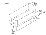
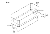
図5Aは、コマ40の斜視図である。図5Bは、図5Aを右奥側から見た斜視図である。図5Aおよび図5Bに示すように、コマ40は、外部分51と内部分52とを一体的に含んでいる。
The tops 40 are in the form of small pieces and are provided in the same number as the accommodation holes 45 (two in this embodiment), and one piece is installed in each accommodation hole 45. Each piece 40 passes through both the accommodation hole 45 and the engagement hole 48. As the material of the top 40, resin, metal, or the like can be used.
FIG. 5A is a perspective view of the top 40. FIG. 5B is a perspective view of FIG. 5A viewed from the right rear side. As shown in FIGS. 5A and 5B, the top 40 includes an outer portion 51 and an inner portion 52 integrally.

外部分51は、ブロック状をなしている。外部分51は、円筒12をボールナット10に取り付けた状態における、収容穴45の外領域45A(図4参照)および係合穴48を足し合わせた領域にちょうど嵌る形状を有しており、たとえば、四隅の端縁が面取りされた直方体状である。なお、外部分51において図5Aおよび図5Bで大きく表れている表面を外面51Aと呼ぶことにすると、図5Aおよび図5Bでは外面51Aを平坦面状に描いているが、外面51Aが、円筒12の外周面12Bに面一になるように湾曲している。   The external portion 51 has a block shape. The outer portion 51 has a shape that fits just into the outer region 45A (see FIG. 4) of the accommodation hole 45 and the region where the engagement hole 48 is added in a state where the cylinder 12 is attached to the ball nut 10, for example, A rectangular parallelepiped shape with four corner edges chamfered. 5A and 5B, the outer surface 51A is depicted as a flat surface in FIGS. 5A and 5B. However, the outer surface 51A is a cylinder 12. Is curved so as to be flush with the outer peripheral surface 12B.

内部分52は、外部分51の長手方向に沿って長手のブロック状である。内部分52は、収容穴45の内領域45B(図4参照)にちょうど嵌る形状を有しており、内部分52では、長手方向における両端部が丸められている。外部分51において、外面51Aとは反対側の面を内面51Bと呼ぶことにすると、内部分52は、内面51Bに固定されている。外部分51の厚み方向から見て、内部分52は、外部分51の輪郭の内側に位置している。   The inner part 52 has a longitudinal block shape along the longitudinal direction of the outer part 51. The inner portion 52 has a shape that just fits in the inner region 45B (see FIG. 4) of the accommodation hole 45, and both end portions in the longitudinal direction of the inner portion 52 are rounded. In the outer portion 51, when the surface opposite to the outer surface 51A is called an inner surface 51B, the inner portion 52 is fixed to the inner surface 51B. The inner portion 52 is located inside the contour of the outer portion 51 when viewed from the thickness direction of the outer portion 51.

各コマ40は、接続路54を有している。接続路54は、コマ40の内部をトンネル状に延び、コマ40の長手方向の一端面(図5Aの左手前側端面)に開口する円形の外側開口55と、コマ40の長手方向の他端面(図5Aの右奥側端面)に開口する円形の内側開口56とを連通し、断面円形をなしている。
外側開口55と内側開口56とは、径方向位置(円中心からの距離)が互いに異ならされており、外側開口55が内側開口56よりも径方向外側に配置されている。そのため、接続路54は、内側開口56から外側開口55に向かうに従って径方向外側に向かう傾斜状をなしている。
Each frame 40 has a connection path 54. The connection path 54 extends inside the frame 40 in a tunnel shape, and has a circular outer opening 55 that opens on one end surface in the longitudinal direction of the frame 40 (the left front side end surface in FIG. 5A) and the other end surface in the longitudinal direction of the frame 40 ( It communicates with a circular inner opening 56 that opens to the right back side end face of FIG.
The outer opening 55 and the inner opening 56 are different from each other in radial position (distance from the center of the circle), and the outer opening 55 is disposed radially outside the inner opening 56. Therefore, the connection path 54 has an inclined shape that extends radially outward from the inner opening 56 toward the outer opening 55.

図4に示すように、各コマ40は、ボールナット10の収容穴45および円筒12の係合穴48に対して、ボールナット10側から、より詳しくはボールナット10の径方向外側から装着(挿入)される。収容穴45および係合穴48の双方にコマ40が装着された状態では、外部分51が収容穴45の外領域45Aおよび係合穴48に収容され、内部分52が、収容穴45の内領域45Bに収容される。このとき、外部分51の内面51Bの周縁部が、収容穴45における段差部分46に対してボールナット10の径方向外側から当接しており、これによって、コマ40が収容穴45内で位置決めされる。また、長方体状の外部分51における四隅が外面51A側からかしめられることによって、各コマ40は、ボールナット10および円筒12の双方に固定される。各収容穴45に装着されているコマ40が係合穴48の周囲の周壁に係合すること(係合穴48への嵌合)により、円筒12のボールナット10に対する相対回転および相対軸方向X移動が阻止される。換言すると、第1実施形態では、特許請求の範囲の「相対回転阻止構造」は、係合穴48とコマ40とを有し、収容穴45に収容されているコマ40の一部が係合穴48に嵌合(係合)する構造である。   As shown in FIG. 4, each piece 40 is attached to the accommodation hole 45 of the ball nut 10 and the engagement hole 48 of the cylinder 12 from the ball nut 10 side, more specifically, from the radially outer side of the ball nut 10 ( Inserted). In a state in which the top 40 is mounted in both the receiving hole 45 and the engaging hole 48, the outer portion 51 is received in the outer region 45 </ b> A of the receiving hole 45 and the engaging hole 48, and the inner portion 52 is set in the receiving hole 45. Housed in region 45B. At this time, the peripheral edge portion of the inner surface 51B of the outer portion 51 is in contact with the stepped portion 46 in the accommodation hole 45 from the outside in the radial direction of the ball nut 10, whereby the top 40 is positioned in the accommodation hole 45. The Further, the four corners of the rectangular outer portion 51 are caulked from the outer surface 51 </ b> A side, whereby each piece 40 is fixed to both the ball nut 10 and the cylinder 12. Relative rotation and relative axial direction of the cylinder 12 with respect to the ball nut 10 by engaging the tops 40 mounted in the respective receiving holes 45 with the peripheral walls around the engaging holes 48 (fitting to the engaging holes 48). X movement is blocked. In other words, in the first embodiment, the “relative rotation blocking structure” in the claims has the engagement hole 48 and the top 40, and a part of the top 40 accommodated in the accommodation hole 45 is engaged. The structure is fitted (engaged) with the hole 48.

図6は、コマ40の装着状態においてボールナット10を径方向外方から見た図である。
転動開始位置47A側(図3の左手前側)の収容穴45に装着されるコマ40と、転動終了位置47B側(図3の右奥側)の収容穴45に装着されるコマ40とは、周方向Yに関し互いに逆向きになるように装着される。転動開始位置47A側(図3の左手前側)の収容穴45には、コマ40の外側開口55が外周旋回溝49の一端49Aに対向するようにコマ40が装着され、転動終了位置47B側(図3の右奥側)の収容穴45には、コマ40の外側開口55が外周旋回溝49の他端49Bに対向するようにコマ40が装着される。
FIG. 6 is a view of the ball nut 10 as viewed from the outside in the radial direction when the top 40 is mounted.
The top 40 mounted in the accommodation hole 45 on the rolling start position 47A side (left front side in FIG. 3), and the top 40 installed in the accommodation hole 45 on the rolling end position 47B side (right rear side in FIG. 3). Are mounted so as to be opposite to each other in the circumferential direction Y. The top 40 is mounted in the accommodation hole 45 on the rolling start position 47A side (the left front side in FIG. 3) so that the outer opening 55 of the top 40 faces one end 49A of the outer circumferential turning groove 49, and the rolling end position 47B. The top 40 is mounted in the accommodation hole 45 on the side (the right back side in FIG. 3) so that the outer opening 55 of the top 40 faces the other end 49 </ b> B of the outer periphery turning groove 49.

ボールナット10および円筒12へのコマ40の装着状態において、コマ40の接続路54の外側開口55は、軸方向Xで同じ位置にある外周旋回溝49(旋回転動路60)に連通(合流)している。また、この状態において、コマ40の接続路54の内側開口56は、軸方向Xで同じ位置にあるボール転動路47に連通している。
これにより、2つのコマ40の接続路54と、外周旋回溝49と円筒12の内周面12Aとによって形成される旋回転動路60とが、軸方向Xにおけるボール転動路47のバイパスとなっている。換言すると、旋回転動路60および2つの接続路54によって、ボール転動路47内の転動終了位置47Bのボール24をボール転動路47内の転動開始位置47Aに戻すための循環路61が形成される。
In the state in which the top 40 is mounted on the ball nut 10 and the cylinder 12, the outer opening 55 of the connection path 54 of the top 40 communicates (joins) with the outer peripheral turning groove 49 (the turning path 60) located at the same position in the axial direction X. )doing. Further, in this state, the inner opening 56 of the connection path 54 of the top 40 communicates with the ball rolling path 47 located at the same position in the axial direction X.
As a result, the connection path 54 of the two tops 40 and the rotational rotation path 60 formed by the outer peripheral turning groove 49 and the inner peripheral surface 12A of the cylinder 12 are bypassed from the ball rolling path 47 in the axial direction X. It has become. In other words, the circulation path for returning the ball 24 at the rolling end position 47B in the ball rolling path 47 to the rolling start position 47A in the ball rolling path 47 by the turning path 60 and the two connection paths 54. 61 is formed.

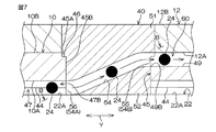
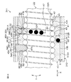
図7は、図6の切断面線A−Aから見た断面図である。図8は、図7の切断面線B−Bから見た断面図である。なお、図7では、便宜上、周方向Yが直線方向になるように描いている。したがって、ねじ軸22の外周面22A、およびボールナット10の内外周面10A,10Bは図7においてそれぞれ直線状に示されているが、実際は円弧状をなしている(後述する図9、図17、図18、図24、図25において同様)。   FIG. 7 is a cross-sectional view taken along the section line AA of FIG. FIG. 8 is a cross-sectional view taken along the section line BB in FIG. In FIG. 7, for the sake of convenience, the circumferential direction Y is drawn in a straight line direction. Accordingly, the outer peripheral surface 22A of the screw shaft 22 and the inner and outer peripheral surfaces 10A and 10B of the ball nut 10 are each shown in a straight line shape in FIG. 7, but actually have an arc shape (FIGS. 9 and 17 described later). The same applies to FIGS. 18, 24, and 25).

図6〜図8に示すように、転動終了位置47B側(図3の右奥側)の収容穴45に装着されるコマ40は、ボールナット10の内周側のボール転動路47から、外周側の旋回転動路60へとボール24を導くために用いられる。このとき、接続路54の内側開口56が入口54Aとして機能し、かつ接続路54の外側開口55が出口54Bとして機能する。   As shown in FIGS. 6 to 8, the top 40 mounted in the accommodation hole 45 on the rolling end position 47 </ b> B side (the right rear side in FIG. 3) is separated from the ball rolling path 47 on the inner peripheral side of the ball nut 10. It is used to guide the ball 24 to the rotation path 60 on the outer peripheral side. At this time, the inner opening 56 of the connection path 54 functions as the inlet 54A, and the outer opening 55 of the connection path 54 functions as the outlet 54B.

図7に示すように、接続路54の外側開口55および内側開口56を除く部分では、接続路54に沿いかつ周方向Yに直交する方向の断面形状が直線状をなしている。接続路54において外側開口55付近および内側開口56付近の部分は、接続路54に沿いかつ周方向Yに直交する方向の断面形状が、接続路54の他の部分よりも勾配を緩やかにした湾曲状である。   As shown in FIG. 7, in a portion of the connection path 54 excluding the outer opening 55 and the inner opening 56, the cross-sectional shape along the connection path 54 and perpendicular to the circumferential direction Y is linear. In the connection path 54, the portions near the outer opening 55 and the inner opening 56 are curved such that the cross-sectional shape along the connection path 54 and perpendicular to the circumferential direction Y has a gentler slope than the other parts of the connection path 54. Is.

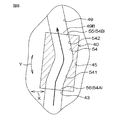
図8に示すように、接続路54は、周方向Yに沿う方向に関し、「く」の字状に屈曲している。具体的には、ねじ溝43とやや傾斜しつつ略直線状に延びる第1部分541と、外周旋回溝49に沿って略直線状に延びる第2部分542とを備えている。このような接続路54により、互いに向きの異なるねじ溝43と外周旋回溝49とを連通させることができる。   As shown in FIG. 8, the connection path 54 is bent in a “<” shape with respect to the direction along the circumferential direction Y. Specifically, the screw groove 43 is provided with a first portion 541 that extends substantially linearly while being slightly inclined, and a second portion 542 that extends substantially linearly along the outer peripheral turning groove 49. Such a connection path 54 allows the screw groove 43 and the outer peripheral turning groove 49 having different directions to communicate with each other.

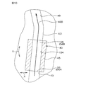
図9は、図6の切断面線C−Cから見た断面図である。
図6および図9に示すように、転動開始位置47A側(図3の左手前側)の収容穴45に装着されるコマ40は、ボールナット10の外周側の旋回転動路60から、内周側のボール転動路47へとボール24を導くために用いられる。このとき、接続路54の外側開口55が入口54Aとして機能し、かつ接続路54の内側開口56が出口54Bとして機能する。なお、転動開始位置47A側(図3の左手前側)の収容穴45に装着されるコマ40は、転動終了位置47B側(図3の右奥側)の収容穴45に装着されるコマ40と同じ諸元を有している。
FIG. 9 is a cross-sectional view taken along the section line CC of FIG.
As shown in FIGS. 6 and 9, the top 40 mounted in the accommodation hole 45 on the rolling start position 47 </ b> A side (the left front side in FIG. 3) is connected to the inner side of the rotational rotation path 60 on the outer peripheral side of the ball nut 10. It is used to guide the ball 24 to the ball rolling path 47 on the circumferential side. At this time, the outer opening 55 of the connection path 54 functions as the inlet 54A, and the inner opening 56 of the connection path 54 functions as the outlet 54B. Note that the top 40 mounted in the accommodation hole 45 on the rolling start position 47A side (left front side in FIG. 3) is the top mounted in the accommodation hole 45 on the rolling end position 47B side (right rear side in FIG. 3). It has the same specifications as 40.

図6〜図9に示すように、ボール転動路47内のボール24は、ボールナット10の回転に伴ってボール転動路47内で転動しながらボール転動路47に沿って、転動開始位置47Aから転動終了位置47Bまで移動する。ボール24は、転動終了位置47Bに到達すると、転動終了位置47B側(図3の右奥側)の収容穴45に装着されるコマ40における接続路54の内側開口56から接続路54内に進入し、この接続路54を通って、ボールナット10の外周面10Bの外周旋回溝49に掬い上げられる(図6に示す矢印参照)。   As shown in FIGS. 6 to 9, the ball 24 in the ball rolling path 47 rolls along the ball rolling path 47 while rolling in the ball rolling path 47 as the ball nut 10 rotates. It moves from the movement start position 47A to the rolling end position 47B. When the ball 24 reaches the rolling end position 47B, the ball 24 enters the inside of the connection path 54 from the inner opening 56 of the connection path 54 in the top 40 mounted in the accommodation hole 45 on the rolling end position 47B side (the right rear side in FIG. 3). , And passes through the connection path 54 to be scooped up into the outer peripheral turning groove 49 of the outer peripheral surface 10B of the ball nut 10 (see the arrow shown in FIG. 6).

その後、ボール24は、外周旋回溝49を含む旋回転動路60を移動してボールナット10の外周を旋回することで、軸方向Xにおいて今までとは逆向き(図6の左側)へ進む。そして、旋回転動路60を通ったボール24は、転動開始位置47A側(図3の左手前側)の収容穴45に装着されるコマ40の接続路54の外側開口55(入口54A)から接続路54内に進入し、この接続路54を通って、ボール転動路47内の転動開始位置47Aに戻される(図6に示す破線矢印参照)。つまり、ボール転動路47内を移動するボール24が、旋回転動路60および接続路54を含む循環路61によって循環され、これにより、ボール転動路47内におけるボール24の安定供給が可能になる。   Thereafter, the ball 24 moves in the rotational path 60 including the outer periphery turning groove 49 and turns around the outer periphery of the ball nut 10, thereby proceeding in the opposite direction in the axial direction X (the left side in FIG. 6). . Then, the ball 24 that has passed through the rotation path 60 is from the outer opening 55 (inlet 54A) of the connection path 54 of the top 40 that is mounted in the accommodation hole 45 on the rolling start position 47A side (the left front side in FIG. 3). The vehicle enters the connection path 54, passes through the connection path 54, and returns to the rolling start position 47A in the ball rolling path 47 (see the broken line arrow shown in FIG. 6). That is, the ball 24 moving in the ball rolling path 47 is circulated by the circulation path 61 including the rotation path 60 and the connection path 54, thereby enabling stable supply of the balls 24 in the ball rolling path 47. become.

以上によりこの実施形態によれば、ボール24はボール転動路47内を、転動開始位置47Aから転動終了位置47Bまで移動し、転動終了位置47Bから一方のコマ40の接続路54を通って、ボールナット10の外周面10Bの外周旋回溝49に掬い上げられる。外周旋回溝49に掬い上げられたボール24は、外周旋回溝49によって形成される旋回転動路60を通ってボールナット10の外周を旋回した後、他方のコマ40の接続路54を通って、ボール転動路47内の転動開始位置47Aに戻される。すなわち、ボール転動路47内における転動終了位置47Bのボール24が、旋回転動路60を含む循環路61によって、ボール転動路47内における転動開始位置47Aに戻される。これにより、ボール24を、ボール転動路47内でスムーズに循環させることができる。   As described above, according to this embodiment, the ball 24 moves in the ball rolling path 47 from the rolling start position 47A to the rolling end position 47B, and from the rolling end position 47B through the connection path 54 of one piece 40. It passes through the outer peripheral turning groove 49 of the outer peripheral surface 10 </ b> B of the ball nut 10. The ball 24 scooped up in the outer periphery turning groove 49 turns on the outer periphery of the ball nut 10 through the turning rotation path 60 formed by the outer periphery turning groove 49, and then passes through the connection path 54 of the other piece 40. Returning to the rolling start position 47A in the ball rolling path 47. That is, the ball 24 at the rolling end position 47B in the ball rolling path 47 is returned to the rolling start position 47A in the ball rolling path 47 by the circulation path 61 including the rotation path 60. Thereby, the ball 24 can be smoothly circulated in the ball rolling path 47.

また、ボールナット10の外周面10Bの外周旋回溝49と円筒12の内周面12Aとによって、循環路61に含まれる旋回転動路60が形成される。そのため、転動開始位置47Aおよび転動終了位置47Bが軸方向Xおよび周方向Yに如何なる相対関係を有していても、転動開始位置47Aと転動終了位置47Bとを循環路61でつなぐことが可能である。そのため、コマ40の相対的な配置位置に、軸方向Xに沿って延びる貫通孔をボールナット10の周壁10Cを形成する場合のような周方向Yの制約がない。これにより、コマ40の配置位置のレイアウトの自由度を高めることができる。そして、コマ40の配置位置に周方向Yの制約がなくなる結果、ボールねじ装置11の理論上の有効巻数をそのまま採用でき、ゆえに、ボールねじ装置11を軸方向Xに小型化することが可能になる。   In addition, the rotational rotation path 60 included in the circulation path 61 is formed by the outer peripheral turning groove 49 of the outer peripheral surface 10B of the ball nut 10 and the inner peripheral surface 12A of the cylinder 12. Therefore, regardless of the relative relationship between the rolling start position 47A and the rolling end position 47B in the axial direction X and the circumferential direction Y, the rolling start position 47A and the rolling end position 47B are connected by the circulation path 61. It is possible. Therefore, there is no restriction in the circumferential direction Y as in the case where the circumferential wall 10C of the ball nut 10 is formed with a through hole extending along the axial direction X at the relative arrangement position of the top 40. Thereby, the freedom degree of the layout of the arrangement position of the top 40 can be increased. As a result of the absence of the restriction in the circumferential direction Y at the arrangement position of the top 40, the theoretical effective number of turns of the ball screw device 11 can be adopted as it is, and therefore the ball screw device 11 can be miniaturized in the axial direction X. Become.

また、収容穴45に装着されているコマ40が係合穴48の周囲の周壁に係合することにより、円筒12のボールナット10に対する相対回転および相対軸方向X移動が阻止される。すなわち、ボールナット10および円筒12が互いに、軸方向Xおよび周方向Yの双方に関して位置決めされる。これにより、他の部材を用いることなく、相対回転阻止構造を設けることができ、これにより、円筒12のボールナット10に対する相対回転および相対軸方向X移動を阻止しつつ、部品点数が増加するのを防止できる。   Further, when the top 40 mounted in the accommodation hole 45 is engaged with the peripheral wall around the engagement hole 48, relative rotation and relative axial direction X movement of the cylinder 12 with respect to the ball nut 10 are prevented. That is, the ball nut 10 and the cylinder 12 are positioned with respect to each other in both the axial direction X and the circumferential direction Y. Thereby, a relative rotation prevention structure can be provided without using other members, and this increases the number of components while preventing relative rotation and relative axial X movement of the cylinder 12 with respect to the ball nut 10. Can be prevented.

以上、この発明の第1実施形態について説明したが、前述の態様に限られない。たとえば、コマ40の有する接続路54の態様を変更することもできる。
図10は、第1実施形態の第1変形例に係る外周旋回溝49とねじ溝43との接続を説明するための図である。
図10に示すように、接続路154は、周方向Yに関し、ねじ溝43に沿って直線状に延びている。接続路154は、接続路154に沿いかつ周方向Yに直交する方向の断面形状が、接続路54(図8等参照)の場合と同様である。
The first embodiment of the present invention has been described above, but is not limited to the above-described aspect. For example, the aspect of the connection path 54 of the top 40 can be changed.
FIG. 10 is a view for explaining the connection between the outer peripheral turning groove 49 and the screw groove 43 according to a first modification of the first embodiment.
As shown in FIG. 10, the connection path 154 extends linearly along the thread groove 43 in the circumferential direction Y. The connection path 154 has the same cross-sectional shape along the connection path 154 and perpendicular to the circumferential direction Y as in the case of the connection path 54 (see FIG. 8 and the like).

この場合、螺旋状の外周旋回溝49と接続路154とをつなぐ接続溝101が、ボールナット10の外周面10Bに形成される。接続溝101は、接続路154に沿って略直線状に延び、外周旋回溝49の他端49Bにつながっている。
また、前述の第1実施形態では、コマ40が周方向Yに関し揃って配置されるとしたが、図11に示すように、コマ40を周方向Yにずらして配置することが可能である。
In this case, the connection groove 101 that connects the spiral outer periphery turning groove 49 and the connection path 154 is formed on the outer peripheral surface 10 </ b> B of the ball nut 10. The connection groove 101 extends substantially linearly along the connection path 154 and is connected to the other end 49 </ b> B of the outer peripheral turning groove 49.
In the first embodiment described above, the frames 40 are arranged in the circumferential direction Y. However, as shown in FIG. 11, the frames 40 can be arranged shifted in the circumferential direction Y.

図11は、第1実施形態の第2変形例に係る収容穴45およびコマ40の配置を説明するための図である。この場合、一対の収容穴45は周方向Yにずれている。この場合、理論上必要な有効巻数がたとえば2.3であり、その理論上の有効巻数(2.3)をボールねじ装置11にそのまま採用している。これにより、コマ40の配置位置のレイアウトの自由度を高めることができ、ゆえに、ボールねじ装置11を、より一層、軸方向Xに小型化することができる。   FIG. 11 is a diagram for explaining the arrangement of the accommodation holes 45 and the tops 40 according to the second modification of the first embodiment. In this case, the pair of accommodation holes 45 are shifted in the circumferential direction Y. In this case, the theoretically necessary effective number of turns is 2.3, for example, and the theoretically effective number of turns (2.3) is adopted as it is in the ball screw device 11. Thereby, the freedom degree of the layout of the arrangement position of the top 40 can be increased, and therefore the ball screw device 11 can be further downsized in the axial direction X.

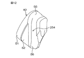
また、図12は、第1実施形態の第3変形例に係るコマ40の構成を示す要部断面図である。第3変形例においては、図12に示すように、接続路54,154に代えて用いられる接続路254が溝状をなしていてもよい。接続路254は、コマ40の長手方向に沿う、コマ40の側壁を突き破るように形成されている。
<第2実施形態>
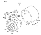
図13は、本発明の第2実施形態に係るボールねじ装置311の分解斜視図である。図14は、ボールねじ装置311の模式的な縦断面図である。図13では、ボールねじ装置311からねじ軸22を省略した構成を示している。ボールねじ装置311は、たとえば、図1を用いて説明した電動アクチュエータ1と同等の電動アクチュエータに適用される。
FIG. 12 is a cross-sectional view of the main part showing the configuration of the top 40 according to a third modification of the first embodiment. In the third modified example, as shown in FIG. 12, the connection path 254 used instead of the connection paths 54 and 154 may have a groove shape. The connection path 254 is formed so as to break through the side wall of the top 40 along the longitudinal direction of the top 40.
Second Embodiment
FIG. 13 is an exploded perspective view of a ball screw device 311 according to the second embodiment of the present invention. FIG. 14 is a schematic longitudinal sectional view of the ball screw device 311. FIG. 13 shows a configuration in which the screw shaft 22 is omitted from the ball screw device 311. The ball screw device 311 is applied to, for example, an electric actuator equivalent to the electric actuator 1 described with reference to FIG.

第2実施形態において、第1実施形態に示された各部に対応する部分には、図1〜図9の場合と同一の参照符号を付して示し、説明を省略する。
図13および図14に示すように、ボールねじ装置311は、ねじ軸22と、ねじ軸22に対して外嵌されたボールナット10と、ねじ軸22とボールナット10との間に介在された複数のボール24と、ボールナット10の外周を包囲する円筒312と、一対のコマ340とを含む。ボールねじ装置311は、円筒として円筒312を採用しかつコマとしてコマ340を採用する点において、本発明の第1実施形態に係るボールねじ装置11と相違している。ボールねじ装置311は、理論上必要な有効巻数が2.7であり、その理論上の有効巻数をそのまま採用している。
In the second embodiment, portions corresponding to the respective portions shown in the first embodiment are denoted by the same reference numerals as those in FIGS. 1 to 9, and description thereof is omitted.
As shown in FIGS. 13 and 14, the ball screw device 311 is interposed between the screw shaft 22, the ball nut 10 externally fitted to the screw shaft 22, and the screw shaft 22 and the ball nut 10. A plurality of balls 24, a cylinder 312 surrounding the outer periphery of the ball nut 10, and a pair of pieces 340 are included. The ball screw device 311 is different from the ball screw device 11 according to the first embodiment of the present invention in that a cylinder 312 is employed as a cylinder and a top 340 is employed as a top. The ball screw device 311 has a theoretically required effective number of turns of 2.7, and adopts the theoretically effective number of turns as it is.

ボールナット10は、第1実施形態に係るボールナット10とほぼ同等の構成である。すなわち、ボールナット10は鋼などの金属を用いて形成され、軸方向Xに延びる筒状体であり、その内周面10Aおよび外周面10Bは、軸方向Xに延びる中心軸を有する円筒面となっている。ボールナット10の内周面10Aには、転動開始位置47Aおよび転動終了位置47Bに、ボールナット10の周壁10Cを厚み方向に貫通する2つの収容穴45が形成されている。   The ball nut 10 has substantially the same configuration as the ball nut 10 according to the first embodiment. That is, the ball nut 10 is formed using a metal such as steel and is a cylindrical body extending in the axial direction X. The inner peripheral surface 10A and the outer peripheral surface 10B are a cylindrical surface having a central axis extending in the axial direction X. It has become. Two accommodation holes 45 penetrating the circumferential wall 10C of the ball nut 10 in the thickness direction are formed in the inner circumferential surface 10A of the ball nut 10 at the rolling start position 47A and the rolling end position 47B.

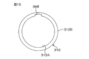
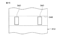
図15は、円筒312の模式的な断面図である。図16は、円筒312の模式的な側面図である。
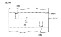
図13〜図16に示すように、円筒312は鋼などの金属を用いて形成されている。円筒312の内周面312Aおよび外周面312Bは、それぞれ、ボールナット10の内外周面10A,10Bと同軸を有する円筒面をなしている。換言すると、外周面312Bは円筒面のみから形成されている。円筒312は、ボールナット10の外周面10B全域をすっぽり包囲した状態で、ボールナット10に同伴回転可能に取り付けられている。円筒312の内径はボールナット10の外径よりも若干大きく設定されており、そのため、ボールナット10に対する円筒312の取付状態では、円筒312の内周面312Aが、ボールナット10の外周面10Bとの間に微小間隔Sを隔てて設けられている。円筒312は、係合凹所として一対の係合穴48に代えて軸方向溝348を設ける点で、本発明の第1実施形態に係る円筒12と異なっている。
FIG. 15 is a schematic cross-sectional view of the cylinder 312. FIG. 16 is a schematic side view of the cylinder 312.
As shown in FIGS. 13 to 16, the cylinder 312 is formed using a metal such as steel. The inner circumferential surface 312A and the outer circumferential surface 312B of the cylinder 312 are cylindrical surfaces that are coaxial with the inner and outer circumferential surfaces 10A and 10B of the ball nut 10, respectively. In other words, the outer peripheral surface 312B is formed only from a cylindrical surface. The cylinder 312 is attached to the ball nut 10 so as to be able to rotate together with the entire outer peripheral surface 10B of the ball nut 10 being completely surrounded. The inner diameter of the cylinder 312 is set to be slightly larger than the outer diameter of the ball nut 10, and therefore, when the cylinder 312 is attached to the ball nut 10, the inner peripheral surface 312 </ b> A of the cylinder 312 is different from the outer peripheral surface 10 </ b> B of the ball nut 10. Are provided with a small interval S therebetween. The cylinder 312 is different from the cylinder 12 according to the first embodiment of the present invention in that an axial groove 348 is provided as an engagement recess instead of the pair of engagement holes 48.

円筒312の内周面312Aには、係合凹所としての軸方向溝348が形成されている。軸方向溝348は、コマ340の外部分351を嵌合可能に設けられている。軸方向溝348は軸方向Xに沿って直線状に、円筒312の軸方向Xの一端(図14に示す左端)から、円筒312の軸方向Xの他端(図14に示す右端)に亘って延びている。軸方向溝348は、図13〜図16に示すように、一定の周方向Yの幅および一定深さに設定されている。円筒312がボールナット10に同伴回転可能に設けられる状態において、径方向外方から見た形状が、2つの収容穴45の外領域45Aに重複している。軸方向溝348の溝幅は、次に述べる各コマ340が嵌った状態においてボールナット10と円筒348とが相対回転しないように、各コマ340の周方向Yに沿う方向の長さと同じ長さに設定されている。   An axial groove 348 as an engagement recess is formed on the inner peripheral surface 312A of the cylinder 312. The axial groove 348 is provided so that the outer portion 351 of the top 340 can be fitted. The axial groove 348 extends linearly along the axial direction X from one end of the cylinder 312 in the axial direction X (left end shown in FIG. 14) to the other end of the cylinder 312 in the axial direction X (right end shown in FIG. 14). It extends. As shown in FIGS. 13 to 16, the axial groove 348 is set to have a constant circumferential width Y and a constant depth. In a state where the cylinder 312 is provided so as to be able to rotate along with the ball nut 10, the shape viewed from the outside in the radial direction overlaps the outer region 45 </ b> A of the two accommodation holes 45. The groove width of the axial groove 348 is the same as the length in the direction along the circumferential direction Y of each piece 340 so that the ball nut 10 and the cylinder 348 do not rotate relative to each other when each piece 340 described below is fitted. Is set to

コマ340は小片状をなし、収容穴45と同数(この実施形態では2つ)設けられており、各収容穴45に1つずつ装着される。各コマ340は、収容穴45に収容されており、その状態でボールナット10の外周面10Bから外方に突出する外部分351が、軸方向溝348に嵌合している。コマ340の材質としては、第1実施形態に係るコマ40と同様、樹脂や金属などを採用することができる。   The tops 340 are in the form of small pieces and are provided in the same number as the accommodation holes 45 (two in this embodiment), and one piece is installed in each accommodation hole 45. Each piece 340 is accommodated in the accommodation hole 45, and an outer portion 351 protruding outward from the outer peripheral surface 10 </ b> B of the ball nut 10 in this state is fitted in the axial groove 348. As the material of the top 340, resin, metal, or the like can be used as in the top 40 according to the first embodiment.

図13に示すように、コマ340は、外部分351と内部分52とを一体的に含んでいる。コマ340には、その内部をトンネル状に延びる接続路54が形成されている。コマ340は、本発明の第1実施形態に係るコマ40の外部分51よりも径方向の厚みが小さくされた厚肉の外部分351を設ける点で、本発明の第1実施形態に係るコマ40と異なっている。   As shown in FIG. 13, the top 340 includes an outer part 351 and an inner part 52 integrally. The top 340 is formed with a connection path 54 that extends in a tunnel shape. The top 340 is provided with a thick outer portion 351 having a radial thickness smaller than that of the outer portion 51 of the top 40 according to the first embodiment of the present invention. 40 and different.

外部分351はブロック状をなしている。外部分351は、円筒312をボールナット10に取り付けた状態において、径方向外方から見て収容穴45の外領域45Aに整合する形状を有しており、たとえば、四隅の端縁が面取りされた直方体状である。なお、外部分351において外側の表面を外面351Aと呼ぶことにすると、この外面351Aが、軸方向溝348の底面に沿う形状とされている。すなわち、軸方向溝348の底面が断面円弧状をなしている場合(周方向Yに曲率を有する)には、軸方向溝348の底面に沿って外面351Aが湾曲しており、軸方向溝348の底面が平面をなしている場合(周方向Yに曲率を有さない)には、外面351Aも平面である。   The external portion 351 has a block shape. The external portion 351 has a shape that matches the outer region 45A of the receiving hole 45 when viewed from the outside in the radial direction in a state where the cylinder 312 is attached to the ball nut 10, and, for example, the edges of the four corners are chamfered. It has a rectangular parallelepiped shape. When the outer surface of the outer portion 351 is referred to as an outer surface 351A, the outer surface 351A is shaped along the bottom surface of the axial groove 348. That is, when the bottom surface of the axial groove 348 has an arcuate cross section (having a curvature in the circumferential direction Y), the outer surface 351A is curved along the bottom surface of the axial groove 348, and the axial groove 348 In the case where the bottom surface is flat (there is no curvature in the circumferential direction Y), the outer surface 351A is also a flat surface.

次に、ボールねじ装置311の組付けについて説明する。作業者は、まず、各コマ340を、ボールナット10の収容穴45に、その径方向外側から挿入(装着)する。コマ340の装着状態では、コマ340の内部分52が、収容穴45の内領域45Bに収容される。また、コマ340の装着状態において、コマ340の外部分351の一部は収容穴45の外領域45Aに収容されるが、コマ340の外部分351の大部分は、ボールナット10の外周面10Bから外方に突出する。   Next, assembly of the ball screw device 311 will be described. First, the operator inserts (installs) each piece 340 into the accommodation hole 45 of the ball nut 10 from the outside in the radial direction. In the mounted state of the top 340, the inner part 52 of the top 340 is accommodated in the inner region 45 </ b> B of the accommodation hole 45. In addition, in the mounted state of the top 340, a part of the outer portion 351 of the top 340 is accommodated in the outer region 45A of the accommodation hole 45, but most of the outer portion 351 of the top 340 is the outer peripheral surface 10B of the ball nut 10. Projecting outward from.

このとき、外部分351の内面351B(外部分351における外面351Aとは反対側の面)の周縁部が、収容穴45における段差部分46に対してボールナット10の径方向外側から当接しており、これによって、コマ340が収容穴45内で位置決めされる。また、長方体形状の外部分351における四隅が外面351A側からかしめられることによって、各コマ340は、ボールナット10の外周面10Bに固定される。なお、外部分351に対するかしめは、四隅の全てでなく、四隅のうちの少なくとも2箇所以上であれば足りる。   At this time, the peripheral edge portion of the inner surface 351B of the outer portion 351 (the surface of the outer portion 351 opposite to the outer surface 351A) is in contact with the stepped portion 46 of the housing hole 45 from the radially outer side of the ball nut 10. Thereby, the top 340 is positioned in the accommodation hole 45. Further, each of the tops 340 is fixed to the outer peripheral surface 10B of the ball nut 10 by caulking the four corners of the rectangular outer portion 351 from the outer surface 351A side. The caulking with respect to the outer portion 351 is not limited to all four corners, but may be at least two or more of the four corners.

また、コマ340をかしめるのでなく、ボールナット10側をかしめることにより、コマ340を収容穴45内に位置決めすることもできる。
さらに、コマ340は、ボールナット10の外周面10Bに固定されていなくてもよい。コマ340は、円筒312の軸方向溝348の底面によって、収容穴45からの離脱が防止されており、コマ340を外周面10Bに固定しておかなくても、コマ340の収容穴45への収容状態が保持される。
Further, the piece 340 can be positioned in the accommodation hole 45 by caulking the ball nut 10 side instead of caulking the piece 340.
Further, the top 340 may not be fixed to the outer peripheral surface 10B of the ball nut 10. The top 340 is prevented from being detached from the accommodation hole 45 by the bottom surface of the axial groove 348 of the cylinder 312, and the top 340 can be inserted into the accommodation hole 45 of the top 340 without fixing the top 340 to the outer peripheral surface 10 </ b> B. The accommodation state is maintained.

次いで、軸方向溝348とコマ340の外部分351とが周方向Yに関して合致するように、円筒312とボールナット10とを位置合わせする。その後、コマ340の外部分351を軸方向溝348に嵌合させつつ、ボールナット10を円筒312に対して軸方向X移動させることにより、コマ340が装着された状態のボールナット10を、円筒312の軸方向Xの一方側または他方側から、軸方向Xに沿って円筒312内に内挿させることができる。軸方向溝348に対するコマ340の嵌合状態で、コマ340は周方向Yに関し軸方向溝348に丁度嵌っている。ボールナット10を円筒312に内挿した状態では、各収容穴45に装着されているコマ340の軸方向溝348への嵌合により、円筒312のボールナット10に対する相対回転が阻止される。換言すると、第2実施形態では、特許請求の範囲の「相対回転阻止構造」は、軸方向溝348とコマ340とを有し、収容穴45に収容されているコマ340の一部が軸方向溝348に嵌合(係合)する構造である。   Next, the cylinder 312 and the ball nut 10 are aligned so that the axial groove 348 and the outer portion 351 of the top 340 are aligned with respect to the circumferential direction Y. Thereafter, by moving the ball nut 10 in the axial direction X with respect to the cylinder 312 while fitting the outer portion 351 of the piece 340 in the axial groove 348, the ball nut 10 with the piece 340 mounted thereon is It can be inserted into the cylinder 312 along the axial direction X from one side or the other side of the axial direction X of 312. With the top 340 fitted to the axial groove 348, the top 340 is just fitted in the axial groove 348 in the circumferential direction Y. In a state in which the ball nut 10 is inserted into the cylinder 312, the relative rotation of the cylinder 312 with respect to the ball nut 10 is prevented by the fitting of the top 340 mounted in each receiving hole 45 into the axial groove 348. In other words, in the second embodiment, the “relative rotation blocking structure” in the claims includes the axial groove 348 and the top 340, and a part of the top 340 accommodated in the accommodation hole 45 is axial. The structure is fitted (engaged) with the groove 348.

転動開始位置47A側(図13の左手前側)の収容穴45に装着されるコマ340と、転動終了位置47B側(図13の右奥側)の収容穴45に装着されるコマ340とは、周方向Yに関し互いに逆向きになるように装着される。転動開始位置47A側(図13の左手前側)の収容穴45には、コマ340の外側開口55が外周旋回溝49の一端49Aに対向するようにコマ340が装着され、転動終了位置47B側(図13の右奥側)の収容穴45には、コマ340の外側開口55が外周旋回溝49の他端49Bに対向するようにコマ340が装着される。   A top 340 attached to the accommodation hole 45 on the rolling start position 47A side (left front side in FIG. 13), and a top 340 attached to the accommodation hole 45 on the rolling end position 47B side (right rear side in FIG. 13) Are mounted so as to be opposite to each other in the circumferential direction Y. In the accommodation hole 45 on the rolling start position 47A side (the left front side in FIG. 13), the top 340 is mounted so that the outer opening 55 of the top 340 faces one end 49A of the outer peripheral turning groove 49, and the rolling end position 47B. In the accommodation hole 45 on the side (right rear side in FIG. 13), the top 340 is mounted such that the outer opening 55 of the top 340 faces the other end 49 </ b> B of the outer circumferential turning groove 49.

2つのコマ340の接続路54と、外周旋回溝49と円筒12の内周面12Aとによって形成される旋回転動路60とが、軸方向Xにおけるボール転動路47のバイパスとなっている。換言すると、旋回転動路60および2つの接続路54によって、ボール転動路47内の転動終了位置47Bのボール24をボール転動路47内の転動開始位置47Aに戻すための循環路61が形成される。   The connecting path 54 of the two tops 340, and the rotational rotation path 60 formed by the outer peripheral turning groove 49 and the inner peripheral surface 12 </ b> A of the cylinder 12 serve as a bypass of the ball rolling path 47 in the axial direction X. . In other words, the circulation path for returning the ball 24 at the rolling end position 47B in the ball rolling path 47 to the rolling start position 47A in the ball rolling path 47 by the turning path 60 and the two connection paths 54. 61 is formed.

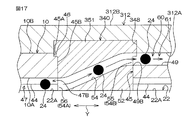
図17および図18は、ボールねじ装置311の模式的な横断面図である。図17は、転動終了位置47B側(図13の右奥側)の収容穴45に装着されるコマ340の接続路54の延びる方向に沿う断面で切断している。図18は、転動開始位置47A側(図13の左手前側)の収容穴45に装着されるコマ340の接続路54の延びる方向に沿う断面で切断している。   17 and 18 are schematic cross-sectional views of the ball screw device 311. FIG. 17 is cut along a cross section along the direction in which the connection path 54 of the top 340 attached to the accommodation hole 45 on the rolling end position 47B side (the right back side in FIG. 13) extends. 18 is cut in a cross section along the direction in which the connection path 54 of the top 340 attached to the accommodation hole 45 on the rolling start position 47A side (the left front side in FIG. 13) extends.

図13および図17に示すように、転動終了位置47B側(図13の右奥側)の収容穴45に装着されるコマ340は、ボールナット10の内周側のボール転動路47から、外周側の旋回転動路60へとボール24を導くために用いられる。このとき、接続路54の内側開口56が入口54Aとして機能し、かつ接続路54の外側開口55が出口54Bとして機能する。   As shown in FIGS. 13 and 17, the top 340 mounted in the accommodation hole 45 on the rolling end position 47 </ b> B side (the right rear side in FIG. 13) extends from the ball rolling path 47 on the inner peripheral side of the ball nut 10. It is used to guide the ball 24 to the rotation path 60 on the outer peripheral side. At this time, the inner opening 56 of the connection path 54 functions as the inlet 54A, and the outer opening 55 of the connection path 54 functions as the outlet 54B.

図13および図18に示すように、転動開始位置47A側(図13の左手前側)の収容穴45に装着されるコマ340は、ボールナット10の外周側の旋回転動路60から、内周側のボール転動路47へとボール24を導くために用いられる。このとき、接続路54の外側開口55が入口54Aとして機能し、かつ接続路54の内側開口56が出口54Bとして機能する。なお、転動開始位置47A側(図13の左手前側)の収容穴45に装着されるコマ340は、転動終了位置47B側(図13の右奥側)の収容穴45に装着されるコマ340と同じ諸元を有している。   As shown in FIGS. 13 and 18, the top 340 mounted in the accommodation hole 45 on the rolling start position 47 </ b> A side (the left front side in FIG. 13) is connected to the inner side of the rotational rotation path 60 on the outer peripheral side of the ball nut 10. It is used to guide the ball 24 to the ball rolling path 47 on the circumferential side. At this time, the outer opening 55 of the connection path 54 functions as the inlet 54A, and the inner opening 56 of the connection path 54 functions as the outlet 54B. Note that the top 340 mounted in the accommodation hole 45 on the rolling start position 47A side (left front side in FIG. 13) is the top mounted in the accommodation hole 45 on the rolling end position 47B side (right rear side in FIG. 13). It has the same specifications as 340.

各コマ340において、第1実施形態に係るコマ40と同様、互いに向きの異なるねじ溝43と外周旋回溝49とを接続路54によって連通させるために、接続路54は、周方向Yに沿う方向に関して「く」の字状に屈曲している。
図13、図17および図18を参照して、第2実施形態に係るボールねじ装置311のボール24の動きについて説明する。ボールねじ装置311では、第1実施形態(図3および図6参照)と同様、ボール転動路47内のボール24は、ボールナット10の回転に伴ってボール転動路47内で転動しながらボール転動路47に沿って、転動開始位置47Aから転動終了位置47Bまで移動する。ボール24は、転動終了位置47Bに到達すると、転動終了位置47B側(図13の右奥側)の収容穴45に装着されるコマ340における接続路54の内側開口56から接続路54内に進入し、この接続路54を通って、ボールナット10の外周面10Bの外周旋回溝49に掬い上げられる。
In each of the tops 340, in the same way as the top 40 according to the first embodiment, the connection path 54 is a direction along the circumferential direction Y in order to connect the screw groove 43 and the outer peripheral turning groove 49 having different directions through the connection path 54. Is bent in the shape of "
The movement of the ball 24 of the ball screw device 311 according to the second embodiment will be described with reference to FIGS. In the ball screw device 311, as in the first embodiment (see FIGS. 3 and 6), the ball 24 in the ball rolling path 47 rolls in the ball rolling path 47 as the ball nut 10 rotates. However, it moves along the ball rolling path 47 from the rolling start position 47A to the rolling end position 47B. When the ball 24 reaches the rolling end position 47B, the ball 24 enters the inside of the connection path 54 from the inner opening 56 of the connection path 54 in the top 340 mounted in the accommodation hole 45 on the rolling end position 47B side (right rear side in FIG. 13). , And passes through the connection path 54 to be scooped up into the outer peripheral turning groove 49 of the outer peripheral surface 10B of the ball nut 10.

その後、ボール24は、外周旋回溝49を含む旋回転動路60を移動してボールナット10の外周を旋回することで、軸方向Xにおいて今までとは逆向き(図13の左手前側)へ進む。そして、旋回転動路60を通ったボール24は、転動開始位置47A側(図13の左手前側)の収容穴45に装着されるコマ340の接続路54の外側開口55(入口54A)から接続路54内に進入し、この接続路54を通って、ボール転動路47内の転動開始位置47Aに戻される。つまり、ボール転動路47内を移動するボール24が、旋回転動路60および接続路54を含む循環路61によって循環され、これにより、ボール転動路47内におけるボール24の安定供給が可能になる。   Thereafter, the ball 24 moves on the rotation path 60 including the outer periphery turning groove 49 and turns on the outer periphery of the ball nut 10, so that the ball 24 moves in the opposite direction in the axial direction X (to the left front side in FIG. 13). move on. Then, the ball 24 that has passed through the rotational movement path 60 passes through the outer opening 55 (inlet 54A) of the connection path 54 of the top 340 mounted in the accommodation hole 45 on the rolling start position 47A side (the left front side in FIG. 13). The vehicle enters the connection path 54, passes through the connection path 54, and returns to the rolling start position 47 </ b> A in the ball rolling path 47. That is, the ball 24 moving in the ball rolling path 47 is circulated by the circulation path 61 including the rotation path 60 and the connection path 54, thereby enabling stable supply of the balls 24 in the ball rolling path 47. become.

以上により第2実施形態によれば、第1実施形態と同様の作用効果を奏する。すなわち、ボール転動路47内における転動終了位置47Bのボール24が、旋回転動路60を含む循環路61によって、ボール転動路47内における転動開始位置47Aに戻されることにより、ボール24を、ボール転動路47内でスムーズに循環させることができる。また、転動開始位置47Aおよび転動終了位置47Bが軸方向Xおよび周方向Yに如何なる相対関係を有していても、転動開始位置47Aと転動終了位置47Bとを循環路61でつなぐことが可能であるので、コマ340の相対的な配置位置に、軸方向Xに沿って延びる貫通孔をボールナット10の周壁10Cに形成する場合のような周方向Yの制約がない。その結果、ボールねじ装置311の理論上の有効巻数をそのまま採用でき、ゆえに、ボールねじ装置311を軸方向Xに小型化することが可能になる。   As described above, according to the second embodiment, the same effects as those of the first embodiment can be obtained. That is, the ball 24 at the rolling end position 47 </ b> B in the ball rolling path 47 is returned to the rolling start position 47 </ b> A in the ball rolling path 47 by the circulation path 61 including the rotation path 60. 24 can be smoothly circulated in the ball rolling path 47. Further, regardless of the relative relationship between the rolling start position 47A and the rolling end position 47B in the axial direction X and the circumferential direction Y, the rolling start position 47A and the rolling end position 47B are connected by the circulation path 61. Therefore, there is no restriction in the circumferential direction Y as in the case where a through hole extending along the axial direction X is formed in the circumferential wall 10C of the ball nut 10 at the relative arrangement position of the top 340. As a result, the theoretical effective number of turns of the ball screw device 311 can be adopted as it is, and therefore the ball screw device 311 can be downsized in the axial direction X.

また、第2実施形態によれば、収容穴45に装着されているコマ340が軸方向溝348に嵌合することにより、円筒312のボールナット10に対する相対回転が阻止される。これにより、他の部材を用いることなく、相対回転阻止構造を設けることができ、これにより、円筒312のボールナット10に対する相対回転を阻止しつつ、部品点数が増加するのを防止できる。   Further, according to the second embodiment, the top 340 mounted in the accommodation hole 45 is fitted into the axial groove 348, so that the cylinder 312 is prevented from rotating relative to the ball nut 10. Thereby, a relative rotation prevention structure can be provided without using other members, and thereby it is possible to prevent the number of parts from increasing while preventing relative rotation of the cylinder 312 with respect to the ball nut 10.

なお、円筒312の内周面312Aに形成される軸方向溝348として、円筒312の軸方向Xの一端(図16の左端)から他端(図16の右端)まで延びる態様(軸方向貫通溝)を例に挙げたが、円筒312の軸方向Xの一端または他端から、軸方向Xの途中部(円筒312における一端と他端との中間位置)までしか延びていない溝を軸方向溝として採用することもできる。この場合、この軸方向溝は、ボールナット10の収容穴45に装着されている2つのコマ340の双方に係合可能な長さを有している必要がある。   As an axial groove 348 formed on the inner peripheral surface 312A of the cylinder 312, an aspect (axial through groove) extending from one end (left end in FIG. 16) to the other end (right end in FIG. 16) of the cylinder 312 in the axial direction X. ) As an example, a groove extending only from one end or the other end in the axial direction X of the cylinder 312 to a middle portion in the axial direction X (an intermediate position between one end and the other end in the cylinder 312) is an axial groove. Can also be adopted. In this case, the axial groove needs to have a length that can be engaged with both of the two tops 340 mounted in the accommodation hole 45 of the ball nut 10.

ところで、前述の図13〜図18に示す第2実施形態では、コマ340が周方向Yに関し揃って配置されるとしたが、コマ340を周方向Yにずらして配置することが可能である。この場合、一対の収容穴45も、周方向Yにずれている。このような第1変形例について図19および図20Aを参照して説明する。
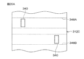
図19および図20Aは、本発明の第2実施形態の第1変形例に係る円筒312Cの構成を示す図である。図19に模式的な横断面図を示し、図20Aに模式的な側面図を示す。
By the way, in the second embodiment shown in FIGS. 13 to 18 described above, the frames 340 are arranged in the circumferential direction Y. However, the frames 340 can be arranged shifted in the circumferential direction Y. In this case, the pair of accommodation holes 45 are also displaced in the circumferential direction Y. Such a first modification will be described with reference to FIGS. 19 and 20A.
19 and 20A are diagrams showing the configuration of a cylinder 312C according to a first modification of the second embodiment of the present invention. FIG. 19 shows a schematic cross-sectional view, and FIG. 20A shows a schematic side view.

円筒312Cが円筒312と相違する点は、係合凹所として、互いに周方向Yにずれた2つの軸方向溝348A,348Bを設けた点である。その他の構成において、円筒312Cと円筒312との間に相違はない。
軸方向溝348Aは、転動開始位置47A側の収容穴45に装着されるコマ340の外部分351を嵌合可能に設けられている。軸方向溝348Aは、それぞれ、軸方向Xに沿って直線状に、円筒312Cの軸方向Xの一端(図20Aの左端)から、円筒312Cの軸方向Xの他端(図20Aの右端)に亘って延びている。軸方向溝348Aは、一定の周方向Yの幅および一定深さに設定されている。円筒312Cがボールナット10に同伴回転可能に設けられる状態において、軸方向溝348Aの径方向外方から見た形状が、転動開始位置47A側の収容穴45の外領域45Aに重複している。軸方向溝348Aの溝幅は、転動開始位置47A側の収容穴45に装着されるコマ340の周方向Yに沿う方向の長さと同じ長さに設定されている。
The difference between the cylinder 312C and the cylinder 312 is that two axial grooves 348A and 348B that are shifted in the circumferential direction Y are provided as engagement recesses. In other configurations, there is no difference between the cylinder 312C and the cylinder 312.
The axial groove 348A is provided so that the outer portion 351 of the top 340 mounted in the accommodation hole 45 on the rolling start position 47A side can be fitted. Each of the axial grooves 348A linearly extends along the axial direction X from one end in the axial direction X of the cylinder 312C (left end in FIG. 20A) to the other end in the axial direction X of the cylinder 312C (right end in FIG. 20A). It extends over. The axial groove 348A is set to have a constant circumferential width Y and a constant depth. In a state where the cylinder 312C is provided so as to be able to rotate along with the ball nut 10, the shape of the axial groove 348A viewed from the outside in the radial direction overlaps the outer region 45A of the accommodation hole 45 on the rolling start position 47A side. . The groove width of the axial groove 348A is set to be the same as the length in the direction along the circumferential direction Y of the top 340 mounted in the accommodation hole 45 on the rolling start position 47A side.

転動開始位置47A側の収容穴45に装着されるコマ340は、その収容状態においてボールナット10の外周面10Bから外方に突出する外部分351が、軸方向溝348Aに嵌合している。
軸方向溝348Bは、転動終了位置47B側の収容穴45に装着されるコマ340の外部分351を嵌合可能に設けられている。軸方向溝348Bは、それぞれ、軸方向Xに沿って直線状に、円筒312Cの軸方向Xの一端(図20Aの左端)から、円筒312Cの軸方向Xの他端(図20Aの右端)に亘って延びている。軸方向溝348Bは、一定の周方向Yの幅および一定深さに設定されている。円筒312Cがボールナット10に同伴回転可能に設けられる状態において、径方向外方から見た形状が、転動終了位置47B側の収容穴45の外領域45Aに重複している。軸方向溝348Bの溝幅は、転動終了位置47B側の収容穴45に装着されるコマ340の周方向Yに沿う方向の長さと同じ長さに設定されている。
The top 340 mounted in the accommodation hole 45 on the rolling start position 47A side has an outer portion 351 that protrudes outward from the outer peripheral surface 10B of the ball nut 10 in the accommodated state, and is fitted in the axial groove 348A. .
The axial groove 348B is provided so that the outer portion 351 of the top 340 mounted in the accommodation hole 45 on the rolling end position 47B side can be fitted. Each of the axial grooves 348B linearly extends along the axial direction X from one end in the axial direction X of the cylinder 312C (left end in FIG. 20A) to the other end in the axial direction X of the cylinder 312C (right end in FIG. 20A). It extends over. The axial groove 348B is set to a constant circumferential width Y and a constant depth. In a state where the cylinder 312C is provided so as to be able to rotate along with the ball nut 10, the shape viewed from the outside in the radial direction overlaps with the outer region 45A of the accommodation hole 45 on the rolling end position 47B side. The groove width of the axial groove 348B is set to the same length as the length in the direction along the circumferential direction Y of the top 340 mounted in the accommodation hole 45 on the rolling end position 47B side.

転動終了位置47B側の収容穴45に装着されるコマ340は、その収容状態においてボールナット10の外周面10Bから外方に突出する外部分351が、軸方向溝348Bに嵌合している。
各収容穴45に装着されているコマ340の軸方向溝348A,348Bへの嵌合により、円筒312Cのボールナット10に対する相対回転が阻止される。換言すると、図19および図20Aに示す第2実施形態の第1変形例では、特許請求の範囲の「相対回転阻止構造」は、軸方向溝348A,348Bとコマ340とを有し、収容穴45に収容されているコマ340の一部が軸方向溝348A,348Bに嵌合(係合)する構造である。
The top 340 mounted in the accommodation hole 45 on the rolling end position 47B side has an outer portion 351 that protrudes outward from the outer peripheral surface 10B of the ball nut 10 in the accommodated state, and is fitted in the axial groove 348B. .
Relative rotation of the cylinder 312C with respect to the ball nut 10 is prevented by fitting the tops 340 mounted in the respective receiving holes 45 into the axial grooves 348A and 348B. In other words, in the first modification of the second embodiment shown in FIGS. 19 and 20A, the “relative rotation blocking structure” in the claims has axial grooves 348A and 348B and a piece 340, and includes a receiving hole. In this structure, a part of the top 340 accommodated in 45 is fitted (engaged) with the axial grooves 348A and 348B.

この場合、理論上の有効巻数をボールねじ装置311にそのまま採用できる。これにより、コマ340の配置位置のレイアウトの自由度を高めることができ、ゆえに、ボールねじ装置311を、より一層、軸方向Xに小型化することができる。
なお、円筒312Cの内周面312Aに形成される軸方向溝348A,348Bとして、円筒312の軸方向Xの一端または他端から、軸方向Xの途中部(円筒312における一端と他端との中間位置)までしか延びていない溝を軸方向溝として採用することもできる。この場合、軸方向溝348Aおよび軸方向溝348Bが、軸方向Xの共通する側の端部(一端または他端)において、その端部に亘って延びている必要がある。また、軸方向溝348Aは、転動開始位置47A側(図13の左手前側)の収容穴45に装着されるコマ340に係合可能な長さを有している必要があり、軸方向溝348Bは、転動終了位置47B側(図13の右奥側)の収容穴45に装着されているコマ340に係合可能な長さを有している必要がある。
In this case, the theoretical effective number of turns can be used as it is in the ball screw device 311. Thereby, the freedom degree of the layout of the arrangement position of the top 340 can be raised, and therefore the ball screw device 311 can be further downsized in the axial direction X.
In addition, as axial grooves 348A and 348B formed on the inner peripheral surface 312A of the cylinder 312C, from one end or the other end in the axial direction X of the cylinder 312 to the middle part in the axial direction X (the one end and the other end in the cylinder 312 A groove extending only to the intermediate position) can also be adopted as the axial groove. In this case, the axial groove 348 </ b> A and the axial groove 348 </ b> B need to extend over the ends (one end or the other end) on the common side in the axial direction X. Further, the axial groove 348A needs to have a length that can be engaged with the top 340 mounted in the accommodation hole 45 on the rolling start position 47A side (the left front side in FIG. 13). 348B needs to have a length that can be engaged with the top 340 mounted in the accommodation hole 45 on the rolling end position 47B side (the right back side in FIG. 13).

また、一対のコマ340の配置位置が周方向Yに関し隔てられているものの、図20Bに示すように、当該一対の配置位置の周方向Yの間隔S0が微小間隔である場合には、円筒312Cの内周面312Aに1つの軸方向溝348Cを設け、軸方向溝348C内に一対のコマ340を収容させるようにしてもよい。これが、第2実施形態の第2変形例である。1つの軸方向溝348Cの溝幅は、周方向Yに関しずれた2つのコマ340を収容可能な大きさに設定されている。この場合、軸方向溝348Cは、第1変形例の軸方向溝348A,348Bを周方向Yにつなげた(一体化させた)ものと換言することができる。   In addition, although the arrangement positions of the pair of pieces 340 are separated with respect to the circumferential direction Y, as shown in FIG. 20B, when the interval S0 in the circumferential direction Y of the pair of arrangement positions is a minute interval, the cylinder 312C One axial groove 348C may be provided on the inner peripheral surface 312A, and the pair of pieces 340 may be accommodated in the axial groove 348C. This is a second modification of the second embodiment. The groove width of one axial groove 348 </ b> C is set to a size that can accommodate two pieces 340 shifted in the circumferential direction Y. In this case, the axial groove 348 </ b> C can be rephrased as one in which the axial grooves 348 </ b> A and 348 </ b> B of the first modification are connected (integrated) in the circumferential direction Y.

なお、一対のコマ340の配置位置が周方向Yに関し一部重複する場合にも、円筒312Cの内周面312Aに1つの軸方向溝(軸方向溝348Cと同等の構成)を設け、当該軸方向溝によって、周方向Yに関しずれた2つのコマ340を収容させるようにしてもよい。
また、第2実施形態において、コマ340内に設けられる接続路として、周方向Yに関しねじ溝43に沿って直線状に延びる接続路54に代えて、接続路154(図10参照)を採用することもできる。この場合、本発明の第1実施形態の第1変形例に係る場合と同様、螺旋状の外周旋回溝49と接続路154とをつなぐ接続溝101が、ボールナット10の外周面10Bに形成され、接続溝101は、接続路154に沿って略直線状に延び、かつ外周旋回溝49の他端49Bにつながっている。
Even when the arrangement positions of the pair of pieces 340 partially overlap with each other in the circumferential direction Y, one axial groove (configuration equivalent to the axial groove 348C) is provided on the inner peripheral surface 312A of the cylinder 312C. You may make it accommodate the two top 340 which shifted | deviated regarding the circumferential direction Y by the direction groove | channel.
In the second embodiment, a connection path 154 (see FIG. 10) is adopted as a connection path provided in the top 340 instead of the connection path 54 extending linearly along the screw groove 43 with respect to the circumferential direction Y. You can also In this case, as in the case of the first modification of the first embodiment of the present invention, the connection groove 101 that connects the spiral outer periphery turning groove 49 and the connection path 154 is formed on the outer peripheral surface 10B of the ball nut 10. The connection groove 101 extends substantially linearly along the connection path 154 and is connected to the other end 49 </ b> B of the outer peripheral turning groove 49.

また、第2実施形態において、コマ340内に設けられる接続路として、接続路54,154に代えて、溝状をなす用いられる接続路254(図12参照)が形成されていてもよい。この場合、本発明の第1実施形態の第3変形例に係る場合と同様、接続路254は、コマ340の長手方向に沿い、コマ340の側壁を突き破るように形成されている。
<第3実施形態>
図21は、本発明の第3実施形態に係るボールねじ装置411の分解斜視図である。図22および図23は、ボールねじ装置411の模式的な縦断面図である。図21では、ボールねじ装置411からねじ軸22を省略した構成を示している。ボールねじ装置411は、たとえば、図1を用いて説明した電動アクチュエータ1と同等の電動アクチュエータに適用される。
In the second embodiment, as a connection path provided in the top 340, instead of the connection paths 54 and 154, a connection path 254 used in a groove shape (see FIG. 12) may be formed. In this case, as in the case of the third modification of the first embodiment of the present invention, the connection path 254 is formed so as to penetrate the side wall of the top 340 along the longitudinal direction of the top 340.
<Third Embodiment>
FIG. 21 is an exploded perspective view of a ball screw device 411 according to the third embodiment of the present invention . 22 and 23 are schematic longitudinal sectional views of the ball screw device 411. FIG. FIG. 21 shows a configuration in which the screw shaft 22 is omitted from the ball screw device 411. The ball screw device 411 is applied, for example, to an electric actuator equivalent to the electric actuator 1 described with reference to FIG.

第3実施形態において、第1実施形態に示された各部に対応する部分には、図1〜図9の場合と同一の参照符号を付して示し、説明を省略する。
図21〜23に示すように、ボールねじ装置411は、ねじ軸22と、ねじ軸22に対して外嵌されたボールナット410と、ねじ軸22とボールナット410との間に介在された複数のボール24と、ボールナット410の外周を包囲する円筒412と、一対のコマ440と、円筒412をボールナット410に連結させるためのキー嵌合構造K1とを含む。キー嵌合構造K1は、ボールナット410の外周面410Bに形成されたボールナット側キー溝(ボールナット側キー凹所)401、円筒412に形成された円筒側キー穴402、ならびにボールナット側キー溝401および円筒側キー穴402に跨って嵌るキー403を有している。
In the third embodiment, parts corresponding to those shown in the first embodiment are denoted by the same reference numerals as those in FIGS. 1 to 9, and description thereof is omitted.
As shown in FIGS. 21 to 23, the ball screw device 411 includes a screw shaft 22, a ball nut 410 externally fitted to the screw shaft 22, and a plurality of members interposed between the screw shaft 22 and the ball nut 410. The ball 24, a cylinder 412 surrounding the outer periphery of the ball nut 410, a pair of pieces 440, and a key fitting structure K 1 for connecting the cylinder 412 to the ball nut 410. The key fitting structure K1 includes a ball nut side keyway (ball nut side key recess) 401 formed on the outer peripheral surface 410B of the ball nut 410, a cylinder side key hole 402 formed in the cylinder 412, and a ball nut side key. A key 403 that fits over the groove 401 and the cylindrical keyhole 402 is provided.

また、この実施形態では、円筒412の内周面412Aが、周方向Yの全域に関し、ボールナット410の外周面410Bとの間に所定の間隔S1(図22および図23参照)を隔てて設けられており、かつ外周旋回溝449が浅溝によって形成されている。この点においても、ボールねじ装置411はボールねじ装置11と相違している。なお、ボールねじ装置411は、理論上必要な有効巻数が2.7であり、その理論上の有効巻数をそのまま採用している。   In this embodiment, the inner peripheral surface 412A of the cylinder 412 is provided with a predetermined interval S1 (see FIGS. 22 and 23) between the outer peripheral surface 410B of the ball nut 410 and the entire circumferential direction Y. The outer peripheral turning groove 449 is formed by a shallow groove. Also in this point, the ball screw device 411 is different from the ball screw device 11. The ball screw device 411 has a theoretically required effective number of turns of 2.7, and adopts the theoretically effective number of turns as it is.

ボールナット410は鋼などの金属を用いて形成され、軸方向Xに延びる筒状体であり、その内周面410Aおよび外周面410Bは、軸方向Xに延びる中心軸を有する円筒面となっている。
ボールナット410の外周面410Bには、外周旋回溝449が形成されている。外周旋回溝449は、外周面410Bの中心軸線を中心として旋回し、軸方向Xの他方(図22の左方)へずれる螺旋状の溝である。外周旋回溝449の一端449A(図21参照)は、転動開始位置47A側(図21の左手前側)の収容穴45を区画している周壁10Cに接続されており、外周旋回溝449の他端449Bは、転動終了位置47B側(図21の右奥側)の収容穴45を区画している周壁10Cに接続されている。外周旋回溝449の断面は略U字状(略半円状)またはコ字状をなしている(図22および図23では略半円状)。外周旋回溝449は、ボール24(図22および図23では黒丸で示す)の内側半分を収容できる溝深さD1(図22および図23参照)を有し、エンドミル等を用いて切削形成される。この溝深さD1において、外周旋回溝449は本発明の第1実施形態に係る外周旋回溝49と相違しており、それ以外の構成は外周旋回溝49と共通している。外周旋回溝449がこのような浅溝であるので、外周旋回溝449に嵌ったボール24の外側半分は、ボールナット410の外周面410Bよりも外側にはみ出す。
The ball nut 410 is formed of a metal such as steel and is a cylindrical body extending in the axial direction X. The inner peripheral surface 410A and the outer peripheral surface 410B are cylindrical surfaces having a central axis extending in the axial direction X. Yes.
An outer peripheral turning groove 449 is formed on the outer peripheral surface 410B of the ball nut 410. The outer peripheral turning groove 449 is a spiral groove that turns around the central axis of the outer peripheral surface 410B and shifts to the other of the axial directions X (left side in FIG. 22). One end 449A (see FIG. 21) of the outer peripheral turning groove 449 is connected to the peripheral wall 10C that defines the accommodation hole 45 on the rolling start position 47A side (the left front side in FIG. 21). The end 449B is connected to the peripheral wall 10C that defines the accommodation hole 45 on the rolling end position 47B side (the right back side in FIG. 21). The cross section of the outer peripheral turning groove 449 is substantially U-shaped (substantially semicircular) or U-shaped (substantially semicircular in FIGS. 22 and 23). The outer peripheral turning groove 449 has a groove depth D1 (see FIGS. 22 and 23) that can accommodate the inner half of the ball 24 (shown by black circles in FIGS. 22 and 23), and is formed by cutting using an end mill or the like. . In this groove depth D1, the outer periphery turning groove 449 is different from the outer periphery turning groove 49 according to the first embodiment of the present invention, and other configurations are common to the outer periphery turning groove 49. Since the outer peripheral turning groove 449 is such a shallow groove, the outer half of the ball 24 fitted in the outer peripheral turning groove 449 protrudes outside the outer peripheral surface 410B of the ball nut 410.

ボールナット410の外周面410Bには、外周旋回溝449の形成位置を除く、軸方向Xおよび周方向Yの途中部に、ボールナット側キー溝401が形成されている。ボールナット側キー溝401は、径方向外方から見た形状が矩形をなしている。
ボールナット側キー溝401および外周旋回溝449を除いて、ボールナット410は、第1実施形態に係るボールナット10とほぼ同等の構成である。すなわち、ボールナット10の内周面10Aには、ねじ溝43が形成されており、また、ボールナット10の内周面10Aの転動開始位置47Aおよび転動終了位置47Bには、ボールナット10の周壁10Cを厚み方向に貫通する2つの収容穴45が形成されている。
On the outer peripheral surface 410B of the ball nut 410, a ball nut-side key groove 401 is formed in the middle of the axial direction X and the circumferential direction Y, excluding the position where the outer peripheral turning groove 449 is formed. The ball nut side keyway 401 has a rectangular shape when viewed from the outside in the radial direction.
Except for the ball nut side keyway 401 and the outer peripheral turning groove 449, the ball nut 410 has a configuration substantially equivalent to that of the ball nut 10 according to the first embodiment. That is, a thread groove 43 is formed in the inner peripheral surface 10A of the ball nut 10, and the ball nut 10 is provided at the rolling start position 47A and the rolling end position 47B of the inner peripheral surface 10A of the ball nut 10. Two housing holes 45 penetrating the peripheral wall 10C in the thickness direction are formed.

図21〜図23に示すように、円筒412は鋼などの金属を用いて形成されている。円筒412の内周面412Aおよび外周面412Bは、それぞれ、ボールナット410の内外周面410A,410Bと同軸を有する円筒面をなしている。換言すると、内周面412Aおよび外周面412Bは、次に述べる円筒側キー穴402が形成される位置を除いて、それぞれ円筒面のみから形成されている。円筒412は、ボールナット410の外周面410B全域をすっぽり包囲した状態で、ボールナット410に同伴回転可能かつ軸方向Xに同伴移動可能に取り付けられている。   As shown in FIGS. 21 to 23, the cylinder 412 is formed using a metal such as steel. The inner circumferential surface 412A and the outer circumferential surface 412B of the cylinder 412 form cylindrical surfaces that are coaxial with the inner and outer circumferential surfaces 410A and 410B of the ball nut 410, respectively. In other words, the inner peripheral surface 412A and the outer peripheral surface 412B are each formed only of a cylindrical surface except for a position where a cylindrical side keyhole 402 described below is formed. The cylinder 412 is attached to the ball nut 410 so as to be able to rotate along with the ball nut 410 and move along with the axial direction X in a state where the entire outer peripheral surface 410B of the ball nut 410 is completely surrounded.

円筒412の内径はボールナット410の外径よりも所定量だけ大きく設定されており、そのため、ボールナット410に対する円筒412の取付状態では、円筒412の内周面412Aが、ボールナット410の外周面410Bとの間に間隔S1(図22および図23参照)を隔てて設けられている。たとえば、間隔S1は、ボール24の直径の半分程度に相当する大きさである。そのため、ボールナット410に円筒412が取り付けられた状態において、円筒412の内周面412Aとボールねじ410の外周面410Bとの間に、円環状の空間SP(図23参照)が形成される。   The inner diameter of the cylinder 412 is set to be larger than the outer diameter of the ball nut 410 by a predetermined amount. Therefore, when the cylinder 412 is attached to the ball nut 410, the inner peripheral surface 412 A of the cylinder 412 is the outer peripheral surface of the ball nut 410. A distance S1 (see FIGS. 22 and 23) is provided between the terminal 410B and 410B. For example, the interval S <b> 1 is a size corresponding to about half of the diameter of the ball 24. Therefore, in a state where the cylinder 412 is attached to the ball nut 410, an annular space SP (see FIG. 23) is formed between the inner peripheral surface 412A of the cylinder 412 and the outer peripheral surface 410B of the ball screw 410.

第3実施形態では、外周旋回溝449と、円筒412の内周面412Aと、外周旋回溝449および内周面412Aの間の空間SPとによって、旋回転動路60が形成される。
円筒412の軸方向Xおよび周方向Yの途中部には、円筒412を厚み方向に貫通する円筒側キー穴402が形成されている。円筒側キー穴402は、円筒412をボールナット410に取り付けた状態において、ボールナット側キー溝401に対向するように配置されている。円筒側キー穴402は、径方向外方から見てボールナット側キー溝401に整合する形状を有している。
In the third embodiment, the rotational path 60 is formed by the outer peripheral turning groove 449, the inner peripheral surface 412A of the cylinder 412 and the space SP between the outer peripheral turning groove 449 and the inner peripheral surface 412A.
A cylindrical side keyhole 402 that penetrates the cylinder 412 in the thickness direction is formed in the middle of the cylinder 412 in the axial direction X and the circumferential direction Y. The cylinder side keyhole 402 is disposed so as to face the ball nut side keyway 401 in a state where the cylinder 412 is attached to the ball nut 410. The cylindrical side keyhole 402 has a shape that matches the ball nut side keyway 401 when viewed from the outside in the radial direction.

キー403はたとえば四角柱状をなしている。ボールナット410のボールナット側キー溝401は、ボールナット410の外周面に沿う平坦な底面404を有している。キー403の長手方向に直交する断面形状および断面寸法は、円筒側キー穴402およびボールナット側キー溝401の形状および断面寸法にそれぞれ整合しており、キー403は、軸方向Xまたは周方向Yにほとんど遊びのない状態で、円筒側キー穴402およびボールナット側キー溝401に嵌合している。   The key 403 has a quadrangular prism shape, for example. The ball nut side keyway 401 of the ball nut 410 has a flat bottom surface 404 along the outer peripheral surface of the ball nut 410. The cross-sectional shape and cross-sectional dimension orthogonal to the longitudinal direction of the key 403 are matched to the shape and cross-sectional dimension of the cylindrical keyhole 402 and the ball nut side keyway 401, respectively. Are fitted in the cylindrical side keyhole 402 and the ball nut side keyway 401 with little play.

図23では、キー403とボールナット側キー溝401との嵌合状態で、キー403の外端面403Aが円筒412の外周面412Bよりも径方向外方に突出している。そして、キー403が外端側からかしめられることによって、キー403が円筒412の外周面412Bに固定される。なお、キー403がボールナット410側に落ちない形状であれば、キー403のかしめは必ずしも必要ではない。   In FIG. 23, the outer end surface 403 </ b> A of the key 403 protrudes outward in the radial direction from the outer peripheral surface 412 </ b> B of the cylinder 412 when the key 403 and the ball nut side keyway 401 are fitted. Then, the key 403 is caulked from the outer end side, whereby the key 403 is fixed to the outer peripheral surface 412B of the cylinder 412. If the key 403 does not fall to the ball nut 410 side, the key 403 is not necessarily caulked.

また、キー403の径方向長さは、ボールナット側キー溝401の溝深さW1と間隔S1とを足し合わせた長さよりも長くなるように設定されていればよい。この場合、ボールナット側キー溝401からキー403が抜けず、キー403とボールナット410との係合が達成され、その結果、ボールナット410に対する円筒412の相対回転および相対軸方向X移動が阻止される。   In addition, the radial length of the key 403 may be set to be longer than the length obtained by adding the groove depth W1 of the ball nut side key groove 401 and the interval S1. In this case, the key 403 cannot be removed from the ball nut side keyway 401, and the engagement between the key 403 and the ball nut 410 is achieved. As a result, the relative rotation of the cylinder 412 with respect to the ball nut 410 and the relative axial X movement are prevented. Is done.

コマ440は小片状をなし、収容穴45と同数(この実施形態では2つ)設けられており、各収容穴45に1つずつ装着される。各コマ440は、収容穴45に収容されており、その状態でボールナット410の外周面410Bから外方に突出する外部分451が、円環状の空間SPに収容される。コマ440の材質としては、第1実施形態に係るコマ40と同様、樹脂や金属などを採用することができる。   The tops 440 are in the form of small pieces, and are provided in the same number as the accommodation holes 45 (two in this embodiment), and one piece is installed in each accommodation hole 45. Each piece 440 is accommodated in the accommodation hole 45, and an outer portion 451 protruding outward from the outer peripheral surface 410B of the ball nut 410 in this state is accommodated in the annular space SP. As the material of the top 440, resin, metal, or the like can be used as in the top 40 according to the first embodiment.

図21に示すように、コマ440は、外部分451と内部分452とを一体的に含んでいる。コマ440には、その内部をトンネル状に延びる接続路54が形成されている。コマ440は、本発明の第1実施形態に係るコマ40の外部分51よりも径方向の厚みの小さい外部分451を設ける点、およびコマ40の内部分52よりも径方向の厚みの小さい内部分452を設ける点において、本発明の第1実施形態に係るコマ40と異なっている。   As shown in FIG. 21, the top 440 integrally includes an outer portion 451 and an inner portion 452. The top 440 is formed with a connection path 54 extending in a tunnel shape. The top 440 is provided with an outer portion 451 having a smaller radial thickness than the outer portion 51 of the top 40 according to the first embodiment of the present invention, and an inner portion having a smaller radial thickness than the inner portion 52 of the top 40. In the point which provides the part 452, it differs from the top 40 which concerns on 1st Embodiment of this invention.

外部分451はブロック状をなしている。外部分451は、円筒412をボールナット410に取り付けた状態において、径方向外方から見て収容穴45の外領域45Aに整合する形状を有しており、たとえば、四隅の端縁が面取りされた直方体状である。なお、外部分451において外側の表面を外面451Aと呼ぶことにすると、この外面451Aが、円筒412の内周面412Aに面一になるように湾曲している。すなわち、円筒412がボールナット410に取り付けられた状態で、コマ440の外部分451の外面451Aが内周面412Aに当接している。コマ440が収容穴45に収容された状態でボールナット410の外周面410Bから突出する外部分451の大きさが、ボールナット410の外周面410Bと円筒412の内周面412Aとの間隔S1とほぼ一致するように、外部分451の径方向厚みが設定されている。   The external portion 451 has a block shape. The external portion 451 has a shape that aligns with the outer region 45A of the receiving hole 45 when viewed from the outside in the radial direction in a state where the cylinder 412 is attached to the ball nut 410. For example, the edges of the four corners are chamfered. It has a rectangular parallelepiped shape. When the outer surface of the outer portion 451 is referred to as an outer surface 451A, the outer surface 451A is curved so as to be flush with the inner peripheral surface 412A of the cylinder 412. That is, with the cylinder 412 attached to the ball nut 410, the outer surface 451A of the outer portion 451 of the top 440 is in contact with the inner peripheral surface 412A. The size of the outer portion 451 protruding from the outer peripheral surface 410B of the ball nut 410 in a state where the top 440 is received in the receiving hole 45 is the distance S1 between the outer peripheral surface 410B of the ball nut 410 and the inner peripheral surface 412A of the cylinder 412. The radial thickness of the outer portion 451 is set so as to substantially match.

内部分452は、外部分451の長手方向に沿って長手のブロック状である。内部分452は、収容穴45の内領域45B(図22参照)にちょうど嵌る形状を有しており、内部分452では、長手方向における両端部が丸められている。外部分451において、外面451Aとは反対側の面を内面451Bと呼ぶことにすると、内部分452は、内面451Bに固定されている。外部分451の厚み方向から見て、内部分452は、外部分451の輪郭の内側に位置している。   The inner portion 452 has a block shape that is long along the longitudinal direction of the outer portion 451. The inner portion 452 has a shape that fits exactly into the inner region 45B (see FIG. 22) of the accommodation hole 45, and both end portions in the longitudinal direction of the inner portion 452 are rounded. In the outer portion 451, when the surface opposite to the outer surface 451A is referred to as an inner surface 451B, the inner portion 452 is fixed to the inner surface 451B. The inner portion 452 is located inside the outline of the outer portion 451 when viewed from the thickness direction of the outer portion 451.

次に、ボールねじ装置411の組付けについて説明する。作業者は、まず、各コマ440を、ボールナット410の収容穴45に、その径方向外側から装着する。コマ440の装着状態では、コマ440の内部分452が、収容穴45の内領域45Bに収容される。また、コマ440の装着状態において、コマ440の外部分451の一部は収容穴45の外領域45Aに収容されるが、コマ440の外部分451の大部分は、ボールナット410の外周面410Bから外方に突出する。   Next, assembly of the ball screw device 411 will be described. The worker first attaches each piece 440 to the accommodation hole 45 of the ball nut 410 from the outside in the radial direction. In the mounted state of the top 440, the inner portion 452 of the top 440 is accommodated in the inner region 45B of the accommodation hole 45. In addition, in the mounted state of the top 440, a part of the outer portion 451 of the top 440 is accommodated in the outer region 45A of the accommodation hole 45, but most of the outer portion 451 of the top 440 is the outer peripheral surface 410B of the ball nut 410. Projecting outward from.

このとき、外部分451の内面451B(外部分451における外面451Aとは反対側の面)の周縁部が、収容穴45における段差部分46に対してボールナット410の径方向外側から当接しており、これによって、コマ440が収容穴45内で位置決めされる。また、長方体形状の外部分451における四隅が外面451A側からかしめられることによって、各コマ440は、ボールナット410の外周面410Bに固定される。なお、外部分451に対するかしめは、四隅の全てでなく、四隅のうちの少なくとも2箇所以上であれば足りる。   At this time, the peripheral edge portion of the inner surface 451B of the outer portion 451 (the surface of the outer portion 451 opposite to the outer surface 451A) is in contact with the stepped portion 46 of the accommodation hole 45 from the radially outer side of the ball nut 410. Thereby, the top 440 is positioned in the accommodation hole 45. Further, each of the tops 440 is fixed to the outer circumferential surface 410B of the ball nut 410 by caulking the four corners of the rectangular outer portion 451 from the outer surface 451A side. The caulking with respect to the outer portion 451 is not limited to all four corners, but may be at least two of the four corners.

また、コマ440をかしめるのでなく、ボールナット410側をかしめることにより、コマ440を収容穴45内に位置決めすることもできる。
さらに、コマ440は、ボールナット410の外周面410Bに固定されていなくてもよい。コマ440は、円筒412の内周面412Aによって、収容穴45からの離脱が防止されており、コマ440を外周面410Bに固定しておかなくても、コマ440の収容穴45への収容状態が保持される。
Further, it is possible to position the top 440 in the accommodation hole 45 by caulking the ball nut 410 side instead of caulking the top 440.
Further, the top 440 may not be fixed to the outer peripheral surface 410B of the ball nut 410. The top 440 is prevented from being detached from the accommodation hole 45 by the inner peripheral surface 412A of the cylinder 412. Even if the top 440 is not fixed to the outer peripheral surface 410B, the top 440 is accommodated in the accommodation hole 45. Is retained.

次いで、コマ440が装着された状態のボールナット410を、円筒412の軸方向Xの一方側または他方側から、軸方向Xに沿って円筒412内に内挿させる。前述のように、コマ440が収容穴45に収容された状態でボールナット410の外周面410Bから突出する外部分451の大きさが、ボールナット410の外周面410Bと円筒412の内周面412Aとの間隔S1とほぼ一致するように、コマ440の径方向厚みが設定されているので、ボールナット410を円筒412に対して軸方向X移動させることができ、これにより、ボールナット410を円筒412内に内挿させることができる。   Next, the ball nut 410 with the top 440 mounted thereon is inserted into the cylinder 412 along the axial direction X from one side or the other side in the axial direction X of the cylinder 412. As described above, the size of the outer portion 451 protruding from the outer peripheral surface 410B of the ball nut 410 in the state in which the top 440 is received in the receiving hole 45 is such that the outer peripheral surface 410B of the ball nut 410 and the inner peripheral surface 412A of the cylinder 412 are. Since the radial thickness of the top 440 is set so as to substantially coincide with the distance S1 between the ball nut 410 and the ball nut 410, the ball nut 410 can be moved in the axial direction X with respect to the cylinder 412. 412 can be interpolated.

そして、ボールナット410および円筒412を相対軸方向X移動および相対回転させて、ボールナット側キー溝401と円筒側キー穴402とを対向させた後、キー403を、円筒側キー穴402およびボールナット側キー溝401に挿入する。挿入されたキー403が、円筒側キー穴402およびボールナット側キー溝401に嵌合することにより、円筒412のボールナット410に対する相対回転が阻止される。換言すると、第3実施形態では、特許請求の範囲の「相対回転阻止構造」は、キー嵌合構造K1である。   Then, the ball nut 410 and the cylinder 412 are moved and rotated relative to each other in the relative axial direction X so that the ball nut side keyway 401 and the cylinder side key hole 402 face each other, and then the key 403 is moved to the cylinder side key hole 402 and the ball. Insert into nut side keyway 401. When the inserted key 403 is fitted into the cylindrical side key hole 402 and the ball nut side key groove 401, relative rotation of the cylinder 412 with respect to the ball nut 410 is prevented. In other words, in the third embodiment, the “relative rotation blocking structure” in the claims is the key fitting structure K1.

転動開始位置47A側(図21の左手前側)の収容穴45に装着されるコマ440と、転動終了位置47B側(図21の右奥側)の収容穴45に装着されるコマ440とは、周方向Yに関し互いに逆向きになるように装着される。転動開始位置47A側(図21の左手前側)の収容穴45には、コマ440の外側開口55が外周旋回溝449の一端449Aに対向するようにコマ440が装着され、転動終了位置47B側(図21の右奥側)の収容穴45には、コマ440の外側開口55が外周旋回溝449の他端449Bに対向するようにコマ440が装着される。   A top 440 mounted in the accommodation hole 45 on the rolling start position 47A side (left front side in FIG. 21), and a top 440 installed in the accommodation hole 45 on the rolling end position 47B side (right rear side in FIG. 21). Are mounted so as to be opposite to each other in the circumferential direction Y. In the accommodation hole 45 on the rolling start position 47A side (the left front side in FIG. 21), the top 440 is mounted so that the outer opening 55 of the top 440 faces the one end 449A of the outer peripheral turning groove 449, and the rolling end position 47B. The top 440 is mounted in the receiving hole 45 on the side (the right back side in FIG. 21) so that the outer opening 55 of the top 440 faces the other end 449 </ b> B of the outer peripheral turning groove 449.

2つのコマ440の接続路54と、外周旋回溝449と円筒12の内周面12Aとによって形成される旋回転動路60とが、軸方向Xにおけるボール転動路47のバイパスとなっている。換言すると、旋回転動路60および2つの接続路54によって、ボール転動路47内の転動終了位置47Bのボール24をボール転動路47内の転動開始位置47Aに戻すための循環路61が形成される。   The connecting path 54 of the two tops 440, the turning rotation path 60 formed by the outer periphery turning groove 449 and the inner peripheral surface 12 A of the cylinder 12 serve as a bypass of the ball rolling path 47 in the axial direction X. . In other words, the circulation path for returning the ball 24 at the rolling end position 47B in the ball rolling path 47 to the rolling start position 47A in the ball rolling path 47 by the turning path 60 and the two connection paths 54. 61 is formed.

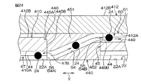
図24および図25は、ボールねじ装置411の模式的な横断面図である。図24は、転動終了位置47B側(図21の右奥側)の収容穴45に装着されるコマ440の接続路54の延びる方向に沿う断面で切断している。図25は、転動開始位置47A側(図21の左手前側)の収容穴45に装着されるコマ440の接続路54の延びる方向に沿う断面で切断している。   24 and 25 are schematic cross-sectional views of the ball screw device 411. FIG. 24 is cut along a cross section along the direction in which the connection path 54 of the top 440 attached to the accommodation hole 45 on the rolling end position 47B side (the right back side in FIG. 21) extends. FIG. 25 is cut along a cross section along the direction in which the connection path 54 of the top 440 mounted in the accommodation hole 45 on the rolling start position 47A side (the left front side in FIG. 21) extends.

図21および図24に示すように、転動終了位置47B側(図21の右奥側)の収容穴45に装着されるコマ440は、ボールナット410の内周側のボール転動路47から、外周側の旋回転動路60へとボール24を導くために用いられる。このとき、接続路54の内側開口56が入口54Aとして機能し、かつ接続路54の外側開口55が出口54Bとして機能する。   As shown in FIGS. 21 and 24, the top 440 mounted in the accommodation hole 45 on the rolling end position 47B side (the right rear side in FIG. 21) is connected to the ball rolling path 47 on the inner peripheral side of the ball nut 410. It is used to guide the ball 24 to the rotation path 60 on the outer peripheral side. At this time, the inner opening 56 of the connection path 54 functions as the inlet 54A, and the outer opening 55 of the connection path 54 functions as the outlet 54B.

図21および図25に示すように、転動開始位置47A側(図21の左手前側)の収容穴45に装着されるコマ440は、ボールナット410の外周側の旋回転動路60から、内周側のボール転動路47へとボール24を導くために用いられる。このとき、接続路54の外側開口55が入口54Aとして機能し、かつ接続路54の内側開口56が出口54Bとして機能する。なお、転動開始位置47A側(図21の左手前側)の収容穴45に装着されるコマ440は、転動終了位置47B側(図21の右奥側)の収容穴45に装着されるコマ440と同じ諸元を有している。   As shown in FIGS. 21 and 25, the top 440 mounted in the accommodation hole 45 on the rolling start position 47A side (the left front side in FIG. 21) is connected to the inner side of the rotational rotation path 60 on the outer peripheral side of the ball nut 410. It is used to guide the ball 24 to the ball rolling path 47 on the circumferential side. At this time, the outer opening 55 of the connection path 54 functions as the inlet 54A, and the inner opening 56 of the connection path 54 functions as the outlet 54B. The top 440 installed in the accommodation hole 45 on the rolling start position 47A side (left front side in FIG. 21) is the top installed in the accommodation hole 45 on the rolling end position 47B side (right rear side in FIG. 21). It has the same specifications as 440.

各コマ440において、第1実施形態に係るコマ40と同様、互いに向きの異なるねじ溝43と外周旋回溝449とを接続路54によって連通させるために、接続路54は、周方向Yに沿う方向に関して「く」の字状に屈曲している。
図21、図24および図25を参照して、第3実施形態に係るボールねじ装置411のボール24の動きについて説明する。ボールねじ装置411では、第1実施形態(図3および図6参照)と同様、ボール転動路47内のボール24は、ボールナット410の回転に伴ってボール転動路47内で転動しながらボール転動路47に沿って、転動開始位置47Aから転動終了位置47Bまで移動する。ボール24は、転動終了位置47Bに到達すると、転動終了位置47B側(図21の右奥側)の収容穴45に装着されるコマ440における接続路54の内側開口56から接続路54内に進入し、この接続路54を通って、ボールナット410の外周面10Bの外周旋回溝449に掬い上げられる。
In each top 440, as in the top 40 according to the first embodiment, the connection path 54 is in the direction along the circumferential direction Y in order to connect the screw groove 43 and the outer peripheral turning groove 449 having different orientations by the connection path 54. Is bent in the shape of "
The movement of the ball 24 of the ball screw device 411 according to the third embodiment will be described with reference to FIGS. In the ball screw device 411, as in the first embodiment (see FIGS. 3 and 6), the ball 24 in the ball rolling path 47 rolls in the ball rolling path 47 as the ball nut 410 rotates. However, it moves along the ball rolling path 47 from the rolling start position 47A to the rolling end position 47B. When the ball 24 reaches the rolling end position 47B, the ball 24 enters the inside of the connection path 54 from the inner opening 56 of the connection path 54 in the top 440 mounted in the accommodation hole 45 on the rolling end position 47B side (the right back side in FIG. 21). , And passes through the connection path 54 to be scooped up into the outer peripheral turning groove 449 of the outer peripheral surface 10B of the ball nut 410.

その後、ボール24は、外周旋回溝449を含む旋回転動路60を移動してボールナット410の外周を旋回することで、軸方向Xにおいて今までとは逆向き(図21の左手前側)へ進む。そして、旋回転動路60を通ったボール24は、転動開始位置47A側(図21の左手前側)の収容穴45に装着されるコマ440の接続路54の外側開口55(入口54A)から接続路54内に進入し、この接続路54を通って、ボール転動路47内の転動開始位置47Aに戻される。つまり、ボール転動路47内を移動するボール24が、旋回転動路60および接続路54を含む循環路61によって循環され、これにより、ボール転動路47内におけるボール24の安定供給が可能になる。   Thereafter, the ball 24 moves on the rotation path 60 including the outer periphery turning groove 449 and turns on the outer periphery of the ball nut 410, so that the ball 24 moves in the opposite direction in the axial direction X (to the left front side in FIG. 21). move on. Then, the ball 24 that has passed through the rotational movement path 60 passes through the outer opening 55 (inlet 54A) of the connection path 54 of the top 440 mounted in the accommodation hole 45 on the rolling start position 47A side (left front side in FIG. 21). The vehicle enters the connection path 54, passes through the connection path 54, and returns to the rolling start position 47 </ b> A in the ball rolling path 47. That is, the ball 24 moving in the ball rolling path 47 is circulated by the circulation path 61 including the rotation path 60 and the connection path 54, thereby enabling stable supply of the balls 24 in the ball rolling path 47. become.

以上により第3実施形態によれば、ボール転動路47内における転動終了位置47Bのボール24が、旋回転動路60を含む循環路61によって、ボール転動路47内における転動開始位置47Aに戻されることにより、ボール24を、ボール転動路47内でスムーズに循環させることができる。また、転動開始位置47Aおよび転動終了位置47Bが軸方向Xおよび周方向Yに如何なる相対関係を有していても、転動開始位置47Aと転動終了位置47Bとを循環路61でつなぐことが可能であるので、コマ440の相対的な配置位置に、軸方向Xに沿って延びる貫通孔をボールナット410の周壁10Cに形成する場合のような周方向Yの制約がない。その結果、ボールねじ装置411の理論上の有効巻数をそのまま採用でき、ゆえに、ボールねじ装置411を軸方向Xに小型化することが可能になる。   As described above, according to the third embodiment, the ball 24 at the rolling end position 47 </ b> B in the ball rolling path 47 is moved to the rolling start position in the ball rolling path 47 by the circulation path 61 including the rotation path 60. By returning to 47A, the ball 24 can be smoothly circulated in the ball rolling path 47. Further, regardless of the relative relationship between the rolling start position 47A and the rolling end position 47B in the axial direction X and the circumferential direction Y, the rolling start position 47A and the rolling end position 47B are connected by the circulation path 61. Therefore, there is no restriction in the circumferential direction Y as in the case where the through hole extending along the axial direction X is formed in the circumferential wall 10C of the ball nut 410 at the relative arrangement position of the top 440. As a result, the theoretical effective number of turns of the ball screw device 411 can be adopted as it is, and therefore the ball screw device 411 can be downsized in the axial direction X.

また、第3実施形態において、コマ440内に設けられる接続路として、周方向Yに関しねじ溝43に沿って直線状に延びる接続路54に代えて、接続路154(図10参照)を採用することもできる。この場合、本発明の第1実施形態の場合と同様、螺旋状の外周旋回溝449と接続路154とをつなぐ接続溝101が、ボールナット410の外周面410Bに形成され、接続溝101は、接続路154に沿って略直線状に延び、かつ外周旋回溝449の他端449Bにつながっている。   In the third embodiment, a connection path 154 (see FIG. 10) is adopted as a connection path provided in the top 440 instead of the connection path 54 extending linearly along the screw groove 43 with respect to the circumferential direction Y. You can also. In this case, as in the case of the first embodiment of the present invention, the connection groove 101 that connects the spiral outer peripheral turning groove 449 and the connection path 154 is formed on the outer peripheral surface 410B of the ball nut 410, and the connection groove 101 is It extends substantially linearly along the connection path 154 and is connected to the other end 449 </ b> B of the outer peripheral turning groove 449.

また、前述の第3実施形態では、コマ440が周方向Yに関し揃って配置されるとしたが、コマ440を周方向Yにずらして配置することができ、この場合、理論上必要な有効巻数をボールねじ装置411にそのまま採用することも可能である。これにより、コマ40の配置位置のレイアウトの自由度を高めることができ、ゆえに、ボールねじ装置411を、より一層、軸方向Xに小型化することができる。   In the third embodiment described above, the frames 440 are arranged in the circumferential direction Y. However, the frames 440 can be arranged shifted in the circumferential direction Y. In this case, the effective number of windings theoretically necessary It is also possible to adopt this as it is for the ball screw device 411. Thereby, the freedom degree of the layout of the arrangement position of the top | top | piece 40 can be raised, Therefore, the ball screw apparatus 411 can be further reduced in the axial direction X further.

また、第3実施形態において、コマ440内に設けられる接続路として、接続路54,154に代えて、溝状をなす接続路254(図12参照)が形成されていてもよい。接続路254は、コマ440の長手方向に沿い、コマ440の側壁を突き破るように形成されている。
以上、この発明の3つの形態について説明したが、本発明は他の形態を採用することもできる。
In the third embodiment, a connection path 254 having a groove shape (see FIG. 12) may be formed as a connection path provided in the top 440 instead of the connection paths 54 and 154. The connection path 254 is formed along the longitudinal direction of the top 440 so as to penetrate the side wall of the top 440.
Although the three forms of the present invention have been described above, the present invention can adopt other forms.

たとえば第1および第2実施形態において、ボールナット10の外周面10Bと円筒12,312の内周面12A,312Aとの間が微小間隔Sである例を例に挙げて説明したが、外周面10Bと内周面12A,312Aとの間が所定の間隔(たとえばボール24の直径の半分程度の大きさであり、図22および図23に示す間隔S1)が設けられていてもよい。この場合、ボールナット10の外周面10Bに形成される外周旋回溝49の溝深さは、ボール24の一部分のみ収容可能な浅溝(たとえば図22および図23の外周旋回溝449の溝深さD1)に設定される。   For example, in the first and second embodiments, the example in which the distance between the outer peripheral surface 10B of the ball nut 10 and the inner peripheral surfaces 12A and 312A of the cylinders 12 and 312 is a minute interval S has been described. A predetermined interval (for example, about half the diameter of the ball 24 and the interval S1 shown in FIGS. 22 and 23) may be provided between 10B and the inner peripheral surfaces 12A and 312A. In this case, the groove depth of the outer periphery turning groove 49 formed on the outer peripheral surface 10B of the ball nut 10 is a shallow groove that can accommodate only a part of the ball 24 (for example, the groove depth of the outer periphery turning groove 449 in FIGS. 22 and 23). D1).

また、第3実施形態において、ボールナット410の外周面410Bと円筒412の内周面412Aとの間が所定大きさの間隔S1である例を例に挙げて説明したが、外周面410Bと内周面412Aとが、微小間隔(たとえば図22および図23に示す間隔S1)を隔てて設けられていてもよい。この場合、ボールナット410の外周面410Bに形成される外周旋回溝449の溝深さは、ボール24の全部分を収容可能な深溝(たとえば図4および図14の外周旋回溝49の溝深さD)に設定される。   In the third embodiment, the example in which the distance S1 between the outer peripheral surface 410B of the ball nut 410 and the inner peripheral surface 412A of the cylinder 412 is a predetermined size has been described as an example. The circumferential surface 412A may be provided with a minute interval (for example, the interval S1 shown in FIGS. 22 and 23). In this case, the groove depth of the outer peripheral turning groove 449 formed on the outer peripheral surface 410B of the ball nut 410 is a deep groove that can accommodate the entire portion of the ball 24 (for example, the groove depth of the outer peripheral turning groove 49 in FIGS. 4 and 14). D).

また、第3実施形態において相対回転阻止構造の一例としてキー嵌合構造K1を例示したが、相対回転阻止構造はキー嵌合構造K1だけに限られない。たとえば、ボールナット410の軸方向Xの端部に、二面幅形状や六角形状からなる係合部を設け、当該係合部に嵌合可能な嵌合部を円筒412の軸方向Xの端部に設け、このような係合部および嵌合部の嵌合により相対回転阻止構造が構成されていてもよい。   In the third embodiment, the key fitting structure K1 is illustrated as an example of the relative rotation preventing structure. However, the relative rotation preventing structure is not limited to the key fitting structure K1. For example, an engaging portion having a two-sided width shape or a hexagonal shape is provided at an end portion of the ball nut 410 in the axial direction X, and a fitting portion that can be fitted to the engaging portion is an end portion in the axial direction X of the cylinder 412. The relative rotation prevention structure may be formed by fitting the engaging portion and the fitting portion.

また、第1〜第3実施形態において、ボールナット10,410において各収容穴45を区画する部分に、ボールナット10,410へのコマ40,340,440の脱落を防止するために段差部分46を形成する構成を採用したが、段差部分46を設けず、各収容穴45を内領域45Bのみで構成するようにしてもよい。
また、第1〜第3実施形態において、外周旋回溝49,449を、ボールナット10,410の外周を一回旋回させる構成を例に挙げて説明したが、1回より多く旋回させる構成であってもよい。また、外周旋回溝49,449を、周方向への旋回数を1周未満(たとえば0.3巻や0.5巻)に設けるようにしてもよい。
Further, in the first to third embodiments, the stepped portion 46 is formed in the portion of the ball nuts 10 and 410 that partitions the receiving holes 45 in order to prevent the tops 40, 340, and 440 from falling off the ball nuts 10 and 410. However, the stepped portion 46 may not be provided, and each receiving hole 45 may be configured only by the inner region 45B.
In the first to third embodiments, the outer periphery turning grooves 49 and 449 have been described by taking as an example a configuration in which the outer periphery of the ball nuts 10 and 410 is turned once. May be. Further, the outer peripheral turning grooves 49 and 449 may be provided so that the number of turns in the circumferential direction is less than one turn (for example, 0.3 turns or 0.5 turns).

また、円筒12,312,412が、転がり軸受13,16の内輪として機能していてもよい。すなわち、円筒12,312,412の外周面12B,312B,412Bに内輪軌道が形成されており、この内輪軌道を軸受け用のボールが転動する構成であってもよい。
その他、特許請求の範囲に記載された事項の範囲で種々の設計変更を施すことが可能である。
Further, the cylinders 12, 312 and 412 may function as inner rings of the rolling bearings 13 and 16. That is, an inner ring raceway may be formed on the outer peripheral surfaces 12B, 312B, and 412B of the cylinders 12, 312, and 412, and a bearing ball may roll on the inner ring raceway.
In addition, various design changes can be made within the scope of matters described in the claims.

10…ボールナット、10A…内周面、10B…外周面、10C…周壁、11…ボールねじ装置、12…円筒、12A…内周面、22…ねじ溝、22A…外周面、24…ボール、40…コマ、41…ねじ溝、43…ねじ溝、45…収容穴(収容凹所)、47…ボール転動路、47A…転動開始位置(収容凹所形成位置)、47B…転動終了位置(収容凹所形成位置)、48…係合穴(係合凹所、相対回転阻止構造)、49…外周旋回溝、54…接続路、60…旋回転動路、61…循環路、154…接続路、311…ボールねじ装置、312…円筒、312A…内周面、340…コマ、348…軸方向溝(係合溝、係合凹所、相対回転阻止構造)、348A…軸方向溝(係合溝、係合凹所、相対回転阻止構造)、348B…軸方向溝(係合溝、係合凹所、相対回転阻止構造)、410…ボールナット、410A…内周面、410B…外周面、411…ボールねじ装置、412…円筒、412A…内周面、440…コマ、449…外周旋回溝、D…外周旋回溝の深さ、D1…外周旋回溝の深さ、K1…キー嵌合構造(相対回転阻止構造)、SP…空間、X…軸方向 DESCRIPTION OF SYMBOLS 10 ... Ball nut, 10A ... Inner peripheral surface, 10B ... Outer peripheral surface, 10C ... Peripheral wall, 11 ... Ball screw apparatus, 12 ... Cylinder, 12A ... Inner peripheral surface, 22 ... Screw groove, 22A ... Outer peripheral surface, 24 ... Ball, 40 ... frame, 41 ... screw groove, 43 ... screw groove, 45 ... accommodation hole (accommodation recess), 47 ... ball rolling path, 47A ... rolling start position (accommodation recess forming position), 47B ... rolling end Position (accommodation recess formation position), 48 ... engagement hole (engagement recess, relative rotation prevention structure), 49 ... outer periphery turning groove, 54 ... connection path, 60 ... turning rotation path, 61 ... circulation path, 154 ... Connection path, 311 ... Ball screw device, 312 ... Cylinder, 312A ... Inner peripheral surface, 340 ... Top, 348 ... Axial groove (engagement groove, engagement recess, relative rotation blocking structure), 348A ... Axial groove (Engagement groove, engagement recess, relative rotation blocking structure), 348B ... axial groove (engagement groove, 410, ball nut, 410A, inner peripheral surface, 410B, outer peripheral surface, 411, ball screw device, 412, cylindrical, 412A, inner peripheral surface, 440, top, 449, outer peripheral swivel. Groove, D: Depth of outer turning groove, D1: Depth of outer turning groove, K1: Key fitting structure (relative rotation blocking structure), SP: Space, X: Axial direction

Claims (6)

外周面にねじ溝が形成されたねじ軸と、
前記ねじ軸に対して外嵌され、内周面にねじ溝が形成されたボールナットと、
前記ボールナットおよび前記ねじ軸の互いのねじ溝によって形成される螺旋状のボール転動路内に転動可能にセットされた複数のボールと、
前記ボールナットの外周を包囲するように設けられた円筒と含み、
前記ボール転動路内において、前記ねじ軸の軸方向に関して間隔を空けた少なくとも2つの収容凹所形成位置には、前記ボールナットの周壁を厚み方向に貫通する収容凹所が形成されており、
前記ボールナットの外周面には、当該ボールナットの外周に沿って螺旋状に旋回する外周旋回溝が形成され、この外周旋回溝と前記円筒の内周面とによって、前記ボールが転動可能な旋回転動路が形成されており、
各収容凹所に収容され、各収容凹所形成位置と前記旋回転動路とを接続する接続路を有するコマと、
前記円筒の内周面に形成された係合凹所を有し、前記収容凹所に収容されている前記コマが前記係合凹所に係合することにより前記円筒の前記ボールナットに対する相対回転を阻止する相対回転阻止構造とをさらに含み、
前記旋回転動路および2つの前記接続路によって、一方の前記収容凹所形成位置の前記ボールを、他方の前記収容凹所形成位置に戻すための循環路が形成される、ボールねじ装置。
A screw shaft having a thread groove formed on the outer peripheral surface;
A ball nut externally fitted to the screw shaft and having a thread groove formed on the inner peripheral surface;
A plurality of balls set so as to roll in a spiral ball rolling path formed by the threaded grooves of the ball nut and the screw shaft;
Including a cylinder provided so as to surround the outer periphery of the ball nut;
In the ball rolling path, at least two housing recess forming positions spaced apart with respect to the axial direction of the screw shaft, a housing recess that penetrates the peripheral wall of the ball nut in the thickness direction is formed,
An outer peripheral turning groove that spirally turns along the outer periphery of the ball nut is formed on the outer peripheral surface of the ball nut, and the ball can roll by the outer peripheral turning groove and the inner peripheral surface of the cylinder. A rotational path is formed,
A top that is housed in each housing recess and has a connection path that connects each housing recess forming position and the rotation path;
The cylinder has an engagement recess formed in the inner peripheral surface of the cylinder, and the top of the cylinder relative to the ball nut is engaged by the piece received in the reception recess being engaged with the engagement recess. And a relative rotation blocking structure for blocking
A ball screw device in which a circulation path for returning the ball at one of the accommodation recess formation positions to the other of the accommodation recess formation positions is formed by the rotational movement path and the two connection paths.
前記係合凹所は、前記円筒の内周面の前記軸方向の途中部で当該円筒を厚み方向に貫通する係合穴を含む、請求項に記載のボールねじ装置。 The engaging recess includes an engaging hole that penetrates the cylinder in the thickness direction in the middle portion of said axial inner circumferential surface of the cylinder, a ball screw device according to claim 1. 前記円筒の前記内周面が、円筒面のみによって形成されている、請求項1または2に記載のボールねじ装置。 The ball screw device according to claim 1 or 2 , wherein the inner peripheral surface of the cylinder is formed only by the cylindrical surface. 前記係合凹所は、前記円筒の内周面に形成され、前記軸方向に沿って延びる係合溝を含む、請求項に記載のボールねじ装置。 The engaging recess is formed on the inner peripheral surface of the cylindrical, including engagement groove extending along the axial direction, the ball screw device according to claim 1. 前記外周旋回溝に前記ボールが収容された状態で前記ボールナットの外周面よりも外側に当該ボールがはみ出ないように、前記外周旋回溝の深さが設定されている、請求項1〜のいずれか一項に記載のボールねじ装置。 Wherein as the ball outside the outer peripheral surface of the state where the ball outer periphery turning groove is accommodated a ball nut does not protrude, the depth of the outer periphery turning groove is set, according to claim 1-4 The ball screw device according to any one of the above. 前記ボールナットおよび前記円筒は、前記ボールナットの外周面と前記円筒の内周面との間に所定の空間が形成されるように設けられており、
前記外周旋回溝に前記ボールが収容された状態で前記ボールナットの外周面よりも外側に当該ボールがはみ出るように、前記外周旋回溝の深さが設定されている、請求項1〜のいずれか一項に記載のボールねじ装置。
The ball nut and the cylinder are provided such that a predetermined space is formed between an outer peripheral surface of the ball nut and an inner peripheral surface of the cylinder,
Wherein as the ball outside the outer peripheral surface of the state where the the outer periphery turning groove ball is accommodated a ball nut protrude, the depth of the outer periphery turning groove is set, any claim 1-4 A ball screw device according to claim 1.
JP2013107273A 2013-03-12 2013-05-21 Ball screw device Expired - Fee Related JP6187807B2 (en)

Priority Applications (4)

Application Number Priority Date Filing Date Title
JP2013107273A JP6187807B2 (en) 2013-03-12 2013-05-21 Ball screw device
EP14158024.1A EP2778476B1 (en) 2013-03-12 2014-03-06 Ball screw device
CN201410081842.4A CN104048010B (en) 2013-03-12 2014-03-07 Ball-screw apparatus
US14/206,594 US9416856B2 (en) 2013-03-12 2014-03-12 Ball screw device

Applications Claiming Priority (3)

Application Number Priority Date Filing Date Title
JP2013049193 2013-03-12
JP2013107273A JP6187807B2 (en) 2013-03-12 2013-05-21 Ball screw device

Publications (2)

Publication Number Publication Date
JP2014199132A JP2014199132A (en) 2014-10-23
JP6187807B2 true JP6187807B2 (en) 2017-08-30

Family

ID=50230999

Family Applications (1)

Application Number Title Priority Date Filing Date
JP2013107273A Expired - Fee Related JP6187807B2 (en) 2013-03-12 2013-05-21 Ball screw device

Country Status (4)

Country Link
US (1) US9416856B2 (en)
EP (1) EP2778476B1 (en)
JP (1) JP6187807B2 (en)
CN (1) CN104048010B (en)

Families Citing this family (27)

* Cited by examiner, † Cited by third party
Publication number Priority date Publication date Assignee Title
EP2018248B1 (en) 2006-05-19 2015-11-04 Applied Medical Resources Corporation Surgical stapler
JP6335271B2 (en) 2013-03-14 2018-05-30 アプライド メディカル リソーシーズ コーポレイション Surgical stapler with partial pocket
ES2863993T3 (en) 2013-03-15 2021-10-13 Applied Med Resources Surgical Stapler with Rotary Shaft Drive Mechanism
ES2803961T3 (en) 2013-03-15 2021-02-01 Applied Med Resources Surgical Stapler with Expandable Jaw
JP2015025544A (en) * 2013-07-29 2015-02-05 株式会社ジェイテクト Ball screw device
EP3154449B1 (en) 2014-06-11 2019-08-14 Applied Medical Resources Corporation Surgical stapler with circumferential firing
CA3211317A1 (en) 2014-09-15 2016-03-24 Applied Medical Resources Corporation Surgical stapler with self-adjusting staple height
FR3028714B1 (en) * 2014-11-25 2017-03-31 Pellenc Sa SCREW MECHANISM AND BALL NUT.
JP7079194B2 (en) 2015-08-06 2022-06-01 アプライド メディカル リソーシーズ コーポレイション Surgical stapler with lock joints
JP2017172605A (en) * 2016-03-18 2017-09-28 Ntn株式会社 Ball Screw
KR20240038159A (en) 2016-04-12 2024-03-22 어플라이드 메디컬 리소시스 코포레이션 Surgical stapler having a powered handle
KR20230074625A (en) 2016-04-12 2023-05-30 어플라이드 메디컬 리소시스 코포레이션 Reload shaft assembly for surgical stapler
ES2878152T3 (en) 2016-04-12 2021-11-18 Applied Med Resources Articulating Mechanism Surgical Stapler
JP6772556B2 (en) * 2016-05-30 2020-10-21 株式会社ジェイテクト Ball screw device and steering device
JP2018062980A (en) * 2016-10-12 2018-04-19 株式会社ジェイテクト Ball screw device, manufacturing method of ball screw device and steering device
JP6805752B2 (en) 2016-11-25 2020-12-23 株式会社ジェイテクト A ball screw device and a steering device equipped with a ball screw device
US11064999B2 (en) 2018-02-27 2021-07-20 Applied Medical Resources Corporation Surgical stapler having a powered handle
KR102185791B1 (en) * 2019-02-26 2020-12-02 덴겐샤토아 가부시키가이샤 Pressing device and welding device
AU2020227757A1 (en) 2019-02-27 2021-08-19 Applied Medical Resources Corporation Surgical stapling instrument having a two-position lockout mechanism
US11717293B2 (en) 2019-03-29 2023-08-08 Applied Medical Resources Corporation Reload cover for surgical stapling system
JP7427873B2 (en) * 2019-06-05 2024-02-06 株式会社ジェイテクト steering unit
CA3163998A1 (en) 2019-12-31 2021-07-08 Applied Medical Resources Corporation Electrosurgical system with tissue and maximum current identification
CN115362316A (en) * 2020-03-31 2022-11-18 固瑞克明尼苏达有限公司 Electrically operated reciprocating pump
JP2022012451A (en) * 2020-07-01 2022-01-17 株式会社ジェイテクト Ball screw device
EP4236821A1 (en) 2020-10-29 2023-09-06 Applied Medical Resources Corporation Surgical stapler having a powered handle
KR20230096077A (en) 2020-10-29 2023-06-29 어플라이드 메디컬 리소시스 코포레이션 Working Shaft Retaining Mechanism for Surgical Stapler
CN114439893A (en) * 2022-01-19 2022-05-06 慈兴集团有限公司 Integral type returns ball lead screw structure

Family Cites Families (26)

* Cited by examiner, † Cited by third party
Publication number Priority date Publication date Assignee Title
GB1050926A (en) * 1900-01-01
GB559407A (en) * 1942-11-28 1944-02-17 Archibald Alexander Baillie Improved nut and screwed spindle for machine and like tools
US5094119A (en) * 1991-03-29 1992-03-10 Robec, Inc. Flexible ribbed, no-backlash ball nut
US5142929A (en) * 1991-03-29 1992-09-01 Robec, Inc. Ball nut with tangential no load-guided return path
JP3390631B2 (en) * 1997-07-18 2003-03-24 Thk株式会社 Ball connector and ball screw device using the same
DE10012810A1 (en) * 2000-03-16 2001-09-27 Rexroth Star Gmbh Rolling body screw drive has at least one re-orientation element fastened to threaded nut encompassing threaded spindle by means of fixing pins extending parallel to spindle's longitudinal axis
US6681651B2 (en) * 2000-07-18 2004-01-27 Thk Co., Ltd. Ball screw
JP2003156117A (en) 2001-11-16 2003-05-30 Nsk Ltd Ball screw device
JP5069555B2 (en) * 2005-02-07 2012-11-07 Thk株式会社 Exercise guidance device
US8015889B2 (en) * 2005-11-15 2011-09-13 Honeywell International Inc. Ballscrew with an integral high-efficiency thrust bearing
US7523682B2 (en) * 2006-03-28 2009-04-28 Hiwin Technologies Corp. Ball screw device having a ball guide member
CN2924180Y (en) * 2006-06-06 2007-07-18 全球滚珠科技股份有限公司 External circulating ball nut
DE102006033852B4 (en) * 2006-07-21 2021-03-25 Robert Bosch Gmbh Lubrication unit
CN101191544A (en) * 2006-11-29 2008-06-04 上银科技股份有限公司 Regurgitation structure for ball screw rod and regurgitation element thereof
US7523681B2 (en) * 2006-12-07 2009-04-28 Hiwin Technologies Corp. Ball screw device having deflecting member background of the invention
US20090090207A1 (en) * 2007-10-07 2009-04-09 Chang Horng Ruey External Circulation Type Ball Screw
CN101842612B (en) * 2007-10-31 2013-10-02 Thk株式会社 Rolling-body screw device
US20090308192A1 (en) * 2008-06-17 2009-12-17 Hiwin Technologies Corp. Ball screw device having bearing members of different load
JP2010071411A (en) * 2008-09-19 2010-04-02 Jtekt Corp Ball screw device and electric power steering device
TWI368697B (en) * 2008-10-31 2012-07-21 Hiwin Tech Corp Circulation element for ball screw
JP5255503B2 (en) * 2009-03-31 2013-08-07 Thk株式会社 Rolling element screw device
US8096201B2 (en) * 2009-05-14 2012-01-17 Hiwin Technologies Corp. Dustproof device for ball screw apparatus
WO2012066693A1 (en) * 2010-11-15 2012-05-24 日本精工株式会社 Ball screw
EP2514999B1 (en) * 2011-04-19 2017-01-25 Aktiebolaget SKF Ball screw assembly with one-piece deflecting elements
US8863601B2 (en) * 2012-02-23 2014-10-21 Hiwin Technologies Corp. Deflecting device for ball screw device
JP5411313B2 (en) * 2012-04-27 2014-02-12 黒田精工株式会社 Ball screw

Also Published As

Publication number Publication date
US9416856B2 (en) 2016-08-16
EP2778476B1 (en) 2015-12-23
CN104048010A (en) 2014-09-17
US20140260746A1 (en) 2014-09-18
CN104048010B (en) 2017-12-29
EP2778476A1 (en) 2014-09-17
JP2014199132A (en) 2014-10-23

Similar Documents

Publication Publication Date Title
JP6187807B2 (en) Ball screw device
US8151959B2 (en) One-way clutch unit
JP2015025544A (en) Ball screw device
JPWO2007114036A1 (en) Ball screw device
US9169910B2 (en) Gear device
US9347534B2 (en) Ball screw device and electric power steering system including the same
JP2014228045A (en) Ball screw device
JP2007255605A (en) Mounting structure of reverse input cutoff clutch
TWI713938B (en) Ball screw spline
JP2014156902A (en) Ball screw device
WO2018143309A1 (en) Steering lock apparatus
JP2016211697A (en) Ball screw nut, ball screw mechanism and actuator
KR20160105879A (en) Gear transmission device
JP2008157374A (en) Ball screw mechanism
JP2015132370A (en) ball screw device
JP2008267523A (en) Ball screw mechanism
JP2005201381A (en) Motor with reduction gear
JP2015143561A (en) ball screw device
JP4426389B2 (en) Ball screw nut
WO2016190206A1 (en) Reverse input blocking clutch
JP2019086067A (en) Ball screw device and steering device
JP2009162264A (en) Ball screw device
JP2015010708A (en) Ball screw device
JP2015113901A (en) Ball screw device
JP2007056993A (en) Planetary roller screw device

Legal Events

Date Code Title Description
A621 Written request for application examination

Free format text: JAPANESE INTERMEDIATE CODE: A621

Effective date: 20160418

A977 Report on retrieval

Free format text: JAPANESE INTERMEDIATE CODE: A971007

Effective date: 20170223

A131 Notification of reasons for refusal

Free format text: JAPANESE INTERMEDIATE CODE: A131

Effective date: 20170302

A521 Request for written amendment filed

Free format text: JAPANESE INTERMEDIATE CODE: A523

Effective date: 20170329

TRDD Decision of grant or rejection written
A01 Written decision to grant a patent or to grant a registration (utility model)

Free format text: JAPANESE INTERMEDIATE CODE: A01

Effective date: 20170706

A61 First payment of annual fees (during grant procedure)

Free format text: JAPANESE INTERMEDIATE CODE: A61

Effective date: 20170719

R150 Certificate of patent or registration of utility model

Ref document number: 6187807

Country of ref document: JP

Free format text: JAPANESE INTERMEDIATE CODE: R150

LAPS Cancellation because of no payment of annual fees