JP6182471B2 - Terahertz wave phase difference measurement system - Google Patents
Terahertz wave phase difference measurement system Download PDFInfo
- Publication number
- JP6182471B2 JP6182471B2 JP2014021836A JP2014021836A JP6182471B2 JP 6182471 B2 JP6182471 B2 JP 6182471B2 JP 2014021836 A JP2014021836 A JP 2014021836A JP 2014021836 A JP2014021836 A JP 2014021836A JP 6182471 B2 JP6182471 B2 JP 6182471B2
- Authority
- JP
- Japan
- Prior art keywords
- terahertz wave
- terahertz
- optical
- delay device
- path length
- Prior art date
- Legal status (The legal status is an assumption and is not a legal conclusion. Google has not performed a legal analysis and makes no representation as to the accuracy of the status listed.)
- Expired - Fee Related
Links
- 238000005259 measurement Methods 0.000 title claims description 47
- 230000003287 optical effect Effects 0.000 claims description 97
- 238000001514 detection method Methods 0.000 claims description 30
- 239000013078 crystal Substances 0.000 claims description 15
- 230000000903 blocking effect Effects 0.000 claims description 3
- 238000000034 method Methods 0.000 description 16
- XUIMIQQOPSSXEZ-UHFFFAOYSA-N Silicon Chemical compound [Si] XUIMIQQOPSSXEZ-UHFFFAOYSA-N 0.000 description 7
- 229910052710 silicon Inorganic materials 0.000 description 7
- 239000010703 silicon Substances 0.000 description 7
- 239000002184 metal Substances 0.000 description 6
- 239000000463 material Substances 0.000 description 5
- 238000007689 inspection Methods 0.000 description 4
- 238000005516 engineering process Methods 0.000 description 3
- 239000000126 substance Substances 0.000 description 3
- 230000005540 biological transmission Effects 0.000 description 2
- 239000010408 film Substances 0.000 description 2
- 230000001678 irradiating effect Effects 0.000 description 2
- 230000010355 oscillation Effects 0.000 description 2
- 238000010422 painting Methods 0.000 description 2
- 239000010409 thin film Substances 0.000 description 2
- 230000002238 attenuated effect Effects 0.000 description 1
- 238000006243 chemical reaction Methods 0.000 description 1
- 150000001875 compounds Chemical class 0.000 description 1
- 230000007547 defect Effects 0.000 description 1
- 230000003111 delayed effect Effects 0.000 description 1
- 230000000694 effects Effects 0.000 description 1
- 239000006261 foam material Substances 0.000 description 1
- 238000003384 imaging method Methods 0.000 description 1
- 239000003973 paint Substances 0.000 description 1
- 230000035699 permeability Effects 0.000 description 1
- 229920000642 polymer Polymers 0.000 description 1
- 102000004169 proteins and genes Human genes 0.000 description 1
- 108090000623 proteins and genes Proteins 0.000 description 1
- 238000011896 sensitive detection Methods 0.000 description 1
- 238000001228 spectrum Methods 0.000 description 1
- 235000000346 sugar Nutrition 0.000 description 1
- 150000008163 sugars Chemical class 0.000 description 1
- -1 sugars and proteins Chemical class 0.000 description 1
- 239000002023 wood Substances 0.000 description 1
Images


Classifications
-
- G—PHYSICS
- G01—MEASURING; TESTING
- G01J—MEASUREMENT OF INTENSITY, VELOCITY, SPECTRAL CONTENT, POLARISATION, PHASE OR PULSE CHARACTERISTICS OF INFRARED, VISIBLE OR ULTRAVIOLET LIGHT; COLORIMETRY; RADIATION PYROMETRY
- G01J9/00—Measuring optical phase difference; Determining degree of coherence; Measuring optical wavelength
- G01J9/02—Measuring optical phase difference; Determining degree of coherence; Measuring optical wavelength by interferometric methods
-
- G—PHYSICS
- G01—MEASURING; TESTING
- G01B—MEASURING LENGTH, THICKNESS OR SIMILAR LINEAR DIMENSIONS; MEASURING ANGLES; MEASURING AREAS; MEASURING IRREGULARITIES OF SURFACES OR CONTOURS
- G01B11/00—Measuring arrangements characterised by the use of optical techniques
- G01B11/02—Measuring arrangements characterised by the use of optical techniques for measuring length, width or thickness
- G01B11/06—Measuring arrangements characterised by the use of optical techniques for measuring length, width or thickness for measuring thickness ; e.g. of sheet material
- G01B11/0616—Measuring arrangements characterised by the use of optical techniques for measuring length, width or thickness for measuring thickness ; e.g. of sheet material of coating
- G01B11/0675—Measuring arrangements characterised by the use of optical techniques for measuring length, width or thickness for measuring thickness ; e.g. of sheet material of coating using interferometry
-
- G—PHYSICS
- G01—MEASURING; TESTING
- G01B—MEASURING LENGTH, THICKNESS OR SIMILAR LINEAR DIMENSIONS; MEASURING ANGLES; MEASURING AREAS; MEASURING IRREGULARITIES OF SURFACES OR CONTOURS
- G01B9/00—Measuring instruments characterised by the use of optical techniques
- G01B9/02—Interferometers
- G01B9/02041—Interferometers characterised by particular imaging or detection techniques
-
- G—PHYSICS
- G01—MEASURING; TESTING
- G01N—INVESTIGATING OR ANALYSING MATERIALS BY DETERMINING THEIR CHEMICAL OR PHYSICAL PROPERTIES
- G01N21/00—Investigating or analysing materials by the use of optical means, i.e. using sub-millimetre waves, infrared, visible or ultraviolet light
- G01N21/17—Systems in which incident light is modified in accordance with the properties of the material investigated
- G01N21/25—Colour; Spectral properties, i.e. comparison of effect of material on the light at two or more different wavelengths or wavelength bands
- G01N21/31—Investigating relative effect of material at wavelengths characteristic of specific elements or molecules, e.g. atomic absorption spectrometry
- G01N21/35—Investigating relative effect of material at wavelengths characteristic of specific elements or molecules, e.g. atomic absorption spectrometry using infrared light
- G01N21/3581—Investigating relative effect of material at wavelengths characteristic of specific elements or molecules, e.g. atomic absorption spectrometry using infrared light using far infrared light; using Terahertz radiation
Landscapes
- Physics & Mathematics (AREA)
- General Physics & Mathematics (AREA)
- Spectroscopy & Molecular Physics (AREA)
- Health & Medical Sciences (AREA)
- Toxicology (AREA)
- Life Sciences & Earth Sciences (AREA)
- Chemical & Material Sciences (AREA)
- Analytical Chemistry (AREA)
- Biochemistry (AREA)
- General Health & Medical Sciences (AREA)
- Immunology (AREA)
- Pathology (AREA)
- Investigating Or Analysing Materials By Optical Means (AREA)
- Length Measuring Devices By Optical Means (AREA)
Description
本発明はテラヘルツ波位相差測定システムに関し、特に、テラヘルツ波を測定対象物に照射し、その反射波あるいは透過波を観測して対象物によって生じた位相の偏差を検出するシステムにおいて、特に対象物の表面凹凸などの形状や、対象物の層、膜の厚さや対象物の空洞などの内部構造、屈折率などを非破壊で観測するために有効なテラヘルツ波位相差測定システムに関する。 The present invention relates to a terahertz wave phase difference measurement system, and more particularly to a system for irradiating a measurement object with a terahertz wave and observing the reflected or transmitted wave to detect a phase deviation caused by the object. The present invention relates to a terahertz wave phase difference measurement system effective for nondestructively observing the shape of the surface irregularities of the surface, the layer of the object, the thickness of the film, the internal structure such as the cavity of the object, and the refractive index.
テラヘルツ波とは、およそ0.1 THz〜10 THzの周波数範囲の電磁波であり、より高い周波数帯の電磁波である遠赤外線と比べて紙や木、プラスチックなどの多くの物質に対する透過性において優れ、一方でより低い周波数帯の電磁波であるミリ波と比べて直進性や分解能において優れている特徴がある。 Terahertz waves are electromagnetic waves in the frequency range of approximately 0.1 THz to 10 THz, and are superior in permeability to many substances such as paper, wood, and plastic compared to far infrared rays, which are electromagnetic waves in a higher frequency band. Compared to millimeter waves, which are electromagnetic waves of a lower frequency band, there is a feature that is superior in straightness and resolution.
また、糖やたんぱく質のような高分子化合物をはじめ、多くの物質の固有スペクトルがテラヘルツ波の周波数帯に含まれている。これらの特徴を生かして、テラヘルツ波を対象物に照射し、その透過波あるいは反射波を観測することで、対象物の形状や内部構造、欠陥・異物の有無、材質や含有成分の違いなどを、透過性のある容器に入れたまま非破壊で観測することが出来る。そのため、材料検査、構造物検査、薬品検査などに適用できる幅広いテラヘルツ波応用技術が将来実現されることを期待されている。 In addition, the intrinsic spectrum of many substances, including polymer compounds such as sugars and proteins, is included in the frequency band of terahertz waves. By taking advantage of these features, irradiating the target with terahertz waves and observing the transmitted or reflected waves, the shape and internal structure of the target, the presence or absence of defects and foreign materials, the difference in materials and components, etc. It can be observed nondestructively in a permeable container. Therefore, a wide range of terahertz wave application technologies that can be applied to material inspection, structure inspection, chemical inspection, etc. are expected to be realized in the future.
特に、測定対象物に反射したテラヘルツ波と基準となる金属などに反射したテラヘルツ波の位相の差を検出することにより、対象物の表面凹凸や層構造の層の厚さ、空洞などの内部構造を非破壊で観測できる。 In particular, by detecting the phase difference between the terahertz wave reflected from the measurement object and the terahertz wave reflected from the reference metal, the internal structure of the surface irregularities of the object, layer thickness of the layer structure, cavities, etc. Can be observed nondestructively.
複数の周波数のテラヘルツ波を用いて、それぞれの周波数の位相差を検出することにより、複数の層の厚さや複雑な内部構造を観測できる。 By detecting the phase difference of each frequency using terahertz waves of a plurality of frequencies, the thickness of the plurality of layers and a complicated internal structure can be observed.
また、測定対象物を透過したテラヘルツ波の位相と対象物のない空間を伝播したテラヘルツ波の位相の差を検出することにより、材料の屈折率を非破壊で観測することができる。 Further, the refractive index of the material can be observed nondestructively by detecting the difference between the phase of the terahertz wave transmitted through the measurement object and the phase of the terahertz wave transmitted through the space without the object.
しかしながら、従来のテラヘルツ波技術では高出力のテラヘルツ波発振器と高感度のテラヘルツ波検出器がなく、なおかつテラヘルツ波の複数の周波数を発生し検出する方法は限られていた。そのため、実用的な測定対象物は絵画・美術品の塗装膜のような薄膜やテラヘルツ波透過性の良い発泡材料などに限られていること、また測定にかかる時間が長いことが大きな課題であった。これらの課題により、高速かつ高精度な測定性能が求められる製品検査装置などにテラヘルツ波技術を導入することは困難であった。 However, in the conventional terahertz wave technology, there is no high-power terahertz wave oscillator and high-sensitivity terahertz wave detector, and there are limited methods for generating and detecting a plurality of frequencies of terahertz waves. For this reason, it is a major issue that practical objects to be measured are limited to thin films such as painting films for paintings and works of art and foam materials with good terahertz wave transmission, and that the measurement takes a long time. It was. Due to these problems, it has been difficult to introduce the terahertz wave technology to a product inspection apparatus or the like that requires high-speed and high-precision measurement performance.
従来のテラヘルツ波の位相差測定システムとして、例えば特許文献1に示すように、テラヘルツパルス波を発生・検出する方法が知られている。フェムト秒レーザの発生する超短パルス光を発生用光伝導アンテナに入射してテラヘルツパルス波を発生させ、検出用光伝導アンテナにテラヘルツパルス波と超短パルス光をほぼ同時に入射し、光伝導アンテナに生じた電流を観測することで二つの光伝導アンテナ間のテラヘルツパルス波の伝達量を得られる。
As a conventional terahertz wave phase difference measurement system, for example, as shown in
この方法を用いて、測定対象物に反射させたテラヘルツパルス波形と、参照となる金属板に反射させたテラヘルツパルス波形とを観測し、それぞれのパルス波形の遅延時間を算出することにより、テラヘルツ波の位相差を得ることができる。よって測定対象物の表面の凹凸、層構造の場合は各層の厚さ、屈折率を測定することができる。 Using this method, the terahertz pulse waveform reflected on the object to be measured and the terahertz pulse waveform reflected on the reference metal plate are observed, and the delay time of each pulse waveform is calculated. The phase difference can be obtained. Therefore, the thickness and refractive index of each layer can be measured in the case of the unevenness of the surface of the measurement object and the layer structure.
また、特許文献2に示すように、狭帯域のテラヘルツ波を発生させ、広帯域のテラヘルツ波検出器で検出する方法が知られている。
Also, as shown in
一方、非特許文献1に示すように、非線形光学結晶をテラヘルツ波発生とテラヘルツ波検出の双方に用いて、狭帯域かつ高強度のテラヘルツ波発生と高感度のテラヘルツ波検出を実現する方法が知られている。
On the other hand, as shown in
しかしながら、特許文献1に記載の技術では、パルス幅の短いテラヘルツパルス波を用いているため強度が小さく十分なSN比が得られない。そのため、塗料の薄膜などテラヘルツ波の透過性の高い測定物への応用に限定されていた。
However, since the technique described in
また、特許文献2に記載の技術では、狭帯域のテラヘルツ波を発生させるため、比較的強度の大きいテラヘルツ波を得られるが、検出にボロメータなどの広帯域のテラヘルツ波検出器を用いているため雑音が大きく十分なSN比が得られない。
In the technique described in
また、非特許文献1に記載の技術では、狭帯域のテラヘルツ波の発生と検出が可能であり、強度に関しておよそ100dBの高いSN比を得られることが示されている。
Further, the technique described in
しかしながら、非特許文献1には位相を検出する方法が示されておらず、特許文献2に記載の技術と異なりポンプ光をテラヘルツ波発生器とテラヘルツ波検出器の双方に照射する必要があるため、ポンプ光の遅延時間とテラヘルツの遅延時間を一致させてテラヘルツ波の位相を測定する構成が必要となる。
However, Non-Patent
図5に具体的な位相測定時の問題点について示す。ポンプ光は非線形結晶の熱による損傷を防ぐために短時間の方が高強度のテラヘルツ波発生に適している。 FIG. 5 shows specific problems at the time of phase measurement. The pump light is suitable for generating a high-intensity terahertz wave for a short time in order to prevent heat damage of the nonlinear crystal.
一方、テラヘルツ波の狭帯域化には一定のパルス幅が必要となり、10GHz帯域幅とするため、およそ400psのパルス幅が用いられている。ポンプ光は、パルス幅の一部の100ps程度がテラヘルツの発生・検出に利用されている。テラヘルツ波は100psのパルス幅であり、その一部の50ps程度が検出に用いられる。 On the other hand, a narrow pulse width of the terahertz wave requires a certain pulse width, and a pulse width of about 400 ps is used to obtain a 10 GHz bandwidth. A part of the pulse width of about 100 ps is used for the generation and detection of terahertz. The terahertz wave has a pulse width of 100 ps, and a portion of about 50 ps is used for detection.
図5の上段に示すように、ポンプ光とテラヘルツ波と光路長が不一致の場合には、テラヘルツ波検出光が発生しない。図5の下段に示すように、ポンプ光のパルス発生時間を遅延させて、ポンプ光とテラヘルツ波のパルスがテラヘルツ波検出器の位置において重なるときにテラヘルツ波検出光が発生される。したがって、ポンプ光とテラヘルツ光の遅延時間を一定の範囲内で一致させる必要がある。 As shown in the upper part of FIG. 5, when the pump light, the terahertz wave, and the optical path length do not match, no terahertz wave detection light is generated. As shown in the lower part of FIG. 5, the pulse generation time of the pump light is delayed, and terahertz wave detection light is generated when the pump light and the terahertz wave pulse overlap at the position of the terahertz wave detector. Therefore, it is necessary to match the delay times of the pump light and the terahertz light within a certain range.
本発明は、以上の課題を検討した結果、SN比の良好なテラヘルツ波の位相差測定を可能とする技術を提供することを目的とする。 As a result of examining the above problems, an object of the present invention is to provide a technique capable of measuring a phase difference of a terahertz wave having a good SN ratio.
このため、本発明では、非線形光学結晶に角度位相整合を満たしたポンプ光とシード光を照射するテラヘルツ波発生器と、非線形光学結晶に角度位相整合を満たしたポンプ光とテラヘルツ波を照射するテラヘルツ波検出器とを用いることで高いSN比を得られるテラヘルツ波発生・検出装置に、ハーフミラーと可動式参照ミラーにより干渉計を構成してテラヘルツ干渉波を観測し位相差を算出する。 For this reason, in the present invention, a terahertz wave generator that irradiates the nonlinear optical crystal with pump light and seed light satisfying angular phase matching, and a terahertz wave that irradiates the nonlinear optical crystal with pump light and terahertz wave that satisfy angular phase matching. A terahertz wave generation / detection device that can obtain a high signal-to-noise ratio by using a wave detector comprises an interferometer composed of a half mirror and a movable reference mirror to observe a terahertz interference wave and calculate a phase difference.
可動式参照ミラーの位置や測定対象物の位置に関わらず、ポンプ光とテラヘルツ波の光路長を一致させるために、第一の光遅延器とマイケルソン干渉計の可動式参照ミラーの移動と連動する第二の光遅延器とをポンプ光の光路上に導入する。 Regardless of the position of the movable reference mirror and the position of the object to be measured, in order to match the optical path lengths of the pump light and the terahertz wave, it is linked with the movement of the movable reference mirror of the first optical delay device and the Michelson interferometer. A second optical delay device is introduced into the optical path of the pump light.
本願において開示される発明のうち代表的なものによって得られる効果を簡単に説明すれば下記の通りである。 The effects obtained by the representative ones of the inventions disclosed in the present application will be briefly described as follows.
すなわち、高感度かつ高精度なテラヘルツ波位相差測定システムを提供することができる。更に、検出した位相差情報に基づき、測定対象の層の厚さ検出、表面形状や内部構造の画像化、屈折率の測定システムを提供することができる。また、テラヘルツ波の光路長の大小に関わらず測定可能となるため、サイズの大きい測定物や、不可視の容器の中にあり反射位置の不明な測定物の測定を可能とする。 That is, a highly sensitive and highly accurate terahertz wave phase difference measurement system can be provided. Furthermore, based on the detected phase difference information, it is possible to provide a thickness detection of the layer to be measured, imaging of the surface shape and internal structure, and a refractive index measurement system. In addition, since measurement is possible regardless of the optical path length of the terahertz wave, it is possible to measure a large-sized measurement object or a measurement object whose reflection position is unknown in an invisible container.
《代表的な実施の形態》
以下、図面に基づいて本発明の実施の形態を説明する。なお、後述する装置構成や処理動作の内容は一例であり、実施の形態と既知の技術との組み合わせや置換により他の実施の形態を実現することもできる。
<Typical embodiment>
Hereinafter, embodiments of the present invention will be described with reference to the drawings. In addition, the content of the apparatus configuration and processing operation to be described later is merely an example, and other embodiments can be realized by combining or replacing the embodiments with known techniques.
なお、この実施の形態では、近赤外光を発生可能な光源をポンプ光源およびシード光源として使用する。ポンプ光源から発生される近赤外光をポンプ光、シード光源から発生される近赤外光をシード光と呼ぶ。 In this embodiment, a light source capable of generating near infrared light is used as a pump light source and a seed light source. Near-infrared light generated from the pump light source is referred to as pump light, and near-infrared light generated from the seed light source is referred to as seed light.
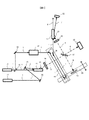
図1にテラヘルツ波位相差測定システムの第一の構成例を示す。ポンプ光パルスレーザ光源13から出力されたポンプ光1は、ビームスプリッタ15により2方向に分岐される。ポンプ光パルスレーザ光源は、単独のレーザ光源である必要はなく、通常は光増幅器をレーザ光源の後段に接続して高出力化し、波長1064nm、パルス幅400ps、出力20mJ/pulse、繰返し周波数100Hzのポンプ光が出力される。
FIG. 1 shows a first configuration example of a terahertz wave phase difference measurement system. The
ビームスプリッタから分岐されたポンプ光の一方は、非線形光学結晶とシリコンプリズム12からなるテラヘルツ波発生器11に入射される。
One of the pump lights branched from the beam splitter is incident on a
また、シード光連続波レーザ光源14から出力されたシード光2は、角度位相整合調整用ミラー28とミラー16を介して、テラヘルツ波発生器11に入射される。シード光連続波レーザ光源は、単独のレーザ光源である必要はなく、通常は波長可変レーザ光源と光増幅器からなり、波長1067nm〜1075nm、出力500mW、連続波のシード光が出力される。角度位相整合調整用ミラー28は、通常回折格子からなり、周波数ごとに異なる角度で反射させて、テラヘルツ波発生器に入射するときには、ポンプ光とシード光の入射角度が、非線形光学結晶内部でテラヘルツパラメトリック発振を起こす角度位相条件を満たすように調整される。
The
角度位相整合調整用ミラー28は、発生周波数ごとに角度を変化させるよう制御されるガルバノミラーでも良い。シリコンプリズムは、非線形光学結晶内部で発生したテラヘルツ波が結晶界面で反射されないよう、屈折率を変えるために結晶表面に接着される。
The angle phase matching
シリコンプリズムから照射されたテラヘルツ波3は楕円状のビーム形状であり、シリンドリカルレンズ18を通過することにより円形のビーム形状となる。
The terahertz wave 3 irradiated from the silicon prism has an elliptical beam shape, and passes through the
ハーフミラー22により、第一の分岐テラヘルツ波4と第二の分岐テラヘルツ波5に分岐され、第一の分岐テラヘルツ波は被測定対象物25に照射され、その反射波が再びハーフミラー22に入射される。ここで、被測定対象物が、透過性が良い材質である場合には、その透過光を金属ミラーで反射させてもよい。
The
一方、第二の分岐テラヘルツ波は、可動式ミラー23に照射され、その反射波が再びハーフミラー22に入射される。
On the other hand, the second branched terahertz wave is applied to the
第一の分岐テラヘルツ反射波と第二の分岐テラヘルツ反射波がハーフミラー22で合成されて干渉波6が出力される。干渉波6は、テラヘルツ波用凸レンズ19を介して集光され、テラヘルツ波検出器21に接着されたシリコンプリズム20に入射される。ビームスプリッタ15で分岐したポンプ光1は、ミラー16を介して第一の光遅延器17に入射される。
The first branched terahertz reflected wave and the second branched terahertz reflected wave are synthesized by the
第一の光遅延器17は、制御信号により任意の光路長に変更することができ、被測定対象物の位置が変わる場合や奥行き方向の測定範囲が大きい場合でもポンプ光の遅延時間をテラヘルツ波の遅延時間と一致させることができる。
The first
次に4個のミラー16のうち、2個のミラーが、可動式参照ミラー23と同じステージ24に設置され、同一方向に動くように構成された第二の光遅延器27にポンプ光が入射される。この構成により、可動式参照ミラーが大きく動く場合においても、ポンプ光とテラヘルツ波の遅延時間を一致させることができる。
Next, of the four mirrors 16, two mirrors are installed on the
非線形光学結晶とシリコンプリズム20からなるテラヘルツ波検出器21に角度位相整合を満たす角度で入射されたポンプ光とテラヘルツ干渉波は、結晶内部でパラメトリック発振が発生し、残存したポンプ光8と、テラヘルツ干渉波の強度に依存して強度が変化するテラヘルツ波検出光7が、テラヘルツ干渉波の周波数に依存した角度位相整合を満たす角度で照射される。
The pump light and the terahertz interference wave incident on the
テラヘルツ波検出光の強度を、フォトダイオード、焦電センサ、ボロメータ、あるいはCCDなどの光検出器26で測定する。テラヘルツ干渉波の強度は、光検出器で測定したテラヘルツ波検出光の強度から算出する。
The intensity of the terahertz wave detection light is measured by a
ここで、位相差の測定方法について説明する。テラヘルツ干渉波は、第一の分岐テラヘルツ波の光路長と、第二の分岐テラヘルツ波の光路長が一致したときに強度が最大となり、第一の分岐テラヘルツ波の光路長と、第二の分岐テラヘルツ波の光路長の差が1/2波長となったときに強度が最小となる。 Here, a method for measuring the phase difference will be described. The terahertz interference wave has the maximum intensity when the optical path length of the first branched terahertz wave matches the optical path length of the second branched terahertz wave, the optical path length of the first branched terahertz wave, and the second branch The intensity is minimized when the difference in optical path length of the terahertz wave is ½ wavelength.
あらかじめ、基準となる位置に、測定対象物の代わりに金属板等の反射物を設置し、ステージ24を走査してステージ位置ごとの干渉波の強度分布を測定し記録する。テラヘルツ波の波長と同じ周期で干渉波形が記録され、これを標準位相の干渉波形とする。次に、被測定対象物を設置し、ステージ24を走査して同様に干渉波形を記録する。標準位相の干渉波形と被測定対象物の干渉波形の最大強度の位置の差が、テラヘルツ波の位相差となる。また、この位置の差は、テラヘルツ波の反射波が往復する距離の基準と被測定対象物の差であり、基準となる位置からの奥行き方向の偏差の2倍に当たる。
In advance, a reflector such as a metal plate is installed at a reference position instead of the object to be measured, and the
したがって、位相差からテラヘルツ波の反射位置の特定が可能であり、測定対象物をテラヘルツ波の光軸に対して水平、あるいは垂直方向に動かしながら位相差を記録すると、立体形状の画像化が可能となる。また、複数の周波数の干渉波形を記録しフーリエ変換すると、特許文献2に示されているように複数の反射位置を算出することができる。
Therefore, the reflection position of the terahertz wave can be specified from the phase difference, and if the phase difference is recorded while moving the measurement object horizontally or vertically with respect to the optical axis of the terahertz wave, a three-dimensional shape can be imaged. It becomes. Further, when interference waveforms having a plurality of frequencies are recorded and Fourier transformed, a plurality of reflection positions can be calculated as disclosed in
図2にテラヘルツ波位相差測定システムの第二の構成例を示す。第一の構成例と異なり、ポンプ光パルスレーザ光源13から、分岐せずにテラヘルツ波発生器11に入射される。ポンプ光パルスレーザ光源の出力する強度を落とさずにポンプ光をテラヘルツ波発生器に照射できるため、同じパワーの光源を用いた場合、テラヘルツ波の発生強度を向上させることができる。
FIG. 2 shows a second configuration example of the terahertz wave phase difference measurement system. Unlike the first configuration example, the light is incident on the
テラヘルツ波発生器を通過したポンプ光1は、第一の光遅延回路17と、第二の光遅延回路27を介して、テラヘルツ波検出器21に入射される。テラヘルツ波発生器を通過した際に、ポンプ光の強度は減衰しているため、テラヘルツ波検出器に入射するポンプ光強度は低下する。光学部品点数が少なくてすむため、測定器の構築が容易である利点がある。
The
図3にテラヘルツ波位相差測定システムの第三の構成例を示す。第一の構成例と異なり、第二の分岐テラヘルツ波5の経路上にテラヘルツ波のシャッター29を設ける。
FIG. 3 shows a third configuration example of the terahertz wave phase difference measurement system. Unlike the first configuration example, a
シャッターは金属板を開閉したり、電動式の絞りを開閉したり、あるいは回転式の光学フィルタ切替器に設置した金属遮断板の有無を切り替えてもよい。 The shutter may open / close a metal plate, open / close an electric diaphragm, or switch the presence / absence of a metal blocking plate installed in a rotary optical filter switch.
このシャッターを設けることにより、例えば不可視の容器に包まれていて測定対象物の位置が不明確な場合に、測定対象物を測定するのに最適なステージ移動範囲となるよう、光遅延器や可動式参照ミラーの初期位置を設定することが可能となる。 By providing this shutter, for example, when the position of the measurement object is unclear because it is wrapped in an invisible container, an optical delay device or a movable element is used so that the stage moving range is optimal for measuring the measurement object. It is possible to set the initial position of the expression reference mirror.
その手順を図6にフローチャートとして示す。まず、シャッターを遮断する。この状態で第一の光遅延器を走査し、図5に示した光路長不一致時の状態ではなく、光路長一致時のテラヘルツ波検出光が検出される位置を記録し、その中心に第一の光遅延器の光路長を設定する。 The procedure is shown as a flowchart in FIG. First, shut off the shutter. In this state, the first optical delay device is scanned, and the position at which the terahertz wave detection light is detected when the optical path length is coincident is recorded instead of the optical path length inconsistent state shown in FIG. The optical path length of the optical delay unit is set.
次に、シャッターを開放し、第一の光遅延器と第二の光遅延器の両方をそれぞれ逆方向に走査する。すなわち、第一の光遅延器の光路長を延ばしたときには、第二の光遅延器の光路長を縮小する。 Next, the shutter is opened, and both the first optical delay device and the second optical delay device are scanned in the opposite directions. That is, when the optical path length of the first optical delay device is extended, the optical path length of the second optical delay device is reduced.
そして、二つの光遅延器の合計光路長は一定となるようにする。このとき、ステージ24の位置ごとのテラヘルツ干渉波の強度を記録して最も強い強度となるステージ位置を第二の光遅延器の光路長の初期値として設定する。
The total optical path length of the two optical delay devices is made constant. At this time, the intensity of the terahertz interference wave for each position of the
次に、シャッターを開放したまま、第二の光遅延器のみを前後に走査する。前の手順において、干渉波形のピーク位置、すなわち第一の分岐テラヘルツ波の光路長と第二の分岐テラヘルツ波の光路長が一致した状態を初期位置としているため、その前後を走査すれば反射物の奥行き方向の反射位置前後を測定することになり。最適なステージ移動範囲となる。このようにして、容器内の見えない被測定物の位置を、測定波形から推定し、最適な位相差測定を実施することが可能となる。 Next, only the second optical delay device is scanned back and forth with the shutter opened. In the previous procedure, the peak position of the interference waveform, that is, the state where the optical path length of the first branched terahertz wave and the optical path length of the second branched terahertz wave coincide with each other as the initial position. Measured before and after the reflection position in the depth direction. The optimal stage movement range. In this way, the position of the invisible object to be measured in the container can be estimated from the measurement waveform, and the optimum phase difference measurement can be performed.
図4にテラヘルツ波位相差測定システムの第四の構成例を示す。 FIG. 4 shows a fourth configuration example of the terahertz wave phase difference measurement system.
第二の構成例のポンプ光を分離しない場合において、第二の分岐テラヘルツ波5の経路上にシャッター29を設ける。第三の構成例と同様に、図6のフローチャートに従い測定を実施することにより、容器内の見えない測定物の位置を、測定波形から推定し、最適な位相差測定を実施することが可能となる。
When the pump light of the second configuration example is not separated, a
1 ポンプ光
2 シード光
3 テラヘルツ波
4 第一の分岐テラヘルツ波
5 第二の分岐テラヘルツ波
6 第一の分岐テラヘルツ波と第二の分岐テラヘルツ波の合成干渉波
7 テラヘルツ波検出光
8 ポンプ光
11 テラヘルツ波発生器
12 シリコンプリズム
13 ポンプ光パルスレーザ光源
14 シード光連続波レーザ光源
15 ビームスプリッタ
16 ミラー
17 第一の光遅延器
18 テラヘルツ波用シリンドリカルレンズ
19 テラヘルツ波用凸レンズ
20 シリコンプリズム
21 テラヘルツ波検出器
22 テラヘルツ波用ハーフミラー
23 可動式参照ミラー
24 可動式ステージ
25 測定対象物
26 光検出器
27 第二の光遅延器
28 角度位相整合調整ミラー
29 テラヘルツ波用シャッター
DESCRIPTION OF
Claims (4)
シード光を発生させる連続波レーザ光源と、
前記ポンプ光と前記シード光とを、テラヘルツ波を発生させるための第一の角度位相整合条件を満たすように入射させることにより、テラヘルツ波を発生する非線形光学結晶からなるテラヘルツ波発生器と、
前記テラヘルツ波と前記ポンプ光とを、前記テラヘルツ波からテラヘルツ波検出光への変換するための第二の角度位相整合条件を満たすように入射させることにより、前記テラヘルツ波検出光を発生する非線形光学結晶からなるテラヘルツ波検出器と、
前記検出光を検出する光検出器と、
前記光検出器の出力信号を検出したテラヘルツ波の強度に変換して記録する信号処理装置と、
前記パルスレーザ光源からのポンプ光を2方向に分岐し、分岐した第一のポンプ光を前記テラヘルツ波発生器に導き、分岐した第二のポンプ光を第一の光遅延器へと導く、ビームスプリッタと、
前記第二のポンプ光の光路上に設置し、前記テラヘルツ波検出器へと導く、前記第一の光遅延器および第二の光遅延器と、
前記テラヘルツ波発生器から照射されたテラヘルツ波を2方向に分岐するとともに、それぞれの2方向から反射されたテラヘルツ波を合成して前記テラヘルツ波検出器に導くハーフミラーと、前記ハーフミラーの第一の方向に分岐したテラヘルツ波を測定対象物に照射して、反射されたテラヘルツ波をハーフミラーに導くテラヘルツ波光学系と、前記ハーフミラーの第二の方向に分岐したテラヘルツ波を任意の光路長で反射してハーフミラーに導く可動式参照ミラーとからなるテラヘルツ波干渉計と、
前記第二の光遅延器の前記第二のポンプ光の光路長可変量と前記可動式参照ミラーのテラヘルツ波の光路長可変量が一致する連動機構とを有し、
前記ビームスプリッタから前記テラヘルツ波発生器までの第一のポンプ光の光路長と前記ビームスプリッタから第一の光遅延器と第二の光遅延器を通過し前記テラヘルツ波検出器までの第二のポンプ光の光路長との差分である第一の光路長と、前記テラヘルツ波発生器からハーフミラーで分岐され第二の方向を通り可動式ミラーで反射されハーフミラーを再度通過し、前記テラヘルツ検出器に至るまでのテラヘルツ波の光路長である第二の光路長が実質的に一致することを特徴とするテラヘルツ波位相差測定システム。 A pulsed laser light source for generating pump light;
A continuous wave laser light source for generating seed light;
A terahertz wave generator composed of a nonlinear optical crystal that generates a terahertz wave by causing the pump light and the seed light to be incident so as to satisfy a first angular phase matching condition for generating the terahertz wave;
Nonlinear optics for generating the terahertz wave detection light by making the terahertz wave and the pump light incident so as to satisfy a second angular phase matching condition for converting the terahertz wave to the terahertz wave detection light A terahertz wave detector made of crystals;
A photodetector for detecting the detection light;
A signal processing device for converting and recording the detected output signal of the photodetector into the intensity of the detected terahertz wave;
A beam that branches the pump light from the pulse laser light source in two directions, guides the branched first pump light to the terahertz wave generator, and guides the branched second pump light to the first optical delay device A splitter,
The first optical delay device and the second optical delay device installed on the optical path of the second pump light and led to the terahertz wave detector;
A half mirror that branches the terahertz wave emitted from the terahertz wave generator in two directions, combines the terahertz waves reflected from the two directions and guides the terahertz wave to the terahertz wave detector, and a first of the half mirrors A terahertz wave optical system that irradiates a target object with a terahertz wave branched in the direction of, and guides the reflected terahertz wave to a half mirror, and a terahertz wave branched in the second direction of the half mirror to an arbitrary optical path length A terahertz wave interferometer consisting of a movable reference mirror that is reflected by and guided to a half mirror,
An interlocking mechanism in which the optical path length variable amount of the second pump light of the second optical delay device and the optical path length variable amount of the terahertz wave of the movable reference mirror match,
An optical path length of the first pump light from the beam splitter to the terahertz wave generator and a second path from the beam splitter to the terahertz wave detector through the first optical delay device and the second optical delay device. The first optical path length, which is the difference between the optical path length of the pump light, and the terahertz wave generator branch off from the terahertz wave generator by the half mirror, pass through the second direction and reflected by the movable mirror, and pass through the half mirror again to detect the terahertz A terahertz wave phase difference measurement system characterized in that the second optical path length, which is the optical path length of the terahertz wave leading up to the vessel, substantially matches.
第一の測定において、第二の分岐テラヘルツ波をシャッターで遮断し、第一の光遅延器を走査して検出光のピークを検出した位置を第一の光遅延器の初期位置とし、第二の測定において、シャッターを開放して第一の分岐テラヘルツ波を通過させ、第一の光遅延器と第二の光遅延器をポンプ光の光路長が一定になるように走査して、検出光の最小値となる位置を第二の光遅延器の初期位置とし、
第三の測定において、第一の分岐テラヘルツ波を通過させ、第一の光遅延器を固定し、第二の光遅延器を走査して検出光の強度を観測して測定対象物によるテラヘルツ波の位相差を測定することを特徴とするテラヘルツ波位相差測定システム。 The terahertz interferometer according to claim 1, further comprising a shutter that switches between passing and blocking terahertz waves between the half mirror and the movable reference mirror.
In the first measurement, the position where the second branched terahertz wave is blocked by the shutter, the first optical delayer is scanned and the peak of the detection light is detected is set as the initial position of the first optical delayer, In this measurement, the shutter is opened to pass the first branched terahertz wave, the first optical delay device and the second optical delay device are scanned so that the optical path length of the pump light is constant, and the detection light is detected. Is the initial position of the second optical delay,
In the third measurement, the first branched terahertz wave is passed, the first optical delay device is fixed, the second optical delay device is scanned, the intensity of the detected light is observed, and the terahertz wave generated by the measurement object is measured. A terahertz wave phase difference measurement system characterized by measuring the phase difference of the THz wave.
シード光を発生させる連続波レーザ光源と、
前記ポンプ光と前記シード光とを、テラヘルツ波を発生させるための第一の角度位相整合条件を満たすように入射させることにより、テラヘルツ波を発生する非線形光学結晶からなるテラヘルツ波発生器と、
前記テラヘルツ波と前記ポンプ光とを、前記テラヘルツ波からテラヘルツ波検出光への変換するための第二の角度位相整合条件を満たすように入射させることにより、前記テラヘルツ波検出光を発生する非線形光学結晶からなるテラヘルツ波検出器と、
前記検出光を検出する光検出器と、
前記光検出器の出力信号を検出したテラヘルツ波の強度に変換して記録する信号処理装置と、
前記パルスレーザ光源から照射されて前記テラヘルツ発生器を通過したポンプ光を、前記テラヘルツ波検出器へと導く、前記第一の光遅延器および第二の光遅延器と、
前記テラヘルツ波発生器から照射されたテラヘルツ波を2方向に分岐するとともに、それぞれの2方向から反射されたテラヘルツ波を合成して前記テラヘルツ波検出器に導くハーフミラーと、前記ハーフミラーの第一の方向に分岐したテラヘルツ波を測定対象物に照射して、反射されたテラヘルツ波をハーフミラーに導くテラヘルツ波光学系と、前記ハーフミラーの第二の方向に分岐したテラヘルツ波を任意の光路長で反射してハーフミラーに導く可動式参照ミラーとからなるテラヘルツ波干渉計と、
前記第二の光遅延器の前記ポンプ光の光路長可変量と前記可動式参照ミラーのテラヘルツ波の光路長可変量が一致する連動機構とを有し、
前記テラヘルツ波発生器から第一の光遅延器と第二の光遅延器を通過し前記テラヘルツ波検出器までのポンプ光の光路長である第一の光路長と、前記テラヘルツ波発生器からハーフミラーで分岐され第二の方向を通り可動式ミラーで反射されハーフミラーを再度通過し、前記テラヘルツ検出器に至るまでのテラヘルツ波の光路長である第二の光路長が実質的に一致することを特徴とするテラヘルツ波位相差測定システム。 A pulsed laser light source for generating pump light;
A continuous wave laser light source for generating seed light;
A terahertz wave generator composed of a nonlinear optical crystal that generates a terahertz wave by causing the pump light and the seed light to be incident so as to satisfy a first angular phase matching condition for generating the terahertz wave;
Nonlinear optics for generating the terahertz wave detection light by making the terahertz wave and the pump light incident so as to satisfy a second angular phase matching condition for converting the terahertz wave to the terahertz wave detection light A terahertz wave detector made of crystals;
A photodetector for detecting the detection light;
A signal processing device for converting and recording the detected output signal of the photodetector into the intensity of the detected terahertz wave;
The first optical delay device and the second optical delay device that guide the pump light irradiated from the pulse laser light source and passed through the terahertz generator to the terahertz wave detector,
A half mirror that branches the terahertz wave emitted from the terahertz wave generator in two directions, combines the terahertz waves reflected from the two directions and guides the terahertz wave to the terahertz wave detector, and a first of the half mirrors A terahertz wave optical system that irradiates a target object with a terahertz wave branched in the direction of, and guides the reflected terahertz wave to a half mirror, and a terahertz wave branched in the second direction of the half mirror to an arbitrary optical path length A terahertz wave interferometer consisting of a movable reference mirror that is reflected by and guided to a half mirror,
An interlocking mechanism in which the optical path length variable amount of the pump light of the second optical delay device and the optical path length variable amount of the terahertz wave of the movable reference mirror match,
A first optical path length which is an optical path length of pump light from the terahertz wave generator through the first optical delay device and the second optical delay device to the terahertz wave detector, and a half from the terahertz wave generator. The second optical path length, which is the optical path length of the terahertz wave leading to the terahertz detector, substantially matches with the branching mirror, passing through the second direction, reflected by the movable mirror, and again passing through the half mirror. Terahertz wave phase difference measurement system.
第一の測定において、第二の分岐テラヘルツ波をシャッターで遮断し、第一の光遅延器を走査して検出光のピークを検出した位置を第一の光遅延器の初期位置とし、第二の測定において、シャッターを開放して第一の分岐テラヘルツ波を通過させ、第一の光遅延器と第二の光遅延器をポンプ光の光路長が一定になるように走査して、検出光の最小値となる位置を第二の光遅延器の初期位置とし、
第三の測定において、第一の分岐テラヘルツ波を通過させ、第一の光遅延器を固定し、第二の光遅延器を走査して検出光の強度を観測し,測定対象物によるテラヘルツ波の位相差を測定することを特徴とするテラヘルツ波位相差測定システム。 The terahertz interferometer according to claim 3, further comprising a shutter that switches between passing and blocking terahertz waves between the half mirror and the movable reference mirror,
In the first measurement, the position where the second branched terahertz wave is blocked by the shutter, the first optical delayer is scanned and the peak of the detection light is detected is set as the initial position of the first optical delayer, In this measurement, the shutter is opened to pass the first branched terahertz wave, the first optical delay device and the second optical delay device are scanned so that the optical path length of the pump light is constant, and the detection light is detected. Is the initial position of the second optical delay,
In the third measurement, the first branched terahertz wave is passed, the first optical delay device is fixed, the second optical delay device is scanned, the intensity of the detected light is observed, and the terahertz wave generated by the measurement object is measured. A terahertz wave phase difference measurement system characterized by measuring the phase difference of the THz wave.
Priority Applications (4)
| Application Number | Priority Date | Filing Date | Title |
|---|---|---|---|
| JP2014021836A JP6182471B2 (en) | 2014-02-07 | 2014-02-07 | Terahertz wave phase difference measurement system |
| EP14881674.7A EP3104165B1 (en) | 2014-02-07 | 2014-09-22 | Terahertz wave phase difference measurement device |
| US15/116,331 US9835494B2 (en) | 2014-02-07 | 2014-09-22 | Terahertz wave phase difference measurement device |
| PCT/JP2014/075080 WO2015118717A1 (en) | 2014-02-07 | 2014-09-22 | Terahertz wave phase difference measurement device |
Applications Claiming Priority (1)
| Application Number | Priority Date | Filing Date | Title |
|---|---|---|---|
| JP2014021836A JP6182471B2 (en) | 2014-02-07 | 2014-02-07 | Terahertz wave phase difference measurement system |
Publications (2)
| Publication Number | Publication Date |
|---|---|
| JP2015148523A JP2015148523A (en) | 2015-08-20 |
| JP6182471B2 true JP6182471B2 (en) | 2017-08-16 |
Family
ID=53777537
Family Applications (1)
| Application Number | Title | Priority Date | Filing Date |
|---|---|---|---|
| JP2014021836A Expired - Fee Related JP6182471B2 (en) | 2014-02-07 | 2014-02-07 | Terahertz wave phase difference measurement system |
Country Status (4)
| Country | Link |
|---|---|
| US (1) | US9835494B2 (en) |
| EP (1) | EP3104165B1 (en) |
| JP (1) | JP6182471B2 (en) |
| WO (1) | WO2015118717A1 (en) |
Families Citing this family (10)
| Publication number | Priority date | Publication date | Assignee | Title |
|---|---|---|---|---|
| GB2556249B (en) * | 2015-07-22 | 2021-08-18 | Hitachi High Tech Corp | Far-infrared spectroscopy device |
| JP2017078599A (en) * | 2015-10-19 | 2017-04-27 | フェムトディプロイメンツ株式会社 | Terahertz time-resolved spectroscopy apparatus |
| JP6401694B2 (en) * | 2015-12-11 | 2018-10-10 | 日本電信電話株式会社 | Dielectric spectrometer |
| JP7204085B2 (en) * | 2017-08-10 | 2023-01-16 | 株式会社トプコン | Terahertz wave generation method and terahertz wave generator |
| JP6742527B2 (en) * | 2017-08-22 | 2020-08-19 | 株式会社日立ハイテク | Far infrared spectroscopy device and far infrared spectroscopy method |
| US11499813B2 (en) * | 2017-10-09 | 2022-11-15 | Nederlandse Organisatie Voor Toegepast-Natuurwetenschappelijk Onderzoek Tno | Refocusing device |
| DE112017008083B4 (en) | 2017-12-13 | 2024-03-21 | Hitachi High-Tech Corporation | FAR INFRARED LIGHT SOURCE AND FAR INFRARED SPECTROMETER |
| CN108801915B (en) * | 2018-06-13 | 2023-05-30 | 深圳大学 | Pump detection system |
| CN112414566A (en) * | 2020-11-06 | 2021-02-26 | 浙江知屹科技有限公司 | Terahertz wavelength double-path measuring device based on Michelson interference |
| DE102021125657B4 (en) * | 2021-10-04 | 2023-04-20 | Fraunhofer-Gesellschaft zur Förderung der angewandten Forschung eingetragener Verein | Phase-sensitive terahertz detection with non-linear frequency conversion |
Family Cites Families (6)
| Publication number | Priority date | Publication date | Assignee | Title |
|---|---|---|---|---|
| JP2004101510A (en) | 2002-07-15 | 2004-04-02 | Tochigi Nikon Corp | Method of and apparatus for spectroscopic measurement using pulsed light |
| US7564567B2 (en) * | 2006-09-25 | 2009-07-21 | Massachusetts Institute Of Technology | Sensor for measuring a vibrating surface obscured from view |
| JP4963640B2 (en) | 2006-10-10 | 2012-06-27 | キヤノン株式会社 | Object information acquisition apparatus and method |
| JP5360741B2 (en) * | 2008-06-13 | 2013-12-04 | グローリー株式会社 | Paper sheet inspection method and inspection apparatus using terahertz light |
| JP5155106B2 (en) | 2008-11-13 | 2013-02-27 | 株式会社デンソー | Spectroscopic apparatus and spectral method |
| JP5240858B2 (en) | 2009-09-03 | 2013-07-17 | 独立行政法人理化学研究所 | Monochromatic tunable terahertz wave generation / detection system and method |
-
2014
- 2014-02-07 JP JP2014021836A patent/JP6182471B2/en not_active Expired - Fee Related
- 2014-09-22 US US15/116,331 patent/US9835494B2/en not_active Expired - Fee Related
- 2014-09-22 WO PCT/JP2014/075080 patent/WO2015118717A1/en active Application Filing
- 2014-09-22 EP EP14881674.7A patent/EP3104165B1/en not_active Not-in-force
Also Published As
| Publication number | Publication date |
|---|---|
| US20170010162A1 (en) | 2017-01-12 |
| WO2015118717A1 (en) | 2015-08-13 |
| EP3104165A1 (en) | 2016-12-14 |
| EP3104165A4 (en) | 2017-07-12 |
| US9835494B2 (en) | 2017-12-05 |
| EP3104165B1 (en) | 2018-06-20 |
| JP2015148523A (en) | 2015-08-20 |
Similar Documents
| Publication | Publication Date | Title |
|---|---|---|
| JP6182471B2 (en) | Terahertz wave phase difference measurement system | |
| US20100090112A1 (en) | Single terahertz wave time-waveform measuring device | |
| JP6386655B2 (en) | Terahertz wave generator and spectroscopic device using the same | |
| JP6605603B2 (en) | Far-infrared spectrometer | |
| CN107860742B (en) | Reflective terahertz time-domain near-field scanning microscope | |
| KR20090095466A (en) | Terahertz spectrometer | |
| RU2539678C2 (en) | Method of generating electromagnetic radiation in terahertz range and apparatus for generating electromagnetic radiation in terahertz range | |
| JP5735824B2 (en) | Information acquisition apparatus and information acquisition method | |
| JP2015152405A (en) | Far-infrared imaging apparatus and far-infrared imaging method | |
| CN113029969B (en) | Measuring device and measuring method for anisotropic nonlinear optical characteristics | |
| CN113056650A (en) | Method and apparatus for in situ process monitoring | |
| JP6381779B2 (en) | Terahertz wave measuring device | |
| US9182281B1 (en) | Robust terahertz spectrometer configuration against scanner heads misalignment | |
| JP2009036693A (en) | Near field micro device and spectral image acquisition method | |
| US20150069246A1 (en) | Information obtaining apparatus and information obtaining method | |
| Lo et al. | Pulsed terahertz bi-directional reflection distribution function (BRDF) measurements of materials and obscurants | |
| JP5700527B2 (en) | Analysis apparatus and analysis method | |
| CN220170884U (en) | Infrared spectrum nonlinear refractive index interferometry system | |
| JP2015137980A (en) | observation device | |
| JP2005099453A (en) | Terahertz electromagnetic wave generating element | |
| JP2011033586A (en) | Observation method, incident timing setting method, and observation device | |
| JP2017142152A (en) | Measurement device | |
| JP5325697B2 (en) | Observation method and observation apparatus | |
| KR101441748B1 (en) | Shaped terahertz functional imaging device by using spectral correlation | |
| CN112268860A (en) | Dual-wavelength femtosecond pumping detection heat reflection system |
Legal Events
| Date | Code | Title | Description |
|---|---|---|---|
| A621 | Written request for application examination |
Free format text: JAPANESE INTERMEDIATE CODE: A621 Effective date: 20160826 |
|
| A521 | Request for written amendment filed |
Free format text: JAPANESE INTERMEDIATE CODE: A523 Effective date: 20160826 |
|
| RD04 | Notification of resignation of power of attorney |
Free format text: JAPANESE INTERMEDIATE CODE: A7424 Effective date: 20170116 |
|
| RD04 | Notification of resignation of power of attorney |
Free format text: JAPANESE INTERMEDIATE CODE: A7424 Effective date: 20170123 |
|
| TRDD | Decision of grant or rejection written | ||
| A01 | Written decision to grant a patent or to grant a registration (utility model) |
Free format text: JAPANESE INTERMEDIATE CODE: A01 Effective date: 20170627 |
|
| A61 | First payment of annual fees (during grant procedure) |
Free format text: JAPANESE INTERMEDIATE CODE: A61 Effective date: 20170724 |
|
| R150 | Certificate of patent or registration of utility model |
Ref document number: 6182471 Country of ref document: JP Free format text: JAPANESE INTERMEDIATE CODE: R150 |
|
| S531 | Written request for registration of change of domicile |
Free format text: JAPANESE INTERMEDIATE CODE: R313531 |
|
| S533 | Written request for registration of change of name |
Free format text: JAPANESE INTERMEDIATE CODE: R313533 |
|
| R350 | Written notification of registration of transfer |
Free format text: JAPANESE INTERMEDIATE CODE: R350 |
|
| LAPS | Cancellation because of no payment of annual fees |