JP6177026B2 - Touch panel control device, touch panel control method, and program - Google Patents
Touch panel control device, touch panel control method, and program Download PDFInfo
- Publication number
- JP6177026B2 JP6177026B2 JP2013137061A JP2013137061A JP6177026B2 JP 6177026 B2 JP6177026 B2 JP 6177026B2 JP 2013137061 A JP2013137061 A JP 2013137061A JP 2013137061 A JP2013137061 A JP 2013137061A JP 6177026 B2 JP6177026 B2 JP 6177026B2
- Authority
- JP
- Japan
- Prior art keywords
- value
- touch panel
- electrostatic
- capacitance
- sensor
- Prior art date
- Legal status (The legal status is an assumption and is not a legal conclusion. Google has not performed a legal analysis and makes no representation as to the accuracy of the status listed.)
- Active
Links
Images


Classifications
-
- G—PHYSICS
- G06—COMPUTING; CALCULATING OR COUNTING
- G06F—ELECTRIC DIGITAL DATA PROCESSING
- G06F3/00—Input arrangements for transferring data to be processed into a form capable of being handled by the computer; Output arrangements for transferring data from processing unit to output unit, e.g. interface arrangements
- G06F3/01—Input arrangements or combined input and output arrangements for interaction between user and computer
- G06F3/03—Arrangements for converting the position or the displacement of a member into a coded form
- G06F3/041—Digitisers, e.g. for touch screens or touch pads, characterised by the transducing means
- G06F3/0416—Control or interface arrangements specially adapted for digitisers
- G06F3/0418—Control or interface arrangements specially adapted for digitisers for error correction or compensation, e.g. based on parallax, calibration or alignment
- G06F3/04186—Touch location disambiguation
-
- G—PHYSICS
- G06—COMPUTING; CALCULATING OR COUNTING
- G06F—ELECTRIC DIGITAL DATA PROCESSING
- G06F3/00—Input arrangements for transferring data to be processed into a form capable of being handled by the computer; Output arrangements for transferring data from processing unit to output unit, e.g. interface arrangements
- G06F3/01—Input arrangements or combined input and output arrangements for interaction between user and computer
- G06F3/03—Arrangements for converting the position or the displacement of a member into a coded form
- G06F3/041—Digitisers, e.g. for touch screens or touch pads, characterised by the transducing means
- G06F3/044—Digitisers, e.g. for touch screens or touch pads, characterised by the transducing means by capacitive means
- G06F3/0448—Details of the electrode shape, e.g. for enhancing the detection of touches, for generating specific electric field shapes, for enhancing display quality
Landscapes
- Engineering & Computer Science (AREA)
- General Engineering & Computer Science (AREA)
- Theoretical Computer Science (AREA)
- Human Computer Interaction (AREA)
- Physics & Mathematics (AREA)
- General Physics & Mathematics (AREA)
- Position Input By Displaying (AREA)
Description
本発明は、静電方式タッチパネルの制御装置、静電方式タッチパネルの制御方法、及びプログラムに関する。 The present invention relates to a control device for an electrostatic touch panel, a control method for an electrostatic touch panel, and a program.
近年、ユーザーインターフェースとしてタッチパネルを備える情報処理装置が増加している。タッチパネルには、抵抗膜方式、赤外線方式、静電容量方式がある。 In recent years, information processing apparatuses including a touch panel as a user interface are increasing. The touch panel includes a resistance film method, an infrared method, and a capacitance method.
静電容量方式のタッチパネルは、静電容量の変化によりタッチされたか否かを判定する。具体的には、酸化インジウムスズ(ITO)等による複数の静電センサパターンを配置し、いずれかの静電センサパターンの静電容量値が無操作状態と比べて増加したことを検知すると、タッチされたと判定する。特許文献1では、無操作状態の基準となる静電容量値を予め記憶し、静電容量の変化を検出し、その変化量が規定の値以上である場合に、タッチパネルに指などが触れたと判定する。
The capacitive touch panel determines whether or not it is touched due to a change in capacitance. Specifically, when a plurality of electrostatic sensor patterns made of indium tin oxide (ITO) or the like are arranged and it is detected that the capacitance value of any one of the electrostatic sensor patterns has increased compared to the non-operation state, touch It is determined that In
しかしながら、操作を行う人の指はタッチパネルの温度よりも高い場合が多い。したがって、長時間タッチパネルに触れた状態が継続したり、低温環境下におかれたタッチパネルに人の指がタッチパネルに接触すると、指からタッチパネルに熱が伝わり、静電センサの誘電率が変化してしまう場合がある。この場合、指を離したにも関わらず、指が触れる前の無操作状態での静電容量値と差分がある状態となり、タッチパネルが操作状態にあると判定されて、誤動作が生じてしまうことが問題となっていいた。 However, the finger of the person who performs the operation is often higher than the temperature of the touch panel. Therefore, when the touch panel continues to be touched for a long time or when a human finger touches the touch panel in a low temperature environment, heat is transferred from the finger to the touch panel, and the dielectric constant of the electrostatic sensor changes. May end up. In this case, even though the finger is released, there is a difference from the capacitance value in the non-operation state before the finger touches, and it is determined that the touch panel is in the operation state, resulting in malfunction. Was a problem.
本発明は上述した事情に鑑み、タッチ操作によるタッチパネルの温度変化に基づく誤判定及び操作不良を抑制することができるタッチパネルの制御装置、タッチパネルの制御方法、及びプログラムを提供することを課題とする。 In view of the circumstances described above, it is an object of the present invention to provide a touch panel control device, a touch panel control method, and a program capable of suppressing erroneous determination and operation failure based on a temperature change of the touch panel due to a touch operation.
上記の課題を解決するための本発明のタッチパネルの制御装置は、静電タッチパネルが備える静電センサにおける静電容量値と、基準値と、に基づいて、静電タッチパネルが操作されているか否かを判定する判定手段と、前記判定手段により前記静電タッチパネルが操作されていると判定されている期間において前記静電容量値の所定時間における減少量が第1閾値以上となった場合、前記基準値を大きくするように変更する変更手段と、を備えることを特徴とする。 The control device of the touch panel of the present invention to solve the above problems, and the capacitance value of the electrostatic sensor included in the electrostatic touch panel, and the reference value, based on whether the electrostatic touch panel is operated determining means for determining, if the decrease in the predetermined time of the electrostatic capacitance value in the period that has been determined with the electrostatic touch panel is operated by the determination means becomes a first threshold value or more, the reference And changing means for changing the value so as to increase the value.
本発明によれば、タッチ操作によるタッチパネルの温度変化に基づく誤判定及び操作不良を抑制することができる。 ADVANTAGE OF THE INVENTION According to this invention, the misjudgment and operation failure based on the temperature change of the touch panel by touch operation can be suppressed.
(実施形態1)
以下、本発明の一実施形態の情報処理装置について、図面を参照して詳細に説明する。
(Embodiment 1)
Hereinafter, an information processing apparatus according to an embodiment of the present invention will be described in detail with reference to the drawings.
図1は、本発明の一実施形態である情報処理装置のブロック図である。 FIG. 1 is a block diagram of an information processing apparatus according to an embodiment of the present invention.
本実施形態に係る情報処理装置は、プリンタであり、静電タッチパネル11、静電タッチIC12、表示装置、LCDコントローラ14、制御部15、プリンタエンジン部16、及びインタフェース部17を備えている。
The information processing apparatus according to the present embodiment is a printer, and includes an
静電タッチパネル11は、静電容量方式のタッチパネルであり、情報処理装置のユーザーインタフェースである。詳細は後述するが、静電タッチパネル11は、例えば、アクリル、ガラス等のカバーレンズを含む操作部を備えている。カバーレンズと酸化インジウムスズ(ITO)等による複数の静電センサパターンは、接着シート等で固定されている。
The
静電タッチIC12は、静電タッチパネル11の静電容量を計測する計測部と、計測した静電容量からユーザーがタッチパネルを操作したかを判定する判定部と、を有する。また、静電センサが備えるどの静電センサパターンにどれだけの静電容量の変化があったかによって、静電タッチパネルのどの位置を操作したかについても判定可能である。
The
また、本実施形態では、表示装置として液晶ディスプレイ(以下、LCDともいう)13を備える。LCD13は、静電タッチパネル11の下面に配置されており、ユーザーに所定の情報を表示する。
In the present embodiment, a liquid crystal display (hereinafter also referred to as LCD) 13 is provided as a display device. The
LCDコントローラ14は、LCD13を駆動するためのコントローラであり、LCD13と接続されている。
The
制御部15は、プリンタ全体の制御を行うメイン制御部であり、CPUやタイマー機能を内蔵したASICと、プリンタを動作させるためのプログラムを内蔵したROMと、CPUのワーク領域として使用されるRAMとを備える。CPUは、実施形態1で説明する情報処理をプログラムに従って実行する。具体的には、CPUは、ROMや2次記憶装置などからプログラムをRAMにロードし、ロードされたプログラムを実行することにより、情報処理装置全体を制御する。 プリンタエンジン部16は、プリント動作を行うためのプリンタヘッドと、CRモータ(キャリッジモータ)と、LFモータ(ラインフィードモータ)と、FBモータ(フラットベットモータ)と、モータドライバと、を備える。CRモータは、ヘッドを印刷箇所に移動させるためのモータであり、LFモータは、印刷するための紙を給排紙や紙送りする機構を動作させるためのモータであり、FBモータは、フラットベット型のスキャナにおいて読取部を動作させるためのモータである。プリンタエンジン部16は、プリンタヘッドと、CRモータと、LFモータと、FBモータとを、制御部15からの信号に基づいてモータドライバを介して動作させる。
The
インタフェース部17は、PC等の外部のデバイスと接続するためのインターフェースである。
The
制御部15は、LCDコントローラ14に表示画面データを転送することにより、LCD13の表示画面の制御も行う。制御部15と静電タッチIC12は、通信線121を介して接続されており、制御部15は、静電タッチIC12に動作命令が可能であり、また、静電タッチIC12の状態をリードすることが可能である。また、制御部15には、静電タッチIC12から静電タッチIC12の状態が変化したことを知らせるための、割込み信号線122が接続されている。信号線122を介して制御部15は、静電タッチIC12の状態に応じてユーザーの操作状態を検知し、その操作内容に合わせてLCD13の画面の切り替えやプリンタ動作の制御を行う。
The
ここで、図2を用いて、本実施形態の静電タッチパネル11について説明する。図2は、静電タッチパネル11の断面図である。図2に示すように、静電タッチパネル11は、カバーレンズ21、接着シート24、センサ層22、接着シート25、保護フィルム23が順に積層されて構成される。カバーレンズ21は、例えば、アクリル、ガラス等からなる。センサ層22は、静電容量を検出する層であり、静電センサパターンが複数本配置されている。保護フィルム23は、センサ層22を保護するためのものである。接着シート24,25は、それぞれカバーレンズ21とセンサ層22、センサ層22と保護フィルム23を密着して接着させる。フレキシブルプリント基板(FPC)26は、センサ層22に設けられ、図示しない基板と静電タッチパネルを接続する。
Here, the
上述した構成からなる静電タッチパネル11のカバーレンズ21に、指やタッチペンなどの導電性の媒体がタッチしたり、近づいたりすることにより、その位置の静電センサの静電容量が変化する。この静電容量の変化が、閾値以上である場合に、タッチ操作があったとして検出される。具体的には、センサ層22が、指や導電性の媒体などの接触/非接触により生ずる静電容量の変化を検出することにより、タッチ操作の有無及びタッチされた位置を検出する。センサ層22は、ユーザーがLCD13の表面(カバーレンズ21表面)を触る「タッチ操作」、タッチした指を動かさずに離す「タップ操作」、タッチした指を移動させる「ドラッグ操作」、タッチした指を離す「リリース操作」を検出する。センサ層22のこれらの検出は、後述するCPUの制御により行う。
When a conductive medium such as a finger or a touch pen touches or approaches the
ここで、図3を用いてセンサ層について説明する。図3(a)は、センサ層22を構成する静電センサパターンの形状を示す図である。センサ層22の静電センサパターンの形状は、特に限定されないが、本実施形態では、三股形状の傾きを有し、根元が約8mm、先端が約0.7mmのものとする。このように、各静電センサパターン形状を一方向に向かって面積が減少する構成とし、静電センサパターンを向かい合うように配置したペアをつくることで、後述する通り、静電センサの操作位置を検出することができる。
Here, the sensor layer will be described with reference to FIG. FIG. 3A is a diagram showing the shape of the electrostatic sensor pattern that constitutes the
センサ層22は、図3(a)に示した静電センサパターンを複数配置することで構成さる。具体的には、図3(b)に示すように、静電センサパターンを向かい合うように配置し、これを横方向に複数並列に配置して、センサ層22を構成する。本実施形態では、図3(b)に示すように、向かい合うように配置した2つの静電センサパターンを1ペアとし、これを横に9ペア並べてセンサ層を構成した。本実施形態では、図3(b)に示すように、左側のセンサペアからA〜Iのセンサペア識別子を割り振り、各ペアそれぞれにセンサペア識別子を設定する。静電センサの操作位置は、静電容量が変化したペアの位置と、そのペアを構成する一つの静電センサパターンと他の静電センサパターンの静電容量の比に基づいて求めることができる。すなわち、静電センサの操作位置のX方向(例えば、図中の横方向)は、静電容量が変化したペアの位置に基づいて求められ、操作位置のY方向(例えば、図中縦方向)は、ペアを構成する静電センサの静電容量の比に基づいて求められる。
The
図3(c)は、センサ層の全体図である。図3(c)に示すように、各静電センサパターンには、センサ識別番号が割り振られており、図中の上側センサは左から1〜9の識別番号が、下側センサは左から10〜18のセンサ識別番号が割り振られている。そして、各静電センサパターン1〜18は、銅パターンなどの接続線41によりFPC42とそれぞれ接続されている。
FIG. 3C is an overall view of the sensor layer. As shown in FIG. 3C, a sensor identification number is assigned to each electrostatic sensor pattern. The upper sensor in the figure has an identification number of 1 to 9 from the left, and the lower sensor has an identification number of 10 from the left. -18 sensor identification numbers are assigned. Each of the
ここで、図4を用いて、静電タッチICの構成について説明する。図4は、静電タッチIC12のブロック図である。
Here, the configuration of the electrostatic touch IC will be described with reference to FIG. FIG. 4 is a block diagram of the
静電タッチIC12は、スイッチ61と、静電容量計測手段62と、ROM63と、CPU64と、RAM65と、割込み信号線66と、I/F67と、を備える。これにより、静電タッチIC12は、静電タッチパネル11の操作の有無を判定し、操作が行われたと判定した場合に操作した座標を算出する機能を有する。
The
スイッチ61は、アナログスイッチであり、静電タッチパネル11からの信号線18本が接続されている。なお、この静電タッチパネル11は、上述した通り、コネクタを介してFPCにつながっている。
The
静電容量計測手段62は、スイッチ61で選択された透明電極の静電容量を計測することにより、静電容量を検出する。
The capacitance measuring means 62 detects the capacitance by measuring the capacitance of the transparent electrode selected by the
CPU64は、実施形態1で説明するタッチ判定処理をプログラムに従って実行する。具体的には、CPU64は、ROM63などからプログラムをRAM65にロードし、RAM65でプログラムを実行することにより、静電タッチIC12の全体制御を行う。
The
ROM63は、CPU64を動作させるためのプログラムを内蔵している。RAM65は、CPU64の動作のワーク領域や計測した静電容量等の保存領域となっている。
The
I/F67は、静電タッチIC12とメイン制御部15とを接続するシリアルインターフェースであるI2Cであり、静電タッチI2Cの状態をリードするために使用される。
The I /
静電タッチIC12は、静電容量計測手段62により静電タッチパネル11の静電容量を検出して静電タッチパネル11に対する操作の有無を判定し、静電タッチパネル11への操作がある場合は、操作された座標を計算して保持する。また、割り込み信号線66でメイン制御部15への割り込み信号を送出することで、静電タッチパネル11の操作状態が変化したことをメイン制御部15へ通知する。これらの制御は、CPU64により行う。
The
なお、メイン制御部15は、静電タッチIC12から割り込み信号を受けっとったら、I2Cインターフェース67を介して、静電タッチIC12から静電タッチパネル11の操作の有無、及び操作座標情報を取得する。
When receiving the interrupt signal from the
ここで、図5及び図6を用いて、静電タッチIC12の動作を説明する。図5は、静電タッチICの動作フローチャートである。静電タッチIC12の動作は、CPU64により実行される。なお、図5のフローチャートは、静電タッチIC12の電源投入時からタッチ操作の検出を行うまでの動作を示す。
Here, the operation of the
図5に示すように、静電タッチIC12の電源が投入されると(S11)、キャリブレーション動作を実行する(S12)。ここで、図6に、S12のキャリブレーション動作のフローチャートを示す。なお、上述した通り、各静電センサパターンには1〜18のセンサ識別番号が割り振られており、センサ識別番号によりコネクタを介してつながっている静電センサパターンが特定される。なお、センサ識別変数SENINDEXは、1〜18の範囲で変更する。
As shown in FIG. 5, when the
まず、センサ識別変数SENINDEXに初期値を設定する(S21)。 First, an initial value is set in the sensor identification variable SENINDEX (S21).
次に、SENINDEXで指定された静電センサパターンの静電容量を計測し(S22)、測定結果を静電容量としてRAM65内に保存する(S23)。なお、SENINDEXが1の場合の静電容量の測定結果は、無操作状態の静電容量(以下、ベースライン値)としてRAM65内に保存する。 Next, the capacitance of the electrostatic sensor pattern designated by SENINDEX is measured (S22), and the measurement result is stored in the RAM 65 as the capacitance (S23). Note that the measurement result of the capacitance when SENINDEX is 1 is stored in the RAM 65 as a capacitance (hereinafter referred to as a baseline value) in a non-operation state.
そして、次の静電センサパターンを特定するためにSENINDEXに1を加算する(S24)。 Then, 1 is added to SENINDEX in order to specify the next electrostatic sensor pattern (S24).
センサ識別変数SENINDEXが18より大きいか判定し、SENINDEXが18以下の場合は、S23に戻る。この動作を18本の静電センサパターンについて行い、SENINDEXが18より大きくなると、処理を終了する(S25)。 It is determined whether the sensor identification variable SENINDEX is larger than 18. If SENINDEX is 18 or less, the process returns to S23. This operation is performed for 18 electrostatic sensor patterns, and when SENINDEX is larger than 18, the process is terminated (S25).
図5に戻って、S12のキャリブレーション動作を終了すると、静電タッチIC12は、静電センサパターンの静電容量の測定を行い、その測定結果に基づきユーザーのタッチパネルの操作を検出するタッチ検出動作を行う(S13)。そして、ASICからキャリブレーション命令があるか否かを判定し(S14)、キャリブレーション命令がない場合は、S13に戻る。すなわち、ASICからのキャリブレーション命令が送出されるまでタッチ検出動作を繰り返し行う。なお、キャリブレーション命令が送出されると、S12へ戻る。
Returning to FIG. 5, when the calibration operation of S <b> 12 is completed, the
ここで、タッチ検出操作について詳細に説明する。 Here, the touch detection operation will be described in detail.
上述した通り、本実施形態では、静電容量計測手段62により、静電タッチパネル11の静電容量の変化に基づいてタッチ検出を行う。しかしながら、指や導電性の媒体がタッチパネルから離れた後も、熱により静電タッチパネル11の静電容量が元に戻らない場合がある。これは、例えば、タッチパネル11の温度よりも体温が高い人の指がタッチパネル11に触れることにより、カバーレンズ21や接着シート24,25などのタッチパネルを構成する部材の誘電率が変化することにより生じる。特に、タッチパネル11に指が触れた状態が長時間継続した場合や、低温環境下におかれたタッチパネル11に人の指が触れた場合、タッチパネル11の温度が変化し、誘電率が変化してしまう。この場合、指を離した際(リリース操作をした際)に、誘電率が変化したカバーレンズ21や接着シート24,25などの影響によって、指が接触する前の静電容量値には戻らず、指が接触する前と比較して無操作状態における静電容量値が大きくなってしまう。すなわち、リリース操作をしたにも関わらず、指が触れた後の無操作状態における静電容量値が、指が触れる前の無操作状態における静電容量値よりも高くなってしまい、静電容量値と基準値との差が、操作閾値を超えてしまう場合がある。ここでいう操作閾値とは、タッチ操作の有無を判定する閾値である。したがって、静電タッチIC12が、タッチパネル11が操作状態にあると判定してしまう。
As described above, in this embodiment, the
図7を用いて、静電センサパターンの静電容量の変化を説明する。図7(a)及び(b)に示すように、指でタッチパネル11に触れると(図中(1)参照)、急激に静電容量値が増加する。その後、指がタッチパネル11に接触している間(区間X)は、指の温度により静電センサパターン周囲の部材の誘電率が変化し、徐々に静電容量値が増加する。その後、指を離すと、指のタッチ操作そのものによる静電容量の増加分は急激に減少するが、指により温度上昇したタッチパネルの温度は急激に低下するわけではない。したがって、指を離した直後の静電容量値は、指を接触させる前の静電容量値よりも大きくなる(図中(2)参照)。その後、タッチパネル11の温度低下に伴って徐々に静電容量値は低下し、元の静電容量値に戻る。
Changes in the capacitance of the electrostatic sensor pattern will be described with reference to FIG. As shown in FIGS. 7A and 7B, when the
ここで、図7に示すように、タッチセンサでは、基準値及び操作閾値を予め設定し、これらに基づいて、各センサのスキャンを行って静電容量を計測することによりタッチ操作の有無を判定する。ここでいう基準値とは、センサ自身の寄生容量(Cp)である。基準値として、例えば、静電タッチパネルの電源を投入した後に最初に計測された静電容量値を設定すればよい。また、操作閾値は、所定の固定値であり、ノイズ等を考慮して適宜設定すればよい。静電容量値と基準値との差が操作閾値以上であった場合、タッチ操作があったと判定され、静電容量値と基準値との差が操作閾値未満である場合は、タッチ操作は検出されない。 Here, as shown in FIG. 7, in the touch sensor, a reference value and an operation threshold value are set in advance, and based on these, the presence or absence of a touch operation is determined by scanning each sensor and measuring the capacitance. To do. The reference value here is a parasitic capacitance (Cp) of the sensor itself. As the reference value, for example, a capacitance value measured first after the electrostatic touch panel is turned on may be set. The operation threshold is a predetermined fixed value and may be set as appropriate in consideration of noise and the like. If the difference between the capacitance value and the reference value is greater than or equal to the operation threshold, it is determined that a touch operation has occurred. If the difference between the capacitance value and the reference value is less than the operation threshold, the touch operation is detected. Not.
図7(a)に示すように、タッチ操作後(図中(1)以降)の静電容量値と基準値との差が操作閾値以下となるまで、基準値を一定とした場合、実際のリリース操作時間と、リリース判定までの時間の誤差が大きくなってしまう。すなわち、図7(a)に示すように、静電容量値と基準値との差が操作閾値以下となった際にリリース操作があったと判定(図中(3)参照)すると、実際のリリース操作(図中(2)参照)からリリース判定までの時間差が大きくなってしまう。具体的には、図7(a)のYの区間において、指を離しているにもかかわらず、タッチ操作が継続されていると誤判定されてしまう。また、Yの区間において、リリース操作後に再度タッチ操作を行ってもこれを検出することができない。このように、タッチ操作後の静電容量値と基準値との差が操作閾値以下となるまで、基準値を一定とした場合、タッチ操作・リリース操作の不感時間が存在してしまう。これは、指を離した直後の無操作状態の静電容量が、指が触れる前の無操作状態の静電容量と同一とならないためである。図7(a)のYの区間、すなわち、温度が元に戻って指が触れる前の無操作状態の静電容量と同一とみなせる状態(静電容量値と基準値との差が操作閾値以下の状態)になるまでの区間は、不感帯となってしまう。図7(a)に示すように、リリース判定(図中(3)参照)と同時に、タッチパネル11の無操作状態の基準となる基準値を更新することで周囲環境に追従させたとしても、リリース判定されるまで無操作状態の基準となる基準値を更新させることができない。すなわち、指によってタッチパネルに加えられた温度が放熱して、静電容量値と基準値との差が操作閾値以下となるまでの区間において、基準値の更新はできない。
As shown in FIG. 7A, when the reference value is constant until the difference between the capacitance value after the touch operation (after (1) in the figure) and the reference value is equal to or less than the operation threshold, The error between the release operation time and the time until release determination becomes large. That is, as shown in FIG. 7A, when it is determined that a release operation has been performed when the difference between the capacitance value and the reference value is less than or equal to the operation threshold (see (3) in the figure), the actual release is performed. The time difference from the operation (see (2) in the figure) to the release determination becomes large. Specifically, in the Y section of FIG. 7A, it is erroneously determined that the touch operation is continued even though the finger is released. Further, even if the touch operation is performed again after the release operation in the Y section, this cannot be detected. As described above, when the reference value is constant until the difference between the capacitance value after the touch operation and the reference value is equal to or less than the operation threshold value, there is a dead time of the touch operation / release operation. This is because the capacitance in the non-operation state immediately after the finger is released is not the same as the capacitance in the non-operation state before the finger touches. Section Y in FIG. 7A, that is, a state in which the temperature returns to the original state and can be regarded as the same as the capacitance in the non-operation state before the finger touches (the difference between the capacitance value and the reference value is less than or equal to the operation threshold value) The section until it becomes () is a dead zone. As shown in FIG. 7A, at the same time as release determination (see (3) in the figure), even if the reference value that is the reference for the non-operation state of the
これに対し、本実施形態では、図7(b)に示すように、タッチ操作を検出した後に所定のタイミングで基準値を変化(更新)させることにより、タッチ操作の誤判定、タッチ操作及びリリース操作の未検出といった操作不良を抑制することができる。ここで、基準値を変化させるタイミングは、例えば、前回のスキャン時よりも一定以上の静電容量の変化が合った場合、すなわち、静電容量が所定の閾値(以下、更新判定閾値とする)以上に減少している場合とすればよい。本実施形態では、基準値を変化させるタイミングは、前回のスキャン時と比較して更新判定閾値以上の静電容量の減少があり、且つ、スキャン毎に計測されるセンサの静電容量値と基準値との差が操作閾値以上であれば、基準値を更新させる。これにより、基準値の更新時の変化量(以下、更新幅とする)をより適切に設定することができる。 On the other hand, in the present embodiment, as shown in FIG. 7B, by detecting (changing) the reference value at a predetermined timing after detecting the touch operation, erroneous determination of the touch operation, touch operation, and release. An operation failure such as an undetected operation can be suppressed. Here, the timing at which the reference value is changed is, for example, when the change in the electrostatic capacity is more than a certain level compared to the previous scan, that is, the electrostatic capacity is a predetermined threshold (hereinafter referred to as an update determination threshold). What is necessary is just to be the case where it has decreased above. In this embodiment, the timing for changing the reference value is a decrease in the capacitance that is greater than or equal to the update determination threshold compared to the time of the previous scan, and the sensor capacitance value and the reference measured for each scan. If the difference from the value is greater than or equal to the operation threshold, the reference value is updated. Thereby, the amount of change (hereinafter referred to as the update width) when the reference value is updated can be set more appropriately.
ここで、更新判定閾値は、例えば、Φ9mmの指に対して設定されているリリースによる静電容量の減少であることを確実に判定することができる値を設定するとよい。更新判定閾値は、例えば、操作閾値以上であればよい。すなわち、操作閾値と同じ値としてもよく、操作閾値に所定値を加算した値としてもよいが、本実施形態では、更新判定閾値は操作閾値と同じ値とした。 Here, the update determination threshold value may be set to a value that can reliably determine, for example, that the capacitance is reduced due to the release set for a finger having a diameter of 9 mm. For example, the update determination threshold value may be equal to or greater than the operation threshold value. That is, it may be the same value as the operation threshold value, or may be a value obtained by adding a predetermined value to the operation threshold value.
ここで、本実施形態における基準値を更新する場合について説明する。タッチパネル11は、人の指がタッチパネル11に接触するとすぐに熱が伝わるわけではない。一定時間の指の接触があり、さらに、指の位置が動かないとことにより、タッチパネル11に熱が伝導される。すなわち、フリック操作や、タップ操作などのジェスチャー操作では、ピークのセンサが移動したり、タッチ・リリース動作がごく短い間隔で行われるため、指の温度等によるタッチパネルの温度上昇が引き起こされる可能性は非常に小さい。したがって、上記ジェスチャー操作中は、基準値の更新は行わない。なお、「フリック操作」は、はじくような素早い操作であり、「タップ操作」は、タッチした指を動かさずに短い時間で離す操作である。本実施形態では、タッチ操作が所定時間以上の場合に、基準値を更新する。ここでいう「所定時間」は、タッチパネル11の静電容量値と基準値との差が操作閾値以上となってしまうまでの指の接触時間に基づいて設定すればよい。具体的には、カバーレンズや接着シートを構成する部材の比誘電率、タッチパネル11の使用環境などに基づいて、適宜設定する。本実施形態では、5秒以上のタッチが検出された場合、すなわち、静電容量値と基準値との差が操作閾値以上である状態が5秒以上の場合、基準値を更新する。例えば、タッチが検出後に5秒以上の静電容量の上昇が確認された場合は、基準値を更新する。
Here, a case where the reference value in the present embodiment is updated will be described. The
これにより、タッチパネルの温度が元に戻るまでの、タッチパネルの操作を正常に検知できない状態を低減する。具体的には、指のように温度が高い物体によるタッチパネル11の温度上昇によって引き起こされるタッチパネルの静電容量の上昇に伴う誤判定及び操作不良を回避することができる。すなわち、指が接触した後の無操作状態の静電容量が、指が接触する前の無操作状態の静電容量よりも大きくなってしまうことによるタッチ・リリース判定の無判定状態を回避することができる。
Thereby, the state which cannot detect normally the operation of a touch panel until the temperature of a touch panel returns to the original is reduced. Specifically, it is possible to avoid erroneous determination and operation failure accompanying an increase in the capacitance of the touch panel caused by an increase in the temperature of the
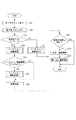
ここで、図8〜13を用いて、タッチ操作の検出動作について説明する。図8は、ユーザーのタッチ操作の検出動作のフローチャートである。この動作は、CPU64により実行する。
Here, the detection operation of the touch operation will be described with reference to FIGS. FIG. 8 is a flowchart of the detection operation of the user's touch operation. This operation is executed by the
まず、センサスキャンを動作させる(S31)。すなわち、静電センサパターンの静電容量を順次測定する。 First, the sensor scan is operated (S31). That is, the electrostatic capacitance of the electrostatic sensor pattern is sequentially measured.
次に、タッチ操作の有無の判定処理を行う(S32)本実施形態では、静電センサパターン毎に保存された後述するDIFF値を元に、タッチパネルの操作ありなしを判定処理を行うと共に、操作された座標の算出を行う。そして、S33においてタッチ操作の有無のフラグ=1の場合、すなわち、タッチ操作が検出された場合は、S34へ進む。タッチ操作の有無のフラグが1ではない場合、すなわち、タッチ操作が検出されない場合は、ベースライン更新処理2を実行し(S35)、S39へ進む。
Next, a process for determining the presence or absence of a touch operation is performed (S32). In the present embodiment, a process for determining whether or not the touch panel is operated is performed based on a DIFF value, which will be described later, stored for each electrostatic sensor pattern. The calculated coordinates are calculated. If the flag indicating whether or not a touch operation is performed in S33, that is, if a touch operation is detected, the process proceeds to S34. If the flag indicating the presence or absence of the touch operation is not 1, that is, if the touch operation is not detected, the
S34では、ベースライン更新判定処理を行う(S34)。ベースライン更新判定のフラグ=1の場合、ベースライン更新処理1を行い(S37)、S38へ進む。ベースライン更新判定のフラグが1ではない場合、そのままS38へ進む。
In S34, a baseline update determination process is performed (S34). When the baseline update determination flag = 1,
S38において、静電容量を元に操作位置の座標演算を行い、S39へ進む。なお、操作位置の座標は、各センサのDIFF値に基づいて算出する。 In S38, the coordinate calculation of the operation position is performed based on the capacitance, and the process proceeds to S39. The coordinates of the operation position are calculated based on the DIFF value of each sensor.
S39において、操作の有無の判定結果及び操作位置の座標計算結果に基づいて、前回の状態と同じか否かを判定する。前回の状態と同じである場合は、タッチ操作の検出処理を終了する。前回の状態と同じではない場合、すなわち、前回の操作状態及び座標データと比較して変化があった場合、操作状態及び座標データを更新してRAM65に保持する(S310)。その後、メイン制御部15に対して割込み信号を送出し(S311)、タッチ操作の検出処理を終了する。なお、図8に示すフローチャートの一連の動作は、約20MSECサイクルで繰り返し実行される。 In S39, it is determined whether or not it is the same as the previous state based on the determination result of the presence / absence of the operation and the coordinate calculation result of the operation position. If it is the same as the previous state, the touch operation detection process ends. If it is not the same as the previous state, that is, if there is a change compared to the previous operation state and coordinate data, the operation state and coordinate data are updated and stored in the RAM 65 (S310). Thereafter, an interrupt signal is sent to the main controller 15 (S311), and the touch operation detection process is terminated. Note that a series of operations in the flowchart shown in FIG. 8 is repeatedly executed in about 20 MSEC cycles.
ここで、S31のセンサスキャン動作について詳細に説明する。図9は、センサスキャン動作のフローチャートである。この処理は、CPU64により実行する。
Here, the sensor scan operation in S31 will be described in detail. FIG. 9 is a flowchart of the sensor scan operation. This process is executed by the
まず、センサ識別変数SENINDEXに初期値を設定する(S41)。次に、SENINDEXで指定された静電センサパターンの静電容量を計測する(S42)。 First, an initial value is set in the sensor identification variable SENINDEX (S41). Next, the electrostatic capacitance of the electrostatic sensor pattern designated by SENINDEX is measured (S42).
次に、静電容量の測定値(以下、RAW値とする)を保存(S43)すると共に、RAW値からベースライン値を引いた値(以下、DIFF値とする)をRAM65内に保存する(S44)。 Next, the measured capacitance value (hereinafter referred to as the RAW value) is saved (S43), and the value obtained by subtracting the baseline value from the RAW value (hereinafter referred to as the DIFF value) is saved in the RAM 65 (S43). S44).
DIFF値の保存が終了すると、過去のセンサスキャン動作時におけるDIFF値を保存しているデータ配列PREDIFF値を更新する(S45)。 When the storage of the DIFF value is completed, the data array PREDIFF value storing the DIFF value in the past sensor scan operation is updated (S45).
そして、次の静電センサパターンを特定するためにSENINDEXに1を加算する(S46)。 Then, 1 is added to SENINDEX in order to specify the next electrostatic sensor pattern (S46).
その後、センサ識別変数SENINDEXが18より大きいか判定し(S47)、18以下である場合は、S43に戻る。この動作を18本の静電センサパターンについて行うと処理を終了する(S47がYES)。 Thereafter, it is determined whether the sensor identification variable SENINDEX is larger than 18 (S47). If it is 18 or less, the process returns to S43. When this operation is performed for 18 electrostatic sensor patterns, the process is terminated (YES in S47).
また、図10を用いて、タッチパネルの操作の有無の判定について説明する。図10は、タッチパネル操作ありなし判定のフローチャートである。この処理は、CPU64により実行される。
In addition, with reference to FIG. 10, determination of presence / absence of touch panel operation will be described. FIG. 10 is a flowchart for determining whether or not there is a touch panel operation. This process is executed by the
操作の有無の判定は、1つのセンサペアを構成する上下2センサのDIFF値を合計し、所定数以上のセンサペアのDIFF値が、静電タッチIC12に予め設定されている操作閾値を超えたか否かにより行う。一般的な人体の指の大きさであるΦ9mmの指を想定した場合、本実施形態では、最低でも1センサペア以上のセンサペアに指が接触することになるため、1センサペア以上のセンサペアのDIFF値で操作閾値を超えた場合に操作ありと判定する。なお、操作の有無の判定の際の操作閾値を超えるセンサペア数は、これに限定されず、ターゲットとする操作対象及び被操作対象となる静電センサパターンに応じて設定すればよい。
Whether or not there is an operation is determined by summing the DIFF values of the upper and lower two sensors constituting one sensor pair, and whether or not the DIFF values of a predetermined number or more of the sensor pairs exceed the operation threshold set in advance in the
タッチパネルの操作の有無の判定をスタートさせると、まず、操作の有無を示すフラグと、操作閾値以上のセンサペア数と、センサペア識別変数を初期状態とする(S51)。なお、操作の有無を示すフラグは、タッチパネルを操作したと判定した場合に1となる。また、操作閾値以上のセンサペア数は、後述するペアDIFF値が操作閾値を超えているセンサペア数をカウントするための変数である。そして、センサペア識別変数は、本実施形態では、9ペアのセンサペアを識別するための変数である。したがって、S51では、操作の有無を示すフラグ=0、操作閾値以上のセンサペア数=0、センサペア識別変数PREINDEX=1とする。 When the determination of the presence / absence of the operation of the touch panel is started, first, a flag indicating the presence / absence of the operation, the number of sensor pairs equal to or greater than the operation threshold, and a sensor pair identification variable are set to an initial state (S51). The flag indicating the presence / absence of an operation is 1 when it is determined that the touch panel has been operated. The number of sensor pairs equal to or greater than the operation threshold is a variable for counting the number of sensor pairs whose pair DIFF value, which will be described later, exceeds the operation threshold. And a sensor pair identification variable is a variable for identifying 9 sensor pairs in this embodiment. Therefore, in S51, the flag indicating the presence / absence of operation = 0, the number of sensor pairs equal to or greater than the operation threshold = 0, and the sensor pair identification variable PREINDEX = 1.
次に、図9に示すフローチャートで保持されたDIFF値を、センサペア毎に足し合わせる(S52)。以下、センサペア毎に足し合わされた合計DIFF値を、ペアDIFF値とする。 Next, the DIFF values held in the flowchart shown in FIG. 9 are added for each sensor pair (S52). Hereinafter, the total DIFF value added for each sensor pair is referred to as a pair DIFF value.
次に、ペアDIFF値が操作閾値以上か判定を行う(S53)。操作閾値以上の場合(S53でYES)、操作閾値以上センサペア数に1を加算し(S54)、S55に進む。操作閾値未満である場合(S53でNO)、そのままS55に進む。 Next, it is determined whether the pair DIFF value is greater than or equal to the operation threshold (S53). If it is equal to or greater than the operation threshold (YES in S53), 1 is added to the number of sensor pairs equal to or greater than the operation threshold (S54), and the process proceeds to S55. If it is less than the operation threshold (NO in S53), the process proceeds to S55 as it is.
S55では、次の演算を行うセンサペアを特定するために、センサペア識別変数に1加算する。 In S55, 1 is added to the sensor pair identification variable in order to identify the sensor pair that performs the next calculation.
次に、センサペア識別変数が、センサ層の備えるセンサペアの数より大きいか判定する(S56)。本実施形態では、センサ層22には9センサペア存在しているので、センサペア識別変数が9より大きいか判定する。センサペア変数がセンサ層の備えるセンサペアの数より大きくない場合は、S52へ戻って処理を続ける。全センサペアに対して操作閾値以上かどうかの判定を終えると、S57へ進み、操作閾値以上のセンサペア数が1以上か判定する。
Next, it is determined whether the sensor pair identification variable is larger than the number of sensor pairs provided in the sensor layer (S56). In the present embodiment, since there are nine sensor pairs in the
ペアDIFF値が操作閾値以上のセンサペア数が1以上である場合(S57でYESの場合)、操作の有無を示すフラグ=1とし、タッチパネルの操作の有無の判定処理を終了し、ベースライン更新判定(S34)を行う。センサペア数が0である場合(S57でNOの場合)、タッチパネルの操作の有無の判定処理を終了し、環境変化等を反映するためのベースライン更新処理2を行う(S35)。
When the number of sensor pairs whose pair DIFF value is equal to or greater than the operation threshold is 1 or more (in the case of YES in S57), the flag indicating the presence / absence of operation is set to 1, and the determination process for the presence / absence of operation on the touch panel is terminated. (S34) is performed. If the number of sensor pairs is 0 (NO in S57), the touch panel operation determination process is terminated, and a
次に、図11を用いて、S34のベースライン更新判定処理について説明する。図11は、ベースライン更新判定処理のフローチャートである。この処理は、CPU64により実行される。
Next, the baseline update determination process in S34 will be described with reference to FIG. FIG. 11 is a flowchart of the baseline update determination process. This process is executed by the
まず、タイマカウンタがスタートしているのかどうかを判定する(S61)。 First, it is determined whether or not the timer counter has started (S61).
スタートしていない場合(S61でNOの場合)は、ベース更新判定フラグを初期設定として0にする(S62)。その後、最も静電容量が大きいセンサペア(以下、ピークセンサペアとする)を特定し、RAM65に保持(S63)し、タイマカウンタをスタートさせる(S64)。 If not started (NO in S61), the base update determination flag is set to 0 as an initial setting (S62). Thereafter, a sensor pair having the largest capacitance (hereinafter referred to as a peak sensor pair) is specified, held in the RAM 65 (S63), and a timer counter is started (S64).
すでにタイマカウンタがスタートしている場合(S61でYESの場合)は、ピークセンサが移動しているか否かの判定処理を行う(S65)。 If the timer counter has already been started (YES in S61), it is determined whether or not the peak sensor is moving (S65).
判定の結果、ピークセンサが移動している場合(S66でYESの場合)、タイマカウンタをクリアする(S67)。 If the result of determination is that the peak sensor is moving (YES in S66), the timer counter is cleared (S67).
ピークセンサが移動していない場合(S65でNOの場合)、タイマカウンタが所定時間以上であるか判定する(S68)。本実施形態では、上述した通り、タイマカウンタが5秒以上カウントされているかを判定する。タイマカウンタが5秒以上カウントされている場合(S68でYESの場合)、ベース更新フラグ=1とし(S69)、ベースライン更新判定処理を終了する。タイマカウンタが5秒未満である場合(S68でNOの場合)、ベースライン更新判定処理を終了する。 If the peak sensor is not moving (NO in S65), it is determined whether the timer counter is equal to or longer than a predetermined time (S68). In the present embodiment, as described above, it is determined whether the timer counter is counted for 5 seconds or more. If the timer counter has been counted for 5 seconds or more (YES in S68), the base update flag = 1 is set (S69), and the baseline update determination process is terminated. If the timer counter is less than 5 seconds (NO in S68), the baseline update determination process ends.
図12を用いて、S37のベースライン更新処理1について説明する。図12は、ベースライン更新処理1のフローチャートである。
The
まず、センサペア識別変数(PAREINDEX)に初期値を設定する(S71)。 First, an initial value is set in the sensor pair identification variable (PAREINDEX) (S71).
次に、PAREINDEXで指定されたセンサペアの10回前のセンサスキャン時のDIFF値(以下、ペアPREDIFF値とする)を算出する(S72)。具体的には、センサペアを構成する2センサのPREDIFF値を足し合わせることで、ペアPREDIFF値を算出する。
Next, the DIFF value (hereinafter referred to as the pair PREDIFF value) at the time of the
次に、ペアPREDIFF値と、今回のセンサスキャン動作時に算出されたペアDIFF値とを比較することで、静電容量の減少(DIFF値の減少)が更新判定閾値以上であったか否かを判定する(S73)。すなわち、所定時間内(本実施形態では、10回のセンサスキャンの間)の静電容量の減少が更新判定閾値以上であったか否かを判定する。本実施形態では、ペアPREDIFF値から今回のペアDIFF値を引いた値が、操作閾値以上か判定する。すなわち、本実施形態では、更新判定閾値は、操作閾値と同じ値とする。 Next, by comparing the pair PREDIFF value with the pair DIFF value calculated during the current sensor scan operation, it is determined whether or not the capacitance decrease (DIFF value decrease) is equal to or greater than the update determination threshold. (S73). That is, it is determined whether or not the decrease in capacitance within a predetermined time (in the present embodiment, during 10 sensor scans) is equal to or greater than the update determination threshold. In the present embodiment, it is determined whether the value obtained by subtracting the current pair DIFF value from the pair PREDIFF value is equal to or greater than the operation threshold. That is, in the present embodiment, the update determination threshold is the same value as the operation threshold.
判定の結果、更新判定閾値以上の減少があり(S73でYESの場合)、且つ、今回のセンサスキャン動作で算出されたペアDIFF値が操作閾値以上である場合(S74でYESの場合)は、ベースライン値を更新する(S75)。ベースライン値の更新は、センサペア識別変数PAREINDEXで指定されているセンサペアを構成する2つのセンサに対して、保持されているベースライン値を今回のセンサスキャン動作で保持されたRAW値とすることにより行う。すなわち、更新判定閾値以上の減少があり且つ今回のセンサスキャン動作で算出されたペアDIFF値が操作閾値以上である時点でのRAW値をベースライン値とする。判定の結果、更新判定閾値以上の減少がない場合(S73でNO)、又は更新判定閾値以上の減少があるが、ペアDIFF値が操作閾値未満である場合(S74でNO)、S76へ進む。 As a result of the determination, there is a decrease that is greater than or equal to the update determination threshold (in the case of YES in S73), and when the pair DIFF value calculated in the current sensor scan operation is equal to or greater than the operation threshold (in the case of YES in S74), The baseline value is updated (S75). The baseline value is updated by setting the retained baseline value to the RAW value retained in the current sensor scan operation for the two sensors constituting the sensor pair specified by the sensor pair identification variable PAREINDEX. Do. That is, the RAW value at the time when the pair DIFF value calculated by the current sensor scan operation is greater than or equal to the operation threshold is used as the baseline value. As a result of the determination, if there is no decrease greater than or equal to the update determination threshold (NO in S73), or there is a decrease greater than or equal to the update determination threshold but the pair DIFF value is less than the operation threshold (NO in S74), the process proceeds to S76.
S76で、センサペア識別変数PAREINDEXに1を加算し、S77で全てのセンサペアに処理を施したか判定する。本実施形態では、S77においてPAREINDEXが9より大きいか判定する。PAREINDEXが9以下である場合は、S72に戻って、処理を続ける。全てのセンサペアに処理を施したら、処理を終了する。 In S76, 1 is added to the sensor pair identification variable PAREINDEX, and it is determined in S77 whether all the sensor pairs have been processed. In this embodiment, it is determined whether PAREINDEX is greater than 9 in S77. If PAREINDEX is 9 or less, the process returns to S72 to continue the processing. When all the sensor pairs have been processed, the process ends.
本実施形態では、センサスキャン動作の周期が20msであり、ユーザーのリリース動作に対して非常に速いため、データ配列PREDIFF値の大きさを10として10回前のセンサスキャン時のセンサペアのDIFF値を算出した。すなわち、本実施形態では、200msの周期でセンサペアのDIFF値を算出するものとした。スキャン動作毎に静電容量値の差分を取る場合、すなわち、20ms周期で静電容量値の差分を取る場合、静電容量値の差分が非常に小さくなり、リリース操作による更新判定閾値を小さく設定しなければならなくなってしまう。そして、リリース操作による更新判定閾値を小さく設定した場合、ユーザーの指の接触面積のわずかな変化による静電容量の減少などに対応してベースライン値が更新されてしまい、タッチしているにも関わらず非タッチ判定がなされてしまう。そこで、本実施形態では、10スキャン毎に10スキャン前の静電容量値と測定された静電容量値とを比較し、更新判定閾値以上の減少を検出することで、ユーザーのリリース操作においてのみベースライン値の更新がなされるよう設定した。なお、更新判定の周期は、これに限定されず、リリース操作による更新判定を正確に判定することができるものであればよい。また、更新判定閾値は、例えば、Φ9mmの指に対して設定されているリリースによる静電容量の減少であることを確実に判定することができる値を設定すればよい。
In the present embodiment, the period of the sensor scan operation is 20 ms, which is very fast with respect to the user release operation. Therefore, the size of the data array PREDIFF value is 10, and the DIFF value of the sensor pair at the time of the
次に、図13を用いて、S35のベースライン更新処理2について説明する。図13は、ベースライン更新処理2のフローチャートである。
Next, the
ベースライン更新処理2は、タッチ操作によるタッチパネルの温度変化に基づく静電容量の上昇に対応させる更新処理ではなく、周囲環境に基づく静電容量の変化に対応させるための更新処理及び初期状態の設定を補正するための更新処理である。周囲環境に基づく静電容量の変化とは、例えば、タッチパネル11の環境温度等の緩やかな変化によるタッチパネルを操作していない場合の静電容量値の変化が挙げられる。なお、本実施形態では、各センサに対して環境閾値が設定されており、DIFF値が環境閾値と比較してどのような状態にあるのかを判定することで環境温度の変化に対応させる。また、初期状態の設定を補正するための更新処理とは、例えば、電源投入時にタッチパネルが操作された状態で計測された値がベースラインとなっている場合の補正を行うための更新処理である。
ベースライン更新処理2では、まず、センサ識別変数SENINDEXを初期値にセットする(S81)。
In the
次に、センサ識別変数SENINDEXによって指定されたセンサのDIFF値が、0より大きく環境閾値未満であるか否かを判定する(S82)。DIFF値が0を超えている場合、RAW値はベースライン値より大きい状態であり、DIFF値が0以下である場合、RAW値はベースライン値より小さい状態である。 Next, it is determined whether or not the DIFF value of the sensor designated by the sensor identification variable SENINDEX is greater than 0 and less than the environmental threshold (S82). When the DIFF value exceeds 0, the RAW value is larger than the baseline value, and when the DIFF value is 0 or less, the RAW value is smaller than the baseline value.
DIFF値が0より大きく、環境閾値未満である場合(S82でYES)、ベースライン値補正用のカウンタをクリア(S83)した後、ベースライン値に、所定値として、例えば、一定の値Αを加算しベースライン値を更新し(S84)、S813へ進む。これにより、次回の検出動作においては、更新されたベースライン値をもとにDIFF値が算出される。なお、S83のカウンタは、DIFF値が連続して環境閾値を下回っている回数を数えるカウンタである。 If the DIFF value is greater than 0 and less than the environmental threshold value (YES in S82), the baseline value correction counter is cleared (S83), and then the baseline value is set to a predetermined value, for example, a constant value Α. The baseline value is updated by addition (S84), and the process proceeds to S813. Thereby, in the next detection operation, the DIFF value is calculated based on the updated baseline value. The counter in S83 is a counter that counts the number of times that the DIFF value is continuously below the environmental threshold.
DIFF値が0以下である場合、DIFF値があらかじめ定めておいたベースライン変更閾値、本実施形態では、環境閾値にマイナスを乗算した値以上であるか否かを判定する(S85)。 When the DIFF value is 0 or less, it is determined whether or not the DIFF value is equal to or larger than a predetermined baseline change threshold value, in this embodiment, a value obtained by multiplying the environmental threshold value by minus (S85).
ベースライン変更閾値以上である場合、すなわち、環境閾値にマイナスを乗算した値以上である場合、ベースライン補正用カウンタをクリア(S86)したのち、現状のベースライン値に、所定値として、例えば、一定の値Αを減算して書き換える(S87)。その後S812へ進む。これにより、次回の検出動作においては、書き換えたベースライン値をもとにDIFF値が算出される。 If it is equal to or greater than the baseline change threshold, that is, equal to or greater than the value obtained by multiplying the environmental threshold by minus, after clearing the baseline correction counter (S86), the current baseline value is set as a predetermined value, for example, A constant value Α is subtracted and rewritten (S87). Thereafter, the process proceeds to S812. Thereby, in the next detection operation, the DIFF value is calculated based on the rewritten baseline value.
次に、DIFF値がベースライン変更閾値より小さいか判定する(S88)。DIFF値が環境閾値より小さい場合としては、キャリブレーション時にタッチパネルが操作されてしまっている状態が想定される。DIFF値が環境閾値より小さい場合(S88がYES)、ベースライン補正用カウンタに1をプラス(S89)した後、カウンタが20回以上かどうかを判定する(S810)。カウンタが20回以上だった場合(S810でYESの場合)、ベースライン値を現在のRAW値とする処理を行い(S811)、ベースライン補正用カウンタクリア(S812)する。これにより、次回の検出動作においては、書き換えたベースライン値をもとにDIFF値が算出される。DIFF値が環境閾値以上である場合(S88がNO)、ベースライン補正用カウンタをクリアする(S812)。 Next, it is determined whether the DIFF value is smaller than the baseline change threshold (S88). As a case where the DIFF value is smaller than the environmental threshold, it is assumed that the touch panel has been operated during calibration. If the DIFF value is smaller than the environmental threshold value (YES in S88), 1 is added to the baseline correction counter (S89), and then it is determined whether the counter is 20 times or more (S810). If the counter is 20 times or more (YES in S810), processing for setting the baseline value to the current RAW value is performed (S811), and the baseline correction counter is cleared (S812). Thereby, in the next detection operation, the DIFF value is calculated based on the rewritten baseline value. If the DIFF value is greater than or equal to the environmental threshold (S88 is NO), the baseline correction counter is cleared (S812).
その後、センサ識別変数SENINDEXに1加算(S813)して、全てのセンサペアの処理が行われたか判定する(S814)。本実施形態では、センサペア識別変数が9より大きいか判定する。全てのセンサペアの処理が終わっていない場合は、S82へ戻って処理を続ける。そして、全てのセンサペアの処理が行われた場合、すなわち、センサペア識別変数が9より大きい場合(S814がYES)、処理を終了する。 Thereafter, 1 is added to the sensor identification variable SENINDEX (S813), and it is determined whether all the sensor pairs have been processed (S814). In this embodiment, it is determined whether the sensor pair identification variable is greater than 9. If all sensor pairs have not been processed, the process returns to S82 and continues. If all sensor pairs have been processed, that is, if the sensor pair identification variable is greater than 9 (YES in S814), the process ends.
なお、本実施形態では、外来ノイズ等でRAW値の検出が影響を受けた場合を考慮して、S820のカウンタを20回としたが、S820のカウンタの数はこれに限定されず、状況に応じて設定可能である。 In this embodiment, considering the case where the detection of the RAW value is affected by external noise or the like, the counter of S820 is set to 20 times, but the number of counters of S820 is not limited to this, and the situation is not limited to this. It can be set accordingly.
本実施形態では、タッチパネルよりも温度の高い人間の指などによる操作によって引き起こされる静電容量の変化に応じて、基準値を変更(更新)することにより、誤動作やユーザーが操作できない状態を回避することができる。すなわち、タッチ操作前とタッチ操作後で無操作状態の静電容量が変化しても、タッチパネルの操作を正常に検知できない状態である不感帯を低減させることができる。すなわち、リリース操作及びリリース操作後のタッチ操作をより確実に判定することができる。これにより、タッチパネルの安定した操作を可能とすることができる。 (他の実施形態)
本発明の基本的構成は上述したものに限定されるものではない。上述した実施形態は、本発明の効果を得るための一手段であり、類似の別手法を用いたり、異なるパラメータを用いたとしても、本発明と同等の効果が得られる場合は、本発明の範疇に含まれる。
In this embodiment, a malfunction or a state in which the user cannot operate is avoided by changing (updating) the reference value in accordance with a change in capacitance caused by an operation with a human finger having a temperature higher than that of the touch panel be able to. That is, it is possible to reduce the dead zone in which the operation of the touch panel cannot be normally detected even if the capacitance in the non-operation state changes before and after the touch operation. That is, it is possible to more reliably determine the release operation and the touch operation after the release operation. Thereby, the stable operation of a touch panel can be enabled. (Other embodiments)
The basic configuration of the present invention is not limited to that described above. The above-described embodiment is a means for obtaining the effect of the present invention, and even if another similar method or a different parameter is used, if the same effect as the present invention can be obtained, the embodiment of the present invention can be obtained. Included in the category.
上述した実施形態では、静電容量値と基準値との差が操作閾値以上である場合にタッチ検出するものとしたが、これに限定されるものではない。例えば、静電容量値が所定の閾値以上であるか否かによりタッチ検出を判定するようにしてもよい。この場合は、基準値に所定の固定値を加算した値を「所定の閾値」として設定すればよい。 In the above-described embodiment, the touch detection is performed when the difference between the capacitance value and the reference value is greater than or equal to the operation threshold, but the present invention is not limited to this. For example, touch detection may be determined based on whether the capacitance value is equal to or greater than a predetermined threshold value. In this case, a value obtained by adding a predetermined fixed value to the reference value may be set as the “predetermined threshold value”.
上述した実施形態では、ベースライン更新処理2を行うものとしたが、ベースライン更新処理2は実行しなくてもよい。
In the above-described embodiment, the
上述した実施形態では、情報処理装置としてプリンタを例に挙げて説明したが、これに限定されるものではない。例えば、複写機、ファクシミリ装置、携帯電話、PDA、画像ビューワー、デジタルカメラ、などの静電タッチパネルを備える装置において、本発明を適用可能である。 In the above-described embodiment, a printer is described as an example of the information processing apparatus, but the present invention is not limited to this. For example, the present invention can be applied to an apparatus including an electrostatic touch panel such as a copying machine, a facsimile machine, a mobile phone, a PDA, an image viewer, and a digital camera.
上述した実施形態は、以下の処理を実行することによっても実現される。すなわち、上述した実施形態の機能を実現するソフトウェア(プログラム)を、ネットワーク又は各種記憶媒体を介してシステム或いは装置に供給し、そのシステム或いは装置のコンピュータ(CPUやMPU等)がプログラムを読み出して実行する処理である。また、プログラムは、1つのコンピュータで実行させても、複数のコンピュータを連動させて実行させるようにしてもよい。また、上記した処理の全てをソフトウェアで実現する必要はなく、一部又は全部をハードウェアによって実現するようにしてもよい。 The above-described embodiment can also be realized by executing the following processing. That is, software (program) that realizes the functions of the above-described embodiments is supplied to a system or apparatus via a network or various storage media, and a computer (CPU, MPU, etc.) of the system or apparatus reads and executes the program. It is processing to do. Further, the program may be executed by one computer or may be executed in conjunction with a plurality of computers. Further, it is not necessary to implement all of the above-described processing by software, and part or all of the processing may be realized by hardware.
11 静電容量方式のタッチパネル
12 静電タッチIC
13 LCD
14 LCDコントローラIC
15 メイン制御部
16 プリンタエンジン部
121 接続線
122 割り込み信号線
17 インターフェース部
21 カバーレンズ
22 センサ層
23 保護フィルム
24,25 接着シート
26 FPC
41 銅パターン
42 FPC
61 スイッチ
62 静電容量計測手段
63 ROM
64 CPU
65 RAM
66,67 信号線
11
13 LCD
14 LCD controller IC
DESCRIPTION OF
41
61
64 CPU
65 RAM
66, 67 signal line
Claims (17)
前記判定手段により前記静電タッチパネルが操作されていると判定されている期間において前記静電容量値の所定時間における減少量が第1閾値以上となった場合、前記基準値を大きくするように変更する変更手段と、
を備えることを特徴とするタッチパネルの制御装置。 And the capacitance value of the electrostatic sensor electrostatic touch panel is provided, and the reference value, based on a determination unit configured to determine whether the electrostatic touch panel is operated,
If reduction in a predetermined time of the electrostatic capacitance value in the period that has been determined with the electrostatic touch panel is operated becomes the first threshold value or more by the determination unit, modified to increase the reference value Change means to
A control device for a touch panel, comprising:
前記変更手段は、前記判定手段により前記静電タッチパネルが操作されていると判定され、前記カウント手段が所定時間以上をカウントし、前記静電容量値の所定時間における減少量が第1閾値以上である場合に更新を行うことを特徴とする請求項1〜14のいずれか1項に記載のタッチパネルの制御装置。 When it is determined by the determination means that the electrostatic touch panel is being operated, it further comprises a counting means for counting the operation time,
The changing means determines that the electrostatic touch panel is operated by the determining means, the counting means counts a predetermined time or more, and a decrease amount of the capacitance value in a predetermined time is equal to or more than a first threshold value. The touch panel control apparatus according to claim 1, wherein updating is performed in some cases.
前記静電タッチパネルが操作されていると判定されている期間において前記静電容量値の所定時間における減少量が第1閾値以上となった場合、前記基準値を大きくするように変更することを特徴とするタッチパネルの制御方法。 Based on the capacitance value in the electrostatic sensor provided in the electrostatic touch panel and the reference value , it is determined whether the electrostatic touch panel is operated,
If reduction in a predetermined time of the electrostatic capacitance value during a period in which the electrostatic touch panel is determined to be operated becomes the first threshold value or more, characterized in that to change so as to increase the reference value Touch panel control method.
静電タッチパネルが備える静電センサにおける静電容量値と、基準値と、に基づいて、静電タッチパネルが操作されているか否かを判定するステップと、A step of determining whether or not the electrostatic touch panel is operated based on a capacitance value in the electrostatic sensor included in the electrostatic touch panel and a reference value;
前記静電タッチパネルが操作されていると判定されている期間において前記静電容量値の所定時間における減少量が第1閾値以上となった場合、前記基準値を大きくするように変更するステップと、Changing the reference value to be larger when the amount of decrease in the capacitance value in a predetermined time is equal to or greater than a first threshold in a period in which it is determined that the electrostatic touch panel is being operated;
を実行させることを特徴とするプログラム。A program characterized by having executed.
Priority Applications (2)
| Application Number | Priority Date | Filing Date | Title |
|---|---|---|---|
| JP2013137061A JP6177026B2 (en) | 2013-06-28 | 2013-06-28 | Touch panel control device, touch panel control method, and program |
| US14/316,661 US10139964B2 (en) | 2013-06-28 | 2014-06-26 | Control apparatus for a touch panel and control method for the touch panel |
Applications Claiming Priority (1)
| Application Number | Priority Date | Filing Date | Title |
|---|---|---|---|
| JP2013137061A JP6177026B2 (en) | 2013-06-28 | 2013-06-28 | Touch panel control device, touch panel control method, and program |
Publications (3)
| Publication Number | Publication Date |
|---|---|
| JP2015011558A JP2015011558A (en) | 2015-01-19 |
| JP2015011558A5 JP2015011558A5 (en) | 2016-07-28 |
| JP6177026B2 true JP6177026B2 (en) | 2017-08-09 |
Family
ID=52115114
Family Applications (1)
| Application Number | Title | Priority Date | Filing Date |
|---|---|---|---|
| JP2013137061A Active JP6177026B2 (en) | 2013-06-28 | 2013-06-28 | Touch panel control device, touch panel control method, and program |
Country Status (2)
| Country | Link |
|---|---|
| US (1) | US10139964B2 (en) |
| JP (1) | JP6177026B2 (en) |
Cited By (1)
| Publication number | Priority date | Publication date | Assignee | Title |
|---|---|---|---|---|
| KR20210136096A (en) | 2019-05-22 | 2021-11-16 | 알프스 알파인 가부시키가이샤 | capacitive detection sensor |
Families Citing this family (26)
| Publication number | Priority date | Publication date | Assignee | Title |
|---|---|---|---|---|
| US9740343B2 (en) | 2012-04-13 | 2017-08-22 | Apple Inc. | Capacitive sensing array modulation |
| US9030440B2 (en) | 2012-05-18 | 2015-05-12 | Apple Inc. | Capacitive sensor packaging |
| US9883822B2 (en) | 2013-06-05 | 2018-02-06 | Apple Inc. | Biometric sensor chip having distributed sensor and control circuitry |
| US9984270B2 (en) | 2013-08-05 | 2018-05-29 | Apple Inc. | Fingerprint sensor in an electronic device |
| US10296773B2 (en) | 2013-09-09 | 2019-05-21 | Apple Inc. | Capacitive sensing array having electrical isolation |
| US9460332B1 (en) * | 2013-09-09 | 2016-10-04 | Apple Inc. | Capacitive fingerprint sensor including an electrostatic lens |
| US9697409B2 (en) | 2013-09-10 | 2017-07-04 | Apple Inc. | Biometric sensor stack structure |
| JP6284839B2 (en) * | 2014-06-26 | 2018-02-28 | 株式会社東海理化電機製作所 | Touch input device |
| EP3164685A4 (en) * | 2014-07-03 | 2017-08-23 | Auckland Uniservices Limited | External coupling sensor |
| JP6320256B2 (en) * | 2014-09-12 | 2018-05-09 | 三菱電機株式会社 | Electrostatic touch panel control device |
| JP2016075874A (en) * | 2014-10-09 | 2016-05-12 | 株式会社ジャパンディスプレイ | Liquid crystal display device |
| US9746961B2 (en) * | 2014-12-19 | 2017-08-29 | Apex Material Technology Corp. | Background signal processing system and background signal processing method |
| JP6416691B2 (en) * | 2015-05-14 | 2018-10-31 | アルプス電気株式会社 | Input device and operation method of input device |
| DE112015006572T5 (en) * | 2015-05-28 | 2018-03-15 | Mitsubishi Electric Corporation | Touch panel control device and vehicle information device |
| JP6629102B2 (en) * | 2016-03-01 | 2020-01-15 | アルプスアルパイン株式会社 | Input device, control method therefor, and program |
| JP6543590B2 (en) * | 2016-03-29 | 2019-07-10 | 株式会社東海理化電機製作所 | Input device |
| JP2018101281A (en) * | 2016-12-20 | 2018-06-28 | 株式会社東海理化電機製作所 | Touch detection device |
| CN109564481A (en) * | 2017-06-22 | 2019-04-02 | 深圳市汇顶科技股份有限公司 | Update method, device, touch screen and the electric terminal of touch screen present reference value |
| WO2019006667A1 (en) * | 2017-07-04 | 2019-01-10 | 深圳市汇顶科技股份有限公司 | Electronic device, touch detection circuit, and method for updating reference value of touchscreen |
| JP2019041968A (en) * | 2017-08-31 | 2019-03-22 | パナソニックIpマネジメント株式会社 | rice cooker |
| JP7120725B2 (en) * | 2018-11-14 | 2022-08-17 | アルパイン株式会社 | ELECTRONIC DEVICE WITH TOUCH PANEL, BASELINE VALUE UPDATE METHOD AND UPDATE PROGRAM |
| WO2020171607A1 (en) | 2019-02-19 | 2020-08-27 | 삼성전자 주식회사 | Touch circuit for preventing erroneous touch due to temperature change, electronic device comprising touch circuit, and method for operating same |
| CN111831144A (en) * | 2019-04-23 | 2020-10-27 | 北京小米移动软件有限公司 | Touch abnormity adjusting method and device |
| JP7196026B2 (en) * | 2019-06-28 | 2022-12-26 | 株式会社東海理化電機製作所 | Touch sensors, controllers, and computer programs |
| JP2022083296A (en) | 2020-11-24 | 2022-06-03 | シャープ株式会社 | Touch panel system, display device, and method for controlling touch panel system |
| JP2024003281A (en) * | 2022-06-27 | 2024-01-15 | アルプスアルパイン株式会社 | touch panel device |
Family Cites Families (19)
| Publication number | Priority date | Publication date | Assignee | Title |
|---|---|---|---|---|
| US5565658A (en) * | 1992-07-13 | 1996-10-15 | Cirque Corporation | Capacitance-based proximity with interference rejection apparatus and methods |
| KR970049359A (en) * | 1995-12-26 | 1997-07-29 | 베일리 웨인 피 | Method for detecting contact by relative speed of object with respect to sensing panel and device |
| JP2007208682A (en) | 2006-02-02 | 2007-08-16 | Matsushita Electric Ind Co Ltd | Touch panel |
| US7889176B2 (en) * | 2006-07-18 | 2011-02-15 | Avago Technologies General Ip (Singapore) Pte. Ltd. | Capacitive sensing in displacement type pointing devices |
| JP5055231B2 (en) * | 2008-09-08 | 2012-10-24 | 株式会社ジャパンディスプレイイースト | Touch position detection method for touch panel |
| KR101190276B1 (en) * | 2009-10-28 | 2012-10-12 | 주식회사 애트랩 | Input device and touch position detecting method thereof |
| TW201122980A (en) * | 2009-12-30 | 2011-07-01 | Novatek Microelectronics Corp | Method and apparatus for adjusting touch control parameter |
| US9164605B1 (en) * | 2010-02-03 | 2015-10-20 | Cypress Semiconductor Corporation | Force sensor baseline calibration |
| JP2011170617A (en) * | 2010-02-18 | 2011-09-01 | On Semiconductor Trading Ltd | Electrostatic capacity type touch sensor |
| CN102782623B (en) * | 2010-03-01 | 2015-12-02 | 松下知识产权经营株式会社 | Display device |
| JP5468438B2 (en) * | 2010-03-30 | 2014-04-09 | 株式会社ルネサスエスピードライバ | Touch discrimination device and data processing system |
| JP5618703B2 (en) * | 2010-08-25 | 2014-11-05 | 京セラ株式会社 | Mobile device |
| JP5839173B2 (en) * | 2010-10-14 | 2016-01-06 | Nltテクノロジー株式会社 | Touch sensor device and electronic device |
| JP5656666B2 (en) * | 2011-01-21 | 2015-01-21 | 三菱電機株式会社 | Touch panel device |
| JP2012216028A (en) * | 2011-03-31 | 2012-11-08 | Minebea Co Ltd | Input unit for electronic device and input method |
| KR101818663B1 (en) * | 2011-10-27 | 2018-01-17 | 삼성디스플레이 주식회사 | Touch detection system and driving method thereof |
| CN103677452B (en) * | 2012-08-30 | 2017-05-24 | 华为终端有限公司 | Capacitive touch screen calibration method and capacitive touch device |
| JP2014119931A (en) * | 2012-12-14 | 2014-06-30 | Fujitsu Ltd | Electronic apparatus and control program for touch sensor |
| KR101439855B1 (en) * | 2013-01-25 | 2014-09-17 | 주식회사 하이딥 | Touch screen controller and method for controlling thereof |
-
2013
- 2013-06-28 JP JP2013137061A patent/JP6177026B2/en active Active
-
2014
- 2014-06-26 US US14/316,661 patent/US10139964B2/en active Active
Cited By (3)
| Publication number | Priority date | Publication date | Assignee | Title |
|---|---|---|---|---|
| KR20210136096A (en) | 2019-05-22 | 2021-11-16 | 알프스 알파인 가부시키가이샤 | capacitive detection sensor |
| DE112020002442T5 (en) | 2019-05-22 | 2022-03-03 | Alps Alpine Co., Ltd. | Electrostatic capacity detection sensor |
| US11847281B2 (en) | 2019-05-22 | 2023-12-19 | Alps Alpine Co., Ltd. | Electrostatic-capacitance detection sensor |
Also Published As
| Publication number | Publication date |
|---|---|
| US10139964B2 (en) | 2018-11-27 |
| JP2015011558A (en) | 2015-01-19 |
| US20150002459A1 (en) | 2015-01-01 |
Similar Documents
| Publication | Publication Date | Title |
|---|---|---|
| JP6177026B2 (en) | Touch panel control device, touch panel control method, and program | |
| KR101642621B1 (en) | Touch-sensitive button with two levels | |
| JP5656666B2 (en) | Touch panel device | |
| EP2149838A2 (en) | Capacitive touch screen of a display device for detecting finger and stylus | |
| CN105786275B (en) | Electronic equipment and its control method | |
| US9459729B2 (en) | Sensing baseline management | |
| WO2015048114A1 (en) | Methods and apparatus for click detection on a force pad using dynamic thresholds | |
| JP5974745B2 (en) | Touch panel input device, touch input method, and touch input control program | |
| CN101957681A (en) | Can detect the touch-sensitive device and the method and system thereof of its ground connection situation | |
| TWI606376B (en) | Touch Sensor Device And Touch-Sensing Method With Error-Touch Rejection | |
| US20130278547A1 (en) | Electronic device | |
| CN108881657B (en) | Image forming apparatus, control method of image forming apparatus, and storage medium | |
| CN103616970A (en) | Touch response method and device | |
| US20140078536A1 (en) | Data processing apparatus and method for processing data | |
| CN105807955A (en) | Palm rejection visualization for passive stylus | |
| US20180284941A1 (en) | Information processing apparatus, information processing method, and program | |
| CN109642835B (en) | Finger thermal compensation full-bridge strain gauge array | |
| JP6660084B2 (en) | Touch panel device and image display method | |
| TWI602098B (en) | Touch Sensor Device And Sensing Method For Touch Point | |
| JP6308528B2 (en) | Capacitive input device | |
| KR102011766B1 (en) | Apparatus for displaying information using touch sensing signal and method thereof | |
| JP6973092B2 (en) | Touch panel and electronic devices | |
| CN106648217B (en) | Information processing apparatus and operation management method of touch screen | |
| US20240045550A1 (en) | Sensor panel and electronic equipment | |
| JP5425959B2 (en) | Jacket for touch panel structure |
Legal Events
| Date | Code | Title | Description |
|---|---|---|---|
| A521 | Written amendment |
Free format text: JAPANESE INTERMEDIATE CODE: A523 Effective date: 20160614 |
|
| A621 | Written request for application examination |
Free format text: JAPANESE INTERMEDIATE CODE: A621 Effective date: 20160614 |
|
| A977 | Report on retrieval |
Free format text: JAPANESE INTERMEDIATE CODE: A971007 Effective date: 20170309 |
|
| A131 | Notification of reasons for refusal |
Free format text: JAPANESE INTERMEDIATE CODE: A131 Effective date: 20170404 |
|
| A521 | Written amendment |
Free format text: JAPANESE INTERMEDIATE CODE: A523 Effective date: 20170602 |
|
| TRDD | Decision of grant or rejection written | ||
| A01 | Written decision to grant a patent or to grant a registration (utility model) |
Free format text: JAPANESE INTERMEDIATE CODE: A01 Effective date: 20170613 |
|
| A61 | First payment of annual fees (during grant procedure) |
Free format text: JAPANESE INTERMEDIATE CODE: A61 Effective date: 20170711 |
|
| R151 | Written notification of patent or utility model registration |
Ref document number: 6177026 Country of ref document: JP Free format text: JAPANESE INTERMEDIATE CODE: R151 |