JP6169850B2 - Portable information terminal and medical information provision system - Google Patents
Portable information terminal and medical information provision system Download PDFInfo
- Publication number
- JP6169850B2 JP6169850B2 JP2013008115A JP2013008115A JP6169850B2 JP 6169850 B2 JP6169850 B2 JP 6169850B2 JP 2013008115 A JP2013008115 A JP 2013008115A JP 2013008115 A JP2013008115 A JP 2013008115A JP 6169850 B2 JP6169850 B2 JP 6169850B2
- Authority
- JP
- Japan
- Prior art keywords
- information
- application
- information terminal
- portable information
- terminal
- Prior art date
- Legal status (The legal status is an assumption and is not a legal conclusion. Google has not performed a legal analysis and makes no representation as to the accuracy of the status listed.)
- Active
Links
Images


Landscapes
- Medical Treatment And Welfare Office Work (AREA)
Description
本発明の実施の形態は、携帯情報端末及び医療情報提供システムに関する。 Embodiments described herein relate generally to a portable information terminal and a medical information providing system.
近年、スマートフォン、タブレット型等の携帯情報端末の発達が著しい。当該携帯情報端末は、いずれの場所にも気軽に持ち運ぶことができることが最大のメリットで、先々で必要とする情報がすぐに入手できる。一方で、基本的にキーボードは附属せずタッチパネルのみによる操作をしなければならない等、インターフェイスが独特で細かい操作がし難い点がデメリットである。 In recent years, the development of mobile information terminals such as smartphones and tablets has been remarkable. The portable information terminal has the greatest advantage that it can be easily carried to any place, and the information necessary in advance can be obtained immediately. On the other hand, there is a demerit that the interface is unique and it is difficult to perform fine operations, such as a keyboard that is basically not attached and operations must be performed only with the touch panel.
また医療情報の領域では、X線CT装置(computed tomography:コンピュータ断層撮影装置)のような医用画像診断装置の発達、使用により、医療情報が多種多様、膨大な量になることも多い。このように多種多様、膨大な量にのぼる医療情報を医療現場で携帯情報端末によって取り扱う場合、それぞれ表示の対象となる医療情報に合わせて適切な表示アプリケーションを決定しなければならない。また、上記携帯情報端末を使用する場合には、この携帯情報端末の記憶領域の容量等との関係から、表示させるためには予めに医療情報を選択しておくことが必要となる等、表示させるための事前準備が必要となる場合も多く、上述した携帯情報端末のメリットを十分に生かすことができない。 Also, in the medical information area, medical information is often various and enormous in volume due to the development and use of medical image diagnostic apparatuses such as X-ray CT apparatuses (computed tomography). In this way, when handling a great variety of medical information with a portable information terminal at a medical site, it is necessary to determine an appropriate display application according to the medical information to be displayed. Also, when using the above-mentioned portable information terminal, it is necessary to select medical information in advance in order to display it from the relationship with the capacity of the storage area of this portable information terminal, etc. In many cases, advance preparation is required, and the above-described advantages of the portable information terminal cannot be fully utilized.
医療現場において携帯情報端末を使用する事例としては、以下の特許文献1に開示される発明が開示されている。
As an example of using a portable information terminal in a medical field, the invention disclosed in
しかしながら、上記特許文献1において開示されている発明では、次の点について配慮がなされていない。
However, the invention disclosed in
すなわち、上記特許文献1に記載の携帯(情報)端末は、あくまでもある特定の処置を行うために携帯されるものであり、扱う医療情報も病室によって表示させる患者のデータを変化させるものの、基本的には当該処置を行うに必要な情報に限定される。従って、当該携帯(情報)端末に汎用性はなく、当該処置を行うための機器に過ぎない。よしんば一般的な携帯情報端末を使用するとしても多種多様な医療情報をその場に応じて適宜に表示させることはできない。これでは一般的な携帯情報端末が持つ様々な機能、メリットを十分に生かすことができず、医療現場における使用に耐えない。
That is, the portable (information) terminal described in
本発明は上記課題を解決するためになされたものであり、本発明の目的は、使用される医療現場において最適な医療情報を表示させるべく適切なアプリケーションを適宜決定することによって、携帯情報端末の持つメリットを最大限生かしつつ膨大な医療情報を簡易ながらも十分に使用することで医療現場における作業効率の向上を図ることができる携帯情報端末及び医療情報提供システムを提供することにある。 The present invention has been made to solve the above-described problems, and an object of the present invention is to appropriately determine an appropriate application to display optimal medical information in a medical site to be used, thereby An object of the present invention is to provide a portable information terminal and a medical information providing system capable of improving work efficiency in a medical field by making full use of a great deal of medical information while making the best use of the merits of the medical care.
請求項1に記載の発明の特徴は、携帯情報端末において、携帯情報端末の位置を測定しその位置情報を取得する端末位置取得部と、携帯情報端末の位置情報と携帯情報端末を使用するユーザに関する情報とに基づいて、携帯情報端末の位置においてユーザが利用する可能性があるアプリケーションを決定し表示させる表示アプリ決定部と、表示されるアプリケーションのうちユーザが利用するために選択したアプリケーションを用いて表示させる対象を特定する表示データ決定部と、アプリケーションを用いて特定された対象を表示する表示部とを備え、表示データ決定部は、位置情報を基に患者を特定し、特定された患者に関する情報からアプリケーションを用いて表示させる対象を絞り込み特定する。
The feature of the invention described in
請求項5に記載の発明の特徴は、医療情報提供システムにおいて、携帯情報端末の位置を測定しその位置情報を取得する端末位置取得部と、携帯情報端末の位置情報と携帯情報端末を使用するユーザに関する情報とに基づいて、携帯情報端末の位置においてユーザが利用する可能性があるアプリケーションを決定し表示させる表示アプリ決定部と、表示されるアプリケーションのうちユーザが利用するために選択したアプリケーションを用いて表示させる対象を特定する表示データ決定部と、アプリケーションを用いて特定された対象を表示する表示部とを備え、表示データ決定部が、位置情報を基に患者を特定し、特定された患者に関する情報からアプリケーションを用いて表示させる対象を絞り込み特定する携帯情報端末と、携帯情報端末が備える表示データ決定部において表示の対象となるデータを記憶し、携帯情報端末の要求に応じて該当するデータを提供するデータベースとを備える。 According to a fifth aspect of the present invention, in the medical information providing system, the terminal position acquisition unit that measures the position of the portable information terminal and acquires the position information, the position information of the portable information terminal, and the portable information terminal are used. Based on information about the user, a display application determination unit that determines and displays an application that the user may use at the position of the portable information terminal, and an application selected for use by the user among the displayed applications A display data determination unit for specifying a target to be displayed and a display unit for displaying a target specified using an application , wherein the display data determination unit specifies a patient based on position information and is specified a portable information terminal that identifies refine object to be displayed using the application from the information on the patient, a portable information terminal Storing data to be displayed in the object in the display data decision unit comprises, and a database that provides the relevant data in response to a request of the mobile information terminal.
以下、本発明の実施の形態について図面を参照して詳細に説明する。 Hereinafter, embodiments of the present invention will be described in detail with reference to the drawings.
(第1の実施の形態)
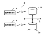
図1は、実施の形態における携帯情報端末1を含む医療情報提供システムSの全体構成を示すブロック図である。医療情報提供システムSは、携帯情報端末1と、携帯情報端末1において表示の対象となる医療情報を記憶し、携帯情報端末1の要求に応じて該当する医療情報を提供するデータベース2とから構成される。
(First embodiment)
FIG. 1 is a block diagram illustrating an overall configuration of a medical information providing system S including a
また、携帯情報端末1とデータベース2との間での医療情報のやり取りは、例えば、ブルートゥース(登録商標)等、無線を利用して行われる。一方、データベース2が複数設けられている場合には、これらは、例えば通信ネットワークNによって互いが接続されている。
In addition, the exchange of medical information between the
なお、医療情報提供システムSは、それ自体独立したシステムとして構成されても良いが、例えば、病院情報管理システム(HIS:Hospital Information System)、放射線部門情報管理システム(RIS:Radiological Information System)、医用画像管理システム(PACS:Picture Archiving Communication System)といった医療機関内に構築された各種管理システムの全て、或いは、その一部を構成するようにされていても良い。 The medical information providing system S may be configured as an independent system, for example, a hospital information management system (HIS), a radiation department information management system (RIS), a medical information system. All or a part of various management systems built in a medical institution such as a picture management system (PACS: Picture Archiving Communication System) may be configured.
携帯情報端末1は、可搬性があり、医師や技師等のユーザが医療行為や様々な処置、読影等の処理の際に使用する機器である。当該携帯情報端末1は、例えば、スマートフォンやタブレット等、その形態はどのようなものであっても良い。また、携帯情報端末1からデータベース2への医療情報の要求、或いは、データベース2から携帯情報端末1への医療情報の提供は、ここでは無線を利用して行われることを前提とする。但し、例えば、通信ネットワークNに携帯情報端末1を接続してデータベース2との間で医療情報のやり取りを行うことを排除するものではない。
The
データベース2は、医療機関内において発生する多種多様な医療情報を記憶する装置である。データベース2は、例えば、医療機関内に構築される、上述した様々な管理システムを構成しても良く、或いは、単独で設置されていても良い。さらには、クラウドシステムを利用して医療機関外に設けられていても良い。 The database 2 is a device that stores a wide variety of medical information generated in a medical institution. The database 2 may constitute, for example, the above-described various management systems constructed in a medical institution, or may be installed alone. Furthermore, it may be provided outside the medical institution using a cloud system.
通信ネットワークNは、データベース2をそれぞれつなぎ、互いの間で、例えば医用画像情報のやりとりを可能とする。なお、図1に示す医療情報提供システムSでは、通信ネットワークNに接続されているのは2つのデータベース2A、2Bのみでその図示を省略しているが、その他例えば、上述したX線CT装置等の医用画像診断装置(モダリティ)や会計システム等が接続されていても良い。
The communication network N connects the databases 2, and enables, for example, exchange of medical image information between each other. In the medical information providing system S shown in FIG. 1, only the two
通信ネットワークNの例としては、LAN(Local Area Network)やインターネット等のネットワークを挙げることができる。また、この通信ネットワークNで使用される通信規格は、DICOM(Digital Imaging and Communication in Medicine)等、いずれの規格であっても良い。 Examples of the communication network N include a network such as a LAN (Local Area Network) and the Internet. The communication standard used in the communication network N may be any standard such as DICOM (Digital Imaging and Communication in Medicine).
なお、図1に示す医療情報提供システムSでは、携帯情報端末1Aまたは1B(以下、適宜これら複数の携帯情報端末をまとめて「携帯情報端末1」と表わす。)が示され、通信ネットワークNに2つのデータベース2A及び2B(以下、適宜これら複数のデータベースをまとめて「データベース2」と表わす。)が接続されている。但し、携帯情報端末1の数、或いは、通信ネットワークNに接続されるデータベース2の数は単数、或いは複数のいずれでも良く、その数は任意である。
In the medical information providing system S shown in FIG. 1, the
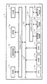
図2は、本発明の第1の実施の形態における携帯情報端末1の内部構成を示すブロック図である。携帯情報端末1は、CPU(Central Processing Unit)1aと、ROM(Read
Only Memory)1bと、RAM(Random Access Memory)1c及び入出力インターフェイス1dがバス1eを介して接続されている。入出力インターフェイス1dには、入力部1fと、表示部1gと、通信制御部1hと、記憶部1iとが接続されている。また、入出力インターフェイス1dには、端末位置取得部10と、表示アプリケーション決定部20と、表示データ決定部30とが接続されている。
FIG. 2 is a block diagram showing an internal configuration of the
A Only Memory (1b), a RAM (Random Access Memory) 1c, and an input /
CPU1aは、入力部1fからの入力信号に基づいてROM1bから携帯情報端末1を起動するためのブートプログラムを読み出して実行し、記憶部1iに格納されている各種オペレーティングシステムを読み出す。またCPU1aは、入力部1fや入出力インターフェイス1dを介して、図2において図示していないその他の外部機器からの入力信号に基づいて各種装置の制御を行う。さらにCPU1aは、RAM1cや記憶部1i等に記憶されたプログラム及びデータを読み出してRAM1cにロードするとともに、RAM1cから読み出されたプログラムのコマンドに基づいて、医療情報の表示のための処理やデータの計算、加工等、一連の処理を実現する処理装置である。
The
入力部1fは、携帯情報端末1のユーザ(例えば、医師や技師)が各種の操作を入力するタッチパネル等の入力デバイスにより構成されており、操作者の操作に基づいて入力信号を作成しバス1eを介してCPU1aに送信される。
The
表示部1gは、例えば液晶ディスプレイである。この表示部1gは、CPU1aからバス1eを介して出力信号を受信し、例えば、医療情報を表示するための複数のアプリケーションを表示させる等、或いはCPU1aの処理結果等を表示する。
The
通信制御部1hは、LANカードやモデム等の手段であり、携帯情報端末1を無線でインターネットやLAN等の通信ネットワークNに接続することを可能とする手段である。通信制御部1hを介してデータベース2との間で送受信した医療情報(データ)は入力信号または出力信号として、入出力インターフェイス1d及びバス1eを介してCPU1aに送受信される。
The
記憶部1iは、半導体や磁気ディスクで構成されており、CPU1aで実行されるプログラムやデータが記憶されている。また、携帯情報端末1から要求する医療情報をデータベース2から提供された際に、一旦当該医療情報を記憶させておく。さらに当該医療情報を表示するためのアプリケーションも記憶しておく。
The storage unit 1i is composed of a semiconductor or a magnetic disk, and stores programs and data executed by the
端末位置取得部10は、携帯情報端末1の位置を把握(取得)する。具体的に位置情報を取得する方法としては、例えば、GPS(Global Positioning System)を利用したり、或いは、RFID(Radio Frequency IDentification)を利用して、ユーザが当該携帯情報端末1をどの場所で使用するかを特定する。
The terminal
表示アプリケーション決定部20は、ユーザが必要とする医療情報を表示するために用いるアプリケーションを決定する。なお、以下において、或いは、図面においては、「表
示アプリケーション決定部20」を「表示アプリ決定部20」と表わす。
The display
表示データ決定部30は、携帯情報端末1を使用してユーザが表示する医療情報(データ)を決定、特定する。表示対象を携帯情報端末1の表示部1gに表示させるアプリケーションのみを決定しても、当該アプリケーションを起動させて表示させることができる医療情報は多岐に亘る可能性が高い。そこで、表示データ決定部30はより具体的にユーザが表示を欲する医療情報を絞り込む。
The display
なお、表示アプリ決定部20、及び、表示データ決定部30の詳しい機能、働きについては、以下、ユーザに対して医療情報を提供(表示)するまでの過程を説明する際に併せて説明する。
The detailed functions and functions of the display
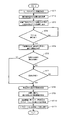
図3は、第1の実施の形態における医療情報の提供を行う流れを示すフローチャートである。ユーザから携帯情報端末1に必要な医療情報を表示させるに当たっては、まず、ユーザが当該携帯情報端末1にログインする必要がある。携帯情報端末1では、ユーザのログイン処理において入力された情報(以下、「ログイン情報」と表わす)を取得する(ST1)。
FIG. 3 is a flowchart illustrating a flow of providing medical information according to the first embodiment. In order to display necessary medical information on the
ここで「医療情報」には、患者自身の情報、患者のバイタル情報、或いは、患者に行われた処置やその結果、カルテに関する情報、撮影された医用画像等、医療機関内において取り扱われる様々な情報が含まれる。また、「ログイン情報」には、例えば、携帯情報端末1を使用するユーザのIDや医師、看護師、技師といった属性が含まれる。また、ログインされた日付け等の情報を含めても良く、さらには携帯情報端末1の位置情報も含めても構わない。このように、「医療情報」や「ログイン情報」にどのような情報を含めるかについては、任意に設定する事ができる。
Here, the “medical information” includes various information handled in the medical institution such as the patient's own information, the patient's vital information, the treatment performed on the patient and the result, the information about the medical record, the photographed medical image, etc. Contains information. Further, the “login information” includes, for example, attributes of a user who uses the
ログイン情報を取得すると、携帯情報端末1では、当該携帯情報端末1が存在する位置に関する情報(以下、適宜「位置情報」と表わす)を端末位置取得部10において取得する。なお、携帯情報端末1の位置情報については、適宜間隔を置いて端末位置取得部10において取得しても、或いは、リアルタイムに携帯情報端末1の位置を計測しても良い。以上で、携帯情報端末1を使用するユーザに関する情報、携帯情報端末1が存在する位置に関する情報が取得されたことになる。
When the login information is acquired, the
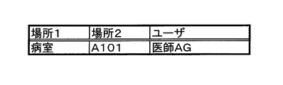
図4は、第1の実施の形態における携帯情報端末1の端末情報を示す一覧である。ここでは、携帯情報端末1の位置情報として「場所」の項目が設けられており、ユーザに関する情報として「ユーザ」の項目が設けられている。
FIG. 4 is a list showing terminal information of the
位置情報としての「場所」は、さらに2つの項目「場所1」及び「場所2」に分かれている。「場所1」は、例えば、「病室」や「検査室」、「手術室」といった大まかな位置が示されている。一方、「場所2」においては、さらに詳細な情報、例えば、「場所1」が「病室」である場合に、いずれの病室であるかを示す。図4に示す端末情報では、「病室」として「A101」が示されている。さらに、この携帯情報端末1を使用する「ユーザ」としては、「医師AG」が把握されている。
The “location” as the position information is further divided into two items “
そしてこれらの情報をまとめて、以下、「端末情報」と適宜表わす。なお、情報の項目としてどのような項目を設けるのかは自由である。また、1つの項目に属する項目の数をいくつ設けるかについては任意である。例えば、「場所」の項目について、さらに詳細な位置に関する情報として「場所3」というように特定することも可能である。この場合、携帯情報端末1の位置を位置情報として把握することが、患者の位置、すなわち患者を特定することにつながる。
These pieces of information are collectively expressed as “terminal information” as appropriate. In addition, what items are provided as information items is free. The number of items belonging to one item is arbitrary. For example, the item “place” may be specified as “
ここまでで携帯情報端末1は、上述したような端末情報を取得する。その上で、これら携帯情報端末1の位置情報及びログイン情報から、当該ユーザにおいて利用される可能性のあるアプリケーションを選択して表示させる(ST3)。これは、端末情報を用いて表示アプリ決定部20が表示部1gに表示させる。
Up to this point, the
例えば、端末情報から医師(読影医)が読影室にいることが把握できた場合には、読影に必要な医療情報である医用画像を表示させるために用いる画像ビューアのアプリケーションをユーザに対して提示する。或いは、端末情報から技師(理学療法士)がリハビリ室にいる場合に携帯情報端末1を使用する場合には、対象となる患者に対してリハビリの内容を説明するための説明資料を表示するべく、表示のためのアプリケーションとしてドキュメントビューアを提示する。
For example, if it can be determined from the terminal information that a doctor (interpretation doctor) is in the interpretation room, an image viewer application used to display a medical image that is medical information necessary for interpretation is presented to the user. To do. Alternatively, when the
ここでは図4において示したように、医師AGが病室(A101)にいることを前提に以下、さらに説明する。 Here, as shown in FIG. 4, the following description is further based on the assumption that the doctor AG is in the hospital room (A101).
表示アプリ決定部20は、端末情報を基にデータベース2にアクセスして、「場所」が「病室(A101)」であって、「ユーザ」が「医師(AG)」である情報をもってユーザに提示するアプリケーションについての情報の要求を行う。データベース2では、携帯情報端末1の表示アプリ決定部20からの要求に基づいて、当該位置においてユーザが表示するであろう医療情報(データ)及び該当する医療情報を表示するためのアプリケーションを表示アプリケーションデータテーブル内から取得する。
The display
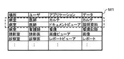
図5は、第1の実施の形態における表示アプリデータテーブルM1の一例を示す説明図である。表示アプリケーションデータテーブルM1には、例えば、「場所」、「ユーザ」、「アプリケーション」、「データ」の4つの項目が設けられている。例えば、携帯情報端末1からの要求が「診察室にいる診察医」に対して提示するアプリケーションの要求であれば、図5に示す表示アプリデータテーブルM1によればアプリケーションとしては「レポートビューア」を挙げることができる。なお、表示アプリデータテーブルM1に記憶させる項目については、上述した4つの項目に限られず、任意に設定することが可能である。
FIG. 5 is an explanatory diagram illustrating an example of the display application data table M1 according to the first embodiment. In the display application data table M1, for example, four items of “location”, “user”, “application”, and “data” are provided. For example, if the request from the
携帯情報端末1(表示アプリ決定部20)からの要求が、位置情報として「病室」、「ユーザ」として「医師」である場合には、図5に示す表示アプリデータテーブルM1において破線で囲む2つのアプリケーションが挙げられることになる。すなわち、「カルテ」のアプリケーションと「ドキュメントビューア」である。 When the request from the portable information terminal 1 (display application determining unit 20) is “patient” as the position information and “doctor” as the “user”, the display application data table M1 shown in FIG. One application will be mentioned. In other words, the application of “karte” and “document viewer”.
但し、この段階ではユーザが要求する医療情報をいずれのアプリケーションを利用して表示させるかは不明である。そこで、携帯情報端末1から送られてきた情報に基づいて検索することのできたアプリケーションである「カルテ」と「ドキュメントビューア」とを使用の可能性があるアプリケーションとしてこれらに関する情報を携帯情報端末1へと送り返す。
However, at this stage, it is unclear which application is used to display the medical information requested by the user. Therefore, information related to the “medical record” and the “document viewer” that can be searched based on the information sent from the
当該情報を受信した携帯情報端末1では、その表示部1gにユーザが利用する可能性のあるアプリケーションとしてデータベース2から受信した「カルテ」及び「ドキュメントビューア」の2つのアプリケーションを表示する(ST3)。
In the
図6は、第1の実施の形態における携帯情報端末1の表示部1gにおける表示例を示す説明図である。当該表示部1gにおいては、「現在地」として表示部1gの右上に現在携帯情報端末1が存在する位置が示されている。また、画面中央には、上段にユーザに対し
て提示されたアプリケーションの選択を促す文章「アプリケーションを選択して下さい。」が示されている。その下に表示アプリ決定部20が提示するアプリケーションである、「カルテ」と「ドキュメントビューア」とが表示されている。
FIG. 6 is an explanatory diagram illustrating a display example on the
すなわち、医師が病室にいる状態においては、医師は病室において、カルテを開く、或いは、患者に対して何らかの説明を行う、という状況が予想できる。そこで、携帯情報端末1の位置情報とユーザに関する情報とから、その場所においてその人が利用する可能性の高いアプリケーションを推測し、自動的に表示させる。
That is, in a state where the doctor is in the hospital room, a situation can be expected in which the doctor opens the chart or gives some explanation to the patient in the hospital room. Therefore, an application that is likely to be used by the person at the location is estimated from the position information of the
このように、携帯情報端末1の表示部1gには、端末情報を基にしたユーザが利用するであろうアプリケーションが単数、または、複数提示される。このことによって、ユーザは表示を求める医療情報を思い浮かべながら適宜自ら適切なアプリケーションを検索することなく、表示されたアプリケーションの中から適切なアプリケーションを決定するだけで医療情報を表示させるに適切なアプリケーションを決定することができる。
As described above, the
特に医用分野においては、X線CT画像の表示に最適なアプリケーション、或いは、心臓の表示に強みを持つアプリケーション、というように、アプリケーションごとに得意とする分野が固定される傾向が強い。このような状況の下では、ユーザ自身が医療情報を表示させる都度、適切なアプリケーションを選択し起動させる、というのは困難な場合もある。従って、携帯情報端末1の方で位置情報とユーザに関する情報から予めアプリケーションを見繕って提示してあげることで、ユーザがアプリケーションの選択に掛ける時間を短くすることができ、結果として作業効率の向上につながるものである。
In particular, in the medical field, there is a strong tendency that fields that are good for each application are fixed, such as an application that is optimal for displaying X-ray CT images or an application that has strength in displaying the heart. Under such circumstances, it may be difficult to select and activate an appropriate application each time the user himself / herself displays medical information. Therefore, the
ユーザはこのように、提示されたアプリケーションの中から自身が欲する医療情報の表示に適切なアプリケーションを選択し、決定する。携帯情報端末1では、当該選択の信号を受信したか否かを判断する(ST4)。図6に示す携帯情報端末1では、表示部1gにおいて表示されたアプリケーションのうち、「ドキュメントビューア」が選択された状態が示されている。この段階で、医師AGは、病室A101に入院している患者に対してドキュメントビューアを利用して何らかの文書(ここでは「説明資料」)を用いる(表示部1gに表示させる)ことを意図していることがわかる。
In this way, the user selects and determines an application appropriate for displaying the medical information he desires from among the presented applications. The
携帯情報端末1では、さらに、携帯情報端末1の位置情報からユーザ(医師)が対応しようとしている患者に関する情報を取得する(ST5)。なお、患者に関する情報を取得するためのデータテーブルは、データベース2内に記憶されていることから、携帯情報端末1の表示データ決定部30は、データベース2にアクセスして必要な情報を入手する。
The
図7は、第1の実施の形態における病室データテーブルOの一例を示す説明図である。病室データテーブルOには、「病室」に関する項目と「患者ID」に関する項目とが設けられている。当該病室データテーブルOによって、病室と当該病室に入院している患者とが紐付けられる。 FIG. 7 is an explanatory diagram illustrating an example of a hospital room data table O according to the first embodiment. In the hospital room data table O, an item related to “hospital room” and an item related to “patient ID” are provided. The patient room and the patient admitted to the patient room are linked by the patient room data table O.
図7に示す病室データテーブルOによると、ここで例に挙げている(携帯情報端末1が存在する)「病室A101」には、「001」と「002」との患者IDを持つ患者が入院していることがわかる。表示データ決定部30はこれら2人の患者の情報を取得する(ST6)。
According to the room data table O shown in FIG. 7, patients with patient IDs “001” and “002” are admitted to “hospital room A101” (the
但し、この段階では、まだ医師AGが病室A101に入院している「患者001」、或いは、「患者002」のいずれに対して説明資料を使用するのかが不明である。そこで、さらに、対象となる患者を特定する(ST7)。表示データ決定部30は、データベース2に対して患者を特定する情報の提供を要求する。ここでは、データベース2は検査デー
タテーブルPから患者を特定する情報を検索し、携帯情報端末1(表示データ決定部30)へと送信する。携帯情報端末1において受信した情報は、例えば記憶部1iに記憶される。
However, at this stage, it is unclear which of the “
図8は、第1の実施の形態における検査データテーブルPの一例を示す説明図である。当該検査データテーブルPに示されている通り、ここでは4つの項目「検査室」、「日付け」、「患者ID」、及び「検査」に分けて検査に関する情報が記憶されている。「検査室」としては、「CT01」と「XR01」に関する情報が記憶されている。 FIG. 8 is an explanatory diagram illustrating an example of the inspection data table P according to the first embodiment. As shown in the examination data table P, here, information related to examinations is stored in four items “examination room”, “date”, “patient ID”, and “examination”. As “inspection room”, information related to “CT01” and “XR01” is stored.
ここで「CT01」は、X線CT装置を利用した検査を行う第1検査室を示している。一方「XR01」は、X線撮影装置を利用した検査を行う第1検査室を示している。また、「日付け」は、検査が行われた、或いは、行われる予定の日付けである。「検査」は、患者に対して行われる、或いは、行われた検査の内容が示されている。 Here, “CT01” indicates a first examination room that conducts an examination using an X-ray CT apparatus. On the other hand, “XR01” indicates a first examination room that conducts an examination using an X-ray imaging apparatus. The “date” is a date on which the inspection is performed or scheduled to be performed. The “examination” indicates the contents of the examination that has been or has been performed on the patient.
上述した病室A101に入院している患者「001」或いは「002」のうち、当該検査データテーブルPに記載されている患者は、「001」である。すなわち、図8の破線に囲まれた欄に示されている通り、患者「001」は、検査室「CT01」において、「2012年5月1日」に「造影CT」という検査を受けることがわかる。 Of the patients “001” or “002” who are hospitalized in the above-described hospital room A101, the patient described in the examination data table P is “001”. That is, as shown in the column surrounded by the broken line in FIG. 8, the patient “001” may undergo an examination “contrast CT” on “May 1, 2012” in the examination room “CT01”. Recognize.
表示データ決定部30では、当該検査に関する情報をデータベース2から取得することで、医師AGが病室A101に入院しているどの患者に対してドキュメントビューアを利用使用としているのか、特定することができる。そして、当該患者に関する情報を確定させる(ST8)。
The display
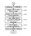
患者に関する情報が確定されると、対象となる検査についても特定される。さらに、当該特定された検査から実際にアプリケーションを利用して表示させる対象が特定される(ST9)。すなわち、表示データ決定部30では、対象となる患者に対して行われる検査に関する情報から、当該検査が行われる際に患者に対して示される(説明される)資料の特定が可能となる。そこで、表示データ決定部30は、データベース2に対して選択されたアプリケーションを利用して表示させる文献(資料)についての情報を要求する(ST10)。
Once the information about the patient is finalized, the target exam is also identified. Further, a target to be actually displayed using an application is specified from the specified examination (ST9). In other words, the display
データベース2では、当該要求を受信して、記憶している情報を検索する。図9は、第1の実施の形態における説明資料データテーブルQの一例を示す説明図である。説明資料データテーブルQには、「検査」と当該検査が行われる際に医師が患者に検査の説明をする際に用いる「説明資料」が紐付けられて記憶されている。 The database 2 receives the request and searches stored information. FIG. 9 is an explanatory diagram illustrating an example of the explanatory material data table Q according to the first embodiment. In the explanation material data table Q, “examination” and “explanation material” used when the doctor explains the examination to the patient when the examination is performed are linked and stored.
例えば、患者「001」が受ける予定にしている検査は「造影CT」の検査であり、患者「001」が当該検査を受ける場合には、「造影剤の副作用について」という説明資料を用いて事前に医師から説明を受ける。 For example, the examination that the patient “001” is scheduled to receive is the “contrast CT” examination, and when the patient “001” is to receive the examination, use the explanatory material “about the side effects of the contrast agent” in advance. Get an explanation from your doctor.
そこで、医師AGが病室A101に入院している患者「001」に対して検査を行う場合には、事前に説明を行う。この際には、携帯情報端末1を使用してドキュメントビューアを起動させ、表示部1gに造影剤の副作用について説明している説明資料を表示させながら説明を行う(ST11)。
Therefore, when the doctor AG performs an examination on the patient “001” who is hospitalized in the hospital room A101, a description will be given in advance. At this time, the document viewer is activated using the
このように、表示アプリ決定部20にてユーザが利用する可能性のあるアプリケーションを携帯情報端末の位置情報とユーザに関する情報とから特定するが、このままでは、当該特定されたアプリケーションを利用して表示される医療情報の限定、特定までには至らないことも多い。上述したように、近年医療情報の量は膨大となり、多様化していきてお
り、同じアプリケーションを利用して表示が可能となる医療情報は膨大な数にのぼるからである。そこで、表示データ決定部30は特定されたアプリケーションを利用する医療情報の中からさらに一層実際にユーザが表示を望んでいる医療情報を限定、特定する役割を果たす。
As described above, the display
以上説明したように、携帯情報端末の位置情報と当該携帯情報端末を使用するユーザに関する情報とから、ユーザが使用する可能性のあるアプリケーションを提示するとともに、選択されたアプリケーションを利用してユーザが必要とする医療情報を表示させる。従って、使用される医療現場において最適な医療情報を表示させるべく適切なアプリケーションを適宜決定することによって、携帯情報端末の持つメリットを最大限生かしつつ膨大な医療情報を簡易ながらも十分に使用することで医療現場における作業効率の向上を図ることができる携帯情報端末及び医療情報提供システムを提供することができる。 As described above, from the position information of the portable information terminal and the information related to the user who uses the portable information terminal, the application that the user may use is presented, and the user uses the selected application. Display the necessary medical information. Therefore, by appropriately determining the appropriate application to display the optimal medical information in the medical site to be used, it is possible to easily use the enormous amount of medical information while making the most of the merits of the portable information terminal. Therefore, it is possible to provide a portable information terminal and a medical information providing system capable of improving work efficiency in a medical field.
また、携帯情報端末の位置情報とユーザに関する情報とから利用される可能性の高いアプリケーションを提示するため、医療現場において必要とされる医療情報が遅滞なく表示されることになり、結果として処置や処方といった医療行為の効率化を図ることが可能となる。 In addition, in order to present an application that is highly likely to be used from the position information of the portable information terminal and information related to the user, medical information required in the medical field is displayed without delay. It becomes possible to improve the efficiency of medical practice such as prescription.
なお、以上においては医師が病室にいることを前提として様々説明を行ってきたが、当然携帯情報端末は病室のみで使用されるわけではなくその可搬性の良さもあり、検査室、処置室、読影室、リハビリ室、或いは、診察室というように様々な場所で使用される。従って位置情報やユーザに関する情報から利用するアプリケーションを検索して提示されるアプリケーションの種類は当然異なるが、ログイン情報の取得から必要とする医療情報の表示までの流れは、携帯情報端末をいずれの場所において使用しても変化しない。 In the above, various explanations have been made on the assumption that the doctor is in the hospital room, but naturally the portable information terminal is not used only in the hospital room and its portability is good, and the examination room, treatment room, It is used in various places such as reading rooms, rehabilitation rooms, or examination rooms. Accordingly, the types of applications presented by searching for applications to be used from location information and user-related information are naturally different, but the flow from acquisition of login information to display of necessary medical information depends on the location of the portable information terminal. It does not change even if used in.
(第2の実施の形態)
次に本発明における第2の実施の形態について説明する。なお、第2の実施の形態において、上述の第1の実施の形態において説明した構成要素と同一の構成要素には同一の符号を付し、同一の構成要素の説明は重複するので省略する。
(Second Embodiment)
Next, a second embodiment of the present invention will be described. In the second embodiment, the same components as those described in the first embodiment are denoted by the same reference numerals, and the description of the same components is omitted because it is duplicated.
携帯情報端末とデータベース2とによって医療情報提供システムSが構成されることは第1の実施の形態と同様である。但し、携帯情報端末の内部構成、及び、医療情報の提供を行う流れが相違する。 The medical information providing system S is configured by the portable information terminal and the database 2 as in the first embodiment. However, the internal configuration of the portable information terminal and the flow of providing medical information are different.
図10は、第2の実施の形態における携帯情報端末1Aの内部構成を示すブロック図である。携帯情報端末1Aの基本的な構成は第1の実施の形態における携帯情報端末1と同様であるが、新たに現在時刻取得部40が追加されている点に特徴がある。現在時刻取得部40は、ユーザが携帯情報端末1Aを使用するためにログインした際の日時を取得する機能を備えている。
FIG. 10 is a block diagram showing an internal configuration of the portable information terminal 1A in the second embodiment. The basic configuration of the portable information terminal 1A is the same as that of the
図11、及び、図12は、第2の実施の形態における医療情報の提供を行う流れを示すフローチャートである。携帯情報端末1Aを使用するユーザが携帯情報端末1Aにログインを行うとともに、ログイン情報を取得した携帯情報端末1Aが自機の位置情報を取得するステップは、これまで説明した通りである。 FIG. 11 and FIG. 12 are flowcharts showing the flow of providing medical information in the second embodiment. The steps in which the user using the portable information terminal 1A logs in to the portable information terminal 1A and the portable information terminal 1A that has acquired the login information acquires the position information of the own device are as described above.
その結果、携帯情報端末1Aが取得した端末情報は、次の通りである。図13は、第2の実施の形態における携帯情報端末1Aの端末情報を示す一覧である。ここで取得された端末情報としては、まず場所(位置情報)は、「病室 A101」である。ユーザは、「看護師XY」である。また、日付けは「2012年5月3日」となっている。 As a result, the terminal information acquired by the portable information terminal 1A is as follows. FIG. 13 is a list showing terminal information of the portable information terminal 1A according to the second embodiment. As the terminal information acquired here, first, the place (position information) is “patient A101”. The user is “nurse XY”. The date is “May 3, 2012”.
このような端末情報を取得し、携帯情報端末1Aは、看護師XYが表示させたい医療情報のために利用されるアプリケーションを提示するとともに、当該医療情報がいずれの患者に対する情報であるか特定するために、患者を特定する(ST3ないしST8)。ここまでは、第1の実施の形態において説明した通りである。なおここでは、看護師XYが担当する患者は、「A405病室」に入院している患者IDが「086」であるとする。 Obtaining such terminal information, the portable information terminal 1A presents an application used for medical information that the nurse XY wants to display, and specifies which patient the medical information is information about. Therefore, a patient is specified (ST3 to ST8). The steps so far are as described in the first embodiment. Here, it is assumed that the patient ID of the patient in charge of the nurse XY is “086” who is admitted to the “A405 hospital room”.
次に、特定された患者の情報から、当該患者に関するクリティカルパスを特定する(ST21)。ここで「クリティカルパス」とは、医師や看護師等からなるチームが、例えば特定の疾患等について共同で作業していく内容を時間軸に沿ってまとめた、いわば治療計画書である。 Next, a critical path related to the patient is identified from the identified patient information (ST21). Here, the “critical path” is a treatment plan document that summarizes the contents of a team of doctors, nurses, and the like working together on a specific disease, for example, along the time axis.
図14は、第2の実施の形態におけるクリティカルパスデータテーブルRの一例を示す説明図である。クリティカルパスデータテーブルRには、各患者に関するクリティカルパスが規定されている。すなわち、例えば、病室A405に入院している患者「086」については、「心臓カテーテル」についてのクリティカルパスである。 FIG. 14 is an explanatory diagram illustrating an example of the critical path data table R according to the second embodiment. The critical path data table R defines a critical path for each patient. That is, for example, the patient “086” who is hospitalized in the hospital room A405 is a critical path for the “cardiac catheter”.
さらに、現在時刻取得部40は、ログイン情報から時間情報を確認する(ST22)。看護師XYが携帯情報端末1Aにログインした日付けは、上述したように、「2012年5月3日」である。
Further, the current
なお、ここでの説明では、現在時刻取得部40は時間情報として時分までは確認していないが、時分まで確認するように設定されていても良い。特に患者の手術当日等、時間単位、分単位で患者が移動する、患者に対して処置しなければならないといった場合には、時分まで確認できるとより有効である。
In the description here, the current
現在時刻取得部40は、さらに、取得した時間情報を基に、イベント情報を確認する(ST23)。イベント情報は、イベントカレンダーデータテーブルに記憶されている。図15は、第2の実施の形態におけるイベントカレンダーデータテーブルTの一例を示す説明図である。イベントカレンダーデータテーブルTには、3つの項目が設けられており、それぞれ「患者ID」、「イベント」及び「予定日付け」である。図15においては、ここでの説明の対象として挙げている患者「086」の各イベントが分かるように示されている。ここでは患者「086」が2012年4月24日に入院してから、検査、手術を経て、2012年5月15日に退院するまでのイベントが示されている。
The current
現在時刻取得部40は、さらに、イベント情報の日付けのうち、時間情報による日付けより前で、直近の日付けを確認する(ST24)。これは、現在の患者「086」がどのような状態にあるのかを把握するための確認である。従って、上述したように時間情報から把握される時間(日付け)は、「2012年5月3日」である。一方、イベントカレンダーデータテーブルTにおけるイベントであって、「2012年5月3日」よりも前で直近の日付けは、「2012年5月1日」であり、この日に患者「086」は、手術を行っている。
The current
現在時刻取得部40は、時間情報による日付けと直近のイベントの日付けとを比較して経過日を算出する(ST25)。すなわち、イベントが行われた日から看護師XYがログインした日まで何日経過しているかを算出するものである。上述した例であれば、手術は「2012年5月1日」に行われ、時間情報が示す日付けは「2012年5月3日」であることから、「2012年5月3日」現在、手術というイベントから患者「086」は2日経過した状態にある、ということになる。
The current
さらに、表示データ決定部30がユーザ情報、位置情報、確認されたクリティカルパス
、及び算出された経過日を基に、表示アプリデータテーブルM2において該当する項目を抽出する(ST26)。ここで挙げている例では、看護師XYが「2012年5月3日」に病室A405においてログインし、看護師XYの医療行為の相手は患者「086」である。また、クリティカルパスは「心臓カテーテル」であって、イベントである手術からの経過日は2日である。
Further, the display
図16は、第2の実施の形態における表示アプリデータテーブルM2の一例を示す説明図である。ここでの「表示アプリデータテーブルM2」は、クリティカルパスに従って規定されている。 FIG. 16 is an explanatory diagram illustrating an example of the display application data table M2 according to the second embodiment. The “display application data table M2” here is defined according to the critical path.
当該表示アプリデータテーブルM2によれば、病室において看護師が心臓カテーテルを行った患者に対する場合については、2つの場合が考えられる。一方は起点となるイベントが「手術後」であって、経過日が「1〜3日」であるのに対し、他方は起点イベントは同じ「手術後」であるが、経過日は「10日〜15日」である。従って、看護師XYが手術後2日の患者「086」に携帯情報端末1Aを使用して対応する場合には、図16に矢印に示すように、提示されるアプリケーションは「看護」であり、表示されるデータ(医療情報)は、「点滴記録」となる。 According to the display application data table M2, there are two cases for a patient who has a cardiac catheter performed by a nurse in a hospital room. On the one hand, the starting event is “after surgery” and the elapsed date is “1-3 days”, while on the other, the starting event is the same “after surgery”, but the elapsed date is “10 days” ~ 15 days ". Therefore, when the nurse XY responds to the patient “086” on the second day after the operation using the portable information terminal 1A, as shown by the arrow in FIG. 16, the presented application is “nursing” The displayed data (medical information) is “drip recording”.
そこで、表示アプリデータテーブルM2から抽出された項目を基に表示対象となり得る医療情報を特定し(ここでは、「点滴記録」である)(ST27)、アプリケーション(看護)を起動して点滴記録を表示させる(ST11)。 Therefore, medical information that can be displayed based on the items extracted from the display application data table M2 is specified (here, “intravenous recording”) (ST27), and the application (nursing) is started to perform infusion recording. It is displayed (ST11).
以上説明したように、携帯情報端末の位置情報と当該携帯情報端末を使用するユーザに関する情報とから、ユーザが使用する可能性のあるアプリケーションを提示するとともに、選択されたアプリケーションを利用してユーザが必要とする医療情報を表示させる。 As described above, from the position information of the portable information terminal and the information related to the user who uses the portable information terminal, the application that the user may use is presented, and the user uses the selected application. Display the necessary medical information.
従って、使用される医療現場において最適な医療情報を表示させるべく適切なアプリケーションを適宜決定することによって、携帯情報端末の持つメリットを最大限生かしつつ膨大な医療情報を簡易ながらも十分に使用することで医療現場における作業効率の向上を図ることができる携帯情報端末及び医療情報提供システムを提供することができる。 Therefore, by appropriately determining the appropriate application to display the optimal medical information in the medical site to be used, it is possible to easily use the enormous amount of medical information while making the most of the merits of the portable information terminal. Therefore, it is possible to provide a portable information terminal and a medical information providing system capable of improving work efficiency in a medical field.
特に第2の実施の形態においては、表示データ決定部30における表示対象となる医療情報の絞り込みの際に時間情報をも利用することによって、よりきめ細かく表示対象となる医療情報を表示させるためのアプリケーションの提示をユーザに対して行うことが可能となる。時間情報は、クリティカルパスと親和性が高いと考えられることからクリティカルパスと絡めて利用する形態を説明したが、もちろん、第1の実施の形態においても時間情報を利用してユーザに対して提示するアプリケーションを選択することも可能である。
Particularly in the second embodiment, an application for displaying medical information to be displayed more finely by using time information when narrowing down medical information to be displayed in the display
(第3の実施の形態)
次に本発明における第3の実施の形態について説明する。なお、第3の実施の形態において、上述の第1、或いは第2の実施の形態において説明した構成要素と同一の構成要素には同一の符号を付し、同一の構成要素の説明は重複するので省略する。
(Third embodiment)
Next, a third embodiment of the present invention will be described. In the third embodiment, the same components as those described in the first or second embodiment are denoted by the same reference numerals, and the description of the same components is duplicated. I will omit it.
携帯情報端末とデータベース2とによって医療情報提供システムSが構成されることは第1の実施の形態と同様である。但し、携帯情報端末の内部構成、及び、医療情報の提供を行う流れが相違する。 The medical information providing system S is configured by the portable information terminal and the database 2 as in the first embodiment. However, the internal configuration of the portable information terminal and the flow of providing medical information are different.
図17は、第3の実施の形態における携帯情報端末1Bの内部構成を示すブロック図である。基本的な構成は、第1の実施の形態における携帯情報端末1と同様であるが、「アプリ間連携情報部50」が付加されている。
FIG. 17 is a block diagram showing the internal configuration of the
「アプリ間連携情報部50」は、ユーザに対して医療情報を表示させるに適切なアプリケーションを提示する際に、提示の対象となるアプリケーションのみならず、当該アプリケーションと連携するアプリケーションを検索して併せて提示する機能を備えている。
When presenting an appropriate application for displaying medical information to the user, the “inter-application
もともと携帯情報端末1Bはユーザに対してアプリケーションを提示する機能を備えているが、さらに当該アプリケーションと連携するアプリケーション(以下、適宜「連携アプリケーション」と表わす)を検索し、連携アプリケーションによって表示可能な医療情報も併せて表示させることによって、ユーザはもともと必要とする医療情報のみならず、当該医療情報に関連する医療情報をも表示させることができる。
The
図18は、第3の実施の形態における医療情報の提供を行う流れを示すフローチャートである。携帯情報端末1Bを使用するユーザが携帯情報端末1Bにログインを行うとともに、ログイン情報を取得した携帯情報端末1Bが自機の位置情報を取得するステップは、これまで説明した通りである(ST1及びST2)。
FIG. 18 is a flowchart illustrating a flow of providing medical information according to the third embodiment. The steps in which the user using the
その結果、携帯情報端末1Bが取得した端末情報は、次の通りである。図19は、第3の実施の形態における携帯情報端末1Bの端末情報を示す一覧である。ここで取得された端末情報としては、まず場所(位置情報)は、「読影室」である。なお、位置情報としては、「場所1」のみであり、「場所2」についての位置情報は設定がなく端末位置取得部10において取得されていない。もちろん、例えば読影室が複数ある場合には、「場所2」としてさらに詳細な位置情報に関する設定がなされていても良い。
As a result, the terminal information acquired by the
ユーザは、「読影医FN」である。また、日付けは「2012年4月27日」となっている。このような端末情報を取得し、携帯情報端末1Bは、読影医FNが表示させたい医療情報のために利用されるアプリケーションを提示する(ST3及びST4)。ここまでは、第1の実施の形態において説明した通りである。
The user is “interpretation doctor FN”. The date is “April 27, 2012”. Obtaining such terminal information, the
このようにユーザである読影医FNは、読影処理を行うに当たって、携帯情報端末1Bが提示したアプリケーションの中から適切なアプリケーションを選択する。携帯情報端末1Bでは、選択されたアプリケーションに関する情報を取得する。
As described above, the interpretation doctor FN who is the user selects an appropriate application from the applications presented by the
図20は、第3の実施の形態における表示アプリデータテーブルM3の一例を示す説明図である。携帯情報端末1Bが提示しユーザである読影医FNが選択したアプリケーションは、図20に破線で囲まれた「画像ビューア」である。これまでの実施の形態においては、アプリケーションとして例えば「画像ビューワ」が選択されたことを表示アプリ決定部20が確認すると、表示データ決定部30が当該選択されたアプリケーションを利用して表示する医療情報を絞り込む役割を果たしていた。
FIG. 20 is an explanatory diagram illustrating an example of the display application data table M3 according to the third embodiment. The application presented by the
第3の実施の形態においては、当該表示データ決定部30が表示対象となる医療情報の絞り込みの処理を行う前に、アプリ間連携情報部50が選択されたアプリケーションが表示する予定の医療情報に関連する医療情報(データ)があるか否かを検索する。すなわち、アプリ間連携情報部50は、選択されたアプリケーションによって表示される予定の医療情報に関連のある医療情報(以下、このような医療情報を適宜「連携データ」と表わす。)が連携データテーブル内に記憶されていないか、検索を行う(ST31)。
In the third embodiment, before the display
図21は、第3の実施の形態における連携データテーブルUの一例を示す説明図である。アプリ間連携情報部50は、データベース2にアクセスして連携データの検索要求をデータベース2に出す。データベース2では、ユーザによって選択されたアプリケーションによって表示される予定の医療情報に関連する連携データがあるか否か連携データテーブ
ルUを検索の上、結果をアプリ間連携情報部50へと送信する。
FIG. 21 is an explanatory diagram illustrating an example of the cooperation data table U according to the third embodiment. The inter-application
ここでは、ユーザである読影医FNによって「画像ビューア」がアプリケーションとして選択されている(図20参照)。従って、表示予定の医療情報は「画像」となる。アプリ間連携情報部50では当該選択された「画像ビューア」の情報を基に、さらに連携データの有無の検索をデータベース2に要求する。データベース2では、連携データテーブルU内を検索する。図21に示す連携データテーブルUをみると、「アプリケーション」という項目と「連携データ」の2つの項目が設けられている。
Here, the “image viewer” is selected as the application by the interpretation doctor FN who is the user (see FIG. 20). Therefore, the medical information scheduled to be displayed is an “image”. The inter-application
「アプリケーション」とは、ユーザが選択したアプリケーションを示している。一方「連携データ」は、選択されたアプリケーションにおいて表示予定の医療情報に関連する可能性のあるデータ(連携データ)を示している。連携データテーブルUによれば、「アプリケーション」として「画像ビューア」が選択されると、2つの「連携データ」が検索される。すなわち、「画像・レポート連携データ」及び「画像・カルテ連携データ」の2つの連携データである。このうち前者、「画像・レポート連携データ」からは、画像ビューワに連携するアプリケーションが「レポートビューア」であることが理解できる。一方、後者の「画像・カルテ連携データ」からは、画像ビューアに連携するアプリケーションが「カルテ」である。 “Application” indicates an application selected by the user. On the other hand, “cooperation data” indicates data (cooperation data) that may be related to the medical information scheduled to be displayed in the selected application. According to the linked data table U, when “image viewer” is selected as “application”, two “linked data” are searched. That is, there are two pieces of linkage data of “image / report linkage data” and “image / chart linkage data”. From the former, “image / report linkage data”, it can be understood that the application linked to the image viewer is “report viewer”. On the other hand, from the latter “image / chart linkage data”, the application linked to the image viewer is “karte”.
次にこれら把握される連携するアプリケーションを基に、連携データを検索する(ST32)。図22は、第3の実施の形態における使用データテーブルの一例を示す説明図である。使用データテーブルVによると、選択された画像ビューアに連携する連携データのうち、最近使用されたデータがアプリケーションごとに示されている。すなわち、項目として「アプリケーション」と「最近使用したデータ」の2つがあるが、「アプリケーション」とは、連携データテーブルUにおいて把握される、選択されたアプリケーションに連携するアプリケーションを示している。 Next, the cooperative data is searched based on the grasped cooperative applications (ST32). FIG. 22 is an explanatory diagram illustrating an example of a usage data table according to the third embodiment. According to the usage data table V, recently used data is shown for each application among the linkage data linked to the selected image viewer. That is, there are two items, “application” and “recently used data”, and “application” indicates an application linked to the selected application, which is grasped in the linked data table U.
上述した例に沿って言えば、「画像ビューア」に連携するアプリケーションである「カルテ」或いは、「レポートビューア」を利用して使用されたデータ(連携データ)がそれぞれ示されている。例えば、「カルテ」については、2種類のカルテ(カルテID「001」と「101」)が医療情報として使用、或いは、表示されている。また「レポートビューア」については、レポートID「00256」のレポートが作成、或いは表示等されている。 Speaking along the above-described example, “karte” that is an application linked to “image viewer” or data (linked data) used by using “report viewer” is shown. For example, regarding “medical chart”, two types of medical charts (medical chart IDs “001” and “101”) are used or displayed as medical information. As for “Report Viewer”, a report with a report ID “00256” is created or displayed.
さらに、データベース2では、最近使用されたデータを基に、当該連携データの詳細について検索する。連携するアプリケーションとしては、「カルテ」と「レポートビューア」とが把握され、それぞれのアプリケーションを利用して使用、表示等された医療情報もそれぞれ連携データとして把握される。そこで、アプリ間連携情報部50は、さらにデータベース2に対して把握された連携データの詳細を検索するよう、要求する。
Further, the database 2 searches for details of the linked data based on recently used data. As the applications to be linked, a “medical record” and a “report viewer” are grasped, and medical information used and displayed using the respective applications is also grasped as linkage data. Therefore, the inter-application
ここでは「レポートビューア」を例に挙げて説明する。図23は、第3の実施の形態におけるレポート状況データテーブルWの一例を示す説明図である。「レポートビューア」を利用して使用、表示等された連携データとして、使用データテーブルVからレポートID「00256」のレポートが把握されている。そこで、データベース2は、レポートが記憶されている、レポート状況データテーブルWを検索する。図23に示されているように、レポートIDが「00256」のレポートについては、「画像ID:I01256」という画像が用いられており、さらに「確定状況」として「未確定」とされている。 Here, “Report Viewer” will be described as an example. FIG. 23 is an explanatory diagram illustrating an example of the report status data table W according to the third embodiment. A report with a report ID “00256” is grasped from the usage data table V as linked data used, displayed, etc. using the “report viewer”. Therefore, the database 2 searches the report status data table W in which the report is stored. As shown in FIG. 23, for the report with the report ID “00256”, an image “image ID: I01256” is used, and the “confirmation status” is “unconfirmed”.
ここで「画像ID」とは、レポート内で使用されている画像のIDである。また、「確定状況」とは、読影医がレポートを作成する過程におけるレポートの内容の確定の有無を
示すものである。従って、未だ書き上げていない場合は「未確定」、レポートの作成が終了して今後当該レポートの内容に変更がない場合、ドラフトではない場合が「確定」となる。
Here, the “image ID” is an ID of an image used in the report. The “determined status” indicates whether or not the content of the report is confirmed in the process of the interpretation doctor creating the report. Therefore, “not determined” is written when the report has not yet been written, “fixed” when the report has been created and the contents of the report will not change in the future, and when the report is not drafted.
従って、ここで挙げた例に沿って説明すると、ユーザである読影医FNが選択した画像ビューアを利用して、例えば、レポートにおいて使用されている「画像ID:I01256」の画像を携帯情報端末1Bの表示部1gに表示させる(ST33)。併せて、連携するアプリケーションである「レポートビューア」を起動して、「レポートID:00256」のレポートをも表示させることができる。或いは、図を用いて説明していないが、連携するアプリケーションである「カルテ」を起動して、2種類のカルテ(カルテID「001」と「101」)のいずれかを表示させることも可能である。
Therefore, to explain along the example given here, using the image viewer selected by the image interpretation doctor FN as the user, for example, the image of “image ID: I01256” used in the report is displayed on the
以上説明したように、携帯情報端末の位置情報と当該携帯情報端末を使用するユーザに関する情報とから、ユーザが使用する可能性のあるアプリケーションを提示するとともに、選択されたアプリケーションを利用してユーザが必要とする医療情報を表示させる。 As described above, from the position information of the portable information terminal and the information related to the user who uses the portable information terminal, the application that the user may use is presented, and the user uses the selected application. Display the necessary medical information.
従って、使用される医療現場において最適な医療情報を表示させるべく適切なアプリケーションを適宜決定することによって、携帯情報端末の持つメリットを最大限生かしつつ膨大な医療情報を簡易ながらも十分に使用することで医療現場における作業効率の向上を図ることができる携帯情報端末及び医療情報提供システムを提供することができる。 Therefore, by appropriately determining the appropriate application to display the optimal medical information in the medical site to be used, it is possible to easily use the enormous amount of medical information while making the most of the merits of the portable information terminal. Therefore, it is possible to provide a portable information terminal and a medical information providing system capable of improving work efficiency in a medical field.
特に第3の実施の形態において説明した機能を利用することで、ユーザが選択したアプリケーションを利用して表示させる医療情報のみならず、当該アプリケーションに連携するアプリケーションを通して連携する医療情報までも表示させることが可能となる。 In particular, by using the function described in the third embodiment, not only the medical information to be displayed using the application selected by the user but also the medical information to be linked through the application linked to the application can be displayed. Is possible.
このようにユーザがそもそも希望する医療情報以外に関連する医療情報までも併せて表示させることが可能となるため、仮にユーザが思いつかなくとも基本となる医療情報のみ要求すれば、自動的に関連する医療情報まで表示されることになる。従って、医師等が活動を行う際に豊富な情報を自動的に把握することができ、患者に対して提供することができる医療情報が増えるとともに、作業効率の向上に一層資することになる。 In this way, since it is possible to display not only the medical information that the user originally desires but also related medical information, if the user requests only basic medical information even if it is not conceivable, it is automatically related. Medical information will be displayed. Therefore, abundant information can be automatically grasped when a doctor or the like performs an activity, medical information that can be provided to a patient is increased, and the work efficiency is further improved.
本発明の実施形態を説明したが、この実施形態は、例として提示したものであり、発明の範囲を限定することを意図していない。例えば、説明の都合上、3つの実施の形態に分けて説明しているが、これらを適宜自由に組み合わせて実施することも当然可能である。また、医療情報を表示させるアプリケーションについては、携帯情報端末の内部に備えていることを前提に説明を行ったが、データベース2内に記憶されていても、或いは、Webアプリのように医療情報提供システムの外に置かれていても良い。 Although an embodiment of the present invention has been described, this embodiment is presented as an example and is not intended to limit the scope of the invention. For example, for the convenience of explanation, the description is divided into three embodiments, but it is naturally possible to implement the embodiments by appropriately combining them. In addition, the application for displaying medical information has been described on the assumption that it is provided inside the portable information terminal. However, even if it is stored in the database 2 or is provided as a Web application It may be placed outside the system.
この実施形態は、その他の様々な形態で実施されることが可能であり、発明の要旨を逸脱しない範囲で、種々の省略、置き換え、変更を行うことができる。この実施形態やその変形は、発明の範囲や要旨に含まれると共に、特許請求の範囲に記載された発明とその均等の範囲に含まれる。 This embodiment can be implemented in various other forms, and various omissions, replacements, and changes can be made without departing from the spirit of the invention. This embodiment and its modifications are included in the scope and gist of the invention, and are included in the invention described in the claims and the equivalents thereof.
1 携帯情報端末
2 データベース
10 端末位置取得部
20 表示アプリ決定部
30 表示データ決定部
40 現在時刻取得部
50 アプリ間連携情報部
DESCRIPTION OF
Claims (5)
前記携帯情報端末の位置情報と前記携帯情報端末を使用するユーザに関する情報とに基づいて、前記携帯情報端末の位置において前記ユーザが利用する可能性があるアプリケーションを決定し表示させる表示アプリ決定部と、
前記表示されるアプリケーションのうち前記ユーザが利用するために選択したアプリケーションを用いて表示させる対象を特定する表示データ決定部と、
前記アプリケーションを用いて前記特定された対象を表示する表示部と、を備え、
前記表示データ決定部は、前記位置情報を基に患者を特定し、特定された前記患者に関する情報から前記アプリケーションを用いて表示させる対象を絞り込み特定することを特徴とする携帯情報端末。 A terminal position acquisition unit that measures the position of the portable information terminal and acquires the position information;
A display application determining unit that determines and displays an application that the user may use at the position of the portable information terminal based on the position information of the portable information terminal and information about the user who uses the portable information terminal; ,
A display data determination unit for specifying an object to be displayed using an application selected for use by the user among the displayed applications;
A display unit for displaying the identified object using the application ,
The portable data terminal characterized in that the display data determination unit specifies a patient based on the position information, and narrows down and specifies a target to be displayed using the application from information on the specified patient .
前記現在時刻取得部において取得された前記時間に関する情報と前記患者に対して行われるイベントに関する情報とに基づいて、前記表示データ決定部が前記表示部に表示させる対象を特定することを特徴とする請求項1に記載の携帯情報端末。 A current time acquisition unit for acquiring information about a time when the user uses the portable information terminal;
The display data determination unit specifies a target to be displayed on the display unit based on information on the time acquired by the current time acquisition unit and information on an event performed on the patient. The portable information terminal according to claim 1 .
前記表示データ決定部は、前記アプリ間連携情報部において抽出された前記アプリケーションに関連するアプリケーションによって表示される対象を特定することを特徴とする請求項1ないし請求項3のいずれかに記載の携帯情報端末。 An inter-application cooperation information unit that extracts an application related to the application selected by the user;
The display data decision unit, the mobile according to any one of claims 1 to claim 3, characterized in that identifying the object to be displayed by the application associated with the application that has been extracted in the application between the linkage information unit Information terminal.
前記携帯情報端末が備える表示データ決定部において表示の対象となるデータを記憶し、前記携帯情報端末の要求に応じて該当するデータを提供するデータベースと、
を備えていることを特徴とする医療情報提供システム。 A portable information terminal according to any one of claims 1 to 4 ,
A database that stores data to be displayed in a display data determination unit included in the portable information terminal, and provides corresponding data in response to a request from the portable information terminal;
A medical information providing system characterized by comprising:
Priority Applications (1)
| Application Number | Priority Date | Filing Date | Title |
|---|---|---|---|
| JP2013008115A JP6169850B2 (en) | 2013-01-21 | 2013-01-21 | Portable information terminal and medical information provision system |
Applications Claiming Priority (1)
| Application Number | Priority Date | Filing Date | Title |
|---|---|---|---|
| JP2013008115A JP6169850B2 (en) | 2013-01-21 | 2013-01-21 | Portable information terminal and medical information provision system |
Publications (2)
| Publication Number | Publication Date |
|---|---|
| JP2014139722A JP2014139722A (en) | 2014-07-31 |
| JP6169850B2 true JP6169850B2 (en) | 2017-07-26 |
Family
ID=51416410
Family Applications (1)
| Application Number | Title | Priority Date | Filing Date |
|---|---|---|---|
| JP2013008115A Active JP6169850B2 (en) | 2013-01-21 | 2013-01-21 | Portable information terminal and medical information provision system |
Country Status (1)
| Country | Link |
|---|---|
| JP (1) | JP6169850B2 (en) |
Families Citing this family (2)
| Publication number | Priority date | Publication date | Assignee | Title |
|---|---|---|---|---|
| CA2958322A1 (en) * | 2014-09-15 | 2016-03-24 | Qualcomm Life, Inc. | Capturing and managing healthcare information |
| KR20160097671A (en) | 2015-02-09 | 2016-08-18 | 삼성전자주식회사 | Mobile device for controlling medical apparatus and method for controlling medical apparatus thereof |
Family Cites Families (6)
| Publication number | Priority date | Publication date | Assignee | Title |
|---|---|---|---|---|
| JP2005293034A (en) * | 2004-03-31 | 2005-10-20 | Fuji Photo Film Co Ltd | Medical information management method, server and program |
| JP2007052699A (en) * | 2005-08-19 | 2007-03-01 | Toshiba Corp | Medical information processing system |
| JP5032274B2 (en) * | 2007-11-14 | 2012-09-26 | 株式会社東芝 | Portable information terminal authority management system and medical diagnostic apparatus equipped with the system |
| JP2011070324A (en) * | 2009-09-24 | 2011-04-07 | Toshiba Corp | Device and system for managing patient |
| JP5631322B2 (en) * | 2010-03-15 | 2014-11-26 | パナソニック株式会社 | Information processing terminal, confidential information access control method, program, recording medium, and integrated circuit |
| JP2013178681A (en) * | 2012-02-28 | 2013-09-09 | Sharp Corp | Application information presentation device, control method for application information presentation device, control program for application information presentation device, and computer readable recording medium recording the program |
-
2013
- 2013-01-21 JP JP2013008115A patent/JP6169850B2/en active Active
Also Published As
| Publication number | Publication date |
|---|---|
| JP2014139722A (en) | 2014-07-31 |
Similar Documents
| Publication | Publication Date | Title |
|---|---|---|
| US10777321B2 (en) | System and method for facilitating delivery of patient-care | |
| US9122773B2 (en) | Medical information display apparatus and operation method and program | |
| JP4959996B2 (en) | Interpretation report display device | |
| US20070168225A1 (en) | Workflow generator for medical-clinical facilities | |
| US10628986B1 (en) | Perioperative mobile communication system and method | |
| JP2014109835A (en) | Test result display device, operating method thereof, and control program | |
| JP2013239158A (en) | Medical information retrieval support device and medical information retrieval support system | |
| KR20070117166A (en) | Electonic medical record system | |
| JP6316546B2 (en) | Treatment plan formulation support device and treatment plan formulation support system | |
| JP2011204084A (en) | Examination implementation support program, examination implementation support device, examination implementation support system, and examination implementation support method | |
| JP5674719B2 (en) | Medical information processing apparatus and medical information program | |
| JP2012108761A (en) | Ordering system, radiological information management system equipped with the ordering system, and medical information management system | |
| JP6169850B2 (en) | Portable information terminal and medical information provision system | |
| JP2011128661A (en) | Regional medical cooperation system, registration terminal, and program | |
| KR102558521B1 (en) | Server for recommending solution based on user health information and mehtod thereof | |
| JP2019101678A (en) | Information processing apparatus, information processing method, information process system, and program | |
| JP2013148942A (en) | Radiation information management system, radiation information management method and radiation information management program | |
| KR20160086123A (en) | Apparatus for Electronic Medical Record Providing | |
| US20220270758A1 (en) | Medical information processing apparatus, medical information processing method, and non-transitory computer-readable medium | |
| JP2019101679A (en) | Information processing apparatus, information processing method, information process system, and program | |
| JP5662394B2 (en) | Medical support device and medical support method | |
| JP7181313B2 (en) | Medical support device | |
| JP7303605B1 (en) | program, method, information processing device, system | |
| JP6887921B2 (en) | Image search support device and team medical support system | |
| JP6584702B1 (en) | Medical support device, medical support method, and medical support program |
Legal Events
| Date | Code | Title | Description |
|---|---|---|---|
| RD01 | Notification of change of attorney |
Free format text: JAPANESE INTERMEDIATE CODE: A7421 Effective date: 20150703 |
|
| A621 | Written request for application examination |
Free format text: JAPANESE INTERMEDIATE CODE: A621 Effective date: 20151127 |
|
| A711 | Notification of change in applicant |
Free format text: JAPANESE INTERMEDIATE CODE: A711 Effective date: 20160527 |
|
| A977 | Report on retrieval |
Free format text: JAPANESE INTERMEDIATE CODE: A971007 Effective date: 20160819 |
|
| A131 | Notification of reasons for refusal |
Free format text: JAPANESE INTERMEDIATE CODE: A131 Effective date: 20160823 |
|
| A521 | Written amendment |
Free format text: JAPANESE INTERMEDIATE CODE: A523 Effective date: 20161021 |
|
| A02 | Decision of refusal |
Free format text: JAPANESE INTERMEDIATE CODE: A02 Effective date: 20170124 |
|
| A521 | Written amendment |
Free format text: JAPANESE INTERMEDIATE CODE: A523 Effective date: 20170417 |
|
| A911 | Transfer of reconsideration by examiner before appeal (zenchi) |
Free format text: JAPANESE INTERMEDIATE CODE: A911 Effective date: 20170425 |
|
| TRDD | Decision of grant or rejection written | ||
| A01 | Written decision to grant a patent or to grant a registration (utility model) |
Free format text: JAPANESE INTERMEDIATE CODE: A01 Effective date: 20170530 |
|
| A61 | First payment of annual fees (during grant procedure) |
Free format text: JAPANESE INTERMEDIATE CODE: A61 Effective date: 20170629 |
|
| R150 | Certificate of patent or registration of utility model |
Ref document number: 6169850 Country of ref document: JP Free format text: JAPANESE INTERMEDIATE CODE: R150 |
|
| S533 | Written request for registration of change of name |
Free format text: JAPANESE INTERMEDIATE CODE: R313533 |
|
| R350 | Written notification of registration of transfer |
Free format text: JAPANESE INTERMEDIATE CODE: R350 |