JP6168798B2 - Display device - Google Patents
Display device Download PDFInfo
- Publication number
- JP6168798B2 JP6168798B2 JP2013048589A JP2013048589A JP6168798B2 JP 6168798 B2 JP6168798 B2 JP 6168798B2 JP 2013048589 A JP2013048589 A JP 2013048589A JP 2013048589 A JP2013048589 A JP 2013048589A JP 6168798 B2 JP6168798 B2 JP 6168798B2
- Authority
- JP
- Japan
- Prior art keywords
- display device
- resin material
- housing
- glass
- protective plate
- Prior art date
- Legal status (The legal status is an assumption and is not a legal conclusion. Google has not performed a legal analysis and makes no representation as to the accuracy of the status listed.)
- Active
Links
Images


Classifications
-
- G—PHYSICS
- G02—OPTICS
- G02F—OPTICAL DEVICES OR ARRANGEMENTS FOR THE CONTROL OF LIGHT BY MODIFICATION OF THE OPTICAL PROPERTIES OF THE MEDIA OF THE ELEMENTS INVOLVED THEREIN; NON-LINEAR OPTICS; FREQUENCY-CHANGING OF LIGHT; OPTICAL LOGIC ELEMENTS; OPTICAL ANALOGUE/DIGITAL CONVERTERS
- G02F1/00—Devices or arrangements for the control of the intensity, colour, phase, polarisation or direction of light arriving from an independent light source, e.g. switching, gating or modulating; Non-linear optics
- G02F1/01—Devices or arrangements for the control of the intensity, colour, phase, polarisation or direction of light arriving from an independent light source, e.g. switching, gating or modulating; Non-linear optics for the control of the intensity, phase, polarisation or colour
- G02F1/13—Devices or arrangements for the control of the intensity, colour, phase, polarisation or direction of light arriving from an independent light source, e.g. switching, gating or modulating; Non-linear optics for the control of the intensity, phase, polarisation or colour based on liquid crystals, e.g. single liquid crystal display cells
- G02F1/133—Constructional arrangements; Operation of liquid crystal cells; Circuit arrangements
- G02F1/1333—Constructional arrangements; Manufacturing methods
- G02F1/133308—Support structures for LCD panels, e.g. frames or bezels
- G02F1/13332—Front frames
-
- G—PHYSICS
- G02—OPTICS
- G02F—OPTICAL DEVICES OR ARRANGEMENTS FOR THE CONTROL OF LIGHT BY MODIFICATION OF THE OPTICAL PROPERTIES OF THE MEDIA OF THE ELEMENTS INVOLVED THEREIN; NON-LINEAR OPTICS; FREQUENCY-CHANGING OF LIGHT; OPTICAL LOGIC ELEMENTS; OPTICAL ANALOGUE/DIGITAL CONVERTERS
- G02F1/00—Devices or arrangements for the control of the intensity, colour, phase, polarisation or direction of light arriving from an independent light source, e.g. switching, gating or modulating; Non-linear optics
- G02F1/01—Devices or arrangements for the control of the intensity, colour, phase, polarisation or direction of light arriving from an independent light source, e.g. switching, gating or modulating; Non-linear optics for the control of the intensity, phase, polarisation or colour
- G02F1/13—Devices or arrangements for the control of the intensity, colour, phase, polarisation or direction of light arriving from an independent light source, e.g. switching, gating or modulating; Non-linear optics for the control of the intensity, phase, polarisation or colour based on liquid crystals, e.g. single liquid crystal display cells
- G02F1/133—Constructional arrangements; Operation of liquid crystal cells; Circuit arrangements
- G02F1/1333—Constructional arrangements; Manufacturing methods
- G02F1/133308—Support structures for LCD panels, e.g. frames or bezels
- G02F1/133331—Cover glasses
Landscapes
- Physics & Mathematics (AREA)
- Nonlinear Science (AREA)
- Mathematical Physics (AREA)
- Chemical & Material Sciences (AREA)
- Crystallography & Structural Chemistry (AREA)
- General Physics & Mathematics (AREA)
- Optics & Photonics (AREA)
- Liquid Crystal (AREA)
- Devices For Indicating Variable Information By Combining Individual Elements (AREA)
Description
本発明は、保護板を備える表示装置に関する。 The present invention relates to a display device including a protective plate.
近年、液晶表示装置(Liquid Crystal Display:LCD)は、その軽量性、薄型性などの利点により、各種用途に広く使用されている。 2. Description of the Related Art In recent years, liquid crystal display devices (LCDs) have been widely used for various applications due to advantages such as light weight and thinness.
液晶表示装置に含まれる液晶表示パネルでは、配線および電極が形成されたガラス基板と、対向基板とが並行に配置される。また、当該液晶表示パネルでは、ガラス基板と対向基板との間に液晶が挟持されている。この液晶表示パネルの両面側には偏光板がそれぞれ貼り付けられている。液晶表示パネルの表示領域は、多数の画素から構成される。当該表示領域の各画素に表示画像に応じた信号が印加されることにより、画像が表示される。液晶表示パネルの背面に設置されたバックライトにより光が照射されことにより、当該表示画像が観察者に視認される。 In a liquid crystal display panel included in a liquid crystal display device, a glass substrate on which wirings and electrodes are formed and a counter substrate are arranged in parallel. In the liquid crystal display panel, liquid crystal is sandwiched between a glass substrate and a counter substrate. Polarizing plates are attached to both sides of the liquid crystal display panel. The display area of the liquid crystal display panel is composed of a large number of pixels. An image is displayed by applying a signal corresponding to the display image to each pixel in the display area. By irradiating light with a backlight installed on the back surface of the liquid crystal display panel, the display image is visually recognized by an observer.
このように、液晶表示装置は、画素ごとに光の透過率を制御する液晶表示パネルとバックライトとにより構成される。すなわち、液晶表示装置は、いわゆる受光型の表示装置であり、この特性を利用した種々の用途に使用されている。 As described above, the liquid crystal display device includes the liquid crystal display panel that controls the light transmittance for each pixel and the backlight. In other words, the liquid crystal display device is a so-called light receiving type display device, and is used for various applications utilizing this characteristic.
例えば、液晶表示装置は、パソコン用のディスプレイや、産業用途に使用される装置、車載の表示装置、ハンディ端末、広告表示機等として使用される。これら様々な環境で使用される液晶表示装置としての表示装置には、外部からの衝撃から、当該表示装置を保護する保護板を備える物が多数存在している。特許文献1では、保護カバー(保護板)を備える表示装置の構成が開示されている。 For example, the liquid crystal display device is used as a display for a personal computer, a device used for industrial use, an in-vehicle display device, a handy terminal, an advertisement display device, and the like. Many display devices as liquid crystal display devices used in these various environments include a protective plate that protects the display device from external impacts. In patent document 1, the structure of the display apparatus provided with a protective cover (protection board) is disclosed.
近年は、保護板を有する液晶表示装置においても、当該液晶表示装置の薄型化の要求が強い。そのため、保護板と筐体ケースとを固定する構造として、保護板を当該保護板の前面側から枠ケースで押さえ保持する構造(以下、構造Aともいう)がある。しかしながら、この構造Aは、液晶表示装置が厚くなるため、当該液晶表示装置に使用できない場合が多い。 In recent years, there is a strong demand for thinning of a liquid crystal display device having a protective plate. Therefore, as a structure for fixing the protective plate and the housing case, there is a structure in which the protective plate is pressed and held by the frame case from the front side of the protective plate (hereinafter also referred to as structure A). However, this structure A often cannot be used in the liquid crystal display device because the liquid crystal display device becomes thick.
また、保護板を構成する部材は、ガラス材が好まれる。当該ガラス材は、表面硬度が高い、傷つき難い、質感が高いという特徴を有する。保護板がガラス材で構成された状態において、もしも、ガラス材が破損した場合、安全性の観点から、ガラスの飛散を防止する事が望まれる。また、さらに、ガラスが破損した場合、破損したガラス(保護板)を容易に交換可能である事が望まれる。 Further, a glass material is preferred as a member constituting the protective plate. The glass material is characterized by high surface hardness, hardly scratches, and high texture. In a state where the protective plate is made of a glass material, if the glass material is broken, it is desired to prevent the glass from scattering from the viewpoint of safety. Further, when the glass is broken, it is desired that the broken glass (protection plate) can be easily replaced.
本発明は、このような問題を解決するためになされたものであり、ガラスを利用した保護板の破損時における、安全性の確保とメンテナンスの容易性とを両立することが可能な表示装置を提供することを目的とする。 The present invention has been made to solve such problems, and a display device capable of ensuring both safety and ease of maintenance when a protective plate using glass is broken. The purpose is to provide.
上記目的を達成するために、本発明の一態様に係る表示装置は、映像を表示する表示面を有する液晶表示装置と、前記液晶表示装置を収容する筐体と、前記表示面を覆う保護板と、を備え、前記保護板は、ガラスと、前記ガラスに貼り付けられる樹脂材とを含み、前記保護板の前記樹脂材は、前記筐体に着脱可能に固定され、前記筐体と前記樹脂材との間には隙間が設けられ、前記表示装置は、さらに、前記隙間を埋めるパッキンを備え、前記パッキンは、前記液晶表示装置の側面全体を囲むように設けられ、前記パッキンは、前記表示面と直交する方向において、前記樹脂材と前記筐体との間に設けられる。
In order to achieve the above object, a display device according to one embodiment of the present invention includes a liquid crystal display device having a display surface for displaying an image, a housing that houses the liquid crystal display device, and a protective plate that covers the display surface The protective plate includes glass and a resin material attached to the glass, and the resin material of the protective plate is detachably fixed to the housing, and the housing and the resin The display device further includes a packing that fills the clearance, the packing is provided so as to surround the entire side surface of the liquid crystal display device, and the packing includes the display. It is provided between the resin material and the housing in a direction perpendicular to the surface .
本発明によれば、ガラスに樹脂材が貼り付けられる。これにより、当該ガラスが破損した場合でも、ガラスの飛散を防止することができる。そのため、安全性を確保することができる。また、前記保護板の前記樹脂材は、前記筐体に着脱可能に固定される。そのため、保護板のガラスが破損した場合における当該保護板の交換を容易に行うことができる。したがって、表示装置は、ガラスを利用した保護板の破損時におけるメンテナンスの容易性、すなわち、高いメンテナンス性を有する。 According to the present invention, the resin material is attached to the glass. Thereby, even if the said glass is damaged, scattering of glass can be prevented. Therefore, safety can be ensured. The resin material of the protection plate is detachably fixed to the housing. Therefore, the protection plate can be easily replaced when the glass of the protection plate is broken. Therefore, the display device has ease of maintenance when the protective plate using glass is broken, that is, high maintainability.
これにより、ガラスを利用した保護板の破損時における、安全性の確保とメンテナンスの容易性とを両立することができる。 Thereby, it is possible to achieve both safety and ease of maintenance when the protective plate using glass is broken.
以下、図面を参照しつつ、本発明の実施の形態について説明する。以下の説明では、同一の構成要素には同一の符号を付してある。それらの名称および機能も同じである。したがって、それらについての詳細な説明を省略する場合がある。 Hereinafter, embodiments of the present invention will be described with reference to the drawings. In the following description, the same components are denoted by the same reference numerals. Their names and functions are also the same. Therefore, detailed description thereof may be omitted.
なお、実施の形態において例示される各構成要素の寸法、材質、形状、それらの相対配置などは、本発明が適用される装置の構成や各種条件により適宜変更されるものであり、本発明はそれらの例示に限定されるものではない。また、各図における各構成要素の寸法は、実際の寸法と異なる場合がある。 It should be noted that the dimensions, materials, shapes, relative arrangements, and the like of the constituent elements exemplified in the embodiments are appropriately changed depending on the configuration of the apparatus to which the present invention is applied and various conditions. It is not limited to those examples. Moreover, the dimension of each component in each figure may differ from an actual dimension.
<実施の形態1>
図1は、本発明の実施の形態1に係る表示装置100の概略構成を示す分解斜視図である。図2は、本発明の実施の形態1に係る表示装置100の断面図である。
<Embodiment 1>
FIG. 1 is an exploded perspective view showing a schematic configuration of a
図1および図2を参照して、表示装置100は、保護板1と、液晶表示装置7と、筐体8と、ネジ9とを備える。
With reference to FIGS. 1 and 2, the
保護板1は、ガラス2と、樹脂材4とを含む。ガラス2の形状は、板状である。ガラス2は、主面2aと、裏面2bとを有する。裏面2bは、主面2aの反対側の面である。保護板1の主面は、ガラス2の主面2aである。
The protection plate 1 includes
樹脂材4は、ポリカーボネイト、ポリエステル、アクリル、ABSなどの透明の樹脂で構成される。樹脂材4は、板状部4aと、棒状部4bとを有する。板状部4aの形状は、板状である。樹脂材4の板状部4aは、透明な接着材3により、ガラス2の裏面2bに貼り付けられる。すなわち、樹脂材4は、ガラス2に貼り付けられる。これにより、保護板1が構成される。
The
つまり、保護板1の主面(表面)側には、ガラス2が設けられる。保護板1の裏面側には、樹脂材4が設けられる。樹脂材4は、液晶表示装置7を保持する形状を有する保持形状部である。
That is, the
液晶表示装置7は、映像を表示する表示面6(画面)を有する。保護板1は、該保護板1の裏面2bが、液晶表示装置7の表示面6と対向するように配置される。すなわち、保護板1は、液晶表示装置7の表示面6を覆うように設けられる。これにより、保護板1の樹脂材4は、液晶表示装置7を保持する。
The liquid
保護板1と、液晶表示装置7との間には、空間(以下、空間Aともいう)が形成される。空間Aには、透光性を有する接着材5が充填される。これにより、保護板1は、液晶表示装置7に固定される。なお、空間Aには、接着材5が充填されなくてもよい。
A space (hereinafter also referred to as space A) is formed between the protective plate 1 and the liquid
なお、ガラス2は、液晶表示装置7の表示面6に対応するタッチパネルとして機能するように構成されてもよい。
The
筐体8は、液晶表示装置7および保護板1を収容する。筐体8の底面8aには、穴H1が設けられる。
The
保護板1の樹脂材4は、筐体8に着脱可能に固定される。少し具体的には、保護板1の樹脂材4は、ネジ9の締付け力により、筐体8に固定される。より具体的には、樹脂材4の棒状部4bには、筐体8の穴H1を貫通するネジ9が挿入される。すなわち、棒状部4bには、筐体8を介してネジ9が挿入される。これにより、棒状部4bは、ネジ9を固定する。つまり、棒状部4bは、ネジ9を固定するネジ固定部である。なお、ネジ9を棒状部4bからはずすことにより、保護板1を、筐体8から分離することができる。
The
以上説明したように、本実施の形態では、ガラス2に樹脂材4が貼り付けられる。これにより、当該ガラス2が破損した場合でも、ガラスの飛散を防止することができる。そのため、安全性を確保することができる。また、保護板1の樹脂材4は、筐体8に着脱可能に固定される。そのため、保護板1のガラス2が破損した場合における当該保護板1の交換を容易に行うことができる。したがって、表示装置100は、ガラスを利用した保護板の破損時におけるメンテナンスの容易性、すなわち、高いメンテナンス性を有する。
As described above, in the present embodiment, the
これにより、ガラスを利用した保護板の破損時における、安全性の確保とメンテナンスの容易性とを両立することができる。 Thereby, it is possible to achieve both safety and ease of maintenance when the protective plate using glass is broken.
また、樹脂材4は、ガラス2に貼り付けられる。これにより、質感の高いガラスを表面側に設けた保護板1に、ガラスの飛散を防止する機能を持たせることができる。
The
また、本実施の形態では、保護板1の樹脂材4は、ネジ9の締付け力により、筐体8に固定される。これにより、保護板1を筐体8に強固に固定することができる。
In the present embodiment, the
また、前述したように、ガラス2に樹脂材4が貼り付けられる。これにより、仮に、ガラス2の表面に強い衝撃が加わり、ガラス2が破損した場合でも、ガラスが飛散することを防止することができる。また、この場合、破損したガラスは、筐体8内にとどまる。これにより、高い安全性を確保できる。
Further, as described above, the
また、上記構成により、表示装置の厚みを増やすことなく、保護板1(樹脂材4)を筐体8に強固に固定することができるとともに、保護板1の交換(修理)が容易な表示装置を提供することができる。
Further, with the above configuration, the protective plate 1 (resin material 4) can be firmly fixed to the
<実施の形態1の変形例>
なお、保護板を樹脂材に固定する構造は、ネジを利用した構造に限定されない。保護板を樹脂材に固定する構造を、以下の構造としてもよい。
<Modification of Embodiment 1>
The structure for fixing the protective plate to the resin material is not limited to a structure using screws. The structure for fixing the protective plate to the resin material may be the following structure.
図3は、本発明の実施の形態1の変形例に係る表示装置100Aの断面図である。図3を参照して、表示装置100Aは、図1の表示装置100と比較して、保護板1の代わりに保護板1Aを備える点と、筐体8の代わりに筐体8Aを備える点と、ネジ9を備えない点とが異なる。表示装置100Aのそれ以外の構成は、表示装置100と同様なので詳細な説明は繰り返さない。
FIG. 3 is a cross-sectional view of a
保護板1Aは、保護板1と比較して、樹脂材4の代わりに樹脂材4Aを含む点とが異なる。保護板1Aのそれ以外の構成は、保護板1と同様なので詳細な説明は繰り返さない。
The protection plate 1 </ b> A is different from the protection plate 1 in that it includes a
樹脂材4Aは、樹脂材4と比較して、棒状部4bに、突起部4cが形成されている点が異なる。樹脂材4Aのそれ以外の構成は、樹脂材4と同様なので詳細な説明は繰り返さない。突起部4cは、樹脂材4Aを構成する樹脂の凹凸により形成されている。
The
筐体8Aは、筐体8と比較して、形状が異なる点と、穴H1が設けられていない点と、穴H2が設けられる点とが異なる。筐体8Aのそれ以外の構成は、筐体8と同様なので詳細な説明は繰り返さない。
The
樹脂材4Aの突起部4cは、筐体8Aにおける穴H2の周辺部に係合する。これにより、保護板1Aの樹脂材4Aは、筐体8Aに固定される。なお、棒状部4bは、樹脂で構成される。そのため、棒状部4bは、弾性を有する。そのため、棒状部4bを左右方向に変形させることにより、突起部4cと筐体8Aにおける穴H2の周辺部との係合をはずすことができる。すなわち、保護板1Aの樹脂材4Aは、筐体8Aに着脱可能に固定される。
The
以上の構成により、本実施の形態の変形例に係る表示装置100Aでは、実施の形態1と同様な効果を得ることができる。すなわち、ガラスを利用した保護板の破損時における、安全性の確保とメンテナンスの容易性とを両立することができる。
With the above configuration, the
<実施の形態2>
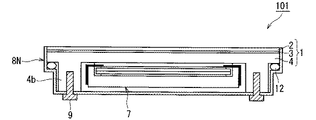
図4は、本発明の実施の形態2に係る表示装置101の概略構成を示す分解斜視図である。図5は、本発明の実施の形態2に係る表示装置101の断面図である。
<
FIG. 4 is an exploded perspective view showing a schematic configuration of the
図4および図5を参照して、表示装置101は、図1および図2の表示装置100と比較して、筐体8の代わりに筐体8Nを備える点と、パッキン12をさらに備える点が異なる。表示装置101のそれ以外の構成は、表示装置100と同様なので詳細な説明は繰り返さない。
4 and 5, the
筐体8Nは、筐体8と比較して、形状が異なる。筐体8Nのそれ以外の構成は、筐体8と同様なので詳細な説明は繰り返さない。筐体8Nの形状は、図3の筐体8Aの形状と同様である。なお、図4では、筐体8Nの形状を簡略化して示している。
The shape of the
なお、保護板1の樹脂材4は、実施の形態1の構成と同様の構成により、ネジ9により、筐体8Nに着脱可能に固定される。
The
パッキン12の形状は、閉ループ状である。パッキン12は、弾性を有する材料(例えば、ゴム)で構成される。 The shape of the packing 12 is a closed loop shape. The packing 12 is made of an elastic material (for example, rubber).
なお、図3に示す実施の形態1の変形例に係る表示装置100Aでは、液晶表示装置7および保護板1Aが筐体8Aに収容された状態では、筐体8Aと樹脂材4Aとの間には隙間が設けられる。
In the
そこで、実施の形態2に係る表示装置101では、パッキン12が、筐体8Nと樹脂材4との間に設けられる隙間を埋めるように、設けられる。具体的には、該隙間において、筐体8Nと樹脂材4とによりパッキン12を挟むことにより、パッキン12を圧縮して、パッキン12の反発力により、隙間がパッキン12により埋められる。
Therefore, in the
以上の構成により、本実施の形態に係る表示装置100Aでは、実施の形態1の効果に加え、表示装置100Aの外部から、表示装置100Aの内部に水が浸入することを防ぐことができる。すなわち、表示装置100Aは、防水機能を有する。
With the configuration described above, in
すなわち、表示装置100Aは、実施の形態1と同様に、ガラスを利用した保護板の破損時における、安全性の確保とメンテナンスの容易性とを両立することができるとともに、防水機能を有する。
That is, as in the first embodiment, the
<実施の形態2の変形例>
なお、保護板を樹脂材に固定する構造は、ネジを利用した構造に限定されない。保護板を樹脂材に固定する構造を、以下の構造としてもよい。
<Modification of
The structure for fixing the protective plate to the resin material is not limited to a structure using screws. The structure for fixing the protective plate to the resin material may be the following structure.
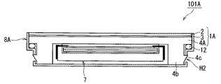
図6は、本発明の実施の形態2の変形例に係る表示装置101Aの断面図である。図6を参照して、表示装置101Aは、図3の表示装置100Aと比較して、パッキン12をさらに備える点が異なる。表示装置101Aのそれ以外の構成は、表示装置100Aと同様なので詳細な説明は繰り返さない。
FIG. 6 is a cross-sectional view of a
表示装置101Aでは、実施の形態2と同様に、パッキン12が、筐体8Aと樹脂材4Aとの間に設けられる隙間を埋めるように、設けられる。
In the
なお、保護板1Aの樹脂材4Aは、実施の形態1の変形例の構成と同様の構成により、突起部4cにより、筐体8Aに着脱可能に固定される。
The
以上の構成により、本実施の形態の変形例に係る表示装置101Aでは、実施の形態2と同様な効果を得ることができる。
With the above configuration, the
<実施の形態3>
図7は、本発明の実施の形態3に係る表示装置102の概略構成を示す分解斜視図である。図8は、本発明の実施の形態3に係る表示装置102の断面図である。
<
FIG. 7 is an exploded perspective view showing a schematic configuration of the
図7および図8を参照して、表示装置102は、図1および図2の表示装置100と比較して、保護板1の代わりに保護板1Bを備える点が異なる。表示装置102のそれ以外の構成は、表示装置100と同様なので詳細な説明は繰り返さない。
Referring to FIGS. 7 and 8,
保護板1Bは、図1および図2の保護板1と比較して、樹脂材4の代わりに樹脂材4Bを含む点が異なる。保護板1Bのそれ以外の構成は、保護板1と同様なので詳細な説明は繰り返さない。保護板1Bは、液晶表示装置7の表示面6を覆うように設けられる。
The
樹脂材4Bは、図1および図2の樹脂材4と比較して、板状部4aの代わりにガラス保持部41aを含む点が異なる。樹脂材4Bのそれ以外の構成は、樹脂材4と同様なので詳細な説明は繰り返さない。すなわち、樹脂材4Bは、ガラス保持部41aと、棒状部4bとを有する。樹脂材4Bは、ガラス保持部41aと、棒状部4bとが一体成型されたものである。
The
ガラス保持部41aは、板状部4aと、枠部4dとを有する。枠部4dの形状は、閉ループ状である。枠部4dは、板状部4aの周縁部に形成される。すなわち、ガラス保持部41aは、枠部4dにより、ガラス2を保持する形状を有する。
The
ガラス2の裏面2bは、接着材3により、樹脂材4の板状部4aに貼り付けられる。この状態において、枠部4dは、表示装置102の外部に露出するように、ガラス2の周囲を覆う。すなわち、枠部4dは、筐体8(表示装置102)の外部に突出する。これにより、ガラス保持部41aを有する樹脂材4Bは、意匠ケースとしての機能を有する。
The
表示装置102では、筐体8は、ガラス2を収容せず、液晶表示装置7を収容する。
In the
なお、保護板1Bの樹脂材4Bは、実施の形態1の構成と同様の構成により、ネジ9により、筐体8に着脱可能に固定される。
In addition, the
以上の構成により、本実施の形態に係る表示装置102では、ガラス保持部41aを有する樹脂材4Bは、意匠ケースとして使用される。これにより、実施の形態1の効果に加え、ガラス2と樹脂材4B(意匠ケース)とにより、筐体8の取付けバラツキによる段差を生じることなく、安定した外観品質を実現できる。すなわち、ガラスを利用した保護板の破損時における、安全性の確保とメンテナンスの容易性とを両立することができるとともに、安定した外観品質を実現できる。
With the above configuration, in
なお、本実施の形態に係る表示装置102に、実施の形態2に示したパッキン12を利用した構成を適用してもよい。この場合、表示装置102において、筐体8の代わりに筐体8Nが用いられる。また、パッキン12が、筐体8Nと樹脂材4Bとの間に設けられる隙間を埋めるように、設けられる。
Note that a configuration using the packing 12 described in
<実施の形態3の変形例>
なお、保護板を樹脂材に固定する構造は、ネジを利用した構造に限定されない。保護板を樹脂材に固定する構造を、以下の構造としてもよい。
<Modification of
The structure for fixing the protective plate to the resin material is not limited to a structure using screws. The structure for fixing the protective plate to the resin material may be the following structure.
図9は、本発明の実施の形態3の変形例に係る表示装置102Aの断面図である。図9を参照して、表示装置102Aは、図3の表示装置100Aと比較して、保護板1Aの代わりに保護板1Cを備える点が異なる。表示装置102Aのそれ以外の構成は、表示装置100Aと同様なので詳細な説明は繰り返さない。
FIG. 9 is a cross-sectional view of a
保護板1Cは、図8の保護板1Bと比較して、樹脂材4Bの代わりに樹脂材4Cを含む点が異なる。保護板1Cのそれ以外の構成は、保護板1Bと同様なので詳細な説明は繰り返さない。
The
樹脂材4Cは、樹脂材4Bと比較して、棒状部4bに、突起部4cが形成されている点が異なる。樹脂材4Cのそれ以外の構成は、樹脂材4Bと同様なので詳細な説明は繰り返さない。
The
なお、保護板1Cの樹脂材4Cは、実施の形態1の変形例の構成と同様の構成により、突起部4cにより、筐体8Aに着脱可能に固定される。
The
以上の構成により、本実施の形態の変形例に係る表示装置102Aでは、実施の形態3と同様な効果を得ることができる。
With the above configuration, the
なお、本実施の形態の変形例に係る表示装置102Aに、実施の形態2に示したパッキン12を利用した構成を適用してもよい。この場合、パッキン12が、筐体8Aと樹脂材4Cとの間に設けられる隙間を埋めるように、設けられる。
Note that a configuration using the packing 12 described in
<実施の形態4>
図10は、本発明の実施の形態4に係る表示装置103の概略構成を示す分解斜視図である。図11は、本発明の実施の形態4に係る表示装置103の断面図である。
<
FIG. 10 is an exploded perspective view showing a schematic configuration of the
図10および図11を参照して、表示装置103は、図1および図2の表示装置100と比較して、保護板1の代わりに保護板1Dを備える点と、筐体8の代わりに筐体8Nを備える点とが異なる。表示装置103のそれ以外の構成は、表示装置100と同様なので詳細な説明は繰り返さない。保護板1Dは、液晶表示装置7の表示面6を覆うように設けられる。
With reference to FIGS. 10 and 11, the
保護板1Dは、図1および図2の保護板1と比較して、ガラス16をさらに含む点が異なる。保護板1Dのそれ以外の構成は、保護板1と同様なので詳細な説明は繰り返さない。
The
ガラス16の形状は、板状である。ガラス16は、接着材3により、樹脂材4の板状部4aの裏面に貼り付けられる。すなわち、保護板1Dの裏面側に、ガラス16を設ける。したがって、ガラス16は、樹脂材4の板状部4aと液晶表示装置7との間に設けられる。すなわち、ガラス16は、保護板1Dの樹脂材4と液晶表示装置7との間に設けられる。
The shape of the
なお、保護板1Dの樹脂材4は、実施の形態1の構成と同様の構成により、ネジ9により、筐体8Nに着脱可能に固定される。
The
以上説明したように、本実施の形態に係る表示装置103では、保護板1Dの裏面側にガラス16を設ける。これにより、樹脂材4を構成する樹脂材料から発生するアウトガスが、接着材5に侵入し気泡となる事を防止することができる。これにより、信頼性の高い表示装置を提供できる。
As described above, in
また、保護板1Dの樹脂材4は、ネジ9により、筐体8Nに着脱可能に固定される。これにより、実施の形態1と同様な効果を得ることができる。
The
なお、本実施の形態に係る表示装置103に、実施の形態2に示したパッキン12を利用した構成を適用してもよい。この場合、パッキン12が、筐体8Nと樹脂材4との間に設けられる隙間を埋めるように、設けられる。
Note that a configuration using the packing 12 shown in
また、本実施の形態に係る表示装置103において、樹脂材4の代わりに、実施の形態3に示した樹脂材4Bを用いた構成としてもよい。これにより、実施の形態3と同様な効果を得ることができる。すなわち、ガラス保持部41aを有する樹脂材4Bを、意匠ケースとして機能させることができる。
Further, in the
また、表示装置103において、筐体8Nの代わりに筐体8を用いる構成としてもよい。
Further, the
<実施の形態4の変形例>
なお、保護板を樹脂材に固定する構造は、ネジを利用した構造に限定されない。保護板を樹脂材に固定する構造を、以下の構造としてもよい。
<Modification of
The structure for fixing the protective plate to the resin material is not limited to a structure using screws. The structure for fixing the protective plate to the resin material may be the following structure.
図12は、本発明の実施の形態4の変形例に係る表示装置103Aの断面図である。図12を参照して、表示装置103Aは、図3の表示装置100Aと比較して、保護板1Aの代わりに保護板1Eを備える点が異なる。表示装置103Aのそれ以外の構成は、表示装置100Aと同様なので詳細な説明は繰り返さない。
FIG. 12 is a cross-sectional view of a
保護板1Eは、図11の保護板1Dと比較して、樹脂材4の代わりに樹脂材4Aを含む点が異なる。保護板1Eのそれ以外の構成は、保護板1Dと同様なので詳細な説明は繰り返さない。
The
樹脂材4Aは、樹脂材4と比較して、棒状部4bに、突起部4cが形成されている点が異なる。樹脂材4Aのそれ以外の構成は、樹脂材4と同様なので詳細な説明は繰り返さない。
The
なお、保護板1Eの樹脂材4Aは、実施の形態1の変形例の構成と同様の構成により、突起部4cにより、筐体8Aに着脱可能に固定される。
The
以上の構成により、本実施の形態の変形例に係る表示装置103Aでは、実施の形態4と同様な効果を得ることができる。
With the above configuration, the
なお、本実施の形態の変形例に係る表示装置103Aに、実施の形態2に示したパッキン12を利用した構成を適用してもよい。この場合、パッキン12が、筐体8Aと樹脂材4Aとの間に設けられる隙間を埋めるように、設けられる。
Note that a configuration using the packing 12 described in the second embodiment may be applied to the
また、本実施の形態の変形例に係る表示装置103Aにおいて、樹脂材4Aの代わりに、実施の形態3の変形例に示した樹脂材4Cを用いた構成としてもよい。これにより、実施の形態3の変形例と同様な効果を得ることができる。すなわち、ガラス保持部41aを有する樹脂材4Cを、意匠ケースとして機能させることができる。
Further, in the
なお、本発明は、その発明の範囲内において、実施の形態、実施の形態の変形例を自由に組み合わせたり、実施の形態、実施の形態の変形例を適宜、変形、省略することが可能である。 It should be noted that within the scope of the invention, the present invention can be freely combined with the embodiments and modifications of the embodiments, or can be appropriately modified and omitted with reference to the embodiments and modifications of the embodiments. is there.
例えば、保護板の樹脂材を、筐体に着脱可能に固定する構成は、実施の形態1のネジ9を用いた構成、または、実施の形態1の変形例の突起部4cを用いた構成に限定されない。保護板の樹脂材を、筐体に着脱可能に固定する構成は、例えば、樹脂材4に凹部を設け、当該凹部に、筐体に設けた突起部を係合させる構成であってもよい。
For example, the configuration in which the resin material of the protective plate is detachably fixed to the housing is a configuration using the
1,1A,1B,1C,1D,1E 保護板、2 ガラス、4,4A,4B,4C 樹脂材、4b 棒状部、4c 突起部、6 表示面、7 液晶表示装置、8,8A,8N 筐体、9 ネジ、12 パッキン、16 ガラス、41a ガラス保持部、100,100A,101,101A,102,102A,103,103A 表示装置、H2 穴。 1, 1A, 1B, 1C, 1D, 1E Protection plate, 2 glass, 4, 4A, 4B, 4C Resin material, 4b Bar-shaped part, 4c Projection part, 6 Display surface, 7 Liquid crystal display device, 8, 8A, 8N Body, 9 screws, 12 packing, 16 glass, 41a glass holding part, 100, 100A, 101, 101A, 102, 102A, 103, 103A display device, H2 hole.
Claims (5)
前記液晶表示装置を収容する筐体と、
前記表示面を覆う保護板と、を備え、
前記保護板は、
ガラスと、
前記ガラスに貼り付けられる樹脂材とを含み、
前記保護板の前記樹脂材は、前記筐体に着脱可能に固定され、
前記筐体と前記樹脂材との間には隙間が設けられ、
前記表示装置は、さらに、
前記隙間を埋めるパッキンを備え、
前記パッキンは、前記液晶表示装置の側面全体を囲むように設けられ、
前記パッキンは、前記表示面と直交する方向において、前記樹脂材と前記筐体との間に設けられる
表示装置。 A liquid crystal display device having a display surface for displaying an image;
A housing for housing the liquid crystal display device;
A protective plate covering the display surface,
The protective plate is
Glass,
Including a resin material to be attached to the glass,
The resin material of the protection plate is detachably fixed to the housing ,
A gap is provided between the housing and the resin material,
The display device further includes:
A packing for filling the gap,
The packing is provided so as to surround the entire side surface of the liquid crystal display device,
The packing is a display device provided between the resin material and the casing in a direction orthogonal to the display surface .
前記筐体を介してネジが挿入されるネジ固定部を有し、
前記保護板の前記樹脂材は、前記ネジの締付け力により、前記筐体に固定される
請求項1に記載の表示装置。 The resin material is
A screw fixing portion into which a screw is inserted through the housing;
The display device according to claim 1, wherein the resin material of the protection plate is fixed to the housing by a tightening force of the screw.
前記樹脂材は、
前記筐体における前記穴の周辺部に係合する突起部を有する
請求項1に記載の表示装置。 The housing is provided with a hole,
The resin material is
The display device according to claim 1, further comprising a protrusion that engages with a peripheral portion of the hole in the housing.
前記表示装置の外部に露出するように、前記ガラスの周囲を覆う枠部を有する
請求項1〜3のいずれか1項に記載の表示装置。 The resin material is
Wherein so as to be exposed to the outside of the display device, the display device according to any one of claims 1 to 3 having a frame portion covering the periphery of the glass.
前記保護板の前記樹脂材と前記液晶表示装置との間に設けられる別のガラスを含む
請求項1〜4のいずれか1項に記載の表示装置。 The protective plate further includes:
Display device according to any one of claims 1-4 including another glass provided between the resin material of the protective plate and the liquid crystal display device.
Priority Applications (2)
| Application Number | Priority Date | Filing Date | Title |
|---|---|---|---|
| JP2013048589A JP6168798B2 (en) | 2013-03-12 | 2013-03-12 | Display device |
| US14/203,484 US20140267974A1 (en) | 2013-03-12 | 2014-03-10 | Display apparatus |
Applications Claiming Priority (1)
| Application Number | Priority Date | Filing Date | Title |
|---|---|---|---|
| JP2013048589A JP6168798B2 (en) | 2013-03-12 | 2013-03-12 | Display device |
Publications (3)
| Publication Number | Publication Date |
|---|---|
| JP2014174417A JP2014174417A (en) | 2014-09-22 |
| JP2014174417A5 JP2014174417A5 (en) | 2016-03-31 |
| JP6168798B2 true JP6168798B2 (en) | 2017-07-26 |
Family
ID=51525813
Family Applications (1)
| Application Number | Title | Priority Date | Filing Date |
|---|---|---|---|
| JP2013048589A Active JP6168798B2 (en) | 2013-03-12 | 2013-03-12 | Display device |
Country Status (2)
| Country | Link |
|---|---|
| US (1) | US20140267974A1 (en) |
| JP (1) | JP6168798B2 (en) |
Families Citing this family (5)
| Publication number | Priority date | Publication date | Assignee | Title |
|---|---|---|---|---|
| CN104698692A (en) * | 2013-12-10 | 2015-06-10 | 精工爱普生株式会社 | Electro-optic device and electronic apparatus |
| JP6578873B2 (en) * | 2015-10-15 | 2019-09-25 | 日本精機株式会社 | Display device |
| KR102487053B1 (en) * | 2015-12-16 | 2023-01-09 | 엘지디스플레이 주식회사 | Liquid crystal display device |
| CH713579A1 (en) * | 2017-03-17 | 2018-09-28 | Fgp Capital Sa | System comprising an ice cream or a screen. |
| CN110085130B (en) * | 2019-05-30 | 2021-02-05 | 重庆城市管理职业学院 | Electronic information display device |
Family Cites Families (13)
| Publication number | Priority date | Publication date | Assignee | Title |
|---|---|---|---|---|
| JP4304515B2 (en) * | 2005-10-24 | 2009-07-29 | 船井電機株式会社 | Assembly structure, assembly method, and plasma television |
| US7463734B2 (en) * | 2006-02-03 | 2008-12-09 | Sony Ericsson Mobile Communications Ab | Display window cover assemblies and electronic devices and methods using the same |
| JP2008241949A (en) * | 2007-03-27 | 2008-10-09 | Sony Corp | Display device |
| JP2009212700A (en) * | 2008-03-03 | 2009-09-17 | Olympus Imaging Corp | Cover for display of imaging apparatus, and imaging apparatus |
| US8675147B2 (en) * | 2008-12-26 | 2014-03-18 | Nissha Printing Co., Ltd. | Protection panel provided with touch input function for display window of electronic device, and manufacturing method therefor |
| JP5546136B2 (en) * | 2009-02-03 | 2014-07-09 | キヤノン株式会社 | Image display device |
| JP5399805B2 (en) * | 2009-08-04 | 2014-01-29 | 株式会社ジャパンディスプレイ | Display device |
| JP4945667B2 (en) * | 2010-08-05 | 2012-06-06 | 株式会社東芝 | Display device |
| JP5745811B2 (en) * | 2010-10-21 | 2015-07-08 | 三菱電機株式会社 | Display device |
| JP5702112B2 (en) * | 2010-10-29 | 2015-04-15 | 株式会社ジャパンディスプレイ | Display device |
| JP5039826B2 (en) * | 2010-11-19 | 2012-10-03 | 株式会社朝日ラバー | Structure for improving image visibility of electronic device and electronic device having the structure |
| JP5161992B2 (en) * | 2011-03-31 | 2013-03-13 | 株式会社東芝 | Electronics |
| US9081451B2 (en) * | 2012-08-02 | 2015-07-14 | Chenfeng Optronics Corporation | Capacitive touch panel structure |
-
2013
- 2013-03-12 JP JP2013048589A patent/JP6168798B2/en active Active
-
2014
- 2014-03-10 US US14/203,484 patent/US20140267974A1/en not_active Abandoned
Also Published As
| Publication number | Publication date |
|---|---|
| US20140267974A1 (en) | 2014-09-18 |
| JP2014174417A (en) | 2014-09-22 |
Similar Documents
| Publication | Publication Date | Title |
|---|---|---|
| JP6168798B2 (en) | Display device | |
| JP5892736B2 (en) | Display device | |
| EP2864834B1 (en) | Cover plate in a display, which has a protective supporting bracket at its edge | |
| WO2012161260A1 (en) | Display device | |
| CN108990336B (en) | Electronic device | |
| WO2016026385A1 (en) | Frameless display device | |
| EP3037871B1 (en) | Display device | |
| JP5938858B2 (en) | Display device | |
| WO2013157038A1 (en) | Electronic device | |
| TWI529462B (en) | Liquid crystal displays with reduced light leakage | |
| JP5926379B2 (en) | Display device | |
| JP2010134139A (en) | Display device | |
| JP7064264B2 (en) | Display device | |
| JP2015072380A (en) | Display device | |
| KR20180138311A (en) | Cover window for electronic device and electronic device comprising the same | |
| JP6530949B2 (en) | Medical monitors, electronic devices, and video display units | |
| CN113327511B (en) | Display device and electronic apparatus | |
| JP2014130194A (en) | Display device | |
| JP6025423B2 (en) | Display device | |
| JP2020012969A (en) | Display device and display equipment | |
| JP2012216204A (en) | Electronic device | |
| KR102107996B1 (en) | Display device | |
| US20160139460A1 (en) | Display device | |
| JP2018180103A (en) | Display device | |
| US10310175B2 (en) | Display device |
Legal Events
| Date | Code | Title | Description |
|---|---|---|---|
| A521 | Request for written amendment filed |
Free format text: JAPANESE INTERMEDIATE CODE: A523 Effective date: 20160210 |
|
| A621 | Written request for application examination |
Free format text: JAPANESE INTERMEDIATE CODE: A621 Effective date: 20160210 |
|
| A977 | Report on retrieval |
Free format text: JAPANESE INTERMEDIATE CODE: A971007 Effective date: 20161117 |
|
| A131 | Notification of reasons for refusal |
Free format text: JAPANESE INTERMEDIATE CODE: A131 Effective date: 20161122 |
|
| A521 | Request for written amendment filed |
Free format text: JAPANESE INTERMEDIATE CODE: A523 Effective date: 20170116 |
|
| TRDD | Decision of grant or rejection written | ||
| A01 | Written decision to grant a patent or to grant a registration (utility model) |
Free format text: JAPANESE INTERMEDIATE CODE: A01 Effective date: 20170530 |
|
| A61 | First payment of annual fees (during grant procedure) |
Free format text: JAPANESE INTERMEDIATE CODE: A61 Effective date: 20170627 |
|
| R150 | Certificate of patent or registration of utility model |
Ref document number: 6168798 Country of ref document: JP Free format text: JAPANESE INTERMEDIATE CODE: R150 |
|
| R250 | Receipt of annual fees |
Free format text: JAPANESE INTERMEDIATE CODE: R250 |
|
| R250 | Receipt of annual fees |
Free format text: JAPANESE INTERMEDIATE CODE: R250 |
|
| R250 | Receipt of annual fees |
Free format text: JAPANESE INTERMEDIATE CODE: R250 |
|
| R250 | Receipt of annual fees |
Free format text: JAPANESE INTERMEDIATE CODE: R250 |