JP6167271B2 - Address mapping in HDMI network - Google Patents
Address mapping in HDMI network Download PDFInfo
- Publication number
- JP6167271B2 JP6167271B2 JP2014532359A JP2014532359A JP6167271B2 JP 6167271 B2 JP6167271 B2 JP 6167271B2 JP 2014532359 A JP2014532359 A JP 2014532359A JP 2014532359 A JP2014532359 A JP 2014532359A JP 6167271 B2 JP6167271 B2 JP 6167271B2
- Authority
- JP
- Japan
- Prior art keywords
- network
- network device
- database
- information
- user
- Prior art date
- Legal status (The legal status is an assumption and is not a legal conclusion. Google has not performed a legal analysis and makes no representation as to the accuracy of the status listed.)
- Expired - Fee Related
Links
- 238000013507 mapping Methods 0.000 title description 4
- 238000000034 method Methods 0.000 claims description 25
- 238000004891 communication Methods 0.000 claims description 17
- 230000009471 action Effects 0.000 claims description 12
- 238000001514 detection method Methods 0.000 claims description 3
- 230000008859 change Effects 0.000 description 6
- 230000006870 function Effects 0.000 description 5
- 238000004590 computer program Methods 0.000 description 3
- 230000001419 dependent effect Effects 0.000 description 3
- 238000005516 engineering process Methods 0.000 description 3
- 230000001360 synchronised effect Effects 0.000 description 3
- 230000008901 benefit Effects 0.000 description 2
- 230000005540 biological transmission Effects 0.000 description 2
- 238000010586 diagram Methods 0.000 description 2
- 238000011156 evaluation Methods 0.000 description 2
- 230000008569 process Effects 0.000 description 2
- 230000004044 response Effects 0.000 description 2
- 230000001960 triggered effect Effects 0.000 description 2
- 102100024442 60S ribosomal protein L13 Human genes 0.000 description 1
- 101001118201 Homo sapiens 60S ribosomal protein L13 Proteins 0.000 description 1
- 238000012423 maintenance Methods 0.000 description 1
- 230000003287 optical effect Effects 0.000 description 1
- 230000003068 static effect Effects 0.000 description 1
Images


Classifications
-
- H—ELECTRICITY
- H04—ELECTRIC COMMUNICATION TECHNIQUE
- H04N—PICTORIAL COMMUNICATION, e.g. TELEVISION
- H04N21/00—Selective content distribution, e.g. interactive television or video on demand [VOD]
- H04N21/40—Client devices specifically adapted for the reception of or interaction with content, e.g. set-top-box [STB]; Operations thereof
- H04N21/43—Processing of content or additional data, e.g. demultiplexing additional data from a digital video stream; Elementary client operations, e.g. monitoring of home network or synchronising decoder's clock; Client middleware
- H04N21/436—Interfacing a local distribution network, e.g. communicating with another STB or one or more peripheral devices inside the home
- H04N21/4363—Adapting the video or multiplex stream to a specific local network, e.g. a IEEE 1394 or Bluetooth® network
- H04N21/43632—Adapting the video or multiplex stream to a specific local network, e.g. a IEEE 1394 or Bluetooth® network involving a wired protocol, e.g. IEEE 1394
- H04N21/43635—HDMI
-
- H—ELECTRICITY
- H04—ELECTRIC COMMUNICATION TECHNIQUE
- H04L—TRANSMISSION OF DIGITAL INFORMATION, e.g. TELEGRAPHIC COMMUNICATION
- H04L12/00—Data switching networks
- H04L12/28—Data switching networks characterised by path configuration, e.g. LAN [Local Area Networks] or WAN [Wide Area Networks]
- H04L12/2803—Home automation networks
- H04L12/2805—Home Audio Video Interoperability [HAVI] networks
-
- H—ELECTRICITY
- H04—ELECTRIC COMMUNICATION TECHNIQUE
- H04L—TRANSMISSION OF DIGITAL INFORMATION, e.g. TELEGRAPHIC COMMUNICATION
- H04L12/00—Data switching networks
- H04L12/28—Data switching networks characterised by path configuration, e.g. LAN [Local Area Networks] or WAN [Wide Area Networks]
- H04L12/2803—Home automation networks
- H04L12/2807—Exchanging configuration information on appliance services in a home automation network
- H04L12/2809—Exchanging configuration information on appliance services in a home automation network indicating that an appliance service is present in a home automation network
-
- H—ELECTRICITY
- H04—ELECTRIC COMMUNICATION TECHNIQUE
- H04L—TRANSMISSION OF DIGITAL INFORMATION, e.g. TELEGRAPHIC COMMUNICATION
- H04L41/00—Arrangements for maintenance, administration or management of data switching networks, e.g. of packet switching networks
- H04L41/12—Discovery or management of network topologies
-
- H—ELECTRICITY
- H04—ELECTRIC COMMUNICATION TECHNIQUE
- H04L—TRANSMISSION OF DIGITAL INFORMATION, e.g. TELEGRAPHIC COMMUNICATION
- H04L61/00—Network arrangements, protocols or services for addressing or naming
- H04L61/09—Mapping addresses
- H04L61/10—Mapping addresses of different types
- H04L61/103—Mapping addresses of different types across network layers, e.g. resolution of network layer into physical layer addresses or address resolution protocol [ARP]
-
- H—ELECTRICITY
- H04—ELECTRIC COMMUNICATION TECHNIQUE
- H04N—PICTORIAL COMMUNICATION, e.g. TELEVISION
- H04N21/00—Selective content distribution, e.g. interactive television or video on demand [VOD]
- H04N21/40—Client devices specifically adapted for the reception of or interaction with content, e.g. set-top-box [STB]; Operations thereof
- H04N21/43—Processing of content or additional data, e.g. demultiplexing additional data from a digital video stream; Elementary client operations, e.g. monitoring of home network or synchronising decoder's clock; Client middleware
- H04N21/436—Interfacing a local distribution network, e.g. communicating with another STB or one or more peripheral devices inside the home
- H04N21/43615—Interfacing a Home Network, e.g. for connecting the client to a plurality of peripherals
-
- H—ELECTRICITY
- H04—ELECTRIC COMMUNICATION TECHNIQUE
- H04N—PICTORIAL COMMUNICATION, e.g. TELEVISION
- H04N21/00—Selective content distribution, e.g. interactive television or video on demand [VOD]
- H04N21/60—Network structure or processes for video distribution between server and client or between remote clients; Control signalling between clients, server and network components; Transmission of management data between server and client, e.g. sending from server to client commands for recording incoming content stream; Communication details between server and client
- H04N21/61—Network physical structure; Signal processing
- H04N21/6106—Network physical structure; Signal processing specially adapted to the downstream path of the transmission network
- H04N21/6125—Network physical structure; Signal processing specially adapted to the downstream path of the transmission network involving transmission via Internet
-
- H—ELECTRICITY
- H04—ELECTRIC COMMUNICATION TECHNIQUE
- H04N—PICTORIAL COMMUNICATION, e.g. TELEVISION
- H04N21/00—Selective content distribution, e.g. interactive television or video on demand [VOD]
- H04N21/60—Network structure or processes for video distribution between server and client or between remote clients; Control signalling between clients, server and network components; Transmission of management data between server and client, e.g. sending from server to client commands for recording incoming content stream; Communication details between server and client
- H04N21/63—Control signaling related to video distribution between client, server and network components; Network processes for video distribution between server and clients or between remote clients, e.g. transmitting basic layer and enhancement layers over different transmission paths, setting up a peer-to-peer communication via Internet between remote STB's; Communication protocols; Addressing
- H04N21/64—Addressing
- H04N21/6402—Address allocation for clients
-
- H—ELECTRICITY
- H04—ELECTRIC COMMUNICATION TECHNIQUE
- H04L—TRANSMISSION OF DIGITAL INFORMATION, e.g. TELEGRAPHIC COMMUNICATION
- H04L2101/00—Indexing scheme associated with group H04L61/00
- H04L2101/60—Types of network addresses
- H04L2101/618—Details of network addresses
- H04L2101/622—Layer-2 addresses, e.g. medium access control [MAC] addresses
Description
本出願は、ホームエンタテイメントネットワーク(home entertainment network)のためのネットワーク装置に関する。本発明は、また、ホームエンタテイメントネットワークにおけるオーディオビデオ及びデータストリームの制御及び再ルーティングのためのホームエンタテイメントネットワーク、データテーブル及び方法に関する。 The present application relates to a network device for a home entertainment network. The invention also relates to a home entertainment network, data table and method for the control and rerouting of audio-video and data streams in a home entertainment network.
TVセット、セットトップボックス、DVDまたはブルーレイ(Blu-ray)ディスクプレイヤ、MP3プレイヤなどのホームエンタテイメント装置は、特に、いわゆるHDMIインタフェースを装備した場合、ますます一般的となっている。HDMIは、高精細度マルチメディアインターフェース(High Definition Multimedia Interface)の略称で、非圧縮デジタルデータを伝送するためのコンパクトオーディオ/ビデオインタフェースである。HDMIは、セットトップボックス、DVDプレイヤ、ブルーレイディスクプレイヤ、パーソナルコンピュータ、ビデオゲームコンソール、及びAVレシーバなどの、デジタルオーディオ/ビデオソースを互換性のあるデジタルオーディオ装置、コンピュータモニタ及びデジタルテレビに接続することを可能にする。HDMIは、デジタルオーディオ及び家電制御(CEC:Consumer Electronics Control)接続を8チャンネルまで、標準の、強化された、及び高精細のビデオを含む任意のテレビ又はPCビデオフォーマットを一本のケーブル上でサポートしている。CECは、必要に応じてHDMI装置が互いに制御することを可能にし、ユーザが1つのリモコンハンドセットで複数の装置を操作することを可能にする。 Home entertainment devices such as TV sets, set-top boxes, DVD or Blu-ray disc players, MP3 players and the like are becoming increasingly common, especially when equipped with so-called HDMI interfaces. HDMI is an abbreviation for High Definition Multimedia Interface, and is a compact audio / video interface for transmitting uncompressed digital data. HDMI connects digital audio / video sources, such as set-top boxes, DVD players, Blu-ray disc players, personal computers, video game consoles, and AV receivers, to compatible digital audio devices, computer monitors, and digital televisions. Enable. HDMI supports up to 8 channels of digital audio and consumer electronics control (CEC) connections, and any television or PC video format, including standard, enhanced, and high-definition video, on a single cable. doing. CEC allows HDMI devices to control each other as needed and allows a user to operate multiple devices with a single remote control handset.
2009年5月28日にリリースされたHDMIバージョン1.4から、HDMI接続された装置間の100MB/sのイーサネット接続を可能にする、HDMIイーサネットチャンネルが規定された。このイーサネットケイパビリティ(capability)は、例えば、TVセット及びビデオプレイヤを含むHDMIネットワークを、他のHDMIネットワークと接続することを可能にする。言い換えると、ユーザの家中に分配されたいくつかのHDMIネットワーク(ホームエンタテイメントネットワークのサブネットワーク)を含むマルチルームホームエンタテイメントネットワークを構築することが可能となる。 From HDMI version 1.4 released on May 28, 2009, an HDMI Ethernet channel was defined that allows 100 MB / s Ethernet connections between HDMI connected devices. This Ethernet capability makes it possible, for example, to connect an HDMI network including a TV set and a video player with other HDMI networks. In other words, it becomes possible to construct a multi-room home entertainment network including several HDMI networks (sub-networks of home entertainment network) distributed throughout the user's house.
特に、ネットワーク内で装置を選択するためのより多くのオプションをユーザに与えるために、そのようなホームエンタテイメントネットワークの更なるケイパビリティに対する要求が増大している。より具体的には、そのようなケイパビリティは、スマートホン、タブレットPC及びノートブック等のようなモバイル装置を、そのような装置が頻繁にコンセントに繋がれたり外されたりしたとしても、サポートすべきである。 In particular, there is an increasing demand for further capabilities of such home entertainment networks in order to give users more options for selecting devices within the network. More specifically, such capabilities should support mobile devices such as smartphones, tablet PCs, notebooks, etc., even if such devices are frequently connected and disconnected. It is.
したがって、本願発明の目的は、モバイル装置を使用している場合でも、拡張されたネットワーク関連のケイパビリティを有するホームエンタテイメントネットワークのネットワーク装置を提供することである。 Accordingly, an object of the present invention is to provide a network device for a home entertainment network having extended network-related capabilities even when using a mobile device.
本願発明の一態様によれば、イーサネット通信ケイパビリティ、HEC、及びCEC(Consumer Electronics Control)通信ケイパビリティを提供するように構成されたネットワークコントローラと、ホームエンタテイメントネットワークのネットワーク装置についての情報、及びネットワーク装置各々の一意の識別子を含むデータベースを生成するように構成されたデータベース生成ユニットと、を含む、ホームエンタテイメントネットワークのためのネットワーク装置が提供される。 According to one aspect of the present invention, a network controller configured to provide Ethernet communication capabilities, HEC, and CEC (Consumer Electronics Control) communication capabilities, information about network devices of a home entertainment network, and each network device There is provided a network device for a home entertainment network, including a database generation unit configured to generate a database including a unique identifier of
言い換えると、当該ネットワーク装置は、技術的には、ネットワーク内の装置についての関連するデータを含むデータベースを生成するケイパビリティを有するユニットを備える。ネットワーク装置についての情報の一部は、ホームエンタテイメントネットワーク内のネットワーク装置の論理及び/又は物理アドレスと関係なく、各ネットワーク装置を識別することを可能とする一意の識別子である。 In other words, the network device technically comprises a unit having the capability of generating a database containing relevant data about the devices in the network. Part of the information about the network device is a unique identifier that allows each network device to be identified regardless of the logical and / or physical address of the network device in the home entertainment network.
HDMI仕様書によれば、例えば当該装置がネットワークから切断され、及び他のHDMIプラグに再接続されたときに、ホームエンタテイメントネットワーク内のネットワーク装置の物理アドレスは変わる可能性がある。結果的に、HDMI仕様書に従って使用される物理アドレスは、スタティック(static)ではなく、従ってユーザに提案されることができるフィーチャ(features)の範囲を制限する時間にわたって信頼できるものではない。同様に変更されることがある、ホームエンタテイメントネットワーク内の装置の論理アドレスにも、同じことが適用される。 According to the HDMI specification, for example, when the device is disconnected from the network and reconnected to another HDMI plug, the physical address of the network device in the home entertainment network may change. As a result, the physical addresses used according to the HDMI specification are not static and are therefore not reliable over time that limits the range of features that can be proposed to the user. The same applies to the logical addresses of devices in the home entertainment network that may change as well.
ホームエンタテイメントネットワーク内の各ネットワーク装置に対し一意の識別子を用いることによって、装置が切断され、及び他のHDMIプラグに再接続されたとしても、常にかつどんな時も、特定のネットワーク装置を識別し、従ってアドレス指定することが可能となる。ネットワーク装置の一意の識別子を含むデータベースは、従って、例えば、割り当てられた物理アドレス/論理アドレスを各ネットワーク装置の一意の識別子にマッピングすることを可能とする。このマッピングにより、フィーチャ及びアプリケーションは、ネットワークから切断されてネットワークに戻ってくるとすぐに、当該装置を再識別することが可能となる。当該装置は、任意の自由なHDMIコネクタに接続されることができ、物理アドレスが変わっても、過去に既にネットワーク接続されていたネットワーク装置として、一意の識別子を介してネットワーク装置が識別され得る。言い換えると、ネットワーク装置に対して一意の識別子を用いることにより可能であるアドレスマッピングによって、ネットワーク装置は、ネットワークトポロジー内の以前の位置も現在の新しい位置も識別され得る。 By using a unique identifier for each network device in the home entertainment network, it will always identify a particular network device, even if the device is disconnected and reconnected to other HDMI plugs, Therefore, it is possible to specify an address. A database containing network device unique identifiers thus makes it possible, for example, to map assigned physical / logical addresses to the unique identifier of each network device. This mapping allows features and applications to re-identify the device as soon as it is disconnected from the network and returned to the network. The device can be connected to any free HDMI connector, and even if the physical address changes, the network device can be identified through a unique identifier as a network device already connected to the network in the past. In other words, the address mapping, which is possible by using a unique identifier for the network device, allows the network device to identify both the previous location and the current new location in the network topology.
好適な実施形態において、当該一意の識別子は、ネットワークコントローラに割り当てられたいわゆるMACアドレスである。MACアドレスは、メディアアクセスコントロールアドレス(Media Access Control Address)の略称であり、物理ネットワークセグメント上での通信のためにネットワークインタフェースに割り当てられた一意の識別子である。MACアドレスは、多くのネットワーク技術、及びイーサネットを含むIEEE802のネットワーク技術に最も多く使用されている。 In a preferred embodiment, the unique identifier is a so-called MAC address assigned to the network controller. The MAC address is an abbreviation for Media Access Control Address, and is a unique identifier assigned to a network interface for communication on a physical network segment. MAC addresses are most commonly used in many network technologies and IEEE 802 network technologies including Ethernet.
本願発明のさらなる態様によれば、本願発明にかかるネットワーク装置を2以上含むホームエンタテイメントネットワークが提供される。 According to a further aspect of the present invention, there is provided a home entertainment network including two or more network devices according to the present invention.
本願発明のさらなる態様によれば、本願発明にかかるネットワーク装置のメモリに格納されたデータテーブルが提供される。当該データテーブルは、特定のネットワーク装置の動作を示す第1の情報と、前記特定のネットワーク装置のネットワークアドレスを示す第2の情報と、当該動作の時刻及び日付を示す第3の情報と、前記ネットワーク装置の一意の識別子を示す第4の情報と、を含む。ここで、当該データテーブルは、本明細書で言及された情報に限定されないことに留意すべきである。当該データテーブルは、IPアドレスや、他のネットワーク装置に関するデータなどの情報をさらに含んでもよい。 According to a further aspect of the present invention, there is provided a data table stored in a memory of a network device according to the present invention. The data table includes first information indicating an operation of a specific network device, second information indicating a network address of the specific network device, third information indicating a time and date of the operation, And fourth information indicating a unique identifier of the network device. Here, it should be noted that the data table is not limited to the information mentioned in this specification. The data table may further include information such as an IP address and data regarding other network devices.
このデータテーブルに、ビデオ再生、ビデオ停止等の、ユーザによって実行されたネットワーク装置の動作を登録することが可能である。データテーブルに格納されたデータは、ユーザによって過去に選択された動作の詳細な実態(picture)を与える。ネットワーク装置の一意の識別子、好適にはMACアドレスを用いることによって、論理/物理アドレスが変わったときでも、ネットワーク装置は常に識別され得る。 In this data table, it is possible to register the operation of the network device executed by the user, such as video playback and video stop. The data stored in the data table gives a detailed picture of the action previously selected by the user. By using a unique identifier of the network device, preferably a MAC address, the network device can always be identified even when the logical / physical address changes.
本願発明のさらなる態様によると、ホームエンタテイメントネットワークにおけるオーディオ、ビデオ及びデータストリームを制御し、再ルーティングするための方法であって、前記ホームエンタテイメントネットワークのネットワーク装置についての情報、及び前記ネットワーク装置各々の一意の識別子を含むデータベースを生成するステップを含む方法が提供される。 According to a further aspect of the present invention, there is provided a method for controlling and rerouting audio, video and data streams in a home entertainment network, comprising information about the network devices of the home entertainment network and the uniqueness of each of the network devices. A method is provided that includes generating a database that includes a plurality of identifiers.
ネットワーク装置についての当該情報は、例えば、ネットワークアドレス、具体的には論理アドレス及び物理アドレス、及び/又はユーザによる前記ネットワーク装置の動作に関する情報及び/又は前記ネットワーク装置に割り当てられたプリファレンス(preferences)についての情報であってもよい。 The information about the network device can be, for example, a network address, specifically a logical address and a physical address, and / or information about the operation of the network device by a user and / or preferences assigned to the network device. It may be information about.
ホームエンタテイメントネットワークが、2以上のサブネットワークを含む場合、前記情報は、サブネットワークの識別子を含むものであってもよい。 When the home entertainment network includes two or more subnetworks, the information may include an identifier of the subnetworks.
さらに別の態様によれば、コンピュータプログラムは、好適にはネットワーク装置のファームウェアの形態であって、コントローラ、好適にはネットワークデバイスコントローラに本願発明に係る方法のステップを実行させるプログラム手段を含み、前記コンピュータプログラムが、コントローラ及びコントローラ上に格納された命令を有するコンピュータ読み取り可能な非一時的媒体上で実行されるとき、コントローラ上で実行されるとき、コントローラに本願発明に係る方法のステップを実行させるプログラムが提供される。 According to yet another aspect, the computer program is preferably in the form of firmware of a network device, comprising program means for causing a controller, preferably a network device controller, to execute the steps of the method according to the invention, When a computer program is executed on a controller and a computer-readable non-transitory medium having instructions stored on the controller, the controller causes the controller to execute the steps of the method according to the present invention when executed on the controller. A program is provided.
本発明の好適な実施形態は、従属項において定義される。これは、クレームされた方法は、クレームされたネットワーク装置及び従属項において定義されたのと同様の及び/または同一の好適な実施形態を有するものであると理解されたい。 Preferred embodiments of the invention are defined in the dependent claims. It should be understood that the claimed method has a preferred embodiment similar to and / or identical to that defined in the claimed network device and dependent claims.
本願発明は、前記ホームエンタテイメントネットワーク、好適にはHDMIネットワークのネットワーク装置についての情報及び各ネットワーク装置の一意の識別子を含むデータベースを、好適には少なくとも1つのデータテーブルの形式で生成するためのアイデアに基づく。データベースに格納された一意の識別子は、ホームエンタテイメントネットワーク内の位置にかかわらず、ネットワーク装置を一義的に識別することを可能にする。ネットワーク装置がその位置を変更し、その結果物理アドレスも第1の値から第2の値に変化したとしても、ネットワーク装置は、一意の識別子を介して、以前に第1の値で物理アドレスを持っていた装置として識別され得る。また、論理アドレスも変化してもよい。 The present invention is based on the idea for generating a database containing information about the home entertainment network, preferably an HDMI network device and a unique identifier of each network device, preferably in the form of at least one data table. Based. The unique identifier stored in the database makes it possible to uniquely identify a network device regardless of its location in the home entertainment network. Even if the network device changes its location and, as a result, the physical address also changes from the first value to the second value, the network device uses the unique identifier to change the physical address to the previous first value. It can be identified as the device it had. The logical address may also change.
本願発明のこれら及び他の態様は、本明細書で後述される実施形態から明らかであり、それらを参照して以下でより詳細に説明されるであろう。以下の図面において、
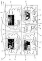
図1において、ホームエンタテイメントネットワークの具体例が示され、参照番号10で指定されている。この具体例は、ネットワーク装置及びそれらの機能を説明するのに役立つ。しかしながら、本願発明は、このようなホームエンタテイメントネットワークに限定されないことに留意すべきである。 In FIG. 1, a specific example of a home entertainment network is shown and designated by reference numeral 10. This example helps to explain the network devices and their functions. However, it should be noted that the present invention is not limited to such a home entertainment network.
本願発明との関係において、ホームエンタテイメントネットワークは、家庭内の全ての形式のデジタルメディアを格納し、管理し及びアクセスするように同様に設計されたネットワーク装置を連結するように設計された任意のデータネットワークを意味する。このようなホームエンタテイメントネットワークの一例がHDMIネットワーク(同様に、HDMIのサブネットワークを含むことができる)であり、ネットワークケイパビリティを提供するためのHDMIインタフェースを有するネットワーク装置である。HDMIは、非圧縮デジタルデータを伝送するための規格であり、高精細度マルチメディアインターフェース(High Definition Multimedia Interface)の略称である。以下では、図1に示されたホームエンタテイメントネットワーク10は、いくつかのHDMIサブネットワークを含むHDMIネットワーク11であると仮定する。しかしながら、本願発明は、HDMIネットワークに限定されない。 In the context of the present invention, a home entertainment network is any data designed to link network devices that are similarly designed to store, manage and access all forms of digital media in the home. Means network. An example of such a home entertainment network is an HDMI network (which can also include an HDMI sub-network), which is a network device having an HDMI interface for providing network capabilities. HDMI is a standard for transmitting uncompressed digital data, and is an abbreviation for High Definition Multimedia Interface. In the following, it is assumed that the home entertainment network 10 shown in FIG. 1 is an HDMI network 11 including several HDMI sub-networks. However, the present invention is not limited to the HDMI network.
図1に示されるHDMIネットワーク11は、いくつかの部屋に及び、本実施形態においては、住居内の4つの部屋に及ぶ。HDMIネットワーク11は、各部屋に1つ、4つのサブネットワーク12、14、16、18を含む。
The HDMI network 11 shown in FIG. 1 covers several rooms, and in this embodiment, covers four rooms in a residence. The HDMI network 11 includes four
各サブネットワーク12、14、16、18は、少なくとも1つのネットワーク装置、好適には少なくとも2つのネットワーク装置を含み、そのうち1つは、シンクデバイスとして作動し、他はソースデバイスとして作動するものを含む。シンクデバイスは、オーディオ/ビデオストリームを受信し、当該ビデオ及びオーディオストリームをそれぞれ表示または再生する。ソースデバイスは、同様に、例えばブルーレイディスクからオーディオ/ビデオストリームを生成し、このストリームをシンクデバイスに伝送する。
Each
HDMI仕様書(バージョン1.4)によれば、HDMIサブネットワークは、概して、ただ1つのシンクデバイスと、複数のソースデバイスとを含む。本実施形態において、この制限的なサブネットワークの構造を用いるとしても、本願発明はそれには限定されず、サブネットワークは、いくつかのシンクデバイス及びソースデバイスをも含むものであってもよい。ネットワークに1以上のシンクデバイスが存在する場合、他のシンクデバイスは、限定されたネットワーク機能のみを有する。 According to the HDMI specification (version 1.4), an HDMI subnetwork generally includes only one sink device and multiple source devices. Even if this restrictive subnetwork structure is used in the present embodiment, the present invention is not limited thereto, and the subnetwork may include several sink devices and source devices. When one or more sink devices exist in the network, the other sink devices have only limited network functions.
図1に示す例では、12〜18の4つのサブネットワークは、それぞれ、TVセットの形のシンクデバイス120、140、160,180と、ブルーレイディスクプレイヤの形の少なくとも1つのソースデバイス122、162、182及び/又はセットトップボックス141を含む。サブネットワーク120、160及び180は、さらなるソースデバイス、例えば、モバイル装置121、好適にはノートブック及びセットトップボックス161及び181を含む。
In the example shown in FIG. 1, four
ネットワーク装置としても称される全てのシンク及びソースデバイスは、サブネットワーク内のソースデバイスをシンクデバイスと連結するためのHDMIインタフェースが装備されている。 All sinks and source devices, also referred to as network devices, are equipped with an HDMI interface for connecting source devices in the sub-network with the sink devices.
HDMIネットワーク11は、好適にはルータ機能を備えるネットワークスイッチ20も含む。スイッチ20は、異なるサブネットワーク間の通信経路が確立されるように、サブネットワークの境界を越えて通信を可能にする。
The HDMI network 11 also preferably includes a
図1に示すように、データライン22は、サブネットワーク12〜18内で、スイッチ20と他のネットワーク装置間に提供される。例えば、サブネットワーク12のブルーレイディスク装置122は、データライン22を介してスイッチ20と接続される。スイッチ20に連結されるネットワーク装置は、図1においてプロキシとして参照される。
As shown in FIG. 1, a
データライン22は、好適には、TCP/IPプロトコルに従ってデータを伝送するイーサネットデータラインである。しかしながら、オーディオ/ビデオコンテンツのストリーミングを可能とする他の通信プロトコルを用いることも、当然可能である。
The
さらに、例えば、既知のWLAN(Wireless Local Area Network)標準を用いることにより、サブネットワークとスイッチとの間のデータ通信を無線で実現することも考えられ得る。 Further, for example, by using a known WLAN (Wireless Local Area Network) standard, it may be possible to realize data communication between the sub-network and the switch wirelessly.
単に完全を期すために、ネットワーク10は、イーサネットラインを介してスイッチ20と連結されたパーソナルコンピュータ26を含むものであってもよい。
For the sake of completeness, the network 10 may include a
スイッチ20を介したサブネットワーク間の通信は、各々のネットワーク機器に割り当てられた一意のアドレスを必要とすることは明らかである。HDMI仕様書は、アドレススキームを定義しているが、このスキームは、そのようなアドレスの曖昧さによる通信を可能としていない。例えば、HDMIサブネットワーク12、14、16、18は、図1に示されているようにアドレス0.0.0.0が通常割り当てられることが、HDMI仕様書から分かる。シンクデバイスと連結されたソースデバイスは、サブネットワーク12、16、及び18における場合のように、アドレス1.0.0.0又は2.0.0.0が割り当てられる。
Obviously, communication between the sub-networks via the
ホームエンタテイメントネットワーク10のシンクデバイス120、140、160、180は、同一のHDMIアドレスをもっているため、これらの装置間の通信は不可能となることは容易に分かることである。
Since the
このアドレスの問題を解決するために、拡張アドレススキームが用いられる。この拡張アドレススキームの基盤は、各サブネットワークに対し一意のサブネットワークの識別子である。例えば、サブネットワーク12に識別子“A”が割り当てられ、サブネットワーク14に識別子“B”が割り当てられている、などである。従って、0.0.0.0のようなHDMIアドレスと“A”のようなサブネットワークの識別子との組み合わせは、ホームエンタテイメントネットワーク10内の1つのネットワーク装置を一義的に識別する。この拡張ネットワークスキームは、2009年3月31日に出願された欧州特許出願09156939の主題であり、その内容は参照により本明細書に組み込まれている。
To solve this address problem, an extended address scheme is used. The basis of this extended address scheme is a unique subnetwork identifier for each subnetwork. For example, the identifier “A” is assigned to the
したがって、図1に示すネットワーク構造は、例えば、一のサブネットワーク12のソースデバイス122と他のサブネットワーク14のシンクデバイス140との間の、イーサネットを用いたデータ伝送(例えば、ビデオストリーミング)を可能とする。
Accordingly, the network structure shown in FIG. 1 enables, for example, data transmission (for example, video streaming) using Ethernet between the
ホームエンタテイメントネットワーク10のこのケイパビリティを、ユーザが容易に達成可能とするように、ネットワーク装置は、好適には、装置データテーブル(device data table)及び動作履歴データテーブル(operation history data table)を含むデータベースを使用する。 In order to make this capability of the home entertainment network 10 easily achievable by the user, the network device is preferably a database that includes a device data table and an operation history data table. Is used.
第1のデータテーブル、すなわち、装置データテーブルは、ホームエンタテイメントネットワーク10内で過去に認識された全てのネットワーク装置についての情報を含む。そのような装置データテーブルの一例を図3aに示す。本例の装置データテーブルは、ホームエンタテイメントネットワーク10内の各ネットワーク装置につき1つ、11のデータレコードを含む。各データレコードは、ネットワーク装置がログインされた日付及び時刻、ネットワーク装置の論理アドレス、物理アドレス、ネットワーク識別子及びMACアドレスを含む。論理アドレス及び物理アドレスは、HDMI仕様書の一部である。例えば、サブネットワーク12のTVセット120は、装置データテーブルの第1のデータレコードによって記述されている。TVセット120は、2011年2月10日の午後5時に初めてログインされ、又は電源が入れられた。TVセット120の物理アドレスは0.0.0.0であり、論理アドレスは0であり、TVセット120は、ネットワーク識別子“A”が割り当てられたサブネットワークのメンバーである。さらに、本実施形態において、TVセット120のMACアドレスは、01−01−01−01−01−AAである。当技術分野で知られているように、MACアドレスは、ネットワーク装置、または少なくとも、ネットワーク装置のネットワークインタフェースに対し、当該ネットワーク装置の製造業者によって割り当てられ、当該ネットワーク装置のライフタイムにわたって一致する一意の識別子である。
The first data table, ie, the device data table, includes information about all network devices recognized in the past in the home entertainment network 10. An example of such a device data table is shown in FIG. The device data table of this example includes eleven data records, one for each network device in the home entertainment network 10. Each data record includes the date and time when the network device was logged in, the logical address of the network device, the physical address, the network identifier, and the MAC address. The logical address and physical address are part of the HDMI specification. For example, the
本願発明では、一意のネットワーク装置の識別子としてMACアドレスを用いるが、識別子が特定の期間中に変更可能ではなく、変更されることもないことを条件として、他の識別子も使用されることができる。 In the present invention, a MAC address is used as a unique network device identifier, but other identifiers can also be used provided that the identifier is not changeable during a specific period and will not change. .
この装置データベースに基づいて、ホームエンタテイメントネットワーク内の特定のネットワーク装置を見つけること、及びこの装置にデータを送信することが可能となる。ネットワーク装置が、その位置及びそれに従って物理アドレスを変更しても、この特定のネットワーク装置は、今もなお同一のMACアドレスを介して見つけられ、識別されることができる。 Based on this device database, it is possible to find a specific network device in the home entertainment network and transmit data to this device. Even if the network device changes its location and the physical address accordingly, this particular network device can still be found and identified via the same MAC address.
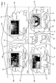
このようなシナリオを説明するための一例が図2に示されている。ここでは、モバイルネットワーク装置121、好適にはノートブックが、図1に示すサブネットワーク12から切断され、サブネットワーク12のTVセット120に後で再接続されている。しかしながら、ユーザは、HDMIケーブルをTVセット120の異なるHDMIコネクタに差し込み、その結果、ネットワーク装置121には、異なる物理アドレス、ここでは3.0.0.0が割り当てられた。この物理アドレスの変化は、図3bのデータテーブル内の第2のレコードに反映されている。このデータテーブルから、物理アドレスが変化しても、MACアドレスは依然として同一で、ネットワーク装置121を一義的に識別するために用いることができることは明らかである。ネットワーク装置121が、例えば異なるサブネットワークのTVセットと連結されるとしても、これはやはり当てはまる。
An example for explaining such a scenario is shown in FIG. Here, the
このような装置データテーブルを構築するための多くの可能性がある。好適な方法としては、ホームエンタテイメントネットワーク10内の可能性のあるアドレス各々にデータパッケージを送信することである。もしネットワーク装置がそれぞれのデータパッケージを受信したら、送信元に応答メッセージ(acknowledge message)を返す。この応答メッセージは受信され、それにより上述したようにデータレコードが生成される。通常、ネットワーク装置は、スタンバイモードであったとしても、応答メッセージを返すことができる。各ネットワーク装置の電源が切られている場合にのみ、それは認識されず、従ってデータレコードの生成につながらない。 There are many possibilities for building such a device data table. A preferred method is to send a data package to each possible address in the home entertainment network 10. If the network device receives each data package, it returns an acknowledgment message to the sender. This response message is received, thereby generating a data record as described above. Normally, the network device can return a response message even in the standby mode. Only when each network device is turned off is it not recognized and therefore does not lead to the generation of a data record.
装置データテーブルは、好適にはネットワーク装置毎に格納されるが、各サブネットワークのプロキシにのみ、このデータテーブルを格納することも可能である。さらに、装置データテーブルの生成をエンハンスするために、同一又は異なるサブネットワークの異なるネットワーク装置の装置データテーブルを同期化させることも可能である。同期化は、本明細書の文脈においては、他の装置データテーブルのデータレコードが収集され、もしこの情報が既に存在しない場合、自分の装置データテーブルに追加されることを意味する。 The device data table is preferably stored for each network device, but it is also possible to store this data table only in the proxy of each subnetwork. Furthermore, it is possible to synchronize device data tables of different network devices in the same or different sub-networks in order to enhance the generation of device data tables. Synchronization, in the context of this specification, means that data records of other device data tables are collected and added to their device data table if this information does not already exist.
例えば、各ネットワーク装置の電源が切られている場合、特定のネットワーク装置に対応するデータレコードは、削除されることにも留意すべきである。 It should also be noted that, for example, if each network device is powered off, the data record corresponding to the particular network device is deleted.
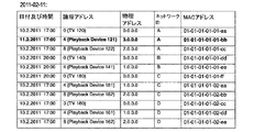
第2のデータテーブル、いわゆる動作履歴データテーブルは、過去にホームエンタテイメントネットワーク10全体で実行された動作を記述するデータレコードを含む。言い換えると、動作履歴データテーブルは、任意のユーザにより課された動作の実態(picture)である。動作履歴データテーブルは、イベントが記録されたログブックと比較され得る。 The second data table, the so-called operation history data table, includes data records that describe operations executed in the past in the entire home entertainment network 10. In other words, the motion history data table is a picture of a motion imposed by an arbitrary user. The operation history data table may be compared with a log book in which events are recorded.
動作履歴データテーブルの一例が、図4に示されている。動作履歴データテーブルのデータレコードは、日付並びに時間、ソースデバイスのアドレス、シンクデバイスのアドレス、ユーザにより課された動作の種類、データ伝送のモード、例えば、再生が一時停止され、又は停止されたポイントの情報を含むタイムスタンプ、及び各動作を課したユーザを定義するユーザIDを含むことが、そこから明らかである。例えば、図4の動作履歴データテーブルの第1のデータレコードは、サブネットワークAのアドレス1.0.0.0を持つソースデバイス(モバイルネットワーク装置121)と、同じサブネットワークAのアドレス0.0.0.0を持つシンクデバイス(TVセット120)との間の再生動作があったという情報を含む。各動作は、2011年2月10日の午後8:30から午後9:45に行われている。タイムスタンプは、0:00:00にセットされ、この動作を課したユーザは、ユーザ1である。 An example of the operation history data table is shown in FIG. The data record of the operation history data table includes the date and time, the address of the source device, the address of the sink device, the type of operation imposed by the user, the mode of data transmission, for example, the point at which playback is paused or stopped It is clear from this that it includes a time stamp containing the information of the user and a user ID defining the user who imposed each action. For example, the first data record in the operation history data table of FIG. 4 includes the source device (mobile network device 121) having the sub-network A address 1.0.0.0 and the same sub-network A address 0.0. .0.0 is included, information indicating that there was a playback operation with the sink device (TV set 120) having 0.0. Each operation is performed on February 10, 2011 from 8:30 pm to 9:45 pm. The time stamp is set to 0:00: 00 and the user who imposed this operation is the user 1.
履歴データテーブルから明らかなように、シンクデバイス同様ソースデバイスのMACアドレスも格納されている。 As is clear from the history data table, the MAC address of the source device is stored as well as the sink device.
動作履歴データテーブルは、好適にはホームエンタテイメントネットワーク10の各ネットワーク装置に格納され、又は、別の方法として少なくとも各サブネットワークのプロキシに格納される。 The operation history data table is preferably stored in each network device of the home entertainment network 10, or alternatively stored at least in the proxy of each subnetwork.
動作履歴データテーブルは、自動的に生成され、データレコードは、再生、再生停止、電源を入れる、スタンバイモードに切り替える、などの動作をユーザが実行した各々の時に追加される。従って、動作履歴データテーブルは、図4に示すように、時間と共に拡大する。例えば、図4の動作履歴データテーブルの2番目に追加されたデータレコードは、サブネットワーク12のソースデバイス121が、午後9:43に再生メディアのタイムポジション0:73:05で再生停止するようにユーザ、すなわちユーザ1によって操作されたという情報を含む。次に追加されたデータレコードは、シンクデバイス、すなわちサブネットワーク12のTVセット120が、ユーザ、すなわちユーザ1によってスタンバイモードに切り替えられたという情報を含む。
An operation history data table is automatically generated, and a data record is added each time the user performs an operation such as playback, playback stop, power on, and switch to standby mode. Therefore, the operation history data table expands with time as shown in FIG. For example, the second added data record in the operation history data table of FIG. 4 is such that the
次の日、ここでは、2011年2月11日の午後8:00に、ユーザ、すなわちユーザ1が、サブネットワーク14(ネットワーク識別子B)のソースデバイス121からシンクデバイス140への再生を、再生メディアのタイムポジション0:73:05において開始する。ソースデバイスからシンクデバイスへの各データのストリーミングのために、イーサネット通信ケイパビリティが使用される。各々のデータレコードが、図4のデータテーブルの最後の行に示されている。
The next day, here, at 8:00 pm on February 11, 2011, the user, that is, user 1, plays the playback from the
シンクデバイス140に対しストリーミングを行うソースデバイス121は、前の物理アドレス1.0.0.0(動作履歴データテーブルの第2のレコード)と比較して異なる物理アドレス、ここでは3.0.0.0を有するが、MACアドレスは依然として同一であり、識別の目的のために用いられることに言及すべきである。
The
動作履歴データテーブルの拡大を制限するために、例えば、選択可能な期間より古いデータレコードを削除する等の選択可能なルールに従って、データレコードを削除、又は上書きすることができる。 To limit the expansion of the operation history data table, the data records can be deleted or overwritten according to selectable rules, such as deleting data records older than the selectable period.
ホームエンタテイメントネットワーク10の各ネットワーク装置は、ユーザによって課された任意の動作を検知し、動作履歴データテーブルに追加されるべき各々のデータレコードを生成するように構成される。ネットワーク装置が、それ自体の動作を検知することのみ可能な場合には、動作履歴データテーブルは、ホームエンタテイメントネットワークのネットワーク装置間で同期化する。結果として、動作履歴データテーブルは全て、同一の情報と、ホームエンタテイメントネットワーク10内の他のネットワーク装置の動作に対応する情報をも含む。 Each network device of the home entertainment network 10 is configured to detect any action imposed by the user and generate each data record to be added to the action history data table. If the network device can only detect its own operation, the operation history data table is synchronized between the network devices of the home entertainment network. As a result, all the operation history data tables also include the same information and information corresponding to the operation of other network devices in the home entertainment network 10.
ホームエンタテイメントネットワーク10内のデータテーブルの同期化は、HDMI仕様書のイーサネットケイパビリティ、HECケイパビリティ、又はCEC(consumer electronic control)のような他の任意の通信標準を用いることにより実行されてもよい。イーサネットは、例えば、異なるサブネットワークのプロキシ間で用いられ、HECは、例えば、1つのサブネットワーク内の装置間で用いられる。両方を組み合わせることも可能である。 The synchronization of the data table in the home entertainment network 10 may be performed by using any other communication standard such as Ethernet capability, HEC capability, or CEC (consumer electronic control) of the HDMI specification. Ethernet is used, for example, between proxies of different sub-networks, and HEC is used, for example, between devices in one sub-network. It is also possible to combine both.
既に前述したように、データテーブルは同期化される。同期化は、例えば、動作が遂行されるとき毎やネットワーク装置の電源が入れられるとき毎にトリガされてもよく、又は例えば、GUI(graphical user interface)又は例えばリモート制御コマンドを介してユーザによって、又は他の任意の選択可能なルールによって、手動でトリガされてもよい。 As already mentioned above, the data tables are synchronized. Synchronization may be triggered, for example, every time an operation is performed or each time a network device is powered on, or by a user via a GUI (graphical user interface) or a remote control command, for example, Or it may be triggered manually by any other selectable rule.
データテーブルの同期化に関して、「マスタ」データテーブル(すなわち、「マスタ」装置データテーブル及び/又は「マスタ」動作履歴データテーブル)を中央に、例えばルータ装置内に保持することも可能であり、従って、全ての装置が、電源が入れられたとき、及び標準のタイムスライスまたはそれらがユーザ動作に関わったときのいずれかの時から一度、データベースを読み出すことができるという利点を有する。もし中央の「マスタ」データテーブルが存在する場合、各ユーザ動作は、この「マスタ」データテーブルに登録されなければならない。 With respect to data table synchronization, it is also possible to keep a “master” data table (ie, a “master” device data table and / or a “master” operation history data table) centrally, for example in a router device. , All devices have the advantage of being able to read the database once when powered on and either from standard time slices or when they are involved in user operations. If a central “master” data table exists, each user action must be registered in this “master” data table.
記載されたデータテーブルの生成及びメンテナンスは、少なくとも一つの主な目的、すなわち、ホームエンタテイメントネットワークのネットワーク装置の動作を制御するためのより多くのオプションをユーザに与えることを果たす。いくつかの例が、以下に提示されている。しかしながら、例の列挙は網羅的ではなく、当然ながら、データベース、特に装置データテーブル及び/又は動作履歴データテーブルに基づいて、更なる例が考えられることに留意すべきである。 The generation and maintenance of the described data table serves to provide the user with more options for controlling the operation of at least one main purpose, namely the network equipment of the home entertainment network. Some examples are presented below. However, it should be noted that the listing of examples is not exhaustive and, of course, further examples are possible based on databases, in particular device data tables and / or operation history data tables.
概して、装置データテーブルで、全てのネットワーク装置は、ネットワーク内の装置、ソースデバイス、シンクデバイス、及び例えばリピータデバイスについての概観を有し、永続的に存在しないモバイル装置も、装置データテーブルに含まれ得る。この装置データテーブルに基づいて、ホームエンタテイメントネットワーク内で利用可能な装置選択の可能性をユーザに提供することができる。 In general, in a device data table, all network devices have an overview of devices, source devices, sink devices, and for example repeater devices in the network, and mobile devices that do not exist permanently are also included in the device data table. obtain. Based on this device data table, the possibility of device selection available in the home entertainment network can be provided to the user.
例えば、ユーザがTVセット120の電源を入れると、装置データテーブル内に登録された、選択のための全てのソースデバイスをリストしたマニュアルが、提示される。これは、例えば、サブネットワーク18のブルーレイディスクプレイヤ182を選択する可能性をユーザに与える。
For example, when the user turns on the
動作履歴データテーブルで、全てのネットワーク機器は、ネットワーク内の動作に関する知識、例えば装置の状態、ストリーミング方向、アクティブなソース、シンク、及びリピータデバイスを有する。再生及び電源動作も共有される。動作履歴データテーブルは、任意の時間に、任意のネットワーク装置上の、動作の現在の状態を提案する。それは、ネットワーク装置間の動作を移動させる可能性も提案し、例えば、ソースデバイスからシンクデバイスへのビデオストリーミングを、ソースデバイスの位置が例えば変わったとしても、他のシンクデバイスにシームレスに移動させることができる。そのような可能性についてのさらに詳細な説明は、以下に続く。 In the operation history data table, all network devices have knowledge about operations in the network, such as device status, streaming direction, active sources, sinks, and repeater devices. Playback and power operations are also shared. The operation history data table proposes the current state of operation on any network device at any time. It also proposes the possibility of moving operations between network devices, for example moving video streaming from a source device to a sink device seamlessly to other sink devices even if the location of the source device changes, for example Can do. A more detailed explanation of such possibilities follows.
概して、そのような動作のオプションは、制御され、多様な方法で、例えば、GUIを介してオプションを表示することにより、専用のコマンドでオプションを選択することにより、顔認識技術により、又は識別タグIDを有する特別なリモートコマンダ装置により、ユーザに提示され得る。 In general, options for such operations are controlled and can be controlled in a variety of ways, for example by displaying options via a GUI, by selecting options with dedicated commands, by face recognition technology, or by identification tags It can be presented to the user by a special remote commander device having an ID.
制御動作を提案するためにデータベースが用いられる例示的なシナリオは、例えば、以下の通りである。 An exemplary scenario in which a database is used to propose a control action is, for example:
ユーザは、モバイルネットワーク装置121、ここではサブネットワーク12のノートブックから、例えば、「ワンタッチプレイ」フィーチャを介してビデオの再生を開始する。ソースデバイスとしてのノートブック121は、その後、サブネットワーク12のシンクデバイスとして作動する、連結されたTVセット120にビデオコンテンツをストリーミングする。ソースデバイス121は、ユーザからの各制御コマンドを登録し、動作履歴データテーブルのためのデータレコードを生成する。このレコードは、例えば、図4の動作履歴データテーブルの第1行目に示されている。
The user starts playing a video from the notebook of the
しばらくして、ユーザは再生を停止し、従ってシンクデバイス120へのストリーミングは停止し、例えば、「システムスタンバイ」フィーチャを介してシンクデバイスの電源を切る。再び、特定のデータレコードが生成され、図4に示すような動作履歴データテーブルに追加される。ここで、2つのデータレコードが追加され、1つはソースデバイス121に関連し、もう1つはシンクデバイス120に関する。
After some time, the user stops playing, and therefore streaming to the
翌日、ユーザは、何らかの理由でノートブック121をホームエンタテイメントネットワーク10から切断する。夜、ユーザは、ノートブック121を再びTVセット120と再接続するが、異なるHDMIコネクタを用いる。その結果、ネットワーク装置121には、例えば、図3bのデータテーブルに示すように、異なる物理アドレス、ここでは3.0.0.0が割り当てられる。しかしながら、MACアドレスは、依然として同一であり、ユーザ1のために前日ソースデバイスとして作動した装置としてこの装置を識別するために用いられることができる。
The next day, the user disconnects the
その後、ユーザはベッドルームへ行き、サブネットワーク14のTVセット140の電源を入れる。サブネットワーク12のプロキシ(ブルーレイディスク装置122)と各プロキシ、ここではTVセット140との間の動作履歴データテーブルの同期化が既に完了した場合、サブネットワーク14のTVセット140のGUI(Graphical User Interface)は、リビングルームでタイムポジション0:73:05において停止された再生を継続するためのオプションを提案するであろう。このオプションを提示するための各々の情報は、動作履歴データテーブル及び装置データテーブルから得られる。図4に示すデータテーブルの第2のデータレコードは、サブネットワーク12のノートブック121が停止されたという情報を与える。履歴データテーブルの2番目のデータレコードに格納されたMACアドレス及び装置データテーブルのこのネットワーク装置の各々のエントリを介して、ノートブック121が現在物理アドレス3.0.0.0を有することを、TVセット140は発見する。この種のマッピングは、データテーブル内の各ネットワーク装置に対する一意の識別子、具体的にはMACアドレスを用いることによって可能となる。
Thereafter, the user goes to the bedroom and turns on the
次のステップで、ユーザは、提案された、リビングルームのノートブック121からのタイムポジション0:73:05における再生の継続を選択する。前述したように、ベッドルームのTVセット140は、動作履歴データテーブル及び装置データテーブルから、リビングルームのノートブック121のネットワークID、論理アドレス及び新たな物理アドレスと、タイムスタンプとを知っている。ベッドルームのTVセット140は、現在、リビングルームのノートブック装置121に対しイーサネットチャンネルを起動する。
In the next step, the user selects to continue the playback at time position 0:73:05 from the
TVセット140からリビングルームのノートブック121に対し、イーサネットチャンネルが起動されると、オーディオ及びビデオのストリーミングが、アプリケーション、例えばDLNA(Digital Living Network Aligns)から開始されうる。他の任意の考え得るアプリケーションが、リビングルームのノートブック装置121からベッドルームのTVセット140にイーサネットチャンネルを介してストリーミングを開始することができる。
When the Ethernet channel is activated from the
オーディオ及びビデオストリームのこの再ルーティング(rerouting)の結果、関係する2つのネットワーク装置121、140によって各々データレコードが生成され、図4に示すように、動作履歴データテーブルに追加される。
As a result of this rerouting of the audio and video streams, data records are respectively generated by the two
これは、前述したデータテーブルの使用方法のほんの一例であることに留意すべきである。この例は、例えば、ネットワーク装置を操作するユーザを識別するための任意のユーザ認識処理を用いることによって改良されることができる。例えば、前にリビングルームで再生を停止したユーザと同一のユーザがTVセット140の電源を入れたことを、ベッドルームのTVセット140が認識すれば、TVセット140は、この情報を用いてリビングルームからベッドルームへのオーディオ及びビデオストリームの再ルーティングを、ユーザの選択を待たずして自動的にすることができる。
It should be noted that this is just one example of how to use the data table described above. This example can be improved, for example, by using any user recognition process to identify the user operating the network device. For example, if the
例えば、顔認識、又は識別タグを有する特別なリモートコマンダ装置等の、いくつかのユーザ認識処理が考えられる。 For example, several user recognition processes are conceivable, such as face recognition or a special remote commander device having an identification tag.
図1及び図2に関連して、具体的なストリーミングシナリオについて述べた。しかしながら、ストリーミングのための2以上のネットワーク装置を用いる、他のシナリオも当然ながら可能である。サブネットワーク14の前記トップボックス141からサブネットワーク12のTVセット120へのストリーミングと仮定した場合、セットトップボックス141は、HECを介してプロキシ140(TVセット140)にストリームし、プロキシ140は、イーサネットを介してプロキシ122へストリームし、プロキシ122は、HECを介してTVセット120へストリームする。
A specific streaming scenario has been described with reference to FIGS. However, other scenarios using more than one network device for streaming are of course possible. Assuming streaming from the
上述した例は、ラップトップ121上に格納されたコンテンツの再生を参照する。しかしながら、ユーザが、セットトップボックス又はTVセットの内部チューナを介してTV番組を視聴している場合にも、この動作はまた、動作履歴データテーブルに登録される。この場合、「動作」の欄にTV番組の情報、例えば、プログラム番号(例えば15)及びプログラムID(例えばBBC1)、又は周波数やチャンネル番号が格納される。
The example described above refers to playback of content stored on the
図5に関して、ネットワーク装置の部分、ここではサブネットワーク12のTVセット120は、ブロック図の形式で示される。TVセット120は、参照番号30で示されるコントローラを含む。TVセット120は、参照番号30で示されるコントローラを含む。記憶または格納エレメントがコントローラと連結され、参照番号32で示されている。他のネットワーク装置との通信を確立するためとして、HDMIインタフェース34が提供され、また、コントローラ30と連結されている。
With reference to FIG. 5, a portion of a network device, here a
リモートコマンダからコマンドを受信するために、リモート制御レシーバ26が提供されている。
A
最後に、TVセット120は、例えば顔認識に用いるための、例えば、LCDディスプレイ38及びカメラユニット40を含む。
Finally, the
コントローラ30は、HDMIインタフェース34と連結され、HDMI仕様書(例えば、バージョン1.4)で規定された全ての機能を実装する、HDMIネットワークコントローラ42を含む。
The
コントローラ30は、リモートコマンダを介して、または任意のハードウェアボタンを介して直接された全てのユーザコマンドの入力を検知する、検知ユニット44をさらに含む。検知ユニット44によって検知されたコマンドイベントは、上述した動作履歴データテーブルのためのデータレコードを生成するように構成された生成ユニット46に供給される。生成ユニットによって生成されたこのデータレコードは、メモリ32に格納された各動作履歴データテーブル内のこのデータレコードを格納する役目を果たす格納ユニット48に供給される。
The
装置データテーブル同様、動作履歴データテーブルに格納された情報は、評価ユニット50によって評価され、評価ユニット50は、その結果を動作オプションユニット52に供給する。このユニット52は、グラフィカルインタフェース54によってLCDディスプレイ38上に提示された選択可能なコマンドオプションをユーザに提供するように構成されている。
Similar to the device data table, the information stored in the operation history data table is evaluated by the
装置データテーブルは、データベース生成ユニット58によって構築及び維持され、同期化ユニット60を介して他の装置データテーブルと同期化される。また、この同期化ユニット60は、動作履歴データテーブルを他のネットワーク装置と同期化する。
The device data table is constructed and maintained by the
これは、単にネットワーク装置の一部の例示された構造であることに留意すべきである。ユニットは、ハードウェア及び/又はソフトウェアで提供されてもよい。 It should be noted that this is just an example structure of part of the network device. The unit may be provided in hardware and / or software.
本発明は、図面及び前述の説明において詳細に図示し、記述されたが、そのような図示及び記述は、例示的であり、限定的ではないと考えられるべきである。本発明は、開示された実施形態に限定されない。開示された実施形態に対する他の変形は、図面、開示及び添付された請求項の研究から、請求された発明を実施する当業者によって理解され、達成されることができる。 While the invention has been illustrated and described in detail in the drawings and foregoing description, such illustration and description are to be considered illustrative and not restrictive. The invention is not limited to the disclosed embodiments. Other variations to the disclosed embodiments can be understood and attained by those skilled in the art in practicing the claimed invention, from a study of the drawings, the disclosure, and the appended claims.
請求項において、「含む(comprising)」の語は、他の要素又はステップを排除するものではなく、不定冠詞「a」または「an」は、複数存在することを排除するものではない。単一の要素又は他のユニットは、請求項に列挙されるいくつかアイテムの機能を発揮するものであってもよい。特定の手段が相互に異なる従属請求項に記載されているという単なる事実は、これらの手段の組み合わせが有利に使用できないことを示すものではない。 In the claims, the word “comprising” does not exclude other elements or steps, and the indefinite article “a” or “an” does not exclude the presence of a plurality. A single element or other unit may fulfill the functions of several items recited in the claims. The mere fact that certain measures are recited in mutually different dependent claims does not indicate that a combination of these measured cannot be used to advantage.
コンピュータプログラムは、ネットワーク装置のファームウェアに組み込まれてもよく、他のハードウェアと共に又はその一部として供給される光学式記憶媒体又は半導体媒体(solid-state medium)等の適切な非一時的な媒体上に格納/配布されてもよいだけでなく、インターネット又は他の有線若しくは無線通信システムを介する等の他の形式で配布されてもよい。 The computer program may be embedded in the firmware of the network device and may be a suitable non-transitory medium such as an optical storage medium or solid-state medium supplied with or as part of other hardware. In addition to being stored / distributed above, it may be distributed in other forms, such as via the Internet or other wired or wireless communication systems.
請求項における任意の参照符号は、範囲を限定するものとして解釈されるべきではない。
Any reference signs in the claims should not be construed as limiting the scope.
Claims (34)
IP通信ケイパビリティ(capability)、及びCEC(Consumer Electronics Control)通信ケイパビリティを提供するように構成されたネットワークコントローラと、
前記HDMIネットワーク装置についての情報、及び前記ネットワーク装置各々の一意の識別子を含むデータベースを生成するように構成されたデータベース生成ユニットと、
前記データベースに含まれる情報に基づいて動作オプションを提供するように構成された動作オプションユニットと、
を含み、
前記HDMIネットワークは、ストリーミングのシンクデバイスである第1のネットワーク装置と、ストリーミングのソースデバイスである第2のネットワーク装置と、ストリーミングの他のシンクデバイスである第3のネットワーク装置とを含み、
前記動作オプションユニットは、前記データベースが、前記第2のネットワーク装置と前記第3のネットワーク装置との間でのコンテンツの再生の停止についての情報を含む場合に、前記第2のネットワーク装置と前記第1のネットワーク装置との間で前記コンテンツの再生を継続することを動作オプションとして提供し、
前記ネットワーク装置は、前記第1のネットワーク装置又は前記第2のネットワーク装置である、ネットワーク装置。 A network device for an HDMI network,
A network controller configured to provide IP communication capability and CEC (Consumer Electronics Control) communication capability;
A database generation unit configured to generate a database including information about the HDMI network device and a unique identifier for each of the network devices;
An operation option unit configured to provide operation options based on information contained in the database;
Only including,
The HDMI network includes a first network device that is a streaming sink device, a second network device that is a streaming source device, and a third network device that is another streaming device.
The operation option unit includes the second network device and the second network device when the database includes information about stop of reproduction of content between the second network device and the third network device. Providing an operation option to continue playback of the content with one network device;
The network device is the network device, which is the first network device or the second network device.
前記検知されたデバイス動作に基づいてデータレコードを生成するように構成された生成ユニットと、
前記データベースに前記データレコードを格納するように構成された格納ユニットと、
を含む、請求項4のネットワーク装置。 A detection unit configured to detect each device operation of the network device imposed by a user;
And generate unit configured to generate a data record on the basis of the detected device operation,
A storage unit configured to store the data records in the database;
The network device of claim 4, comprising:
前記特定のネットワーク装置のネットワークアドレスを示す第2の情報と、
前記動作の時刻及び日付を示す第3の情報と、
前記ネットワーク装置の一意の識別子を示す第4の情報と、
を含む、請求項1〜16のいずれかで定義されたネットワーク装置のメモリに格納されたデータテーブル。 First information indicating the operation of a specific network device (source);
Second information indicating a network address of the specific network device;
Third information indicating the time and date of the operation;
Fourth information indicating a unique identifier of the network device;
A data table stored in the memory of the network device defined in any one of claims 1 to 16.
前記HDMIネットワークのネットワーク装置についての情報、及び前記ネットワーク装置各々の一意の識別子を含むデータベースを生成するステップと、
前記データベースに含まれる情報に基づいて動作オプションを提供するステップと、
を含み、
前記HDMIネットワークは、ストリーミングのシンクデバイスである第1のネットワーク装置と、ストリーミングのソースデバイスである第2のネットワーク装置と、ストリーミングの他のシンクデバイスである第3のネットワーク装置とを含み、
前記動作オプションを提供する前記ステップは、前記データベースが、前記第2のネットワーク装置と前記第3のネットワーク装置との間でのコンテンツの再生の停止についての情報を含む場合に、前記第2のネットワーク装置と前記第1のネットワーク装置との間で前記コンテンツの再生を継続することを動作オプションとして提供すること、を含む、
方法。 A method for controlling and rerouting audio, video and data streams in an HDMI network comprising:
Generating a database including information about network devices of the HDMI network and a unique identifier for each of the network devices ;
Providing operational options based on information contained in the database;
Only including,
The HDMI network includes a first network device that is a streaming sink device, a second network device that is a streaming source device, and a third network device that is another streaming device.
The step of providing the operation option includes the second network when the database includes information about stopping playback of content between the second network device and the third network device. Providing as an operational option to continue playing the content between a device and the first network device;
Method.
前記検知されたネットワーク装置の動作に基づいてデータレコードを生成するステップと、
前記データベースに前記データレコードを格納するステップと、
を含む、請求項23の方法。 Detecting the operation of the network device imposed by the user;
Generating a data record based on the detected operation of the network device;
Storing the data record in the database;
24. The method of claim 23, comprising:
前記情報は、ユーザを識別する情報を含む、請求項32の方法。 Adding further information to the database;
35. The method of claim 32, wherein the information includes information identifying a user.
Applications Claiming Priority (3)
| Application Number | Priority Date | Filing Date | Title |
|---|---|---|---|
| EP11183106.1 | 2011-09-28 | ||
| EP11183106 | 2011-09-28 | ||
| PCT/EP2012/068910 WO2013045467A1 (en) | 2011-09-28 | 2012-09-26 | Address mapping in a hdmi network |
Publications (3)
| Publication Number | Publication Date |
|---|---|
| JP2014532344A JP2014532344A (en) | 2014-12-04 |
| JP2014532344A5 JP2014532344A5 (en) | 2015-10-29 |
| JP6167271B2 true JP6167271B2 (en) | 2017-07-26 |
Family
ID=46924446
Family Applications (1)
| Application Number | Title | Priority Date | Filing Date |
|---|---|---|---|
| JP2014532359A Expired - Fee Related JP6167271B2 (en) | 2011-09-28 | 2012-09-26 | Address mapping in HDMI network |
Country Status (6)
| Country | Link |
|---|---|
| US (1) | US9736530B2 (en) |
| EP (1) | EP2761854B1 (en) |
| JP (1) | JP6167271B2 (en) |
| CN (1) | CN103814566B (en) |
| RU (1) | RU2014116913A (en) |
| WO (1) | WO2013045467A1 (en) |
Families Citing this family (16)
| Publication number | Priority date | Publication date | Assignee | Title |
|---|---|---|---|---|
| WO2014050088A1 (en) * | 2012-09-28 | 2014-04-03 | パナソニック株式会社 | Information notification method, information notification system, and server device |
| KR101467173B1 (en) | 2013-02-04 | 2014-12-01 | 주식회사 케이티 | Method and Apparatus of resource management of M2M network |
| KR101999231B1 (en) | 2013-02-27 | 2019-07-11 | 주식회사 케이티 | Control Unit for Vehicle Components And Mobile Terminal for Vehicle Control |
| KR101687340B1 (en) * | 2013-09-12 | 2016-12-16 | 주식회사 케이티 | Method for setting home network operating environment and apparatus therefor |
| KR101593115B1 (en) | 2013-10-15 | 2016-02-11 | 주식회사 케이티 | Method for monitoring legacy device status in home network system and home network system |
| US9749552B2 (en) | 2014-11-18 | 2017-08-29 | Caavo Inc | Automatic identification and mapping of consumer electronic devices to ports on an HDMI switch |
| WO2016081636A1 (en) * | 2014-11-18 | 2016-05-26 | Branch Media Labs, Inc. | Seamless setup and control for home entertainment devices and content |
| US10264312B2 (en) * | 2014-12-04 | 2019-04-16 | Lg Electronics Inc. | Method for controlling IP-based HDMI device |
| CN104581306A (en) * | 2014-12-29 | 2015-04-29 | 广东欧珀移动通信有限公司 | Remote control data processing method, related device and system |
| CN104794096A (en) * | 2015-01-21 | 2015-07-22 | 李振华 | Personal work system capable of being dynamically combined and adjusted |
| US10038936B2 (en) | 2015-11-18 | 2018-07-31 | Caavo Inc | Source device detection |
| KR101739554B1 (en) * | 2016-07-19 | 2017-05-24 | 리모트솔루션주식회사 | Remocon setting method using edid |
| WO2018101514A1 (en) * | 2016-12-01 | 2018-06-07 | 엘지전자 주식회사 | Image display device and image display system comprising same |
| US10701284B2 (en) | 2017-02-10 | 2020-06-30 | Caavo Inc | Determining state signatures for consumer electronic devices coupled to an audio/video switch |
| US11146414B2 (en) | 2017-05-15 | 2021-10-12 | The Nielsen Company (Us), Llc | Methods and apparatus to locate unknown media devices |
| KR20210054932A (en) * | 2019-11-06 | 2021-05-14 | 삼성전자주식회사 | Electronic device and method for controlling the same, and storage medium |
Family Cites Families (36)
| Publication number | Priority date | Publication date | Assignee | Title |
|---|---|---|---|---|
| CN1226816A (en) | 1996-08-02 | 1999-08-25 | 普拉姆开米制品股份有限公司 | Oil-in-water emulsion for use on human skin for cleansing, preserving or improving skin condition |
| US6523696B1 (en) * | 1996-10-15 | 2003-02-25 | Kabushiki Kaisha Toshiba | Communication control device for realizing uniform service providing environment |
| JP2000513916A (en) * | 1997-06-25 | 2000-10-17 | サムソン エレクトロニクス カンパニー リミテッド | Method and apparatus for home network automatic tree generator |
| US6363434B1 (en) * | 1999-03-30 | 2002-03-26 | Sony Corporation Of Japan | Method of managing resources within a network of consumer electronic devices |
| JP4441945B2 (en) * | 1999-05-07 | 2010-03-31 | ソニー株式会社 | Control method and control apparatus |
| WO2002103547A1 (en) * | 2001-06-15 | 2002-12-27 | Advanced Network Technology Laboratories Pte Ltd. | Computer networks |
| JP3720037B2 (en) * | 2002-11-22 | 2005-11-24 | 松下電器産業株式会社 | Operation history utilization system and method |
| US7496665B2 (en) * | 2002-12-11 | 2009-02-24 | Broadcom Corporation | Personal access and control of media peripherals on a media exchange network |
| JP4396245B2 (en) * | 2003-02-04 | 2010-01-13 | 日本電気株式会社 | Mobile communication terminal operation restriction system with photographing function and mobile communication terminal with photographing function |
| JP4647903B2 (en) * | 2003-07-09 | 2011-03-09 | 株式会社東芝 | Information communication apparatus, communication system, and data transmission control program |
| US20060156327A1 (en) * | 2005-01-11 | 2006-07-13 | Dolph Blaine H | Method for tracking time spent interacting with different remote controlled media devices |
| JP4625712B2 (en) * | 2005-04-14 | 2011-02-02 | パナソニック株式会社 | Semiconductor integrated circuit and electronic equipment |
| US7590418B1 (en) * | 2006-01-20 | 2009-09-15 | Cisco Technology, Inc. | Method and apparatus of a location server for hierarchical WLAN systems |
| EP2026504B1 (en) | 2006-05-19 | 2013-01-02 | Panasonic Corporation | Logic address allocation method |
| JP4984907B2 (en) * | 2007-01-19 | 2012-07-25 | ソニー株式会社 | Network system, direct access management server, event notification method, network home appliance, and computer program |
| KR101385537B1 (en) * | 2007-05-08 | 2014-04-17 | 삼성전자주식회사 | The method of managing address and the image device thereof |
| EP2196914B1 (en) * | 2007-10-05 | 2011-08-10 | Panasonic Corporation | Network system, control device, terminal device and connection state discrimination method |
| JP4968091B2 (en) * | 2008-01-30 | 2012-07-04 | ソニー株式会社 | Electronic device, message response method and program |
| JP4469901B2 (en) * | 2008-02-29 | 2010-06-02 | 株式会社東芝 | Electronic device and display control method |
| US8201220B2 (en) | 2008-12-23 | 2012-06-12 | Qwest Communications International Inc. | Network user usage profiling |
| EP2387836A4 (en) | 2009-01-16 | 2013-12-18 | Neuralitic Systems | A method and system for subscriber base monitoring in ip data networks |
| EP2237531B1 (en) * | 2009-03-31 | 2013-05-08 | Sony Corporation | Network comprising a plurality of devices and root device and method for assigning a network address |
| JP4621787B2 (en) | 2009-05-19 | 2011-01-26 | 株式会社東芝 | Wireless transfer apparatus and wireless transfer method |
| US9077951B2 (en) * | 2009-07-09 | 2015-07-07 | Sony Corporation | Television program selection system, recommendation method and recording method |
| KR20110023441A (en) * | 2009-08-31 | 2011-03-08 | 삼성전자주식회사 | Hdmi system with ethernet and method for displaying connection condition of hdmi cable the same |
| KR101677527B1 (en) * | 2009-09-22 | 2016-11-21 | 삼성전자주식회사 | Method and apparatus for displaying video signals from a plurality of input sources |
| EP2485480A1 (en) * | 2009-09-29 | 2012-08-08 | Sharp Kabushiki Kaisha | Peripheral device control system, display device, and peripheral device |
| JP2011087162A (en) * | 2009-10-16 | 2011-04-28 | Sony Corp | Receiving apparatus, receiving method, transmitting apparatus, and transmitting method |
| US10455275B2 (en) * | 2010-02-16 | 2019-10-22 | Comcast Cable Communications, Llc | Disposition of video alerts and integration of a mobile device into a local service domain |
| EP3310005B1 (en) | 2010-03-29 | 2020-05-20 | Sony Europe B.V. | Network device for a home entertainment network |
| US8402498B2 (en) * | 2010-08-04 | 2013-03-19 | Verizon Patent And Licensing Inc. | Method and apparatus for controlling a set-top box based on device events |
| JP5073032B2 (en) * | 2010-09-27 | 2012-11-14 | 株式会社東芝 | Information output device, information processing system, and information processing method |
| JP5150703B2 (en) * | 2010-10-22 | 2013-02-27 | 株式会社東芝 | RECORDING / REPRODUCING DEVICE, RECORDING / REPRODUCING DEVICE, AND DEVICE CONTROL METHOD CONNECTED TO VIDEO DISPLAY DEVICE |
| US9451331B2 (en) * | 2011-01-15 | 2016-09-20 | Lattice Semiconductor Corporation | Proxy device operation in command and control network |
| JP2013026859A (en) * | 2011-07-21 | 2013-02-04 | Toshiba Corp | Video display device, information reproduction method and information reproduction device |
| KR20130017058A (en) * | 2011-08-09 | 2013-02-19 | 삼성전자주식회사 | A image processing apparatus and hdmi ethernet channel connection method the same |
-
2012
- 2012-09-26 CN CN201280045881.8A patent/CN103814566B/en not_active Expired - Fee Related
- 2012-09-26 JP JP2014532359A patent/JP6167271B2/en not_active Expired - Fee Related
- 2012-09-26 US US14/345,539 patent/US9736530B2/en active Active
- 2012-09-26 RU RU2014116913/08A patent/RU2014116913A/en not_active Application Discontinuation
- 2012-09-26 EP EP12762608.3A patent/EP2761854B1/en active Active
- 2012-09-26 WO PCT/EP2012/068910 patent/WO2013045467A1/en active Application Filing
Also Published As
| Publication number | Publication date |
|---|---|
| RU2014116913A (en) | 2015-11-10 |
| EP2761854A1 (en) | 2014-08-06 |
| US9736530B2 (en) | 2017-08-15 |
| EP2761854B1 (en) | 2021-05-19 |
| US20140359675A1 (en) | 2014-12-04 |
| CN103814566A (en) | 2014-05-21 |
| JP2014532344A (en) | 2014-12-04 |
| WO2013045467A1 (en) | 2013-04-04 |
| CN103814566B (en) | 2019-04-30 |
Similar Documents
| Publication | Publication Date | Title |
|---|---|---|
| JP6167271B2 (en) | Address mapping in HDMI network | |
| JP5763170B2 (en) | Network equipment about home entertainment network | |
| EP1856891B1 (en) | System and method for providing "universal 'follow-me' functionality in a upnp av network | |
| US8914464B2 (en) | Information processing device, information processing method, and information processing system | |
| JP5314840B2 (en) | Content playback apparatus and content playback method | |
| US20150012646A1 (en) | Media control device, media control target device, and methods of operating such devices | |
| JP2009169732A (en) | Communication terminal equipment and communication equipment connection control method | |
| US20120042347A1 (en) | Information processing device, information processing method, and information processing system | |
| US20130254813A1 (en) | Recording in a Local Network | |
| EP2661878B1 (en) | System and method for video distribution over internet protocol networks | |
| WO2008120960A1 (en) | Network bridge apparatus and communication method using the same | |
| JP2006165650A (en) | Metadata management apparatus | |
| KR20050040750A (en) | Information transmission method, information transmission system and information transmission apparatus | |
| US20130263192A1 (en) | Recording in a Local Network | |
| US20200213663A1 (en) | Renderer device, renderer playback system and information updating method | |
| KR20090061264A (en) | Method and system for adaptive data transmission based on dlna network | |
| JP2010166612A (en) | Sink device and source device |
Legal Events
| Date | Code | Title | Description |
|---|---|---|---|
| A521 | Request for written amendment filed |
Free format text: JAPANESE INTERMEDIATE CODE: A523 Effective date: 20150903 |
|
| A621 | Written request for application examination |
Free format text: JAPANESE INTERMEDIATE CODE: A621 Effective date: 20150903 |
|
| A977 | Report on retrieval |
Free format text: JAPANESE INTERMEDIATE CODE: A971007 Effective date: 20160926 |
|
| A131 | Notification of reasons for refusal |
Free format text: JAPANESE INTERMEDIATE CODE: A131 Effective date: 20161018 |
|
| A521 | Request for written amendment filed |
Free format text: JAPANESE INTERMEDIATE CODE: A523 Effective date: 20161128 |
|
| TRDD | Decision of grant or rejection written | ||
| A01 | Written decision to grant a patent or to grant a registration (utility model) |
Free format text: JAPANESE INTERMEDIATE CODE: A01 Effective date: 20170404 |
|
| A61 | First payment of annual fees (during grant procedure) |
Free format text: JAPANESE INTERMEDIATE CODE: A61 Effective date: 20170501 |
|
| R150 | Certificate of patent or registration of utility model |
Ref document number: 6167271 Country of ref document: JP Free format text: JAPANESE INTERMEDIATE CODE: R150 |
|
| S111 | Request for change of ownership or part of ownership |
Free format text: JAPANESE INTERMEDIATE CODE: R313117 |
|
| R350 | Written notification of registration of transfer |
Free format text: JAPANESE INTERMEDIATE CODE: R350 |
|
| R250 | Receipt of annual fees |
Free format text: JAPANESE INTERMEDIATE CODE: R250 |
|
| LAPS | Cancellation because of no payment of annual fees |