JP6164638B2 - Balloon catheter - Google Patents
Balloon catheter Download PDFInfo
- Publication number
- JP6164638B2 JP6164638B2 JP2013071506A JP2013071506A JP6164638B2 JP 6164638 B2 JP6164638 B2 JP 6164638B2 JP 2013071506 A JP2013071506 A JP 2013071506A JP 2013071506 A JP2013071506 A JP 2013071506A JP 6164638 B2 JP6164638 B2 JP 6164638B2
- Authority
- JP
- Japan
- Prior art keywords
- tube
- shaft
- outer shaft
- guide wire
- thermoplastic resin
- Prior art date
- Legal status (The legal status is an assumption and is not a legal conclusion. Google has not performed a legal analysis and makes no representation as to the accuracy of the status listed.)
- Active
Links
Images


Classifications
-
- A—HUMAN NECESSITIES
- A61—MEDICAL OR VETERINARY SCIENCE; HYGIENE
- A61M—DEVICES FOR INTRODUCING MEDIA INTO, OR ONTO, THE BODY; DEVICES FOR TRANSDUCING BODY MEDIA OR FOR TAKING MEDIA FROM THE BODY; DEVICES FOR PRODUCING OR ENDING SLEEP OR STUPOR
- A61M25/00—Catheters; Hollow probes
- A61M25/0043—Catheters; Hollow probes characterised by structural features
- A61M25/0045—Catheters; Hollow probes characterised by structural features multi-layered, e.g. coated
-
- A—HUMAN NECESSITIES
- A61—MEDICAL OR VETERINARY SCIENCE; HYGIENE
- A61M—DEVICES FOR INTRODUCING MEDIA INTO, OR ONTO, THE BODY; DEVICES FOR TRANSDUCING BODY MEDIA OR FOR TAKING MEDIA FROM THE BODY; DEVICES FOR PRODUCING OR ENDING SLEEP OR STUPOR
- A61M25/00—Catheters; Hollow probes
- A61M25/10—Balloon catheters
-
- A—HUMAN NECESSITIES
- A61—MEDICAL OR VETERINARY SCIENCE; HYGIENE
- A61M—DEVICES FOR INTRODUCING MEDIA INTO, OR ONTO, THE BODY; DEVICES FOR TRANSDUCING BODY MEDIA OR FOR TAKING MEDIA FROM THE BODY; DEVICES FOR PRODUCING OR ENDING SLEEP OR STUPOR
- A61M25/00—Catheters; Hollow probes
- A61M25/01—Introducing, guiding, advancing, emplacing or holding catheters
- A61M2025/0183—Rapid exchange or monorail catheters
Landscapes
- Health & Medical Sciences (AREA)
- Life Sciences & Earth Sciences (AREA)
- Heart & Thoracic Surgery (AREA)
- Biomedical Technology (AREA)
- Engineering & Computer Science (AREA)
- Anesthesiology (AREA)
- Pulmonology (AREA)
- Biophysics (AREA)
- Hematology (AREA)
- Animal Behavior & Ethology (AREA)
- General Health & Medical Sciences (AREA)
- Public Health (AREA)
- Veterinary Medicine (AREA)
- Child & Adolescent Psychology (AREA)
- Media Introduction/Drainage Providing Device (AREA)
Description
本発明は、ラピッドエクスチェンジタイプのバルーンカテーテルに関する。 The present invention relates to a rapid exchange type balloon catheter.
従来、アウターシャフトとインナーシャフトとを有するバルーンカテーテルが知られている(例えば特許文献1および特許文献2参照)。
特許文献1および特許文献2に示したようなラピッドエクスチェンジタイプのバルーンカテーテルにおいては、アウターシャフトの先端にバルーンが装着され、バルーンの先端部にインナーシャフトの先端部が固定され、インナーシャフトの基端はアウターシャフトの側面において開口してガイドワイヤポートを形成している。ここに、アウターシャフトのルーメン(拡張ルーメン)にはバルーンを拡張させるための流体が流通され、インナーシャフトのルーメン(ガイドワイヤルーメン)にはガイドワイヤが挿通される。
Conventionally, a balloon catheter having an outer shaft and an inner shaft is known (see, for example, Patent Document 1 and Patent Document 2).
In the rapid exchange type balloon catheter as shown in Patent Document 1 and Patent Document 2, a balloon is attached to the distal end of the outer shaft, the distal end portion of the inner shaft is fixed to the distal end portion of the balloon, and the proximal end of the inner shaft Open on the side of the outer shaft to form a guide wire port. Here, a fluid for expanding the balloon is circulated through the lumen of the outer shaft (expansion lumen), and a guide wire is inserted through the lumen of the inner shaft (guide wire lumen).
特許文献1および特許文献2に示したようなバルーンカテーテルは、アウターシャフトの先端側を形成するための第1チューブと、アウターシャフトの基端側を形成するために第1チューブの基端側に配置された第2チューブと、インナーシャフトを形成するために第1チューブの内部に挿入された第3チューブとを熱融着することにより製造され、これにより、第1チューブと第2チューブとの間にガイドワイヤポートが形成される。 The balloon catheters as shown in Patent Document 1 and Patent Document 2 are provided on the proximal end side of the first tube to form the first tube for forming the distal end side of the outer shaft and the proximal end side of the outer shaft. It is manufactured by heat-sealing the arranged second tube and the third tube inserted into the first tube to form an inner shaft, whereby the first tube and the second tube A guide wire port is formed therebetween.
(1)然るに、上記のようなバルーンカテーテルにあっては、第1チューブと第2チューブと第3チューブとを熱融着させる際(融着工程)において、第3チューブの基端部分を構成する樹脂の一部が溶融して基端側に流れ出し、この結果、第3チューブによって形成されるインナーシャフトの壁厚が著しく減少(薄肉化)するという問題がある。 (1) However, in the above-described balloon catheter, when the first tube, the second tube, and the third tube are heat-sealed (fusing step), the base end portion of the third tube is configured. There is a problem that a part of the resin melts and flows out to the proximal end side, and as a result, the wall thickness of the inner shaft formed by the third tube is remarkably reduced (thinned).
(2)インナーシャフトの壁厚が減少すると、バルーンカテーテルの使用時(バルーンの拡張時)において、拡張ルーメンを流通する液体の圧力によってインナーシャフトが潰れてガイドワイヤルーメンが狭窄し、ガイドワイヤのスタックを生じるという問題を生じる。このような問題は、ハイプレッシャータイプのバルーンカテーテル(例えば、最大拡張圧(RBP)が18atm以上)において顕著である。 (2) When the wall thickness of the inner shaft decreases, when the balloon catheter is used (when the balloon is expanded), the inner shaft is crushed by the pressure of the liquid flowing through the expansion lumen, the guide wire lumen is narrowed, and the guide wire stacks. Cause the problem. Such a problem is remarkable in a high pressure type balloon catheter (for example, the maximum expansion pressure (RBP) is 18 atm or more).
(3)アウターシャフトを形成するための第1チューブおよび第2チューブはPEBAX(ポリエーテルブロックアミド)などの熱可塑性樹脂により構成されている。
一方、インナーシャフトは、PEBAXなどの熱可塑性樹脂からなる外層と、ポリエチレンやフッ素系樹脂などの良好な潤滑性を有する熱可塑性樹脂からなる内層とにより構成されている。
(3) The first tube and the second tube for forming the outer shaft are made of a thermoplastic resin such as PEBAX (polyether block amide).
On the other hand, the inner shaft is composed of an outer layer made of a thermoplastic resin such as PEBAX and an inner layer made of a thermoplastic resin having good lubricity, such as polyethylene or fluorine resin.
ここに、インナーシャフトの内層を構成する樹脂(ポリエチレンやフッ素系樹脂)は、PEBAXなどからなる第1チューブおよび第2チューブに対して熱融着されないため、融着工程において溶融して基端側に流れ出した内層の構成樹脂は、ガイドワイヤポートとなるインナーシャフトの開口近傍から延び出して羽根状の小片(バリ)となる。バルーンカテーテルの使用時に剥離して血管内に浸入することを回避するために、当該小片(バリ)は融着工程後に除去する必要があるが、この小片を除去する作業(例えば、剃刀による切断作業)はきわめて煩雑である。 Here, the resin (polyethylene or fluorine-based resin) constituting the inner layer of the inner shaft is not thermally fused to the first tube and the second tube made of PEBAX or the like, and therefore melts in the fusion process and is proximal. The constituent resin of the inner layer that has flowed out into the blade extends from the vicinity of the opening of the inner shaft serving as the guide wire port and becomes a blade-like small piece (burr). In order to avoid peeling and entering the blood vessel when using the balloon catheter, it is necessary to remove the small piece (burr) after the fusion process, but the work for removing the small piece (for example, cutting with a razor) ) Is extremely complicated.
本発明は以上のような事情に基いてなされたものである。
本発明の第1の目的は、その製造時(融着工程)において、インナーシャフトの壁厚の減少を抑制・防止することができるバルーンカテーテルを提供することにある。
本発明の第2の目的は、その使用時(バルーンの拡張時)において、インナーシャフトの潰れ(ガイドワイヤルーメンの狭窄)およびこれに伴うガイドワイヤのスタックを防止することができるバルーンカテーテルを提供することにある。
本発明の第3の目的は、その製造時(融着工程)において、インナーシャフトの内層の構成樹脂に由来する小片(バリ)を、ガイドワイヤポートとなるインナーシャフトの開口の近傍に生じさせないバルーンカテーテルを提供することにある。
The present invention has been made based on the above situation.
A first object of the present invention is to provide a balloon catheter capable of suppressing / preventing a decrease in the wall thickness of an inner shaft during its manufacture (fusion process).
The second object of the present invention is to provide a balloon catheter that can prevent collapse of the inner shaft (constriction of the guide wire lumen) and accompanying guide wire stacking during use (during balloon expansion). There is.
A third object of the present invention is to provide a balloon that does not generate small pieces (burrs) derived from the constituent resin of the inner layer of the inner shaft in the vicinity of the opening of the inner shaft serving as a guide wire port during the production (fusion process). It is to provide a catheter.
(1)本発明のバルーンカテーテルは、熱可塑性樹脂からなるアウターシャフトと、
前記アウターシャフトの先端に装着され、当該アウターシャフトに形成されている拡張ルーメンを流通する液体によって拡張するバルーンと、
前記アウターシャフトに対して融着不能な熱可塑性樹脂からなる内層と、当該アウターシャフトに対して融着可能な熱可塑性樹脂からなる外層とを備え、前記アウターシャフトの内部および前記バルーンの内部に挿通されて、ガイドワイヤを挿通するためのガイドワイヤルーメンを形成し、その先端部が前記バルーンの先端部に固定され、その先端がガイドワイヤポートとして開口するインナーシャフトと、
前記アウターシャフトおよび前記インナーシャフトの外層に対して融着可能な熱可塑性樹脂からなり、前記インナーシャフトの基端に接続されて、当該インナーシャフトとともにガイドワイヤルーメンを形成し、前記アウターシャフトに直接接続され、その基端が、ガイドワイヤポートとして前記アウターシャフトの側面において開口する単層構成の接続チューブとを備えていることを特徴とする。
(1) The balloon catheter of the present invention includes an outer shaft made of a thermoplastic resin,
A balloon that is attached to the tip of the outer shaft and expands with a liquid flowing through an expansion lumen formed in the outer shaft;
An inner layer made of a thermoplastic resin that cannot be fused to the outer shaft; and an outer layer made of a thermoplastic resin that can be fused to the outer shaft, and is inserted into the outer shaft and the balloon. An inner shaft that forms a guide wire lumen for inserting a guide wire, the distal end of which is fixed to the distal end of the balloon, and the distal end of which opens as a guide wire port;
It is made of a thermoplastic resin that can be fused to the outer layer of the outer shaft and the inner shaft, and is connected to the base end of the inner shaft to form a guide wire lumen together with the inner shaft and directly connected to the outer shaft And the base end is provided with the connection tube of the single layer structure opened in the side surface of the said outer shaft as a guide wire port, It is characterized by the above-mentioned.
(2)本発明のバルーンカテーテルにおいて、前記アウターシャフトの先端側を形成するための第1チューブと、
前記アウターシャフトの基端側を形成するために前記第1チューブの基端側に配置された第2チューブと、
前記内層と前記外層とを備えてなり、前記インナーシャフトを形成するために前記第1チューブの内部に挿入された第3チューブと、
前記接続チューブを形成するために前記第3チューブの基端側に配置された単層構成の第4チューブとが熱融着されてなることが好ましい。
(2) In the balloon catheter of the present invention, a first tube for forming the distal end side of the outer shaft;
A second tube disposed on the base end side of the first tube to form a base end side of the outer shaft;
A third tube comprising the inner layer and the outer layer, and inserted into the first tube to form the inner shaft;
In order to form the connection tube, it is preferable that the fourth tube having a single-layer structure disposed on the base end side of the third tube is heat-sealed.
上記のような構成のバルーンカテーテルによれば、その製造時(融着工程)において、インナーシャフトを形成するための第3チューブ(内層および外層)の構成樹脂が溶融して基端側に流れ出そうとするのを、接続チューブを形成するための第4チューブが、その流路を塞ぐことによって抑制することができ、この結果、インナーシャフトの壁厚を維持することができる。
そして、インナーシャフトの壁厚が維持される結果、当該バルーンカテーテルの使用時(バルーンの拡張時)において、バルーンを拡張させる液体の圧力によっては、インナーシャフトが潰れてガイドワイヤルーメンが狭窄することはなく、従って、ガイドワイヤのスタックを生じることはない。
更に、融着工程において、インナーシャフトの内層の構成樹脂が基端側に流れ出すことがないので、当該内層の構成樹脂に由来する羽根状の小片(バリ)を接続チューブの開口であるガイドワイヤポートの近傍に生じさせるようなことはない。
According to the balloon catheter having the above-described configuration, the resin constituting the third tube (inner layer and outer layer) for forming the inner shaft is melted and flows out to the proximal end side during the production (fusion process). The fourth tube for forming the connection tube can be suppressed by closing the flow path, and as a result, the wall thickness of the inner shaft can be maintained.
As a result of maintaining the wall thickness of the inner shaft, when the balloon catheter is used (when the balloon is expanded), the inner shaft is crushed and the guide wire lumen is narrowed by the pressure of the liquid that expands the balloon. And therefore no guide wire stacking occurs.
Further, since the constituent resin of the inner layer of the inner shaft does not flow out to the base end side in the fusion process, the guide wire port that is the opening of the connection tube is used for the blade-like small piece (burr) derived from the constituent resin of the inner layer. It does not occur in the vicinity of
(3)本発明のバルーンカテーテルにおいて、前記アウターシャフト(前記第1チューブおよび前記第2チューブ)、前記インナーシャフト(前記第3チューブ)の外層、および前記接続チューブ(前記第4チューブ)を構成する熱可塑性樹脂が、ポリアミド、ポリエーテルポリアミド、ポリウレタン、ポリエーテルブロックアミド(PEBAX)およびナイロンから選ばれた少なくとも1種であり、前記インナーシャフト(前記第3チューブ)の内層を構成する熱可塑性樹脂がポリオレフィンまたはフッ素系樹脂であることが好ましい。 (3) In the balloon catheter of the present invention, the outer shaft (the first tube and the second tube), the outer layer of the inner shaft (the third tube), and the connection tube (the fourth tube) are configured. The thermoplastic resin is at least one selected from polyamide, polyether polyamide, polyurethane, polyether block amide (PEBAX) and nylon, and the thermoplastic resin constituting the inner layer of the inner shaft (the third tube) is Polyolefin or fluorine resin is preferable.
(4)本発明のバルーンカテーテルにおいて、前記アウターシャフト(前記第1チューブおよび前記第2チューブ)、前記インナーシャフト(前記第3チューブ)の外層、および前記接続チューブ(前記第4チューブ)を構成する熱可塑性樹脂が、ポリエーテルブロックアミド(PEBAX)またはナイロンであり、前記インナーシャフト(前記第3チューブ)の内層を構成する熱可塑性樹脂がポリエチレンであることが好ましい。 (4) In the balloon catheter of the present invention, the outer shaft (the first tube and the second tube), the outer layer of the inner shaft (the third tube), and the connection tube (the fourth tube) are configured. Preferably, the thermoplastic resin is polyether block amide (PEBAX) or nylon, and the thermoplastic resin constituting the inner layer of the inner shaft (the third tube) is polyethylene.
インナーシャフト(第3チューブ)の内層として、比較的融点が低くて、PEBAXやナイロンとは熱融着しないポリエチレンを使用する場合において、当該インナーシャフト(第3チューブ)の基端側に接続チューブ(第4チューブ)を接続することは特に効果的である。 When using polyethylene that has a relatively low melting point and is not thermally fused with PEBAX or nylon as the inner layer of the inner shaft (third tube), a connecting tube ( It is particularly effective to connect the fourth tube).
(5)本発明のバルーンカテーテルにおいて、前記接続チューブ(第4チューブ)は、D型硬度計による硬度が70以上の熱可塑性樹脂からなることをが好ましい。
接続チューブ(第4チューブ)の構成材料として高硬度の熱可塑性樹脂を使用することにより、ガイドワイヤシャフトとしての剛性(ガイドワイヤルーメンの狭窄の防止効果)を更に向上させることができる。
(5) In the balloon catheter of the present invention, it is preferable that the connection tube (fourth tube) is made of a thermoplastic resin having a hardness of 70 or more according to a D-type hardness meter.
By using a high-hardness thermoplastic resin as the constituent material of the connection tube (fourth tube), it is possible to further improve the rigidity as a guide wire shaft (the effect of preventing the narrowing of the guide wire lumen).
本発明のバルーンカテーテルによれば、その製造時(融着工程)において、インナーシャフトの壁厚の減少を抑制・防止することができる。
また、本発明のバルーンカテーテルの使用時(バルーンの拡張時)において、インナーシャフトの潰れ(ガイドワイヤルーメンの狭窄)およびこれに伴うガイドワイヤのスタックを防止することができる。
更に、本発明のバルーンカテーテルの製造時(融着工程)において、インナーシャフトの内層の構成樹脂に由来する小片(バリ)をガイドワイヤポートの近傍に生じさせることはない。
According to the balloon catheter of the present invention, it is possible to suppress / prevent a decrease in the wall thickness of the inner shaft at the time of manufacture (fusion process).
Further, when the balloon catheter of the present invention is used (when the balloon is expanded), collapse of the inner shaft (stenosis of the guide wire lumen) and accompanying guide wire stacking can be prevented.
Furthermore, when the balloon catheter of the present invention is manufactured (fusion process), small pieces (burrs) derived from the constituent resin of the inner layer of the inner shaft are not generated in the vicinity of the guide wire port.
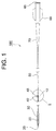
図1乃至図4に示す本実施形態のバルーンカテーテル100は、経皮的冠状動脈血管形成術(PTCA)などに使用される。
このバルーンカテーテル100は、熱可塑性樹脂からなるアウターシャフト10と、アウターシャフト10の先端に装着され、アウターシャフト10に形成されている拡張ルーメン10Lを流通する液体によって拡張するバルーン20と、アウターシャフト10に対して融着不能な熱可塑性樹脂からなる内層31と、当該アウターシャフト10に対して融着可能な熱可塑性樹脂からなる外層32とを備え、アウターシャフト10の内部およびバルーン20の内部に挿通されて、ガイドワイヤを挿通するためのガイドワイヤルーメン30Lを形成し(ガイドワイヤシャフトを構成し)、その先端部がバルーン20の先端部に固定され、その先端がガイドワイヤポート35として開口するインナーシャフト30と、アウターシャフト10およびインナーシャフト30の外層32に対して融着可能な熱可塑性樹脂からなり、インナーシャフト30の基端側に接続されて、当該インナーシャフト30とともにガイドワイヤルーメン30Lを形成し(ガイドワイヤシャフトを構成し)、その基端がガイドワイヤポート45として開口する接続チューブ40とを備えている。
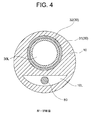
図1において、50は、アウターシャフト10の基端側に接続されたハイポチューブ、60は、ハイポチューブ50の基端側に装着されたハブ、70はストレインリリーフである。また、図2乃至図4において、80は、アウターシャフト10に形成されている拡張ルーメン10Lに挿入されているコアワイヤである。
The
The
In FIG. 1, 50 is a hypotube connected to the base end side of the
バルーンカテーテル100を構成するアウターシャフト10には、バルーン20を拡張させるための流体を流通する拡張ルーメン10Lが形成されている。
アウターシャフト10の外径としては0.7〜1.0mmであることが好ましく、好適な一例を示せば0.85mmである。
アウターシャフト10の長さは150〜450mmであることが好ましく、好適な一例を示せば390mmである。
An
The outer diameter of the
The length of the
アウターシャフト10の構成材料としては、ポリアミド、ポリエーテルポリアミド、ポリウレタン、ポリエーテルブロックアミド(PEBAX)(登録商標)およびナイロンなどの熱可塑性樹脂を挙げることができ、これらのうちPEBAXが好ましい。
アウターシャフト10の硬度としては、D型硬度計による硬度で63〜80であることが好ましい。
Examples of the constituent material of the
The hardness of the
アウターシャフト10の先端にはバルーン20が装着されている。
バルーン20は、アウターシャフト10の拡張ルーメン10Lを流通する液体によって拡張する。ここに、液体としては、生理食塩水を挙げることができる。
拡張時におけるバルーン20の直径としては1.0〜5.0mmであることが好ましい。
バルーン20の長さとしては5〜40mmであることが好ましい。
A
The
The diameter of the
The length of the
バルーン20の構成材料としては、従来公知のバルーンカテーテルを構成するバルーンと同一のものを使用することができ、好適な材料としてPEBAXを挙げることができる。バルーン20の構成材料の強度としては、曲げ弾性率が680Mpa〜780Mpaであることが好ましい。強度が低過ぎる場合には、過膨張になりやすく、皺の発生などを招きやすい。
As the constituent material of the
アウターシャフト10の内部およびバルーン20の内部には、インナーシャフト30が挿通されており、インナーシャフト30は、ガイドワイヤシャフトとしてガイドワイヤを挿通するためのガイドワイヤルーメン30Lを形成している。
インナーシャフト30の先端部は、バルーン20の先端部に固定されており、インナーシャフト30の先端には、ガイドワイヤポート35としての開口が形成されている。
一方、図3に示すように、インナーシャフト30の基端部は、アウターシャフト10の構成樹脂によって外周が覆われた状態で、アウターシャフト10に固定(熱融着)されている。
An
The distal end portion of the
On the other hand, as shown in FIG. 3, the base end portion of the
インナーシャフト30は、アウターシャフト10に対して融着不能な熱可塑性樹脂からなる内層31と、アウターシャフト10に対して融着可能な熱可塑性樹脂からなる外層32とにより構成されている。
The
インナーシャフト30の外径としては0.48〜0.60mmであることが好ましい。また、インナーシャフト30の内径としては0.35〜0.45mmであることが好ましい。
内層31の厚さとしては0.005〜0.030mmであることが好ましい。
外層32の厚さとしては0.01〜0.10mmであることが好ましい。
The outer diameter of the
The thickness of the
The thickness of the
内層31の構成材料としては、摩擦係数の低い潤滑性の良好な樹脂であることが好ましく、具体的には、ポリエチレンなどのポリオレフィン、PFA、PTFEなどのフッ素系樹脂を挙げることができ、これらのうち、ポリエチレンが好ましい。
外層32の構成材料としては、アウターシャフト10を構成するものとして例示した熱可塑性樹脂を挙げることができ、それらのうち、PEBAXが好ましい。
インナーシャフト30(外層32)の硬度としては、ガイドワイヤシャフトとしての剛性を確保する観点から、D型硬度計による硬度で55以上であることが好ましい。
The constituent material of the
As a constituent material of the
The hardness of the inner shaft 30 (outer layer 32) is preferably 55 or more as measured by a D-type hardness meter from the viewpoint of ensuring the rigidity as a guide wire shaft.
図3に示すように、インナーシャフト30の基端側には、接続チューブ40が接続固定(熱融着)されている。
この接続チューブ40は、インナーシャフト30とともに、ガイドワイヤルーメン30Lを形成している。すなわち、本実施形態のバルーンカテーテル100においては、インナーシャフト30と接続チューブ40とによってガイドワイヤシャフトが構成され、接続チューブ40の基端には、ガイドワイヤポート45としての開口が形成されている。
As shown in FIG. 3, the
The
接続チューブ40の外径および内径は、それぞれ、インナーシャフト30の外径および内径と同程度とされる。
接続チューブ40の長さ(L40)は1〜5mmであることが好ましい。
この長さ(L40)が短すぎる場合には、本発明の目的を十分に達成することができない。他方、この長さ(L40)が長すぎる場合には、ガイドワイヤルーメン30Lの潤滑性が損なわれることがある。
The outer diameter and inner diameter of the
The length (L40) of the
When this length (L40) is too short, the object of the present invention cannot be sufficiently achieved. On the other hand, when this length (L40) is too long, the lubricity of the
接続チューブ40は、アウターシャフト10およびインナーシャフト30の外層32に対して融着可能な熱可塑性樹脂からなる単層構成のチューブである。
接続チューブ40の構成材料としては、アウターシャフト10を構成するものとして例示した熱可塑性樹脂を挙げることができ、それらのうちPEBAXおよびナイロンが好ましい。
接続チューブ40の硬度としては、ガイドワイヤシャフトとしての剛性を確保する観点から、D型硬度計による硬度で70以上、特に72以上であることが好ましい。
The
Examples of the constituent material of the
The hardness of the
本実施形態のバルーンカテーテル100を構成する金属製のハイポチューブ50は、その先端部がアウターシャフト10の基端部に挿入され、その基端部がストレインリリーフ70およびハブ60に挿入されている。
ハイポチューブ50は、ステンレス、Ni−Ti、Cu−Mn−Al系合金などから構成され、その先端部分に螺旋状のスリットが形成されていてもよい。
ハイポチューブ50の長さは、通常900〜1500mmとされる。
The metal hypotube 50 constituting the
The
The length of the
ハイポチューブ50に装着されたハブ60の基端部には、バルーン20を拡張させるための流体を導入するための開口(バルーン拡張用ポート65)が形成されている。
このハブ60にはインディフレータが装着され、このインディフレータによってバルーンを拡張させるための圧力が調整される。
An opening (balloon expansion port 65) for introducing a fluid for expanding the
An inflator is attached to the
本実施形態のバルーンカテーテル100の推奨拡張圧(NP)としては8atm以上であることが好ましく、更に好ましくは10〜14atmである。
また、最大拡張圧(RBP)としては18atm以上であることが好ましく、更に好ましくは20〜25atmである。
このような高耐圧の仕様において、本発明のバルーンカテーテルは効果的である。
The recommended expansion pressure (NP) of the
The maximum expansion pressure (RBP) is preferably 18 atm or more, and more preferably 20 to 25 atm.
In such a high pressure resistant specification, the balloon catheter of the present invention is effective.
本実施形態のバルーンカテーテル100は、これを構成するシャフトを形成するためのチューブを熱融着することにより製造することができる。
具体的には、図5および図6に示すように、アウターシャフト10の先端側を形成するための第1チューブ10Aと、アウターシャフト10の基端側を形成するための第2チューブ10Bと、インナーシャフト30を形成するための第3チューブ30Aと、接続チューブ40を形成するための第4チューブ40Aとを配置し、第3チューブ30Aのルーメンおよび第4チューブ40Aのルーメンにマンドレル90(ガイドワイヤルーメンを確保するためのマンドレル)を挿通するとともに、第1チューブ10Aのルーメンおよび第2チューブ10Bのルーメンに、拡張ルーメンを確保するためのマンドレル(図示省略)を挿通する。
The
Specifically, as shown in FIGS. 5 and 6, a
図6に示すように、第1チューブ10Aと第2チューブ10Bとは、前者の基端部分の管壁に形成したスリットに、後者の先端部分の管壁を挿入することにより嵌合している。また、第2チューブ10Bの外側に配置した第3チューブ30Aは、第1チューブ10Aの内部に挿入されている。また、第3チューブ30Aの基端側には、第4チューブ40Aを配置している。
As shown in FIG. 6, the
このように配置された第1チューブ10A、第2チューブ10B、第3チューブ30Aおよび第4チューブ40Aに収縮チューブを被せて、この収縮チューブを介して加熱加圧することにより、これらのチューブが互いに熱融着されて固定される。その後、ガイドワイヤルーメンを確保するためのマンドレル90および拡張ルーメンを確保するためのマンドレルを抜去することにより、図2乃至図4に示したような構造部分を有するバルーンカテーテルを得ることができる。
The
上記の融着工程において、アウターシャフト10を形成するための第1チューブ10Aおよび第2チューブ10Bと、インナーシャフト30を形成するための第3チューブ30Aとを確実に熱融着させるために、図6において点線で囲まれた領域Mが集中的に加熱され、この結果、当該領域に位置する熱可塑性樹脂、特に、第3チューブ30Aの基端部分を構成する熱可塑性樹脂(内層31Aの構成樹脂および外層32Aの構成樹脂)が完全に溶融する。
In the above fusion process, the
他方、第3チューブ30Aの基端側に配置されている第4チューブ40Aの大部分は、集中的に加熱される前記領域Mから基端方向にある程度離間した位置にあるために、融着工程において、第4チューブ40Aの先端部分を構成する熱可塑性樹脂が僅かに溶融して第1チューブ10A、第2チューブ10Bおよび第3チューブ30Aと熱融着するものの、第4チューブ40Aを構成する熱可塑性樹脂の殆どが基端側に流れ出すことなく、第3チューブ30Aの基端側において接続固定(熱融着)される。
On the other hand, most of the
これにより、融着工程において、第3チューブ30Aの基端部分を構成する熱可塑性樹脂が溶融して基端側に流れ出そうとしても、その流れは、第4チューブ40Aによって阻止される。この結果、第3チューブ30Aを構成する樹脂が流れ出すことに起因するインナーシャフトの壁厚の減少(薄肉化)が抑制されて、当該インナーシャフト30は、所期の壁厚を維持することができる。
Thereby, even if the thermoplastic resin constituting the base end portion of the
また、融着工程において、マンドレル90の外周面と接触する第3チューブ30Aの内層31Aは、互いに熱融着される第3チューブ30Aの外層32Aと第4チューブ40Aとによって覆われているので、第3チューブ30Aの内層31Aの構成樹脂が基端側に流れ出すことは不可能である。
これにより、内層32Aの構成樹脂に由来する羽根状の小片(バリ)が、第4チューブ40Aによって形成される接続チューブ40の開口(ガイドワイヤポート45)の近傍に形成されるようなことはない。従って、これらの小片(バリ)を除去する作業が不要となり、製造効率等の観点からもきわめて有利である。
Further, in the fusion process, the
Thereby, a blade-like small piece (burr) derived from the constituent resin of the
本実施形態のバルーンカテーテル100によれば、従来のバルーンカテーテルにおいて問題であった、第3チューブ30Aの構成樹脂が基端側に流れ出すことに起因するインナーシャフトの壁厚の減少(薄肉化)が抑制されて、当該インナーシャフト30は、所期の壁厚を維持することができる。
そして、インナーシャフト30の壁厚が維持されることによって当該シャフトの剛性が確保される結果、本実施形態のバルーンカテーテル100の使用時(バルーン20の拡張時)において、従来のバルーンカテーテルにおいて問題であった、バルーンを拡張させる液体の圧力によってインナーシャフトが潰れてガイドワイヤルーメンが狭窄することはなく、従って、ガイドワイヤのスタックが生じることはない。
また、従来のバルーンカテーテルにおいて問題であった羽根状の小片(バリ)を、第4チューブ40Aにより形成される接続チューブ40の開口であるガイドワイヤポート45の近傍に生じさせるようなことはない。
According to the
As a result of maintaining the rigidity of the shaft by maintaining the wall thickness of the
Further, a blade-like small piece (burr), which is a problem in the conventional balloon catheter, is not generated in the vicinity of the
以上、本発明の一実施形態について説明したが、本発明はこれらに限定されるものではなく、種々の変更が可能である。
例えば、インナーシャフトの外層や接続チューブが複数の層から形成されていてもよい。
As mentioned above, although one Embodiment of this invention was described, this invention is not limited to these, A various change is possible.
For example, the outer layer of the inner shaft and the connection tube may be formed from a plurality of layers.
100 バルーンカテーテル
10 アウターシャフト
10L 拡張ルーメン
20 バルーン
30 インナーシャフト
30L ガイドワイヤルーメン
31 内層
32 外層
35 ガイドワイヤポート
40 接続チューブ
45 ガイドワイヤポート
50 ハイポチューブ
60 ハブ
65 バルーン拡張用ポート
70 ストレインリリーフ
80 コアワイヤ 90 マンドレル
10A 第1チューブ
10B 第2チューブ
30A 第3チューブ
31A 内層
32A 外層
40A 第4チューブ
DESCRIPTION OF
10B
Claims (5)
前記アウターシャフトの先端に装着され、当該アウターシャフトに形成されている拡張ルーメンを流通する液体によって拡張するバルーンと、
前記アウターシャフトに対して融着不能な熱可塑性樹脂からなる内層と、当該アウターシャフトに対して融着可能な熱可塑性樹脂からなる外層とを備え、前記アウターシャフトの内部および前記バルーンの内部に挿通されて、ガイドワイヤを挿通するためのガイドワイヤルーメンを形成し、その先端部が前記バルーンの先端部に固定され、その先端がガイドワイヤポートとして開口するインナーシャフトと、
前記アウターシャフトおよび前記インナーシャフトの外層に対して融着可能な熱可塑性樹脂からなり、前記インナーシャフトの基端に接続されて、当該インナーシャフトとともにガイドワイヤルーメンを形成し、前記アウターシャフトに直接接続され、その基端が、ガイドワイヤポートとして前記アウターシャフトの側面において開口する単層構成の接続チューブとを備えていることを特徴とするバルーンカテーテル。 An outer shaft made of thermoplastic resin;
A balloon that is attached to the tip of the outer shaft and expands with a liquid flowing through an expansion lumen formed in the outer shaft;
An inner layer made of a thermoplastic resin that cannot be fused to the outer shaft; and an outer layer made of a thermoplastic resin that can be fused to the outer shaft, and is inserted into the outer shaft and the balloon. An inner shaft that forms a guide wire lumen for inserting a guide wire, the distal end of which is fixed to the distal end of the balloon, and the distal end of which opens as a guide wire port;
It is made of a thermoplastic resin that can be fused to the outer layer of the outer shaft and the inner shaft, and is connected to the base end of the inner shaft to form a guide wire lumen together with the inner shaft and directly connected to the outer shaft A balloon catheter characterized in that a proximal end of the balloon catheter includes a single-layer connection tube that opens as a guide wire port on a side surface of the outer shaft .
前記アウターシャフトの基端側を形成するために前記第1チューブの基端側に配置された第2チューブと、
前記内層と前記外層とを備えてなり、前記インナーシャフトを形成するために前記第1チューブの内部に挿入された第3チューブと、
前記接続チューブを形成するために前記第3チューブの基端側に配置された単層構成の第4チューブとが熱融着されてなることを特徴とする請求項1に記載のバルーンカテーテル。 A first tube for forming a distal end side of the outer shaft;
A second tube disposed on the base end side of the first tube to form a base end side of the outer shaft;
A third tube comprising the inner layer and the outer layer, and inserted into the first tube to form the inner shaft;
2. The balloon catheter according to claim 1, wherein a fourth tube having a single-layer structure disposed on a proximal end side of the third tube is heat-sealed to form the connection tube.
前記インナーシャフトの内層を構成する熱可塑性樹脂がポリオレフィンまたはフッ素系樹脂であることを特徴とする請求項1または請求項2に記載のバルーンカテーテル。 The outer shaft, the outer layer of the inner shaft, and the thermoplastic resin constituting the connection tube are at least one selected from polyamide, polyether polyamide, polyurethane, polyether block amide, and nylon,
The balloon catheter according to claim 1 or 2, wherein the thermoplastic resin constituting the inner layer of the inner shaft is a polyolefin or a fluorine resin.
前記インナーシャフトの内層を構成する熱可塑性樹脂がポリエチレンであることを特徴とする請求項1または請求項2に記載のバルーンカテーテル。 The outer shaft, the outer layer of the inner shaft, and the thermoplastic resin constituting the connection tube is polyether block amide or nylon,
The balloon catheter according to claim 1 or 2, wherein the thermoplastic resin constituting the inner layer of the inner shaft is polyethylene.
Priority Applications (3)
| Application Number | Priority Date | Filing Date | Title |
|---|---|---|---|
| JP2013071506A JP6164638B2 (en) | 2013-03-29 | 2013-03-29 | Balloon catheter |
| PCT/JP2014/056246 WO2014156600A1 (en) | 2013-03-29 | 2014-03-11 | Balloon catheter |
| TW103111240A TWI637757B (en) | 2013-03-29 | 2014-03-26 | Balloon catheter |
Applications Claiming Priority (1)
| Application Number | Priority Date | Filing Date | Title |
|---|---|---|---|
| JP2013071506A JP6164638B2 (en) | 2013-03-29 | 2013-03-29 | Balloon catheter |
Publications (3)
| Publication Number | Publication Date |
|---|---|
| JP2014195487A JP2014195487A (en) | 2014-10-16 |
| JP2014195487A5 JP2014195487A5 (en) | 2015-11-12 |
| JP6164638B2 true JP6164638B2 (en) | 2017-07-19 |
Family
ID=51623583
Family Applications (1)
| Application Number | Title | Priority Date | Filing Date |
|---|---|---|---|
| JP2013071506A Active JP6164638B2 (en) | 2013-03-29 | 2013-03-29 | Balloon catheter |
Country Status (3)
| Country | Link |
|---|---|
| JP (1) | JP6164638B2 (en) |
| TW (1) | TWI637757B (en) |
| WO (1) | WO2014156600A1 (en) |
Families Citing this family (10)
| Publication number | Priority date | Publication date | Assignee | Title |
|---|---|---|---|---|
| JP6304886B2 (en) * | 2014-10-28 | 2018-04-04 | 日本ライフライン株式会社 | Balloon catheter |
| JP2018019729A (en) * | 2014-12-15 | 2018-02-08 | テルモ株式会社 | Balloon catheter |
| EP3272384A4 (en) | 2015-03-20 | 2018-11-14 | Terumo Kabushiki Kaisha | Catheter and catheter manufacturing method |
| WO2017057390A1 (en) * | 2015-09-29 | 2017-04-06 | テルモ株式会社 | Balloon catheter, and method of producing long member for balloon catheter |
| JP6831366B2 (en) | 2016-03-16 | 2021-02-17 | テルモ株式会社 | Method for manufacturing balloon catheter and long member for balloon catheter |
| WO2018181312A1 (en) * | 2017-03-28 | 2018-10-04 | テルモ株式会社 | Balloon catheter and method for manufacturing medical elongated body |
| WO2018212126A1 (en) * | 2017-05-15 | 2018-11-22 | テルモ株式会社 | Balloon catheter and method for manufacturing balloon catheter |
| CN110944707B (en) * | 2017-05-23 | 2022-11-04 | 波士顿科学医学有限公司 | Cryogenic balloon for intravascular catheter systems |
| US11612720B2 (en) * | 2019-09-13 | 2023-03-28 | Creganna Unlimited Company | Exit path connector for catheter assembly |
| WO2022138813A1 (en) * | 2020-12-25 | 2022-06-30 | テルモ株式会社 | Medical instrument and method for manufacturing medical instrument |
Family Cites Families (6)
| Publication number | Priority date | Publication date | Assignee | Title |
|---|---|---|---|---|
| JP4913963B2 (en) * | 2001-08-30 | 2012-04-11 | 川澄化学工業株式会社 | Balloon catheter |
| US8382738B2 (en) * | 2006-06-30 | 2013-02-26 | Abbott Cardiovascular Systems, Inc. | Balloon catheter tapered shaft having high strength and flexibility and method of making same |
| US7906066B2 (en) * | 2006-06-30 | 2011-03-15 | Abbott Cardiovascular Systems, Inc. | Method of making a balloon catheter shaft having high strength and flexibility |
| CA2660942A1 (en) * | 2006-09-13 | 2008-03-20 | Boston Scientific Limited | Balloon catheter |
| JP2012042619A (en) * | 2010-08-17 | 2012-03-01 | Canon Inc | Lens barrel |
| WO2012042619A1 (en) * | 2010-09-29 | 2012-04-05 | 株式会社グッドマン | Catheter and production method therefor |
-
2013
- 2013-03-29 JP JP2013071506A patent/JP6164638B2/en active Active
-
2014
- 2014-03-11 WO PCT/JP2014/056246 patent/WO2014156600A1/en active Application Filing
- 2014-03-26 TW TW103111240A patent/TWI637757B/en not_active IP Right Cessation
Also Published As
| Publication number | Publication date |
|---|---|
| TW201507741A (en) | 2015-03-01 |
| TWI637757B (en) | 2018-10-11 |
| JP2014195487A (en) | 2014-10-16 |
| WO2014156600A1 (en) | 2014-10-02 |
Similar Documents
| Publication | Publication Date | Title |
|---|---|---|
| JP6164638B2 (en) | Balloon catheter | |
| JP4535868B2 (en) | catheter | |
| JP5469680B2 (en) | Catheter with skive-like tubular member | |
| US9339632B2 (en) | Catheter shaft designs | |
| JP6348486B2 (en) | Balloon catheter and method for manufacturing balloon catheter | |
| JPWO2017110757A1 (en) | Balloon catheter and medical elongated body | |
| JP2010220760A (en) | Balloon catheter and method of manufacturing the same | |
| JP5497068B2 (en) | catheter | |
| JP2002301161A (en) | Catheter and manufacturing method for catheter | |
| JP5580279B2 (en) | Balloon catheter | |
| JP6528463B2 (en) | CATHETER AND METHOD OF MANUFACTURING THE SAME | |
| EP2805742B1 (en) | Balloon catheter | |
| JP2005211308A (en) | Catheter and manufacturing method thereof | |
| JP5709077B2 (en) | Catheter, balloon catheter, and stent delivery catheter | |
| JP4254200B2 (en) | Balloon catheter and manufacturing method thereof | |
| JP6804802B2 (en) | Balloon catheter | |
| JP6363922B2 (en) | catheter | |
| JP2002239009A (en) | Balloon catheter and method of manufacturing balloon catheter | |
| JP6388316B2 (en) | Balloon catheter | |
| WO2016152666A1 (en) | Catheter and catheter manufacturing method | |
| JP6044990B2 (en) | Catheter balloon and balloon catheter | |
| JP2004121276A (en) | Balloon catheter and production method therefor |
Legal Events
| Date | Code | Title | Description |
|---|---|---|---|
| A521 | Request for written amendment filed |
Free format text: JAPANESE INTERMEDIATE CODE: A523 Effective date: 20150924 |
|
| A621 | Written request for application examination |
Free format text: JAPANESE INTERMEDIATE CODE: A621 Effective date: 20150924 |
|
| A131 | Notification of reasons for refusal |
Free format text: JAPANESE INTERMEDIATE CODE: A131 Effective date: 20160620 |
|
| A521 | Request for written amendment filed |
Free format text: JAPANESE INTERMEDIATE CODE: A523 Effective date: 20160728 |
|
| A131 | Notification of reasons for refusal |
Free format text: JAPANESE INTERMEDIATE CODE: A131 Effective date: 20161202 |
|
| A521 | Request for written amendment filed |
Free format text: JAPANESE INTERMEDIATE CODE: A523 Effective date: 20170116 |
|
| TRDD | Decision of grant or rejection written | ||
| A01 | Written decision to grant a patent or to grant a registration (utility model) |
Free format text: JAPANESE INTERMEDIATE CODE: A01 Effective date: 20170614 |
|
| A61 | First payment of annual fees (during grant procedure) |
Free format text: JAPANESE INTERMEDIATE CODE: A61 Effective date: 20170614 |
|
| R150 | Certificate of patent or registration of utility model |
Ref document number: 6164638 Country of ref document: JP Free format text: JAPANESE INTERMEDIATE CODE: R150 |
|
| R250 | Receipt of annual fees |
Free format text: JAPANESE INTERMEDIATE CODE: R250 |
|
| R250 | Receipt of annual fees |
Free format text: JAPANESE INTERMEDIATE CODE: R250 |
|
| R250 | Receipt of annual fees |
Free format text: JAPANESE INTERMEDIATE CODE: R250 |
|
| R250 | Receipt of annual fees |
Free format text: JAPANESE INTERMEDIATE CODE: R250 |