JP6164045B2 - Vehicle braking force control method - Google Patents
Vehicle braking force control method Download PDFInfo
- Publication number
- JP6164045B2 JP6164045B2 JP2013225717A JP2013225717A JP6164045B2 JP 6164045 B2 JP6164045 B2 JP 6164045B2 JP 2013225717 A JP2013225717 A JP 2013225717A JP 2013225717 A JP2013225717 A JP 2013225717A JP 6164045 B2 JP6164045 B2 JP 6164045B2
- Authority
- JP
- Japan
- Prior art keywords
- braking force
- front wheels
- target
- friction
- front wheel
- Prior art date
- Legal status (The legal status is an assumption and is not a legal conclusion. Google has not performed a legal analysis and makes no representation as to the accuracy of the status listed.)
- Expired - Fee Related
Links
- 238000000034 method Methods 0.000 title claims description 18
- 230000001172 regenerating effect Effects 0.000 claims description 195
- 230000003247 decreasing effect Effects 0.000 claims description 6
- 230000008929 regeneration Effects 0.000 claims 1
- 238000011069 regeneration method Methods 0.000 claims 1
- 230000007423 decrease Effects 0.000 description 13
- 230000008859 change Effects 0.000 description 12
- 230000005540 biological transmission Effects 0.000 description 5
- 230000009467 reduction Effects 0.000 description 5
- 238000007796 conventional method Methods 0.000 description 2
- 238000010586 diagram Methods 0.000 description 2
- 238000002474 experimental method Methods 0.000 description 2
- 230000004043 responsiveness Effects 0.000 description 2
- 230000005856 abnormality Effects 0.000 description 1
- 230000000694 effects Effects 0.000 description 1
- 238000005516 engineering process Methods 0.000 description 1
- 230000008569 process Effects 0.000 description 1
- 230000004044 response Effects 0.000 description 1
Images


Classifications
-
- B—PERFORMING OPERATIONS; TRANSPORTING
- B60—VEHICLES IN GENERAL
- B60L—PROPULSION OF ELECTRICALLY-PROPELLED VEHICLES; SUPPLYING ELECTRIC POWER FOR AUXILIARY EQUIPMENT OF ELECTRICALLY-PROPELLED VEHICLES; ELECTRODYNAMIC BRAKE SYSTEMS FOR VEHICLES IN GENERAL; MAGNETIC SUSPENSION OR LEVITATION FOR VEHICLES; MONITORING OPERATING VARIABLES OF ELECTRICALLY-PROPELLED VEHICLES; ELECTRIC SAFETY DEVICES FOR ELECTRICALLY-PROPELLED VEHICLES
- B60L7/00—Electrodynamic brake systems for vehicles in general
- B60L7/24—Electrodynamic brake systems for vehicles in general with additional mechanical or electromagnetic braking
- B60L7/26—Controlling the braking effect
-
- B—PERFORMING OPERATIONS; TRANSPORTING
- B60—VEHICLES IN GENERAL
- B60T—VEHICLE BRAKE CONTROL SYSTEMS OR PARTS THEREOF; BRAKE CONTROL SYSTEMS OR PARTS THEREOF, IN GENERAL; ARRANGEMENT OF BRAKING ELEMENTS ON VEHICLES IN GENERAL; PORTABLE DEVICES FOR PREVENTING UNWANTED MOVEMENT OF VEHICLES; VEHICLE MODIFICATIONS TO FACILITATE COOLING OF BRAKES
- B60T1/00—Arrangements of braking elements, i.e. of those parts where braking effect occurs specially for vehicles
- B60T1/02—Arrangements of braking elements, i.e. of those parts where braking effect occurs specially for vehicles acting by retarding wheels
- B60T1/10—Arrangements of braking elements, i.e. of those parts where braking effect occurs specially for vehicles acting by retarding wheels by utilising wheel movement for accumulating energy, e.g. driving air compressors
-
- B—PERFORMING OPERATIONS; TRANSPORTING
- B60—VEHICLES IN GENERAL
- B60T—VEHICLE BRAKE CONTROL SYSTEMS OR PARTS THEREOF; BRAKE CONTROL SYSTEMS OR PARTS THEREOF, IN GENERAL; ARRANGEMENT OF BRAKING ELEMENTS ON VEHICLES IN GENERAL; PORTABLE DEVICES FOR PREVENTING UNWANTED MOVEMENT OF VEHICLES; VEHICLE MODIFICATIONS TO FACILITATE COOLING OF BRAKES
- B60T8/00—Arrangements for adjusting wheel-braking force to meet varying vehicular or ground-surface conditions, e.g. limiting or varying distribution of braking force
- B60T8/17—Using electrical or electronic regulation means to control braking
- B60T8/176—Brake regulation specially adapted to prevent excessive wheel slip during vehicle deceleration, e.g. ABS
- B60T8/1761—Brake regulation specially adapted to prevent excessive wheel slip during vehicle deceleration, e.g. ABS responsive to wheel or brake dynamics, e.g. wheel slip, wheel acceleration or rate of change of brake fluid pressure
- B60T8/17616—Microprocessor-based systems
-
- B—PERFORMING OPERATIONS; TRANSPORTING
- B60—VEHICLES IN GENERAL
- B60T—VEHICLE BRAKE CONTROL SYSTEMS OR PARTS THEREOF; BRAKE CONTROL SYSTEMS OR PARTS THEREOF, IN GENERAL; ARRANGEMENT OF BRAKING ELEMENTS ON VEHICLES IN GENERAL; PORTABLE DEVICES FOR PREVENTING UNWANTED MOVEMENT OF VEHICLES; VEHICLE MODIFICATIONS TO FACILITATE COOLING OF BRAKES
- B60T2270/00—Further aspects of brake control systems not otherwise provided for
- B60T2270/60—Regenerative braking
- B60T2270/602—ABS features related thereto
Landscapes
- Engineering & Computer Science (AREA)
- Mechanical Engineering (AREA)
- Transportation (AREA)
- Physics & Mathematics (AREA)
- Fluid Mechanics (AREA)
- Microelectronics & Electronic Packaging (AREA)
- Combustion & Propulsion (AREA)
- Chemical & Material Sciences (AREA)
- Electromagnetism (AREA)
- Power Engineering (AREA)
- Regulating Braking Force (AREA)
- Electric Propulsion And Braking For Vehicles (AREA)
- Hybrid Electric Vehicles (AREA)
Description
本発明は、車両操舵輪である前輪に回生制動力及び摩擦制動力が付与される車両の制動力制御方法に係る。 The present invention relates to a vehicle braking force control method in which a regenerative braking force and a friction braking force are applied to a front wheel that is a vehicle steering wheel.
回生制動が行われる車両に於いては、回生制動力が付与されている車輪の制動スリップが過大になると、アンチスキッド制御(ABS制御)による制動力の制御の開始に先立って、いわゆる「制動力のすり替え」が行われる。すなわち、回生制動力が0になるまで漸減されると共に摩擦制動力が漸増されることにより、回生制動力が摩擦制動力にすり替えられる。そして、制動力のすり替えが完了した後に、アンチスキッド制御の開始条件が成立すると、アンチスキッド制御によって摩擦制動力が車輪の制動スリップに応じて増減されることにより、制動スリップが低減される。 In a vehicle in which regenerative braking is performed, if the braking slip of the wheel to which the regenerative braking force is applied becomes excessive, the so-called “braking force” is started prior to the start of braking force control by anti-skid control (ABS control). "Replacement" is performed. In other words, the regenerative braking force is gradually reduced until the regenerative braking force becomes zero and the friction braking force is gradually increased, whereby the regenerative braking force is replaced with the friction braking force. When the anti-skid control start condition is satisfied after the replacement of the braking force is completed, the friction braking force is increased or decreased according to the braking slip of the wheel by the anti-skid control, thereby reducing the braking slip.
この制動力のすり替えにおいて、摩擦制動力が0より増大される場合には、摩擦制動力の増大指令が出力されても、摩擦制動力はすぐには増大せず、摩擦制動力の増大率は増大指令の増大率よりも低くなる。その要因として、ブレーキアクチュエータによりホイールシリンダへのブレーキオイルの供給が開始されても、ホイールシリンダ内の圧力が実際に上昇するまでに時間を要すること、ブレーキアクチュエータに応答遅れがあること、ノックバック等がある。 In this replacement of the braking force, if the friction braking force is increased from 0, even if a friction braking force increase command is output, the friction braking force does not increase immediately, and the rate of increase of the friction braking force is It becomes lower than the increase rate of the increase command. As a factor, even if the brake oil supply to the wheel cylinder is started by the brake actuator, it takes time until the pressure in the wheel cylinder actually rises, there is a response delay in the brake actuator, knockback, etc. There is.
制動力のすり替え時における摩擦制動力の増大遅れに起因して車両全体の制動力が低下すると、車両の減速度が低下するため、車両の乗員は違和感を覚える。この問題に対処すべく、例えば下記の特許文献1には、摩擦制動力の増大遅れに起因する制動力の不足分を回生制動力にて補填することが提案されている。特許文献1に記載された構成によれば、制動力のすり替え時に車両全体の制動力が不足する虞れ及びその制動力の不足に起因して車両の減速度が低下する虞れを低減することができる。 When the braking force of the entire vehicle decreases due to the delay in the increase of the friction braking force when the braking force is replaced, the vehicle deceleration decreases, so the vehicle occupant feels uncomfortable. In order to cope with this problem, for example, Japanese Patent Application Laid-Open No. H10-228707 proposes to compensate for the shortage of the braking force due to the delay in the increase of the friction braking force with the regenerative braking force. According to the configuration described in Patent Document 1, it is possible to reduce the possibility that the braking force of the entire vehicle is insufficient when the braking force is replaced, and the possibility that the deceleration of the vehicle is reduced due to the insufficient braking force. Can do.
〔発明が解決しようとする課題〕
上記特許文献1においては、制動力のすり替えは、車両の停止直前の車速低下時に行われるよう説明されているが、アンチスキッド制御による制動力の制御に備えて上記特許文献1に記載された制動力のすり替えを行うことが考えられる。
[Problems to be Solved by the Invention]
In the above-mentioned Patent Document 1, it is described that the replacement of the braking force is performed when the vehicle speed decreases immediately before the vehicle stops. However, in preparation for the control of the braking force by the anti-skid control, the braking force described in the Patent Document 1 is described. It is conceivable to change the power.
しかし、操舵輪である前輪に回生制動力が付与され、車両が旋回している状況において、アンチスキッド制御に備えて上記制動力のすり替えが行われると、前輪の制動力が低減されないため、前輪の横力不足に起因して車両がアンダーステア状態になることがある。特に、前輪の制動スリップ量が大きくその増大率が大きいほど、車両がアンダーステア状態になり易い。 However, in the situation where regenerative braking force is applied to the front wheels that are the steering wheels and the vehicle is turning, if the braking force is replaced in preparation for anti-skid control, the braking force of the front wheels is not reduced. The vehicle may become understeered due to insufficient lateral force. In particular, the greater the braking slip amount of the front wheels and the greater the increase rate, the easier the vehicle is in an understeer state.
本発明は、回生制動力が操舵輪である前輪に付与されている状況においてアンチスキッド制御による制動力の制御に備えて制動力のすり替えが行われる場合における上述の如き問題に鑑みてなされたものである。そして本発明の主要な課題は、前輪に回生制動力が付与されている状況において制動力のすり替えが行われる場合に、車両の減速度が違和感を惹起すほどに低下する虞れを低減しつつ、車両がアンダーステア状態になる虞れを低減することである。
〔課題を解決するための手段及び発明の効果〕
The present invention has been made in view of the above-described problems when the braking force is replaced in preparation for the braking force control by the anti-skid control in the situation where the regenerative braking force is applied to the front wheel which is the steering wheel. It is. The main object of the present invention is to reduce the possibility that the deceleration of the vehicle will be lowered to the point of causing a sense of incongruity when the braking force is replaced in a situation where the regenerative braking force is applied to the front wheels. This is to reduce the possibility that the vehicle will be understeered.
[Means for Solving the Problems and Effects of the Invention]
上述の主要な課題は、本発明によれば、操舵輪である前輪に回生制動力及び摩擦制動力が付与される車両に適用され、前輪の目標制動力を演算し、該目標制動力に基づいて回生制動力及び摩擦制動力を制御する車両の制動力制御方法において、前輪に回生制動力が付与されている状況にて少なくとも一方の前輪の制動スリップの度合が基準値を越えると、当該時点を基準時点として、基準時点以降で前記基準時点より所定の時間が経過する時点以前においては、前輪の制動力が目標制動力よりも低い値になるよう、前記基準時点における前輪の回生制動力よりも所定値低い暫定の目標回生制動力になるように前輪の回生制動力を制御しつつ、前輪の摩擦制動力が漸次増大するように前輪の摩擦制動力を制御し、前記基準時点より所定の時間が経過した時点以降においては、前輪の制動力が目標制動力になるよう、前輪の回生制動力が漸次低下すると共に前輪の摩擦制動力が漸次増大するように、回生制動力を低下させる制御及び摩擦制動力を増大させる制御を行うことを特徴とする車両の制動力制御方法によって達成される。 According to the present invention, the main problem described above is applied to a vehicle in which a regenerative braking force and a friction braking force are applied to a front wheel that is a steered wheel, calculates a target braking force of the front wheel, and is based on the target braking force. In the vehicle braking force control method for controlling the regenerative braking force and friction braking force, when the degree of braking slip of at least one front wheel exceeds the reference value in a situation where the regenerative braking force is applied to the front wheel, From the regenerative braking force of the front wheels at the reference time point so that the braking force of the front wheels is lower than the target braking force before the time point when the predetermined time has elapsed from the reference time point. Also, while controlling the front wheel regenerative braking force so that the provisional target regenerative braking force is lower than the predetermined value, the front wheel friction braking force is controlled so that the front wheel friction braking force gradually increases. The time In the following the time spent, so that the front wheel braking force becomes the target braking force, so that the front wheel of the friction braking force with the front wheel of the regenerative braking force is gradually decreased gradually increases, control and friction reducing the regenerative braking force This is achieved by a vehicle braking force control method characterized by performing control to increase the braking force.
上記の構成によれば、少なくとも一方の前輪の制動スリップの度合が基準値を越えると、その時点(基準時点)以降で基準時点より所定の時間が経過する時点以前においては、前輪の制動力が目標制動力よりも低い値になるよう、基準時点における前輪の回生制動力よりも所定値低い暫定の目標回生制動力になるように前輪の回生制動力が制御され、その状況にて、前輪の摩擦制動力が漸次増大するように制御される。 According to the above configuration, when the degree of braking slip of at least one front wheel exceeds the reference value , the braking force of the front wheel is not increased until a predetermined time elapses from the reference time after that time (reference time). The regenerative braking force of the front wheels is controlled to be a provisional target regenerative braking force that is a predetermined value lower than the regenerative braking force of the front wheels at the reference time point so that the value is lower than the target braking force. The friction braking force is controlled to gradually increase.
よって、基準時点以降で基準時点より所定の時間が経過する時点以前においては、前輪の回生制動力が暫定の目標回生制動力になって前輪の制動力が目標制動力よりも低い値になるので、前輪の制動スリップの度合が増大することを抑制することができる。従って、車両が旋回していても、前輪の横力が不足することに起因して車両がアンダーステア状態になる虞れを低減することができる。 Therefore, before the point in time after the reference point and before a predetermined time elapses, the regenerative braking force of the front wheels becomes the provisional target regenerative braking force, and the braking force of the front wheels becomes lower than the target braking force. It is possible to suppress an increase in the degree of braking slip of the front wheels. Therefore, even if the vehicle is turning, it is possible to reduce the possibility that the vehicle will be understeered due to insufficient lateral force of the front wheels.
また、摩擦制動力は遅れを伴いながらも増大するので、前輪の制動力が目標制動力よりも低い状況が所定の時間を越えて過剰に長く継続することはない。従って、車両全体の制動力が過剰に長く低下することはないので、車両の減速度の低下に起因して車両の乗員が違和感を覚える虞れを低減することができる。 Further, since the friction braking force increases with a delay, the situation in which the braking force of the front wheels is lower than the target braking force does not continue excessively longer than a predetermined time . Accordingly, since the braking force of the entire vehicle does not decrease excessively long, it is possible to reduce the possibility that the vehicle occupant feels uncomfortable due to the decrease in the deceleration of the vehicle.
更に、制動力のすり替え時に摩擦制動力が0から増大される場合における摩擦制動力の増大遅れは、基準時点よりの経過時間が長くなるほど小さくなる。換言すれば、増大指令に対する摩擦制動力の増大の応答性は、基準時点よりの経過時間が長くなるほど高くなる。 Further, the increase in the friction braking force when the friction braking force is increased from 0 when the braking force is replaced becomes smaller as the elapsed time from the reference time becomes longer. In other words, the responsiveness of the increase in the friction braking force with respect to the increase command becomes higher as the elapsed time from the reference time becomes longer.
上記の構成によれば、基準時点より所定の時間が経過すると、前輪の制動力が目標制動力になるよう、前輪の回生制動力が漸次低下されると共に、前輪の摩擦制動力が漸次増大されることにより、回生制動力が漸次摩擦制動力にすり替えられる。よって、基準時点において制動力のすり替えが開始される場合に比して、増大指令に対する摩擦制動力の応答性が向上しているので、制動力のすり替えに必要とされる摩擦制動力の増大率と実際の摩擦制動力の増大率との差を小さくすることができる。従って、制動力のすり替えが行われる過程において、摩擦制動力の増大率が不足することに起因して前輪の制動力が目標制動力よりも低くなる虞れを低減することができる。 According to the above configuration, when a predetermined time has elapsed from the reference time point, the regenerative braking force of the front wheels is gradually decreased and the friction braking force of the front wheels is gradually increased so that the braking force of the front wheels becomes the target braking force. Thus, the regenerative braking force is gradually replaced with the friction braking force. Therefore, since the responsiveness of the friction braking force to the increase command is improved as compared with the case where the braking force replacement is started at the reference time, the increase rate of the friction braking force required for the braking force replacement is improved. And the actual rate of increase in friction braking force can be reduced. Therefore, it is possible to reduce the possibility that the braking force of the front wheels becomes lower than the target braking force due to the insufficient increase rate of the frictional braking force in the process of replacing the braking force.
また、本発明によれば、上記の構成において、前記所定値は、前記基準時点における前輪の目標制動力と、前輪の制動スリップの度合が増大することを抑制するための前輪の暫定の目標制動力との差であってよい。 Further, according to the present invention, in the above configuration, the predetermined value is a provisional target system for the front wheels for suppressing an increase in the target braking force of the front wheels at the reference time point and the degree of braking slip of the front wheels. It may be the difference from power.
上記の構成によれば、暫定の目標回生制動力は、前輪の制動スリップの度合が増大することを抑制するための前輪の暫定の目標制動力と基準時点における摩擦制動力との差である。よって、暫定の目標回生制動力になるように前輪の回生制動力を制御することにより、前輪の暫定の目標制動力になるよう、前輪の制動力を制御することができる。従って、前輪の制動スリップの度合が増大することを抑制することができるので、車両が旋回していても、前輪の横力が不足することに起因して車両がアンダーステア状態になる虞れを低減することができる。 According to the above configuration, the provisional target regenerative braking force is a difference between the provisional target braking force of the front wheels for suppressing an increase in the degree of braking slip of the front wheels and the friction braking force at the reference time point. Therefore, by controlling the regenerative braking force of the front wheels so as to become the provisional target regenerative braking force, the braking force of the front wheels can be controlled so as to become the provisional target braking force of the front wheels. Accordingly, it is possible to suppress an increase in the degree of braking slip of the front wheels, thereby reducing the possibility that the vehicle will be understeered due to insufficient lateral force of the front wheels even when the vehicle is turning. can do.
また、本発明によれば、上記の構成において、前記基準時点以降における前輪の摩擦制動力の増大量が前記所定値以上になったと判定したときに、前記基準時点より所定の時間が経過したと判定するようになっていてよい。 According to the present invention, in the above configuration, when it is determined that the amount of increase in the friction braking force of the front wheels after the reference time is equal to or greater than the predetermined value, a predetermined time has elapsed from the reference time. You may come to judge.
上記の構成によれば、基準時点以降における前輪の摩擦制動力の増大量が所定値以上になったと判定したときに、制動力のすり替え、すなわち、回生制動力の漸次低下及び摩擦制動力の漸次増大を開始させることができる。よって、制動力のすり替えに必要とされる摩擦制動力の増大率と制動力のすり替えが開始される際の摩擦制動力の増大率との差をできるだけ小さくすることができる。また、前輪の摩擦制動力の増大量が所定値になったと判定したときに、基準時点より所定の時間が経過したと判定し、すり替えを開始すれば、すり替えが開始されるまでに摩擦制動力が過剰に増大することを回避することができる。 According to the above configuration, when it is determined that the amount of increase in the friction braking force of the front wheels after the reference time has reached a predetermined value or more, the braking force is replaced, that is, the regenerative braking force gradually decreases and the friction braking force gradually increases. The increase can be started. Therefore, the difference between the increase rate of the friction braking force required for the replacement of the braking force and the increase rate of the friction braking force when the replacement of the braking force is started can be made as small as possible. Further, when it is determined that the amount of increase in the friction braking force of the front wheels has reached a predetermined value, it is determined that a predetermined time has elapsed from the reference time, and if replacement is started, the friction braking force is increased until the replacement is started. Can be avoided from increasing excessively.
また、本発明によれば、上記の構成において、前記所定の時間は予め設定された値であってよい。 According to the present invention, in the above configuration, the predetermined time may be a preset value.
上記の構成によれば、基準時点以降における前輪の摩擦制動力の増大量を求めたり、摩擦制動力の増大量が所定値以上になったか否かを判定したりする必要がない。よって、基準時点以降における前輪の摩擦制動力の増大量が所定値以上になったか否かが判定される場合に比して、制動力のすり替えを容易に行うことができる。なお、予め設定された値は、制動力のすり替えが開始されるまでに摩擦制動力の増大遅れが解消され、摩擦制動力の増大率ができるだけ必要とされる増大率に近くなると共に、すり替えが開始されるまでに摩擦制動力が過剰に増大することを防止できるよう、例えば実験により求められてよい。 According to the above configuration, it is not necessary to obtain the amount of increase in the friction braking force of the front wheels after the reference time point or to determine whether or not the amount of increase in the friction braking force has reached a predetermined value or more. Therefore, it is possible to easily replace the braking force as compared with the case where it is determined whether or not the increase amount of the friction braking force of the front wheels after the reference time has reached a predetermined value or more. It should be noted that the preset value eliminates the increase in the friction braking force until the braking force replacement is started, and the increase rate of the friction braking force is as close to the required increase rate as possible. It may be determined, for example, by experiment so as to prevent the frictional braking force from increasing excessively before it is started.
また、本発明によれば、上記の構成において、前記暫定の目標制動力は、現在の前輪の制動スリップの度合に基づいて演算されることにより、現在の前輪の制動スリップの度合に応じて可変設定されてよい。 According to the present invention, in the above configuration, the provisional target braking force is calculated based on the current degree of braking slip of the front wheels, and is variable according to the current degree of braking slip of the front wheels. May be set.
上記の構成によれば、基準時点以降の前輪の制動スリップの度合の変化に応じて暫定の目標制動力を可変設定することができる。よって、基準時点以降の前輪の制動スリップの度合の変化に応じて暫定の目標回生制動力を可変設定することができる。従って、暫定の目標制動力が一定の値に演算される場合に比して、基準時点以降の前輪の制動スリップの度合が変化する場合にも、制動力のすり替えが開始される前の回生制動力を制動スリップの度合の変化に応じて適正に制御することができる。 According to the above configuration, the provisional target braking force can be variably set according to the change in the degree of braking slip of the front wheels after the reference time. Therefore, the provisional target regenerative braking force can be variably set according to the change in the degree of braking slip of the front wheels after the reference time. Therefore, compared to the case where the provisional target braking force is calculated to be a constant value, the regenerative braking before the braking force replacement is started even when the degree of braking slip of the front wheels after the reference time changes. The power can be appropriately controlled according to the change in the degree of braking slip.
また、本発明によれば、上記の構成において、前記暫定の目標制動力は、前記基準時点における前輪の制動スリップの度合に基づいて一定の値に演算されてよい。 According to the present invention, in the above configuration, the provisional target braking force may be calculated to be a constant value based on the degree of braking slip of the front wheels at the reference time point.
上記の構成によれば、暫定の目標制動力は、基準時点における前輪の制動スリップの度合に基づいて一定の値に演算されるので、基準時点における前輪の制動スリップの度合に応じて暫定の目標回生制動力を一定の値に設定することができる。よって、基準時点以降の前輪の制動スリップの度合の変化に応じて暫定の目標制動力が可変設定される場合に比して、制動力のすり替えが開始される前の回生制動力の制御を単純化することができる。 According to the above configuration, the provisional target braking force is calculated to a constant value based on the degree of braking slip of the front wheels at the reference time, so that the provisional target braking force is determined according to the degree of braking slip of the front wheels at the reference time. The regenerative braking force can be set to a constant value. Therefore, compared with the case where the provisional target braking force is variably set according to the change in the degree of braking slip of the front wheels after the reference time, the control of the regenerative braking force before starting the braking force replacement is simplified. Can be
以下に添付の図を参照しつつ、本発明を好ましい実施形態について詳細に説明する。 Hereinafter, the present invention will be described in detail with reference to the accompanying drawings.
図1は、車両102に搭載された制動力制御装置であって、本発明による制動力制御方法の一つの実施形態を実行する制動力制御装置100を全体的に示している。制動力制御装置100は、前輪及び後輪に摩擦制動力を付与する液圧式の摩擦制動装置12と、前輪に回生制動力を付与する回生制動装置14とを有している。従って、前輪の制動力は、摩擦制動装置12による摩擦制動及び回生制動装置14による回生制動の協調制御により制御される。
FIG. 1 generally shows a braking
また、図1において、18は前輪を駆動するハイブリッドシステムを示しており、ハイブリッドシステム18はガソリンエンジン20と電動発電機22とを含んでいる。ガソリンエンジン20の出力軸24は、クラッチを内蔵する無段変速機26の入力軸に連結されており、無段変速機26の入力軸は電動発電機22の出力軸28にも連結されている。無段変速機26の出力軸30の回転は、フロントディファレンシャル32を介して左右前輪用車軸34FL及び34FRへ伝達され、これにより左右の前輪36FL及び36FRが回転駆動される。
In FIG. 1,
ハイブリッドシステム18のガソリンエンジン20及び電動発電機22により発生される駆動力は、エンジン制御装置38により運転者による図には示されていないアクセルペダルの踏み込み量及び車両の走行状況に応じて制御される。また、電動発電機22は回生制動装置14の回生発電機としても機能し、回生発電機としての機能(回生制動)もエンジン制御装置38により制御される。
The driving force generated by the
左右の前輪36FL、36FR及び左右の後輪36RL、36RRの摩擦制動力は、後に詳細に説明する如く液圧式の摩擦制動装置12のホイールシリンダ40FL、40FR、40RL、40RRの制動圧が油圧回路42によって制御されることにより制御される。油圧回路42は、運転者によるブレーキペダル46に対する制動操作量に応じて制動制御装置44により制御され、ブレーキアクチュエータとして機能する。図には示されていないが、油圧回路42はオイルリザーバ、オイルポンプ、種々の弁装置等を含んでいる。油圧回路42は運転者によるブレーキペダル46の踏み込み操作により駆動されるマスタシリンダ48内の圧力、すなわちマスタシリンダ圧力Pm等に基づいて制御される。
The friction braking force of the left and right front wheels 36FL, 36FR and the left and right rear wheels 36RL, 36RR is determined by the
車輪36FL〜36RRには、それぞれ対応する車輪速度Vwi(i=fl、fr、rl、rr)を検出する車輪速度センサ50FR〜50RL及び制動圧Pi(i=fl、fr、rl、rr)を検出する圧力センサ52FR〜52RLが設けられている。マスタシリンダ48にはマスタシリンダ圧力Pmを検出する圧力センサ54が設けられている。各センサにより検出された値を示す信号は制動制御装置44に入力される。各車輪の制動圧Piは、各車輪の摩擦制動力を推定したり、各車輪の摩擦制動力を目標値に正確に制御するために使用されるが、油圧回路42の種々の弁装置の作動に基づいて推定されてもよい。なお、fl、fr、rl、rrは、それぞれ左前輪、右前輪、左後輪、右後輪を意味する。
For the wheels 36FL to 36RR, wheel speed sensors 50FR to 50RL for detecting the corresponding wheel speed Vwi (i = fl, fr, rl, rr) and braking pressure Pi (i = fl, fr, rl, rr) are detected. Pressure sensors 52FR to 52RL are provided. The
制動制御装置44は、運転者の制動操作量を示すマスタシリンダ圧力Pmに基づいて車両全体の目標制動力Fvbtを演算する。そして、制動制御装置44は、車両全体の目標制動力Fvbt及び予め設定された制動力の前後輪配分比に基づいて、前輪(2輪)の目標制動力Ffbt及び後輪(2輪)の目標制動力Frbtの和が目標制動力Fvbtになるよう、目標制動力Ffbt及びFrbtを演算する。
The
回生制動装置14により発生可能な回生制動力の最大値をFfbrmaxとする。前輪の目標制動力Ffbtが回生制動力の最大値Ffbrmax以下であるときには、制動制御装置44は、回生制動装置14の目標回生制動力FfbrtをFfbtに設定し、前輪の目標摩擦制動力Ffbftを0に設定する。これに対し、前輪の目標制動力Ffbtが回生制動力の最大値Ffbrmaxよりも大きいときには、制動制御装置44は、回生制動装置14の目標回生制動力FfbrtをFfbrmaxに設定し、前輪の目標摩擦制動力FfbftをFfbt−Ffbrmaxに設定する。
The maximum value of the regenerative braking force that can be generated by the
また、制動制御装置44は、前輪の目標摩擦制動力Ffbftの2分の1を左右前輪の目標摩擦制動力Fflbft、Ffrbftに設定すると共に、後輪の目標制動力Frbtの2分の1を左右後輪の目標摩擦制動力Frlbft、Frrbftに設定する。そして、後述のアンチスキッド制御の如き制動力の個別制御が行われないときには、制動制御装置44は、左右前輪及び左右後輪の摩擦制動力がそれぞれ対応する目標摩擦制動力Fibft(i=fl、fr、rl、rr)になるよう、摩擦制動装置12を制御する。
Further, the
エンジン制御装置38には、アクセル開度センサ56よりアクセル開度φ、すなわち図には示されていないアクセルペダルの踏み込み量を示す信号が入力され、無段変速機26よりそのギヤ比を示す信号が入力される。また、エンジン制御装置38には制動制御装置44より目標回生制動力Ffbrtを示す信号が入力される。エンジン制御装置38は、運転者の運転操作が駆動操作であるときには、アクセル開度φに基づいてガソリンエンジン20及び電動発電機22の出力及び無段変速機26のギヤ比を制御することにより車両の駆動力を制御する。
The engine control unit 38 receives a signal indicating the accelerator opening φ from the
これに対し、運転者の運転操作が制動操作であるときには、エンジン制御装置38は車両全体の駆動力が0になるよう、ガソリンエンジン20及び電動発電機22を制御する。特に、制動制御装置44より目標回生制動力Ffbrtを示す信号が入力されているときには、エンジン制御装置38は目標回生制動力Ffbrtに基づいて回生制動力を制御する。すなわち、エンジン制御装置38は回生制動装置14の回生制動力Ffbrが目標回生制動力Ffbrtになるよう、回生制動装置14を制御する。よって、左右の前輪にはそれぞれ目標回生制動力Ffbrtの2分の1に対応する回生制動力が付与される。
On the other hand, when the driving operation of the driver is a braking operation, the engine control device 38 controls the
なお、エンジン制御装置38及び制動制御装置44は、実際にはそれぞれ例えばCPU、ROM、RAM、入出力装置を含むマイクロコンピュータと、駆動回路とを有する一般的な構成のものであってよい。
Note that the engine control device 38 and the
制動制御装置44は、図には示されていないアンチスキッド制御ルーチンに従って、各車輪速度Vwiに基づき当技術分野に於いて公知の要領にて車体速度Vbを推定する。そして、制動制御装置44は、各車輪について推定車体速度Vbと車輪速度Vwiとの偏差を演算することにより、制動スリップの度合を示す値として制動スリップ量SLi(i=fl、fr、rl、rr)を演算する。さらに、制動制御装置44は、制動スリップ量SLiに基づいて各車輪についてアンチスキッド制御による制動力の制御の要否を判定する。なお、制動スリップの度合を示す値は、例えば制動スリップ率、すなわち推定車体速度Vbに対する制動スリップ量SLiの比であってもよい。
The
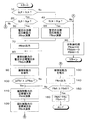
特に、制動制御装置44は、左右の前輪36FL、36FRに回生制動力が付与されている状況において、アンチスキッド制御による制動力の制御が開始される可能性があるときには、それに備えて前輪の回生制動力を摩擦制動力にすり替えるための制御を行う。この制動力のすり替え制御は、図2に示されたフローチャートに従って行われる。
In particular, the
後に詳細に説明する如く、前輪の制動スリップ量SLfl及びSLfrの何れかが基準値SLp(正の定数)を越えると、制動制御装置44は、その時点を基準時点として、基準時点における制動スリップ量等に基づいて暫定の目標回生制動力Ffbrptを演算する。この場合、暫定の目標回生制動力Ffbrptは、前輪の制動スリップ量が増大することを抑制するための前輪の暫定の目標制動力Ffbptに対応する目標回生制動力であり、基準時点における目標回生制動力Ffbrt0よりも所定値低い値である。この場合、所定値は、基準時点における前輪の目標制動力Ffbt0と前輪の暫定の目標制動力Ffbptとの差である。
As will be described in detail later, when any one of the braking slip amounts SLfl and SLfr of the front wheels exceeds a reference value SLp (a positive constant), the
そして、制動制御装置44は、回生制動力を暫定の目標回生制動力Ffbrptに低減して保持し、前輪の摩擦制動力を漸増させる。さらに、制動制御装置44は、制動力のすり替え開始後の摩擦制動力の増大量が所定値ΔFfbrp(=Ffbrt0−Ffbrpt)以上になると、好ましくは所定値ΔFfbrpと一致すると、回生制動力を0になるまで漸減し、摩擦制動力を目標制動力になるまで漸増させる。この場合、回生制動力の漸減及び摩擦制動力の漸増は、回生制動力と摩擦制動力との和が基準時点における前輪の目標制動力になるよう、行われる。
Then, the
また、前輪の回生制動力が0になった後に、前輪の制動スリップ量SLfl及びSLfrの何れかが基準値SLs(SLpよりも大きい正の定数)を越えると、制動制御装置44は、アンチスキッド制御による当該車輪の摩擦制動力の個別制御を開始する。そして、制動制御装置44は、当該車輪の制動スリップ量SLfl又はSLfが終了基準値SLe(SLsよりも小さい正の定数)以下になると、アンチスキッド制御による摩擦制動力の制御を終了する。
If any of the braking slip amounts SLfl and SLfr of the front wheels exceeds the reference value SLs (a positive constant larger than SLp) after the regenerative braking force of the front wheels becomes zero, the
また、前輪の回生制動力が0になる前に、前輪の制動スリップ量SLfl及びSLfrの何れかが基準値SLsを越えると、制動制御装置44は、前輪の回生制動力が0になるようエンジン制御装置38に対し0の目標回生制動力Ffbrtを示す信号を出力する。また、制動制御装置44は、回生制動力の低下量に対応する増大量にて前輪の摩擦制動力を増大させる。そして、制動制御装置44は、アンチスキッド制御による当該車輪の摩擦制動力の個別制御を開始する。
If any of the braking slip amounts SLfl and SLfr of the front wheels exceeds the reference value SLs before the regenerative braking force of the front wheels becomes zero, the
なお、前輪の回生制動力が0になった後に、予め設定された基準時間が経過してもアンチスキッド制御の開始条件が成立しない等の予め設定された復帰条件が成立すると、上記制動力のすり替えとは逆のすり替えが行われる。すなわち、回生制動力が増大され、摩擦制動力が低減されることにより、前輪の制動力の制御は通常の制御に復帰し、回生制動力Ffbrは目標回生制動力Ffbrtになるよう制御され、前輪の摩擦制動力Ffbは目標摩擦制動力Ffbftになるよう制御される。 If a predetermined return condition such as the anti-skid control start condition is not satisfied even after a preset reference time has elapsed after the regenerative braking force of the front wheels becomes zero, the braking force is The reverse of the replacement is performed. That is, when the regenerative braking force is increased and the frictional braking force is reduced, the control of the braking force of the front wheels returns to the normal control, and the regenerative braking force Ffbr is controlled to become the target regenerative braking force Ffbrt. The friction braking force Ffb is controlled to be the target friction braking force Ffbft.
また、回生制動力は左右の後輪36RL、36RRに付与されないので、後輪の制動スリップ量SLrl及びSLrrの何れかが基準値SLsを越えると、制動制御装置44は、当該車輪についてアンチスキッド制御による摩擦制動力の個別制御を開始する。そして、制動制御装置44は、当該車輪の制動スリップ量SLrl又はSLrrが終了基準値SLe以下になると、アンチスキッド制御による摩擦制動力の制御を終了する。
In addition, since the regenerative braking force is not applied to the left and right rear wheels 36RL and 36RR, if any one of the rear wheel braking slip amounts SLrl and SLrr exceeds the reference value SLs, the
次に、図2に示されたフローチャートを参照して実施形態においてアンチスキッド制御による制動力の制御に備えて行われる制動力のすり替え制御ルーチンについて説明する。なお、図2に示されたフローチャートによる制動力のすり替え制御は、左右の前輪36FL、36FRに回生制動力が付与されている状況において、所定の時間毎に繰返し実行される。また、以下の説明においては、図2に示されたフローチャートによる制動力のすり替え制御を必要に応じて単に「制御」と呼ぶこととする。 Next, a braking force replacement control routine performed in preparation for the braking force control by the anti-skid control in the embodiment will be described with reference to the flowchart shown in FIG. Note that the braking force replacement control according to the flowchart shown in FIG. 2 is repeatedly executed at predetermined intervals in a situation where regenerative braking force is applied to the left and right front wheels 36FL, 36FR. In the following description, the braking force replacement control according to the flowchart shown in FIG. 2 is simply referred to as “control” as necessary.
まず、ステップ10においては、図には示されていないアンチスキッド制御ルーチンに従って演算された左右の前輪36FL及び36FRの制動スリップ量SLfl及びSLfrについて、SLflがSLfrよりも大きいか否かの判別が行われる。そして、否定判別が行われたときには制御はステップ40へ進み、肯定判別が行われたときには制御はステップ20へ進む。
First, in
ステップ20においては、左前輪36FLの制動スリップ量SLflが基準値SLpを越えているか否かの判別、すなわちアンチスキッド制御による左前輪の制動力の制御に備えて前輪の回生制動力を摩擦制動力にすり替えるべきであるか否かの判別が行われる。そして、否定判別が行われたときには制御はステップ60へ進み、肯定判別が行われたときには制御はステップ30へ進む。
In
ステップ30においては、左前輪の制動スリップ量SLflが増大することを抑制するための前輪の暫定の目標制動力Ffbfptに対応する暫定の目標回生制動力Ffbrptが、下記の式(1)に従って演算される。なお、下記の式(1)の関数fxの変数は以下の通りであり、Izfは前輪の慣性モーメント(既知の一定値)である。また、左前輪の接地荷重Fflz及び路面の推定摩擦係数μは、当技術分野において公知の要領にて推定された値であってよい。
Ffbrpt=fx(SLfl,SLfld,Ffbr,Fflbf,Izf,Fflz,μ) …(1)
SLfld=左前輪の制動スリップ量SLflの変化率(例えば時間微分値)
Ffbr=現在の回生制動力
Fflbf=左前輪の摩擦制動力
Fflz=左前輪の接地荷重
μ=路面の推定摩擦係数
In
Ffbrpt = fx (SLfl, SLfld, Ffbr, Fflbf, Izf, Fflz, μ) (1)
SLfld = change rate of braking slip amount SLfl of the left front wheel (for example, time differential value)
Ffbr = Current regenerative braking force Fflbf = Left front wheel friction braking force Fflz = Left front wheel ground load μ = Estimated friction coefficient of road surface
ステップ40においては、右前輪36FRの制動スリップ量SLfrが基準値SLpを越えているか否かの判別、すなわちアンチスキッド制御による右前輪の制動力の制御に備えて前輪の回生制動力を摩擦制動力にすり替えるべきであるか否かの判別が行われる。そして、否定判別が行われたときには制御はステップ60へ進み、肯定判別が行われたときには制御はステップ50へ進む。
In
ステップ50においては、右前輪の制動スリップ量SLfrが増大することを抑制するための前輪の暫定の目標制動力Ffbfptに対応する暫定の目標回生制動力Ffbrptが、下記の式(2)に従って演算される。なお、下記の式(2)の関数fyの変数は以下の通りである。また、右前輪の接地荷重Ffrzは当技術分野において公知の要領にて推定された値であってよく、Izf及びμは上記式(1)の場合と同一である。
Ffbrpt=fy(SLfr,SLfrd,Ffbr,Ffrbf,Izf,Ffrz,μ) …(2)
SLfrd=右前輪の制動スリップ量SLfrの変化率(例えば時間微分値)
Ffbr=現在の回生制動力
Ffrbf=右前輪の摩擦制動力
Ffrz=右前輪の接地荷重
μ=路面の推定摩擦係数
In
Ffbrpt = fy (SLfr, SLfrd, Ffbr, Ffrbf, Izf, Ffrz, μ) (2)
SLfrd = change rate of braking slip amount SLfr of the right front wheel (for example, time differential value)
Ffbr = Current regenerative braking force Ffrbf = Right front wheel friction braking force Ffrz = Right front wheel ground load μ = Estimated friction coefficient of road surface
ステップ60においては、非制御処理、すなわち、制動力のすり替えが実行されないようにする処理が行われる。具体的には、暫定の目標回生制動力Ffbrpt、後述の摩擦制動力の暫定の目標増大勾配Ffbfpdt及び摩擦制動力の目標増大勾配Ffbfdtが、それぞれ0にリセットされ、しかる後制御はステップ10へ戻る。
In
ステップ70においては、暫定の目標回生制動力Ffbrptを示す信号がエンジン制御装置38へ出力され、これにより回生制動力Ffbrが暫定の目標回生制動力Ffbrptになるよう、回生制動装置14が制御される。
In
ステップ80においては、基準時点より予め設定された時間Ts(1秒程度の正の定数)が経過する時点において制動力のすり替えを完了させるための前輪の摩擦制動力の暫定の目標増大率Ffbfpdtが、下記の式(3)に従って演算される。なお、「基準時点」は、制動スリップ量SLfl又はSLfrが基準値SLpを越えた時点、すなわちステップ20又は40において最初に肯定判別が行われた時点である。また、下記の式(3)において、Ffbrt0は基準時点における前輪の目標制動力Ffbtであり、Ffbf0は基準時点における前輪の摩擦制動力であり、Tspは基準時点からの経過時間である。
Ffbfpdt=(Ffbt0−Ffbf0)/(Ts−Tsp) …(3)
In
Ffbfpdt = (Ffbt0−Ffbf0) / (Ts−Tsp) (3)
ステップ90においては、前輪の摩擦制動力Ffbfが暫定の目標増大率Ffbfpdtにて増大するよう、摩擦制動装置12が制御される。例えば、前輪の暫定の目標摩擦制動力Ffbfptが下記の式(4)に従って演算され、前輪の摩擦制動力Ffbfが暫定の目標摩擦制動力Ffbfptになるよう、摩擦制動装置12が制御される。なお、下記の式(4)及び後述の式(7)、(8)において、Ffbffは前輪の摩擦制動力の前回値であり、ΔTは図2に示されたフローチャートのサイクルタイムである。
Ffbfpt=Ffbff+Ffbfpdt*ΔT …(4)
In
Ffbfpt = Ffbff + Ffbfpdt * ΔT (4)
ステップ100においては、基準時点における目標回生制動力Ffbrt0と暫定の目標回生制動力Ffbrptとの差Ffbrt0−Ffbrptが、回生制動力Ffbrの暫定低減量、すなわち所定値ΔFfbrpとして演算される。また、前輪の現在の摩擦制動力Ffbfと基準時点における前輪の摩擦制動力Ffbf0との差Ffbf−Ffbf0が、基準時点以降の前輪の摩擦制動力Ffbfの総増大量ΔFfbfとして演算される。そして、摩擦制動力の総増大量ΔFfbfが所定値ΔFfbrp以上になったか否かの判別が行われ、否定判別が行われたときには制御はステップ80へ戻り、肯定判別が行われたときには制御はステップ110へ進む。
In
ステップ110においては、基準時点より予め設定された時間Tsが経過する時点において制動力のすり替えを完了させるための前輪の摩擦制動力の目標増大率Ffbfdtが、上記式(3)と同様の下記の式(5)に従って演算される。
Ffbfdt=(Ffbt0−Ffbf0)/(Ts−Tsp) …(5)
In
Ffbfdt = (Ffbt0−Ffbf0) / (Ts−Tsp) (5)
ステップ120においては、基準時点より予め設定された時間Tsが経過する時点において制動力のすり替えを完了させるための前輪の回生制動力の目標減少率Ffbrdtが、下記の式(6)に従って演算される。
Ffbrdt=−(Ffbrt0−ΔFfbrp)/(Ts−Tsp) …(6)
In
Ffbrdt = − (Ffbrt0−ΔFfbrp) / (Ts−Tsp) (6)
ステップ130においては、前輪の摩擦制動力Ffbfが目標増大率Ffbfdtにて増大するよう、摩擦制動装置12が制御される。例えば、前輪の目標摩擦制動力Ffbftが下記の式(7)に従って演算され、前輪の摩擦制動力Ffbfが目標摩擦制動力Ffbftになるよう、摩擦制動装置12が制御される。
Ffbft=Ffbff+Ffbfdt*ΔT …(7)
In
Ffbft = Ffbff + Ffbfdt * ΔT (7)
ステップ140においては、前輪の目標回生制動力Ffbrtが下記の式(8)に従って演算される。そして、目標回生制動力Ffbrtを示す信号がエンジン制御装置38へ出力され、これにより回生制動力Ffbrが目標回生制動力Ffbrtになるよう、回生制動装置14が制御される。なお、下記の式(8)において、Ffbrfは前輪の回生制動力の前回値である。
Ffbrt=Ffbrf+Ffbrdt*ΔT …(8)
In
Ffbrt = Ffbrf + Ffbrdt * ΔT (8)
ステップ150においては、ステップ130において演算された前輪の目標摩擦制動力Ffbftが基準時点における前輪の目標制動力Ffbt0以上であるか否かの判別、すなわち制動力のすり替えが完了したか否かの判別が行われる。そして、否定判別が行われたときには制御はステップ110へ戻り、肯定判別が行われたときには制御はステップ160へ進む。
In
ステップ160においては、前輪の目標摩擦制動力Ffbftが前輪の目標制動力Ffbtに設定されると共に、目標回生制動力Ffbrtが0に設定され、図2に示されたフローチャートによる制動力のすり替え制御が終了する。なお、これ以降においては、前輪に回生制動力が付与されることなく、前輪の目標摩擦制動力Ffbftが前輪の目標制動力Ffbtに設定され、左右前輪の目標摩擦制動力Fflbft、Ffrbftがそれぞれ前輪の目標摩擦制動力Ffbftの2分の1に制御される。そして、必要に応じてアンチスキッド制御による摩擦制動力の制御が実行される。また、予め設定された復帰条件が成立すると、制動力の制御は左右前輪に回生制動力を付与する通常時の制動力の制御に復帰する。
In
以上の説明より解る如く、ステップ20又は40及びステップ70〜90により、回生制動力を摩擦制動力にすり替えるための予備制御が行われる。また、ステップ110〜160により、回生制動力を摩擦制動力にすり替えるための本制御が行われる。制動力のすり替えの本制御は、基準時点より所定の時間が経過した時点において開始されるので、「所定の時間」は制動力のすり替えの予備制御の継続時間と同一である。
As can be understood from the above description, preliminary control for replacing the regenerative braking force with the friction braking force is performed in
<前輪に回生制動力のみが付与されている場合>
次に、前輪に回生制動力のみが付与されている場合について、図2に示されたフローチャート及び図3に示されたタイムチャートを参照して実施形態の作動を説明する。また、前輪に回生制動力に加えて摩擦制動力が付与されている場合について、図2に示されたフローチャート及び図4に示されたタイムチャートを参照して実施形態の作動を説明する。
<When only the regenerative braking force is applied to the front wheels>
Next, the operation of the embodiment will be described with reference to the flowchart shown in FIG. 2 and the time chart shown in FIG. 3 when only the regenerative braking force is applied to the front wheels. The operation of the embodiment will be described with reference to the flowchart shown in FIG. 2 and the time chart shown in FIG. 4 in the case where the friction braking force is applied to the front wheels in addition to the regenerative braking force.
なお、図3及び図4において、実線は前輪の回生制動力Ffbrを示し、破線は前輪の摩擦制動力Ffbfを示している。また、一点鎖線は暫定目標摩擦制動力Ffbfptによる前輪の摩擦制動力Ffbfの変化を示し、二点鎖線は前輪の制動力Ffb、すなわち前輪の回生制動力Ffbrと摩擦制動力Ffbfとの和を示している。これらのことは、従来技術の場合について、図3と同様のタイムチャートを示す図5においても同様である。 3 and 4, the solid line indicates the regenerative braking force Ffbr of the front wheel, and the broken line indicates the friction braking force Ffbf of the front wheel. The alternate long and short dash line indicates the change in the front wheel friction braking force Ffbf due to the provisional target friction braking force Ffbfpt. ing. The same applies to FIG. 5 showing a time chart similar to FIG. 3 in the case of the prior art.
また、一般に、アンチスキッド制御による制動力の制御に備えて制動力のすり替えが行われるのは、運転者の制動操作量が増大され、前輪の目標制動力Ffbtが増大するときである。しかし、基準時点より制動力のすり替えが完了するまでの時間Tsは前述の如く1秒程度の短い時間である。よって、実施形態の作動の説明においては、前輪の目標制動力Ffbtは一定であると考えられてもよいので、図3乃至図5においては、前輪の目標制動力Ffbtは一定の値として示されている。 In general, the braking force is replaced in preparation for the control of the braking force by the anti-skid control when the amount of braking operation by the driver is increased and the target braking force Ffbt of the front wheels is increased. However, the time Ts from the reference time until the replacement of the braking force is completed is as short as about 1 second as described above. Therefore, in the description of the operation of the embodiment, the target braking force Ffbt of the front wheels may be considered to be constant. Therefore, in FIGS. 3 to 5, the target braking force Ffbt of the front wheels is shown as a constant value. ing.
まず、左右前輪の制動スリップ量SLfl及びSLfrのうちの大きい方の値が基準値SLpを越えると、ステップ20又は40において肯定判別が行われることにより、前輪の制動力のすり替えの予備制御が開始される。かくして制動力のすり替えの予備制御が開始される時点、すなわち基準時点は、図3に示されたタイムチャートの時点t1である。そして、ステップ30又は50において、前輪の制動スリップ量が増大することを抑制するための暫定の目標回生制動力Ffbrptが、前輪の制動スリップ量SLfl及びLfrのうちの大きい方の値等に基づいて演算される。また、ステップ70において、前輪の回生制動力Ffbrが暫定の目標回生制動力Ffbrptになるよう、回生制動装置14が制御される。
First, when the larger one of the braking slip amounts SLfl and SLfr of the left and right front wheels exceeds the reference value SLp, an affirmative determination is made in
基準時点t1以降においては、回生制動力Ffbrが暫定の目標回生制動力Ffbrptに制御されている状況にて、ステップ80及び90が繰り返し実行されることにより、前輪の摩擦制動力Ffbfが暫定の目標増大率Ffbfpdtにて増大するよう、摩擦制動装置12が制御される。暫定の目標増大率Ffbfpdtは基準時点より予め設定された時間Tsが経過する時点において制動力のすり替えを完了させるための前輪の摩擦制動力の目標増大率である。しかし、図3に示された一点鎖線及び破線の傾きの比較より解る如く、摩擦制動力が0より増大される場合の実際の増大率は、ホイールシリンダ内の圧力の上昇遅れ等に起因して暫定の目標増大率Ffbfpdtよりも小さくなる。
After the reference time t1, steps 80 and 90 are repeatedly executed in a situation where the regenerative braking force Ffbr is controlled to the provisional target regenerative braking force Ffbrpt, so that the front wheel friction braking force Ffbf becomes the provisional target. The
前輪の摩擦制動力Ffbfが増大し、基準時点t1以降の前輪の摩擦制動力Ffbfの総増大量ΔFfbf(Ffbf−Ffbf0)が所定値ΔFfbrp(=Ffbrt0−Ffbrpt)以上になると、ステップ100において肯定判別が行われる。この肯定判別が行われるのは時点t2であるとすると、時点t2以降において、制動力のすり替えの予備制御が終了する。そして、時点t2以降においてはステップ110及びステップ140〜160が繰り返し実行されることにより、制動力のすり替えの本制御、すなわち実質的な制動力のすり替えが行われる。
When the front wheel friction braking force Ffbf increases and the total increase amount ΔFfbf (Ffbf−Ffbf0) of the front wheel friction braking force Ffbf after the reference time point t1 exceeds a predetermined value ΔFfbrp (= Ffbrt0−Ffbrpt), an affirmative determination is made in
特に、ステップ110において、基準時点より予め設定された時間Tsが経過する時点t3において制動力のすり替えを完了させるための前輪の摩擦制動力の目標増大率Ffbfdtが演算される。また、ステップ120において、時点t3において制動力のすり替えを完了させるための前輪の回生制動力の目標減少率Ffbrdtが演算される。そして、ステップ130及び140において、前輪の摩擦制動力Ffbfが目標増大率Ffbfdtにて漸次増大されると共に、回生制動力Ffbrが減少率Ffbrdtにて漸次低下される。
In particular, at
前輪の摩擦制動力Ffbfが基準時点における前輪の目標制動力Ffbt0以上になると、ステップ150において肯定判別が行われる。この肯定判別が行われるのは時点t3であるとすると、時点t3においてはステップ160が実行されることにより、制動力のすり替えが完了する。よって、時点t3以降においては、前輪には摩擦制動力のみが付与される。
If the front wheel friction braking force Ffbf is equal to or greater than the front wheel target braking force Ffbt0 at the reference time, an affirmative determination is made in
かくして、実施形態によれば、図3において二点鎖線にて示されている如く、前輪の制動力Ffb(=Ffbr+Ffbf)は、制動力のすり替えの予備制御中には基準時点における前輪の目標制動力Ffbt0よりも低い値になる。しかし、前輪の制動力Ffbは、時点t2になるまで漸次増大し、時点t2以降において制動力のすり替えの本制御が行われる。よって、制動力の実質的なすり替えに先立って前輪の制動力を一時的に低下させて、前輪のスリップ量の増大を抑制することができるので、車両が旋回状態にあっても前輪の横力の不足に起因して車両がアンダーステア状態になる虞れを低減することができる。また、前輪の制動力Ffbが時点t2を越える長い時間にわたり目標制動力Ffbtよりも低い値になることを回避し、これにより車両の減速度が低下することに起因して車両の乗員が違和感を覚える虞れも低減することができる。 Thus, according to the embodiment, as indicated by a two-dot chain line in FIG. 3, the front wheel braking force Ffb (= Ffbr + Ffbf) is the target control of the front wheel at the reference time during the preliminary control of braking force replacement. The value is lower than the power Ffbt0. However, the braking force Ffb of the front wheels gradually increases until the time point t2, and the main control for replacing the braking force is performed after the time point t2. Therefore, it is possible to temporarily reduce the braking force of the front wheels prior to substantial replacement of the braking force, thereby suppressing an increase in the slip amount of the front wheels. Therefore, even if the vehicle is in a turning state, the lateral force of the front wheels It is possible to reduce the possibility that the vehicle is understeered due to the shortage of the vehicle. Further, it is avoided that the braking force Ffb of the front wheels becomes a value lower than the target braking force Ffbt for a long time exceeding the time point t2 , thereby causing the vehicle occupant to feel uncomfortable due to a decrease in the deceleration of the vehicle. The fear of remembering can also be reduced.
図5は、前輪に回生制動力のみが付与されている状況において、回生制動力による制動力の補填が行われない従来技術に従って制動力のすり替えが行われる場合の回生制動力及び摩擦制動力の変化を示すタイムチャートである。図示の従来技術においては、時点t1において制動力のすり替えの開始条件が成立したとすると、時点t1において回生制動力の低下及び摩擦制動力の増大が開始される。 FIG. 5 shows the regenerative braking force and the friction braking force when the braking force is replaced according to the conventional technique in which the braking force is not compensated by the regenerative braking force in a situation where only the regenerative braking force is applied to the front wheels. It is a time chart which shows a change. In the illustrated prior art, assuming that the start condition for replacing the braking force is satisfied at the time point t1, a decrease in the regenerative braking force and an increase in the frictional braking force are started at the time point t1.
しかし、図5において破線にて示されている如く、前輪の摩擦制動力Ffbfが0より増大される場合の増大率は、図5において一点鎖線にて示された本来の目標摩擦制動力Ffbftの増大率よりも小さくなる。時点t2において前輪の摩擦制動力Ffbfが本来の目標摩擦制動力Ffbftの増大率にて増大し得るようになるとすると、時点t2以降における前輪の摩擦制動力Ffbfは本来の目標摩擦制動力FfbftよりもΔFfbf(=Ffbft−Ffbf)低い値になる。 However, as indicated by a broken line in FIG. 5, the increase rate when the friction braking force Ffbf of the front wheels is increased from 0 is equal to the original target friction braking force Ffbft indicated by the one-dot chain line in FIG. It becomes smaller than the increase rate. If the front wheel friction braking force Ffbf can increase at the increase rate of the original target friction braking force Ffbft at time t2, the front wheel friction braking force Ffbf after time t2 is greater than the original target friction braking force Ffbft. ΔFfbf (= Ffbft−Ffbf) is a low value.
よって、前輪の摩擦制動力Ffbfは、時点t2から制動力のすり替えが完了すべき時点t3までの長い時間、目標制動力FfbtよりもΔFfbf低い値になる。そのため、車両全体の制動力が低下することに対処すべく運転者が制動操作量を増大させると、制動力の増大により早期にアンチスキッド制御の開始条件が成立し易くなると共に、車両の旋回時には前輪の横力の不足に起因して車両がアンダーステア状態になり易い。 Therefore, the friction braking force Ffbf of the front wheels is a value lower than the target braking force Ffbt by ΔFfbf for a long time from the time point t2 to the time point t3 at which the braking force replacement should be completed. Therefore, if the driver increases the amount of braking operation to cope with a decrease in the braking force of the entire vehicle, the anti-skid control start condition is easily established early due to the increase in the braking force. The vehicle is likely to be understeered due to insufficient lateral force of the front wheels .
これに対し、実施形態によれば、上述の如く前輪の制動力Ffbは時点t2以降においては基準時点t1における前輪の目標制動力Ffbt0と同一になるので、従来技術の場合に比して、運転者により制動操作量が増大される虞れを低減することができる。よって、運転者による制動力の増大に起因して早期にアンチスキッド制御の開始条件が成立する虞れや、前輪の横力が不足することに起因して車両がアンダーステア状態になる虞れを低減することができる。 On the other hand, according to the embodiment, as described above, the braking force Ffb of the front wheels becomes equal to the target braking force Ffbt0 of the front wheels at the reference time t1 after the time t2, so that the driving is performed as compared with the case of the prior art. The possibility that the amount of braking operation is increased by the person can be reduced. Therefore, it is possible to reduce the possibility that the anti-skid control start condition will be established early due to the increase of the braking force by the driver and that the vehicle will be understeered due to insufficient lateral force of the front wheels. can do.
また、制動力のすり替えが完了する前にアンチスキッド制御による制動力の制御の開始条件が成立すると、回生制動力を速やかに0にすると共に、摩擦制動力を速やかに前輪の目標制動力に増大させなければならない。しかるに、従来技術の場合には、図5に示されている如く、制動力のすり替えはそれが完了すべき時点t3よりも遅い時点t4にならないと完了しない。そのため、制動力のすり替えが完了する前にアンチスキッド制御による制動力の制御の開始条件が成立すると、回生制動力を0にするための回生制動力の低減量及び摩擦制動力を前輪の目標制動力に増大させるための増大量が大きくなる。そのため、アンチスキッド制御による制動力の制御が開始される直前における車両全体の制動力が不必要に変動すること及びこれに起因して車両の減速度が不自然に変動する虞れが高くなる。 In addition, if the start condition of the braking force control by the anti-skid control is satisfied before the braking force replacement is completed, the regenerative braking force is quickly reduced to 0 and the friction braking force is quickly increased to the target braking force of the front wheels. I have to let it. However, in the case of the prior art, as shown in FIG. 5, the replacement of the braking force is not completed unless the time t4 is later than the time t3 when it should be completed. Therefore, if the condition for starting the braking force control by the anti-skid control is satisfied before the replacement of the braking force is completed, the amount of reduction of the regenerative braking force and the friction braking force for reducing the regenerative braking force to zero are reduced. The amount of increase for increasing power increases. Therefore, there is a high possibility that the braking force of the entire vehicle immediately before the control of the braking force by the anti-skid control is unnecessarily changed and the deceleration of the vehicle is unnaturally changed due to this.
これに対し、実施形態によれば、上述の如く制動力のすり替えはすり替えが完了すべき時点t3において完了する。よって、制動力のすり替えが完了する前にアンチスキッド制御による制動力の制御の開始条件が成立しても、回生制動力を0にするための回生制動力の低減量及び摩擦制動力を前輪の目標制動力に増大させるための増大量は、従来技術の場合ほどには大きくならない。従って、アンチスキッド制御による制動力の制御が開始される直前における車両全体の制動力が不必要に変動すること及びこれに起因して車両の減速度が不自然に変動する虞れを低減することができる。 On the other hand, according to the embodiment, as described above, the replacement of the braking force is completed at the time t3 when the replacement should be completed. Therefore, even if the start condition of the braking force control by the anti-skid control is satisfied before the replacement of the braking force is completed, the reduction amount of the regenerative braking force and the friction braking force for reducing the regenerative braking force to zero are set to the front wheel. The amount of increase for increasing the target braking force is not as great as in the prior art. Therefore, it is possible to reduce the possibility that the braking force of the entire vehicle fluctuates unnecessarily immediately before the braking force control by the anti-skid control is started, and that the deceleration of the vehicle due to this fluctuates unnaturally. Can do.
図6は、実施形態及び上記特許文献1の制動力制御装置の場合について、車両が制動により減速されつつ直進走行状態より旋回走行状態へ移行する際の車両の走行挙動を示す説明図である。なお、図6において、110は車両102の走行に伴って直線領域から旋回領域へ変化する走行路を示し、一点鎖線112は走行路110に沿う車両102の好ましい走行軌跡を示している。
FIG. 6 is an explanatory diagram showing the traveling behavior of the vehicle when the vehicle is shifted from the straight traveling state to the turning traveling state while being decelerated by braking, in the case of the embodiment and the braking force control device of Patent Document 1 described above. In FIG. 6,
走行路110の直線領域の終点近傍の点P1において制動が開始され、車両102が減速しながら走行路110の旋回領域を走行し、点P2において左右前輪の制動スリップ量SLfl及びSLfrのうちの大きい方の値が基準値SLpを越えるものとする。
Braking is started at a point P1 in the vicinity of the end point of the straight line region of the traveling
上記特許文献1の制動力制御装置の場合には、点P2において左右前輪の制動スリップ量SLfl及びSLfrのうちの大きい方の値が基準値SLpを越えた後にも、前輪の制動力は目標制動力に制御され、低下されない。そのため、車両が走行路110の旋回領域を走行する状況において、前輪の横力が不足することに起因して車両がアンダーステア状態になり易い。
In the case of the braking force control device of Patent Document 1 described above, the braking force of the front wheels is not controlled even after the larger value of the braking slip amounts SLfl and SLfr of the left and right front wheels exceeds the reference value SLp at the point P2. Controlled by power and not reduced. Therefore, in a situation where the vehicle travels in the turning area of the
なお、回生制動力による制動力の補填が行われない従来技術の場合には、点P2において制動力のすり替えが開始され、車両全体の制動力が低下する。よって、運転者が車両の減速度の不足を感じ、制動操作量を過剰に増大させると、前輪の制動スリップ量が増大する。その結果、図6において二点鎖線114にて示されている如く、車両はアンダーステア挙動を示し、またアンチスキッド制御が早期に開始される。
In the case of the conventional technique in which the braking force is not compensated by the regenerative braking force, the braking force replacement is started at the point P2, and the braking force of the entire vehicle is reduced. Therefore, if the driver feels that the vehicle deceleration is insufficient and the braking operation amount is excessively increased, the braking slip amount of the front wheels increases. As a result, as indicated by a two-
これに対し、実施形態によれば、車両が点P2を通過した直後に前輪の制動力は前輪の制動スリップ量が増大することを抑制する値に低下され、しかる後前輪の目標制動力になるよう増大される。よって、前輪の制動スリップ量の増大が抑制されると共に、運転者により制動操作量が過剰に増大される虞れも低いので、車両がアンダーステア挙動を示したり、アンチスキッド制御が早期に開始されたりする虞れも低い。従って、図6において一点鎖線112にて示されている如く、車両は好ましい走行軌跡に沿って走行する。
On the other hand, according to the embodiment, immediately after the vehicle passes the point P2, the braking force of the front wheels is reduced to a value that suppresses an increase in the braking slip amount of the front wheels, and thus becomes the target braking force of the rear front wheels. Will be increased. Accordingly, an increase in the braking slip amount of the front wheels is suppressed, and the possibility that the braking operation amount is excessively increased by the driver is low, so that the vehicle exhibits an understeer behavior or antiskid control is started early. There is a low risk of doing this. Therefore, the vehicle travels along a preferable travel locus as indicated by a dashed
<前輪に回生制動力に加えて摩擦制動力が付与されている場合>
前輪に回生制動力に加えて摩擦制動力が付与されている場合にも、図2に示されたフローチャートの各ステップは、前輪に回生制動力しか付与されていない場合と同様に実行される。しかし、前輪に回生制動力に加えて摩擦制動力が付与されている場合には、ホイールシリンダ内の圧力は既に有効な制動力を発生できる程度に上昇している。よって、この状況において摩擦制動力が増大される場合の実際の増大率は、摩擦制動力が0より増大される場合の増大率よりも大きくなる。
<When friction braking force is applied to the front wheels in addition to regenerative braking force>
Even when a friction braking force is applied to the front wheels in addition to the regenerative braking force, each step of the flowchart shown in FIG. 2 is executed in the same manner as when only the regenerative braking force is applied to the front wheels. However, when a friction braking force is applied to the front wheels in addition to the regenerative braking force, the pressure in the wheel cylinder has already increased to such an extent that an effective braking force can be generated. Therefore, the actual increase rate when the friction braking force is increased in this situation is larger than the increase rate when the friction braking force is increased from zero.
そのため、制動力のすり替え開始後の前輪の摩擦制動力Ffbfの総増大量ΔFfbf(Ffbf−Ffbf0)は、前輪に回生制動力しか付与されていない場合に比して早く、所定値ΔFfbrp(=Ffbrt0−Ffbrpt)以上になる。その結果、ステップ100における判別が肯定判別になる時点t2′は、前輪に回生制動力しか付与されていない場合に於ける時点t2よりも基準時点t1に近い時点になる。そして、時点t2′以降においては、前輪の制動力Ffbは前輪の目標制動力Ffbt0と同一になる。
Therefore, the total increase amount ΔFfbf (Ffbf−Ffbf0) of the friction braking force Ffbf of the front wheels after the start of the braking force replacement is faster than the case where only the regenerative braking force is applied to the front wheels, and is a predetermined value ΔFfbrp (= Ffbrt0). -Ffbrpt) or more. As a result, the time point t2 ′ at which the determination in
よって、前輪に回生制動力しか付与されていない場合に比して、前輪の摩擦制動力Ffbfが目標制動力Ffbt0よりも低い値になる期間を短くすることができる。このことにより、前輪に回生制動力しか付与されていない場合に比して、制動力のすり替えの本制御を早期に開始することができ、また運転者の制動操作量が増大される虞れを低減することができる。 Therefore, compared with the case where only the regenerative braking force is applied to the front wheels, the period during which the friction braking force Ffbf of the front wheels is lower than the target braking force Ffbt0 can be shortened. As a result, compared with the case where only the regenerative braking force is applied to the front wheels, the main control for switching the braking force can be started earlier, and the driver's braking operation amount may be increased. Can be reduced.
また、時点t2′における前輪の暫定の目標摩擦制動力Ffbfptと実際の摩擦制動力Ffbfとの差は、前輪に回生制動力しか付与されていない場合に比して小さくなる。よって、時点t2′から時点t3までにおける実際の摩擦制動力Ffbfの増大率は、暫定の目標回生制動力Ffbrptの増大率に近い値になる。従って、前輪に回生制動力しか付与されていない場合に比して、実際の摩擦制動力の増大率及び前輪の回生制動力の減少率を小さくすることができる。 Further, the difference between the provisional target friction braking force Ffbfpt of the front wheels and the actual friction braking force Ffbf at the time point t2 ′ is smaller than when only the regenerative braking force is applied to the front wheels. Therefore, the actual increase rate of the friction braking force Ffbf from the time point t2 ′ to the time point t3 becomes a value close to the increase rate of the provisional target regenerative braking force Ffbrpt. Therefore, compared with the case where only the regenerative braking force is applied to the front wheels, the actual increase rate of the friction braking force and the decrease rate of the front wheel regenerative braking force can be reduced.
また、前輪に回生制動力に加えて摩擦制動力が付与されている場合にも、制動力のすり替えはそれが完了すべき時点t3において完了する。従って、回生制動力による制動力の補填が行われない従来技術の場合に比して、アンチスキッド制御による制動力の制御が時点t3よりも早く開始される状況において車両全体の制動力が不必要に変動すること及びこれに起因して車両の減速度が不自然に変動する虞れを低減することができる。 Further, even when a friction braking force is applied to the front wheels in addition to the regenerative braking force, the replacement of the braking force is completed at a time t3 when it should be completed. Therefore, the braking force of the entire vehicle is unnecessary in a situation where the braking force control by the anti-skid control is started earlier than the time point t3 as compared with the case of the prior art in which the braking force is not compensated by the regenerative braking force. And the possibility that the deceleration of the vehicle fluctuates unnaturally due to this fluctuation can be reduced.
なお、回生制動装置14の異常などにより前輪に回生制動力が付与されていない場合には、制動力のすり替えは不要であり、図2に示されたフローチャートによる制動力のすり替え制御は実行されない。
If the regenerative braking force is not applied to the front wheels due to an abnormality of the
特に、実施形態によれば、基準時点から時間Tsが経過する時点において制動力のすり替えが完了するよう、前輪の摩擦制動力の目標増大率Ffbfdt及び回生制動力の目標増大率Ffbrdtが演算される。よって、基準時点(時点t1)から摩擦制動力の総増大量ΔFfbfが所定値ΔFfbrp以上になったと判定される時点(時点t2)までの時間の長さに関係なく、基準時点から時間Tsが経過する時点において制動力のすり替えを完了させることができる。 In particular, according to the embodiment, the target increase rate Ffbfdt of the front wheel friction braking force and the target increase rate Ffbrdt of the regenerative braking force are calculated so that the replacement of the braking force is completed when the time Ts elapses from the reference time point. . Therefore, the time Ts elapses from the reference time point regardless of the length of time from the reference time point (time point t1) to the time point (time point t2) when the total increase amount ΔFfbf of the friction braking force is determined to be equal to or greater than the predetermined value ΔFfbrp. At this point, the replacement of the braking force can be completed.
以上においては、本発明を特定の実施形態について詳細に説明したが、本発明は上述の実施形態に限定されるものではなく、本発明の範囲内にて他の種々の実施形態が可能であることは当業者にとって明らかであろう。 Although the present invention has been described in detail with respect to specific embodiments, the present invention is not limited to the above-described embodiments, and various other embodiments are possible within the scope of the present invention. This will be apparent to those skilled in the art.
例えば、上述の実施形態においては、図2に示されたフローチャートによる制動力のすり替え制御は、前輪に回生制動力が付与されている状況において実行されるので、前輪に回生制動力及び摩擦制動力が付与されている状況においても実行される。しかし、図2に示されたフローチャートによる制動力のすり替え制御は、前輪に回生制動力のみが付与されている状況において実行されるよう修正されてもよい。 For example, in the above-described embodiment, the braking force replacement control according to the flowchart shown in FIG. 2 is executed in a situation where the regenerative braking force is applied to the front wheels. Therefore, the regenerative braking force and the friction braking force are applied to the front wheels. It is executed even in a situation where is assigned. However, the braking force replacement control according to the flowchart shown in FIG. 2 may be modified to be executed in a situation where only the regenerative braking force is applied to the front wheels.
その場合には、暫定の目標回生制動力Ffbrptは、前輪の制動スリップ量が増大することを抑制するための暫定の目標回生制動力として、それぞれ上記式(1)及び(2)に対応する下記の式(1′)又は(2′)に従って演算される。式(1′)及び(2′)は、それぞれ式(1)及び(2)との比較より解る如く、摩擦制動力Fflbf、Ffrbfを変数に含んでいない。
Ffbrpt=fx(SLfl,SLfld,Ffbr,Izf,Fflz,μ) …(1′)
Ffbrpt=fy(SLfr,SLfrd,Ffbr,Izf,Ffrz,μ) …(2′)
In that case, the provisional target regenerative braking force Ffbrpt is a provisional target regenerative braking force for suppressing an increase in the braking slip amount of the front wheels, and corresponds to the following equations (1) and (2), respectively. (1 ') or (2'). Equations (1 ′) and (2 ′) do not include the frictional braking forces Fflbf and Ffrbf as variables, as will be understood from comparison with equations (1) and (2), respectively.
Ffbrpt = fx (SLfl, SLfld, Ffbr, Izf, Fflz, μ) (1 ′)
Ffbrpt = fy (SLfr, SLfrd, Ffbr, Izf, Ffrz, μ) (2 ')
また、上述の実施形態においては、暫定の目標回生制動力Ffbrptは上記式(1)又は(2)に従って演算される。しかし、暫定の目標回生制動力Ffbrptは、前輪の制動スリップ量が増大することを抑制するための前輪の暫定の目標制動力Ffbptに対応する暫定の目標回生制動力として演算される限り、上記式(1)、(2)以外の式に従って演算されてもよい。例えば、暫定の目標回生制動力Ffbrptは、前輪の制動スリップ量が増大することを抑制するための前輪の暫定の目標制動力Ffbptが演算され、暫定の目標制動力Ffbptより前輪の摩擦制動力Ffbfを減算することにより演算されてもよい。 In the above-described embodiment, the provisional target regenerative braking force Ffbrpt is calculated according to the above formula (1) or (2). However, as long as the provisional target regenerative braking force Ffbrpt is calculated as a provisional target regenerative braking force corresponding to the provisional target braking force Ffbpt of the front wheels for suppressing an increase in the braking slip amount of the front wheels, the above formula It may be calculated according to an expression other than (1) and (2). For example, the provisional target regenerative braking force Ffbrpt is calculated as the provisional target braking force Ffbpt for the front wheels for suppressing an increase in the braking slip amount of the front wheels, and the friction braking force Ffbf for the front wheels is calculated from the provisional target braking force Ffbpt. May be calculated by subtracting.
また、上述の如く、前輪に回生制動力に加えて摩擦制動力が付与されている状況において摩擦制動力が増大される場合における予備制御中の摩擦制動力の増大率は、前輪に回生制動力しか付与されていない状況における摩擦制動力の増大率よりも大きい。よって、前輪に回生制動力しか付与されていない状況における暫定の目標回生制動力Ffbrptは、前輪に回生制動力に加えて摩擦制動力が付与されている状況において摩擦制動力が増大される場合における暫定の目標回生制動力よりも高い値に設定されてもよい。 Further, as described above, the increase rate of the friction braking force during the preliminary control when the friction braking force is increased in a situation where the friction braking force is applied to the front wheel in addition to the regenerative braking force is the regenerative braking force applied to the front wheel. It is larger than the increase rate of the frictional braking force in the situation where only this is applied. Therefore, the provisional target regenerative braking force Ffbrpt in the situation where only the regenerative braking force is applied to the front wheels is the case where the friction braking force is increased in the situation where the friction braking force is applied to the front wheels in addition to the regenerative braking force. A value higher than the provisional target regenerative braking force may be set.
また、暫定の目標回生制動力Ffbrptは、基準時点の回生制動力Ffbr0よりも所定値ΔFfbrp小さい回生制動力に設定され、所定値ΔFfbrpは基準時点の前輪のスリップ量等に応じて可変設定されるようになっている。しかし、所定値ΔFfbrpは予め設定された値であってもよい。その場合には、前輪に回生制動力に加えて摩擦制動力が付与されている状況における所定値ΔFfbrpは、前輪に回生制動力のみが付与されている状況における所定値よりも小さい値に設定されてよい。 The provisional target regenerative braking force Ffbrpt is set to a regenerative braking force that is smaller than the regenerative braking force Ffbr0 at the reference time by a predetermined value ΔFfbrp, and the predetermined value ΔFfbrp is variably set according to the slip amount of the front wheels at the reference time. It is like that. However, the predetermined value ΔFfbrp may be a preset value. In that case, the predetermined value ΔFfbrp in the situation where the friction braking force is applied to the front wheels in addition to the regenerative braking force is set to a value smaller than the predetermined value in the situation where only the regenerative braking force is applied to the front wheels. It's okay.
また、上述の実施形態においては、基準時点以降の前輪の摩擦制動力Ffbfの総増大量ΔFfbfが所定値ΔFfbrp以上になったと判定されたときに、基準時点より所定の時間が経過したと判定され、制動力すり替えの本制御が開始される。しかし、所定の時間(制動力すり替えの予備制御の継続時間)は、実験等に基づいて総増大量ΔFfbfが所定値ΔFfbrpになる時間として予め求められた一定の値に設定されてもよい。その場合には、前輪に回生制動力に加えて摩擦制動力が付与されている状況における所定の時間は、前輪に回生制動力しか付与されていない状況における所定の時間よりも短い時間に設定されてよい。 In the above-described embodiment, when it is determined that the total increase amount ΔFfbf of the friction braking force Ffbf of the front wheels after the reference time is equal to or greater than the predetermined value ΔFfbrp, it is determined that a predetermined time has elapsed from the reference time. Then, the main control of braking force replacement is started. However, the predetermined time (the duration of the preliminary control for replacing the braking force) may be set to a constant value obtained in advance as the time when the total increase amount ΔFfbf becomes the predetermined value ΔFfbrp based on experiments or the like. In that case, the predetermined time in the situation where the friction braking force is applied to the front wheels in addition to the regenerative braking force is set to be shorter than the predetermined time in the situation where only the regenerative braking force is applied to the front wheels. It's okay.
また、上述の実施形態においては、時間Tsは基準時点から制動力のすり替えが完了するまでの時間として予め設定されている。しかし、時間Tsはステップ100において肯定判別が行われた時点から制動力のすり替えが完了するまでの時間、すなわち本制御の継続時間として予め設定されてもよい。
Further, in the above-described embodiment, the time Ts is set in advance as the time from the reference time point until the replacement of the braking force is completed. However, the time Ts may be set in advance as the time from when the affirmative determination is made in
また、上述の実施形態においては、ステップ100において肯定判別が行われると、ステップ110において、基準時点から時間Tsが経過する時点において制動力のすり替えが完了するよう、前輪の摩擦制動力の目標増大率Ffbfdt及び回生制動力の目標増大率Ffbrdtが演算される。しかし、前輪の摩擦制動力の目標増大率Ffbfdt及び回生制動力の目標増大率Ffbrdtは予め設定された値であってもよく、基準時点の回生制動力Ffbrに応じて可変設定されてもよい。
In the above-described embodiment, when an affirmative determination is made in
また、前輪の摩擦制動力の目標増大率Ffbfdt及び回生制動力の目標増大率Ffbrdtは、基準時点より所定の時間が経過した時点(時点t2)の前輪の目標制動力及び回生制動力に基づいて演算されてもよい。さらに、前輪の摩擦制動力の目標増大率及び回生制動力の目標増大率は、基準時点より所定の時間が経過した時点以降の現在の前輪の目標制動力及び回生制動力に基づいて演算されることにより、逐次更新されてもよい。 The target increase rate Ffbfdt of the front wheel friction braking force and the target increase rate Ffbrdt of the regenerative braking force are based on the target braking force and regenerative braking force of the front wheel when a predetermined time has elapsed from the reference time (time point t2). It may be calculated. Further, the target increase rate of the friction braking force of the front wheels and the target increase rate of the regenerative braking force are calculated based on the current target braking force and regenerative braking force of the front wheels after a predetermined time has elapsed from the reference time point. Thus, it may be updated sequentially.
また、上述の実施形態においては、暫定の目標回生制動力Ffbrptはステップ100において肯定判別が行われるまで一定の値である。しかし、暫定の目標回生制動力Ffbrptは例えば前輪の目標制動力Ffbtに応じて可変設定されてもよい。
In the above-described embodiment, the provisional target regenerative braking force Ffbrpt is a constant value until an affirmative determination is made in
また、上述の実施形態においては、ハイブリッドシステム18の電動発電機22が回生制動装置14の回生発電機として機能するようになっている。しかし、回生制動装置14は前輪に回生制動力を付与することができる限り、任意の構成のものであってよい。
In the above-described embodiment, the
12…摩擦制動装置、14…回生制動装置、18…ハイブリッドシステム、20…ガソリンエンジン、22…電動発電機、38…エンジン制御装置、44…制動制御装置、50FR〜50RL…車輪速度センサ、52FR〜52RL,54…圧力センサ
DESCRIPTION OF
Claims (6)
前輪に回生制動力が付与されている状況にて少なくとも一方の前輪の制動スリップの度合が基準値を越えると、当該時点を基準時点として、前記基準時点以降で前記基準時点より所定の時間が経過する時点以前においては、前輪の制動力が目標制動力よりも低い値になるよう、前記基準時点における前輪の回生制動力よりも所定値低い暫定の目標回生制動力になるように前輪の回生制動力を制御しつつ、前輪の摩擦制動力が漸次増大するように前輪の摩擦制動力を制御し、
前記基準時点より所定の時間が経過した時点以降においては、前輪の制動力が目標制動力になるよう、前輪の回生制動力が漸次低下すると共に前輪の摩擦制動力が漸次増大するように、回生制動力を低下させる制御及び摩擦制動力を増大させる制御を行う
ことを特徴とする車両の制動力制御方法。 This is applied to a vehicle in which a regenerative braking force and a friction braking force are applied to a front wheel that is a steering wheel, calculates a target braking force of the front wheel, and controls a regenerative braking force and a friction braking force based on the target braking force. In the braking force control method,
If the degree of braking slip of at least one front wheel exceeds the reference value in a situation where regenerative braking force is applied to the front wheel, a predetermined time elapses from the reference time after the reference time, with that time as the reference time Before the starting time, the front wheel regenerative braking is performed so that the front wheel braking force is lower than the target braking force so that the provisional target regenerative braking force is lower than the front wheel regenerative braking force at the reference time by a predetermined value. While controlling the power, control the friction braking force of the front wheels so that the friction braking force of the front wheels gradually increases,
In later time when the predetermined time from the reference time has elapsed, so that the front wheel braking force becomes the target braking force, so that the front wheel of the friction braking force with the front wheel of the regenerative braking force is gradually decreased gradually increases, regeneration A vehicle braking force control method characterized by performing control for reducing braking force and control for increasing friction braking force.
Priority Applications (4)
| Application Number | Priority Date | Filing Date | Title |
|---|---|---|---|
| JP2013225717A JP6164045B2 (en) | 2013-10-30 | 2013-10-30 | Vehicle braking force control method |
| PCT/JP2014/079654 WO2015064771A1 (en) | 2013-10-30 | 2014-10-30 | Braking force control method for vehicle |
| CN201480059275.0A CN105683006B (en) | 2013-10-30 | 2014-10-30 | Braking force control method for vehicle |
| US15/028,493 US9895978B2 (en) | 2013-10-30 | 2014-10-30 | Braking force control method for vehicle |
Applications Claiming Priority (1)
| Application Number | Priority Date | Filing Date | Title |
|---|---|---|---|
| JP2013225717A JP6164045B2 (en) | 2013-10-30 | 2013-10-30 | Vehicle braking force control method |
Publications (2)
| Publication Number | Publication Date |
|---|---|
| JP2015085792A JP2015085792A (en) | 2015-05-07 |
| JP6164045B2 true JP6164045B2 (en) | 2017-07-19 |
Family
ID=52278696
Family Applications (1)
| Application Number | Title | Priority Date | Filing Date |
|---|---|---|---|
| JP2013225717A Expired - Fee Related JP6164045B2 (en) | 2013-10-30 | 2013-10-30 | Vehicle braking force control method |
Country Status (4)
| Country | Link |
|---|---|
| US (1) | US9895978B2 (en) |
| JP (1) | JP6164045B2 (en) |
| CN (1) | CN105683006B (en) |
| WO (1) | WO2015064771A1 (en) |
Families Citing this family (8)
| Publication number | Priority date | Publication date | Assignee | Title |
|---|---|---|---|---|
| JP5979101B2 (en) * | 2013-08-26 | 2016-08-24 | トヨタ自動車株式会社 | vehicle |
| JP6411980B2 (en) * | 2015-09-29 | 2018-10-24 | 株式会社アドヴィックス | Braking device for vehicle |
| JP6595417B2 (en) * | 2016-08-10 | 2019-10-23 | 株式会社アドヴィックス | Braking device for vehicle |
| JP6767819B2 (en) * | 2016-09-12 | 2020-10-14 | 株式会社Subaru | Vehicle braking force control device |
| KR102224145B1 (en) * | 2017-02-24 | 2021-03-05 | 현대자동차주식회사 | System and method for regenerative braking of vehicle |
| KR102603002B1 (en) * | 2018-11-16 | 2023-11-15 | 현대자동차주식회사 | Braking force control system for vehicle |
| JP7059980B2 (en) * | 2019-05-08 | 2022-04-26 | トヨタ自動車株式会社 | Vehicle braking control device |
| JP2021087235A (en) * | 2019-11-25 | 2021-06-03 | トヨタ自動車株式会社 | Braking apparatus for electric vehicle |
Family Cites Families (12)
| Publication number | Priority date | Publication date | Assignee | Title |
|---|---|---|---|---|
| JP4058932B2 (en) * | 2001-10-25 | 2008-03-12 | トヨタ自動車株式会社 | Brake control device for vehicle |
| JP2004142687A (en) | 2002-10-28 | 2004-05-20 | Hitachi Constr Mach Co Ltd | Slope-descending speed control device |
| EP1557331B1 (en) * | 2002-10-28 | 2011-02-23 | Hitachi Construction Machinery Co., Ltd | Downhill speed controller |
| JP2006311791A (en) * | 2005-03-31 | 2006-11-09 | Advics:Kk | Brake control unit for vehicles |
| JP4765487B2 (en) * | 2005-08-29 | 2011-09-07 | 株式会社アドヴィックス | Brake device for vehicle |
| JP5262777B2 (en) * | 2009-02-04 | 2013-08-14 | 日産自動車株式会社 | Brake control device for vehicle |
| JP5222329B2 (en) * | 2010-08-05 | 2013-06-26 | 本田技研工業株式会社 | Braking device for vehicle |
| JP2013035509A (en) | 2011-08-10 | 2013-02-21 | Toyota Motor Corp | Vehicle breaking force control device |
| DE102011111899A1 (en) * | 2011-08-30 | 2013-02-28 | Gm Global Technology Operations, Llc | Detection device and method for detecting a carrier of a transceiver, motor vehicle |
| JP5532032B2 (en) * | 2011-09-07 | 2014-06-25 | トヨタ自動車株式会社 | Brake control device for vehicle |
| JP6024333B2 (en) * | 2012-09-21 | 2016-11-16 | 日産自動車株式会社 | Brake control device for vehicle |
| JP5978943B2 (en) * | 2012-11-20 | 2016-08-24 | 日産自動車株式会社 | Braking control device |
-
2013
- 2013-10-30 JP JP2013225717A patent/JP6164045B2/en not_active Expired - Fee Related
-
2014
- 2014-10-30 WO PCT/JP2014/079654 patent/WO2015064771A1/en active Application Filing
- 2014-10-30 CN CN201480059275.0A patent/CN105683006B/en active Active
- 2014-10-30 US US15/028,493 patent/US9895978B2/en active Active
Also Published As
| Publication number | Publication date |
|---|---|
| CN105683006B (en) | 2018-09-11 |
| CN105683006A (en) | 2016-06-15 |
| WO2015064771A1 (en) | 2015-05-07 |
| JP2015085792A (en) | 2015-05-07 |
| US9895978B2 (en) | 2018-02-20 |
| US20160264002A1 (en) | 2016-09-15 |
Similar Documents
| Publication | Publication Date | Title |
|---|---|---|
| JP6164045B2 (en) | Vehicle braking force control method | |
| JP6261154B2 (en) | Vehicle control method using in-wheel motor | |
| US8504273B2 (en) | Coefficient of friction based limitation of the torque of a vehicle control loop | |
| JP5999047B2 (en) | Vehicle control device | |
| JP2013035509A (en) | Vehicle breaking force control device | |
| JP6056340B2 (en) | Braking control device | |
| JP2008105589A (en) | Vehicular brake control unit, and vehicular brake control method | |
| KR101732832B1 (en) | Vehicle movement dynamics control method | |
| JP2017109664A (en) | Braking force control device | |
| JP6497359B2 (en) | Vehicle driving support device | |
| JP4983270B2 (en) | Brake device | |
| EP3529113B1 (en) | Lateral dynamic control for regenerative and friction brake blending | |
| JP5766240B2 (en) | Braking device for vehicle | |
| JP5120297B2 (en) | Electric vehicle regenerative braking control device | |
| JP4732003B2 (en) | Driving force control device for electric vehicle | |
| JP5853682B2 (en) | Brake control device for vehicle | |
| JP4224824B2 (en) | Braking / driving force control device | |
| JP5849708B2 (en) | Vehicle driving force control device | |
| JP6387949B2 (en) | Brake control device for vehicle | |
| JP6225563B2 (en) | Vehicle control device | |
| JP2016190607A (en) | Control apparatus of vehicle | |
| JP5966994B2 (en) | Brake control device for vehicle | |
| JP7103080B2 (en) | Vehicle control device | |
| JP7413769B2 (en) | Brake control device | |
| JP6387675B2 (en) | Vehicle traction control device |
Legal Events
| Date | Code | Title | Description |
|---|---|---|---|
| A621 | Written request for application examination |
Free format text: JAPANESE INTERMEDIATE CODE: A621 Effective date: 20160201 |
|
| A131 | Notification of reasons for refusal |
Free format text: JAPANESE INTERMEDIATE CODE: A131 Effective date: 20161101 |
|
| A521 | Request for written amendment filed |
Free format text: JAPANESE INTERMEDIATE CODE: A523 Effective date: 20161216 |
|
| TRDD | Decision of grant or rejection written | ||
| A01 | Written decision to grant a patent or to grant a registration (utility model) |
Free format text: JAPANESE INTERMEDIATE CODE: A01 Effective date: 20170523 |
|
| A61 | First payment of annual fees (during grant procedure) |
Free format text: JAPANESE INTERMEDIATE CODE: A61 Effective date: 20170605 |
|
| R151 | Written notification of patent or utility model registration |
Ref document number: 6164045 Country of ref document: JP Free format text: JAPANESE INTERMEDIATE CODE: R151 |
|
| LAPS | Cancellation because of no payment of annual fees |