JP6163029B2 - Image processing apparatus and method - Google Patents
Image processing apparatus and method Download PDFInfo
- Publication number
- JP6163029B2 JP6163029B2 JP2013133097A JP2013133097A JP6163029B2 JP 6163029 B2 JP6163029 B2 JP 6163029B2 JP 2013133097 A JP2013133097 A JP 2013133097A JP 2013133097 A JP2013133097 A JP 2013133097A JP 6163029 B2 JP6163029 B2 JP 6163029B2
- Authority
- JP
- Japan
- Prior art keywords
- area
- region
- irregular
- image
- falsified
- Prior art date
- Legal status (The legal status is an assumption and is not a legal conclusion. Google has not performed a legal analysis and makes no representation as to the accuracy of the status listed.)
- Active
Links
Images


Classifications
-
- G—PHYSICS
- G06—COMPUTING; CALCULATING OR COUNTING
- G06T—IMAGE DATA PROCESSING OR GENERATION, IN GENERAL
- G06T1/00—General purpose image data processing
- G06T1/0021—Image watermarking
- G06T1/0028—Adaptive watermarking, e.g. Human Visual System [HVS]-based watermarking
-
- G—PHYSICS
- G06—COMPUTING; CALCULATING OR COUNTING
- G06T—IMAGE DATA PROCESSING OR GENERATION, IN GENERAL
- G06T2201/00—General purpose image data processing
- G06T2201/005—Image watermarking
- G06T2201/0201—Image watermarking whereby only tamper or origin are detected and no embedding takes place
Landscapes
- Engineering & Computer Science (AREA)
- Physics & Mathematics (AREA)
- General Physics & Mathematics (AREA)
- Theoretical Computer Science (AREA)
- Image Processing (AREA)
- Computer Vision & Pattern Recognition (AREA)
Description
本発明は、撮影画像における改竄領域を検知する画像処理に関する。 The present invention relates to image processing for detecting a falsified area in a captured image.
コンパクトディジタルカメラや一眼レフディジタルカメラなどで撮影された画像の改竄を検知する技術が提案されている(例えば、非特許文献1)。この技術は、電子透かしなどの付加的な情報を撮影画像に埋め込むことなく、撮影画像に元来含まれるパターンの解析や領域ごとの特徴量を比較して改竄を検知する。電子透かしなどの付加的な情報を埋め込まないため、付加的な情報の埋め込みによる撮影画像の画質劣化や処理時間の増加を生じることなく改竄を検知可能な利点がある。 A technique for detecting falsification of an image taken with a compact digital camera or a single-lens reflex digital camera has been proposed (for example, Non-Patent Document 1). This technique detects tampering by analyzing a pattern originally included in a photographed image and comparing feature quantities for each region without embedding additional information such as a digital watermark in the photographed image. Since additional information such as a digital watermark is not embedded, there is an advantage that tampering can be detected without causing deterioration of the image quality of the captured image and an increase in processing time due to the additional information embedding.
非特許文献1の技術は、部分領域ごとの特徴量の比較によって、改竄対象の画像の部分領域を当該画像の他の領域にコピーする改竄(以下、同一画像内コピー)を高精度に検知する。
The technique of
非特許文献1の技術は、同一画像内コピーによる改竄領域をコピー元の画像領域(以下、コピー元領域)とコピー先の画像領域(以下、コピー先領域)のコピーペアで一括りに検知する。しかし、コピーペアの何れがコピー元領域か、コピー先領域かを判定することができない。言い替えれば、真の改竄領域であるコピー先領域を特定することができない。
The technique of Non-Patent
本発明は、同一画像内コピーによる改竄領域を特定することを目的とする。 An object of the present invention is to specify a falsified area by copying in the same image.
また、同一画像内コピーにおけるコピー元領域とコピー先領域を特定することを他の目的とする。 Another object is to specify a copy source area and a copy destination area in the same intra-image copy.
さらに、別画像コピーによる改竄領域を特定することを他の目的とする。 Furthermore, another object is to specify a falsification area by another image copy.
本発明は、前記の目的を達成する一手段として、以下の構成を備える。 The present invention has the following configuration as one means for achieving the above object.
本発明にかかる画像処理は、撮像データにおいて現像処理が不規則な領域を不規則領域として検知し、前記撮像データにおいて特徴量が近似する少なくとも二つの領域を近似領域として検知し、前記不規則領域と前記近似領域に基づき、前記近似領域から前記撮像データの改竄領域を特定する。 In the image processing according to the present invention, an irregular region in the imaging data that is irregularly developed is detected as an irregular region, and at least two regions that approximate feature amounts in the imaging data are detected as approximate regions, and the irregular region is detected. Based on the approximate area, a falsified area of the imaging data is specified from the approximate area.
また、撮像データにおいて現像処理が不規則な領域を不規則領域として検知し、所定のサイズの画像領域ごとに、前記不規則領域の特徴量に近似する領域を前記撮像データから探索し、前記不規則領域の特徴量に近似する領域が検知された場合、当該不規則領域を前記撮像データの改竄領域として特定し、当該検知された領域を前記改竄領域のコピー元領域として特定する。 In addition, an irregular region that is irregularly developed in the imaging data is detected as an irregular region, and for each image region of a predetermined size, an area that approximates the feature amount of the irregular region is searched from the imaging data, and the irregularity is detected. When a region that approximates the feature amount of the regular region is detected, the irregular region is specified as a falsified region of the imaging data, and the detected region is specified as a copy source region of the falsified region.
さらに、前記不規則領域のうち、前記改竄領域として特定されなかった不規則領域を別画像コピーによる改竄領域として特定する。 Further, an irregular area that is not specified as the falsified area among the irregular areas is specified as a falsified area by another image copy.
本発明によれば、同一画像内コピーによる改竄領域を特定することができる。 According to the present invention, it is possible to specify a falsified area by copying within the same image.
また、同一画像内コピーにおけるコピー元領域とコピー先領域を特定することができる。 It is also possible to specify the copy source area and the copy destination area in the same image copy.
さらに、別画像コピーによる改竄領域を特定することができる。 Further, it is possible to specify a falsification area by another image copy.
以下、本発明にかかる実施例の画像処理を図面を参照して詳細に説明する。 Hereinafter, image processing according to an embodiment of the present invention will be described in detail with reference to the drawings.
[装置の構成]
図1のブロック図により実施例の画像処理装置として機能する情報処理装置100の構成例を示す。
[Device configuration]
The block diagram of FIG. 1 shows a configuration example of an
マイクロプロセッサ(CPU)101は、メモリ103をワークメモリとして、メモリ103やハードディスクドライブ(HDD)107などの記録媒体に記憶されたプログラムを実行し、画像処理装置100の動作全般または一部を制御する。なお、メモリ103にはRAMやROMなどが含まれる。ビデオコントローラ(VC)102は、CPU101の指示に従い、画像や文字などから構成される画面をモニタ110に表示するための制御を行う。
The microprocessor (CPU) 101 uses the
メモリコントローラハブ(MCH)104は、リンク111〜114を介して、CPU101、ビデオコントローラ(VC)102、メモリ103および入出力コントローラハブ(ICH)105の間のデータ転送を制御する所謂「ノースブリッジ」である。ICH105は、リンク115〜117を介して、ネットワークインタフェイスカード(NIC)106、HDD107、および、外部接続ポート108の間のデータ転送を制御する所謂「サウスブリッジ」である。なお、リンク111〜117は、例えばPCIやPCI Express(登録商標)などのパラレルバスまたはシリアルバス、SATAやUSBなどのシリアルバスである。
The memory controller hub (MCH) 104 is a so-called “north bridge” that controls data transfer between the
NIC106は、有線や無線のネットワーク120に接続するための通信インタフェイスである。HDD107は、CPU101が実行するOS、各種プログラム、各種データなどを格納する。外部接続ポート108は、外部機器を画像処理装置100に接続するための例えばUSB、IEEE1394などのシリアルバスのポートである。外部接続ポート108に入力装置109を接続することで、画像処理装置100は、入力装置109からデータを取得することができる。なお、入力装置109は、外部接続ポート108を介して、画像処理装置100にデータを入力する機器である。入力装置109としては、例えばキーボード、マウスなどのポインティングデバイス、ディジタルカメラなどの撮像装置や画像入力装置、メモリカードリーダライタなどのデータ入出力装置が挙げられる。また、外部接続ポート108としてHDMI(登録商標)ポートやDisplayPortを用意すれば、モニタ110を外部接続ポート108に接続することができる。
The NIC 106 is a communication interface for connecting to a wired or
実施例の画像処理装置は、後述する処理を実行するプログラムを、パーソナルコンピュータなどのコンピュータ機器である情報処理装置100に供給することで実現される。
The image processing apparatus according to the embodiment is realized by supplying a program for executing processing to be described later to the
[機能構成]
図2のブロック図により実施例の画像処理装置の機能構成例を説明する。この機能構成は、CPU101が後述する機能を実現するプログラムを実行することで実現される。
[Function configuration]
A functional configuration example of the image processing apparatus according to the embodiment will be described with reference to the block diagram of FIG. This functional configuration is realized by the
画像入力部201は、外部接続ポート108を介して入力装置109から画像データを入力し、入力画像データをメモリ103やHDD107などの所定領域に格納する。入力画像データは、ディジタルカメラが撮影した画像を表す画像データ(撮像データ)であり、そのデータフォーマットは例えばJPEG、TIFF、RAWである。
The
第一の検知部である不規則領域検知部202は、第一の単位画像領域ごとに、入力画像データから現像処理が不規則に施された領域(以下、不規則領域)を検知する。例えば、撮影に使用されたディジタルカメラのイメージセンサがもつカラーフィルタアレイ(CFA)パターンを入力画像データから推定し解析して、CFAパターンが不規則な領域を不規則領域として検知する。
The irregular
第二の検知部である近似領域検知部203は、第二の単位画像領域ごとに、入力画像データが表す画像の特徴量を抽出し、特徴量が一致または近似する少なくとも二つの単位画像領域を検知する。つまり、特徴量が一致または近似する少なくとも二つの単位画像領域が、入力画像データに含まれる同一画像内コピーされた領域ペア(以下、コピーペア領域)として検知される。
The approximate
改竄特定部204は、不規則領域検知部202が検知した不規則領域と近似領域検知部203が検知したコピーペア領域に基づき、真の改竄領域であるコピー先領域を特定する。
The
出力部205は、改竄特定部204が特定した改竄領域(コピー先領域)などを識別可能に可視表示するための情報を例えばモニタ110に出力する。例えば、改竄特定部204が特定した改竄領域を構成する第二の単位画像領域を示す矩形枠や当該領域のアウトラインなどを入力画像データが表す画像に重畳表示する。また、改竄領域や改竄の可能性がある領域が検知されなかった場合、非検知のメッセージをモニタ110に表示することもできる。
The
モード設定部206は、ユーザ指示として、改竄領域として特定(または表示)する領域の種類を指示する特定(または表示)モードを入力し、指示された特定(または表示)モードを改竄特定部204(または出力部205)に設定する。なお、特定(または表示)モードに応じた改竄特定部204(または出力部205)の動作の詳細は変形例1において説明する。
The
[不規則領域検知部]
●CFAパターン
CFAは、イメージセンサの例えばRGBカラーフィルタ配列であり、イメージセンサの各受光素子(画像における画素に対応する単位)のRGB受光パターンを示す。市場に流通する多くのイメージセンサは、コストダウンのために各受光素子がRGBの何れか一つの色情報を取得する構成を有し、効率的に色情報を取得するためにベイヤ配列などに代表されるCFAを用いて、入射光から色情報を取得する。
[Irregular area detector]
● CFA pattern
CFA is, for example, an RGB color filter array of the image sensor, and indicates an RGB light receiving pattern of each light receiving element (unit corresponding to a pixel in an image) of the image sensor. Many image sensors on the market have a configuration in which each light receiving element acquires any one of RGB color information for cost reduction, and is represented by a Bayer array to efficiently acquire color information. The CFA is used to obtain color information from the incident light.
CFAは、例えば2×2セルの正方形の配列を単位として、イメージセンサ上に規則的かつ周期的に配置される。図3によりCFAの一例を示す。図3(A)から図3(D)はベイヤ配列を示し、図3(E)はベイヤ配列の二つのグリーンGの一方にエメラルドグリーンEを配置したCFAである。CFAは、例えば図3(F)に示すように、イメージセンサ上に規則的かつ周期的に配置される。 The CFA is regularly and periodically arranged on the image sensor in units of, for example, a square array of 2 × 2 cells. An example of CFA is shown in FIG. 3A to 3D show a Bayer array, and FIG. 3E shows a CFA in which an emerald green E is arranged on one of two green Gs in the Bayer array. For example, as shown in FIG. 3F, the CFA is regularly and periodically arranged on the image sensor.
図4のフローチャートにより撮影時のディジタルカメラの処理を説明する。 The processing of the digital camera at the time of shooting will be described with reference to the flowchart of FIG.
撮像によって被写体の光学像は光電変換されディジタル信号に変換され(S1101)、ディジタル信号はRAW画像データとして取得される(S1102)。RAW画像データの色情報はイメージセンサのCFAパターンに依存し、図3(A)に示すCFAの場合、RAW画像データの各画素の色情報は図3(F)に示すようになる。 The optical image of the subject is photoelectrically converted into a digital signal by imaging (S1101), and the digital signal is acquired as RAW image data (S1102). The color information of the RAW image data depends on the CFA pattern of the image sensor. In the case of the CFA shown in FIG. 3 (A), the color information of each pixel of the RAW image data is as shown in FIG. 3 (F).
RAW画像データの各画素は、上述したように、一つの色情報しかもたないため、各画素にRGBの色情報をもたせる必要がある(フルカラー化)。そこで、各画素にRGBの色情報を与えるために、不足する色成分を周囲の画素から補間する(S1103)。例えば、図3(G)に示す注目画素1001はR成分だけをもつので、不足するB成分を周囲の四つのB画素から補間し、不足するG成分を周囲の四つのG画素から補間する。このような補間処理を含む現像処理を行うことで、RAW画像データからフルカラー画像データを取得する(S1104)。
Since each pixel of RAW image data has only one color information as described above, it is necessary to provide each pixel with RGB color information (full colorization). Therefore, in order to give RGB color information to each pixel, an insufficient color component is interpolated from surrounding pixels (S1103). For example, since the
このような色成分の補間処理は「デモザイキング」と呼ばれ、補間処理に用いた色補間アルゴリズムは「デモザイキングアルゴリズム(DMA)」と呼ばれる。DMAはカメラモデルやイメージセンサなどと一対一に対応し、DMAの種類にはバイリニア補間、ニアレストネイバ補間、AHD(adaptive homogeneity-directed)補間などがある。 Such interpolation processing of color components is called “Demosaicing”, and the color interpolation algorithm used for the interpolation processing is called “Demosaicing Algorithm (DMA)”. DMA has a one-to-one correspondence with camera models and image sensors, and types of DMA include bilinear interpolation, nearest neighbor interpolation, and AHD (adaptive homogeneity-directed) interpolation.
不規則領域検知部202は、不規則領域を検知するために、例えば、入力画像データから撮影に使用されたディジタルカメラのCFAパターンを推定し、CFAパターンが不規則な領域を特定する。なお、入力画像データがRAW画像データの場合、各画素がもつ色情報のパターンがそのままCFAパターンである。一方、入力画像データがフルカラー画像データの場合、各画素がすべての色成分をもつため、CFAパターンを推定する必要がある。
In order to detect an irregular region, the irregular
●CFAパターンの推定方法
CFAパターンの推定は、第一の単位画像領域(以下、推定領域)ごとに行う。推定領域はA×B画素の矩形領域であり、例えばA=B=64の64×64画素とすることができる。ただし、推定領域が小さいと、CFAパターンの誤推定が発生する虞があり、推定領域はできるだけ大きい方が望ましい。
● CFA pattern estimation method
The CFA pattern is estimated for each first unit image area (hereinafter, estimated area). The estimation area is a rectangular area of A × B pixels, and can be, for example, 64 × 64 pixels with A = B = 64. However, if the estimated area is small, there is a risk of erroneous estimation of the CFA pattern, and it is desirable that the estimated area is as large as possible.
不規則領域検知部202は、推定領域ごとに、フルカラー画像データのCFAパターンが図3(A)から図3(D)に示す四つのベイヤ配列の何れに相当するかを推定する。つまり、四つのベイヤ配列に従うバイリニア補間などの簡単な線形補間を推定領域のフルカラー画像に施す(以下、再デモザイキング)。そして、再デモザイキング後の、推定領域の、四つの画像データと元のフルカラー画像データの間のG成分の最小二乗誤差を計算し、最小二乗誤差が最小の画像データの再デモザイキングに用いたベイヤ配列を注目推定領域のCFAパターンと判定する。このような処理を入力画像データ全体に施すことで、入力画像データのCFAパターンを推定する。
The irregular
なお、上記のCFAパターンの推定方法は一例である。他の推定方法として、例えば、公知のメタデータであるExif(exchangeable image file format)情報を利用する方法がある。つまり、入力画像データのExif情報に含まれるCFAパターンを入力画像データの真のCFAパターンとして用いて、入力画像データを再デモザイキングし、再デモザイキング後の画像データと入力画像データの間の画素値を比較する。この比較により、真のCFAパターンと異なるCFAパターンをもつ領域を特定することができる。また、入力画像データの現像時の色補間に用いられたDMAが既知の場合は、当該DMAを用いて再デモザイキングすることで、CFAパターンが異なる領域をより高精度に検知することができる。 The above CFA pattern estimation method is an example. As another estimation method, for example, there is a method using Exif (exchangeable image file format) information which is publicly known metadata. In other words, using the CFA pattern included in the Exif information of the input image data as the true CFA pattern of the input image data, the input image data is re-demosaiced, and the pixels between the image data after the re-demosamicing and the input image data Compare values. By this comparison, an area having a CFA pattern different from the true CFA pattern can be specified. In addition, when the DMA used for color interpolation at the time of developing the input image data is known, it is possible to detect a region having a different CFA pattern with higher accuracy by performing demosaicing again using the DMA.
●不規則領域の検知
図5により不規則領域検知部202による不規則領域の検知処理を説明する。
Irregular Area Detection The irregular area detection process by the irregular
まず、別画像の部分領域を、改竄検知対象の画像にコピーする改竄(以下、別画像コピー)を、入力画像データから検知する例を説明する。 First, an example will be described in which falsification (hereinafter referred to as another image copy) for copying a partial area of another image to an image to be falsified is detected from input image data.
例えば、図5(A)に示す画像データのCFAパターンが図5(A)に示すベイヤ配列だと仮定する。このとき、図5(B)に示すように、図5(C)に示すCFAパターンをもつ別画像からの別画像コピーによる改竄が入力画像データに施されている場合、別画像コピー領域1201のCFAパターン1202だけが周囲と異なる。つまり、不規則領域検知部202は、周囲とCFAパターンが異なる領域1201を不規則領域として検知し、当該領域1201を改竄領域と判定する。
For example, assume that the CFA pattern of the image data shown in FIG. 5 (A) is the Bayer array shown in FIG. 5 (A). At this time, as shown in FIG. 5 (B), when the input image data is tampered with another image copy from another image having the CFA pattern shown in FIG. Only the
次に、同一画像内コピーによる改竄を検知する例を説明する。 Next, an example in which tampering due to copying within the same image is detected will be described.
例えば、図5(C)に示すように、部分領域1203を当該画像の別の領域1204に同一画像内コピーした改竄が入力画像データに施されている場合、領域1204のCFAパターン1206だけが周囲と異なる場合がある。つまり、同一画像内コピーにおいて、コピー元領域1203のCFAパターン1205とコピー先領域1204の本来のCFAパターンが異なると、コピー先領域1204のCFAパターン1206が、周囲のCFAパターンの周期性を崩す(乱す)。つまり、不規則領域検知部202は、CFAパターンの周期性が崩れた(乱れた)領域1204を不規則領域として検知し、当該領域1204を改竄領域と判定する。
For example, as shown in FIG. 5C, when the input image data is tampered with the
なお、不規則領域検知部202は、検知結果として、推定領域の左上の画素座標と推定領域のサイズをメモリ103などの所定領域に格納する。
Note that the irregular
図6により不規則領域の検知を説明する。図6(A)をオリジナルの画像データ、図6(B)を部分領域1301が同一画像内コピーされた領域1302を有する改竄画像データとする。図6(B)に示す改竄画像データが入力されたとすると、不規則領域検知部202は、図6(D)にハッチングで示す領域1304を不規則領域として検知する。
The detection of irregular regions will be described with reference to FIG. 6A is original image data, and FIG. 6B is falsified image data having a
なお、不規則領域検知部202は、検知した不規則領域が同一画像内コピーによるものか、別画像コピーによるものかを判別することはできない。さらに、近似領域検知部203よりも同一画像内コピーによる改竄の検知精度は低く、例えば、不規則領域検知部202による検知は、図6(D)に示す領域1304のように、改竄領域の概略位置が分かる程度である。
Note that the irregular
また、CFAパターンが異なる領域だけでなく、現像時のDMAが異なる領域や、デモザイキング時の色補間に用いた画素(参照画素)が異なる領域を不規則領域として検知することもできる。 In addition to regions having different CFA patterns, regions having different DMAs during development, and regions having different pixels (reference pixels) used for color interpolation during demosaicing can be detected as irregular regions.
[近似領域検知部]
図7により同一画像内コピーによるコピーペア領域の検知を説明する。
[Approximate area detector]
With reference to FIG. 7, the detection of a copy pair area by copying within the same image will be described.
近似領域検知部203は、図7に示す入力画像データの第二の単位画像領域(以下、特徴量抽出領域)に相当する注目ブロック901の特徴量と、特徴量抽出領域に相当する他のブロック(比較ブロック)902の特徴量を例えば主成分分析を利用して抽出する。そして、両者の特徴量を比較し、それらが一致する(または、それらの差分が所定の閾値以下の)場合、注目ブロック901と比較ブロック902を同一画像内コピーによるコピーペア領域と判定する。
The approximate
特徴量抽出領域はX×Y画素の矩形領域とする。例えばX=4、Y=4の場合、特徴量抽出領域は4×4画素になり、入力画像データが表す画像を512×512画素とすると、入力画像データ全体から合計128ブロック分の特徴量が抽出される。 The feature amount extraction area is a rectangular area of X × Y pixels. For example, when X = 4 and Y = 4, the feature amount extraction area is 4 × 4 pixels, and if the image represented by the input image data is 512 × 512 pixels, the feature amount for a total of 128 blocks is obtained from the entire input image data. Extracted.
特徴量の抽出に関して、特徴量抽出領域が互いに重畳しないように画像を分割してもよいが、特徴量抽出領域を例えば一画素ずつ横または縦に移動するように画像を分割してもよい。画像が512×512画素、特徴量抽出領域が4×4画素の場合、特徴量抽出領域を横に一画素ずつ計(512-4)回移動し、縦に一画素ずつ計(512-4)回移動すれば、画像全体で合計509×509ブロック分の特徴量を抽出することができる。 Regarding the feature amount extraction, the image may be divided so that the feature amount extraction regions do not overlap each other, but the image may be divided so that the feature amount extraction region is moved horizontally or vertically, for example, one pixel at a time. If the image is 512 x 512 pixels and the feature quantity extraction area is 4 x 4 pixels, the feature quantity extraction area is moved horizontally by one pixel (512-4) times, and vertically by one pixel (512-4) If the movement is performed once, it is possible to extract a total of 509 × 509 blocks of feature values for the entire image.
また、近似領域検知部203は、検知結果として、コピーペア領域の左上の画素座標と特徴量抽出領域のサイズをメモリ103などの所定領域に格納する。
Further, the approximate
なお、近似領域検知部203は、コピーペア領域の何れがコピー元のブロック(コピー元領域)か、コピー先のブロック(コピー先領域)かを判定することができない。例えば、不規則領域検知部202の説明と同様に、図6(A)をオリジナルの画像データ、図6(B)を部分領域1301が同一画像内コピーされた領域1302を有する改竄画像データとし、改竄画像データが入力されたとする。近似領域検知部203は、図6(C)にハッチングで示す領域1303をコピーペア領域として検知する。
The approximate
また、近似領域検知部203は、図6(F)に示す、部分領域1301の一部が同一画像内コピーされた領域1308も検知することができる。領域1308の検知結果は、図6(G)にハッチングで示す領域1309である。
Further, the approximate
また、近似領域検知部203は、上述するように、近似する特徴量をもつ領域ペアを検知するため、同一画像内コピーの後、コピー先領域が加工されたような改竄も検知することができる。例えば、部分領域を同一画像内コピーし、コピー先領域の境界領域を暈す処理が行われた改竄は、コピー元領域とコピー先領域の特徴量が近似するため検知可能である。
Further, as described above, the approximate
[改竄特定部]
図6を参照して、改竄特定部204の処理を説明する。なお、上述と同様、図6(A)がオリジナルの画像データ、図6(B)が同一画像内コピーにより改竄された入力画像データとする。そして、図6(B)の画像データから、近似領域検知部203により図6(C)に示すコピーペア領域1303が検知され、不規則領域検知部202により図6(D)に示す不規則領域1304が検知されたとする。
[Falsification Identification Department]
With reference to FIG. 6, the process of the
改竄特定部204は、コピーペア領域1303と不規則領域1304が重複する領域を、図6(E)に示すように、同一画像内コピーによる真の改竄領域1305として特定する。つまり、改竄特定部204は、不規則領域1304として検知された推定領域の座標とサイズ、および、コピーペア領域1303として検知された特徴量抽出領域の座標に基づき、コピーペア領域1303と不規則領域1304が重複するか否かを判定する。
The
例えば、画像の左上の画素を原点(X, Y)=(0, 0)とし、コピーペア領域1303に含まれる4×4画素の特徴量抽出領域の座標が(100, 100)、不規則領域の検知に64×64画素の推定領域が使用されたとする。この場合、検知された不規則領域1304に37≦X≦103かつ37≦Y≦103の推定領域が含まれれば、コピーペア領域1303と不規則領域1304が重複すると判定する。
For example, the upper left pixel of the image is the origin (X, Y) = (0, 0), the coordinates of the 4 × 4 pixel feature extraction area included in the
また、改竄特定部204は、特定した改竄領域(コピー先領域)1305に対してコピーペア領域を組む領域を、当該コピー先領域のコピー元領域として特定する。例えば、図6(E)においては、特定した改竄領域1305とコピーペア領域を組む領域1306がコピー元領域として特定される。さらに、改竄特定部204は、コピー先領域として特定されなかった不規則領域1304を別画像コピーによる改竄領域として特定する。
Further, the
また、入力画像データに、図6(F)に示すような部分領域1301の一部が同一画像内コピーされた領域1308が含まれる場合も、同様に、同一画像内コピーによる真の改竄領域(コピー先領域)を特定することができる。この場合、図6(F)の画像データから、近似領域検知部203により図6(G)に示すコピーペア領域1303、1309が検知され、不規則領域検知部202により図6(H)に示す不規則領域1304、1310が検知される。改竄特定部204は、図6(I)に示すように、コピーペア領域1303と不規則領域1304が重畳する領域1305、および、コピーペア領域1309と不規則領域1310が重畳する領域1311を改竄領域(コピー先領域)として特定する。さらに、コピーペア領域1303、1309と組をなす領域1306をコピー元領域として特定する。
Similarly, when the input image data includes an
また、同一画像内コピーの後、コピー先領域が加工されたような改竄であっても、近似領域検知部203が近似する特徴量をもつ領域ペアを検知し、上記と同様に、改竄特定部204は真の改竄領域(コピー先領域)を特定することができる。
In addition, even if the copy destination area has been modified after copying within the same image, the approximate
なお、改竄特定部204は、コピー先領域、コピー元領域、別画像コピーによる改竄領域それぞれについて、それら領域に含まれる特徴量抽出領域の左上の画素座標と特徴量抽出領域のサイズを改竄領域の特定結果としてメモリ103などの所定領域に格納する。
Note that the
[出力部]
図8により改竄検知結果の出力例を説明する。
[Output section]
An output example of the falsification detection result will be described with reference to FIG.
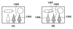
出力部205は、図8(A)に示すように、改竄特定部204が特定した改竄領域(コピー先領域)1305を例えばモニタ110に可視化表示する。
As shown in FIG. 8A, the
また、改竄領域が特定されなかった場合、検知された不規則領域とコピーペア領域を互いに識別可能に表示してもよい。例えば、コピーペア領域を赤色で表示し、不規則領域を青色で表示するなど、異なる色で表示してコピーペア領域と不規則領域を識別可能に表示する。 Further, when the falsified area is not specified, the detected irregular area and copy pair area may be displayed so as to be distinguishable from each other. For example, the copy pair area is displayed in red and the irregular area is displayed in blue. For example, the copy pair area and the irregular area are displayed in a distinguishable manner.
また、図8(B)に示すように、コピー先領域1305とコピー元領域1306を識別可能に表示することもできる。その際、コピー先領域1305のコピー元であるコピー元領域1306を明確化するために、両領域を結ぶ破線1307などを表示してもよい。
Further, as shown in FIG. 8B, the
また、別画像コピーによる改竄領域を同一画像内コピーによる改竄領域とは異なる色で表示して、別画像コピーによる改竄領域と同一画像内コピーによる改竄領域と識別可能に表示してもよい。 Further, the falsified area by another image copy may be displayed in a different color from the falsified area by the same image copy so that the falsified area by another image copy can be distinguished from the falsified area by the same image copy.
[改竄検知処理]
図9のフローチャートにより実施例の改竄検知処理を説明する。
[Falsification detection processing]
The falsification detection process of the embodiment will be described with reference to the flowchart of FIG.
画像入力部201は、入力装置109から撮影画像の画像データを入力する(S301)。不規則領域検知部202は、入力画像データから不規則領域を検知し(S302)、近似領域検知部203は、入力画像データから同一画像内コピーによるコピーペア領域を検知する(S303)。なお、ステップS302とS303は順不同である。例えば、ステップS303の後、ステップS302が実行されてもよいし、CPU101が二つ以上のCPUコアを有すマルチコアプロセッサであればステップS302とS303が並列処理されてもよい。
The
次に、改竄特定部204は、検知された不規則領域と検知されたコピーペア領域の重複領域を抽出し(S304)、重複領域を抽出したか否かを判定する(S305)。重複領域が抽出されなかった場合、処理はステップS308に進む。
Next, the
重複領域が抽出された場合、改竄特定部204は、前述した手順により改竄領域の特定を行う(S306)。つまり、真の改竄領域であるコピー先領域を特定し、例えばユーザの要求があればコピー元領域や別画像コピーによる改竄領域を特定する。そして、ステップS307の判定により、すべての重複領域について改竄領域の特定を行うまでステップS306の処理を繰り返す。
When the overlapping area is extracted, the
次に、出力部205は、改竄領域が特定されたか否かを判定し(S308)、改竄領域が特定された場合は改竄特定部204が特定した改竄領域を前述した方法で表示する(S309)。また、改竄領域が特定されなかった場合は不規則領域とコピーペア領域を前述した方法で表示する(S310)。なお、重複領域が抽出されなかった場合は改竄領域の特定も行われないから、出力部205はステップS310の処理を実行する。
Next, the
このように、CFAパターンの周期性の崩れ(乱れ)から検知される不規則領域、および、特徴量の一致または近似から検知される同一画像内コピーによるコピーペア領域の両方を用いて、コピー先領域とコピー元領域をそれぞれ検知することができる。つまり、真の改竄領域であるコピー先領域を高精度に検知することができる。 In this way, the copy destination is determined by using both the irregular area detected from the periodicity disorder (disturbance) of the CFA pattern and the copy pair area by copy in the same image detected from the coincidence or approximation of the feature amount. Each of the area and the copy source area can be detected. That is, the copy destination area that is a true falsification area can be detected with high accuracy.
[変形例1]
上記では、ステップS306の処理について「例えばユーザの要求があればコピー元領域や別画像コピーによる改竄領域を特定する」と説明したが、以下では、この点をより詳細に説明する。
[Modification 1]
In the above description, the processing in step S306 has been described as “for example, if there is a user request, a copy source region or a falsified region by another image copy is specified”, but this point will be described in more detail below.
図10のフローチャートにより変形例1における改竄検知処理を説明する。なお、図10において、図9に示す処理と略同等の処理には同一符号を付して、その詳細説明を省略する。
The falsification detection process in
モード設定部206は、特定モードを示すユーザ指示を入力する(S401)。特定モードには、コピー先領域のみを特定する「特定モード1」とコピー先領域とコピー元領域の両方を特定する「特定モード2」があり、ユーザは例えばモニタ110に表示されたユーザインタファイスを操作して特定モードを選択または指示する。例えば、ユーザは、改竄された領域だけを知りたい場合は特定モード1を指示し、改竄領域のコピー元も知りたい場合は特定モード2を指示する。
The
次に、ステップS301からS305の処理が実行され、重複領域が抽出された場合、改竄特定部204は特定モードを判定する(S402)。特定モード1が指定された場合、改竄特定部204は、コピー先領域を特定し(S403)、ステップS404の判定により、すべての重複領域についてコピー先領域の特定を行うまでステップS403の処理を繰り返す。
Next, when the processing of steps S301 to S305 is executed and an overlapping area is extracted, the
また、特定モード2が指定された場合、改竄特定部204は、コピー先領域とコピー元領域をそれぞれ特定する(S405)。そして、ステップS406の判定により、すべての重複領域についてコピー先領域とコピー元領域の特定を行うまでステップS405の処理を繰り返す。
When the
次に、出力部205は、改竄領域が特定されたか否かを判定し(S308)、重複領域が抽出されなかった場合は不規則領域とコピーペア領域を前述した方法で表示する(S310)。また、重複領域が抽出された場合、出力部205は特定モードを判定する(S407)。特定モード1が指定された場合、出力部205は、コピー先領域を表示する(S408)。また、特定モード2が指定された場合、出力部205は、コピー先領域とコピー元領域を識別可能に表示する(S409)。
Next, the
あるいは、モード設定部206は、特定モードの代わりに表示モードを示すユーザ指示を入力し、表示モードを出力部205に設定する形態も考えられる。その場合、改竄特定部204は、表示モードにかかわらずコピー先領域とコピー元領域をそれぞれ特定する。そして、出力部205は、ステップS407で表示モードを判定し、表示モード1が指定された場合はコピー先領域を表示し(S408)、表示モード2が指定された場合はコピー先領域とコピー元領域を識別可能に表示する(S409)。
Alternatively, a mode in which the
[変形例2]
上記では、同一画像内コピーによるコピーペア領域を検知するために、近似領域検知部203が入力画像データの全体から特徴量が一致または近似する領域を検知する例を説明した。
[Modification 2]
In the above description, an example has been described in which the approximate
ところで、検知された不規則領域が、もし同一画像内コピーに起因するものであれば、当該不規則領域はコピー先領域に対応し、当該不規則領域の特徴量はコピー元領域の特徴量に一致または近似する可能性が高い。言い替えれば、同一画像内に特徴量が一致または近似する別の領域をもつ不規則領域は、同一画像内コピーによるコピー先領域として特定することができ、特徴量が一致または近似する別の領域はコピー元領域として特定することができる。 By the way, if the detected irregular region is caused by copying in the same image, the irregular region corresponds to the copy destination region, and the feature amount of the irregular region is the feature amount of the copy source region. Likely to match or approximate. In other words, an irregular region having another region whose feature amount matches or approximates within the same image can be specified as a copy destination region by copying within the same image, and another region whose feature amount matches or approximates It can be specified as a copy source area.
変形例2の近似領域検知部203は、同一画像内コピーによる真の改竄領域を探索するための探索クエリに検知された不規則領域を設定し、当該不規則領域に一致または近似する特徴量をもつ領域を探索する。つまり、入力画像データの全探索ではなく、不規則領域に絞って、一致または近似する特徴量をもつ領域を探索するため、近似領域検知部203の処理の高速化が図れる。
The approximate
図11により変形例2の改竄検知の一例を説明する。図11(A)をオリジナルの画像データ、図11(B)を部分領域1301が同一画像内コピーされた領域1401を有する改竄画像データとする。さらに、図11(B)に示す改竄画像データを入力画像データとして、不規則領域検知部202は、図11(C)にハッチングで示す領域1402を不規則領域として検知とする。
An example of alteration detection according to the second modification will be described with reference to FIG. 11A is original image data, and FIG. 11B is falsified image data having a
近似領域検知部203は、図11(D)に示すように、不規則領域1402を探索クエリとして、探索クエリ1402の特徴量と一致または近似する特徴量をもつ領域(以下、特徴量近似領域)を入力画像データの各特徴量抽出領域1403から探索する。
As shown in FIG. 11 (D), the approximate
改竄特定部204は、図11(E)に示すように、近似領域検知部203の探索により検知された特徴量近似領域1404を同一画像内コピーにおけるコピー元領域として特定する。また、探索クエリである不規則領域1402を同一画像内コピーによるコピー先領域として特定する。
As shown in FIG. 11E, the
図12のフローチャートにより変形例2における改竄検知処理を説明する。なお、図12において、図9に示す処理と略同等の処理には同一符号を付して、その詳細説明を省略する。 The falsification detection process in the second modification will be described with reference to the flowchart in FIG. In FIG. 12, the same reference numerals are given to the processes substantially the same as the processes shown in FIG. 9, and the detailed description thereof is omitted.
不規則領域の検知(S302)が終了すると、近似領域検知部203は、不規則領域が検知されたか否かを判定する(S501)。不規則領域が検知されなかった場合、近似領域検知部203はコピーペア領域の検知を行い(S303)、出力部205はコピーペア領域の表示を行う(S508)。
When the irregular region detection (S302) ends, the approximate
不規則領域が検知された場合、近似領域検知部203は、前述したように特徴量近似領域を探索し(S502)、ステップS503の判定により、すべての不規則領域について特徴量近似領域の探索を行うまでステップS502の処理を繰り返す。
When the irregular region is detected, the approximate
次に、改竄検知部204は、特徴量近似領域が検知されたか否かを判定する(S504)。そして、特徴量近似領域が検知されなかった場合は処理をステップS308へ進め、特徴量近似領域が検知された場合は前述したようにコピー元領域とコピー先領域をそれぞれ特定する(S505)。
Next, the
次に、出力部205は、改竄領域が特定されたか否かを判定し(S308)、改竄領域が特定されなかった場合は不規則領域を表示し(S506)、改竄領域が特定された場合はコピー先領域とコピー元領域を識別可能に表示する(S507)。
Next, the
変形例2によれば、入力画像データの全体から特徴量が一致または近似する領域を検知して同一画像内コピーによるコピーペア領域を検知する場合に比べて検知精度が低下する。しかし、同一画像内コピーにけるコピー元領域と、同一画像内コピーによるコピー先領域を高速に検知することができる。 According to the second modification, the detection accuracy is lowered as compared with the case where a region having the same or similar feature amount is detected from the entire input image data and a copy pair region by the same in-image copy is detected. However, it is possible to detect at high speed the copy source area in the same image copy and the copy destination area by the same image copy.
[変形例3]
変形例2の改竄検知処理は、高速な処理が期待される反面、検知精度が低い不規則領域を探索クエリとしてコピー元領域を探索するためコピー先領域とコピー元領域の検知精度が低い。例えば、図11(E)に領域1402、1404で示すように、コピー先領域とコピー元領域の凡の位置が分かる程度の検知結果になる場合がある。
[Modification 3]
The falsification detection process of
コピー元領域とコピー先領域の細かい形状が分かる程度まで検知精度を向上するために、変形例3においては、変形例2における検知結果の周辺領域から特徴量が一致または近似する領域を追加検知する。以下では、変形例2における検知結果であるコピー先領域を「暫定コピー先領域」、コピー元領域を「暫定コピー元領域」と呼ぶ。
In Modification 3, in order to improve the detection accuracy to such an extent that the detailed shape of the copy source area and the copy destination area can be understood, an area where the feature amount matches or approximates from the peripheral area of the detection result in
まず、変形例2と同様の処理により、図11(E)に示す暫定コピー先領域1402と暫定コピー元領域1404が検知される。近似領域検知部203は、図11(F)に示すように、暫定コピー先領域1402の周辺領域1406と、暫定コピー元領域1404の周辺領域1405を探索領域に設定する。周辺領域1405、1406はそれぞれ、暫定コピー元領域1404と暫定コピー先領域1402を包含する領域であればよい。例えば、暫定コピー先領域1402が左上の画素座標が(100, 100)、右下の画素座標が(200, 200)の100×100画素の正方領域とする。この場合、例えば、左上の画素座標が(50, 50)、右下の画素座標が(250, 250)の200×200画素の正方領域を周辺領域1406として設定すればよい。
First, the temporary
近似領域検知部203は、図11(G)に示すように、周辺領域1406の特徴量抽出領域1408の特徴量に一致または近似する特徴量をもつ領域を、周辺領域1405の特徴量抽出領域1407から探索する。そして、特徴量抽出領域1408の特徴量に一致または近似する特徴量をもつ特徴量抽出領域1407を検知すると、当該特徴量抽出領域1408をコピー先領域に追加し、当該特徴量抽出領域1407をコピー元領域に追加する。
As shown in FIG. 11G, the approximate
上記の探索と追加を、周辺領域1406、1405のすべての特徴量抽出領域に対して実行する。この探索と追加は、不規則領域検知部202によって検知される不規則領域よりも小面積の特徴量抽出領域によって行われ、図11(H)に示すコピー先領域1409とコピー元領域1410のように、領域の細かい形状が分かる程度まで検知精度が向上する。
The above search and addition are executed for all the feature quantity extraction regions in the
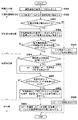
図13のフローチャートにより変形例3における改竄検知処理を説明する。なお、図13において、図9、図12に示す処理と略同等の処理には同一符号を付して、その詳細説明を省略する。 The falsification detection process in Modification 3 will be described with reference to the flowchart of FIG. In FIG. 13, the same reference numerals are given to the processes substantially the same as the processes shown in FIGS. 9 and 12, and the detailed description thereof is omitted.
上記の追加検知はステップS505とS308の間で実行される。つまり、近似領域検知部203は、改竄領域が特定されたか否かを判定し(S601)、改竄領域が特定された場合は追加検知(S602)を実行し、改竄領域を特定しなかった場合は処理をステップS308に進める。
The above additional detection is executed between steps S505 and S308. In other words, the approximate
図14のフローチャートにより追加検知の詳細を説明する。 Details of the additional detection will be described with reference to the flowchart of FIG.
近似領域検知部203は、暫定コピー先領域の周辺領域と暫定コピー元領域の周辺領域を探索範囲に設定する(S701)。そして、各周辺領域を特徴量抽出領域に分割し(S702)、二つの周辺領域の間で特徴量が一致または近似する特徴量抽出領域を探索する(S703)。特徴量が一致または近似する特徴量抽出領域を検知した場合は(S704)、検知した特徴量抽出領域をコピー先領域とコピー元領域にそれぞれ追加する(S705)。
The approximate
近似領域検知部203は、ステップS706の判定により、探索範囲のすべての特徴量抽出領域について探索を行うまで、ステップS703からS705の処理を繰り返す。
The approximate
変形例3によれば、入力画像データの全体から特徴量が一致または近似する領域を検知して同一画像内コピーによるコピーペア領域を検知する場合に比べて改竄検知処理を高速化できるとともに、検知精度の低下も防ぐことができる。 According to the third modification, the falsification detection process can be speeded up and detected as compared with the case where a copy pair region by the same in-image copy is detected by detecting a region where the feature amount matches or approximates from the entire input image data. A decrease in accuracy can also be prevented.
[変形例4]
変形例2、3では、同一画像内コピーにおける改竄領域が特定されなかった場合に不規則領域を表示する例を説明した。変形例4では、同一画像内コピーによるコピー先領域とコピー元領域に加え、検知された不規則領域のうち、同一画像内コピーにおける改竄領域として特定されなかった不規則領域を別画像コピーによる改竄領域として特定する例を説明する。
[Modification 4]
In the modified examples 2 and 3, the example in which the irregular area is displayed when the falsified area in the same image copy is not specified has been described. In the modified example 4, in addition to the copy destination area and the copy source area by the copy in the same image, the irregular area that has not been specified as the falsification area in the copy in the same image among the detected irregular areas is falsified by another image copy. An example of specifying the area will be described.
図15のフローチャートにより変形例4における改竄検知処理を説明する。なお、図15において、図9、図12に示す処理と略同等の処理には同一符号を付して、その詳細説明を省略する。
The falsification detection process in
ステップS505の後、改竄特定部204は、改竄領域として特定されなかった不規則領域があるか否かを判定し(S801)、改竄領域として特定されなかった不規則領域を別画像コピーによる改竄領域として特定する(S802)。出力部205は、コピー元領域、コピー先領域、別画像コピーによる改竄領域を識別可能に表示する(S803)。
After step S505, the
[他の変形例]
変形例1において説明した特定モード/表示モードの切り替えを、変形例2から変形例4の改竄検知処理に適用することができる。
[Other variations]
The switching of the specific mode / display mode described in the first modification can be applied to the falsification detection process in the second to fourth modifications.
また、変形例4において説明した別画像コピーによる改竄領域の特定を、実施例1、変形例1、変形例3に適用することができる。 Further, the specification of the falsified area by another image copy described in the fourth modification can be applied to the first embodiment, the first modification, and the third modification.
また、上記では、主成分分析により特徴量を取得する例を説明したが、次の特徴量を用いてもよい。例えば、SIFT (scale-invariant feature transform)やSURF (speeded up robust feature)などの特徴量である。また、近似領域検知部203は、特徴量ではなく、RGB成分値が一致または近似するかによって、同一画像内コピーによるコピーペア領域を検知することもできる。
Moreover, although the example which acquires the feature-value by a principal component analysis was demonstrated above, you may use the following feature-value. For example, feature quantities such as SIFT (scale-invariant feature transform) and SURF (speeded up robust feature). The approximate
また、上記では、不規則領域の検知にCFAを利用する例を示した。しかし、カメラにおける現像処理が不規則な領域を画像データから抽出する技術であればよく、例えば、イメージセンサに固有のノイズ(センサノイズ)を画像データから抽出して、不規則領域を検知する技術を利用することもできる。その他、現像時のエッジ処理などを行うカメラ反応関数を画像データから推測し、カメラ反応関数が不規則な領域を改竄領域として特定することもできる。 Moreover, in the above, the example which uses CFA for the detection of an irregular area was shown. However, any technique may be used as long as the development process in the camera is an irregular area extracted from the image data. For example, a technique for detecting an irregular area by extracting noise (sensor noise) specific to the image sensor from the image data. Can also be used. In addition, a camera response function for performing edge processing at the time of development can be estimated from image data, and an area where the camera response function is irregular can be specified as a falsified area.
言い替えれば、不規則領域検知部202は、入力画像データの現像処理条件を推定し、現像処理条件が乱れた領域を不規則領域として検知する。現像処理条件として、CFAパターン、DMA、デモザイキングにおいて注目画素の補間に用いる参照画素、センサノイズ、カメラ反応関数などが利用可能である。
In other words, the irregular
[その他の実施例]
また、本発明は、以下の処理を実行することによっても実現される。即ち、上述した実施形態の機能を実現するソフトウェア(プログラム)を、ネットワーク又は各種記録媒体を介してシステム或いは装置に供給し、そのシステムあるいは装置のコンピュータ(又はCPUやMPU等)がプログラムを読み出して実行する処理である。
[Other Examples]
The present invention can also be realized by executing the following processing. That is, software (program) that realizes the functions of the above-described embodiments is supplied to a system or apparatus via a network or various recording media, and a computer (or CPU, MPU, etc.) of the system or apparatus reads the program. It is a process to be executed.
Claims (17)
前記撮像データにおいて特徴量が近似する少なくとも二つの領域を近似領域として検知する第二の検知手段と、
前記不規則領域と前記近似領域に基づき、前記近似領域から前記撮像データの改竄領域を特定する特定手段とを有する画像処理装置。 A first detection means for detecting an irregular area in the imaging data as an irregular area;
A second detection means for detecting at least two regions whose feature values approximate in the imaging data as approximate regions;
An image processing apparatus comprising: a specifying unit that specifies a falsification region of the imaging data from the approximate region based on the irregular region and the approximate region.
前記特定手段は、前記ユーザ指示に従い、前記改竄領域の特定または前記改竄領域と前記コピー元領域の特定を行う請求項4に記載された画像処理装置。 And a means for inputting a user instruction for designating the operation of the specifying means.
5. The image processing apparatus according to claim 4, wherein the specifying unit specifies the falsified area or the falsified area and the copy source area in accordance with the user instruction.
所定のサイズの画像領域ごとに、前記不規則領域の特徴量に近似する領域を前記撮像データから探索する第二の検知手段と、
前記不規則領域の特徴量に近似する領域が検知された場合、当該不規則領域を前記撮像データの改竄領域として特定し、当該検知された領域を前記改竄領域のコピー元領域として特定する特定手段とを有する画像処理装置。 A first detection means for detecting an irregular area in the imaging data as an irregular area;
Second detection means for searching the imaging data for an area that approximates the feature amount of the irregular area for each image area of a predetermined size;
When a region that approximates the feature amount of the irregular region is detected, a specifying unit that specifies the irregular region as a falsified region of the imaging data and identifies the detected region as a copy source region of the falsified region An image processing apparatus.
前記出力手段は、前記ユーザ指示に従い、前記改竄領域を識別可能に表示するための情報、または、前記改竄領域と前記コピー元領域を識別可能に表示するための情報を出力する請求項9に記載された画像処理装置。 And a means for inputting a user instruction for designating the operation of the output means,
10. The output means outputs information for displaying the falsified area in an identifiable manner or information for displaying the falsified area and the copy source area in a distinguishable manner in accordance with the user instruction. Image processing apparatus.
前記撮像データにおいて特徴量が近似する少なくとも二つの領域を近似領域として検知し、
前記不規則領域と前記近似領域に基づき、前記近似領域から前記撮像データの改竄領域を特定する画像処理方法。 Detect irregular areas in the imaging data as irregular areas,
Detecting at least two regions having approximate feature quantities in the imaging data as approximate regions;
An image processing method for identifying a falsification region of the imaging data from the approximate region based on the irregular region and the approximate region.
所定のサイズの画像領域ごとに、前記不規則領域の特徴量に近似する領域を前記撮像データから探索し、
前記不規則領域の特徴量に近似する領域が検知された場合、当該不規則領域を前記撮像データの改竄領域として特定し、当該検知された領域を前記改竄領域のコピー元領域として特定する画像処理方法。 Detect irregular areas in the imaging data as irregular areas,
For each image area of a predetermined size, an area that approximates the feature amount of the irregular area is searched from the imaging data,
Image processing that identifies an irregular region as a falsified region of the imaging data when a region that approximates the feature amount of the irregular region is detected, and identifies the detected region as a copy source region of the falsified region Method.
Priority Applications (2)
| Application Number | Priority Date | Filing Date | Title |
|---|---|---|---|
| JP2013133097A JP6163029B2 (en) | 2013-06-25 | 2013-06-25 | Image processing apparatus and method |
| US14/298,151 US9805433B2 (en) | 2013-06-25 | 2014-06-06 | Image processing apparatus and method therefor |
Applications Claiming Priority (1)
| Application Number | Priority Date | Filing Date | Title |
|---|---|---|---|
| JP2013133097A JP6163029B2 (en) | 2013-06-25 | 2013-06-25 | Image processing apparatus and method |
Publications (3)
| Publication Number | Publication Date |
|---|---|
| JP2015007916A JP2015007916A (en) | 2015-01-15 |
| JP2015007916A5 JP2015007916A5 (en) | 2016-08-04 |
| JP6163029B2 true JP6163029B2 (en) | 2017-07-12 |
Family
ID=52110979
Family Applications (1)
| Application Number | Title | Priority Date | Filing Date |
|---|---|---|---|
| JP2013133097A Active JP6163029B2 (en) | 2013-06-25 | 2013-06-25 | Image processing apparatus and method |
Country Status (2)
| Country | Link |
|---|---|
| US (1) | US9805433B2 (en) |
| JP (1) | JP6163029B2 (en) |
Families Citing this family (5)
| Publication number | Priority date | Publication date | Assignee | Title |
|---|---|---|---|---|
| JP6198486B2 (en) * | 2012-08-29 | 2017-09-20 | キヤノン株式会社 | Image processing apparatus and method |
| US9934434B2 (en) | 2016-06-30 | 2018-04-03 | Honeywell International Inc. | Determining image forensics using an estimated camera response function |
| US10586152B2 (en) | 2017-02-16 | 2020-03-10 | Honeywell International Inc. | Determining image forensics using gradient statistics at edges |
| US11288537B2 (en) | 2019-02-08 | 2022-03-29 | Honeywell International Inc. | Image forensics using non-standard pixels |
| US11039205B2 (en) * | 2019-10-09 | 2021-06-15 | Sony Interactive Entertainment Inc. | Fake video detection using block chain |
Family Cites Families (5)
| Publication number | Priority date | Publication date | Assignee | Title |
|---|---|---|---|---|
| AU2002354326A1 (en) * | 2001-12-03 | 2003-06-17 | Fuso Precision Co., Ltd. | Digital data false alteration detection program and digital data false alteration detection apparatus |
| JP2005151345A (en) * | 2003-11-18 | 2005-06-09 | Sony Corp | Data processing device, its method, and imaging device |
| JP4771540B2 (en) * | 2006-07-26 | 2011-09-14 | キヤノン株式会社 | Image processing apparatus, control method therefor, image processing method and program |
| JP5341615B2 (en) * | 2008-06-27 | 2013-11-13 | キヤノン株式会社 | Information processing apparatus and control method thereof |
| JP6105950B2 (en) * | 2012-02-27 | 2017-03-29 | キヤノン株式会社 | Image processing apparatus and method |
-
2013
- 2013-06-25 JP JP2013133097A patent/JP6163029B2/en active Active
-
2014
- 2014-06-06 US US14/298,151 patent/US9805433B2/en active Active
Also Published As
| Publication number | Publication date |
|---|---|
| JP2015007916A (en) | 2015-01-15 |
| US9805433B2 (en) | 2017-10-31 |
| US20140376812A1 (en) | 2014-12-25 |
Similar Documents
| Publication | Publication Date | Title |
|---|---|---|
| JP6163029B2 (en) | Image processing apparatus and method | |
| JP6259188B2 (en) | Image processing apparatus and method | |
| US9798952B2 (en) | Image processing apparatus and method therefor | |
| EP1569170A1 (en) | Characteristic region extraction device, characteristic region extraction method, and characteristic region extraction program | |
| US9159112B2 (en) | Digital watermarking using saturation patterns | |
| JP6105950B2 (en) | Image processing apparatus and method | |
| US20130170756A1 (en) | Edge detection apparatus, program and method for edge detection | |
| KR20150027011A (en) | Method and apparatus for image processing | |
| CN107622497A (en) | Image cropping method, apparatus, computer-readable recording medium and computer equipment | |
| JP2017518546A (en) | Image processing method and image processing system | |
| CN108174173B (en) | Photographing method and apparatus, computer-readable storage medium, and computer device | |
| JP2012022652A (en) | Image processing apparatus, image processing method and program | |
| JP5355190B2 (en) | Image display apparatus and method, and program | |
| JP2010035143A5 (en) | Information processing apparatus and control method thereof | |
| JP2011059733A (en) | Image retrieval device and image retrieval method | |
| KR20200106854A (en) | Pixel correction | |
| JP2015138448A (en) | Image processor, image processing method, and program | |
| JP2004171375A (en) | Image processing method | |
| JP7485356B2 (en) | Crack detection method, crack detection device and program | |
| US20140184811A1 (en) | Image processing apparatus, image processing method, and computer program product | |
| JP2017073071A (en) | Identity determination program, identity determination device, and identity determination method | |
| KR101229376B1 (en) | Method and apparatus for identifying source camera by detecting interpolaton pattern used in lens distortion correction | |
| JP6292708B2 (en) | A method for obtaining parameters for traffic volume estimation from image information | |
| JP5539561B2 (en) | Image processing apparatus and method | |
| JP2014153866A (en) | Image processing system, control method and control program of the same |
Legal Events
| Date | Code | Title | Description |
|---|---|---|---|
| A521 | Written amendment |
Free format text: JAPANESE INTERMEDIATE CODE: A523 Effective date: 20160617 |
|
| A621 | Written request for application examination |
Free format text: JAPANESE INTERMEDIATE CODE: A621 Effective date: 20160617 |
|
| A977 | Report on retrieval |
Free format text: JAPANESE INTERMEDIATE CODE: A971007 Effective date: 20170511 |
|
| TRDD | Decision of grant or rejection written | ||
| A01 | Written decision to grant a patent or to grant a registration (utility model) |
Free format text: JAPANESE INTERMEDIATE CODE: A01 Effective date: 20170519 |
|
| A61 | First payment of annual fees (during grant procedure) |
Free format text: JAPANESE INTERMEDIATE CODE: A61 Effective date: 20170616 |
|
| R151 | Written notification of patent or utility model registration |
Ref document number: 6163029 Country of ref document: JP Free format text: JAPANESE INTERMEDIATE CODE: R151 |