JP6161962B2 - Audio signal reproduction apparatus and method - Google Patents
Audio signal reproduction apparatus and method Download PDFInfo
- Publication number
- JP6161962B2 JP6161962B2 JP2013119366A JP2013119366A JP6161962B2 JP 6161962 B2 JP6161962 B2 JP 6161962B2 JP 2013119366 A JP2013119366 A JP 2013119366A JP 2013119366 A JP2013119366 A JP 2013119366A JP 6161962 B2 JP6161962 B2 JP 6161962B2
- Authority
- JP
- Japan
- Prior art keywords
- signal
- sound image
- sound
- speaker
- unit
- Prior art date
- Legal status (The legal status is an assumption and is not a legal conclusion. Google has not performed a legal analysis and makes no representation as to the accuracy of the status listed.)
- Expired - Fee Related
Links
Images


Description
本発明は、音声信号を再生する音声信号再生装置及び方法に関する。 The present invention relates to an audio signal reproduction apparatus and method for reproducing an audio signal.
従来から提案されている音響再生方式には、ステレオ(2ch)方式、5.1chサラウンド方式(ITU−R BS.775−1)、7.1ch、9.1ch、22.2chなどのマルチチャネル再生方式や、音源オブジェクト指向再生方式がある。後者の方式は、全ての音が、いずれかの音源オブジェクトが発する音であるとする方式であり、各音源オブジェクト(以下、「仮想音源」と呼ぶ。)が自身の位置情報と音声信号とを含んでいる。音楽コンテンツを例にとると、各仮想音源は、それぞれの楽器の音と楽器が配置されている位置情報とを含む。 Conventionally proposed sound reproduction methods include multi-channel reproduction such as stereo (2ch) method, 5.1ch surround method (ITU-R BS.775-1), 7.1ch, 9.1ch, 22.2ch, etc. And a sound source object-oriented reproduction method. The latter method is a method in which all sounds are sounds emitted by any sound source object, and each sound source object (hereinafter referred to as “virtual sound source”) has its own position information and audio signal. Contains. Taking music content as an example, each virtual sound source includes the sound of each musical instrument and position information where the musical instrument is arranged.
音源オブジェクト指向再生方式は、通常、直線状あるいは面状に並べたスピーカ群によって音の波面を合成する再生方式(すなわち波面合成再生方式)により再生される。このような波面合成再生方式のうち、非特許文献1に記載のWave Field Synthesis(WFS)方式は、直線状あるいは曲線上に並べたスピーカ群(以下、スピーカアレイという)を用いる現実的な実装方法の1つとして近年盛んに研究されている。
The sound source object-oriented reproduction method is usually reproduced by a reproduction method (that is, a wavefront synthesis reproduction method) in which a sound wavefront is synthesized by a group of speakers arranged in a straight line or a plane. Among such wavefront synthesis reproduction systems, the Wave Field Synthesis (WFS) system described in
このような波面合成再生方式は、スイートスポットが狭い上述のマルチチャネル再生方式とは異なり、並べられたスピーカ群の前のどの位置で聴いている受聴者に対しても、良好な音像と音質を両方同時に提示することができるという特長を持つ。つまり、波面合成再生方式でのスイートスポットは幅広くなっている。 Such a wavefront synthesis playback system, unlike the above-mentioned multi-channel playback system with a narrow sweet spot, provides a good sound image and sound quality for listeners listening at any position in front of the arranged speaker groups. It has the feature that both can be presented simultaneously. That is, the sweet spot in the wavefront synthesis reproduction method is wide.
特許文献1には、通常、映画コンテンツなどに使用されている5.1chの音声信号を複数のチャネルの音声信号に変換して波面合成再生方式で再生する再生方法が提案されている。具体的には、左フロントチャネル信号、右フロントチャネル信号、センターチャネル信号、左リアチャネル信号、右リアチャネル信号、サブウーファーチャネル信号のうち、左フロントチャネル信号と右フロントチャネル信号とに着目して相関信号成分と無相関信号成分とに分離し、相関信号成分を複数の仮想音源に割り当てた上で、中心の仮想音源にセンターチャネル信号を重畳することにより、5.1chの音声信号を波面合成再生方式で再生している。
ところで、従来から、音響システムやオーディオソフトウェアにおいて、音楽に連動させ視覚的な表示を変化させ、没入感を増加させるような技術が様々提案されている。例えば、ある一定の周波数帯域毎に、音圧のパワーの絶対値を棒グラフとして表示させる方式や、音の時間的な変化によって色や図形をランダムに変化させて表示させる方式などが挙げられる。 By the way, conventionally, various technologies have been proposed in acoustic systems and audio software that change visual display in conjunction with music to increase the immersive feeling. For example, there are a method of displaying the absolute value of the sound pressure power as a bar graph for each certain frequency band, a method of displaying colors and figures at random according to temporal changes in sound, and the like.
その他、音圧レベルの表示を音像位置と連動させ、空間的な音像位置を視覚化する方式も提案されている(例えば、特許文献2を参照)。特許文献2に記載の方式では、左右の音声信号のレベル差の絶対値のみで音像位置を判断している。よって、左右の音声信号が振幅のみ異なる場合、もしくは振幅も同一である場合には、知覚上の音像位置と表示位置が一致することになる。 In addition, a method of visualizing the spatial sound image position by linking the display of the sound pressure level with the sound image position has been proposed (see, for example, Patent Document 2). In the method described in Patent Document 2, the sound image position is determined only by the absolute value of the level difference between the left and right audio signals. Therefore, if the left and right audio signals differ only in amplitude, or if the amplitudes are also the same, the perceptual sound image position matches the display position.
しかしながら、特許文献2に記載の方式では、左右の音声信号のレベル差の絶対値のみで音像位置を判断する方式であるため、音像が左右のどちらに寄っているかというような情報は表示されない。 However, in the method described in Patent Document 2, since the sound image position is determined based only on the absolute value of the level difference between the left and right audio signals, information indicating whether the sound image is closer to the left or right is not displayed.
また、通常の音楽コンテンツなどにおいては、それぞれの音像位置が異なるようにミキシングされたボーカルや各楽器の音が混ざり合っており、それぞれの構成音毎に音像が異なるが、特許文献2に記載の方式では、音像位置は代表値で表示されることになるため、聴覚と知覚で音像位置が一致しないことになる。 Also, in normal music content, vocals mixed with different sound image positions and sounds of each instrument are mixed, and the sound image differs for each component sound. In the method, since the sound image position is displayed as a representative value, the sound image position does not match between hearing and perception.
さらに、左右で異なる音声信号が入力されている場合、知覚上、音像は生じないはずであるが、特許文献2に記載の方式では、左右の音声信号のレベル差の絶対値のみで音像位置を判断するため、いずれかの場所に音像が表示されてしまい、聴覚と知覚とで音像位置が一致しないことになる。 Furthermore, when different audio signals are input to the left and right, a sound image should not be generated for perception, but in the method described in Patent Document 2, the position of the sound image is determined only by the absolute value of the level difference between the left and right audio signals. Therefore, a sound image is displayed at any location, and the sound image position does not match between hearing and perception.
本発明は、上述のような実情に鑑みてなされたものであり、その目的は、聴覚と知覚とで音像位置が一致するように音像位置を表示させることが可能な音声信号再生装置及び音声信号再生方法を提供することにある。 The present invention has been made in view of the above situation, and an object of the present invention is to provide an audio signal reproduction device and an audio signal capable of displaying a sound image position so that the sound image position matches between hearing and perception. It is to provide a reproduction method.
上記の課題を解決するために、本発明の第1の技術手段は、音声信号再生装置であって、2つの音声信号を、周波数毎または周波数帯域毎に周波数についての相関信号と無相関信号とに分離する分離部と、該分離部で分離された各相関信号について、音像方向及び信号電力値を算出する算出部と、各相関信号について、前記音像方向に基づき、予め定められた複数の音像方向グループのうちの1つに前記信号電力値を割り当て、該音像方向グループ毎に前記信号電力値の加算値を求める加算部と、前記複数の音像方向グループのそれぞれに対応する位置に各音像方向グループについての前記加算値を示す情報を表示する音像表示部と、を備えたことを特徴としたものである。 In order to solve the above-mentioned problem, a first technical means of the present invention is an audio signal reproduction device, comprising two audio signals, a correlation signal and a non-correlation signal for each frequency or frequency band. A separation unit that separates the correlation signals, a calculation unit that calculates a sound image direction and a signal power value for each correlation signal separated by the separation unit, and a plurality of predetermined sound images based on the sound image direction for each correlation signal An adder that assigns the signal power value to one of the direction groups and obtains an added value of the signal power value for each sound image direction group, and each sound image direction at a position corresponding to each of the plurality of sound image direction groups And a sound image display unit for displaying information indicating the added value of the group.
本発明の第2の技術手段は、第1の技術手段において、前記音像表示部は、棒グラフ形式で、前記複数の音像方向グループのそれぞれに対応する位置に各音像方向グループについての前記加算値を示す情報を表示することを特徴としたものである。 According to a second technical means of the present invention, in the first technical means, the sound image display unit displays the addition value for each sound image direction group in a bar graph format at a position corresponding to each of the plurality of sound image direction groups. The information to be displayed is displayed.
本発明の第3の技術手段は、第1の技術手段において、前記音像表示部は、複数の発光部を有し、前記複数の音像方向グループのそれぞれに対応する位置の前記発光部の発光色を、各音像方向グループについての前記加算値を示す情報に応じて変化させることを特徴としたものである。 According to a third technical means of the present invention, in the first technical means, the sound image display unit includes a plurality of light emitting units, and the emission color of the light emitting unit at a position corresponding to each of the plurality of sound image direction groups. Is changed according to information indicating the added value for each sound image direction group.
本発明の第4の技術手段は、第1の技術手段において、前記音像表示部は、複数の発光部を有し、前記複数の音像方向グループのそれぞれに対応する位置の前記発光部の発光強度を、各音像方向グループについての前記加算値を示す情報に応じて変化させることを特徴としたものである。 According to a fourth technical means of the present invention, in the first technical means, the sound image display unit includes a plurality of light emitting units, and the light emission intensity of the light emitting unit at a position corresponding to each of the plurality of sound image direction groups. Is changed according to information indicating the added value for each sound image direction group.
本発明の第5の技術手段は、音声信号再生方法であって、分離部が、2つの音声信号を、周波数毎または周波数帯域毎に周波数についての相関信号と無相関信号とに分離する分離ステップと、算出部が、前記分離ステップで分離された各相関信号について、音像方向及び信号電力値を算出する算出ステップと、加算部が、各相関信号について、前記音像方向に基づき、予め定められた複数の音像方向グループのうちの1つに前記信号電力値を割り当て、該音像方向グループ毎に前記信号電力値の加算値を求める加算ステップと、音像表示部が、前記複数の音像方向グループのそれぞれに対応する位置に各音像方向グループについての前記加算値を示す情報を表示する音像表示ステップと、を含むことを特徴としたものである。 According to a fifth technical means of the present invention, there is provided an audio signal reproducing method, wherein the separation unit separates the two audio signals into a correlated signal and a non-correlated signal for each frequency or frequency band. And a calculation unit that calculates a sound image direction and a signal power value for each correlation signal separated in the separation step, and an addition unit is predetermined based on the sound image direction for each correlation signal. An addition step of assigning the signal power value to one of a plurality of sound image direction groups and obtaining an addition value of the signal power values for each sound image direction group; and a sound image display unit, And a sound image display step for displaying information indicating the added value for each sound image direction group at a position corresponding to the sound image direction group.
本発明によれば、音声信号再生装置において、聴覚と知覚とで音像位置が一致するように音像位置を表示させることが可能になる。 According to the present invention, in the audio signal reproduction device, it is possible to display the sound image position so that the sound image position matches between hearing and perception.
本発明に係る音声信号再生装置は、2チャネル以上のマルチチャネル再生方式用の音声信号を、そのまま対応するスピーカ群から出力するか、もしくは、波面合成再生方式などの他の再生方式でスピーカ群からより適切な音像を提供できるような音声信号に変換してから出力する装置であり、後述するような音像表示処理を行う点に特徴を有する。本発明に係る音声信号再生装置は、音声再生処理と音像表示処理が実行可能なように構成すればよく、例えば、テレビ装置等の表示装置やオーディオシステムなど、様々なAV(Audio Visual)機器として構成することができる。 The audio signal reproduction apparatus according to the present invention outputs an audio signal for a multi-channel reproduction method of two or more channels as it is from a corresponding speaker group, or from the speaker group by another reproduction method such as a wavefront synthesis reproduction method. This is an apparatus that outputs the sound signal after converting it into a sound signal that can provide a more appropriate sound image, and is characterized in that it performs a sound image display process as described later. The audio signal reproduction device according to the present invention may be configured to be able to execute audio reproduction processing and sound image display processing. For example, as various AV (Audio Visual) devices such as a display device such as a television device and an audio system. Can be configured.
音声再生機能に関しては、以下では基本的に、波面合成再生方式により2つ以上のチャネルの入力音声信号を仮想音源に対する音像としてスピーカ群(複数のスピーカ)により再生させるための音声信号に変換して再生する場合を例に挙げて説明する。以下では特に、仮想音源の数と同数・同位置の再生用スピーカを用意して、各仮想音源から出力すべき音声信号を、一対一で対応する再生用スピーカから再生するような場合について説明する。 Regarding the audio playback function, below, basically, the input audio signals of two or more channels are converted into audio signals to be reproduced by a speaker group (a plurality of speakers) as a sound image for a virtual sound source by the wavefront synthesis playback method. A case of reproduction will be described as an example. In the following, a case will be described in which playback speakers having the same number and the same positions as the number of virtual sound sources are prepared, and audio signals to be output from the respective virtual sound sources are played back one-to-one from the corresponding playback speakers. .
ただし、スピーカの数や位置が仮想音源のそれらと異なるように仮想音源が設定される場合にも、各仮想音源からスピーカ群への割り当てを行うことで、同様に適用できる。また、上述したように、入力された音声信号をそのまま音声出力するような構成を採用することもできる。なお、この場合にも、本発明に係る音像表示処理のための処理、例えば音声信号の分離抽出までの処理は必要となる。 However, even when the virtual sound source is set so that the number and position of the speakers are different from those of the virtual sound source, it can be similarly applied by assigning each virtual sound source to the speaker group. Further, as described above, it is possible to adopt a configuration in which an input audio signal is output as it is. In this case as well, processing for sound image display processing according to the present invention, for example, processing up to separation and extraction of audio signals is necessary.
以下、図面を参照しながら、本発明に係る音声信号再生装置の構成例及び処理例について説明する。図1は、本発明に係る音声信号再生装置の一構成例を示すブロック図で、図2は、図1の音声信号再生装置における音声信号処理部の一構成例を示すブロック図である。 Hereinafter, a configuration example and a processing example of an audio signal reproduction device according to the present invention will be described with reference to the drawings. FIG. 1 is a block diagram illustrating a configuration example of an audio signal reproduction device according to the present invention, and FIG. 2 is a block diagram illustrating a configuration example of an audio signal processing unit in the audio signal reproduction device of FIG.
図1で例示する音声信号再生装置(音声データ再生装置)10は、デコーダ11、音声信号抽出部12、音声信号処理部13を備えるとともに、D/Aコンバータ14、複数の増幅器15、及び複数のスピーカ16でなるスピーカアレイ17を備える。なお、増幅器15とスピーカ16の数は基本的に同じとする。また、音声信号再生装置10は、音像表示処理のために表示制御部18及び表示部19を備える。
An audio signal reproduction device (audio data reproduction device) 10 illustrated in FIG. 1 includes a decoder 11, an audio
デコーダ11は、音声のみあるいは音声付き映像のコンテンツを復号化し、信号処理可能な形式に変換し音声信号抽出部12に出力する。そのコンテンツは、放送局から送信されたデジタル放送のコンテンツや、ネットワークを介してディジタルコンテンツを配信するサーバからインターネットからダウンロードしたり、あるいは外部記憶装置等の記録媒体から読み込んだりすることによって取得する。このように、図1では図示しないが、音声信号再生装置10は、マルチチャネルの入力音声信号を含むディジタルコンテンツを入力するディジタルコンテンツ入力部を備える。デコーダ11は、ここで入力されたディジタルコンテンツを復号化することになる。
The decoder 11 decodes the content of audio only or video with audio, converts it into a signal processable format, and outputs it to the audio
音声信号抽出部12では、得られた信号から音声信号を分離、抽出する。ここで説明する例では、抽出する音声信号を2chステレオ信号とし、音声信号抽出部12はその2チャネル分の信号を音声信号処理部13に出力する。無論、元々入力された信号が2chステレオ信号である場合には、音声信号抽出部12では、その2chステレオ信号を抽出すれば済む。
The audio
一方で、例えば入力音声信号が5.1chなど、2chを越えるチャネル数である場合には、音声信号抽出部12は、例えばARIB STD−B21「デジタル放送用受信装置 標準規格」によって定められているような、次の数式(1)の通常のダウンミックス方法によって2chにダウンミックスし、音声信号処理部13に出力する。
On the other hand, for example, when the input audio signal has a channel number exceeding 2 ch, such as 5.1 ch, the audio

数式(1)で、Lt、Rtはダウンミックス後の左右チャネル信号、L、R、C、LS、RSはそれぞれ5.1chの各信号(左フロントチャネル信号、右フロントチャネル信号、センターチャネル信号、左リアチャネル信号、右リアチャネル信号)、aはオーバーロード低減係数で例えば1/√2、kdはダウンミックス係数で例えば1/√2、または1/2、または1/2√2、または0となる。 In Equation (1), L t and R t are left and right channel signals after downmixing, and L, R, C, L S and R S are 5.1ch signals (left front channel signal, right front channel signal, Center channel signal, a left rear channel signal, the right rear channel signal), a overload reduction factor, for example, 1 / √2, k d is, for example, 1 / √2 downmix coefficients or 1/2, or 1/2, √2 or 0.
このように、マルチチャネルの入力音声信号は、3以上のチャネルをもつマルチチャネル再生方式の入力音声信号であってもよく、その場合、音声信号処理部13では、マルチチャネルの入力音声信号を2つのチャネルの音声信号にダウンミックスした後の2つのチャネルの音声信号について、後述の音像表示処理の対象としてもよい。もしくは、3以上のチャネルをもつマルチチャネル再生方式の入力音声信号から単に2つのチャネルの音声信号を抽出して、その2つのチャネルの音声信号についてのみ、後述の音像表示処理の対象としてもよい。
As described above, the multi-channel input audio signal may be an input audio signal of a multi-channel reproduction method having three or more channels. In this case, the audio
音声信号処理部13では、得られた2チャネル信号から、音声再生処理の一部として、入力音声信号とは異なるマルチチャネル(好ましくは5チャネル以上)の音声信号を生成する。
The audio
音声信号処理部13は、それらの音声信号をD/Aコンバータ14に出力する。D/Aコンバータ14では得られた信号をアナログ信号に変換し、それぞれの信号を増幅器15に出力する。各増幅器15では入力されたアナログ信号を拡声し各スピーカ16に伝送し、この拡声されたアナログ信号が各スピーカ16から空間中に音として出力される。
The audio
スピーカアレイ17において、スピーカ16は一列または複数列に配置されており、その1つ1つの形状は円形や楕円形や菱形などどのような形状であってもよい。また、配列の方向も直線状に限らず、曲線状に各スピーカ16の中心を配列しておいてもよい。なお、音声信号処理部13では、スピーカアレイ17における各スピーカ16の配置に応じて各スピーカ16に対する遅延量や出力レベルを決定すればよい。
In the
さらに、音声信号処理部13では、本発明の主たる特徴である音像表示処理の一部として、上記得られた2チャネル信号から音像方向情報を生成する。音像方向情報とは、周波数毎(線スペクトル毎)または周波数帯域毎(周波数領域毎)についての、音像の推定方向角(音像方向を示す値)とその信号成分の電力値(信号電力値)を指す。音声信号処理部13は、線スペクトル毎または周波数帯域毎に生成した音像方向情報を表示制御部18に出力する。
Further, the audio
表示制御部18は、音像表示のための情報を求める加算部18aを有する。この加算部18aは、各相関信号について、算出された音像方向に基づき、予め定められた複数の音像方向グループ(音像方向範囲)のうちの1つに算出された信号電力値を割り当て、音像方向グループ毎に信号電力値の加算値を求める。表示制御部18は、加算部18aで求めた音像方向グループ毎の加算値を表示部19に出力する。
The
表示部19は、音像表示部の一例であり、音像表示部は、上記複数の音像方向グループのそれぞれに対応する位置(好ましくは各音像方向グループの中央の方向のと一致する位置)に各音像方向グループについての加算値を示す情報を表示する。具体的な表示例については後述する。音像方向グループ毎の信号電力値は、表示対象となる2チャネル信号により時系列で変化しており、表示部19ではそのような変化に合わせて音像方向の表示を変化させることができる。このように、本発明では、聴覚と知覚とで音像位置が一致するように音像位置を表示させることができ、受聴者の没入感を高めることができる。
The
以下、音声再生処理及び音像表示処理を行う音声信号処理部13の詳細な構成例を、図2を参照しながら説明する。音声信号処理部13は、変換部21、分離抽出部22、逆変換部23、及び音声出力信号生成部24を備える。
Hereinafter, a detailed configuration example of the audio
変換部21は、入力された2つのチャネルの入力信号それぞれを、1セグメントの1/4の長さの音声データ分読み出す。ここで、音声データとは、例えば48kHzなどの標本化周波数で標本化された離散音声信号波形を指すものとする。そして、セグメントとは、ある一定の長さの標本点群からなる音声データ区間であり、ここでは後ほど離散フーリエ変換の対象となる区間長を指すものとし、処理セグメントとも呼ぶ。その値は例えば1024とする。この例では、1セグメントの1/4の長さである256点の音声データが読み出し対象となる。
The
読み出した256点の音声データはバッファに蓄えられる。このバッファは、直前の1セグメント分の音声信号波形を保持しておけるようになっており、それより過去のセグメントは捨てていく。直前の3/4セグメント分のデータ(768点)と最新の1/4セグメント分のデータ(256点)を繋げて1セグメント分の音声データを作成し、窓関数を乗算する。すなわち、全ての標本データは窓関数演算に4回読み込まれることになる。 The read out 256-point audio data is stored in the buffer. This buffer can hold the sound signal waveform for the immediately preceding segment, and the past segments are discarded. Audio data for one segment is created by connecting the previous 3/4 segment data (768 points) and the latest 1/4 segment data (256 points), and is multiplied by a window function. That is, all sample data is read four times in the window function calculation.
ここで、窓関数の乗算とは、従来提案されている次のHann窓を1セグメント分の音声データに乗算する窓関数演算処理を実行する。
mは自然数、Mは1セグメント長で偶数とする。変換部21への入力信号をそれぞれxL(m)、xR(m)とすると、窓関数乗算後の音声信号x′L(m)、x′R(m)は、
x′L(m)=w(m)xL(m)、
x′R(m)=w(m)xR(m) (3)
と計算される。
m is a natural number, M is a segment length and an even number. Assuming that the input signals to the
x ′ L (m) = w (m) × L (m),
x ′ R (m) = w (m) × R (m) (3)
Is calculated.
変換部21は、そうして得られた音声データを、次の数式(4)のように離散フーリエ変換し、周波数領域の音声データを得る。つまり、変換部21は、2つのチャネル(の音声データ)に対し、離散フーリエ変換を施す。ここで、DFTは離散フーリエ変換を表し、kは自然数で、0<k≦M/2である。XL(k)、XR(k)は複素数となる。
XL(k)=DFT(x′L(m))、
XR(k)=DFT(x′R(m)) (4)
The
X L (k) = DFT (x ′ L (m)),
X R (k) = DFT (x ′ R (m)) (4)
分離抽出部22は、線スペクトル毎(つまり周波数毎)に、変換部21で変換された2つのチャネルについて、相関信号と無相関信号を分離(抽出)する。以下では、分離抽出部22のうちこのような分離(抽出)を行う部位を、分離部22aとして説明する。つまり、分離部22aは2つの音声信号を、周波数毎(または周波数帯域毎)に相関信号と無相関信号とに分離する。ここで相関信号とは、周波数について相関する信号を指し、無相関信号とは周波数について相関しない信号を指す。
The separation /
また、分離抽出部22は、音像表示処理のための算出部22bを有し、この算出部22bは、分離部22aで分離された各相関信号について、音像方向及び信号電力値を算出する。より具体的には、算出部22bは、線スペクトル毎に、その相関信号の音像方向の角度の推定を行うと共に、その相関信号の信号電力値を求める。なお、算出部22bは、以下に説明する例のように音声再生処理において音像方向及び信号電力値が必要な場合には、音像表示処理と音声再生処理の双方の処理を兼ねることになる。音声再生処理に音像方向及び信号電力値が必要ない場合としては、上述したように、入力された音声信号をそのまま音声出力するような構成が挙げられる。
The separation /
また、分離部22aにおいては、線スペクトル毎でなくても周波数帯域(小帯域)毎に相関信号と無相関信号とを分離、抽出してもよく、その場合、算出部22bでの音像方向及び信号電力値の算出も小帯域毎の相関信号についての算出となる。つまり、ここでは線スペクトル毎に相関係数を取得するなどの処理を行う例を挙げて説明するが、特許文献1に記載のように、Equivalent Rectangular Band(ERB)を用いて分割した帯域(周波数領域であり、小帯域とも呼ぶ)毎に相関係数を取得するなどの処理を実行してもよい。
Further, the
算出部22bでの算出後は、加算部18aが、その推定角度に基づいて、相関信号を方向毎に分離(グループ分け)し、各音像方向グループに属する相関信号の信号電力値について加算値を求める。そして、表示部19が、音像方向グループと加算値を示す情報とを関連付けて表示する。
After the calculation by the
分離抽出部22における処理の具体的な内容を、図3を用いて説明する。分離抽出部22は、変換部21で離散フーリエ変換後の2つのチャネルの音声信号について、線スペクトル毎にステップS32〜S34の処理を実行する(ステップS31a,S31b。具体的に個々の処理について説明する。
The specific contents of the processing in the separation /
離散フーリエ変換した後の線スペクトルは、直流成分すなわち例えばXL(0)を除いて、M/2(ただし、Mは偶数)を境に対称となっている。すなわち、XL(k)とXL(M−k)は0<k<M/2の範囲で複素共役の関係になる。したがって、以下ではk≦M/2の範囲を分析の対象として考え、k>M/2の範囲については複素共役の関係にある対称の線スペクトルと同じ扱いとする。 The line spectrum after the discrete Fourier transform is symmetrical with respect to M / 2 (where M is an even number) except for the DC component, that is, X L (0), for example. That is, X L (k) and X L (M−k) have a complex conjugate relationship in the range of 0 <k <M / 2. Therefore, in the following, the range of k ≦ M / 2 is considered as the object of analysis, and the range of k> M / 2 is treated the same as a symmetric line spectrum having a complex conjugate relationship.
次に、各線スペクトルに対し、左チャネルと右チャネルの正規化相関係数を次式で求めることで、相関係数を取得する。ここで、対象となる線スペクトルの音声信号Xのゲイン(振幅)をGとすると、P(X)は、音声信号Xの電力(音圧に相当)を表し、ゲインGの二乗値で表現できる。 Next, the correlation coefficient is acquired by calculating | requiring the normalization correlation coefficient of the left channel and the right channel with following Formula with respect to each line spectrum. Here, when the gain (amplitude) of the audio signal X of the target line spectrum is G, P (X) represents the power (corresponding to the sound pressure) of the audio signal X and can be expressed by the square value of the gain G. .
この正規化相関係数d(k)は左右のチャネルの音声信号にどれだけ相関があるかを表すものであり、0から1の間の実数の値をとる。全く同じ信号同士であれば1、そして全く無相関の信号同士であれば0となる。ここで、左右のチャネルの音声信号の電力PL (k)とPR (k)の両方が0である場合、その線スペクトルに関して相関信号と無相関信号の抽出は不可能とし、処理を行わず次の線スペクトルの処理に移ることとする。また、PL (k)とPR (k)のいずれか片方が0である場合、数式(5)では演算不可能であるが、正規化相関係数d(k)=0とし、その線スペクトルの処理を続行する。 This normalized correlation coefficient d (k) represents how much the audio signals of the left and right channels are correlated, and takes a real value between 0 and 1. 1 if the signals are exactly the same, and 0 if the signals are completely uncorrelated. Here, when both the powers P L (k) and P R (k) of the audio signals of the left and right channels are 0, it is impossible to extract the correlated signal and the uncorrelated signal with respect to the line spectrum, and processing is performed. Let's move on to the processing of the next line spectrum. Also, if either one of P L (k) or P R (k) is 0, the calculation cannot be performed using Equation (5), but the normalized correlation coefficient d (k) = 0 and the line Continue processing the spectrum.
次に、この正規化相関係数d(k)を用いて、左右チャネルの音声信号から相関信号と無相関信号をそれぞれ分離抽出するための変換係数を求め(ステップS32)、ステップS32で取得したそれぞれの変換係数を用いて、左右チャネルの音声信号から相関信号と無相関信号を分離抽出する(ステップS33)。相関信号及び無相関信号は、いずれも推定した音声信号として抽出すればよい。ステップS32,S33の処理は、主に分離抽出部22のうち分離部22aが担えばよいが、算出部22bにおける処理も兼ねている。
Next, using this normalized correlation coefficient d (k) , a conversion coefficient for separating and extracting the correlation signal and the non-correlation signal from the left and right channel audio signals is obtained (step S32), and obtained in step S32. Using each conversion coefficient, a correlation signal and a non-correlation signal are separated and extracted from the audio signals of the left and right channels (step S33). What is necessary is just to extract both a correlation signal and a non-correlation signal as the estimated audio | voice signal. The processing in steps S32 and S33 may be performed mainly by the
ステップS32,S33の処理例を説明する。ここで、特許文献1と同様、左右チャネルそれぞれの信号は、無相関信号と相関信号から構成され、相関信号については、左右のチャネルからゲインのみ異なる信号波形(つまり同じ周波数成分からなる信号波形)が出力されるものとするモデルを採用する。ここで、ゲインは、信号波形の振幅に相当し、音圧に関連する値である。そして、このモデルでは、左右のチャネル信号から出力される相関信号によって合成される音像は、その相関信号の左右それぞれの音圧のバランスによって方向が決定されるものとする。
A processing example of steps S32 and S33 will be described. Here, as in
そのモデルに従うと、入力信号xL(m)、xR(m)は、
xL(m)= s(m)+nL(m)、
xR(m)=αs(m)+nR(m) (9)
と表される。ここで、s(m)は左右の相関信号、nL(m)は左チャネルの音声信号から相関信号s(m)を減算したものであって(左チャネルの)無相関信号として定義できるもの、nR(m)は右チャネルの音声信号から相関信号s(m)にαを乗算したものを減算したものであって(右チャネルの)無相関信号として定義できるものである。また、αは相関信号の左右の音圧バランスの程度を表す正の実数である。
According to the model, the input signals x L (m), x R (m) are
x L (m) = s (m) + n L (m),
x R (m) = αs (m) + n R (m) (9)
It is expressed. Here, s (m) is a left and right correlation signal, n L (m) is a subtracted correlation signal s (m) from a left channel audio signal, and can be defined as an uncorrelated signal (left channel). , N R (m) is obtained by subtracting the correlation signal s (m) multiplied by α from the right channel audio signal, and can be defined as an uncorrelated signal (right channel). Α is a positive real number representing the degree of left and right sound pressure balance of the correlation signal.
数式(9)により、数式(3)で前述した窓関数乗算後の音声信号x′L(m)、x′R(m)は、次の数式(10)で表される。ただし、s′(m)、n′L(m)、n′R(m)はそれぞれs(m)、nL(m)、nR(m)に窓関数を乗算したものである。
x′L(m)=w(m){s(m)+nL(m)}=s′(m)+n′L(m)、
x′R(m)=w(m){αs(m)+nR(m)}=αs′(m)+n′R(m)
(10)
From Equation (9), the audio signals x ′ L (m) and x ′ R (m) after the window function multiplication described in Equation (3) are expressed by the following Equation (10). However, s ′ (m), n ′ L (m), and n ′ R (m) are obtained by multiplying s (m), n L (m), and n R (m) by a window function, respectively.
x ′ L (m) = w (m) {s (m) + n L (m)} = s ′ (m) + n ′ L (m),
x ′ R (m) = w (m) {αs (m) + n R (m)} = αs ′ (m) + n ′ R (m)
(Ten)
数式(10)を離散フーリエ変換することによって、次の数式(11)を得る。ただし、S(k)、NL(k)、NR(k)はそれぞれs′(m)、n′L(m)、n′R(m)を離散フーリエ変換したものである。
XL(k)= S(k)+NL(k)、
XR(k)=αS(k)+NR(k) (11)
The following equation (11) is obtained by performing a discrete Fourier transform on the equation (10). However, S (k), N L (k), and N R (k) are discrete Fourier transforms of s ′ (m), n ′ L (m), and n ′ R (m), respectively.
X L (k) = S (k) + N L (k),
X R (k) = αS (k) + N R (k) (11)
したがって、k番目の線スペクトルにおける音声信号XL(k)、XR(k)は、
XL(k)=S(k)+NL(k)、
XR(k)=α(k)S(k)+NR(k) (12)
と表現される。ここで、α(k)はk番目の線スペクトルにおけるαを表す。
Therefore, the audio signals X L (k), X R (k) in the k-th line spectrum are
X L (k) = S (k) + N L (k),
X R (k) = α (k) S (k) + N R (k) (12)
It is expressed. Here, α (k) represents α in the k-th line spectrum.
数式(12)から、数式(8)の音圧PL (k)とPR (k)は、
PL (k)=PS (k)+PN (k)、
PR (k)=[α(k)]2PS (k)+PN (k) (13)
と表される。ここで、PS (k)、PN (k)はk番目の線スペクトルにおけるそれぞれ相関信号、無相関信号の電力であり、
P L (k) = P S (k) + P N (k)
P R (k) = [α (k) ] 2 P S (k) + P N (k) (13)
It is expressed. Here, P S (k) and P N (k) are the powers of the correlated signal and uncorrelated signal in the k-th line spectrum, respectively.
また、数式(6)〜(8)より、d(k)は、次の数式(15)で表すことができる。ただし、この算出においてはS(k)、NL(k)、NR(k)が互いに直交し、かけ合わされたときの電力は0と仮定している。
数式(13)と数式(15)を解くことにより、次の式が得られる。
これらの値を用いて、各線スペクトルにおける相関信号と無相関信号を推定する。k番目の線スペクトルにおける相関信号S(k)の推定値est(S(k))を、媒介変数μ1、μ2を用いて、
est(S(k))=μ1XL(k)+μ2XR(k) (18)
とおくと、推定誤差εは、
ε=est(S(k))−S(k) (19)
と表される。ここで、est(A)はAの推定値を表すものとする。そして二乗誤差ε2が最少になるとき、εとXL(k)、XR(k)はそれぞれ直交するという性質を利用すると、
E[ε・XL(k)]=0、E[ε・XR(k)]=0 (20)
という関係が成り立つ。
Using these values, a correlation signal and a non-correlation signal in each line spectrum are estimated. Estimate the estimated value est (S (k)) of the correlation signal S (k) in the kth line spectrum using the parameters μ 1 and μ 2 ,
est (S (k)) = μ 1 X L (k) + μ 2 X R (k) (18)
The estimated error ε is
ε = est (S (k)) − S (k) (19)
It is expressed. Here, est (A) represents an estimated value of A. And when the square error ε 2 is minimized, using the property that ε and X L (k) and X R (k) are orthogonal to each other,
E [ε · X L (k)] = 0, E [ε · X R (k)] = 0 (20)
This relationship holds.
数式(12)、(14)、(16)〜(19)を利用すると、数式(20)から次の連立方程式が導出できる。
(1−μ1−μ2α(k))PS (k)−μ1PN (k)=0
α(k)(1−μ1−μ2α(k))PS (k)−μ2PN (k)=0
(21)
The following simultaneous equations can be derived from Equation (20) using Equations (12), (14), and (16) to (19).
(1-μ 1 -μ 2 α (k)) P S (k) -
α (k) (1-μ 1 −μ 2 α (k) ) P S (k) −μ 2 P N (k) = 0
(twenty one)
この数式(21)を解くことによって、各媒介変数が次のように求まる。
Pest(S) (k)=(μ1+α(k)μ2)2PS (k)+(μ1 2+μ2 2)PN (k) (23)
を満たす必要があるため、この式から推定値を次式のようにスケーリングする。なお、est′(A)はAの推定値をスケーリングしたものを表す。
By solving the equation (21), each parameter is obtained as follows.
Therefore, the estimated value is scaled as follows from this equation. Note that est ′ (A) represents a scaled estimate of A.
そして、k番目の線スペクトルにおける左右のチャネルの無相関信号NL(k)、NR(k)に対する推定値est(NL(k))、est(NR(k))はそれぞれ、
est(NL(k))=μ3XL(k)+μ4XR(k) (25)
est(NR(k))=μ5XL(k)+μ6XR(k) (26)
とおくことにより、上述の求め方と同様にして、媒介変数μ3〜μ6は、
est (N L (k)) = μ 3 X L (k) + μ 4 X R (k) (25)
est (N R (k)) = μ 5 X L (k) + μ 6 X R (k) (26)
Thus, in the same manner as the above-described method, the parametric variables μ 3 to μ 6 are
数式(22)、(27)、(28)で示した各媒介変数μ1〜μ6及び数式(24)、(29)、(30)で示したスケーリングの係数が、ステップS32で求める変換係数に該当する。そして、ステップS33では、これらの変換係数を用いた演算(数式(18)、(25)、(26))により推定することで、相関信号と無相関信号(右チャネルの無相関信号、左チャネルの無相関信号)とを分離抽出する。 The respective transformation variables μ 1 to μ 6 represented by the mathematical expressions (22), (27), and (28) and the scaling coefficients represented by the mathematical expressions (24), (29), and (30) are converted coefficients obtained in step S32. It corresponds to. In step S33, the correlation signal and the non-correlated signal (the uncorrelated signal of the right channel, the uncorrelated signal of the left channel, and the left channel) are estimated by calculation using these conversion coefficients (Equations (18), (25), (26)). And uncorrelated signals).
次に、再生用スピーカ16への割り当て処理を行う(ステップS34)。この処理は、再生用スピーカ16のそれぞれに仮想音源を設定した処理に該当する。なお、スピーカ16とは異なる位置に仮想音源を設定した場合には、音声信号処理部13において、ここで説明する処理と同様に仮想音源への割り当てを行った後、各スピーカ16の配置に応じて各スピーカ16に対する遅延量や出力レベルを決定すればよい。
Next, an allocation process to the
ステップS34の割り当て処理では、前処理として、線スペクトル毎に推定した相関信号によって生成される合成音像の方向を推定する。この推定処理は、図2の分離抽出部22のうち算出部22bが担うことになる。この推定処理について、図4,図5に基づき説明する。図4は、受聴者と左右のスピーカと合成音像との位置関係の一例を説明するための模式図、図5は、再生用スピーカと受聴者及び合成音像との位置関係の一例を説明するための模式図である。
In the allocation process of step S34, the direction of the synthesized sound image generated by the correlation signal estimated for each line spectrum is estimated as preprocessing. This estimation process is performed by the
いま、図4に示す位置関係40のように、受聴者から左右のスピーカ41L、41Rの中点にひいた線と、同じく受聴者43からいずれかのスピーカ41L/41Rの中心までひいた線がなす見開き角をθ0、受聴者43から推定合成音像42の位置までひいた線がなす見開き角をθとする。ここで、左右のスピーカ41L、41Rから同じ音声信号を、音圧バランスを変えて出力した場合、その出力音声によって生じる合成音像42の方向は、音圧バランスを表す前述のパラメータαを用いて次の式で近似できることが一般的に知られている(以下、立体音響におけるサインの法則と呼ぶ)。
Now, as in the
ここで、2chステレオの音声信号を波面合成再生方式で再生できるようにするために、図2に示す分離部22aが2chの信号を複数チャネルの信号に変換する。例えば変換後のチャネル数を5つとした場合、それを図5で示す位置関係50のように、スピーカアレイ17として、均等に配置された再生用スピーカ52a〜52eを用いて再生する。再生用スピーカ52a〜52eは、図1の複数のスピーカ16に該当するものである。既に説明したように、分離部22aは、まず2chの音声信号を、線スペクトル毎に1つの相関信号と2つの無相関信号に分離する。分離部22aでは、さらにそれらの信号をどのように再生用スピーカ(ここでは5つの再生用スピーカ)に割り当てるかを事前に決めておかなければならない。なお、割り当ての方法については複数の方法の中からユーザ設定可能にしておいてもよいし、再生用スピーカ数に応じて選択可能な方法を変えてユーザに提示するようにしてもよい。
Here, in order to be able to reproduce the 2ch stereo audio signal by the wavefront synthesis reproduction method, the
割り当て方法の1つの例として、次のような方法を採る。それは、まず、左右の無相関信号については、5つの再生用スピーカの両端(スピーカ52a,52e)にそれぞれ割り当てる。次に、相関信号によって生じる合成音像については、5つのうちの隣接する2つの再生用スピーカに割り当てる。隣接するどの2つの再生用スピーカに割り当てるかについては、まず、前提として、相関信号によって生じる合成音像が5つの再生用スピーカの両端(再生用スピーカ52a,52e)より内側になるものとし、すなわち、2chステレオ再生時の2つのスピーカによってなす見開き角内におさまるように5つの再生用スピーカ52a〜52eを配置するものとする。そして、合成音像の推定方向から、その合成音像を挟むような隣接する2つの再生用スピーカを決定し、その2つの再生用スピーカへの音圧バランスの割り当てを調整して、その2つの再生用スピーカによって合成音像を生じさせるように再生する、という割り当て方法を採る。
As an example of the allocation method, the following method is adopted. First, left and right uncorrelated signals are assigned to both ends (
そこで、図5で示す位置関係50のように、受聴者53から両端の再生用スピーカ52a,52eの中点にひいた線と端の再生用スピーカ52eにひいた線とがなす見開き角をθ0′、上記中点にひいた線と受聴者53から合成音像51にひいた線とがなす見開き角をθ′とする。さらに、受聴者53から合成音像51を挟む2つの再生用スピーカ52c,52dの中点にひいた線と、受聴者53から再生用スピーカ52dとがなす見開き角をφ0、受聴者53から合成音像51にひいた線とがなす見開き角をφとする。ここで、φ0は正の実数である。数式(31)で説明したようにして方向を推定した図4の合成音像42(図5における合成音像51に対応)を、これらの変数を用いて再生用スピーカに割り当てる方法について説明する。
Therefore, as in the positional relationship 50 shown in FIG. 5, the spread angle formed by the line drawn from the
まず、k番目の合成音像の方向θ(k)が数式(31)によって推定され、例えばθ(k)=π/15[rad]であったとする。そして、再生用スピーカが5つの場合、図5に示すように合成音像51は左から数えて3番目の再生用スピーカ52cと4番目の再生用スピーカ52dの間に位置することになる。また、再生用スピーカが5つである場合、3番目の再生用スピーカ52cと4番目の再生用スピーカ52dの間について、三角関数を用いた単純な幾何的計算により、φ0≒0.121[rad]となり、k番目の線スペクトルにおけるφをφ(k)とすると、φ(k)=θ(k)−φ0≒0.088[rad]となる。このようにして、各線スペクトルにおける相関信号によって生じる合成音像の方向を、それを挟む2つの再生用スピーカの方向からの相対的な角度で表す。そして上述したように、その2つの再生用スピーカ52c,52dでその合成音像を生じさせることを考える。そのためには、2つの再生用スピーカ52c,52dからの出力音声信号の音圧バランスを調整すればよく、その調整方法については、再び数式(31)として利用した立体音響におけるサインの法則を用いる。
First, it is assumed that the direction θ (k) of the k-th synthesized sound image is estimated by Expression (31), and for example, θ (k) = π / 15 [rad]. When there are five reproduction speakers, the synthesized
ここで、k番目の線スペクトルにおける相関信号によって生じる合成音像を挟む2つの再生用スピーカ52c,52dのうち、3番目の再生用スピーカ52cに対するスケーリング係数をg1、4番目の再生用スピーカ52dに対するスケーリング係数をg2とすると、3番目の再生用スピーカ52cからはg1・est′(S(k))、4番目の再生用スピーカ52dからはg2・est′(S(k))の音声信号を出力することになる。そして、g1、g2は立体音響におけるサインの法則により、
一方、3番目の再生用スピーカ52cと4番目の再生用スピーカ52dからの電力の合計が、元の2chステレオの相関信号の電力と等しくなるようにg1、g2を正規化すると、
g1 2+g2 2=1+[α(k)]2 (33)
となる。
On the other hand, when g 1 and g 2 are normalized so that the total power from the
g 1 2 + g 2 2 = 1 + [α (k) ] 2 (33)
It becomes.
これらを連立させることで、数式(34)が求められる。
この数式(34)に上述のφ(k)、φ0を代入することによって、g1、g2を算出する。このようにして算出したスケーリング係数に基づき、上述したように3番目の再生用スピーカ52cにはg1・est′(S(k))の音声信号を、4番目の再生用スピーカ52dからはg2・est′(S(k))の音声信号を割り当てる。そして、これも上述したように、無相関信号は両端の再生用スピーカ52a,52eに割り当てられる。すなわち、1番目の再生用スピーカ52aにはest′(NL(k))を、5番目の再生用スピーカ52eにはest′(NR(k))を割り当てる。
By substituting the aforementioned φ (k) and φ 0 into this mathematical formula (34), g 1 and g 2 are calculated. Based on the scaling coefficient thus calculated, the audio signal of g 1 · est ′ (S (k)) is transmitted to the
この例とは異なり、もし合成音像の推定方向が1番目と2番目の再生用スピーカの間であった場合には、1番目の再生用スピーカにはg1・est′(S(k))とest′(NL(k))の両方が割り当てられることになる。また、もし合成音像の推定方向が4番目と5番目の再生用スピーカの間であった場合には、5番目の再生用スピーカにはg2・est′(S(k))とest′(NR(k))の両方が割り当てられることになる。 Unlike this example, if the estimated direction of the synthesized sound image is between the first and second reproduction speakers, the first reproduction speaker has g 1 · est ′ (S (k)). And est ′ (N L (k)) will be assigned. If the estimated direction of the synthesized sound image is between the fourth and fifth reproduction speakers, the second reproduction speaker has g 2 · est ′ (S (k)) and est ′ ( N R (k)) will be assigned.
上述のような処理を、ステップS31a,S31bのループにより全ての線スペクトルについて行う。例えば、256点の離散フーリエ変換を行った場合は1〜127番目の線スペクトルまで、512点の離散フーリエ変換を行った場合は1〜255番目の線スペクトルまで、セグメントの全点(1024点)について離散フーリエ変換を行った場合は1〜511番目の線スペクトルまで、となる。 The process as described above is performed for all line spectra by the loop of steps S31a and S31b. For example, when 256 discrete Fourier transforms are performed, all the points of the segment (1024 points) up to the 1st to 127th line spectrum, and when 512 discrete Fourier transforms are performed, the 1st to 255th line spectrum. When the discrete Fourier transform is performed for, the first to 511th line spectra are obtained.
その結果、再生用スピーカの数をJ(この例ではJ=5)とすると、各再生用スピーカ(出力チャネル)に対する周波数領域の出力音声信号Y1(k)、・・・、YJ(k)が求まる。これら出力が、図2における分離抽出部22の逆変換部23への出力結果となる。以上のようにして図2における分離抽出部22の処理がなされる。
As a result, when the number of reproduction speakers is J (J = 5 in this example), output audio signals Y 1 (k),..., Y J (k) in the frequency domain for each reproduction speaker (output channel). ) Is obtained. These outputs are output results to the
次に、図2における逆変換部23での処理がなされる。逆変換部23は、分離部22aで抽出された相関信号に対して、離散フーリエ逆変換を施す。逆変換部23は、分離部22aで抽出された相関信号の代わりに、(a1)その相関信号及び無相関信号(その相関信号を除く信号)に対して、もしくは(a2)その相関信号から生成された音声信号、または(a3)その相関信号及びその無相関信号から生成された音声信号に対して、離散フーリエ逆変換を施すようにしてもよい。
Next, processing in the
具体的に逆変換部23の処理を例示すると、逆変換部23では、分離抽出部22から出力された各出力チャネルを離散フーリエ逆変換することによって、時間領域の出力音声信号y′J(m)を求める。ここで、DFT−1は離散フーリエ逆変換を表す。
Specifically, the processing of the
y′J(m)=DFT−1(YJ(k)) (1≦j≦J) (35)
ここで、数式(3)、(4)で説明したように、離散フーリエ変換した信号は、窓関数乗算後の信号であったため、逆変換して得られた信号y′J(m)も窓関数が乗算された状態になっている。したがって、そうして得られた信号に、数式(2)に示す窓関数を再度乗算し、1つ前に処理したセグメントの先頭から1/4セグメント長ずつずらしながら出力バッファに加算していくことにより変換後のデータを得る。
y ′ J (m) = DFT −1 (Y J (k)) (1 ≦ j ≦ J) (35)
Here, as described in the equations (3) and (4), the signal obtained by performing the discrete Fourier transform is a signal after the window function multiplication, so that the signal y ′ J (m) obtained by the inverse transform is also a window. The function has been multiplied. Therefore, the signal obtained in this way is multiplied by the window function shown in Equation (2) again, and added to the output buffer while shifting by 1/4 segment length from the head of the previous processed segment. To obtain the converted data.
図2における音声出力信号生成部24では、逆変換部23で生成した各仮想音源の音声信号から、上述の非特許文献1に記載の技術に則って、各スピーカに対する音声信号を生成する。ここでは、各仮想音源の音声信号から、各スピーカの配置に応じて各スピーカに対する遅延量や出力レベルを決定し、それに応じた音声信号が生成される。このようにして、音声信号処理部13は、マルチチャネル再生方式のチャネルの入力音声信号をスピーカ群により再生させるために変換することができる。ただし、ここで挙げた例のように再生用スピーカのそれぞれに仮想音源を設定した場合には、音声出力信号生成部24におけるこのような処理は不要となる。仮想音源を再生用スピーカと一致させる場合でもそうでない場合でも、音声出力信号生成部24は、必要に応じて、例えば入力音声信号のうち使用しなかったチャネルの音声信号を加算する処理など、他の処理を行うように構成しておけばよい。
The audio output
以上のようにして音声再生処理がなされる。上述したように、本発明では音像表示処理もなされる。音像表示処理に関し、図1における表示制御部18に音声信号処理部13より出力する音像方向情報について、説明する。上述したように、音像方向情報は、音像方向と信号電力値を含み、分離抽出部22により生成される。
The sound reproduction process is performed as described above. As described above, sound image display processing is also performed in the present invention. Regarding sound image display processing, sound image direction information output from the audio
具体的には、音像方向は図4にθとして示した推定方向の角度(推定角度)で例示したものであり、信号電力値は数式(14)に示したPS (k)で例示したものであり、それらはいずれも、線スペクトル毎に(つまり各線スペクトルの相関信号のそれぞれについて)生成された値である。なお、特に言及しなかったが、上述したような信号電力値を算出する処理も、図2の分離抽出部22のうち算出部22bが担うことになる。算出部22bは、各線スペクトルの相関信号について算出した推定角度と信号電力値とを、表示制御部18に出力する。
Specifically, the sound image direction is exemplified by the angle (estimated angle) of the estimated direction shown as θ in FIG. 4, and the signal power value is exemplified by P S (k) shown in Equation (14). These are all values generated for each line spectrum (that is, for each correlation signal of each line spectrum). Although not mentioned in particular, the
次に、表示制御部18及び表示部19での処理について、図6及び図7を参照しながら説明する。図6は、図1の音声信号再生装置10において主に加算部18aで実行される音像表示処理の一例を説明するためのフロー図である。図7は、図1の音声信号再生装置10における表示部19の一例を示す図である。
Next, processing in the
表示制御部18は、線スペクトル毎にステップS62,S63の処理を実行する(ステップS61a,S61b)。ステップS62では、加算部18aが、対象となる線スペクトルの相関信号について、その推定角度θを基に音像方向グループを特定する。音像方向グループというのは、とりうる音像方向の角度θをグループに分けたもので、以下、単にグループと呼ぶ。θのとりうる範囲は、想定している聴取位置での最右端スピーカから最左端スピーカまでの見開き角の範囲であり、予め定められた範囲である。
The
例えばこの範囲を−30°〜30°とし、表示部19で音像方向を図7のように15本の棒(バー)グラフで表示する場合には、この範囲を15のグループに分ければよい。そのとき、第一のグループが−30°以上−26°未満、第二のグループが−26°以上−22°未満、というように4°ずつのグループに分ける。ここでは均等に分割する例を示すが、均等でなくてもよく、表示部19での表示の仕方に合わせてグループに分割すればよい。
For example, when this range is −30 ° to 30 ° and the sound image direction is displayed on the
ステップS63では、加算部18aが、ステップS62で特定したグループにその相関信号についての信号電力値を加算する。より具体的には、加算部18aは、予め用意しておいたグループ毎のバッファに相関信号の電力値PS(k)を加算する。ここでは、単純に加算する例を示したが、等ラウドネス曲線(ISO 226:2003)に基づいて電力値を重み付けするなどして加算すれば、聴感上受ける音圧に、この数値を近づけることが可能となる。つまり、加算値として単なる総和を例に挙げたが、これに限らず、例えば線スペクトル毎(または周波数帯域毎)に重み付けを行った重み付け加算値を採用することもできる。 In step S63, the adding unit 18a adds the signal power value for the correlation signal to the group specified in step S62. More specifically, the adding unit 18a adds the power value P S (k) of the correlation signal to a buffer for each group prepared in advance. Here, an example of simple addition is shown, but if the power value is weighted and added based on an equal loudness curve (ISO 226: 2003), this numerical value can be brought close to the sound pressure received for hearing. It becomes possible. That is, the mere sum is given as an example of the addition value, but the present invention is not limited to this. For example, a weighted addition value obtained by weighting for each line spectrum (or for each frequency band) can also be adopted.
ステップS62,S63を全ての線スペクトルについて繰り返すことにより、各グループ毎に信号電力値が加算され、グループ毎の信号電力値の総和が算出される。
算出された加算値は、表示部19で表示されることになる。この表示のための制御も表示制御部18が行う。
By repeating steps S62 and S63 for all the line spectra, the signal power value is added for each group, and the sum of the signal power values for each group is calculated.
The calculated added value is displayed on the
表示制御部18は、全ての線スペクトルについて電力値加算が終了した後、各グループについて、ステップS65,S66の処理を実行する(ステップS64a,64b)。ステップS65では、表示制御部18が、グループ毎に信号電力値の加算値を表示するための値に変換する。つまり、グループ毎の信号電力値の総和を、表示するための値に変換する。ステップS66では、表示制御部18が、変換後の値を表示させるための制御信号を生成し、表示部19に出力する。表示部19は、その制御信号に従い、音像を表示させる。
After completing the power value addition for all the line spectra, the
図7を参照して、表示部19に表示される音像の具体例について説明する。
図7で例示するテレビ装置70は、表示装置の一例であり、この表示装置は、音声信号を再生しスピーカアレイ17に渡す再生部(図示せず)と、映像信号が示す映像を表示する映像表示部(液晶パネルや有機エレクトロルミネッセンスパネルなど)の一例としての表示パネル71とを備えている。表示パネル71は、表示部(音像表示部)19の一例でもある。実際、映像表示部の画面には映像が表示可能であり、その映像に各グループについての加算値を示す情報、つまり音像を示す情報を含めればよい。もしくは、この情報をOSD(On Screen Display)画像として映像表示部の画面に重畳して表示させることもできる。よって、ステップS66における制御信号の一例としては、このような映像またはOSD画像を表示させるための信号が挙げられる。
A specific example of the sound image displayed on the
The
テレビ装置70には、音声出力のために、図1で示した複数のスピーカ16(スピーカ16a,16b,16c,...)が配列されたスピーカアレイ17が内蔵されている。ただし、スピーカアレイ17は外部に接続されていてもよい。外部に接続される場合、スピーカアレイ17は、テレビ台(テレビボード)に埋め込むこともでき、またサウンドバーと呼ばれるテレビ装置の下に置く一体型のスピーカーシステムとして埋め込むこともできる。なお、この例では、スピーカアレイ17を表示パネル71の下側に設けているが、上側、あるいは上側及び下側に設けるなどしてもよい。
The
表示パネル71には、加算値を示す情報が棒グラフ72として表示されている。棒グラフ72では、複数のグループのそれぞれに対応する位置(この例では各スピーカ16a,16b,16c,...の設置位置)に各グループについての加算値を示す情報73a,73b,73c,...を表示したグラフである。つまり、棒グラフ72は、複数のグループのそれぞれに対応する位置を一方の軸に配し、各グループについての加算値(各グループに含まれる相関信号の信号電力値)に対応する長さの棒を他方の軸とするグラフとなっている。
On the
1つのグループに含まれる相関信号を出力するための信号電力値の加算値は音圧の強さに対応している。したがって、このような棒グラフ72は、棒の高さの変化によりその棒の存在する方向からの音圧の強さを表現することができる。
An added value of signal power values for outputting correlation signals included in one group corresponds to the strength of sound pressure. Therefore, such a
このように、表示パネル71にグループ毎の加算値を示す情報を棒グラフ形式で表示させたい場合には、ステップS65において、グループ毎の加算値(信号電力値の加算値)をそれぞれの棒の高さに変換し、その加算値が大きいほど、棒が高く描画されるようにすればよい。
Thus, when it is desired to display information indicating the added value for each group in the form of a bar graph on the
グループ毎の加算値は、上述のように処理セグメント毎に算出されるため、処理セグメント毎に描画を実行することによって、複数のスピーカ16を有するスピーカアレイ17から出力される音と同期して、棒グラフ72が動くことになる。これにより、音像表示を音の再生に合わせて変化させることができ、聴取できる音像の方向とその視覚的効果の場所が一致し(聴覚と知覚とで音像位置が一致し)、受聴者に没入感を与えることができる。特に、棒グラフ72のような棒グラフ形式での表示によれば、受聴者が一目で音像を認識できるため、他の音像表示方法に比べて受聴者の没入感をより増すことができる。
Since the addition value for each group is calculated for each processing segment as described above, by performing drawing for each processing segment, in synchronization with the sound output from the
また、棒グラフにおける棒の数(つまりグループの数)は、図7で例示したように基本的にスピーカ群の解像度(すなわち設置されるスピーカの個数)だけ用意しておくと、聴取できる音像と視認できる棒とを一致させることができるため好ましい。ただし、スピーカの数とグループ数とは異ならせておいてもよい。 In addition, the number of bars (that is, the number of groups) in the bar graph is basically equal to the resolution of the speaker group (that is, the number of speakers installed) as illustrated in FIG. This is preferable because it can be matched with a bar that can be formed. However, the number of speakers may be different from the number of groups.
また、以上では、本発明に係る音声信号再生装置が、スピーカアレイから音声信号を再生する装置であることを前提として説明しているが、例えば、単に左右の2つのスピーカから出力する場合であっても、音像表示についてはここで説明するように実行し、音声再生については対象となる2つの音声信号を左右のそれぞれのスピーカから出力するだけでよいため、同様に適用できる。その他、例えば5.1ch用のスピーカシステムからマルチチャネル再生方式で出力する場合など、他の再生方式で出力する場合にも同様に適用できる。 In the above description, the audio signal reproducing device according to the present invention is described on the assumption that the audio signal is reproduced from the speaker array. However, for example, the audio signal reproducing device may simply output from the left and right speakers. However, the sound image display is executed as described here, and the sound reproduction only needs to be output from the two left and right speakers, so that the present invention can be similarly applied. In addition, the present invention can be similarly applied to the case of outputting in another reproduction system, for example, in the case of outputting in a multi-channel reproduction system from a 5.1ch speaker system.
次に、図8を参照しながら、表示部(音像表示部)19の他の構成例について説明する。図8は、図1の音声信号再生装置10における表示部19の他の例を示す図である。
ここで例示する表示部19は、音声信号再生装置10が映像表示部を備えている場合、備えていない場合に拘わらず、複数の発光部を有し、これらの発光部で音像表示を行う。なお、映像表示部を備えないような音声信号再生装置10としては、例えば様々なオーディオシステムが挙げられる。
Next, another configuration example of the display unit (sound image display unit) 19 will be described with reference to FIG. FIG. 8 is a diagram showing another example of the
The
図8で例示するスピーカアレイ17は、各スピーカ16a,16b,16c,...の傍にそれぞれ8つのLED(Light Emitting Diode)81a,81b,81c,...を配設している。つまり、上記発光部の1つを8つのLED81aで構成している。ただし、上記発光部に対応するLED81aの個数は8つに限らず、例えば単に1つだけであってもよい。また、LEDに限らず他種の発光部を設けることもできる。
The
また、上記発光部は基本的にスピーカ群の解像度(すなわち設置されるスピーカの個数)だけ用意しておくと、聴取できる音像と発光とを一致させることができるため好ましいが、これに限ったものではない。スピーカアレイ17の場合、その長手方向に沿って上記発光部を複数並べておけばよい。ただし、スピーカアレイ17の長手方向に沿って並べられたものに限ったものでもなく、グループに対応する位置に配置されていればよい。また、1つのスピーカに対するLEDの配置も図8で例示するようにスピーカを取り囲むような配置に限ったものではない。なお、各発光部をグループ毎に複数並べて棒グラフ形式で表示させることも可能である。
In addition, it is preferable that the light emitting unit is basically prepared for the resolution of the speaker group (that is, the number of speakers to be installed) because the sound image that can be heard matches the light emission, but this is limited to this. is not. In the case of the
このような構成の複数の発光部を用い、表示部19は、複数のグループのそれぞれに対応する位置の発光部の発光色を、各グループについての加算値を示す情報に応じて変化させる。このように、表示部19は、LEDの色変化によりそのLEDの存在する方向からの音圧の強さを表現してもよい。
Using the plurality of light emitting units having such a configuration, the
例えば、音像がスピーカ16bの方向のみに存在する場合には、対応する8つのLED81bの色を、例えば加算値が弱い場合には青色を、強い場合には赤色を表示させるなどして、音と同期して色を変えればよい。また、スピーカ16bの方向から強い音(加算値の大きい音)が出力され、スピーカ16cの方向から弱い音(加算値の小さい音)が出力され、他のスピーカの方向からは音が出力されなかった場合には、8つのLED81bの色を赤色にし、8つのLED81cの色を青色にするなどして、音と同期して色を変えればよい。
For example, when a sound image exists only in the direction of the
また、表示部19は、複数のグループのそれぞれに対応する位置のLEDの発光強度(発光輝度)を、各グループについての加算値を示す情報に応じて変化させるようにしてもよい。加算値をLEDの明るさに変換するようにすれば、音像位置に同期してLEDの明るさが変化することになる。つまり、LEDの強弱変化によりそのLEDの存在する方向(音像位置)からの音圧の強さを表現してもよい。
Further, the
例えば、音像がスピーカ16bの方向のみに存在する場合には、対応する8つのLED81bの全てを加算値に応じた輝度で発光させるか、もしくは8つのLED81bのうち加算値に応じた数のLED81bを発光させるなどして、音と同期して発光輝度を変えればよい。また、スピーカ16bの方向から強い音が出力され、スピーカ16cの方向から弱い音が出力され、他のスピーカの方向からは音が出力されなかった場合には、例えば8つのLED81bを発光させ、1つのLED81cを発光させるなどして、音と同期して発光輝度を変えればよい。
For example, when the sound image exists only in the direction of the
このような複数の発光部を用いた音像表示方法を採用した場合にも、音像表示を音の再生に合わせて変化させることができ、聴取できる音像の方向とその視覚的効果の場所が一致し、受聴者に没入感を与えることができる。特に、音の強さに応じて発光色を変化させたり発光強度を変化させたりすることで、例えば音楽ビデオを再生している場合や音楽を再生している場合に、ライブ会場での感覚を受聴者に与えることができる。 Even when such a sound image display method using a plurality of light emitting units is adopted, the sound image display can be changed in accordance with the reproduction of the sound, and the direction of the audible sound image matches the place of the visual effect. , Can give an immersive feeling to the listener. In particular, by changing the emission color according to the sound intensity or changing the emission intensity, for example, when playing music video or playing music, you can feel the feeling at the live venue Can be given to listeners.
以上の例では、一方向から受聴者が音像位置を視認する場合、つまり音像表示が一方向(前方向)にのみなされる場合について説明した。しかし、例えば5.1〜7.1chの入力音声信号に対しては、仮想音源を設定して三方や四方に用意したアレイスピーカから音声を出力するとともに、各方向において図8で例示したように発光部を変化させて音像を視認させることもできる。このような例を以下に説明する。 In the above example, the case where the listener visually recognizes the position of the sound image from one direction, that is, the case where the sound image display is performed only in one direction (forward direction) has been described. However, for example, for 5.1 to 7.1ch input audio signals, a virtual sound source is set and audio is output from array speakers prepared in three or four directions, as shown in FIG. 8 in each direction. It is also possible to make the sound image visible by changing the light emitting portion. Such an example will be described below.
まず、このような構成における、音声信号の分離、音像方向及び信号電力値の算出などの処理について、再び図1及び図2を併せて参照しながら説明する。ここでは、基本的に上述した処理例と異なる点を説明し、同様の処理を行う部分についてはその説明を省略する。 First, processing such as audio signal separation, sound image direction and signal power value calculation in such a configuration will be described with reference to FIGS. 1 and 2 again. Here, points that are fundamentally different from the above-described processing example will be described, and description of portions that perform similar processing will be omitted.
まず、音声信号抽出部12では、得られた信号から音声信号を分離、抽出するが、この例では得られた信号は5.1chとし、そのうちのL、R、C、L S 、R S の5つのチャネルの音声信号を音声信号処理部13に出力する。残りのLFEのチャネルの音声信号は、別途設けた遅延処理部(図示せず)で前述の信号L、R、C、L S 、R S を音声信号処理部13で処理するのに要する時間分遅延させ、D/Aコンバータ14に出力する。
First, the audio
本例における音声信号処理部13は、マルチチャネル再生方式の5つ以上のチャネルの入力音声信号を、スピーカ群により再生させるために変換する。ここで複数のスピーカ16は、より適切な音像を表現できるようにするため、その入力音声信号のチャネル数以上の数のスピーカでなることが好ましい。この場合、複数のスピーカ16は、例えば5.1chのうちの5chを入力音声信号とした場合には、そのチャネル数が後述のダウンミックス処理により1つ少なくなり、その少なくなったチャネル数より多い数(換言すれば入力音声信号のチャネルの数と同じかそれより多い数)のスピーカでなる。
The audio
具体的に説明すると、音声信号処理部13では、得られた5チャネル信号から、入力音声信号とは異なるマルチチャネルの音声信号を生成する。つまり、音声信号処理部13では、入力音声信号を別のマルチチャネルの音声信号に変換する。入力音声信号のチャネル数以上のスピーカから出力させるためには、変換後のマルチチャネルのチャネル数は、入力されたチャネル数(この例では5つ)以上とすることが好ましい。ただし、仮想音源用のチャネルとすることで入力されたチャネル数より小さくても複数のスピーカ(スピーカ群)16への割り当てはできる。以下、仮想音源の数分の信号を生成するものとして説明する。
More specifically, the audio
音声信号処理部13は、生成した音声信号をD/Aコンバータ14に出力する。仮想音源の数は、ある一定以上の数があれば予め決めておいても性能上差し支えはないが、仮想音源数が多くなるほど演算量も多くなる。そのため実装する装置の性能を考慮してその数を決定することが望ましい。ここで説明する例では、その数を16として、後述の図17のように円周上に仮想音源を配置する場合について説明するが、この例に限ったものではない。
The audio
D/Aコンバータ14では得られた信号をアナログ信号に変換し、それぞれの信号を増幅器15及びサブウーファー用増幅器(図示せず)に出力する。各増幅器15では入力されたアナログ信号を拡声し各スピーカ16に伝送し、この拡声されたアナログ信号が各スピーカ16から空間中に音として出力される。サブウーファー用増幅器では入力されたLFE用のアナログ信号を拡声しサブウーファー(図示せず)に伝送し、この拡声されたアナログ信号がサブウーファーから空間中に音として出力される。
The D /
本例における変換部21は、入力音声信号である5つ以上のチャネルのうち1つの特定チャネルを、その1つの特定チャネルに隣合う2つのチャネルにダウンミックスするダウンミックス部(図示せず)を有する。ここでは、特定チャネルとしてCチャネルの信号を採用した例を挙げて説明する。ダウンミックス部は、Cの信号のゲインにダウンミックス係数をかけたものを、RとLの2チャネルの信号それぞれに加算する。ダウンミックス係数は時間的に変化しない、0より大きい実数であり、例えば1/2や1/√2などの値をとる。
The
変換部21は、ダウンミックス部から出力された2つのチャネルと、L S 、R S とを合わせた4つの入力信号それぞれを、1セグメントの1/4の長さの音声データ分読み出す。
読み出した256点の音声データはバッファに蓄えられる。このバッファは、直前の1セグメント分の音声信号波形を保持しておけるようになっており、それより過去のセグメントは捨てていく。直前の3/4セグメント分のデータ(768点)と最新の1/4セグメント分のデータ(256点)を繋げて1セグメント分の音声データを作成し、数式(2)の窓関数を乗算する。すなわち、全ての標本データは窓関数演算に4回読み込まれることになる。
The
The read out 256-point audio data is stored in the buffer. This buffer can hold the sound signal waveform for the immediately preceding segment, and the past segments are discarded. Connect the previous 3/4 segment data (768 points) and the latest 1/4 segment data (256 points) to create audio data for one segment, and multiply by the window function of Equation (2) . That is, all sample data is read four times in the window function calculation.
ダウンミックス部からの出力信号をそれぞれxL(m)、xR(m)、xLS(m)、xRS(m)とすると、変換部21において、窓関数乗算後の音声信号x′L(m)、x′R(m)、x′LS(m)、x′RS(m)は、
x′L(m)=w(m)xL(m)、
x′R(m)=w(m)xR(m)、
x′LS(m)=w(m)xLS(m)、
x′RS(m)=w(m)xRS(m) (36)
と計算される。
Assuming that the output signals from the downmix unit are x L (m), x R (m), x Ls (m), and x Rs (m), respectively, the
x ′ L (m) = w (m) × L (m),
x ′ R (m) = w (m) × R (m),
x ′ LS (m) = w (m) × LS (m),
x ′ RS (m) = w (m) × RS (m) (36)
Is calculated.
変換部21は、そうして得られた音声データを、次の数式(37)のように離散フーリエ変換し、周波数領域の音声データを得る。つまり、変換部21は、上記特定チャネルを除いた、ダウンミックス後の2つのチャネルと残りのチャネル(の音声データ)に対し、離散フーリエ変換を施す。ここで、DFTは離散フーリエ変換を表し、kは自然数で、0<k≦M/2である。XL(k)、XR(k)、XLS(k)、XRS(k)は複素数となる。
XL(k)=DFT(x′L(m))、
XR(k)=DFT(x′R(m))、
XLS(k)=DFT(x′LS(m))、
XRS(k)=DFT(x′RS(m)) (37)
The
X L (k) = DFT (x ′ L (m)),
X R (k) = DFT (x ′ R (m)),
X LS (k) = DFT (x ′ LS (m)),
X RS (k) = DFT (x ′ RS (m)) (37)
分離抽出部22は、線スペクトル毎に、変換部21で変換された4つ以上のチャネルにおける隣合う2つのチャネルの組み合わせのうち着目した組み合わせについて、相関信号と無相関信号を分離、抽出する。なお、説明の簡略化のため、本例では分離抽出部22の処理を分離部22aでの処理と算出部22bでの処理とに分けずに説明する。
For each line spectrum, the separation /
本例における分離抽出部22は、線スペクトル毎に(つまり周波数毎に)、上記隣合う2つのチャネルの組み合わせのうち、どの組み合わせに着目するかを、各チャネルの電力の大きさに基づいて判定する。分離抽出部22においては、上述したように線スペクトル毎でなくても周波数領域(小帯域)毎に分離、抽出してもよく、その場合には判定も小帯域毎に行う。
The separation /
分離抽出部22における分離抽出処理の具体的な内容を、再度図3を用いて説明する。ここで説明する5.1chの例では、離散フーリエ変換が数式(37)のように4つのチャネルに対して施されている。よって、分離抽出部22は、変換部21で離散フーリエ変換後の4つのチャネルの音声信号について、線スペクトル毎にステップS32〜S34の処理を行うが、それに先立ち、線スペクトル毎に着目ペア判定処理(図3では図示せず)を実行する(ステップS31a,S31b)。具体的に個々の処理について説明する。
The specific contents of the separation and extraction process in the separation and
上記の着目ペア判定処理では、元のマルチチャネル再生方式で再生を想定しているスピーカ群のうち、スピーカ配置が隣合う2つの入力信号のいずれに着目するかを判定する処理を実行する。 In the focused pair determination process described above, a process of determining which of the two input signals adjacent to each other in the speaker arrangement among the speaker groups assumed to be reproduced by the original multi-channel playback method is executed.
ここで、隣合うスピーカ配置の定義について、図9及び図10を参照して説明する。図9は、5.1chサラウンドシステムのスピーカ群のうちLFEを除いた5つのスピーカの配置例を示す図で、図10は、図9の配置例におけるダウンミックス後の出力対象スピーカの配置例を示す図である。 Here, the definition of the adjacent speaker arrangement will be described with reference to FIGS. 9 and 10. FIG. 9 is a diagram showing an arrangement example of five speakers excluding LFE in the 5.1ch surround system speaker group, and FIG. 10 is an arrangement example of output target speakers after downmixing in the arrangement example of FIG. FIG.
図9で示すように、5.1chサラウンドシステムでは、LFE用のスピーカを除き、左フロントスピーカ91、右フロントスピーカ92、センタースピーカ93、左サラウンドスピーカ94、右サラウンドスピーカ95が存在する。上述の、スピーカ配置が隣合うか否かを判定する際、上述のダウンミックス部でLとRそれぞれに加算されたCの信号は、対象から外す。すなわち、ダウンミックス部で他の信号に加算される対象となったC信号に係るセンタースピーカ93を除き、図10に示す4つのスピーカ(左フロントスピーカ91、右フロントスピーカ92、左サラウンドスピーカ94、右サラウンドスピーカ95)の配置を考える。
As shown in FIG. 9, in the 5.1ch surround system, there are a left
図10に示すように、左フロントスピーカ91と隣合うのは右フロントスピーカ92と左サラウンドスピーカ94となる。同様に、左サラウンドスピーカ94と隣合うのは左フロントスピーカ91と右サラウンドスピーカ95、右フロントスピーカ92と隣合うのは左フロントスピーカ91と右サラウンドスピーカ95、右サラウンドスピーカ95と隣合うのは右フロントスピーカ92と左サラウンドスピーカ94、となる。したがって、この場合、図10中に両矢印で示したように組合せ(ペア)が4つ存在する。
As shown in FIG. 10, the right
着目ペア判定処理では、これらの各ペアのうち、どのペアに着目するかの判定を図11で例示するように行う。図11は、分離抽出部22での着目ペア判定処理の一例を説明するためのフロー図である。
In the target pair determination process, a determination as to which of these pairs is focused is performed as illustrated in FIG. FIG. 11 is a flowchart for explaining an example of the target pair determination process in the separation /
まず、各ペアについて、線スペクトル毎に、次の数式(38)のように電力の和P1〜P4を算出する(ステップS111)。ここで、対象となる線スペクトルの音声信号Xのゲイン(振幅)をGとすると、P(X)は、音声信号Xの電力(音圧に相当)を表し、ゲインGの二乗値で表現できる。
P1(k)=P(XL(k))+P(XR(k))、
P2(k)=P(XLS(k))+P(XL(k))、
P3(k)=P(XRS(k))+P(XLS(k))、
P4(k)=P(XR(k))+P(XRS(k)) (38)
First, for each pair, for each line spectrum, power sums P 1 to P 4 are calculated as in the following formula (38) (step S111). Here, when the gain (amplitude) of the audio signal X of the target line spectrum is G, P (X) represents the power (corresponding to the sound pressure) of the audio signal X and can be expressed by the square value of the gain G. .
P 1 (k) = P (X L (k)) + P (X R (k)),
P 2 (k) = P (X LS (k)) + P (X L (k)),
P 3 (k) = P (X RS (k)) + P (X LS (k)),
P 4 (k) = P (X R (k)) + P (X RS (k)) (38)
次に、各ペアの線スペクトルに対し、両方のチャネル間の正規化相関係数を次の数式(39)で求めることで、相関係数を取得する(ステップS112)。なお、Re{BB}、Im{CC}はそれぞれ「BB」の実部、「CC」の虚部を表す。
この正規化相関係数d(k) 1〜d(k) 4は両方のチャネルの音声信号にどれだけ相関があるかを表すものであり、0から1の間の実数の値をとる。全く同じ信号同士であれば1、そして全く無相関の信号同士であれば0となる。ここで、両方のチャネルの音声信号の電力が0である場合、その線スペクトルに関して相関信号と無相関信号の抽出は不可能とし、処理を行わず次の線スペクトルの処理に移ることとする。また、いずれか片方の電力が0である場合、数式(39)では演算不可能であるが、正規化相関係数d(k) r=0とし、その線スペクトルの処理を続行する。ただし、r=1〜4である。 The normalized correlation coefficient d (k) 1 ~d (k ) 4 are intended to represent how much correlation to both channels of the audio signal takes a real value between 0 and 1. 1 if the signals are exactly the same, and 0 if the signals are completely uncorrelated. Here, when the power of the audio signals of both channels is 0, it is assumed that the correlation signal and the non-correlation signal cannot be extracted with respect to the line spectrum, and the process moves to the next line spectrum without performing the process. If either one of the powers is 0, the calculation cannot be performed using Equation (39), but the normalized correlation coefficient d (k) r = 0 is set, and the processing of the line spectrum is continued. However, r = 1 to 4.
次に、各ペアに対し、数式(38)と数式(39)で求めた値を乗算したσr(k)を、次のように計算する。
σ1(k)=P1(k)×d(k) 1、
σ2(k)=P2(k)×d(k) 2、
σ3(k)=P3(k)×d(k) 3、
σ4(k)=P4(k)×d(k) 4 (40)
Next, for each pair, σ r (k) obtained by multiplying the values obtained by Equation (38) and Equation (39) is calculated as follows.
σ 1 (k) = P 1 (k) × d (k) 1 ,
σ 2 (k) = P 2 (k) × d (k) 2 ,
σ 3 (k) = P 3 (k) × d (k) 3 ,
σ 4 (k) = P 4 (k) × d (k) 4 (40)
そして、σr(k)が最大値となる場合のrであるrmaxを求め、着目すべきペアを決定する(ステップS113)。例えば、rmax=1の場合、図10における左フロントスピーカ91と右フロントスピーカ92が着目すべきペアとなる。以下では、ステップS113の判定の結果(すなわち着目ペア判定処理の結果)が、左フロントスピーカ91と右フロントスピーカ92が着目すべきペアであった場合を例に挙げて説明するが、他のペアが着目すべきペアであっても同様である。
Then, r max which is r when σ r (k) is the maximum value is obtained, and a pair to be noted is determined (step S113). For example, when r max = 1, the
このように、分離抽出部22は、線スペクトル毎に、隣合う2つのチャネルの組み合わせのうち、どの組み合わせに着目するかを、隣合う2つのチャネルの組み合わせについての電力の大きさと相関係数との乗算結果に基づいて判定することが好ましい。無論、分離、抽出を小帯域毎に行う場合にはこの判定も小帯域毎に行うことになる。
As described above, for each line spectrum, the separation and
また、数式(40)において、σr(k)の計算の際、d(k) r=1として、相関係数の計算を省略することもできる。d(k) r=1として相関係数の計算を省略することは、隣合う2つのチャネルの電力の大きさの和に基づいて、その和が大きいものを着目すべきペアに決定することを意味する。このように分離抽出部22では、相関係数を用いなくても、線スペクトル毎に、隣合う2つのチャネルの電力の大きさに基づいて判定を行えばよい。ただし、相関係数も併せて判定に用いることにより、判定の精度を上げることができる。
Further, in the equation (40), when calculating σ r (k), the calculation of the correlation coefficient can be omitted by setting d (k) r = 1. Omitting the calculation of the correlation coefficient with d (k) r = 1 means that, based on the sum of the magnitudes of the powers of two adjacent channels, a pair having a large sum is determined as a pair to be noted. means. As described above, the separation /
その他の判定の例を挙げる。最終的にσr(k)の最大値を求めることができればよいため、d(k) r=1との省略を行う場合もその省略を行わない場合にも、Pr(k)として、隣合う2つのチャネルの電力の積を採用することができる。さらに別の例として、一番大きな電力をもつチャネルと、それに隣合う2つのチャネルのうち大きい電力をもつチャネルとで構成されるペアに着目するように判定することもできる。 Examples of other determinations are given. Since it is only necessary to finally obtain the maximum value of σ r (k), whether or not d (k) r = 1 is omitted or not, P r (k) is set as a neighbor. The product of the power of the two matching channels can be employed. As yet another example, it can be determined to focus on a pair composed of a channel having the largest power and a channel having the largest power among the two adjacent channels.
着目ペア判定処理の結果、電力が最大となり、なおかつ相関係数が大きいペアについてのみ、つまり着目ペアについてのみ、後述するように相関信号・無相関信号に分離した上での仮想音源への割り当てを行う(ステップS32〜S34)。この処理は、同じ線スペクトルあるいは小帯域に属する音像は1つである、という仮定を置くことを意味しており、その仮定において、ステップS32〜S34は正確な音像位置を再現するための変換処理であると言える。なお、上記の判定を電力の大きさのみ実行した場合にも同様に、着目ペアについてのみステップS32〜S34の処理を行えばよい。 As a result of the target pair determination process, only the pair with the largest power and the large correlation coefficient, that is, only the target pair is assigned to the virtual sound source after being separated into a correlated signal and an uncorrelated signal as described later. Performed (steps S32 to S34). This process means that an assumption is made that there is one sound image belonging to the same line spectrum or small band. In this assumption, steps S32 to S34 are conversion processes for reproducing an accurate sound image position. It can be said that. Similarly, when the above determination is performed only for the magnitude of power, the processing of steps S32 to S34 may be performed only for the target pair.
まず、上述の正規化相関係数d(k) 1を用いて、両方のチャネルの音声信号から相関信号と無相関信号をそれぞれ分離抽出するための変換係数を求め(ステップS32)、取得したそれぞれの変換係数を用いて、両方のチャネルの音声信号から相関信号と無相関信号を分離抽出する(ステップS33)。相関信号及び無相関信号は、いずれも推定した音声信号として抽出すればよい。 First, using the normalized correlation coefficient d (k) 1 described above, conversion coefficients for separating and extracting the correlated signal and the uncorrelated signal from the audio signals of both channels are obtained (step S32), and each acquired The correlation signal and the non-correlation signal are separated and extracted from the audio signals of both channels using the conversion coefficient (step S33). What is necessary is just to extract both a correlation signal and a non-correlation signal as the estimated audio | voice signal.
具体的には、d(k) 1をd(k)とおくことで、図1〜図8を参照しながら説明した例と同様にステップS32,S33での処理を行えばよく、その説明を省略する。ただし、本例では、左右のチャネルの代わりに着目ペアの両方のチャネルについて処理が実行される。つまり、本例で使用するモデルでは、両方のチャネルそれぞれの信号は、無相関信号と相関信号から構成され、相関信号については、両方のチャネルからゲインのみ異なる信号波形(つまり同じ周波数成分からなる信号波形)が出力されるものとする。ここで、上述したように、ゲインは、信号波形の振幅に相当し、音圧に関連する値である。そして、このモデルでは、両方のチャネル信号から出力される相関信号によって合成される音像は、その相関信号の両方それぞれの音圧のバランスによって方向が決定されるものとする。 Specifically, by setting d (k) 1 to d (k) , the processing in steps S32 and S33 may be performed similarly to the example described with reference to FIGS. Omitted. However, in this example, processing is executed for both channels of the target pair instead of the left and right channels. In other words, in the model used in this example, the signals of both channels are composed of uncorrelated signals and correlated signals, and for correlated signals, the signal waveforms that differ only in gain from both channels (that is, signals consisting of the same frequency components). Waveform) is output. Here, as described above, the gain corresponds to the amplitude of the signal waveform and is a value related to the sound pressure. In this model, the direction of the sound image synthesized by the correlation signals output from both channel signals is determined by the balance of the sound pressures of both of the correlation signals.
本例では、ステップS34において再生用スピーカに直接割り当てを行う代わりに、まず仮想音源への割り当てを行う。この説明については、「再生用スピーカ」を「仮想音源」に読み換えることで容易に理解できるため、基本的に省略する。また、上述したようにこの割り当ての前処理として、線スペクトル毎に推定した相関信号によって生成される合成音像の方向が推定される。 In this example, instead of directly assigning to the reproduction speaker in step S34, assignment to the virtual sound source is first performed. This description is basically omitted because it can be easily understood by replacing “reproducing speaker” with “virtual sound source”. As described above, the direction of the synthesized sound image generated from the correlation signal estimated for each line spectrum is estimated as pre-processing for this assignment.
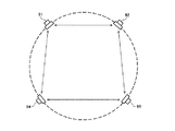
なお、上記の読み換えにより、仮想音源が図5の再生用スピーカと同様に直線上に並んでいる場合については説明できる。しかし、図12で受聴者と左右のスピーカと仮想音源との位置関係の他の例を示すように、仮想音源121a〜121eを、図9におけるスピーカ配置の円(図12中の破線で示す円)と同心円の円弧上に並べた場合についても、例えばその中心点に受聴者122を配置することによって、同様に仮想音源への信号割り当てが可能である。
In addition, the case where the virtual sound source is arranged on a straight line like the reproduction speaker of FIG. However, as shown in FIG. 12, another example of the positional relationship between the listener, the left and right speakers, and the virtual sound source, the
以上、上記着目ペア判定処理で図10における左フロントスピーカ91と右フロントスピーカ92のペアに着目した場合について、説明してきた。この仮想音源割り当てにより、左フロントスピーカ91と右フロントスピーカ92の音声信号のk番目の線スペクトルについては図5の再生用スピーカ52a〜52eと同様に直線上に並んでいる仮想音源、あるいは、図12の仮想音源121a〜121eに割り当てられたが、図10における左サラウンドスピーカ94と右サラウンドスピーカ95の音声信号それぞれのk番目の線スペクトルについては、まだ割り当てが行われていない。
In the above, the case where attention is paid to the pair of the
それらの割り当てについて図13を参照して説明する。図13は、受聴者と左右のスピーカ及び左右のサラウンドスピーカと仮想音源との位置関係の例を説明するための模式図である。それらの割り当ては、図13に示すように、左サラウンドスピーカ94の音声信号のk番目の線スペクトルは、受聴者132から見たときの左サラウンドスピーカ94と同じ方向の仮想音源131aに割り当てる。同様に、右サラウンドスピーカ95の音声信号のk番目の線スペクトルは、受聴者132から見たときの右サラウンドスピーカ95と同じ方向の仮想音源131bに割り当てる。
These assignments will be described with reference to FIG. FIG. 13 is a schematic diagram for explaining an example of a positional relationship between a listener, left and right speakers, and left and right surround speakers and a virtual sound source. As shown in FIG. 13, the k-th line spectrum of the audio signal of the
以上のようにして、ステップS34における、k番目の線スペクトルについて、4つのチャネルの、仮想音源への割り当てが行われる。ここでは、着目ペア判定処理の結果、図10における左フロントスピーカ91と右フロントスピーカ92に着目して相関信号と無相関信号の分離処理を行ったが、着目ペア判定処理の結果、着目する対象が異なることもある。そのような場合について、図14〜図16を参照して説明する。図14〜図16は、受聴者と左右のスピーカ及び左右のサラウンドスピーカと仮想音源との位置関係の他の例を説明するための模式図である。
As described above, in step S34, four channels are assigned to the virtual sound source for the k-th line spectrum. Here, as a result of the target pair determination process, the correlation signal and the uncorrelated signal are separated by focusing on the
着目ペア判定処理の結果、例えば左フロントスピーカ91と左サラウンドスピーカ94に着目するという結果になった場合は、図14に示すように、左フロントスピーカ91と左サラウンドスピーカ94についてのk番目の線スペクトルの相関信号と無相関信号が仮想音源141a〜141eに割り当てられ、右フロントスピーカ92のk番目の線スペクトルが仮想音源141fに、右サラウンドスピーカ95のk番目の線スペクトルが仮想音源141gに、それぞれ割り当てられる。
As a result of the focused pair determination process, for example, when the result is that the
着目するペアが他のペアとなった場合にも同様である。左サラウンドスピーカ94と右サラウンドスピーカ95に着目するという結果になった場合、図15に示すように、左サラウンドスピーカ94と右サラウンドスピーカ95についてのk番目の線スペクトルの相関信号と無相関信号が仮想音源151a〜151eに割り当てられ、左フロントスピーカ91のk番目の線スペクトルが仮想音源151fに、右サラウンドスピーカ95のk番目の線スペクトルが仮想音源151gに、それぞれ割り当てられる。また、右サラウンドスピーカ95と右フロントスピーカ92に着目するという結果になった場合、図16に示すように、右サラウンドスピーカ95と右フロントスピーカ92についてのk番目の線スペクトルの相関信号と無相関信号が仮想音源161a〜161eに割り当てられ、左サラウンドスピーカ94のk番目の線スペクトルが仮想音源151fに、左フロントスピーカ91のk番目の線スペクトルが仮想音源151gに、それぞれ割り当てられる。
The same applies when the pair of interest is another pair. When the result of focusing attention on the
上述のような処理を、ステップS31a,S31bのループにより全ての線スペクトルについて行う。例えば、256点の離散フーリエ変換を行った場合は1〜127番目の線スペクトルまで、512点の離散フーリエ変換を行った場合は1〜255番目の線スペクトルまで、セグメントの全点(1024点)について離散フーリエ変換を行った場合は1〜511番目の線スペクトルまで、となる。 The process as described above is performed for all line spectra by the loop of steps S31a and S31b. For example, when 256 discrete Fourier transforms are performed, all the points of the segment (1024 points) up to the 1st to 127th line spectrum, and when 512 discrete Fourier transforms are performed, the 1st to 255th line spectrum. When the discrete Fourier transform is performed for, the first to 511th line spectra are obtained.
その結果、図17に示すような仮想音源171の数をJ(この例ではJ=16)とすると、各仮想音源(出力チャネル)に対する周波数領域の出力音声信号Y1(k)、・・・、YJ(k)が求まる。これら出力が、図2における分離抽出部22の出力結果となる。
As a result, if the number of
ここで、図17は、左右のスピーカ及び左右のサラウンドスピーカと全ての仮想音源との位置関係の例を説明するための模式図で、図18は図17とは異なる例を説明するための模式図である。図17の例では、16個の仮想音源171を図9における各スピーカ91〜95を結ぶ円と同心円周上に配置したが、図18の例のように、16個の仮想音源181を四角形(この例では台形)上に並ぶように配置してもよい。図18の例は、4つの辺のそれぞれにおいて仮想音源181が直線上に並ぶような配置例であり、図5で説明すると再生用スピーカ52a〜52eの位置に配置した仮想音源を各辺毎に組み合わせたものである。
Here, FIG. 17 is a schematic diagram for explaining an example of the positional relationship between the left and right speakers and the left and right surround speakers and all virtual sound sources, and FIG. 18 is a schematic diagram for explaining an example different from FIG. FIG. In the example of FIG. 17, 16
また、ここでは例として5.1chサラウンドシステムの信号の変換処理について説明したが、6.1chや7.1chサラウンドシステムでも、同様に変換処理が可能である。この点について図19及び図20を参照して説明する。図19は、6.1chサラウンドシステムのスピーカ群において、LFEを除いた6つのスピーカのうち、ダウンミックス後の出力対象スピーカの配置例を示す図である。図20は、7.1chサラウンドシステムのスピーカ群において、LFEを除いた7つのスピーカのうち、ダウンミックス後の出力対象スピーカの配置例を示す図である。 Further, here, the conversion processing of the signal of the 5.1ch surround system has been described as an example, but the conversion processing can be similarly performed in the 6.1ch or 7.1ch surround system. This point will be described with reference to FIGS. FIG. 19 is a diagram illustrating an arrangement example of output target speakers after downmixing among the six speakers excluding LFE in the speaker group of the 6.1ch surround system. FIG. 20 is a diagram illustrating an arrangement example of output target speakers after downmixing among seven speakers excluding LFE in the speaker group of the 7.1ch surround system.
6.1chシステムにおいても、センター(C)チャネルをLチャネルとRチャネルにダウンミックスし、L/R/L S /R S /CBの5chのうち、図19において矢印で示すような各チャネルのペアを考慮して、前述と同様の処理を行えばよい。7.1chシステムにおいても、センター(C)チャネルをLチャネルとRチャネルにダウンミックスし、L/R/L S /R S /LB/RBの6chのうち、図20において矢印で示すような各チャネルのペアを考慮して、前述と同様の処理を行えばよい。 Also in the 6.1ch system, the center (C) channel is downmixed into the L channel and the R channel, and each of the 5 channels of L / R / L S / R S / C B as indicated by the arrows in FIG. In consideration of this pair, the same processing as described above may be performed. Also in 7.1ch system, downmixed center (C) channels L and R channels, among the L / R / L S / R S / L B / of R B 6ch, as indicated by arrows in FIG. 20 In consideration of each channel pair, the same processing as described above may be performed.
このように、入力音声信号は、5.1chあるいは6.1chあるいは7.1chサラウンド音響信号であり、ダウンミックスする1つのチャネルは前方中央のチャネルの入力音声信号であることが好ましい。これは、前方中央のチャネルは上述したように左右のフロントチャネルとの間で音圧パニングを行っているが、そのような場合でも本例では適切な音像が得られるためである。なお、サブウーファーの音声信号は通常、別に処理されるため、入力音声信号はそれらのいずれかのサラウンド音響信号からサブウーファーのチャネルを除いた音響信号と捉えることもできる。そして、このようなサラウンド音声信号を、センターチャネルをダウンミックスした上で、線スペクトル毎または小帯域毎に、隣合うチャネルのペアのうち、着目するペアを判定し、着目するペアについてのみ相関信号/無相関信号分離を行うことにより、左右のフロントチャネルとの間で音圧パニングを行っていたとしても、サラウンド音響信号を、波面合成再生方式で適切な音像として再生することができる。また、これらのサラウンド音響信号に限らず、9.1chなどのサラウンド音響信号を入力音声信号として適用することもできる。 Thus, it is preferable that the input audio signal is a 5.1ch, 6.1ch, or 7.1ch surround sound signal, and one channel to be downmixed is the input audio signal of the front center channel. This is because sound pressure panning is performed between the front center channel and the left and right front channels as described above, but an appropriate sound image can be obtained in this example even in such a case. Since the subwoofer audio signal is usually processed separately, the input audio signal can be regarded as an acoustic signal obtained by removing the subwoofer channel from any of the surround sound signals. Then, after down-mixing the center channel of such a surround sound signal, the pair of interest is determined from the adjacent channel pairs for each line spectrum or for each small band, and the correlation signal is obtained only for the pair of interest. By performing the uncorrelated signal separation, even if sound pressure panning is performed between the left and right front channels, the surround sound signal can be reproduced as an appropriate sound image by the wavefront synthesis reproduction method. Further, not only these surround sound signals but also a surround sound signal such as 9.1ch can be applied as an input sound signal.
以上のようにして本例における分離抽出部22の処理がなされる。
次に、逆変換部23の処理がなされる。逆変換部23は、分離抽出部22で抽出された上記着目した組み合わせについての相関信号(またはその相関信号及び無相関信号)に対して、もしくはその相関信号から生成された音声信号に対して、もしくはその相関信号及びその無相関信号から生成された音声信号に対して、離散フーリエ逆変換を施す。また、逆変換部23は、上記着目した組み合わせ以外のチャネルについて変換部21で変換された音声信号に対しても、離散フーリエ逆変換を施す。
As described above, the processing of the separation and
Next, processing of the
具体的には、逆変換部23では、分離抽出部22から出力された各出力チャネルを離散フーリエ逆変換することによって、上述した数式(35)により時間領域の出力音声信号y′J(m)を求める。なお、ここでは、上記着目した組み合わせについての相関信号及び無相関信号に対して離散フーリエ逆変換を施すとともに、上記着目した組み合わせ以外のチャネルについて変換部21で変換された音声信号に対して離散フーリエ逆変換を施す例を挙げているが、他の場合も同様である。
Specifically, the
数式(35)に関し、数式(36)、(37)で説明したように、本例においても離散フーリエ変換した信号は、窓関数乗算後の信号であったため、逆変換して得られた信号y′J(m)も窓関数が乗算された状態になっている。したがって、そうして得られた信号に、数式(2)に示す窓関数を再度乗算し、1つ前に処理したセグメントの先頭から1/4セグメント長ずつずらしながら出力バッファに加算していくことにより変換後のデータを得る。 As described in equations (36) and (37) with respect to equation (35), the signal obtained by inverse transformation is also obtained in this example because the signal subjected to the discrete Fourier transform is a signal after window function multiplication. ′ J (m) is also multiplied by the window function. Therefore, the signal obtained in this way is multiplied by the window function shown in Equation (2) again, and added to the output buffer while shifting by 1/4 segment length from the head of the previous processed segment. To obtain the converted data.
次に、図21〜図24を参照して各スピーカに対する音声信号の生成について説明する。図21は、非特許文献1に記載の技術において、1つの直線上に並べたスピーカ群の背後に仮想音源を設けた場合に、各仮想音源に対応する音を出力するスピーカについて説明するための模式図である。図22〜図24は、図1の音声信号再生装置におけるスピーカ群の配置例を説明するための模式図である。
Next, generation of audio signals for each speaker will be described with reference to FIGS. FIG. 21 illustrates a speaker that outputs sound corresponding to each virtual sound source when a virtual sound source is provided behind a group of speakers arranged on one straight line in the technique described in
本例における音声出力信号生成部24では、逆変換部23で生成した各仮想音源の音声信号を、上述の非特許文献1に記載の技術に則って、各スピーカに対する音声信号を生成する。ただし、非特許文献1に記載の技術では、図21に示すように、1つの直線上に並べたスピーカ群(スピーカアレイ)211の背後に仮想音源212a〜212eがある場合に、「どのスピーカが、どの仮想音源に対応する音を出力するか」を判定するために、仮想音源(仮想音源212bについて図示)からスピーカアレイ211の配列方向を示す直線に下ろした垂線と、仮想音源212bとスピーカを結んだ線とがなす角度ψが、ある一定値より小さい場合に、そのスピーカはその仮想音源212bの音を出力する、という方法が採用されている。
In the audio output
しかし、図12〜図16で適用した仮想音源の配置例や図17や図18で説明した仮想音源の配置例では、少なくとも一部で一直線上に並ばないように配列させたスピーカ群が必要であり、例えば図22で例示するような各仮想音源222と各スピーカ221の配置が必要となる。そのため、非特許文献1に記載の方法では、ある仮想音源(例えば仮想音源222a)の音が、それと対面するスピーカ群221bからも出力されてしまい、音像定位に悪影響を及ぼす。
However, the virtual sound source arrangement example applied in FIGS. 12 to 16 and the virtual sound source arrangement example described with reference to FIGS. 17 and 18 require speaker groups arranged so that at least a part thereof is not aligned. Yes, for example, the arrangement of each
したがって、例えば図22の仮想音源222aの音を、スピーカ群221のうちどのスピーカが出力するかどうかの判定には、各仮想音源222を配置した円の中心点224と仮想音源222aとを結んだ直線と、判定するスピーカ(例えば図22のスピーカ221a)と中心点224とを結んだ直線とがなす角度ψaが、ある一定値より小さい場合に、スピーカ221aは、仮想音源222aの音を出力すると判定する。これを全てのスピーカと全ての仮想音源の組み合わせに対して行うことによって、図22のような配置をする場合でも各スピーカの出力する音声信号を決定することが可能となる。
Therefore, for example, to determine which speaker of the
このようにして、音声信号処理部13は、マルチチャネル再生方式の5つ以上のチャネルの入力音声信号を、仮想的に存在する音源である仮想音源に対する音像としてスピーカ群により再生させるために変換することができる。ここで、図22で例示し後述の図23、図24で例示するように、本例におけるスピーカ群は、少なくとも一部で一直線上に並ばないように配列されており、仮想音源とスピーカそれぞれと中心点とを結んだ直線がなす角度によって、出力対象とするスピーカを決定する。
In this way, the audio
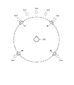
また、図23で例示するように、スピーカ群231を円周上に並べた場合についても、同じ方法を用いることによって、各仮想音源232に対する音声信号を決定することが可能となる。
Further, as exemplified in FIG. 23, even when the
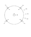
また、例えば図10における左サラウンドスピーカ94と右サラウンドスピーカ95のペアには着目しないという制約をつけた上で、前述の処理を行うと、音声信号が割り当てられる仮想音源は、図24に示すような仮想音源242(この例では13個の仮想音源242)に限定され、それらの仮想音源242を、全周囲ではなく図24に示すように三方のみを囲う配置のスピーカ群241で出力することも可能である。
Further, for example, when the above processing is performed with the restriction that the pair of the
以上、説明したように、本例における音声信号処理部13でなした処理は、着目ペアについてのみ相関信号・無相関信号に分離した上で仮想音源(または実在のスピーカ)への割り当てを行う処理であり、この処理は、同じ線スペクトルあるいは小帯域に属する音像は1つであるといった仮定を置くことを意味している。そして、その仮定では正確な音像位置を再現するための変換処理が可能となる。よって、このような変換処理により、マルチチャネル再生方式の5つ以上のチャネルの入力音声信号を、スピーカ群を用いて再生する際に適切な音像を提供できる音声信号に変換することができる。
As described above, the processing performed by the audio
特に、本発明では着目ペアの判定を、電力の大きさを用いて、もしくは電力の大きさ及び相関係数(つまり相関係数の大きさ)を用いて行っている。そのため、ダウンミックス元のチャネルの信号(この例ではC信号)に含まれる周波数成分については、ダウンミックス先のペアの電力が他のペアの電力に比べて大きくなり、ダウンミックス先のペアが着目ペアに決定される。したがって、センターチャネル信号と左フロントチャネル信号との間、あるいは、センターチャネル信号と右フロントチャネル信号との間で、音圧パニングを行っている場合にも、適切な音像に変換することができる。無論、他の周波数成分(この例では、C信号に含まれない周波数成分であって、元のL、R、LS、RSの信号に含まれる周波数成分)については、他のペアが選択された結果、同様に適切な音像に変換することができる。 In particular, in the present invention, the pair of interest is determined using the power magnitude, or using the power magnitude and the correlation coefficient (that is, the correlation coefficient magnitude). Therefore, for the frequency component included in the downmix source channel signal (C signal in this example), the power of the downmix destination pair becomes larger than the power of the other pair, and the downmix destination pair is focused. Determined to be a pair. Therefore, even when sound pressure panning is performed between the center channel signal and the left front channel signal, or between the center channel signal and the right front channel signal, the sound image can be converted into an appropriate sound image. Of course, for other frequency components (in this example, frequency components that are not included in the C signal and are included in the original L, R, L S , and R S signals), other pairs are selected. As a result, the sound image can be similarly converted into an appropriate sound image.
次に、本発明の実装について簡単に説明する。本発明は、例えばホームシアターシステムやミニシアターシステムなど、映像の伴う装置に利用できる。図25は、図1の音声信号再生装置を備えた映像表示システムの構成例を示す図である。図25で示す部屋250のように、本発明に係る音声信号再生装置は、部屋の壁の三方(あるいは四方)にスピーカ群251〜253を並べて取り付けたスピーカシステムに適用することができる。そして、図25で例示するように、テレビ装置等の映像表示装置254にこのスピーカシステムを接続し、映像表示装置254で表示させた映像に対応する音声をスピーカ群251〜253から出力することもできる。
Next, the implementation of the present invention will be briefly described. The present invention can be used for an apparatus with an image such as a home theater system or a mini theater system. FIG. 25 is a diagram illustrating a configuration example of a video display system including the audio signal reproduction device of FIG. As in a
さらに、本例においても、線スペクトル毎(または小帯域毎)に図4で例示したθや数式(14)のPS (k)が得られる。よって、本例においても、スピーカ群251〜253の各スピーカの傍にLED255〜257を配置したように三方や四方(あるいは円形状)に配置したアレイスピーカに複数の発光部を設けておけば、図8で説明したように音の強さに応じて発光色を変化させたり発光強度を変化させたりすることが、三方や四方(あるいは円形状)で可能となる。また、受聴者の前方のみ、LED256の代わりにあるいはLED256に加えて、図7で例示した棒グラフ72を映像表示装置254に表示させることもできる。
Furthermore, also in this example, θ illustrated in FIG. 4 and P S (k) of Expression (14 ) are obtained for each line spectrum (or for each small band). Therefore, also in this example, if a plurality of light emitting units are provided in an array speaker arranged in three or four directions (or circular shape) such that
なお、上述した各例において適用可能な波面合成再生方式としては、上述したようにスピーカアレイ(複数のスピーカ)を備えて仮想音源に対する音像としてそれらのスピーカから出力するようにする方式であればよく、非特許文献1に記載のWFS方式の他、人間の音像知覚に関する現象としての先行音効果(ハース効果)を利用した方式など様々な方式が挙げられる。ここで、先行音効果とは、同一の音声を複数の音源から再生し、音源それぞれから聴取者に到達する各音声に小さな時間差がある場合、先行して到達した音声の音源方向に音像が定位する効果を指し示したものである。この効果を利用すれば、仮想音源位置に音像を知覚させることが可能となる。ただし、その効果だけで音像を明確に知覚させることは難しい。ここで、人間は音圧を最も高く感じる方向に音像を知覚するという性質も持ち合わせている。したがって、音声信号再生装置において、上述の先行音効果と、この最大音圧方向知覚の効果とを組み合わせ、これにより、少ない数のスピーカでも仮想音源の方向に音像を知覚させることが可能になる。
As the wavefront synthesis reproduction method applicable in each of the above-described examples, any method may be used as long as it includes a speaker array (a plurality of speakers) and outputs sound images from virtual speakers as described above. In addition to the WFS method described in
以上、本発明に係る音声信号再生装置の様々な例について、入力音声信号がマルチチャネル再生方式であることを前提に説明した。入力音声信号が波面合成再生方式の音声信号である場合について補足的に説明する。この場合には、本発明の主たる特徴である音像表示処理のように相関信号の分離等の処理を行わずとも、入力音声信号が示す音源位置の情報に合う位置にその信号電力値(または音圧レベル)を示す情報を表示し、かつ例えば波面合成再生方式でスピーカアレイから音声出力すればよい。これにより、入力音声信号が波面合成再生方式の音声信号である場合においても、聴覚と知覚とで音像位置が一致するように音像位置を表示させることは可能である。 As described above, various examples of the audio signal reproduction device according to the present invention have been described on the assumption that the input audio signal is a multi-channel reproduction system. A supplemental description will be given of a case where the input audio signal is a wavefront synthesis reproduction type audio signal. In this case, the signal power value (or sound level) is adjusted to a position that matches the sound source position information indicated by the input sound signal without performing processing such as separation of the correlation signal as in the sound image display processing that is the main feature of the present invention. (Pressure level) may be displayed, and sound may be output from the speaker array by, for example, a wavefront synthesis reproduction method. Thereby, even when the input sound signal is a sound signal of the wavefront synthesis reproduction method, it is possible to display the sound image position so that the sound image position matches between hearing and perception.
また、例えば図1で例示した音声信号処理部13や表示制御部18における各構成要素など、本発明に係る音声信号再生装置の各構成要素は、例えばマイクロプロセッサ(またはDSP:Digital Signal Processor)、メモリ、バス、インターフェイス、周辺装置などのハードウェアと、これらのハードウェア上にて実行可能なソフトウェアとにより実現できる。表示部19を除き、上記ハードウェアの一部または全部は集積回路/IC(Integrated Circuit)チップセットとして搭載することができ、その場合、上記ソフトウェアは上記メモリに記憶しておければよい。また、本発明の各構成要素の全てをハードウェアで構成してもよく、その場合についても同様に、そのハードウェアの一部または全部を集積回路/ICチップセットとして搭載することも可能である。
In addition, each component of the audio signal reproduction device according to the present invention such as each component in the audio
また、上述した様々な構成例における機能を実現するためのソフトウェアのプログラムコードを記録した記録媒体を、音声信号再生装置となる汎用コンピュータ等の装置に供給し、その装置内のマイクロプロセッサまたはDSPによりプログラムコードが実行されることによっても、本発明の目的が達成される。この場合、ソフトウェアのプログラムコード自体が上述した様々な構成例の機能を実現することになり、このプログラムコード自体や、プログラムコードを記録した記録媒体(外部記録媒体や内部記憶装置)であっても、そのコードを制御側が読み出して実行することで、本発明を構成することができる。外部記録媒体としては、例えばCD−ROMまたはDVD−ROMなどの光ディスクやメモリカード等の不揮発性の半導体メモリなど、様々なものが挙げられる。内部記憶装置としては、ハードディスクや半導体メモリなど様々なものが挙げられる。また、プログラムコードはインターネットからダウンロードして実行することや、放送波から受信して実行することもできる。 In addition, a recording medium on which a program code of software for realizing the functions in the various configuration examples described above is recorded is supplied to a device such as a general-purpose computer serving as an audio signal reproduction device, and is then processed by a microprocessor or DSP in the device. The object of the present invention is also achieved by executing the program code. In this case, the software program code itself realizes the functions of the above-described various configuration examples. Even if the program code itself or a recording medium (external recording medium or internal storage device) on which the program code is recorded is used. The present invention can be configured by the control side reading and executing the code. Examples of the external recording medium include various media such as an optical disk such as a CD-ROM or a DVD-ROM and a non-volatile semiconductor memory such as a memory card. Examples of the internal storage device include various devices such as a hard disk and a semiconductor memory. The program code can be downloaded from the Internet and executed, or received from a broadcast wave and executed.
以上、本発明に係る音声信号再生装置について説明したが、処理の流れをフロー図で例示したように、本発明は、音声信号を再生する音声信号再生方法としての形態も採り得る。この音声信号再生方法は、次の分離ステップ、算出ステップ、加算ステップ、及び音像表示ステップを含む。 The audio signal reproduction apparatus according to the present invention has been described above. However, as illustrated in the flowchart of the processing flow, the present invention can also take the form of an audio signal reproduction method for reproducing an audio signal. This audio signal reproduction method includes the following separation step, calculation step, addition step, and sound image display step.
分離ステップは、分離部が、2つの音声信号を、周波数毎または周波数帯域毎に周波数についての相関信号と無相関信号とに分離するステップである。算出ステップは、算出部が、分離ステップで分離された各相関信号について、音像方向及び信号電力値を算出するステップである。加算ステップは、加算部が、各相関信号について、音像方向に基づき、予め定められた複数の音像方向グループのうちの1つに信号電力値を割り当て、音像方向グループ毎に信号電力値の加算値を求めるステップである。音像表示ステップは、音像表示部が、複数の音像方向グループのそれぞれに対応する位置に各音像方向グループについての加算値を示す情報を表示するステップである。その他の応用例については、音声信号再生装置について説明した通りであり、その説明を省略する。 The separation step is a step in which the separation unit separates the two audio signals into a correlation signal and a non-correlation signal for each frequency or frequency band. The calculation step is a step in which the calculation unit calculates a sound image direction and a signal power value for each correlation signal separated in the separation step. In the adding step, for each correlation signal, the adding unit assigns a signal power value to one of a plurality of predetermined sound image direction groups based on the sound image direction, and adds the signal power value for each sound image direction group. This is a step for obtaining. The sound image display step is a step in which the sound image display unit displays information indicating an addition value for each sound image direction group at a position corresponding to each of the plurality of sound image direction groups. Other application examples are the same as those described for the audio signal reproducing apparatus, and the description thereof is omitted.
なお、上記プログラムコード自体は、換言すると、この音声信号再生方法をコンピュータに実行させるためのプログラムである。すなわち、このプログラムは、コンピュータに、2つの音声信号を、周波数毎または周波数帯域毎に周波数についての相関信号と無相関信号とに分離する分離ステップと、分離ステップで分離された各相関信号について、音像方向及び信号電力値を算出する算出ステップと、各相関信号について、音像方向に基づき、予め定められた複数の音像方向グループのうちの1つに信号電力値を割り当て、音像方向グループ毎に信号電力値の加算値を求める加算ステップと、複数の音像方向グループのそれぞれに対応する位置に各音像方向グループについての加算値を示す情報を表示する音像表示ステップと、を実行させるためのプログラムである。その他の応用例については、音声信号再生装置について説明した通りであり、その説明を省略する。 In other words, the program code itself is a program for causing a computer to execute the audio signal reproduction method. That is, this program causes a computer to separate two audio signals into a correlation signal and a non-correlation signal for each frequency or frequency band, and for each correlation signal separated in the separation step, A calculation step for calculating a sound image direction and a signal power value, and for each correlation signal, a signal power value is assigned to one of a plurality of predetermined sound image direction groups based on the sound image direction, and a signal is generated for each sound image direction group. This is a program for executing an addition step for obtaining an addition value of power values, and a sound image display step for displaying information indicating the addition value for each sound image direction group at a position corresponding to each of the plurality of sound image direction groups. . Other application examples are the same as those described for the audio signal reproducing apparatus, and the description thereof is omitted.
以上説明したように、本発明に係る音声信号再生装置は、2つの音声信号を、周波数毎または周波数帯域毎に周波数についての相関信号と無相関信号とに分離する分離部と、該分離部で分離された各相関信号について、音像方向及び信号電力値を算出する算出部と、各相関信号について、前記音像方向に基づき、予め定められた複数の音像方向グループのうちの1つに前記信号電力値を割り当て、該音像方向グループ毎に前記信号電力値の加算値を求める加算部と、前記複数の音像方向グループのそれぞれに対応する位置に各音像方向グループについての前記加算値を示す情報を表示する音像表示部と、を備えたことを特徴としたものである。これにより、聴覚と知覚とで音像位置が一致するように音像位置を表示させることができ、受聴者の没入感を高めることができる。 As described above, the audio signal reproduction device according to the present invention separates two audio signals into a correlated signal and a non-correlated signal for each frequency or frequency band, and the separating unit. A calculation unit for calculating a sound image direction and a signal power value for each separated correlation signal, and the signal power for one of a plurality of predetermined sound image direction groups based on the sound image direction for each correlation signal. An adder for assigning a value and obtaining an added value of the signal power value for each sound image direction group, and displaying information indicating the added value for each sound image direction group at a position corresponding to each of the plurality of sound image direction groups And a sound image display unit. As a result, the sound image position can be displayed so that the sound image position matches between hearing and perception, and the listener's immersive feeling can be enhanced.
前記音像表示部は、棒グラフ形式で、前記複数の音像方向グループのそれぞれに対応する位置に各音像方向グループについての前記加算値を示す情報を表示するようにしてもよい。これにより、受聴者の没入感をより増すことができる。 The sound image display unit may display information indicating the added value for each sound image direction group at a position corresponding to each of the plurality of sound image direction groups in a bar graph format. Thereby, a listener's immersion feeling can be increased more.
もしくは、前記音像表示部は、複数の発光部を有し、前記複数の音像方向グループのそれぞれに対応する位置の前記発光部の発光色を、各音像方向グループについての前記加算値を示す情報に応じて変化させるようにしてもよい。音の強さに応じて発光色を変化させることで、例えば音楽ビデオを再生している場合や音楽を再生している場合に、ライブ会場での感覚を受聴者に与えることができる。 Alternatively, the sound image display unit includes a plurality of light emitting units, and the light emission color of the light emitting unit at a position corresponding to each of the plurality of sound image direction groups is used as information indicating the added value for each sound image direction group. You may make it change according to it. By changing the emission color according to the intensity of the sound, for example, when playing music video or playing music, it is possible to give the listener the feeling at the live venue.
もしくは、前記音像表示部は、複数の発光部を有し、前記複数の音像方向グループのそれぞれに対応する位置の前記発光部の発光強度を、各音像方向グループについての前記加算値を示す情報に応じて変化させるようにしてもよい。音の強さに応じて発光強度を変化させることで、例えば音楽ビデオを再生している場合や音楽を再生している場合に、ライブ会場での感覚を受聴者に与えることができる。 Alternatively, the sound image display unit includes a plurality of light emitting units, and the light emission intensity of the light emitting unit at a position corresponding to each of the plurality of sound image direction groups is used as information indicating the added value for each sound image direction group. You may make it change according to it. By changing the light emission intensity in accordance with the intensity of the sound, for example, when playing music video or playing music, it is possible to give the listener the feeling at the live venue.
本発明に係る音声信号再生方法は、分離部が、2つの音声信号を、周波数毎または周波数帯域毎に周波数についての相関信号と無相関信号とに分離する分離ステップと、算出部が、前記分離ステップで分離された各相関信号について、音像方向及び信号電力値を算出する算出ステップと、加算部が、各相関信号について、前記音像方向に基づき、予め定められた複数の音像方向グループのうちの1つに前記信号電力値を割り当て、該音像方向グループ毎に前記信号電力値の加算値を求める加算ステップと、音像表示部が、前記複数の音像方向グループのそれぞれに対応する位置に各音像方向グループについての前記加算値を示す情報を表示する音像表示ステップと、を含むことを特徴としたものである。これにより、聴覚と知覚とで音像位置が一致するように音像位置を表示させることができ、受聴者の没入感を高めることができる。 In the audio signal reproduction method according to the present invention, the separation unit separates the two audio signals into a correlation signal and a non-correlation signal for each frequency or frequency band, and a calculation unit includes the separation A calculation step for calculating a sound image direction and a signal power value for each correlation signal separated in the step, and an adding unit, for each correlation signal, of a plurality of predetermined sound image direction groups based on the sound image direction An addition step of assigning the signal power value to one and obtaining an addition value of the signal power value for each sound image direction group, and a sound image display unit at each sound image direction at a position corresponding to each of the plurality of sound image direction groups And a sound image display step for displaying information indicating the added value for the group. As a result, the sound image position can be displayed so that the sound image position matches between hearing and perception, and the listener's immersive feeling can be enhanced.
本発明に係るプログラムは、コンピュータに、2つの音声信号を、周波数毎または周波数帯域毎に周波数についての相関信号と無相関信号とに分離する分離ステップと、前記分離ステップで分離された各相関信号について、音像方向及び信号電力値を算出する算出ステップと、各相関信号について、前記音像方向に基づき、予め定められた複数の音像方向グループのうちの1つに前記信号電力値を割り当て、該音像方向グループ毎に前記信号電力値の加算値を求める加算ステップと、前記複数の音像方向グループのそれぞれに対応する位置に各音像方向グループについての前記加算値を示す情報を表示する音像表示ステップと、を実行させるためのプログラムである。これにより、本発明の機能をプログラムとして提供することができる。 A program according to the present invention includes a separation step of separating two audio signals into a correlation signal and a non-correlation signal for each frequency or frequency band, and each correlation signal separated in the separation step. Calculating a sound image direction and a signal power value, and assigning the signal power value to one of a plurality of predetermined sound image direction groups based on the sound image direction for each correlation signal, An addition step for obtaining an addition value of the signal power values for each direction group; and a sound image display step for displaying information indicating the addition value for each sound image direction group at a position corresponding to each of the plurality of sound image direction groups; Is a program for executing Thereby, the function of the present invention can be provided as a program.
本発明に係る記録媒体は、上記のプログラムを記録したコンピュータ読み取り可能な記録媒体である。これにより、上記プログラムを記録媒体で流通させることができる。 A recording medium according to the present invention is a computer-readable recording medium on which the above program is recorded. Thus, the program can be distributed on the recording medium.
10…音声信号再生装置、11…デコーダ、12…音声信号抽出部、13…音声信号処理部、14…D/Aコンバータ、15…増幅器、16,16a,16b,16c…スピーカ、17…スピーカアレイ、18…表示制御部、18a…加算部、19…表示部、21…変換部、22…分離抽出部、22a…分離部、22b…算出部、23…逆変換部、24…音声出力信号生成部、70…テレビ装置、71…表示パネル、72…棒グラフ、73a,73b,73c,…情報、81a,81b,81c…LED。 DESCRIPTION OF SYMBOLS 10 ... Audio | voice signal reproduction apparatus, 11 ... Decoder, 12 ... Audio signal extraction part, 13 ... Audio signal processing part, 14 ... D / A converter, 15 ... Amplifier, 16, 16a, 16b, 16c ... Speaker, 17 ... Speaker array , 18 ... display control unit, 18a ... addition unit, 19 ... display unit, 21 ... conversion unit, 22 ... separation / extraction unit, 22a ... separation unit, 22b ... calculation unit, 23 ... inverse conversion unit, 24 ... audio output signal generation , 70 ... TV device, 71 ... Display panel, 72 ... Bar graph, 73a, 73b, 73c, ... Information, 81a, 81b, 81c ... LED.
Claims (5)
該分離部で分離された各相関信号について、音像方向及び信号電力値を算出する算出部と、
各相関信号について前記音像方向に基づき予め定められた複数の音像方向グループに割り当てられた前記信号電力値に応じて、前記複数の音像方向グループのそれぞれに対応する表示を行う音像表示部と、
を備えたことを特徴とする音声信号再生装置。 The two audio signals, and a separation unit for separating the No. phases SekiShin for each frequency or each frequency band,
For each correlation signal separated by the separation unit, a calculation unit for calculating a sound image direction and a signal power value;
Depending on the signal power values assigned to the previous SL plurality of sound directions groups defined Me based-out pre sound image direction about the respective correlation signal, performs a display corresponding to each of the plurality of sound image direction Group A sound image display section;
An audio signal reproducing apparatus comprising:
算出部が、前記分離ステップで分離された各相関信号について、音像方向及び信号電力値を算出する算出ステップと、
音像表示部が、各相関信号について前記音像方向に基づき予め定められた複数の音像方向グループに割り当てられた前記信号電力値に応じて、前記複数の音像方向グループのそれぞれに対応する表示を行う音像表示ステップと、
を含む事を特徴とする音声信号再生方法。 Separation section, the two audio signals, and a separation step of separating the correlation signal for each frequency or each frequency band,
A calculation unit that calculates a sound image direction and a signal power value for each correlation signal separated in the separation step ;
The sound-image display unit is performed, the display corresponding to each of the plurality of sound image direction groups corresponding to the signal power values assigned to the plurality of sound image direction Group predetermined based on the sound image direction for each correlation signal A sound image display step;
A method of reproducing an audio signal, comprising:
Priority Applications (1)
| Application Number | Priority Date | Filing Date | Title |
|---|---|---|---|
| JP2013119366A JP6161962B2 (en) | 2013-06-06 | 2013-06-06 | Audio signal reproduction apparatus and method |
Applications Claiming Priority (1)
| Application Number | Priority Date | Filing Date | Title |
|---|---|---|---|
| JP2013119366A JP6161962B2 (en) | 2013-06-06 | 2013-06-06 | Audio signal reproduction apparatus and method |
Publications (3)
| Publication Number | Publication Date |
|---|---|
| JP2014239269A JP2014239269A (en) | 2014-12-18 |
| JP2014239269A5 JP2014239269A5 (en) | 2016-07-28 |
| JP6161962B2 true JP6161962B2 (en) | 2017-07-12 |
Family
ID=52136132
Family Applications (1)
| Application Number | Title | Priority Date | Filing Date |
|---|---|---|---|
| JP2013119366A Expired - Fee Related JP6161962B2 (en) | 2013-06-06 | 2013-06-06 | Audio signal reproduction apparatus and method |
Country Status (1)
| Country | Link |
|---|---|
| JP (1) | JP6161962B2 (en) |
Families Citing this family (2)
| Publication number | Priority date | Publication date | Assignee | Title |
|---|---|---|---|---|
| US9924291B2 (en) * | 2016-02-16 | 2018-03-20 | Sony Corporation | Distributed wireless speaker system |
| TWI673645B (en) * | 2018-11-27 | 2019-10-01 | 技嘉科技股份有限公司 | Computer system, display apparatus, and display method of an on-screen-display interface |
Family Cites Families (8)
| Publication number | Priority date | Publication date | Assignee | Title |
|---|---|---|---|---|
| JPS60177600U (en) * | 1984-05-01 | 1985-11-26 | 日本フア−ムウエア株式会社 | Sound image display device |
| GB2319346B (en) * | 1996-11-13 | 2001-03-21 | Sony Uk Ltd | Analysis of audio signals |
| US6977653B1 (en) * | 2000-03-08 | 2005-12-20 | Tektronix, Inc. | Surround sound display |
| US20080253592A1 (en) * | 2007-04-13 | 2008-10-16 | Christopher Sanders | User interface for multi-channel sound panner |
| JP2011239036A (en) * | 2010-05-06 | 2011-11-24 | Sharp Corp | Audio signal converter, method, program, and recording medium |
| JP5690082B2 (en) * | 2010-05-18 | 2015-03-25 | シャープ株式会社 | Audio signal processing apparatus, method, program, and recording medium |
| JP4810621B1 (en) * | 2010-09-07 | 2011-11-09 | シャープ株式会社 | Audio signal conversion apparatus, method, program, and recording medium |
| JP5760442B2 (en) * | 2011-01-13 | 2015-08-12 | ヤマハ株式会社 | Localization analysis apparatus and sound processing apparatus |
-
2013
- 2013-06-06 JP JP2013119366A patent/JP6161962B2/en not_active Expired - Fee Related
Also Published As
| Publication number | Publication date |
|---|---|
| JP2014239269A (en) | 2014-12-18 |
Similar Documents
| Publication | Publication Date | Title |
|---|---|---|
| JP7254137B2 (en) | Method and Apparatus for Decoding Ambisonics Audio Soundfield Representation for Audio Playback Using 2D Setup | |
| KR101341523B1 (en) | Method to generate multi-channel audio signals from stereo signals | |
| TWI517028B (en) | Audio spatialization and environment simulation | |
| RU2613731C2 (en) | Device for providing audio and method of providing audio | |
| RU2568926C2 (en) | Device and method of extracting forward signal/ambient signal from downmixing signal and spatial parametric information | |
| KR101567461B1 (en) | Apparatus for generating multi-channel sound signal | |
| KR101532505B1 (en) | Apparatus and method for generating an output signal employing a decomposer | |
| JP6284480B2 (en) | Audio signal reproducing apparatus, method, program, and recording medium | |
| EP2484127B1 (en) | Method, computer program and apparatus for processing audio signals | |
| Lee | 2D to 3D ambience upmixing based on perceptual band allocation | |
| JP6660982B2 (en) | Audio signal rendering method and apparatus | |
| Lee | Sound Source and Loudspeaker Base Angle Dependency of the Phantom Image Elevation Effect | |
| JP4810621B1 (en) | Audio signal conversion apparatus, method, program, and recording medium | |
| JP6161962B2 (en) | Audio signal reproduction apparatus and method | |
| Nowak et al. | On the perception of apparent source width and listener envelopment in wave field synthesis | |
| JP2011199707A (en) | Audio data reproduction device, and audio data reproduction method | |
| Floros et al. | Spatial enhancement for immersive stereo audio applications | |
| JP2013055439A (en) | Sound signal conversion device, method and program and recording medium | |
| JP6017352B2 (en) | Audio signal conversion apparatus and method | |
| Power | Future spatial audio: subjective evaluation of 3D surround systems | |
| JP5743003B2 (en) | Wavefront synthesis signal conversion apparatus and wavefront synthesis signal conversion method | |
| WO2013176073A1 (en) | Audio signal conversion device, method, program, and recording medium | |
| KR102380232B1 (en) | Method and apparatus for 3D sound reproducing | |
| KR102547423B1 (en) | Audio signal processor, system and methods for distributing an ambient signal to a plurality of ambient signal channels | |
| JP2015065551A (en) | Voice reproduction system |
Legal Events
| Date | Code | Title | Description |
|---|---|---|---|
| RD02 | Notification of acceptance of power of attorney |
Free format text: JAPANESE INTERMEDIATE CODE: A7422 Effective date: 20150909 |
|
| RD04 | Notification of resignation of power of attorney |
Free format text: JAPANESE INTERMEDIATE CODE: A7424 Effective date: 20150911 |
|
| RD04 | Notification of resignation of power of attorney |
Free format text: JAPANESE INTERMEDIATE CODE: A7424 Effective date: 20150915 |
|
| RD04 | Notification of resignation of power of attorney |
Free format text: JAPANESE INTERMEDIATE CODE: A7424 Effective date: 20150915 |
|
| A521 | Request for written amendment filed |
Free format text: JAPANESE INTERMEDIATE CODE: A523 Effective date: 20160606 |
|
| A621 | Written request for application examination |
Free format text: JAPANESE INTERMEDIATE CODE: A621 Effective date: 20160606 |
|
| A977 | Report on retrieval |
Free format text: JAPANESE INTERMEDIATE CODE: A971007 Effective date: 20170510 |
|
| TRDD | Decision of grant or rejection written | ||
| A01 | Written decision to grant a patent or to grant a registration (utility model) |
Free format text: JAPANESE INTERMEDIATE CODE: A01 Effective date: 20170516 |
|
| A61 | First payment of annual fees (during grant procedure) |
Free format text: JAPANESE INTERMEDIATE CODE: A61 Effective date: 20170614 |
|
| R150 | Certificate of patent or registration of utility model |
Ref document number: 6161962 Country of ref document: JP Free format text: JAPANESE INTERMEDIATE CODE: R150 |
|
| LAPS | Cancellation because of no payment of annual fees |