JP6161869B2 - Liquid ejector - Google Patents
Liquid ejector Download PDFInfo
- Publication number
- JP6161869B2 JP6161869B2 JP2012047697A JP2012047697A JP6161869B2 JP 6161869 B2 JP6161869 B2 JP 6161869B2 JP 2012047697 A JP2012047697 A JP 2012047697A JP 2012047697 A JP2012047697 A JP 2012047697A JP 6161869 B2 JP6161869 B2 JP 6161869B2
- Authority
- JP
- Japan
- Prior art keywords
- ink
- liquid
- liquid ejecting
- carriage
- tube
- Prior art date
- Legal status (The legal status is an assumption and is not a legal conclusion. Google has not performed a legal analysis and makes no representation as to the accuracy of the status listed.)
- Active
Links
Images


Classifications
-
- B—PERFORMING OPERATIONS; TRANSPORTING
- B41—PRINTING; LINING MACHINES; TYPEWRITERS; STAMPS
- B41J—TYPEWRITERS; SELECTIVE PRINTING MECHANISMS, i.e. MECHANISMS PRINTING OTHERWISE THAN FROM A FORME; CORRECTION OF TYPOGRAPHICAL ERRORS
- B41J25/00—Actions or mechanisms not otherwise provided for
- B41J25/001—Mechanisms for bodily moving print heads or carriages parallel to the paper surface
-
- B—PERFORMING OPERATIONS; TRANSPORTING
- B41—PRINTING; LINING MACHINES; TYPEWRITERS; STAMPS
- B41J—TYPEWRITERS; SELECTIVE PRINTING MECHANISMS, i.e. MECHANISMS PRINTING OTHERWISE THAN FROM A FORME; CORRECTION OF TYPOGRAPHICAL ERRORS
- B41J2/00—Typewriters or selective printing mechanisms characterised by the printing or marking process for which they are designed
- B41J2/005—Typewriters or selective printing mechanisms characterised by the printing or marking process for which they are designed characterised by bringing liquid or particles selectively into contact with a printing material
- B41J2/01—Ink jet
- B41J2/17—Ink jet characterised by ink handling
- B41J2/175—Ink supply systems ; Circuit parts therefor
-
- B—PERFORMING OPERATIONS; TRANSPORTING
- B41—PRINTING; LINING MACHINES; TYPEWRITERS; STAMPS
- B41J—TYPEWRITERS; SELECTIVE PRINTING MECHANISMS, i.e. MECHANISMS PRINTING OTHERWISE THAN FROM A FORME; CORRECTION OF TYPOGRAPHICAL ERRORS
- B41J2/00—Typewriters or selective printing mechanisms characterised by the printing or marking process for which they are designed
- B41J2/005—Typewriters or selective printing mechanisms characterised by the printing or marking process for which they are designed characterised by bringing liquid or particles selectively into contact with a printing material
- B41J2/01—Ink jet
- B41J2/17—Ink jet characterised by ink handling
- B41J2/175—Ink supply systems ; Circuit parts therefor
- B41J2/17503—Ink cartridges
- B41J2/17506—Refilling of the cartridge
- B41J2/17509—Whilst mounted in the printer
-
- B—PERFORMING OPERATIONS; TRANSPORTING
- B41—PRINTING; LINING MACHINES; TYPEWRITERS; STAMPS
- B41J—TYPEWRITERS; SELECTIVE PRINTING MECHANISMS, i.e. MECHANISMS PRINTING OTHERWISE THAN FROM A FORME; CORRECTION OF TYPOGRAPHICAL ERRORS
- B41J29/00—Details of, or accessories for, typewriters or selective printing mechanisms not otherwise provided for
- B41J29/02—Framework
-
- B—PERFORMING OPERATIONS; TRANSPORTING
- B41—PRINTING; LINING MACHINES; TYPEWRITERS; STAMPS
- B41J—TYPEWRITERS; SELECTIVE PRINTING MECHANISMS, i.e. MECHANISMS PRINTING OTHERWISE THAN FROM A FORME; CORRECTION OF TYPOGRAPHICAL ERRORS
- B41J29/00—Details of, or accessories for, typewriters or selective printing mechanisms not otherwise provided for
- B41J29/12—Guards, shields or dust excluders
- B41J29/13—Cases or covers
Description
キャリッジに搭載された液体噴射ヘッドから記録媒体に向けて液体を噴射する液体噴射装置に関する。 The present invention relates to a liquid ejecting apparatus that ejects liquid from a liquid ejecting head mounted on a carriage toward a recording medium.
液体噴射ヘッドから液体を記録媒体に対して噴射させる液体噴射装置として、インクジェットプリンターが広く知られている。
インクジェットプリンターは、キャリッジと、キャリッジに搭載された記録ヘッドとを備える。キャリッジを記録用紙(記録媒体)に対して走査移動させながら、記録ヘッドに形成されたノズルからインク(液体)を噴射して、記録用紙に対して印刷を行う。
Inkjet printers are widely known as liquid ejecting apparatuses that eject liquid from a liquid ejecting head onto a recording medium.
The ink jet printer includes a carriage and a recording head mounted on the carriage. While the carriage is scanned and moved with respect to the recording paper (recording medium), ink (liquid) is ejected from the nozzles formed on the recording head to perform printing on the recording paper.
インクジェットプリンターには、記録ヘッドにインクを供給するインクカートリッジがキャリッジ上に搭載されるものがある(オンキャリッジタイプ)。インクカートリッジは、キャリッジに対して着脱可能に装着される。
オンキャリッジタイプのインクジェットプリンターにおいては、インクカートリッジのインク容量に限界がある。比較的大量の印刷を実行しようとする場合には、インクカートリッジの頻繁な交換が必要となり、ランニングコストが嵩む。
Some inkjet printers have an ink cartridge for supplying ink to a recording head mounted on a carriage (on-carriage type). The ink cartridge is detachably attached to the carriage.
In an on-carriage type ink jet printer, the ink capacity of the ink cartridge is limited. When a relatively large amount of printing is to be executed, the ink cartridge needs to be frequently replaced, increasing the running cost.
インクジェットプリンターの外部に大型のインクタンクを配置して、このインクタンクからキャリッジに向けてインクを供給する装置が提案されている。キャリッジには、インクカートリッジに代えてアタッチメントを装着する。インクタンクからチューブを介してアタッチメントにインクを供給する。これにより、大量に印刷できる(特許文献1参照)。 An apparatus has been proposed in which a large ink tank is disposed outside an ink jet printer and ink is supplied from the ink tank toward a carriage. An attachment is mounted on the carriage in place of the ink cartridge. Ink is supplied from the ink tank to the attachment through a tube. Thereby, it can print in large quantities (refer patent document 1).
特許文献1に記載された技術では、インクジェットプリンター本体の外部側方に大型のインクタンクを配置する。チューブは、インクジェットプリンター本体の側部からキャリッジに架け渡される。
In the technique described in
インクジェットプリンター本体の外部にインクタンクを配置する場合には、インクジェットプリンター本体に追加工を施すなどして、チューブの経路を確保する必要がある。このため、インクジェットプリンター本体に不具合が発生しやすくなるという問題がある。 When the ink tank is disposed outside the ink jet printer main body, it is necessary to secure a route for the tube by performing additional processing on the ink jet printer main body. For this reason, there is a problem that the ink jet printer main body is likely to have a problem.
本発明は、インクジェットプリンター本体に対してインクタンクを追加配置する場合に、インクタンクとキャリッジとの間に配置されるチューブの配置経路の最適化を図ることを目的とする。 An object of the present invention is to optimize the arrangement path of tubes arranged between an ink tank and a carriage when an ink tank is additionally arranged on an ink jet printer main body.
本発明に係る液体噴射装置は、キャリッジに搭載された液体噴射ヘッドから記録媒体に向けて液体を噴射する液体噴射装置本体と、前記液体が収容された液体収容部から送られる液体を前記液体噴射ヘッドへと導き、前記液体噴射ヘッドの前記移動に伴って追従変形する変形可動部を有する液体供給チューブと、を備える液体噴射装置において、前記液体噴射ヘッドと前記記録媒体を排出する領域を含む排出口とで形成される内部空間を有し、前記内部空間に前記液体収容体が配置されることを特徴とする。 The liquid ejecting apparatus according to the present invention includes a liquid ejecting apparatus main body that ejects liquid from a liquid ejecting head mounted on a carriage toward a recording medium, and a liquid that is fed from a liquid storage unit that stores the liquid. And a liquid supply tube having a deformable movable portion that is guided to the head and deforms following the movement of the liquid ejecting head. The liquid ejecting apparatus includes a liquid ejecting head and a discharge medium including a region for discharging the recording medium. It has an internal space formed by an outlet, and the liquid container is arranged in the internal space.
前記排出口は、用紙排出領域と用紙排出領域以外の空間とからなることを特徴とする。 The discharge port includes a paper discharge area and a space other than the paper discharge area.
前記液体収容体は、前記搬送経路に重畳する領域に配置されることを特徴とする。 The liquid container is arranged in a region overlapping with the transport path.
前記液体噴射ヘッドの走査方向に沿って架け渡されるチューブ固定部材を有し、前記液体供給チューブの一部が前記チューブ固定部材に対して固定されて、前記液体供給チューブが前記チューブ固定部材と前記キャリッジとの間に架け渡されることを特徴とする。 A tube fixing member that is stretched along the scanning direction of the liquid ejecting head; a part of the liquid supply tube is fixed to the tube fixing member; and the liquid supply tube is connected to the tube fixing member and the tube fixing member. It is spanned between the carriage.
前記チューブ固定部材は、平板形部材であることを特徴とする。 The tube fixing member is a flat plate member.
前記内部空間のうち、前記記録媒体の搬送経路よりも上方に配置される平板部を有するインク載置台を備え、前記平板部に前記液体収容体が載置されることを特徴とする。 An ink placement table having a flat plate portion disposed above the recording medium conveyance path in the internal space is provided, and the liquid container is placed on the flat plate portion.
前記インク載置台は、前記キャリッジの走査方向の両端側に前記平板部を支持する脚部を有し、前記インク載置台は、用紙排出領域を前記用紙排出領域以外から跨いて配置されることを特徴とする。 The ink placement table has leg portions that support the flat plate portion at both ends in the scanning direction of the carriage, and the ink placement table is disposed across the paper discharge area from other than the paper discharge area. Features.
前記内部空間は、前記液体噴射装置本体を覆う装置ハウジングの上面開口部から露出し、前記インク載置台は、前記キャリッジの走査方向の両端側に前記平板部を前記上面開口部から前記内部空間に吊り下げる吊下部を有し、前記インク載置台は、用紙排出領域を前記用紙排出領域以外から吊り下げて配置されることを特徴とする。 The internal space is exposed from an upper surface opening of an apparatus housing that covers the liquid ejecting apparatus main body, and the ink placement table is configured such that the flat plate portion extends from the upper surface opening to the internal space at both ends in the scanning direction of the carriage. The ink placing table has a hanging part to be hung, and the ink placing table is arranged by hanging a paper discharge area from other than the paper discharge area.
前記液体収容体を複数有し、前記複数の液体収容体が前記キャリッジの走査方向に沿って配置されることを特徴とする。 A plurality of the liquid containers are provided, and the plurality of liquid containers are arranged along a scanning direction of the carriage.
前記液体収容体を複数有し、前記複数の液体収容体が前記記録媒体の搬送方向に沿って配置されることを特徴とする。 A plurality of the liquid containers are provided, and the plurality of liquid containers are arranged along a conveyance direction of the recording medium.
前記液体収容体を複数有し、前記複数の液体収容体が鉛直方向に沿って配置されることを特徴とする。 A plurality of the liquid containers are provided, and the plurality of liquid containers are arranged along a vertical direction.
前記液体収容体を複数有し、前記複数の液体収容体のうちの一部が前記内部空間に配置され、前記液体収容体のうちの残部が前記液体噴射装置本体の外部に配置されることを特徴とする。 A plurality of the liquid containers, a part of the plurality of liquid containers being arranged in the internal space, and a remaining part of the liquid containers being arranged outside the liquid ejecting apparatus main body. Features.
前記前記液体噴射装置本体の前記排出口側の前面には、傾斜機構を有する操作部を有し、
前記操作部は、傾斜した状態で固定されることを特徴とする。
The front surface of the liquid ejecting apparatus main body on the discharge port side has an operation unit having an inclination mechanism,
The operation unit is fixed in an inclined state.
前記前記液体噴射装置本体の前記排出口側の前面には、操作部を有し、前記操作部は、前記液体噴射装置本体の上方に配置される蓋体に設けられることを特徴とする。 A front surface of the liquid ejecting apparatus main body on the discharge port side has an operation section, and the operation section is provided on a lid disposed above the liquid ejecting apparatus main body.
前記液体噴射装置本体の上方に、記録媒体の画像を読み取る画像読取装置が密着可能に配置され、前記内部空間が、前記画像読取装置と重畳する領域に形成されることを特徴とする。 An image reading device that reads an image on a recording medium is disposed in close contact with the liquid ejecting apparatus main body, and the internal space is formed in a region overlapping the image reading device.
〔第一実施形態〕
本発明の第一実施形態に係る複合機1について説明する。
以下、各図において、記録用紙Pの搬送方向(副走査)をX方向、キャリッジ81の走査方向(水平方向)をY方向、鉛直方向をZ方向とする。
慣用上、記録用紙(記録媒体)Pの搬送方向の下流側(+X方向)を前方、上流側(−X方向)を後方と呼ぶ。Y方向のうち、+Y方向を左側、−Y方向を右側と呼ぶ。Z方向のうち、+Z方向を上方、−Z方向を下方と呼ぶ。
[First embodiment]
The
Hereinafter, in each figure, the conveyance direction (sub scanning) of the recording paper P is the X direction, the scanning direction (horizontal direction) of the
Conventionally, the downstream side (+ X direction) in the conveyance direction of the recording paper (recording medium) P is referred to as the front side, and the upstream side (−X direction) is referred to as the rear side. Among the Y directions, the + Y direction is called the left side, and the -Y direction is called the right side. Among the Z directions, the + Z direction is referred to as the upper side, and the −Z direction is referred to as the lower side.
図1は、本発明の第一実施形態に係る複合機1を示す外観斜視図である。図2は、スキャナーユニット3が開放状態のときの複合機1を示す斜視図である。
複合機(液体噴射装置)1は、装置本体であるプリンターユニット2と、プリンターユニット2の上部に配設されたアッパーユニットであるスキャナーユニット3と、を一体に備える。
図2に示すように、複合機1は、プリンターユニット2の内部(前方内部空間S)に、インクを貯留するインク容器(液体収容体)110を備える。
FIG. 1 is an external perspective view showing a
A multifunction machine (liquid ejecting apparatus) 1 integrally includes a
As shown in FIG. 2, the
スキャナーユニット3は、後端部の開閉手段4を介してプリンターユニット2に回動自在に支持されており、プリンターユニット2の上部を開閉自在に覆う。
図2に示すように、スキャナーユニット3を回動方向に引き上げることで、プリンターユニット2の上面開口部10が露出する。これにより、上面開口部10からプリンターユニット2の内部が露出する。
一方、スキャナーユニット3を回動方向に引き降ろし、プリンターユニット2上に載置することで、スキャナーユニット3によって上面開口部10が閉塞する。
このように、スキャナーユニット3を引き上げて、上面開口部10を露出させることにより、紙詰まりの解消等が可能である。
The
As shown in FIG. 2, the upper surface opening 10 of the
On the other hand, the upper surface opening 10 is closed by the
In this way, by lifting the
スキャナーユニット3は、樹脂製のアッパーフレーム11と、アッパーフレーム11に収容された画像読取部12と、アッパーフレーム11の上部に回動自在に支持された上蓋13と、を備える。
アッパーフレーム11の後端部には、開閉手段4のスキャナーユニット3側の構成部材が設けられる。
The
A constituent member on the
アッパーフレーム11は、画像読取部12を収容する箱型の下ケース16と、下ケース16の天面を覆う上ケース17と、を備える。
上ケース17には、ガラス製の原稿載置板が広く配設される(図示省略)。原稿載置板には、読取面を下に向けた読取媒体が載置される。
The
A glass original placing plate is widely disposed in the upper case 17 (not shown). A reading medium with the reading surface facing downward is placed on the document placing plate.
下ケース16に収容した画像読取部12は、ラインセンサー方式のセンサーユニット等を備える(図示省略)。センサーユニットは、X方向に延在したCCD(Charge Coupled Device)方式のラインセンサーであるイメージセンサー(センサー部)を有し、Y方向に往復動する。これにより、原稿載置板上の読取媒体(原稿)の画像を読み取る。
イメージセンサーとして、CMOS(Complementary Metal Oxide Semiconductor)方式のラインセンサーを用いてもよい。
The image reading unit 12 accommodated in the
A CMOS (Complementary Metal Oxide Semiconductor) line sensor may be used as the image sensor.
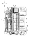
プリンターユニット(液体噴射装置本体)2は、枚葉の記録用紙Pを搬送経路Rに沿って送る搬送部61と、搬送経路Rの上方に配設されて記録用紙Pにインクジェット方式で印刷処理を行う印刷部62と、前面に配設されたパネル形式の操作部63と、搬送部61、印刷部62および操作部63を搭載した装置フレーム64と、これらを覆う装置ハウジング65と、を備える。
The printer unit (liquid ejecting apparatus main body) 2 includes a
図3は、プリンターユニット2の内部構造及びチューブ120の配置経路を示す側面視断面図である。
印刷部62は、装置フレーム64に支持されると共にY方向に幅一杯に延在する板金製のガイドフレーム71と、ガイドフレーム71に往復動自在に支持されたキャリッジユニット72と、キャリッジユニット72をガイドフレーム71に沿って往復動させるキャリッジ移動機構73(図2参照)と、を備える。
FIG. 3 is a side sectional view showing the internal structure of the
The
キャリッジユニット72は、係合スライダー部81aを介してガイドフレーム71に往復動自在に支持された箱状のキャリッジ81と、キャリッジ81の下面に一体に組み込まれたインクジェットヘッド83と、キャリッジ81に着脱自在に収納された4個のインクカートリッジ(1つのインクカートリッジアダプタ84と3つのインクカートリッジ85)を備える。
The
インクジェットヘッド(液体噴射ヘッド)83は、4色のインク滴を吐出する4連のノズル列(図示省略)を有する。4色のインクを貯留する4個のインクカートリッジ(インクカートリッジアダプタ84、インクカートリッジ85)をキャリッジ81に装着する。4個のインクカートリッジ(インクカートリッジアダプタ84、インクカートリッジ85)は、インクジェットヘッド83に上面側に直接接続される。
インクカートリッジアダプタ84には、後述するインク容器110からブラックインクが供給される。3つのインクカートリッジ85には、シアンマ、ゼンダ、イエローのインクが貯留される。
The ink jet head (liquid ejecting head) 83 has four nozzle rows (not shown) that eject ink droplets of four colors. Four ink cartridges (
Black ink is supplied to the
搬送部61は、記録用紙Pを右揃えでセットする可動式の用紙トレイ91と、用紙トレイ91から記録用紙Pを1枚ずつ分離して送り出す分離ローラー92と、分離ローラー92の下流側に位置し、記録用紙Pを搬送経路Rに沿って印刷部62に送り込む給紙ローラー93と、給紙ローラー93の下流側に位置し、インクジェットヘッド83に対面する媒体規制部材95と、媒体規制部材95の下流側に位置する鋸歯状のガイドローラー97と、ガイドローラー97の下流側に位置し、排出口100(図2参照)から記録用紙Pを送り出す排紙ローラー96と、を備える。
媒体規制部材95は、いわゆるプラテンに相当する。
The
The
分離ローラー92により、用紙トレイ91から送り込まれた記録用紙Pは、給紙ローラー93により、媒体規制部材95上を排紙ローラー96に向かってX方向に間欠送りされる(副走査)。
この間欠送りに同期して、キャリッジユニット72がX方向に往復動しながらインクを選択的に吐出して(主走査)、所望の印刷が行われる。
媒体規制部材95を越えてガイドローラー97に達した記録用紙Pの先端は、ガイドローラー97により上反り状態を矯正されるようにして、排紙ローラー96に送り込まれる。
このようにして、印刷が完了した記録用紙Pは、排紙ローラー96により、排出口100から前方に送り出される。
The recording paper P fed from the
In synchronization with this intermittent feed, the
The leading edge of the recording paper P that has reached the
In this way, the recording paper P for which printing has been completed is sent forward from the
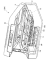
図4は、プリンターユニット2の内部構造及びチューブ120の配置経路を示す分解斜視図である。
図5は、プリンターユニット2の内部構造及びチューブ120の配置経路を示す上面図である。
装置フレーム64は、プリンターユニット2の各部を支持するフレームであり、一体成形された樹脂で構成される。
装置フレーム64は、ベースフレーム部64a、左右一対のサイドフレーム部64b、左右一対のフロントフレーム部64c及び左右一対のリアフレーム部64dを備える。
左右一対のサイドフレーム部64bは、ベースフレーム部64aに立設されて搬送部61の各構成部材およびガイドフレーム71を両側で支持する。
左右一対のフロントフレーム部64cは、ベースフレーム部64aの前部においてスキャナーユニット3の前部を支持すると共に、操作部63を支持する。
左右一対のリアフレーム部64dは、ベースフレーム部64aの後部において、開閉手段4を介してプリンターユニット2を開閉自在に支持する。
FIG. 4 is an exploded perspective view showing the internal structure of the
FIG. 5 is a top view showing the internal structure of the
The
The
The pair of left and right
The pair of left and right
The pair of left and right
一対のリアフレーム部64dは、装置ハウジング65の後部に開口した後部開口部を介して装置ハウジング65外部まで立設する。一対のリアフレーム部64dは、開閉手段4のプリンターユニット2側の構成部材が形成される。
The pair of
サイドフレーム部64bの前部には、ガイドローラー97及び補助ローラー99を支持する排紙フレーム101が配置される。補助ローラー(ローラー)99は、排紙ローラー96に対向配置される
排紙フレーム(フレーム部材)101は、キャリッジ81よりも前方(+X方向)側かつ下方(−Z方向)側に配置される。排紙フレーム101は、一対のサイドフレーム部64bの間に、キャリッジ81の走査方向(Y方向)に沿って水平に架け渡される。
A paper discharge frame 101 that supports the
排紙フレーム101から排出口100までの間には、比較的広い空間(前方内部空間S)が形成される。
前方内部空間Sには、黒色のインクを貯留するインク容器110が配置される(図2参照)。インク容器110のインク収容量は、インクカートリッジアダプタ84及びインクカートリッジ85のインク収容量と同一又はそれ以上である。
インク容器110は、前方内部空間Sの左端に配置される。前方内部空間Sのうち、左端領域は、記録用紙Pの搬送経路Rとは重ならない領域である。このため、前方内部空間Sの左端領域にインク容器110を配置したとしても、インク容器110と記録用紙Pが干渉することはない。
インク容器110は、前方内部空間Sの右端に配置しても同様である。
A relatively wide space (front internal space S) is formed between the discharge frame 101 and the
In the front internal space S, an
The
The same is true even if the
インク容器110とインクカートリッジアダプタ84の間には、インク容器110に収容されたインクをインクカートリッジアダプタ84に向けて供給するためのチューブ120が配置(配管)される。チューブ(液体供給チューブ)120は、黒色のインクを供給する1本のチューブ121からなる。
A
チューブ120は、インク容器110とインクカートリッジアダプタ84の間において、装置ハウジング65に対して上面開口部10に架け渡されるように取り付けられたチューブ固定部材170に固定される。チューブ120のうち、チューブ固定部材170とインクカートリッジアダプタ84の間の領域は、キャリッジ81の走査移動に伴って屈曲変形する可動領域120Fとなる。
The
チューブ固定部材170は、左右方向に延びる長尺の平板形の部材である(図4参照)。チューブ固定部材170は、上面開口部10の上方を走査方向(Y方向)に沿って水平に横切るように、装置ハウジング65に対して取り付けられる。チューブ固定部材170は、上面開口部10を挟んで装置ハウジング65左側と右側の間に架け渡されるようにして、装置ハウジング65に対して取り付けられる。チューブ固定部材170の両端は、接着剤や粘着テープなどを用いて装置ハウジング65に対して固定される。
チューブ固定部材170の左右方向中央には、チューブ121からなるチューブ120が固定される。
The
The
チューブ120の配置経路(配管ルート)をインク容器110からインクカートリッジアダプタ84に向かう方向(インクが流れる方向)に沿って説明する(図2、図5の順に説明する)。
The arrangement route (pipe route) of the
まず、図2に示すように、チューブ120は、インク容器110からチューブ固定部材170の左右方向中央に向けて架け渡される。チューブ120は、チューブ固定部材170の左右方向中央に対して、結束バンド等を用いて結束及び固定される。
First, as shown in FIG. 2, the
さらに、図5に示すように、チューブ120は、チューブ固定部材170に固定された後に、一旦+Y方向に向かうように配置される。その後、チューブ120は、U字形に折り返されて、+Y方向から−Y方向に反転する。チューブ120は、上下方向においてU字形に折り返される。
Furthermore, as shown in FIG. 5, after the
チューブ120は、−Y方向に反転した後に、キャリッジ81に収納された4個のインクカートリッジアダプタ84の上面において固定される。チューブ120は、インクカートリッジアダプタ84の上面において結束バンド等を用いて固定される。そして、チューブ120は、それぞれインクカートリッジアダプタ84に接続される。
The
チューブ120のうち、U字形に折り曲げられた領域は、キャリッジ81の走査移動に伴って屈曲変形する可動領域120Fとなる。可動領域120Fの長さは、キャリッジ81の走査移動を阻害しないように調整される。
A region of the
〔インク容器110の配置の変形例〕
図6は、インク容器110の配置の変形例を示す図である。
前方内部空間Sには、ブラック、シアンマ、ゼンダ、イエローのインクを貯留するインク容器110(インク容器111−114)の一部又は全部を配置することもできる。
[Modification of Arrangement of Ink Container 110]
FIG. 6 is a diagram illustrating a modified example of the arrangement of the
In the front internal space S, a part or all of the ink container 110 (
キャリッジ81には、4個のインクカートリッジアダプタ84が着脱自在に収納される。4個のインクカートリッジアダプタ84とインク容器110(4つのインク容器111−114)の間に、チューブ120(4本のチューブ121−124)が配置(配管)される。
Four
インク容器110のうち、インク容器111は、前方内部空間Sの左端に配置される。インク容器112は、前方内部空間Sの右端に配置される。インク容器113,114は、プリンターユニット2の外部領域である前方に配置される。
前方内部空間Sに収容するインク容器110とプリンターユニット2の外部に配置するインク容器110の組合せは、変更可能である。前方内部空間Sに対して全てのインク容器110を収容してもよい。
Of the
The combination of the
インク容器111,112に連結されたチューブ121,121は、それぞれチューブ固定部材170の左右方向中央に向けて架け渡される。インク容器113,114に連結されたチューブ123,124は、排出口100を経由した後に、それぞれチューブ固定部材170の左右方向中央に向けて架け渡される。
チューブ固定部材170の左右方向中央には、4本のチューブ121−124からなるチューブ120が固定される。
The
At the center in the left-right direction of the
以上説明したように、第一実施形態に係る複合機1では、プリンターユニット2の前方内部空間Sにインク容器110を収容するので、プリンターユニット2に対して追加工などを施す必要がほとんどない。インク容器110とキャリッジ81との距離が短いので、チューブ120の配置経路を容易に確保することができ、チューブ120の配置経路の最適化が図られる。
As described above, in the
〔第二実施形態〕
本発明の第二実施形態に係る複合機201について説明する。第一実施形態に係る複合機1と同一の構成や部材などについては、同一の符号を付してその説明を省略などする。
[Second Embodiment]
A
図7は、本発明の第二実施形態に係る複合機201の内部構造及びチューブ120の配置経路を示す分解斜視図である。
FIG. 7 is an exploded perspective view showing the internal structure of the
前方内部空間Sには、4つのインク容器110(インク容器111−114)を載置するインク載置台210が配置される。
インク載置台210は、左右方向に延びる長尺の平板部211及び平板部211の左右方向両端に配置された2つ脚部212を有し、板金を折り曲げ加工等して形成される。
平板部211の長手方向は、前方内部空間Sの左右方向の長さにほぼ一致する。2つ脚部212の長さ(高さ)は、例えば5−10mm程度である。
インク載置台210は、前方内部空間Sに対して、平板部211が走査方向(Y方向)に沿って水平に横切り、2つ脚部212が下方を向いて、設置される。
In the front internal space S, an ink placement table 210 for placing four ink containers 110 (
The ink mounting table 210 includes a long
The longitudinal direction of the
The ink placement table 210 is installed with the
前方内部空間Sの底面と平板部211の間の空間は、記録用紙Pの搬送経路Rである。インク載置台210は、記録用紙Pの搬送経路Rを跨ぐように配置される。
平板部211の上面には、4つのインク容器110が載置される。4つのインク容器110は、上面視する(+Z方向から見る)と、記録用紙Pの搬送経路Rに重なる領域に配置される。
A space between the bottom surface of the front internal space S and the
Four
キャリッジ81には、4個のインクカートリッジアダプタ84が着脱自在に収納される。4個のインクカートリッジアダプタ84とインク容器110(4つのインク容器111−114)の間に、チューブ120(4本のチューブ121−124)が配置(配管)される。
Four
4つのインク容器111−114は、平板部211の上面において、左右方向に向けて重なるように並べて配置される。4つのインク容器111−114は、その厚み方向に重ねられる。4つのインク容器111−114は、結束バンドなどを用いて束ねられる。
The four
4つのインク容器111−114に連結されたチューブ120(チューブ121−124)は、それぞれ直接、キャリッジ81のインクカートリッジアダプタ84に向けて架け渡される。チューブ120は、インクカートリッジアダプタ84の上面において結束バンド等を用いて固定される。そして、チューブ120は、それぞれインクカートリッジアダプタ84に接続される。
The tubes 120 (
チューブ120は、全ての領域が、キャリッジ81の走査移動に伴って屈曲変形する可動領域120Fとなる。可動領域120Fの長さは、キャリッジ81の走査移動を阻害しないように調整される。
The entire region of the
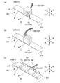
〔インク容器110の配置の変形例〕
図8は、インク容器110の配置の変形例を示す図である。(a)は、インク容器110を上下方向に向けて重ねて配置した場合を示す図である。(b)は、インク容器110を前後方向に向けて重ねて配置した場合を示す図である。(c)は、インク容器110を左右方向に向けて、その厚み方向とは異なる方向に重ね(並べ)て配置した場合を示す図である。
[Modification of Arrangement of Ink Container 110]
FIG. 8 is a diagram illustrating a modified example of the arrangement of the
インク容器110(4つのインク容器111−114)は、平板部211の上面において、上下方向、前後方向、左右方向に向けて、重なるように並べて配置することができる。4つのインク容器111−114の体積などに応じて、設置方向、重ねる方向を適宜設定することができる。
The ink containers 110 (four ink containers 111-114) can be arranged side by side on the upper surface of the
〔インク載置台の変形例〕
図9は、インク載置台220を示す図である。
インク載置台220は、インク載置台210の変形例である。インク載置台210に代えて、インク載置台220を用いることができる。
[Modified example of ink mounting table]
FIG. 9 is a view showing the ink mounting table 220.
The ink placement table 220 is a modification of the ink placement table 210. Instead of the ink mounting table 210, an ink mounting table 220 can be used.
インク載置台220は、インク載置台210の平板部211と同一形状の平板部221を有する。
一方、インク載置台210とは異なって、平板部211の左右方向両端において上方に向けて折り曲げられた2つの吊下部222を有する。2つの吊下部222は、前方内部空間Sを露出させる上面開口部10の縁部に引っ掛けられる形状を有する。
インク載置台220は、前方内部空間Sに対して、平板部221が走査方向(Y方向)に沿って水平に横切り、2つの吊下部222が上方を向いて、設置される。2つの吊下部222は、上面開口部10の縁部に引っ掛かるため、平板部221と前方内部空間Sの底面との間に、記録用紙Pの搬送経路Rが確保される。
平板部221の上面には、4つのインク容器110が載置される。4つのインク容器110は、上面視する(+Z方向から見る)と、記録用紙Pの搬送経路Rに重なる領域に配置される。
The ink placement table 220 has a flat plate portion 221 having the same shape as the
On the other hand, unlike the ink placement table 210, the
The ink mounting table 220 is installed with the flat plate portion 221 horizontally traversing along the scanning direction (Y direction) with respect to the front internal space S, and the two suspended
Four
以上説明したように、第二実施形態に係る複合機201においても、第一実施形態に係る複合機1と同一の効果を奏する。すなわち、プリンターユニット2の前方内部空間Sにインク容器110を収容するので、プリンターユニット2に対して追加工などを施す必要がない。インク容器110とキャリッジ81との距離が短いので、チューブ120の配置経路を容易に確保することができ、チューブ120の配置経路の最適化が図られる。
As described above, the
上述した実施の形態において示した各構成部材の諸形状や組み合わせ等は一例であって、本発明の主旨から逸脱しない範囲において設計要求等に基づき種々変更可能である。 Various shapes, combinations, and the like of the constituent members shown in the above-described embodiments are merely examples, and various modifications can be made based on design requirements and the like without departing from the gist of the present invention.
図10は、操作部63を前方側に傾斜させた状態を示す図である。
複合機1,201は、操作部63を前方側に傾斜させることが可能である。操作部63を前方側に傾斜させるための傾斜機構(不図示)が操作部63の裏面側(後方側)に設けられる。操作部63及び傾斜機構は、排出口100の上方に設けられる。このため、操作部63が垂直状態の場合に比べて、操作部63が前方傾斜状態の場合の方が、前方内部空間Sが広くなる。
そこで、複合機1,201では、操作部63を前方側に傾斜させた状態で固定する。傾斜機構が動作できないようにして、操作部63の傾斜角度が最も大きい状態を確保する。
これにより、前方内部空間Sが広くなり、より多くのインク容器110を設置することが可能となる。
FIG. 10 is a diagram illustrating a state in which the
The
Therefore, in the
As a result, the front internal space S is widened, and
図11は、スキャナーユニット3に配置された操作部66を示す図である。
複合機1,201は、プリンターユニット2に対して傾斜可能に配置された操作部63に代えて、スキャナーユニット3に配置された操作部66を備えてもよい。
スキャナーユニット3に配置された操作部66は、スキャナーユニット3に対して傾斜させることはできない。スキャナーユニット3を閉じたときは、操作部63が垂直状態となる。
操作部66を用いた場合には、操作部66を前方側に傾斜させるための傾斜機構を必要としないので、操作部63を用いた場合に比べて、前方内部空間Sが広くなる。
これにより、前方内部空間Sが広くなり、より多くのインク容器110を設置することが可能となる。
FIG. 11 is a diagram showing the
The
The
When the
As a result, the front internal space S is widened, and
インク容器110が4つ、チューブ120が4本のチューブの場合に限らない。インク容器110が6つ、チューブ120が6本のチューブであってもよい。
The present invention is not limited to the case where there are four
キャリッジ81は、インクカートリッジアダプタ84を搭載しておらず、インク容器110からチューブ120を介して直接インクが供給される構成であってもよい。
The
インク容器110を備える装置としては、液体噴射装置に限らず、液体を消費する装置であればよい。
An apparatus including the
液体噴射装置として、インク等の液体を噴射する液体噴射装置を例にして説明したが、インク以外の他の液体を噴射したり吐出したりする液体噴射装置に適用することができる。液体噴射装置が噴射可能な液体は、機能材料の粒子が分散又は溶解されている液状体、ジェル状の流状体を含む。
液体噴射装置から噴射される液体としては、インクのみならず、特定の用途に対応する液体を適用可能である。
The liquid ejecting apparatus that ejects a liquid such as ink has been described as an example of the liquid ejecting apparatus. However, the present invention can be applied to a liquid ejecting apparatus that ejects or discharges liquid other than ink. The liquid that can be ejected by the liquid ejecting apparatus includes a liquid material in which particles of the functional material are dispersed or dissolved, and a gel-like fluid.
As the liquid ejected from the liquid ejecting apparatus, not only ink but also a liquid corresponding to a specific application can be applied.
1,201…複合機(液体噴射装置)、 2…プリンターユニット(液体噴射装置本体)、 3…スキャナーユニット(蓋体,画像読取装置)、 10…上面開口部、 63,66…操作部、 81…キャリッジ、 83…インクジェットヘッド(液体噴射ヘッド)、 84…インクカートリッジアダプタ、 100…排出口、 110…インク容器(液体収容体)、 120…チューブ(液体供給チューブ)、 170…チューブ固定部材、 210…インク載置台、 211…平板部、 212…脚部、 220…インク載置台、 221…平板部、 222…吊下部、 P…記録用紙(記録媒体)、 R…搬送経路 、S…前方内部空間(内部空間)
DESCRIPTION OF SYMBOLS 1,201 ... Multifunction machine (liquid ejecting apparatus), 2 ... Printer unit (liquid ejecting apparatus main body), 3 ... Scanner unit (lid body, image reading apparatus), 10 ... Upper surface opening part, 63, 66 ... Operation part, 81 DESCRIPTION OF SYMBOLS ...
Claims (3)
前記液体が収容された液体収容体から送られる液体を前記液体噴射ヘッドへと導き、前
記液体噴射ヘッドの前記移動に伴って追従変形する変形可動部を有する液体供給チューブ
と、
前記液体噴射ヘッドによって、記録が行われた前記記録媒体を、排出口に向けて搬送する排紙ローラーと、
前記排紙ローラーに対向配置される補助ローラーを支持する排紙フレームと、
前記排紙フレームを架け渡す一対のサイドフレームと、
前記記録媒体の搬送方向における前記排紙ローラーと前記排出口との間および前記キャリッジ移動方向における一対のサイドフレームの間に形成された内部空間と、
を備える液体噴射装置において、
前記内部空間には、前記キャリッジ移動方向において、前記記録媒体が前記排紙ローラーから前記排出口に向かう搬送経路と、前記搬送経路と重ならない領域とが形成され、
前記液体収容体は、前記内部空間における前記搬送経路と前記サイドフレームとの間の前記搬送経路と重ならない領域であり、平板部を有するインク載置台に配置されることを特徴とする液体噴射装置。 A liquid ejecting apparatus main body having a liquid ejecting head mounted on a carriage and ejecting liquid toward a recording medium;
A liquid supply tube having a deformable movable portion that guides the liquid sent from the liquid container containing the liquid to the liquid ejecting head and deforms following the movement of the liquid ejecting head;
A paper discharge roller for transporting the recording medium on which recording has been performed by the liquid ejecting head toward a discharge port;
A paper discharge frame that supports an auxiliary roller disposed opposite to the paper discharge roller;
A pair of side frames that span the paper discharge frame;
An internal space formed between the discharge roller and the discharge port in the conveyance direction of the recording medium and between a pair of side frames in the carriage movement direction;
In a liquid ejecting apparatus comprising:
Wherein the inner space, in the carriage movement direction, a conveying path which the recording medium is directed to the exhaust exit from the discharge roller, a region that does not overlap with the transport path is formed,
The liquid container is a region that does not overlap the transport path between the transport path and the side frame in the internal space , and is disposed on an ink placement table having a flat plate portion. .
配置され、
前記内部空間が、前記画像読取装置と高さ方向において重畳する領域に形成されることを特徴とする請求項1または請求項2に記載の液体噴射装置。 An image reading device that reads an image of a recording medium is disposed above the liquid ejecting apparatus main body so as to be in close contact,
The liquid ejecting apparatus according to claim 1, wherein the internal space is formed in a region overlapping with the image reading device in a height direction.
Priority Applications (13)
| Application Number | Priority Date | Filing Date | Title |
|---|---|---|---|
| JP2012047697A JP6161869B2 (en) | 2012-03-05 | 2012-03-05 | Liquid ejector |
| EP13757373.9A EP2823963A4 (en) | 2012-03-05 | 2013-03-01 | Liquid ejection device |
| RU2016101862A RU2693511C2 (en) | 2012-03-05 | 2013-03-01 | Liquid ejection apparatus |
| CN201610139472.4A CN105799332B (en) | 2012-03-05 | 2013-03-01 | Liquid injection apparatus |
| CN201610140024.6A CN105774254B (en) | 2012-03-05 | 2013-03-01 | Liquid injection apparatus |
| PCT/JP2013/001285 WO2013132810A1 (en) | 2012-03-05 | 2013-03-01 | Liquid ejection device |
| CN201380012538.8A CN104144790B (en) | 2012-03-05 | 2013-03-01 | Liquid injection apparatus |
| IN5821DEN2014 IN2014DN05821A (en) | 2012-03-05 | 2013-03-01 | |
| RU2014140184/12A RU2590885C2 (en) | 2012-03-05 | 2013-03-01 | Fluid ejection device |
| US13/783,717 US9283765B2 (en) | 2012-03-05 | 2013-03-04 | Liquid ejecting apparatus |
| TW102204156U TWM466793U (en) | 2012-03-05 | 2013-03-05 | Liquid ejecting apparatus |
| US14/595,018 US9944100B2 (en) | 2012-03-05 | 2015-01-12 | Liquid ejecting apparatus |
| US15/074,874 US9944101B2 (en) | 2012-03-05 | 2016-03-18 | Liquid ejecting apparatus |
Applications Claiming Priority (1)
| Application Number | Priority Date | Filing Date | Title |
|---|---|---|---|
| JP2012047697A JP6161869B2 (en) | 2012-03-05 | 2012-03-05 | Liquid ejector |
Related Child Applications (2)
| Application Number | Title | Priority Date | Filing Date |
|---|---|---|---|
| JP2016043122A Division JP6439720B2 (en) | 2016-03-07 | 2016-03-07 | Liquid ejector |
| JP2016043123A Division JP6439721B2 (en) | 2016-03-07 | 2016-03-07 | Liquid ejector |
Publications (3)
| Publication Number | Publication Date |
|---|---|
| JP2013180542A JP2013180542A (en) | 2013-09-12 |
| JP2013180542A5 JP2013180542A5 (en) | 2015-04-02 |
| JP6161869B2 true JP6161869B2 (en) | 2017-07-12 |
Family
ID=49116306
Family Applications (1)
| Application Number | Title | Priority Date | Filing Date |
|---|---|---|---|
| JP2012047697A Active JP6161869B2 (en) | 2012-03-05 | 2012-03-05 | Liquid ejector |
Country Status (8)
| Country | Link |
|---|---|
| US (3) | US9283765B2 (en) |
| EP (1) | EP2823963A4 (en) |
| JP (1) | JP6161869B2 (en) |
| CN (3) | CN104144790B (en) |
| IN (1) | IN2014DN05821A (en) |
| RU (2) | RU2693511C2 (en) |
| TW (1) | TWM466793U (en) |
| WO (1) | WO2013132810A1 (en) |
Families Citing this family (6)
| Publication number | Priority date | Publication date | Assignee | Title |
|---|---|---|---|---|
| JP6161869B2 (en) | 2012-03-05 | 2017-07-12 | セイコーエプソン株式会社 | Liquid ejector |
| JP6330331B2 (en) * | 2014-01-14 | 2018-05-30 | セイコーエプソン株式会社 | Liquid container, liquid ejecting system, liquid ejecting apparatus |
| TWI644730B (en) * | 2014-02-05 | 2018-12-21 | 山保工業股份有限公司 | Liquid spray nozzle |
| JP6922362B2 (en) * | 2017-04-10 | 2021-08-18 | セイコーエプソン株式会社 | Printing device and control method of printing device |
| JP7143656B2 (en) * | 2018-07-13 | 2022-09-29 | ブラザー工業株式会社 | printer |
| JP7223255B2 (en) * | 2018-12-26 | 2023-02-16 | セイコーエプソン株式会社 | Inkjet printer, ink supply unit |
Family Cites Families (50)
| Publication number | Priority date | Publication date | Assignee | Title |
|---|---|---|---|---|
| WO1995031335A1 (en) * | 1994-05-17 | 1995-11-23 | Seiko Epson Corporation | Ink jet recorder and method of cleaning recording head |
| US6170937B1 (en) * | 1997-01-21 | 2001-01-09 | Hewlett-Packard Company | Ink container refurbishment method |
| JP3376216B2 (en) | 1995-07-18 | 2003-02-10 | キヤノン株式会社 | Image forming device |
| JPH10217496A (en) * | 1997-02-06 | 1998-08-18 | Citizen Watch Co Ltd | Ink jet recording device |
| US6233586B1 (en) * | 1998-04-01 | 2001-05-15 | International Business Machines Corp. | Federated searching of heterogeneous datastores using a federated query object |
| JP3768725B2 (en) * | 1998-06-15 | 2006-04-19 | キヤノン株式会社 | Inkjet recording device |
| JP3900798B2 (en) * | 2000-07-10 | 2007-04-04 | コニカミノルタホールディングス株式会社 | Inkjet head recovery device, inkjet image recording device |
| JP3818194B2 (en) * | 2002-03-28 | 2006-09-06 | ブラザー工業株式会社 | Recording device |
| US20030076391A1 (en) | 2001-10-24 | 2003-04-24 | Wilson John F. | Supply adaptor for an on-axis printer |
| JP2003200597A (en) * | 2001-10-25 | 2003-07-15 | Matsushita Electric Ind Co Ltd | Ink jet recorder |
| JP4196176B2 (en) | 2002-03-07 | 2008-12-17 | セイコーエプソン株式会社 | Optical disc ejection device and ink jet recording apparatus equipped with the ejection device |
| EP1348557B1 (en) * | 2002-03-28 | 2004-09-08 | Brother Kogyo Kabushiki Kaisha | Ink cartridge and method of production thereof |
| JP2003326732A (en) | 2002-05-16 | 2003-11-19 | Canon Inc | Ink supply device |
| US6719414B2 (en) | 2002-07-31 | 2004-04-13 | Hewlett-Packard Development Company, Lp | Ink tube carrier for a printer, and method |
| CA2395836C (en) * | 2002-08-07 | 2007-12-04 | Per G. Akermalm | Expanded ink supply system for inkjet printers |
| US7008051B2 (en) * | 2002-10-10 | 2006-03-07 | Akermalm Per G | Expanded ink supply system for ink jet printers |
| JP2004345247A (en) * | 2003-05-22 | 2004-12-09 | Matsushita Electric Ind Co Ltd | Ink jet type recording device |
| JP4635426B2 (en) * | 2003-10-22 | 2011-02-23 | ブラザー工業株式会社 | Image forming apparatus |
| US7303271B2 (en) * | 2003-10-24 | 2007-12-04 | Brother Kogyo Kabushiki Kaisha | Ink jet printer |
| JP4595425B2 (en) * | 2004-07-28 | 2010-12-08 | ブラザー工業株式会社 | Recording device |
| US7712891B2 (en) * | 2003-12-26 | 2010-05-11 | Brother Kogyo Kabushiki Kaisha | Image-forming device |
| DE602005013135D1 (en) * | 2004-03-05 | 2009-04-23 | Brother Ind Ltd | The image recording device |
| JP2006007678A (en) | 2004-06-29 | 2006-01-12 | Ricoh Co Ltd | Maintenance and recovery device of liquid ejector, and image forming apparatus |
| JP2006102985A (en) * | 2004-09-30 | 2006-04-20 | Seiko Epson Corp | Liquid jetting apparatus |
| JP2006110946A (en) * | 2004-10-18 | 2006-04-27 | Ricoh Co Ltd | Image forming device |
| JP4613616B2 (en) | 2005-01-05 | 2011-01-19 | セイコーエプソン株式会社 | Liquid container module and liquid ejecting apparatus |
| JP4726155B2 (en) * | 2005-02-22 | 2011-07-20 | 株式会社リコー | Image forming apparatus |
| JP4725182B2 (en) | 2005-04-28 | 2011-07-13 | セイコーエプソン株式会社 | Method for manufacturing liquid supply system and liquid supply system |
| EP1880856B1 (en) * | 2005-05-13 | 2012-11-07 | Brother Kogyo Kabushiki Kaisha | Ink jet recording apparatus |
| CN2825289Y (en) | 2005-10-25 | 2006-10-11 | 珠海天威技术开发有限公司 | Connecting device for continuous ink-feeding system |
| JP2007152725A (en) * | 2005-12-05 | 2007-06-21 | Brother Ind Ltd | Recovering apparatus for inkjet printer |
| JP4569507B2 (en) * | 2006-03-31 | 2010-10-27 | ブラザー工業株式会社 | Inkjet recording device |
| US7385116B2 (en) * | 2006-04-28 | 2008-06-10 | Monsanto Technology Llc | Soybean variety 0240187 |
| JP4337855B2 (en) * | 2006-09-20 | 2009-09-30 | ブラザー工業株式会社 | Scanning device |
| JP5224754B2 (en) * | 2006-11-29 | 2013-07-03 | キヤノン株式会社 | Inkjet recording device |
| US7950764B2 (en) * | 2007-03-16 | 2011-05-31 | Seiko Epson Corporation | Pressure regulating mechanism and liquid ejecting apparatus |
| US8096651B2 (en) * | 2007-03-19 | 2012-01-17 | Ricoh Company, Ltd. | Ink-jet recording method, ink, ink cartridge, recording apparatus, and recorded matter |
| JP2008229974A (en) * | 2007-03-19 | 2008-10-02 | Brother Ind Ltd | Printer system, and main printer and sub printer to be used therefor |
| JP2008238787A (en) | 2007-03-29 | 2008-10-09 | Seiko Epson Corp | Liquid supply system, liquid supply device, and liquid supply method |
| JP4766011B2 (en) * | 2007-06-20 | 2011-09-07 | セイコーエプソン株式会社 | Fluid ejecting apparatus and manufacturing method thereof |
| EP2240034B1 (en) | 2008-01-07 | 2014-03-26 | PCH Technologies | A printer for edible sheets |
| JP4900414B2 (en) * | 2008-04-28 | 2012-03-21 | ブラザー工業株式会社 | Liquid ejection device |
| US8182082B2 (en) * | 2009-03-05 | 2012-05-22 | Hewlett-Packard Development Company, L.P. | Printer accessory module for high capacity printing |
| JP5464936B2 (en) * | 2009-07-31 | 2014-04-09 | キヤノン株式会社 | Ink tank and pigment ink stirring system including the same |
| JP5471599B2 (en) * | 2010-03-02 | 2014-04-16 | 株式会社リコー | Image forming apparatus |
| JP2011218606A (en) * | 2010-04-06 | 2011-11-04 | Seiko Epson Corp | Liquid ejection device |
| BR112012005682A2 (en) * | 2010-07-15 | 2016-02-23 | Seiko Epson Corp | liquid container and liquid ejection system |
| JP5552931B2 (en) * | 2010-07-15 | 2014-07-16 | セイコーエプソン株式会社 | Liquid container and liquid ejection system |
| US20130155450A1 (en) * | 2011-12-19 | 2013-06-20 | Brother Kogyo Kabushiki Kaisha | Recording apparatus having a plurality of antennas |
| JP6161869B2 (en) | 2012-03-05 | 2017-07-12 | セイコーエプソン株式会社 | Liquid ejector |
-
2012
- 2012-03-05 JP JP2012047697A patent/JP6161869B2/en active Active
-
2013
- 2013-03-01 CN CN201380012538.8A patent/CN104144790B/en active Active
- 2013-03-01 CN CN201610139472.4A patent/CN105799332B/en active Active
- 2013-03-01 CN CN201610140024.6A patent/CN105774254B/en active Active
- 2013-03-01 IN IN5821DEN2014 patent/IN2014DN05821A/en unknown
- 2013-03-01 RU RU2016101862A patent/RU2693511C2/en active
- 2013-03-01 EP EP13757373.9A patent/EP2823963A4/en not_active Ceased
- 2013-03-01 WO PCT/JP2013/001285 patent/WO2013132810A1/en active Application Filing
- 2013-03-01 RU RU2014140184/12A patent/RU2590885C2/en active
- 2013-03-04 US US13/783,717 patent/US9283765B2/en active Active
- 2013-03-05 TW TW102204156U patent/TWM466793U/en not_active IP Right Cessation
-
2015
- 2015-01-12 US US14/595,018 patent/US9944100B2/en active Active
-
2016
- 2016-03-18 US US15/074,874 patent/US9944101B2/en active Active
Also Published As
| Publication number | Publication date |
|---|---|
| US9283765B2 (en) | 2016-03-15 |
| US20140002552A1 (en) | 2014-01-02 |
| EP2823963A1 (en) | 2015-01-14 |
| CN104144790A (en) | 2014-11-12 |
| WO2013132810A1 (en) | 2013-09-12 |
| CN105799332B (en) | 2018-05-04 |
| JP2013180542A (en) | 2013-09-12 |
| RU2016101862A (en) | 2018-11-21 |
| EP2823963A4 (en) | 2017-04-26 |
| CN104144790B (en) | 2016-09-21 |
| US9944100B2 (en) | 2018-04-17 |
| US20160200123A1 (en) | 2016-07-14 |
| TWM466793U (en) | 2013-12-01 |
| RU2693511C2 (en) | 2019-07-03 |
| US20150124026A1 (en) | 2015-05-07 |
| CN105799332A (en) | 2016-07-27 |
| CN105774254A (en) | 2016-07-20 |
| CN105774254B (en) | 2018-12-11 |
| IN2014DN05821A (en) | 2015-05-15 |
| RU2590885C2 (en) | 2016-07-10 |
| RU2016101862A3 (en) | 2019-04-15 |
| RU2014140184A (en) | 2016-04-20 |
| US9944101B2 (en) | 2018-04-17 |
Similar Documents
| Publication | Publication Date | Title |
|---|---|---|
| JP4635426B2 (en) | Image forming apparatus | |
| JP4277223B2 (en) | Paper feeding device and image recording apparatus having the same | |
| JP6161869B2 (en) | Liquid ejector | |
| US9315031B2 (en) | Ink jet recording apparatus | |
| JP4277224B2 (en) | Paper feeding device and image recording apparatus having the same | |
| JP6707838B2 (en) | Liquid consumption device | |
| JP3818194B2 (en) | Recording device | |
| WO2013128924A1 (en) | Liquid-ejection device | |
| JP6119338B2 (en) | Image recording device | |
| JP6182828B2 (en) | Liquid ejector | |
| JP5974358B2 (en) | Liquid ejector | |
| JP6179066B2 (en) | Liquid ejector | |
| JP6439721B2 (en) | Liquid ejector | |
| JP6439720B2 (en) | Liquid ejector | |
| JP4941334B2 (en) | Inkjet recording device | |
| JP2015110280A (en) | Recording device | |
| WO2016021171A1 (en) | Composite device | |
| JP2018065363A (en) | Supply device | |
| US20130083138A1 (en) | Liquid ejection apparatus | |
| JP6682806B2 (en) | Liquid consumption device | |
| JP6296377B2 (en) | Liquid cartridge | |
| JP2012176581A (en) | Image forming apparatus | |
| JP2013180543A (en) | Liquid ejecting apparatus | |
| JP2005219235A (en) | Inkjet type recording apparatus and liquid jetting apparatus |
Legal Events
| Date | Code | Title | Description |
|---|---|---|---|
| RD04 | Notification of resignation of power of attorney |
Free format text: JAPANESE INTERMEDIATE CODE: A7424 Effective date: 20150107 |
|
| A521 | Request for written amendment filed |
Free format text: JAPANESE INTERMEDIATE CODE: A523 Effective date: 20150210 |
|
| A621 | Written request for application examination |
Free format text: JAPANESE INTERMEDIATE CODE: A621 Effective date: 20150210 |
|
| A131 | Notification of reasons for refusal |
Free format text: JAPANESE INTERMEDIATE CODE: A131 Effective date: 20160112 |
|
| A521 | Request for written amendment filed |
Free format text: JAPANESE INTERMEDIATE CODE: A523 Effective date: 20160307 |
|
| A02 | Decision of refusal |
Free format text: JAPANESE INTERMEDIATE CODE: A02 Effective date: 20160405 |
|
| A521 | Request for written amendment filed |
Free format text: JAPANESE INTERMEDIATE CODE: A523 Effective date: 20160621 |
|
| A911 | Transfer to examiner for re-examination before appeal (zenchi) |
Free format text: JAPANESE INTERMEDIATE CODE: A911 Effective date: 20160628 |
|
| A912 | Re-examination (zenchi) completed and case transferred to appeal board |
Free format text: JAPANESE INTERMEDIATE CODE: A912 Effective date: 20160805 |
|
| A521 | Request for written amendment filed |
Free format text: JAPANESE INTERMEDIATE CODE: A523 Effective date: 20170314 |
|
| A61 | First payment of annual fees (during grant procedure) |
Free format text: JAPANESE INTERMEDIATE CODE: A61 Effective date: 20170614 |
|
| R150 | Certificate of patent or registration of utility model |
Ref document number: 6161869 Country of ref document: JP Free format text: JAPANESE INTERMEDIATE CODE: R150 |