JP6160928B2 - In-vehicle device and charge / discharge system - Google Patents
In-vehicle device and charge / discharge system Download PDFInfo
- Publication number
- JP6160928B2 JP6160928B2 JP2014500920A JP2014500920A JP6160928B2 JP 6160928 B2 JP6160928 B2 JP 6160928B2 JP 2014500920 A JP2014500920 A JP 2014500920A JP 2014500920 A JP2014500920 A JP 2014500920A JP 6160928 B2 JP6160928 B2 JP 6160928B2
- Authority
- JP
- Japan
- Prior art keywords
- vehicle
- charger
- discharger
- charge
- charging
- Prior art date
- Legal status (The legal status is an assumption and is not a legal conclusion. Google has not performed a legal analysis and makes no representation as to the accuracy of the status listed.)
- Active
Links
Images


Classifications
-
- B—PERFORMING OPERATIONS; TRANSPORTING
- B60—VEHICLES IN GENERAL
- B60L—PROPULSION OF ELECTRICALLY-PROPELLED VEHICLES; SUPPLYING ELECTRIC POWER FOR AUXILIARY EQUIPMENT OF ELECTRICALLY-PROPELLED VEHICLES; ELECTRODYNAMIC BRAKE SYSTEMS FOR VEHICLES IN GENERAL; MAGNETIC SUSPENSION OR LEVITATION FOR VEHICLES; MONITORING OPERATING VARIABLES OF ELECTRICALLY-PROPELLED VEHICLES; ELECTRIC SAFETY DEVICES FOR ELECTRICALLY-PROPELLED VEHICLES
- B60L53/00—Methods of charging batteries, specially adapted for electric vehicles; Charging stations or on-board charging equipment therefor; Exchange of energy storage elements in electric vehicles
- B60L53/10—Methods of charging batteries, specially adapted for electric vehicles; Charging stations or on-board charging equipment therefor; Exchange of energy storage elements in electric vehicles characterised by the energy transfer between the charging station and the vehicle
- B60L53/14—Conductive energy transfer
-
- B—PERFORMING OPERATIONS; TRANSPORTING
- B60—VEHICLES IN GENERAL
- B60L—PROPULSION OF ELECTRICALLY-PROPELLED VEHICLES; SUPPLYING ELECTRIC POWER FOR AUXILIARY EQUIPMENT OF ELECTRICALLY-PROPELLED VEHICLES; ELECTRODYNAMIC BRAKE SYSTEMS FOR VEHICLES IN GENERAL; MAGNETIC SUSPENSION OR LEVITATION FOR VEHICLES; MONITORING OPERATING VARIABLES OF ELECTRICALLY-PROPELLED VEHICLES; ELECTRIC SAFETY DEVICES FOR ELECTRICALLY-PROPELLED VEHICLES
- B60L53/00—Methods of charging batteries, specially adapted for electric vehicles; Charging stations or on-board charging equipment therefor; Exchange of energy storage elements in electric vehicles
- B60L53/30—Constructional details of charging stations
- B60L53/305—Communication interfaces
-
- B—PERFORMING OPERATIONS; TRANSPORTING
- B60—VEHICLES IN GENERAL
- B60L—PROPULSION OF ELECTRICALLY-PROPELLED VEHICLES; SUPPLYING ELECTRIC POWER FOR AUXILIARY EQUIPMENT OF ELECTRICALLY-PROPELLED VEHICLES; ELECTRODYNAMIC BRAKE SYSTEMS FOR VEHICLES IN GENERAL; MAGNETIC SUSPENSION OR LEVITATION FOR VEHICLES; MONITORING OPERATING VARIABLES OF ELECTRICALLY-PROPELLED VEHICLES; ELECTRIC SAFETY DEVICES FOR ELECTRICALLY-PROPELLED VEHICLES
- B60L53/00—Methods of charging batteries, specially adapted for electric vehicles; Charging stations or on-board charging equipment therefor; Exchange of energy storage elements in electric vehicles
- B60L53/50—Charging stations characterised by energy-storage or power-generation means
- B60L53/51—Photovoltaic means
-
- B—PERFORMING OPERATIONS; TRANSPORTING
- B60—VEHICLES IN GENERAL
- B60L—PROPULSION OF ELECTRICALLY-PROPELLED VEHICLES; SUPPLYING ELECTRIC POWER FOR AUXILIARY EQUIPMENT OF ELECTRICALLY-PROPELLED VEHICLES; ELECTRODYNAMIC BRAKE SYSTEMS FOR VEHICLES IN GENERAL; MAGNETIC SUSPENSION OR LEVITATION FOR VEHICLES; MONITORING OPERATING VARIABLES OF ELECTRICALLY-PROPELLED VEHICLES; ELECTRIC SAFETY DEVICES FOR ELECTRICALLY-PROPELLED VEHICLES
- B60L53/00—Methods of charging batteries, specially adapted for electric vehicles; Charging stations or on-board charging equipment therefor; Exchange of energy storage elements in electric vehicles
- B60L53/50—Charging stations characterised by energy-storage or power-generation means
- B60L53/54—Fuel cells
-
- B—PERFORMING OPERATIONS; TRANSPORTING
- B60—VEHICLES IN GENERAL
- B60L—PROPULSION OF ELECTRICALLY-PROPELLED VEHICLES; SUPPLYING ELECTRIC POWER FOR AUXILIARY EQUIPMENT OF ELECTRICALLY-PROPELLED VEHICLES; ELECTRODYNAMIC BRAKE SYSTEMS FOR VEHICLES IN GENERAL; MAGNETIC SUSPENSION OR LEVITATION FOR VEHICLES; MONITORING OPERATING VARIABLES OF ELECTRICALLY-PROPELLED VEHICLES; ELECTRIC SAFETY DEVICES FOR ELECTRICALLY-PROPELLED VEHICLES
- B60L53/00—Methods of charging batteries, specially adapted for electric vehicles; Charging stations or on-board charging equipment therefor; Exchange of energy storage elements in electric vehicles
- B60L53/60—Monitoring or controlling charging stations
- B60L53/63—Monitoring or controlling charging stations in response to network capacity
-
- B—PERFORMING OPERATIONS; TRANSPORTING
- B60—VEHICLES IN GENERAL
- B60L—PROPULSION OF ELECTRICALLY-PROPELLED VEHICLES; SUPPLYING ELECTRIC POWER FOR AUXILIARY EQUIPMENT OF ELECTRICALLY-PROPELLED VEHICLES; ELECTRODYNAMIC BRAKE SYSTEMS FOR VEHICLES IN GENERAL; MAGNETIC SUSPENSION OR LEVITATION FOR VEHICLES; MONITORING OPERATING VARIABLES OF ELECTRICALLY-PROPELLED VEHICLES; ELECTRIC SAFETY DEVICES FOR ELECTRICALLY-PROPELLED VEHICLES
- B60L53/00—Methods of charging batteries, specially adapted for electric vehicles; Charging stations or on-board charging equipment therefor; Exchange of energy storage elements in electric vehicles
- B60L53/60—Monitoring or controlling charging stations
- B60L53/64—Optimising energy costs, e.g. responding to electricity rates
-
- B—PERFORMING OPERATIONS; TRANSPORTING
- B60—VEHICLES IN GENERAL
- B60L—PROPULSION OF ELECTRICALLY-PROPELLED VEHICLES; SUPPLYING ELECTRIC POWER FOR AUXILIARY EQUIPMENT OF ELECTRICALLY-PROPELLED VEHICLES; ELECTRODYNAMIC BRAKE SYSTEMS FOR VEHICLES IN GENERAL; MAGNETIC SUSPENSION OR LEVITATION FOR VEHICLES; MONITORING OPERATING VARIABLES OF ELECTRICALLY-PROPELLED VEHICLES; ELECTRIC SAFETY DEVICES FOR ELECTRICALLY-PROPELLED VEHICLES
- B60L53/00—Methods of charging batteries, specially adapted for electric vehicles; Charging stations or on-board charging equipment therefor; Exchange of energy storage elements in electric vehicles
- B60L53/60—Monitoring or controlling charging stations
- B60L53/65—Monitoring or controlling charging stations involving identification of vehicles or their battery types
-
- B—PERFORMING OPERATIONS; TRANSPORTING
- B60—VEHICLES IN GENERAL
- B60L—PROPULSION OF ELECTRICALLY-PROPELLED VEHICLES; SUPPLYING ELECTRIC POWER FOR AUXILIARY EQUIPMENT OF ELECTRICALLY-PROPELLED VEHICLES; ELECTRODYNAMIC BRAKE SYSTEMS FOR VEHICLES IN GENERAL; MAGNETIC SUSPENSION OR LEVITATION FOR VEHICLES; MONITORING OPERATING VARIABLES OF ELECTRICALLY-PROPELLED VEHICLES; ELECTRIC SAFETY DEVICES FOR ELECTRICALLY-PROPELLED VEHICLES
- B60L53/00—Methods of charging batteries, specially adapted for electric vehicles; Charging stations or on-board charging equipment therefor; Exchange of energy storage elements in electric vehicles
- B60L53/60—Monitoring or controlling charging stations
- B60L53/66—Data transfer between charging stations and vehicles
- B60L53/665—Methods related to measuring, billing or payment
-
- B—PERFORMING OPERATIONS; TRANSPORTING
- B60—VEHICLES IN GENERAL
- B60L—PROPULSION OF ELECTRICALLY-PROPELLED VEHICLES; SUPPLYING ELECTRIC POWER FOR AUXILIARY EQUIPMENT OF ELECTRICALLY-PROPELLED VEHICLES; ELECTRODYNAMIC BRAKE SYSTEMS FOR VEHICLES IN GENERAL; MAGNETIC SUSPENSION OR LEVITATION FOR VEHICLES; MONITORING OPERATING VARIABLES OF ELECTRICALLY-PROPELLED VEHICLES; ELECTRIC SAFETY DEVICES FOR ELECTRICALLY-PROPELLED VEHICLES
- B60L53/00—Methods of charging batteries, specially adapted for electric vehicles; Charging stations or on-board charging equipment therefor; Exchange of energy storage elements in electric vehicles
- B60L53/60—Monitoring or controlling charging stations
- B60L53/68—Off-site monitoring or control, e.g. remote control
-
- B—PERFORMING OPERATIONS; TRANSPORTING
- B60—VEHICLES IN GENERAL
- B60L—PROPULSION OF ELECTRICALLY-PROPELLED VEHICLES; SUPPLYING ELECTRIC POWER FOR AUXILIARY EQUIPMENT OF ELECTRICALLY-PROPELLED VEHICLES; ELECTRODYNAMIC BRAKE SYSTEMS FOR VEHICLES IN GENERAL; MAGNETIC SUSPENSION OR LEVITATION FOR VEHICLES; MONITORING OPERATING VARIABLES OF ELECTRICALLY-PROPELLED VEHICLES; ELECTRIC SAFETY DEVICES FOR ELECTRICALLY-PROPELLED VEHICLES
- B60L55/00—Arrangements for supplying energy stored within a vehicle to a power network, i.e. vehicle-to-grid [V2G] arrangements
-
- H—ELECTRICITY
- H02—GENERATION; CONVERSION OR DISTRIBUTION OF ELECTRIC POWER
- H02J—CIRCUIT ARRANGEMENTS OR SYSTEMS FOR SUPPLYING OR DISTRIBUTING ELECTRIC POWER; SYSTEMS FOR STORING ELECTRIC ENERGY
- H02J3/00—Circuit arrangements for ac mains or ac distribution networks
- H02J3/28—Arrangements for balancing of the load in a network by storage of energy
- H02J3/32—Arrangements for balancing of the load in a network by storage of energy using batteries with converting means
- H02J3/322—Arrangements for balancing of the load in a network by storage of energy using batteries with converting means the battery being on-board an electric or hybrid vehicle, e.g. vehicle to grid arrangements [V2G], power aggregation, use of the battery for network load balancing, coordinated or cooperative battery charging
-
- H—ELECTRICITY
- H02—GENERATION; CONVERSION OR DISTRIBUTION OF ELECTRIC POWER
- H02J—CIRCUIT ARRANGEMENTS OR SYSTEMS FOR SUPPLYING OR DISTRIBUTING ELECTRIC POWER; SYSTEMS FOR STORING ELECTRIC ENERGY
- H02J7/00—Circuit arrangements for charging or depolarising batteries or for supplying loads from batteries
- H02J7/0013—Circuit arrangements for charging or depolarising batteries or for supplying loads from batteries acting upon several batteries simultaneously or sequentially
-
- B—PERFORMING OPERATIONS; TRANSPORTING
- B60—VEHICLES IN GENERAL
- B60L—PROPULSION OF ELECTRICALLY-PROPELLED VEHICLES; SUPPLYING ELECTRIC POWER FOR AUXILIARY EQUIPMENT OF ELECTRICALLY-PROPELLED VEHICLES; ELECTRODYNAMIC BRAKE SYSTEMS FOR VEHICLES IN GENERAL; MAGNETIC SUSPENSION OR LEVITATION FOR VEHICLES; MONITORING OPERATING VARIABLES OF ELECTRICALLY-PROPELLED VEHICLES; ELECTRIC SAFETY DEVICES FOR ELECTRICALLY-PROPELLED VEHICLES
- B60L2210/00—Converter types
- B60L2210/10—DC to DC converters
-
- B—PERFORMING OPERATIONS; TRANSPORTING
- B60—VEHICLES IN GENERAL
- B60L—PROPULSION OF ELECTRICALLY-PROPELLED VEHICLES; SUPPLYING ELECTRIC POWER FOR AUXILIARY EQUIPMENT OF ELECTRICALLY-PROPELLED VEHICLES; ELECTRODYNAMIC BRAKE SYSTEMS FOR VEHICLES IN GENERAL; MAGNETIC SUSPENSION OR LEVITATION FOR VEHICLES; MONITORING OPERATING VARIABLES OF ELECTRICALLY-PROPELLED VEHICLES; ELECTRIC SAFETY DEVICES FOR ELECTRICALLY-PROPELLED VEHICLES
- B60L2210/00—Converter types
- B60L2210/30—AC to DC converters
-
- B—PERFORMING OPERATIONS; TRANSPORTING
- B60—VEHICLES IN GENERAL
- B60L—PROPULSION OF ELECTRICALLY-PROPELLED VEHICLES; SUPPLYING ELECTRIC POWER FOR AUXILIARY EQUIPMENT OF ELECTRICALLY-PROPELLED VEHICLES; ELECTRODYNAMIC BRAKE SYSTEMS FOR VEHICLES IN GENERAL; MAGNETIC SUSPENSION OR LEVITATION FOR VEHICLES; MONITORING OPERATING VARIABLES OF ELECTRICALLY-PROPELLED VEHICLES; ELECTRIC SAFETY DEVICES FOR ELECTRICALLY-PROPELLED VEHICLES
- B60L2210/00—Converter types
- B60L2210/40—DC to AC converters
-
- B—PERFORMING OPERATIONS; TRANSPORTING
- B60—VEHICLES IN GENERAL
- B60L—PROPULSION OF ELECTRICALLY-PROPELLED VEHICLES; SUPPLYING ELECTRIC POWER FOR AUXILIARY EQUIPMENT OF ELECTRICALLY-PROPELLED VEHICLES; ELECTRODYNAMIC BRAKE SYSTEMS FOR VEHICLES IN GENERAL; MAGNETIC SUSPENSION OR LEVITATION FOR VEHICLES; MONITORING OPERATING VARIABLES OF ELECTRICALLY-PROPELLED VEHICLES; ELECTRIC SAFETY DEVICES FOR ELECTRICALLY-PROPELLED VEHICLES
- B60L2240/00—Control parameters of input or output; Target parameters
- B60L2240/10—Vehicle control parameters
- B60L2240/34—Cabin temperature
-
- B—PERFORMING OPERATIONS; TRANSPORTING
- B60—VEHICLES IN GENERAL
- B60L—PROPULSION OF ELECTRICALLY-PROPELLED VEHICLES; SUPPLYING ELECTRIC POWER FOR AUXILIARY EQUIPMENT OF ELECTRICALLY-PROPELLED VEHICLES; ELECTRODYNAMIC BRAKE SYSTEMS FOR VEHICLES IN GENERAL; MAGNETIC SUSPENSION OR LEVITATION FOR VEHICLES; MONITORING OPERATING VARIABLES OF ELECTRICALLY-PROPELLED VEHICLES; ELECTRIC SAFETY DEVICES FOR ELECTRICALLY-PROPELLED VEHICLES
- B60L2240/00—Control parameters of input or output; Target parameters
- B60L2240/60—Navigation input
- B60L2240/62—Vehicle position
- B60L2240/622—Vehicle position by satellite navigation
-
- B—PERFORMING OPERATIONS; TRANSPORTING
- B60—VEHICLES IN GENERAL
- B60L—PROPULSION OF ELECTRICALLY-PROPELLED VEHICLES; SUPPLYING ELECTRIC POWER FOR AUXILIARY EQUIPMENT OF ELECTRICALLY-PROPELLED VEHICLES; ELECTRODYNAMIC BRAKE SYSTEMS FOR VEHICLES IN GENERAL; MAGNETIC SUSPENSION OR LEVITATION FOR VEHICLES; MONITORING OPERATING VARIABLES OF ELECTRICALLY-PROPELLED VEHICLES; ELECTRIC SAFETY DEVICES FOR ELECTRICALLY-PROPELLED VEHICLES
- B60L2240/00—Control parameters of input or output; Target parameters
- B60L2240/70—Interactions with external data bases, e.g. traffic centres
-
- B—PERFORMING OPERATIONS; TRANSPORTING
- B60—VEHICLES IN GENERAL
- B60L—PROPULSION OF ELECTRICALLY-PROPELLED VEHICLES; SUPPLYING ELECTRIC POWER FOR AUXILIARY EQUIPMENT OF ELECTRICALLY-PROPELLED VEHICLES; ELECTRODYNAMIC BRAKE SYSTEMS FOR VEHICLES IN GENERAL; MAGNETIC SUSPENSION OR LEVITATION FOR VEHICLES; MONITORING OPERATING VARIABLES OF ELECTRICALLY-PROPELLED VEHICLES; ELECTRIC SAFETY DEVICES FOR ELECTRICALLY-PROPELLED VEHICLES
- B60L2250/00—Driver interactions
- B60L2250/10—Driver interactions by alarm
-
- B—PERFORMING OPERATIONS; TRANSPORTING
- B60—VEHICLES IN GENERAL
- B60L—PROPULSION OF ELECTRICALLY-PROPELLED VEHICLES; SUPPLYING ELECTRIC POWER FOR AUXILIARY EQUIPMENT OF ELECTRICALLY-PROPELLED VEHICLES; ELECTRODYNAMIC BRAKE SYSTEMS FOR VEHICLES IN GENERAL; MAGNETIC SUSPENSION OR LEVITATION FOR VEHICLES; MONITORING OPERATING VARIABLES OF ELECTRICALLY-PROPELLED VEHICLES; ELECTRIC SAFETY DEVICES FOR ELECTRICALLY-PROPELLED VEHICLES
- B60L2260/00—Operating Modes
- B60L2260/40—Control modes
- B60L2260/50—Control modes by future state prediction
- B60L2260/56—Temperature prediction, e.g. for pre-cooling
-
- B—PERFORMING OPERATIONS; TRANSPORTING
- B60—VEHICLES IN GENERAL
- B60L—PROPULSION OF ELECTRICALLY-PROPELLED VEHICLES; SUPPLYING ELECTRIC POWER FOR AUXILIARY EQUIPMENT OF ELECTRICALLY-PROPELLED VEHICLES; ELECTRODYNAMIC BRAKE SYSTEMS FOR VEHICLES IN GENERAL; MAGNETIC SUSPENSION OR LEVITATION FOR VEHICLES; MONITORING OPERATING VARIABLES OF ELECTRICALLY-PROPELLED VEHICLES; ELECTRIC SAFETY DEVICES FOR ELECTRICALLY-PROPELLED VEHICLES
- B60L2270/00—Problem solutions or means not otherwise provided for
- B60L2270/30—Preventing theft during charging
- B60L2270/32—Preventing theft during charging of electricity
-
- B—PERFORMING OPERATIONS; TRANSPORTING
- B60—VEHICLES IN GENERAL
- B60L—PROPULSION OF ELECTRICALLY-PROPELLED VEHICLES; SUPPLYING ELECTRIC POWER FOR AUXILIARY EQUIPMENT OF ELECTRICALLY-PROPELLED VEHICLES; ELECTRODYNAMIC BRAKE SYSTEMS FOR VEHICLES IN GENERAL; MAGNETIC SUSPENSION OR LEVITATION FOR VEHICLES; MONITORING OPERATING VARIABLES OF ELECTRICALLY-PROPELLED VEHICLES; ELECTRIC SAFETY DEVICES FOR ELECTRICALLY-PROPELLED VEHICLES
- B60L2270/00—Problem solutions or means not otherwise provided for
- B60L2270/30—Preventing theft during charging
- B60L2270/34—Preventing theft during charging of parts
-
- H—ELECTRICITY
- H01—ELECTRIC ELEMENTS
- H01M—PROCESSES OR MEANS, e.g. BATTERIES, FOR THE DIRECT CONVERSION OF CHEMICAL ENERGY INTO ELECTRICAL ENERGY
- H01M10/00—Secondary cells; Manufacture thereof
- H01M10/42—Methods or arrangements for servicing or maintenance of secondary cells or secondary half-cells
- H01M10/425—Structural combination with electronic components, e.g. electronic circuits integrated to the outside of the casing
- H01M10/4257—Smart batteries, e.g. electronic circuits inside the housing of the cells or batteries
-
- H—ELECTRICITY
- H02—GENERATION; CONVERSION OR DISTRIBUTION OF ELECTRIC POWER
- H02J—CIRCUIT ARRANGEMENTS OR SYSTEMS FOR SUPPLYING OR DISTRIBUTING ELECTRIC POWER; SYSTEMS FOR STORING ELECTRIC ENERGY
- H02J2310/00—The network for supplying or distributing electric power characterised by its spatial reach or by the load
- H02J2310/40—The network being an on-board power network, i.e. within a vehicle
- H02J2310/48—The network being an on-board power network, i.e. within a vehicle for electric vehicles [EV] or hybrid vehicles [HEV]
-
- Y—GENERAL TAGGING OF NEW TECHNOLOGICAL DEVELOPMENTS; GENERAL TAGGING OF CROSS-SECTIONAL TECHNOLOGIES SPANNING OVER SEVERAL SECTIONS OF THE IPC; TECHNICAL SUBJECTS COVERED BY FORMER USPC CROSS-REFERENCE ART COLLECTIONS [XRACs] AND DIGESTS
- Y02—TECHNOLOGIES OR APPLICATIONS FOR MITIGATION OR ADAPTATION AGAINST CLIMATE CHANGE
- Y02E—REDUCTION OF GREENHOUSE GAS [GHG] EMISSIONS, RELATED TO ENERGY GENERATION, TRANSMISSION OR DISTRIBUTION
- Y02E60/00—Enabling technologies; Technologies with a potential or indirect contribution to GHG emissions mitigation
- Y02E60/10—Energy storage using batteries
-
- Y—GENERAL TAGGING OF NEW TECHNOLOGICAL DEVELOPMENTS; GENERAL TAGGING OF CROSS-SECTIONAL TECHNOLOGIES SPANNING OVER SEVERAL SECTIONS OF THE IPC; TECHNICAL SUBJECTS COVERED BY FORMER USPC CROSS-REFERENCE ART COLLECTIONS [XRACs] AND DIGESTS
- Y02—TECHNOLOGIES OR APPLICATIONS FOR MITIGATION OR ADAPTATION AGAINST CLIMATE CHANGE
- Y02T—CLIMATE CHANGE MITIGATION TECHNOLOGIES RELATED TO TRANSPORTATION
- Y02T10/00—Road transport of goods or passengers
- Y02T10/60—Other road transportation technologies with climate change mitigation effect
- Y02T10/70—Energy storage systems for electromobility, e.g. batteries
-
- Y—GENERAL TAGGING OF NEW TECHNOLOGICAL DEVELOPMENTS; GENERAL TAGGING OF CROSS-SECTIONAL TECHNOLOGIES SPANNING OVER SEVERAL SECTIONS OF THE IPC; TECHNICAL SUBJECTS COVERED BY FORMER USPC CROSS-REFERENCE ART COLLECTIONS [XRACs] AND DIGESTS
- Y02—TECHNOLOGIES OR APPLICATIONS FOR MITIGATION OR ADAPTATION AGAINST CLIMATE CHANGE
- Y02T—CLIMATE CHANGE MITIGATION TECHNOLOGIES RELATED TO TRANSPORTATION
- Y02T10/00—Road transport of goods or passengers
- Y02T10/60—Other road transportation technologies with climate change mitigation effect
- Y02T10/7072—Electromobility specific charging systems or methods for batteries, ultracapacitors, supercapacitors or double-layer capacitors
-
- Y—GENERAL TAGGING OF NEW TECHNOLOGICAL DEVELOPMENTS; GENERAL TAGGING OF CROSS-SECTIONAL TECHNOLOGIES SPANNING OVER SEVERAL SECTIONS OF THE IPC; TECHNICAL SUBJECTS COVERED BY FORMER USPC CROSS-REFERENCE ART COLLECTIONS [XRACs] AND DIGESTS
- Y02—TECHNOLOGIES OR APPLICATIONS FOR MITIGATION OR ADAPTATION AGAINST CLIMATE CHANGE
- Y02T—CLIMATE CHANGE MITIGATION TECHNOLOGIES RELATED TO TRANSPORTATION
- Y02T10/00—Road transport of goods or passengers
- Y02T10/60—Other road transportation technologies with climate change mitigation effect
- Y02T10/72—Electric energy management in electromobility
-
- Y—GENERAL TAGGING OF NEW TECHNOLOGICAL DEVELOPMENTS; GENERAL TAGGING OF CROSS-SECTIONAL TECHNOLOGIES SPANNING OVER SEVERAL SECTIONS OF THE IPC; TECHNICAL SUBJECTS COVERED BY FORMER USPC CROSS-REFERENCE ART COLLECTIONS [XRACs] AND DIGESTS
- Y02—TECHNOLOGIES OR APPLICATIONS FOR MITIGATION OR ADAPTATION AGAINST CLIMATE CHANGE
- Y02T—CLIMATE CHANGE MITIGATION TECHNOLOGIES RELATED TO TRANSPORTATION
- Y02T90/00—Enabling technologies or technologies with a potential or indirect contribution to GHG emissions mitigation
- Y02T90/10—Technologies relating to charging of electric vehicles
- Y02T90/12—Electric charging stations
-
- Y—GENERAL TAGGING OF NEW TECHNOLOGICAL DEVELOPMENTS; GENERAL TAGGING OF CROSS-SECTIONAL TECHNOLOGIES SPANNING OVER SEVERAL SECTIONS OF THE IPC; TECHNICAL SUBJECTS COVERED BY FORMER USPC CROSS-REFERENCE ART COLLECTIONS [XRACs] AND DIGESTS
- Y02—TECHNOLOGIES OR APPLICATIONS FOR MITIGATION OR ADAPTATION AGAINST CLIMATE CHANGE
- Y02T—CLIMATE CHANGE MITIGATION TECHNOLOGIES RELATED TO TRANSPORTATION
- Y02T90/00—Enabling technologies or technologies with a potential or indirect contribution to GHG emissions mitigation
- Y02T90/10—Technologies relating to charging of electric vehicles
- Y02T90/14—Plug-in electric vehicles
-
- Y—GENERAL TAGGING OF NEW TECHNOLOGICAL DEVELOPMENTS; GENERAL TAGGING OF CROSS-SECTIONAL TECHNOLOGIES SPANNING OVER SEVERAL SECTIONS OF THE IPC; TECHNICAL SUBJECTS COVERED BY FORMER USPC CROSS-REFERENCE ART COLLECTIONS [XRACs] AND DIGESTS
- Y02—TECHNOLOGIES OR APPLICATIONS FOR MITIGATION OR ADAPTATION AGAINST CLIMATE CHANGE
- Y02T—CLIMATE CHANGE MITIGATION TECHNOLOGIES RELATED TO TRANSPORTATION
- Y02T90/00—Enabling technologies or technologies with a potential or indirect contribution to GHG emissions mitigation
- Y02T90/10—Technologies relating to charging of electric vehicles
- Y02T90/16—Information or communication technologies improving the operation of electric vehicles
- Y02T90/167—Systems integrating technologies related to power network operation and communication or information technologies for supporting the interoperability of electric or hybrid vehicles, i.e. smartgrids as interface for battery charging of electric vehicles [EV] or hybrid vehicles [HEV]
-
- Y—GENERAL TAGGING OF NEW TECHNOLOGICAL DEVELOPMENTS; GENERAL TAGGING OF CROSS-SECTIONAL TECHNOLOGIES SPANNING OVER SEVERAL SECTIONS OF THE IPC; TECHNICAL SUBJECTS COVERED BY FORMER USPC CROSS-REFERENCE ART COLLECTIONS [XRACs] AND DIGESTS
- Y04—INFORMATION OR COMMUNICATION TECHNOLOGIES HAVING AN IMPACT ON OTHER TECHNOLOGY AREAS
- Y04S—SYSTEMS INTEGRATING TECHNOLOGIES RELATED TO POWER NETWORK OPERATION, COMMUNICATION OR INFORMATION TECHNOLOGIES FOR IMPROVING THE ELECTRICAL POWER GENERATION, TRANSMISSION, DISTRIBUTION, MANAGEMENT OR USAGE, i.e. SMART GRIDS
- Y04S10/00—Systems supporting electrical power generation, transmission or distribution
- Y04S10/12—Monitoring or controlling equipment for energy generation units, e.g. distributed energy generation [DER] or load-side generation
- Y04S10/126—Monitoring or controlling equipment for energy generation units, e.g. distributed energy generation [DER] or load-side generation the energy generation units being or involving electric vehicles [EV] or hybrid vehicles [HEV], i.e. power aggregation of EV or HEV, vehicle to grid arrangements [V2G]
-
- Y—GENERAL TAGGING OF NEW TECHNOLOGICAL DEVELOPMENTS; GENERAL TAGGING OF CROSS-SECTIONAL TECHNOLOGIES SPANNING OVER SEVERAL SECTIONS OF THE IPC; TECHNICAL SUBJECTS COVERED BY FORMER USPC CROSS-REFERENCE ART COLLECTIONS [XRACs] AND DIGESTS
- Y04—INFORMATION OR COMMUNICATION TECHNOLOGIES HAVING AN IMPACT ON OTHER TECHNOLOGY AREAS
- Y04S—SYSTEMS INTEGRATING TECHNOLOGIES RELATED TO POWER NETWORK OPERATION, COMMUNICATION OR INFORMATION TECHNOLOGIES FOR IMPROVING THE ELECTRICAL POWER GENERATION, TRANSMISSION, DISTRIBUTION, MANAGEMENT OR USAGE, i.e. SMART GRIDS
- Y04S30/00—Systems supporting specific end-user applications in the sector of transportation
- Y04S30/10—Systems supporting the interoperability of electric or hybrid vehicles
- Y04S30/12—Remote or cooperative charging
-
- Y—GENERAL TAGGING OF NEW TECHNOLOGICAL DEVELOPMENTS; GENERAL TAGGING OF CROSS-SECTIONAL TECHNOLOGIES SPANNING OVER SEVERAL SECTIONS OF THE IPC; TECHNICAL SUBJECTS COVERED BY FORMER USPC CROSS-REFERENCE ART COLLECTIONS [XRACs] AND DIGESTS
- Y04—INFORMATION OR COMMUNICATION TECHNOLOGIES HAVING AN IMPACT ON OTHER TECHNOLOGY AREAS
- Y04S—SYSTEMS INTEGRATING TECHNOLOGIES RELATED TO POWER NETWORK OPERATION, COMMUNICATION OR INFORMATION TECHNOLOGIES FOR IMPROVING THE ELECTRICAL POWER GENERATION, TRANSMISSION, DISTRIBUTION, MANAGEMENT OR USAGE, i.e. SMART GRIDS
- Y04S30/00—Systems supporting specific end-user applications in the sector of transportation
- Y04S30/10—Systems supporting the interoperability of electric or hybrid vehicles
- Y04S30/14—Details associated with the interoperability, e.g. vehicle recognition, authentication, identification or billing
Landscapes
- Engineering & Computer Science (AREA)
- Power Engineering (AREA)
- Transportation (AREA)
- Mechanical Engineering (AREA)
- Life Sciences & Earth Sciences (AREA)
- Sustainable Development (AREA)
- Sustainable Energy (AREA)
- Charge And Discharge Circuits For Batteries Or The Like (AREA)
- Electric Propulsion And Braking For Vehicles (AREA)
- Remote Monitoring And Control Of Power-Distribution Networks (AREA)
- Management, Administration, Business Operations System, And Electronic Commerce (AREA)
Description
本発明は、電力の充放電のための車載装置、充放電器、及び、充放電システムに関する。 The present invention relates to an in-vehicle device, a charger / discharger, and a charge / discharge system for charging / discharging power.
太陽電池を搭載した住宅システムは、例えば特許文献1に記載された発明が知られている。この特許文献1には以下の動作が記載されている。予想太陽光発電量、車両用蓄電池の予想充電量を算出して、充電が必要な場合に太陽光発電電力を車両用蓄電池へ供給する。また、予想太陽光発電量の方が予想充電量より多い場合には、余剰電力を住宅負荷へ供給する。予想太陽光発電量が、予想充電量と住宅負荷を加算した電力量より大きい場合に、余剰電力を住宅用蓄電池へ供給する。さらに余剰電力がある場合に売電する。
For example, the invention described in
特許文献1のように住宅で使用する電力を有効に利用することを促すためには、ユーザによって利用しやすくする環境を整備することが必要となる。
In order to promote effective use of electric power used in a house as in
本発明の第1の態様に係る車載装置は、充放電器によって電力の充放電が可能な車両に搭載される車載装置であって、前記充放電器と接続されて情報の授受を行う通信手段と、各種の情報を入力する入力手段と、前記入力手段及び前記通信手段により取得した情報を用いて、車両を特定する車両IDと、当該車両に接続可能な充放電器を特定する充放電器IDと、当該車両に対する充電及び放電の履歴を示す履歴情報とを対応づけて記憶する記憶手段と、前記記憶手段に記憶された履歴情報を、前記車両IDと前記充放電を行った充放電器IDによって特定される充放電器との組に対応づけて車両利用者に提示する提示手段とを有し、前記入力手段又は前記通信手段により、車両が充放電を行った充放電器が設置された地域を特定する地域ID及び当該地域の電力需要量と電力供給量にあわせて調整された充放電コストを取得し、前記記憶手段は、前記地域ID及び前記充放電コストを、前記充放電器IDに対応づけて記憶し、前記提示手段は、前記履歴情報としての前記地域IDによって特定される地域及び充放電コストと、当該地域によって対応づけられた充放電器ID及び前記車両IDの組とを対応づけて提示することを特徴とする。 The vehicle-mounted device according to the first aspect of the present invention is a vehicle-mounted device mounted on a vehicle capable of charging / discharging electric power by a charger / discharger, and is a communication unit that is connected to the charger / discharger to exchange information. And an input means for inputting various information, a vehicle ID for identifying a vehicle using information acquired by the input means and the communication means, and a charger / discharger for identifying a charger / discharger connectable to the vehicle Storage means for storing ID and history information indicating the history of charging and discharging of the vehicle in association with each other, and history information stored in the storage means, the vehicle ID and the charger / discharger that has performed the charging / discharging. in association with the combination of the charge and discharge device identified by the ID possess and presenting means for presenting to the vehicle user, by said input means or said communication means, the vehicle is installed charging and discharging device performing charge and discharge Region I to identify And charge / discharge cost adjusted according to the power demand and power supply amount of the area, and the storage means stores the area ID and the charge / discharge cost in association with the charger / discharger ID. The presenting means presents the region and the charge / discharge cost specified by the region ID as the history information in association with the set of the charger / discharger ID and the vehicle ID associated with the region. It is characterized by.
本発明の第2の態様に係る車載装置は、第1の態様に係る車載装置であって、前記通信手段は、車両が前記充放電器と接続された場合に、前記記憶手段に記憶された車両IDを前記充放電器に送信し、前記充放電器内において前記充放電器IDに対応して前記通信手段から送信された車両IDが登録されている場合には充放電動作が許可され、前記充放電器内において前記充放電器IDに対応して前記通信手段から送信された車両IDが登録されていない場合には充放電動作が禁止されることを特徴とする。 An in-vehicle device according to a second aspect of the present invention is the in-vehicle device according to the first aspect, wherein the communication means is stored in the storage means when a vehicle is connected to the charger / discharger. When vehicle ID is transmitted to the charger / discharger and the vehicle ID transmitted from the communication means corresponding to the charger / discharger ID is registered in the charger / discharger, charge / discharge operation is permitted, The charging / discharging operation is prohibited when the vehicle ID transmitted from the communication means corresponding to the charging / discharging device ID is not registered in the charging / discharging device.
本発明の第3の態様に係る車載装置は、第1又は第2の態様に係る車載装置であって、住宅内機器から送信され、前記充放電器を経由して供給された命令に従って、車両利用者の行動に応じた動作を開始することを特徴とする。 An in-vehicle device concerning the 3rd mode of the present invention is an in-vehicle device concerning the 1st or 2nd mode, and is vehicles according to the instructions transmitted from the in-home equipment and supplied via the charger / discharger. An operation according to the user's behavior is started.
本発明の第4の態様に係る車載装置は、第1乃至第3の何れかの態様に係る車載装置であって、前記通信手段は、車両が前記充放電器と接続された場合に、前記記憶手段に記憶された車両IDを前記充放電器に送信し、接続された充放電器により以前に車両に充電された充電量を超えない範囲で、当該車両から放電を行うことを特徴とする。 The vehicle-mounted device according to a fourth aspect of the present invention is the vehicle-mounted device according to any one of the first to third aspects, wherein the communication means is configured to perform the operation when the vehicle is connected to the charger / discharger. The vehicle ID stored in the storage means is transmitted to the charger / discharger and discharged from the vehicle within a range not exceeding the amount of charge previously charged to the vehicle by the connected charger / discharger. .
本発明の第5の態様に係る車載装置は、第1乃至第4の何れかの態様に係る車載装置であって、自車両が他の車両と共に前記充放電器に接続され、自車両の現在位置と目的地とに基づいて、当該自車両に充電する充電量を設定することを特徴とする。 An in-vehicle device according to a fifth aspect of the present invention is the in-vehicle device according to any one of the first to fourth aspects, wherein the own vehicle is connected to the charger / discharger together with other vehicles, Based on the position and the destination, a charge amount for charging the host vehicle is set.
本発明の第6の態様に係る充放電システムは、車両に搭載された車載装置と、車両のバッテリに充放電を行う充放電器とを有する充放電システムであって、前記車載装置及び前記充放電器のそれぞれが、相互に情報の授受を行う通信手段を有し、前記車載装置及び前記充放電器の双方又は一方が、各種の情報を入力する入力手段と、前記入力手段及び前記通信手段により取得した情報を用いて、車両を特定する車両IDと、当該車両に接続可能な充放電器を特定する充放電器IDと、当該車両に対する充電及び放電の履歴を示す履歴情報とを対応づけて記憶する記憶手段と、前記記憶手段に記憶された履歴情報を、前記車両IDと前記充放電を行った充放電器IDによって特定される充放電器との組に対応づけて車両利用者に提示する提示手段とを備え、前記入力手段又は前記通信手段により、車両が充放電を行った充放電器が設置された地域を特定する地域ID及び当該地域の電力需要量と電力供給量にあわせて調整された充放電コストを取得し、前記記憶手段は、前記地域ID及び前記充放電コストを、前記充放電器IDに対応づけて記憶し、前記提示手段は、前記履歴情報としての前記地域IDによって特定される地域及び充放電コストと、当該地域によって対応づけられた充放電器ID及び前記車両IDの組とを対応づけて提示することを特徴とする。 The charging / discharging system which concerns on the 6th aspect of this invention is a charging / discharging system which has the vehicle-mounted apparatus mounted in the vehicle, and the charger / discharger which charges / discharges the battery of a vehicle, Comprising: The said vehicle-mounted apparatus and the said charge / discharge system Each of the dischargers has a communication unit that exchanges information with each other, and both or one of the in-vehicle device and the charger / discharger inputs an input unit that inputs various information, the input unit, and the communication unit The vehicle ID that identifies the vehicle, the charger / discharger ID that identifies the charger / discharger that can be connected to the vehicle, and the history information that indicates the charging and discharging history of the vehicle are associated with each other using the information acquired by the above. Storing the storage means and the history information stored in the storage means to the vehicle user in association with the pair of the vehicle ID and the charger / discharger specified by the charger / discharger ID. Presenting hand to present Provided and in which, the input unit or the communication means, the vehicle is adjusted in accordance with the power demand and the power supply amount of the region ID and the region to identify the charge and discharge device is installed area was subjected to a charge and discharge A charge / discharge cost is acquired, the storage means stores the area ID and the charge / discharge cost in association with the charger / discharger ID, and the presenting means is specified by the area ID as the history information. And a charge / discharge cost associated with the area and a set of the vehicle ID are associated with each other and presented .
以下、本発明の実施の形態について図面を参照して説明する。 Hereinafter, embodiments of the present invention will be described with reference to the drawings.
[第1実施形態]
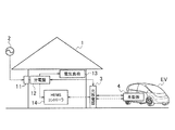
本発明の第1実施形態として示す充放電システムは、例えば図1に示すように構成される。この充放電システムは、商用電源2に接続された住宅1に、充放電器3が接続される。また、充放電システムは、充放電器3に電動車両(EV)が接続可能となっている。[First Embodiment]
The charging / discharging system shown as 1st Embodiment of this invention is comprised as shown, for example in FIG. In this charging / discharging system, a charger /
住宅1には、電力メータ11、分電盤12、電気負荷(住宅内機器)13、HEMS(ホームエネルギーマネジメントシステム)コントローラ14が設置されている。なお、住宅1は、太陽電池や燃料電池等を備えていてもよい。太陽電池や燃料電池等を備える場合、太陽電池や燃料電池等は、DC/DCコンバータやDC/ACコンバータを介して分電盤12に接続されている。
A
この充放電システムは、商用電源2からの電力を、電力メータ11、分電盤12を介して電気負荷13に供給する。また、充放電システムは、分電盤12と充放電器3との間で電力の授受が可能である。この分電盤12と充放電器3との間の電力の授受は、HEMSコントローラ14によって制御される。
This charging / discharging system supplies power from the
充放電器3は、DC/DCコンバータ、DC/ACコンバータ等を有している。充放電器3は、電動車両に対する充電動作及び放電動作を行う。充放電器3の充電動作は、分電盤12から供給された電力を、電動車両の充電に適した電力に変換して、電動車両に供給する。充放電器3の放電動作は、電動車両から供給された電力を、分電盤12に適した電力に変換して、分電盤12に供給する。
The charger /
充放電器3は、ケーブルを介して電動車両と着脱可能である。例えばケーブルには、電力線と通信線とが内蔵されている。充放電器3は、ケーブルを介して、電動車両との間で電力を授受する。同時に、充放電器3は、ケーブルを介して、電動車両との間で情報を授受することができる。なお、充放電器3は、電力線とは別個の信号線や無線技術等を利用して、電動車両との間で情報を授受してもよい。
The charger /
充放電器3は、HEMSコントローラ14と接続されている。充放電器3は、HEMSコントローラ14との間で情報を授受し、HEMSコントローラ14の制御に従って、電動車両に対する充電動作及び放電動作を行う。
The charger /
充放電器3は、通信手段、入力手段、記憶手段、提示手段を含む。通信手段は、電動車両の車載器(車載装置)4と接続されたときに情報の授受を行う。通信手段は、例えばケーブルに内蔵された通信線と接続された通信I/Fは無線I/F等である。入力手段は、各種の情報を入力する。この入力手段は、ユーザの操作を受け付けるボタン等が挙げられる。
The charger /
記憶手段は、入力手段及び通信手段により取得した情報を用いて、電動車両を特定する車両IDと、自己を特定する充放電器IDと、電動車両ごとの充電及び放電の履歴を示す履歴情報とを対応づけて記憶する。記憶手段は、内蔵ハードディスク装置等である。また、記憶手段は、充放電器3がアクセス可能な住宅1内のメモリであってもよい。
The storage means uses the information acquired by the input means and the communication means to identify a vehicle ID that identifies an electric vehicle, a charger / discharger ID that identifies itself, and history information that indicates a history of charging and discharging for each electric vehicle; Are stored in association with each other. The storage means is a built-in hard disk device or the like. The storage means may be a memory in the
提示手段は、記憶手段に記憶された履歴情報を、車両IDごとに車両利用者に提示する。この提示手段は、筐体表面に設置されたディスプレイや、スピーカ等である。 The presenting means presents the history information stored in the storage means to the vehicle user for each vehicle ID. The presenting means is a display or a speaker installed on the surface of the casing.
電動車両は、内蔵された車載バッテリに充電された電力を用いて走行する。電動車両は、車載バッテリに対する放充電を制御する車載器4が搭載されている。
The electric vehicle travels using electric power charged in a built-in on-board battery. The electric vehicle is equipped with a vehicle-mounted
車載器4は、通信手段、入力手段、記憶手段、提示手段を含む。通信手段は、充放電器3と接続されたときに情報の授受を行う。通信手段は、例えばケーブルに内蔵された通信線と接続された有線通信I/Fや、無線通信を行うための無線通信I/F等である。入力手段は、各種の情報を入力する。この入力手段は、ユーザの操作を受け付けるナビゲーション装置に備えられたボタン等が挙げられる。
The vehicle-mounted
記憶手段は、入力手段及び通信手段により取得した情報を用いて、車両(EV)を特定する車両IDと、当該電動車両に接続可能な充放電器3を特定する充放電器IDと、当該電動車両に対する充電及び放電の履歴を示す履歴情報とを対応づけて記憶する。記憶手段は、ナビゲーション装置等に備えられたハードディスク装置等である。
The storage means uses the information acquired by the input means and the communication means to identify the vehicle (EV), the charger / discharger ID that identifies the charger /
提示手段は、記憶手段に記憶された履歴情報を、車両IDと充放電を行った充放電器IDによって特定された充放電器3との組に対応づけて車両利用者に提示する。この提示手段は、ナビゲーション装置のディスプレイや、スピーカ等である。
The presenting means presents the history information stored in the storage means to the vehicle user in association with the pair of the vehicle ID and the charger /
このような充放電システムは、工程(1)〜(8)のような充電動作を行う。 Such a charge / discharge system performs a charging operation as in steps (1) to (8).
先ず(1)において、電動車両と充放電器3とがケーブルを介して接続される。
First, in (1), the electric vehicle and the charger /
次の(2)において、電動車両の充電を実施することを、充放電器3に入力する。充放電器3には、例えば充電を開始することを指示する操作ボタンが備えられている。ユーザが操作ボタンを操作することによって、充放電器3は、電動車両の充電を実施する。また、充放電器3は、タイマの設定によって電動車両の充電を実施してもよい。なお、充電の実施を充放電器3側で入力するとしたが、車載器4やユーザが携帯する端末機で入力してもよい。
In the next (2), the charging / discharging
次の(3)において、充放電器3は、車載器4との間で通信(通信手段)を行い、車載器4に充電の実施を通知する。
In the next (3), the charger /
次の(4)において、充放電器3は、電動車両の車載バッテリに充電を実施する。このとき、充放電器3は、分電盤12から商用電力が供給され、当該商用電力にDC/AC変換及びDC/DC変換等を行う。
In the next (4), the charger /
次の(5)において、充放電器3は、充電量を計測する。充放電器3は、充電時の電気料金単価をHEMSコントローラ14から取得する。充放電器3は、計測した充電量と取得した電気料金単価とを乗算し、今回の充電動作に要した充電コストを算出する。なお、充電コストの演算を充放電器3により行うとしたが、車載器4により行ってもよい。
In the next (5), the charger /
次の(6)において、充放電器3から車載器4に、充電日時、充放電器ID、充電量、電気料金単価、充電コストの情報を伝達する。
In the next (6), charging date / time, charging / discharging device ID, charging amount, unit price of electric charge, and charging cost are transmitted from the charging / discharging
次の(7)において、燃料費のカウンタに今回の充電コストを加算する。この工程は、車載器4、充放電器3、HEMSコントローラ14の何れかで行ってもよい。
In the next (7), the current charging cost is added to the fuel cost counter. This step may be performed by any of the on-
次の(8)において、車載器4、充放電器3、又は、HEMSコントローラ14によって、燃料費の積算額を提示する。
In the next (8), the on-
充放電システムは、工程(1)〜(8)のような放電動作を行う。 The charge / discharge system performs a discharge operation as in steps (1) to (8).
先ず(1)において、電動車両と充放電器3とがケーブルを介して接続される。
First, in (1), the electric vehicle and the charger /
次の(2)において、電動車両の放電を実施することを、充放電器3に入力する。充放電器3には、例えば放電を開始することを指示する操作ボタンが備えられている。ユーザが操作ボタンを操作することによって、充放電器3は、電動車両の放電を実施する。また、充放電器3は、タイマの設定によって電動車両の放電を実施してもよい。なお、放電の実施を充放電器3側で入力するとしたが、車載器4やユーザが携帯する端末機で入力してもよい。
In the next (2), the fact that the electric vehicle is discharged is input to the charger /
次の(3)において、充放電器3は、車載器4との間で通信(通信手段)を行い、車載器4に放電の実施を通知する。
In the next (3), the charger /
次の(4)において、充放電器3は、電動車両の車載バッテリから充放電器3に放電を実施する。このとき、充放電器3は、電動車両から直流電力が供給され、当該直流電力にDC/DC変換及びDC/AC変換等を行う。
In the next (4), the charger /
次の(5)において、充放電器3は、放電量を計測する。充放電器3は、放電時の電気料金単価をHEMSコントローラ14から取得する。充放電器3は、計測した放電量と取得した電気料金単価とを乗算し、今回の放電動作により得られた放電コストを算出する。なお、放電コストの演算を充放電器3により行うとしたが、車載器4により行ってもよい。
In the next (5), the charger /
次の(6)において、充放電器3から車載器4に、放電日時、充放電器ID、放電量、電気料金単価、放電コストの情報を伝達する。
In the next (6), information on the discharge date / time, the charger / discharger ID, the discharge amount, the unit price of electricity, and the discharge cost is transmitted from the charger /
次の(7)において、燃料費のカウンタに今回の放電コストを減算する。この工程は、車載器4、充放電器3、HEMSコントローラ14の何れかで行ってもよい。
In the next (7), the current discharge cost is subtracted from the fuel cost counter. This step may be performed by any of the on-
次の(8)において、車載器4、充放電器3、又は、HEMSコントローラ14によって、燃料費の積算額を提示する。
In the next (8), the on-
この充放電システムにおいて、充放電器3、車載器4の記憶手段には、例えば図2に示すような基本記憶テーブルが記憶されている。この基本記憶テーブルには、充放電日時、充放電器ID、充電量/放電量、電気料金単価、充電コスト/放電コスト、燃費量(積算値)が対応づけられている。この基本記憶テーブルにおいて、充電量、充電コストは正の値で表し、放電量、放電コストは負の値で表している。
In this charging / discharging system, for example, a basic storage table as shown in FIG. 2 is stored in the storage means of the charger /
この基本記憶テーブルは、所定の回数又は期間に亘る充放電動作の履歴情報を記憶していればよい。例えば、過去24回分の充放電動作の履歴であってもよく、過去6ヶ月の充放電動作の履歴であってもよい。 This basic storage table only needs to store history information of charge / discharge operations over a predetermined number of times or periods. For example, it may be a history of charge / discharge operations for the past 24 times, or a history of charge / discharge operations for the past 6 months.
このような基本記憶テーブルは、充放電器3、車載器4の記憶手段に記憶され、情報の提示時に、読み出される。したがって、この充放電システムは、車両IDと充放電器IDごとに、電動車両の充放電量と電気料金単価を管理することで充放電に要した費用のコストの見える化が可能となる。したがって、住宅1で使用する電力を有効に利用することを促すために、ユーザによって利用しやすくする環境を整備することができる。
Such a basic storage table is stored in the storage means of the charger /
この充放電システムは、電動車両の充放電量の単位量とCO2排出単位を管理することで充放電に要したCO2排出量の見える化が可能となる。このとき、単位充放電量に対するCO2排出量を示すCO2排出係数は、HEMSコントローラ14から取得する。This charge / discharge system makes it possible to visualize the CO 2 emission amount required for charge / discharge by managing the unit amount of the charge / discharge amount of the electric vehicle and the CO 2 emission unit. At this time, CO 2 emission coefficient indicating the CO 2 emissions per unit discharge amount is obtained from the
また、この充放電システムにおいて、車載器4は、複数の充放電器3で充電することもできる。例えば自宅の充放電器3により充放電することがあり、出先の充放電器3により充電を行う場合がある。この場合であっても、車載器4は、接続された充放電器3の充放電器IDを取得する。車載器4は、取得した充放電器IDに関連付けて、充放電履歴を保持する。車載器4は、予め初期設定された充放電器3に接続した場合に、当該充放電器3に過去の充放電履歴を送信する。この初期設定された充放電器は、例えば自宅等、電動車両の所有者が主に使用する充放電器3である。これにより、車載器4は、自宅以外の充放電器3により充電した場合であっても、主に使用する充放電器3ではないことを認識する。そして車載器4は、当該自宅以外の充放電器3から、充放電器ID、充電量、電気料金単価を取得できる。これにより、充放電システムは、住宅1以外で充電した充放電履歴を含めて住宅1の充放電器3及びHEMSコントローラ14に伝達する。これにより、充放電システムは、住宅1以外で充電した充放電履歴を含めて充放電履歴を提示できる。
Moreover, in this charging / discharging system, the vehicle-mounted
更に、この充放電システムは、複数の充放電器3による電動車両の充放電履歴(充放電コストやCO2排出量)を提示してもよく、特定(住宅1)の充放電器3による電動車両の充放電履歴を提示してもよい。Furthermore, this charging / discharging system may present the charging / discharging history (charging / discharging cost and CO 2 emission amount) of the electric vehicle by the plurality of charging / discharging
[第2実施形態]
つぎに、本発明の第2実施形態として示す充放電システムについて説明する。なお、上述した実施形態と同様の部分については同一符号を付することによりその詳細な説明を省略する。[Second Embodiment]
Next, a charge / discharge system shown as a second embodiment of the present invention will be described. In addition, about the part similar to embodiment mentioned above, the detailed description is abbreviate | omitted by attaching | subjecting the same code | symbol.
第2実施形態として示す充放電システムは、充放電器3が設置された地域を含む充放電履歴を提示するものである。この充放電システムは、図3に示すように、複数の店舗20A,20B,20CがNWサービスシステム30に接続されている。NWサービスシステム30は、店舗20A,20B,20Cに設置された多数の充電器21の情報を収集する。このNWサービスシステム30は、インターネット等を介して充電器21から情報を収集する情報収集サーバ(エネルギーマネジメントセンター)を含む。この情報収集サーバは、多数の充電器21と、多数の電動車両の車載器4との間で通信が可能な通信機能を備えている。
The charging / discharging system shown as 2nd Embodiment presents the charging / discharging log | history containing the area where the charger /
充電器21は、当該充電器21を特定する充放電器IDと、当該充電器21が設置された地域を特定する地域IDとが記憶されている。この地域IDは、地図上の特定の地域でなくてもよい。例えば、地域IDは、店舗に設けられた複数の充電器21を含むグループを特定するグループIDであってもよい。
The
NWサービスシステム30は、多数の充電器21から、地域ID、充放電器ID、電気料金単価を取得する。これにより、NWサービスシステム30は、図4に示すような記憶テーブルを作成する。この記憶テーブルは、グループID(又は地域ID)、充放電器ID、電気料金単価が対応づけられている。地域の充電コスト(電気料金単価)は、地域ごとに異なる。なお、この充放電システムにおいて、売電等の目的で充電器21に放電可能な場合には、放電コストも取得できる。
The
このような充放電システムにおいて、電動車両の車載器4は、入力手段又は通信手段によって、電動車両が充放電を行った充電器21が設置された地域を特定する地域ID(又はグループID)及び当該地域の充電コストを取得する。第2実施形態において、車載器4は、通信手段によってNWサービスシステム30に蓄積された図4の記憶テーブルを取得する。また、車載器4は、ユーザの操作に応じて、入力手段によって図4の記憶テーブルを入力してもよい。
In such a charging / discharging system, the vehicle-mounted
車載器4の記憶手段は、地域ID(又はグループID)及び充放電コストを、充放電を行った充電器21を示す充放電器IDに対応づけて記憶する。
The storage means of the vehicle-mounted
このようなNWサービスシステム30は、電力需要量と電力供給量にあわせて、各地域、グループの電気料金単価を調整する。例えば、店舗20Aの充電器21の充放電コストは20円/kWhである。他の店舗20Bの充電器21の充放電コストは10円/kWhである。他の店舗20Cの充電器21の充放電コストは30円/kWhである。車載器4は、履歴情報としての地域IDによって特定される地域及び充放電コストと、当該地域によって対応づけられた充電器21及び車両IDの組とを対応づけて提示する。したがって、充放電システムによれば、複数の地域のうち電気料金単価が安い地域の充電器21によって充放電を実施できる情報を提示できる。
Such an
以上のように、第2実施形態として示した充放電システムによれば、電動車両の充放電場所を管理し、単価の異なる充放電コストを正確に区別して見える化することで、エリアエネルギーマネージメントへの活用が可能となる。 As described above, according to the charging / discharging system shown as the second embodiment, the charging / discharging location of the electric vehicle is managed, and the charging / discharging costs with different unit prices are accurately distinguished and visualized, thereby enabling area energy management. Can be used.
なお、地域ID(グループID)によって複数の充放電器IDを管理するとしたが、グループIDで車両IDを管理することにしてもよい。例えば、タクシー会社のグループIDで車両IDを管理する。これにより、自社の燃料費用を一括して把握することができる。 In addition, although several charger / discharger ID was managed by area ID (group ID), you may decide to manage vehicle ID by group ID. For example, the vehicle ID is managed by the group ID of the taxi company. Thereby, it is possible to grasp the fuel cost of the company in a lump.
また、グループIDごとの電力料金の提示方法は、電力料金が安い順に提示してもよいし、電動車両の現在地からの距離の近い順に提示してもよい。 Moreover, the presentation method of the electric power charge for each group ID may be presented in the order from the lowest electric power charge, or may be presented in the order of the distance from the current location of the electric vehicle.
[第3実施形態]
つぎに、本発明の第3実施形態として示す充放電システムについて説明する。なお、上述した実施形態と同様の部分については同一符号を付することによりその詳細な説明を省略する。[Third Embodiment]
Next, a charge / discharge system shown as the third embodiment of the present invention will be described. In addition, about the part similar to embodiment mentioned above, the detailed description is abbreviate | omitted by attaching | subjecting the same code | symbol.
第3実施形態として示す充放電システムは、充放電器3又は車載器4によって、不正に充放電器3が使用されることを抑制するものである。
The charging / discharging system shown as 3rd Embodiment suppresses that the charger /
この充放電システムは、図5に示すように、電動車両が充放電器3に初回に接続された時に、電動車両が、自身のニックネーム:○○△△の電動車両と、車両ID:YYYを充放電器3に送信する。充放電器3は、ニックネーム:○○△△の電動車両及び車両ID:YYYをHEMSコントローラ14に転送する。HEMSコントローラ14は、当該電動車両を充放電器3によって充放電を行う電動車両として登録するかの確認を行う。このとき、HEMSコントローラ14は、例えば住宅1内のディスプレイに「○○△△の電動車両(YYY)を登録しますか?」というメッセージと、YES、NOというボタンを表示させる。その結果、YESボタンが操作された場合には、HEMSコントローラ14及び充放電器3は、当該電動車両が充放電器3による充放電を行うことができることを登録する。
As shown in FIG. 5, when the electric vehicle is connected to the charger /
初回登録された上で、図6に示すように、電動車両が充放電器3に接続されると(ステップS1)、充放電器3は、電動車両の車両IDを取得する(ステップS2)。このとき、車載器4の通信手段によって、電動車両が充放電器3と接続された場合に、記憶手段に記憶された車両IDを充放電器3に送信する。充放電器3の通信手段は、電動車両と接続された場合に、当該電動車両から車両IDを受信する。
After the initial registration, as shown in FIG. 6, when the electric vehicle is connected to the charger / discharger 3 (step S1), the charger /
充放電器3は、ステップS3において、ステップS2にて取得した車両IDが、登録済みの車両IDか否かを判定する。車両IDが登録されている場合には、充放電器3は、ステップS4において、充放電動作を許可する。
In step S3, the charger /
一方、車両IDが登録されていない場合には、HEMSコントローラ14は、車両IDを登録するか否かを判定する。HEMSコントローラ14は、ユーザの操作に応じて車両IDが登録された場合には、当該車両IDを充放電器3に登録する。これにより、充放電器3は、ステップS4にて充放電動作を許可する。一方、充放電器3は、車両IDが登録されない場合には、ステップS6において、充放電動作を禁止する。なお、充放電動作の許可及び禁止は、車載器4によって判定してもよく、充放電器3によって判定してもよい。
On the other hand, when the vehicle ID is not registered, the
以上のように、この充放電システムによれば、充放電器3によって、充放電器3の充放電動作を許可することができる電動車両か否かを識別する。これにより、充放電システムは、充電の可否を充放電器3が判断できるので、充電操作を簡易にすることができる。
As described above, according to the charging / discharging system, the charger /
また、この充放電システムによれば、車載器4自身によって、充放電器3の充放電動作が許可されるか否かを識別してもよい。これにより、充放電システムは、充電の可否を車載器4が判断できるので、充電操作を簡易にすることができる。
Moreover, according to this charging / discharging system, you may identify whether charging / discharging operation | movement of the charger /
なお、この実施形態では、電動車両について充電動作と放電動作の可否を一括して登録して管理する方式としたが、これに限らない。すなわち、電動車両ごとに充電動作の可否と放電動作の可否を分けて管理してもよく、充電動作のみ許可する、又は、放電動作のみ許可するという一方のみの管理であってもよい。 In this embodiment, the electric vehicle is registered and managed as to whether or not the charging operation and the discharging operation are possible. However, the present invention is not limited to this. That is, whether or not a charging operation is possible and whether or not a discharging operation is allowed may be managed separately for each electric vehicle, or only one management may be performed in which only a charging operation is permitted or only a discharging operation is permitted.
さらに、充放電器3に登録された車両IDをHEMSコントローラ14の画面で一覧表示し、選択した車両IDを削除する機能を持ってもよい。
Further, the vehicle ID registered in the charger /
また、電動車両が接続された充放電器3に対して車両IDを登録する方式としたが、1回の接続でグループ化された複数台の充放電器3に車両IDを登録する方式であってもよい。
Moreover, although it was set as the system which registers vehicle ID with respect to the charger /
更に、電動車両が接続された充放電器3に対して車両IDを登録する方式としたが、充放電器3にPCやスマートフォン等から一括で充放電を許可する車両IDを登録してもよい。
Furthermore, although it was set as the system which registers vehicle ID with respect to the charger /
更に、電動車両が接続された充放電器3に対して車両IDを登録する方式としたが、充放電器3にカード認証させることで車両IDを登録させる方式としてもよい。また、登録された車両IDは、一定期間、当該車両IDの電動車両が接続されない場合には削除するようにしてもよい。
Furthermore, although it was set as the system which registers vehicle ID with respect to the charger /
[第4実施形態]
つぎに、本発明の第4実施形態として示す充放電システムについて説明する。なお、上述した実施形態と同様の部分については同一符号を付することによりその詳細な説明を省略する。[Fourth Embodiment]
Next, a charge / discharge system shown as the fourth embodiment of the present invention will be described. In addition, about the part similar to embodiment mentioned above, the detailed description is abbreviate | omitted by attaching | subjecting the same code | symbol.
第4実施形態として示す充放電システムは、車載器4が、住宅1内の電気負荷13から送信され充放電器3を経由して供給された命令に従って、車両利用者の行動に応じた動作を開始させる。
In the charging / discharging system shown as the fourth embodiment, the vehicle-mounted
また、第4実施形態として示す充放電システムは、充放電器3の通信手段によって、電気負荷13から送信された命令を電動車両に送信すると共に、電動車両が充放電器3に接続されたことを電気負荷13に送信する。これにより、充放電システムは、当該命令に従って、車両利用者の行動に応じた動作を車載器4に開始させると共に、電動車両が接続されたことに応じて、車両利用者の行動に応じた動作を電気負荷13に開始させる。
Moreover, the charging / discharging system shown as 4th Embodiment transmitted the command transmitted from the
このような充放電システムは、予め充放電器3に登録された車両IDに対して、以下の動作を行う。
Such a charge / discharge system performs the following operations on the vehicle ID registered in the charger /
図7(a)に示すように、ユーザの外出時、先ず、(1)ユーザが、HEMSコントローラ14によって「在宅モード」を「外出モード」に切り替える。この在宅モードは、防犯機器によって外部侵入者を監視しない動作モードである。一方、外出モードは、カメラ装置や人感センサ、窓センサによって外部侵入者を監視し、必要に応じて光や音等によって警報動作を行う動作モードである。
As shown in FIG. 7A, when the user goes out, first, (1) the user switches the “home mode” to the “outing mode” by the
次に、(2)HEMSコントローラ14は、ユーザが外出することを示す情報を充放電器3を経由して車載器4に伝達する。なお、外出の通知は、HEMSコントローラ14により行うとしたが、ユーザが携帯するスマートフォン等から直接電動車両に通知してもよい。また、HEMSコントローラ14は、予め登録された充放電器IDの充放電器3に対して、上記の動作を行ってもよい。
Next, (2) the
次に、(3)充放電器3は、HEMSコントローラ14から住宅1内の居室空調機(エアコン)の稼働状況の情報(例えば温度)を得る。車載器4は、充放電器3を介して得た住宅1内の温度に合わせて、自動的に電動車両の車内を快適な温度に空調しておく。これにより、車載器4は、外出時に自動的に電動車両のエアコンをオンにできる。
Next, (3) the charger /
図7(b)に示すように、ユーザの帰宅時、(1)ユーザによって、電動車両の充電コネクタにケーブルが接続され、電動車両が充放電器3に接続される。
As shown in FIG. 7B, when the user returns home, (1) the user connects the cable to the charging connector of the electric vehicle, and the electric vehicle is connected to the charger /
次に(2)充放電器3は、電動車両の車両IDを取得し、当該車両IDが住宅1の住人であるユーザであることを認識する。充放電器3は、HEMSコントローラ14にユーザが帰宅したこと情報を伝達する。なお、HEMSコントローラ14への車両IDの登録は、上述した第3実施形態で説明した動作を行うことが望ましい。また、HEMSコントローラ14は、予め登録された車両IDに対して、上記した充放電動作の許可を行ってもよい。
Next, (2) the charger /
次に(3)HEMSコントローラ14は、電気負荷13の動作モードを「外出モード」から「在宅モード」に切り替える。これにより、電気負荷13としての居室の空調機や照明には、電源が投入される。
Next, (3) the
以上のように、この充放電システムによれば、住人の行動に合わせて、住宅1内から電動車両を制御できる。また、この充放電システムによれば、住人の行動に合わせて、電動車両から住宅1内の電気負荷13を制御できる。これにより、電動車両を利用することによる快適度が高まる。
As mentioned above, according to this charging / discharging system, an electric vehicle can be controlled from the
[第5実施形態]
つぎに、本発明の第5実施形態として示す充放電システムについて説明する。なお、上述した実施形態と同様の部分については同一符号を付することによりその詳細な説明を省略する。[Fifth Embodiment]
Next, a charge / discharge system shown as the fifth embodiment of the present invention will be described. In addition, about the part similar to embodiment mentioned above, the detailed description is abbreviate | omitted by attaching | subjecting the same code | symbol.
第5実施形態として示す充放電システムは、住宅1で充電した電力量以上を住宅1内で放電させないものである。この充放電システムは、住宅1以外の充放電器によって充電した電力を、住宅1に放電して電気負荷13によって消費させない、又は、住宅1から外部に売電させないものである。
The charge / discharge system shown as the fifth embodiment does not discharge more than the amount of power charged in the
このために、充放電システムは、図8に示すように、電動車両に、充電場所(充放電器ID)と充電量とを対応づけた記憶テーブルを記憶させる。車載器4の通信手段は、電動車両が充放電器3と接続された場合に、記憶手段に記憶された車両IDを充放電器3に送信する。車載器4は、接続された充放電器3により以前に電動車両に充電された充電量を超えない範囲で、当該電動車両から放電を行う。
For this purpose, as shown in FIG. 8, the charging / discharging system causes the electric vehicle to store a storage table in which a charging place (charge / discharger ID) and a charge amount are associated with each other. The communication means of the vehicle-mounted
この充放電システムは、車載器4ではなく、充放電器3によって、電動車両の放電を制御してもよい。充放電器3は、充電場所(充放電器ID)と充電量とを対応づけた記憶テーブルを記憶させる。充放電器3は、通信手段が電動車両と接続された場合に、当該電動車両から車両IDを受信する。充放電器3は、以前に電動車両に充電された充電量を超えない範囲で、当該電動車両から放電を行わせる。これにより、充放電器3は、以前に電動車両に充電された充電量を超えない範囲で、住宅1に放電電力を供給する。
In this charging / discharging system, the discharging of the electric vehicle may be controlled not by the vehicle-mounted
このような充放電システムは、例えば、以下の動作を行う。この動作では、記憶テーブルが充放電器3に記憶され、充放電器3が電動車両の放電を管理する。
Such a charge / discharge system performs the following operations, for example. In this operation, the storage table is stored in the charger /
この充放電システムは、電動車両への充電時において、(1)電動車両と充放電器3とをケーブルによって接続する。これにより、車載器4は、充放電器3と通信可能となる。次の(2)において、充放電器3から電動車両のバッテリへ充電を行う。次の(3)において、充放電器3は、電動車両の車載器4に記憶された充放電日時、車両ID、充電量を取得する。次の(4)において、充放電器3は、記憶しておいた充放電量の積算値に今回の充電量を加算する。
In this charging / discharging system, at the time of charging an electric vehicle, (1) the electric vehicle and the charger /
一方、電動車両におけるバッテリ電力の放電時において、(1)電動車両と充放電器3とをケーブルによって接続する。これにより、車載器4は、充放電器3と通信可能となる。次の(2)において、充放電器3は車載器4に記憶された電動車両の車両IDを取得し、当該車両IDに対応して記憶しておいた充放電量の積算値を呼び出す。次の(3)において、充放電器3は、充放電量の積算値を上限として、電動車両のバッテリから放電を行う。充放電器3は、電動車両におけるバッテリの放電が完了すると、次の(4)において、充放電器3は、充放電量の積算値から今回の放電量を減算する。充放電器3は、充放電量の積算値が「0」となった場合に、電動車両の放電を停止する。
On the other hand, when the battery power is discharged in the electric vehicle, (1) the electric vehicle and the charger /
このような充放電システムの充放電器3は、例えば図9に示すような処理を行うこともできる。
The charger /
先ずステップS11において、充放電器3は、電動車両と接続されたことを検出する。これにより、車載器4は、充放電器3と通信可能となる。
First, in step S11, the charger /
次のステップS12において、充放電器3は、車載器4に記憶された電動車両の車両IDを取得する。
In the next step S <b> 12, the charger /
次のステップS13において、充放電器3は、住宅1が商用電源2から電力供給が停止している停電中か否かを判定する。このとき、HEMSコントローラ14は、商用電源2から分電盤12に電力供給が停止していることを検出する。充放電器3は、HEMSコントローラ14との通信によって、停電しているか否かを判定する。住宅1が停電していない通常運転をしている場合にはステップS14に処理を進め、住宅1が停電している場合にはステップS16に処理を進める。
In next step S <b> 13, the charger /
ステップS14において、充放電器3は、ステップS12にて取得した車両IDに対応した充放電の積算値Xを取得する。
In step S14, the charger /
次のステップS15において、充放電器3は、ステップS14にて取得した充放電の積算値Xを上限として、電動車両のバッテリから放電を開始する。
In the next step S15, the charger /
一方、住宅1が停電している時には、ステップS16において、充放電器3は、ステップS12にて取得した車両IDに対応する電動車両の電池残量を上限として、電動車両のバッテリから放電を開始する。
On the other hand, when the
充放電器3は、例えば、図10のような記憶テーブルを記憶している。充放電器3は、電動車両が接続される度に、車載器4から車両IDを取得する。そして、充放電器3は、電動車両に対する充電又は放電が完了する度に、電動車両のバッテリに対する充電量又は放電量を記憶する。充放電器3は、充電量を正の値で記憶し、放電量を負の値で記憶して、記憶テーブルを更新する。
The charger /
車載器4は、ケーブルによって充放電器3に接続された時に、電動車両の走行により消費された放電量をの情報充放電器3に供給する。これにより、充放電器3は、電動車両におけるバッテリの現在の電池残量を認識できる。
The vehicle-mounted
例えば図10に示すように、記憶テーブルには、車両IDがXXXである電動車両のバッテリに対する充電量の積算値が25[kWh]であることが登録されている。したがって、充放電器3は、当該電動車両のバッテリから放電可能な電力量の上限はとして25[kWh]を認識できる。これにより、充放電器3は、当該上限まで、電動車両のバッテリから電力を放電して、住宅1に供給できる。
For example, as shown in FIG. 10, it is registered in the storage table that the integrated value of the charge amount with respect to the battery of the electric vehicle whose vehicle ID is XXX is 25 [kWh]. Therefore, the charger /
なお、電動車両におけるバッテリの充電量を積算していくことで、放電可能量が無制限に大きくなる可能性がある。これに対し、充放電器3は、充放電の積算値の上限を、電動車両におけるバッテリの最大充電量としてもよい。また、充放電器3は、住宅1の停電時において充放電量の積算値が負となることを防ぐため、住宅1の停電中において放電量のカウントを停止してもよい。
In addition, there is a possibility that the dischargeable amount may increase without limitation by accumulating the charge amount of the battery in the electric vehicle. On the other hand, the charger /
以上のように、この充放電システムによれば、充放電器3又は車載器4によって、特定の充放電器3によって電動車両のバッテリに充電した電力量のみを放電させ、充放電器3から住宅1に放電を可能とする。したがって、この充放電システムによれば、電動車両の所有者の家庭である住宅1で充電した電力量以上を住宅1に向けて放電させない。これにより、充放電システムによれば、住宅1以外で充電した電動車両のバッテリ電力を住宅1で使用したり売電したりする電力の不正使用を防止できる。
As described above, according to this charging / discharging system, only the amount of power charged in the battery of the electric vehicle by the specific charger /
また、この充放電システムによれば、住宅1が停電している場合には、電動車両の充電残量だけ放電できる。これにより、充放電システムによれば、住宅1が停電した緊急時に限り、住宅1以外で充電された電力を住宅1に供給するよう電動車両の電力の使用を許可できる。
Moreover, according to this charging / discharging system, when the
[第6実施形態]
つぎに、本発明の第6実施形態として示す充放電システムについて説明する。なお、上述した実施形態と同様の部分については同一符号を付することによりその詳細な説明を省略する。[Sixth Embodiment]
Next, a charge / discharge system shown as the sixth embodiment of the present invention will be described. In addition, about the part similar to embodiment mentioned above, the detailed description is abbreviate | omitted by attaching | subjecting the same code | symbol.
第6実施形態として示す充放電システムは、充放電器3の位置と電動車両の目的地とに基づいて電動車両におけるバッテリの充電量を制御するものである。例えば図11に示すように、例えばマンション等の集合住宅1Aにおいて、充放電器3の台数に対して、当該充放電器3に接続される電動車両の台数が多い場合がある。この場合、充放電器3は、単位時間あたりの充放電量が限られているために、すべての電動車両のバッテリを走行前に満充電できない可能性がある。このため、充放電器3は、充放電器3の位置と電動車両の目的地とに基づいて、各電動車両の充電量を制御する。
The charging / discharging system shown as 6th Embodiment controls the charge amount of the battery in an electric vehicle based on the position of the charger /
充放電器3は、例えば図12(a)に示すように、自己の充放電器IDと緯度情報及び経度情報とを対応づけて、充電器位置情報を記憶している。また、充放電器3は、図12(b)に示すように、車両IDに対応づけて目的地情報としての緯度情報及び経度情報を記憶する。この目的地情報は、ケーブルを介して充放電器3が車載器4と接続された時に、車両IDと共に車載器4から充放電器3に送信される。
For example, as shown in FIG. 12A, the charger /
このような充放電システムは、例えば、以下の動作を行う。この動作では、記憶テーブルが充放電器3に記憶され、充放電器3が電動車両の放電を管理する場合について説明する。
Such a charge / discharge system performs the following operations, for example. In this operation, a case where the storage table is stored in the charger /
この充放電システムは、電動車両におけるバッテリへの充電時において、(1)電動車両と充放電器3とがケーブルを介して接続される。次の(2)において、充放電器3は、車載器4から車両IDを取得すると共に、車載器4から電動車両の目的地情報としての目的地の緯度及び経度を取得する。次の(3)において、充放電器3は、目的地の緯度、経度、自身の緯度、経度に基づいて電動車両の走行距離を算出する。充放電器3は、電動車両が走行距離を走行するために最低限必要な充電量を求める。次の(4)において、充放電器3は、(3)にて求めた充電量を下回らないように充電を行う。
In this charging / discharging system, at the time of charging a battery in an electric vehicle, (1) the electric vehicle and the charger /
充放電システムは、例えば非常時において、接続されている電動車両のバッテリから電力を放電してもよい。この電動車両におけるバッテリの放電時には、充放電器3は、上述した充電時の(1)〜(3)を行って、算出した走行距離を電動車両が走行するために最低限必要な充電量を求める。充放電器3は、求めた充電量を下回らないように電動車両におけるバッテリから放電を行う。
The charge / discharge system may discharge electric power from a battery of a connected electric vehicle, for example, in an emergency. At the time of discharging the battery in the electric vehicle, the charger /
なお、上述した実施形態は、充放電器3によって電動車両におけるバッテリの充放電量を設定しているが、車載器4によって、電動車両の現在位置情報と目的地情報とに基づいて走行距離を算出して、最低限必要な充電量、放電量を求めてもよい。
In the above-described embodiment, the charging / discharging amount of the battery in the electric vehicle is set by the charger /
以上のように、この充放電システムによれば、1台の充放電器3に対して複数台の電動車両におけるバッテリの充電を行う必要がある場合であっても、各電動車両におけるバッテリに最低限必要な充電量を確保できる。
As described above, according to this charging / discharging system, even when it is necessary to charge a battery in a plurality of electric vehicles with respect to one charger /
また、電動車両が配送車の場合、充放電器3又は車載器4は、配送計画に基づいて配送ルートを決定し、当該配送ルートを走行するために必要なバッテリの充電量を求めてもよい。これにより、充放電システムは、複数台の電動車両におけるバッテリを効率的に充電することができる。
When the electric vehicle is a delivery vehicle, the charger /
なお、走行距離の算出には、充放電器3や電動車両の現在位置、目的地情報についての緯度、経度情報を使用するとしたが、ルート番号からの距離としてもよい。
[第7実施形態]The travel distance is calculated using the current position of the charger /
[Seventh Embodiment]
つぎに、本発明の第7実施形態として示す充放電システムについて説明する。なお、上述した実施形態と同様の部分については同一符号を付することによりその詳細な説明を省略する。 Next, a charge / discharge system shown as the seventh embodiment of the present invention will be described. In addition, about the part similar to embodiment mentioned above, the detailed description is abbreviate | omitted by attaching | subjecting the same code | symbol.
第7実施形態として示す充放電システムは、第1実施形態に示したように電動車両のバッテリに対する充電及び放電の履歴を示す履歴情報に加えて他の情報も提示して、情報の見える化を実現するものである。充放電システムは、例えば図13に示すように、HEMSコントローラ14がインターネット等のネットワークNWを介して住宅1外のHEMSサーバ5と接続して、電動車両の平均燃費を提示して、見える化を実現するものである。
The charging / discharging system shown as the seventh embodiment presents other information in addition to the history information indicating the history of charging and discharging the battery of the electric vehicle as shown in the first embodiment, and makes the information visible. It is realized. In the charge / discharge system, for example, as shown in FIG. 13, the
このような充放電システムは、例えば、以下の動作を行う。 Such a charge / discharge system performs the following operations, for example.
この充放電システムは、電動車両におけるバッテリへの充電時において、先ず、(1)電動車両と充放電器3とがケーブルを介して接続される。
In this charging / discharging system, at the time of charging a battery in an electric vehicle, first, (1) the electric vehicle and the charger /
次の(2)において、充放電器3は、車載器4から、車両ID、電動車両の走行距離及び残バッテリー量(充電残量)を取得する。なお、充放電器3は、車載器4から電動車両の走行に使用した電力量を取得してもよい。
In the next (2), the charger /
次の(3)において、充放電器3は、電動車両の走行距離及び使用電力量から燃費平均値を計算する。充放電器3は、計算した燃費平均値を、例えばデータ取得日時ごとにHEMSコントローラ14に送信する。これにより、HEMSコントローラ14は、電動車両における燃費平均値データを蓄積できる。
In the next (3), the charger /
HEMSコントローラ14には、例えば図14に示すような記憶テーブルが作成される。この記憶テーブルは、充放電器3からのデータ取得日時、車両ID、電動車両の走行による放電量、走行距離、燃費平均値が含まれる。なお、燃費平均値の計算は、充放電器3に代わってHEMSコントローラ14によって行ってもよい。
For example, a storage table as shown in FIG. 14 is created in the
HEMSコントローラ14は、住宅1内の図示しない表示画面上で、電動車両の燃費平均値の推移を提示することにより、見える化を実現する。なお、燃費平均値の表示は、充放電器3の表示画面や、電動車両のカーナビゲーション等の車載器4や、ユーザが所持するスマートフォン上により表示してもよい。また、この燃費平均値は、図15に示すように、電動車両の利用日ごとにグラフ化してもよい。
The
次の(4)において、HEMSコントローラ14は、HEMSサーバ5に記憶テーブルに記憶されたデータを送信する。これによって、HEMSサーバ5には、電動車両のデータが蓄積される。なお、このデータの送信タイミングは、記憶テーブルが更新された時であってもよく、所定の期間ごとであってもよい。
In the next (4), the
HEMSサーバ5に蓄積されたデータは、特定の権限を有する通信機器によってダウンロードできるようにする。例えば、住宅1の住人が操作するパーソナルコンピュータがHEMSサーバ5にアクセスして、住宅1内のパーソナルコンピュータから平均燃費値を参照できるようにしてもよい。また、電動車両の整備会社に備えられたパーソナルコンピュータからHEMSサーバ5にアクセスして、電動車両の情報をダウンロードできるようにしてもよい。これにより、電動車両の整備会社のパーソナルコンピュータは、電動車両のメンテナンス時期を、住宅1内のパーソナルコンピュータに送信することができる。これによって、電動車両の使用状況に応じた最適なタイミングで電動車両のメンテナンスを実施することができる。
The data stored in the
以上のように、充放電システムによれば、HEMSコントローラ14によって電動車両の状況を提示し、見える化うを実現できる。更に、充放電システムによれば、電動車両についてのデータをHEMSサーバ5に送信することによって、住宅1の住人や他の者に電動車両の状況を提示して、見える化を実現することができる。
As described above, according to the charge / discharge system, the
なお、HEMSコントローラ14は、燃費に加え、電動車両におけるバッテリの充電に使用した電気料金単価を乗算して、電動車両のランニングコストを提示し、見える化を実現することができる。また、HEMSコントローラ14は、電動車両の燃費をガソリン車の燃費と比較してもよい。これによりHEMSコントローラ14は、イニシャルコスト及びランニングコストを含めた電動車両の投資回収を提示し、見える化を実現することができる。更に、燃費平均値の表示は、1台の電動車両のみとしてもよいし、複数台の電動車両の合算表示としてもよい。
In addition to the fuel consumption, the
なお、上述の実施の形態は本発明の一例である。このため、本発明は、上述の実施形態に限定されることはなく、この実施の形態以外であっても、本発明に係る技術的思想を逸脱しない範囲であれば、設計等に応じて種々の変更が可能であることは勿論である。 The above-described embodiment is an example of the present invention. For this reason, the present invention is not limited to the above-described embodiment, and various modifications can be made depending on the design and the like as long as the technical idea according to the present invention is not deviated from this embodiment. Of course, it is possible to change.
上述した充放電システムは、車載器4及び充放電器3のそれぞれが、相互に情報の授受を行う通信機能を有し、車載器4及び車載器4の双方又は一方が必要最低限の構成を有していればよい。すなわち、車載器4及び車載器4の双方又は一方が、各種の情報を入力する入力手段を有していればよい。また、車載器4及び車載器4の双方又は一方が、取得した情報を用いて、車両を特定する車両IDと、当該車両に接続可能な充放電器を特定する充放電器IDと、当該車両に対する充電及び放電の履歴を示す履歴情報とを対応づけて記憶する記憶手段を有していればよい。更に、車載器4及び車載器4の双方又は一方が、記憶手段に記憶された履歴情報を、車両IDと充放電を行った充放電器IDによって特定される充放電器との組に対応づけて車両利用者に提示する提示手段を備えていればよい。
The above-described charging / discharging system has a communication function in which each of the vehicle-mounted
特願2012-037199号(出願日:2012年2月23日)の全内容は、ここに援用される。 The entire contents of Japanese Patent Application No. 2012-037199 (filing date: February 23, 2012) are incorporated herein by reference.
本発明によれば、車両ID、充放電器ID、履歴情報とを対応づけて記憶し、履歴情報を、車両IDと充放電を行った充放電器IDによって特定される充放電器との組に対応づけて車両利用者に提示する。これにより、車両に要したコスト等を提示でき、ユーザによって車両を利用しやすくする環境を整備することができる。 According to the present invention, the vehicle ID, the charger / discharger ID, and the history information are stored in association with each other, and the history information is a set of the vehicle ID and the charger / discharger that is specified by the charger / discharger ID that has been charged / discharged. It is presented to the vehicle user in association with. Thereby, the cost required for the vehicle and the like can be presented, and an environment in which the user can easily use the vehicle can be maintained.
3 充放電器
4 車載器
14 HEMSコントローラ
21 充電器3 Charger /
Claims (6)
前記充放電器と接続されて情報の授受を行う通信手段と、
各種の情報を入力する入力手段と、
前記入力手段及び前記通信手段により取得した情報を用いて、車両を特定する車両IDと、当該車両に接続可能な充放電器を特定する充放電器IDと、当該車両に対する充電及び放電の履歴を示す履歴情報とを対応づけて記憶する記憶手段と、
前記記憶手段に記憶された履歴情報を、前記車両IDと前記充放電を行った充放電器IDによって特定される充放電器との組に対応づけて車両利用者に提示する提示手段と
を有し、
前記入力手段又は前記通信手段により、車両が充放電を行った充放電器が設置された地域を特定する地域ID及び当該地域の電力需要量と電力供給量にあわせて調整された充放電コストを取得し、
前記記憶手段は、前記地域ID及び前記充放電コストを、前記充放電器IDに対応づけて記憶し、
前記提示手段は、前記履歴情報としての前記地域IDによって特定される地域及び充放電コストと、当該地域によって対応づけられた充放電器ID及び前記車両IDの組とを対応づけて提示すること
を特徴とする車載装置。 An in-vehicle device mounted on a vehicle capable of charging / discharging electric power by a charger / discharger,
A communication means connected to the charger / discharger to exchange information;
An input means for inputting various information;
Using the information acquired by the input means and the communication means, a vehicle ID that identifies a vehicle, a charger / discharger ID that identifies a charger / discharger that can be connected to the vehicle, and a history of charging and discharging the vehicle. Storage means for storing history information in association with each other;
Presenting means for presenting history information stored in the storage means to a vehicle user in association with a set of the vehicle ID and a charger / discharger identified by the charger / discharger ID that has performed the charging / discharging. And
By the input means or the communication means, the area ID for specifying the area where the charger / discharger charged / discharged by the vehicle is installed, and the charge / discharge cost adjusted in accordance with the power demand and power supply amount of the area. Acquired,
The storage means stores the area ID and the charge / discharge cost in association with the charger / discharger ID,
The presenting means associates and presents a region and charge / discharge cost specified by the region ID as the history information, and a set of the charger / discharger ID and the vehicle ID associated with the region.
In-vehicle device characterized by
前記充放電器内において前記充放電器IDに対応して前記通信手段から送信された車両IDが登録されている場合には充放電動作が許可され、前記充放電器内において前記充放電器IDに対応して前記通信手段から送信された車両IDが登録されていない場合には充放電動作が禁止されること
を特徴とする請求項1に記載の車載装置。 When the vehicle is connected to the charger / discharger, the communication unit transmits the vehicle ID stored in the storage unit to the charger / discharger,
When the vehicle ID transmitted from the communication means corresponding to the charger / discharger ID is registered in the charger / discharger, a charge / discharge operation is permitted, and the charger / discharger ID is allowed in the charger / discharger. The in-vehicle device according to claim 1 , wherein the charging / discharging operation is prohibited when the vehicle ID transmitted from the communication unit is not registered correspondingly.
接続された充放電器により以前に車両に充電された充電量を超えない範囲で、当該車両から放電を行うこと
を特徴とする請求項1乃至請求項3の何れか一項に記載の車載装置。 When the vehicle is connected to the charger / discharger, the communication unit transmits the vehicle ID stored in the storage unit to the charger / discharger,
The in-vehicle device according to any one of claims 1 to 3 , wherein discharge is performed from the vehicle within a range that does not exceed a charge amount previously charged in the vehicle by the connected charger / discharger. .
自車両の現在位置と目的地とに基づいて、当該自車両に充電する充電量を設定することを特徴とする請求項1乃至請求項4の何れか一項に記載の車載装置。 The own vehicle is connected to the charger / discharger together with other vehicles,
The in-vehicle device according to any one of claims 1 to 4 , wherein a charge amount to be charged to the host vehicle is set based on a current position and a destination of the host vehicle.
前記車載装置及び前記充放電器のそれぞれが、相互に情報の授受を行う通信手段を有し、
前記車載装置及び前記充放電器の双方又は一方が、
各種の情報を入力する入力手段と、
前記入力手段及び前記通信手段により取得した情報を用いて、車両を特定する車両IDと、当該車両に接続可能な充放電器を特定する充放電器IDと、当該車両に対する充電及び放電の履歴を示す履歴情報とを対応づけて記憶する記憶手段と、
前記記憶手段に記憶された履歴情報を、前記車両IDと前記充放電を行った充放電器IDによって特定される充放電器との組に対応づけて車両利用者に提示する提示手段と
を備え、
前記入力手段又は前記通信手段により、車両が充放電を行った充放電器が設置された地域を特定する地域ID及び当該地域の電力需要量と電力供給量にあわせて調整された充放電コストを取得し、
前記記憶手段は、前記地域ID及び前記充放電コストを、前記充放電器IDに対応づけて記憶し、
前記提示手段は、前記履歴情報としての前記地域IDによって特定される地域及び充放電コストと、当該地域によって対応づけられた充放電器ID及び前記車両IDの組とを対応づけて提示すること
を特徴とする充放電システム。 A charging / discharging system having an in-vehicle device mounted on a vehicle and a charger / discharger that charges / discharges a battery of the vehicle,
Each of the in-vehicle device and the charger / discharger has a communication unit that exchanges information with each other,
Both or one of the in-vehicle device and the charger / discharger is
An input means for inputting various information;
Using the information acquired by the input means and the communication means, a vehicle ID that identifies a vehicle, a charger / discharger ID that identifies a charger / discharger that can be connected to the vehicle, and a history of charging and discharging the vehicle. Storage means for storing history information in association with each other;
Presenting means for presenting history information stored in the storage means to a vehicle user in association with a set of the vehicle ID and a charger / discharger identified by the charger / discharger ID that has performed the charging / discharging. ,
By the input means or the communication means, the area ID for specifying the area where the charger / discharger charged / discharged by the vehicle is installed, and the charge / discharge cost adjusted in accordance with the power demand and power supply amount of the area. Acquired,
The storage means stores the area ID and the charge / discharge cost in association with the charger / discharger ID,
The presenting means associates and presents a region and charge / discharge cost specified by the region ID as the history information, and a set of the charger / discharger ID and the vehicle ID associated with the region.
Charging / discharging system characterized by
Priority Applications (1)
| Application Number | Priority Date | Filing Date | Title |
|---|---|---|---|
| JP2014500920A JP6160928B2 (en) | 2012-02-23 | 2013-02-20 | In-vehicle device and charge / discharge system |
Applications Claiming Priority (4)
| Application Number | Priority Date | Filing Date | Title |
|---|---|---|---|
| JP2012037199 | 2012-02-23 | ||
| JP2012037199 | 2012-02-23 | ||
| JP2014500920A JP6160928B2 (en) | 2012-02-23 | 2013-02-20 | In-vehicle device and charge / discharge system |
| PCT/JP2013/000945 WO2013125217A1 (en) | 2012-02-23 | 2013-02-20 | Vehicle-mounted apparatus, charger/discharger, and charging/discharging system |
Publications (2)
| Publication Number | Publication Date |
|---|---|
| JPWO2013125217A1 JPWO2013125217A1 (en) | 2015-07-30 |
| JP6160928B2 true JP6160928B2 (en) | 2017-07-12 |
Family
ID=49005412
Family Applications (1)
| Application Number | Title | Priority Date | Filing Date |
|---|---|---|---|
| JP2014500920A Active JP6160928B2 (en) | 2012-02-23 | 2013-02-20 | In-vehicle device and charge / discharge system |
Country Status (4)
| Country | Link |
|---|---|
| US (1) | US9533594B2 (en) |
| EP (1) | EP2819263A4 (en) |
| JP (1) | JP6160928B2 (en) |
| WO (1) | WO2013125217A1 (en) |
Cited By (1)
| Publication number | Priority date | Publication date | Assignee | Title |
|---|---|---|---|---|
| KR102564791B1 (en) * | 2020-12-16 | 2023-08-14 | 주식회사 그리드위즈 | Method and System for Charging Electric Vehicle |
Families Citing this family (29)
| Publication number | Priority date | Publication date | Assignee | Title |
|---|---|---|---|---|
| JP6081817B2 (en) | 2013-02-26 | 2017-02-15 | 三菱重工業株式会社 | OBE and EV management system |
| JP6146324B2 (en) * | 2014-01-28 | 2017-06-14 | トヨタ自動車株式会社 | Charge / discharge system |
| JP2015154593A (en) * | 2014-02-14 | 2015-08-24 | ソニー株式会社 | Charge/discharge control device, battery pack, electronic apparatus, electric motor vehicle and charge/discharge control method |
| JP2015226329A (en) * | 2014-05-26 | 2015-12-14 | 三菱電機株式会社 | Charging/discharging system for electric automobile and authentication method for charging/discharging system for electric automobile |
| US9315108B2 (en) * | 2014-07-08 | 2016-04-19 | Toyota Jidosha Kabushiki Kaisha | Vehicle function determination |
| CN105071529A (en) * | 2015-07-16 | 2015-11-18 | 厦门金龙联合汽车工业有限公司 | Remote charging system based on Internet-of-vehicles |
| US9840156B2 (en) | 2015-08-14 | 2017-12-12 | Siemens Industry, Inc. | Automatically selecting charging routine for an electric vehicle by balancing utility and user considerations |
| US10427530B2 (en) * | 2015-11-13 | 2019-10-01 | Nio Usa, Inc. | Vehicle charge query and exchange system and method of use |
| US10753761B2 (en) | 2015-11-13 | 2020-08-25 | Nio Usa, Inc. | Universal battery and modular power system |
| US10252631B2 (en) | 2015-11-13 | 2019-04-09 | Nio Usa, Inc. | Communications between vehicle and charging system |
| CN105870982A (en) * | 2015-11-20 | 2016-08-17 | 乐视致新电子科技(天津)有限公司 | Intelligent charging method and system and intelligent charging pile |
| CN105857097A (en) * | 2015-11-20 | 2016-08-17 | 乐视致新电子科技(天津)有限公司 | Intelligent charging method and system and intelligent charging pile |
| WO2018061857A1 (en) | 2016-09-30 | 2018-04-05 | 日本電気株式会社 | Charging system, charging controller, charger, information device, charging method, and recording medium |
| US10699305B2 (en) * | 2016-11-21 | 2020-06-30 | Nio Usa, Inc. | Smart refill assistant for electric vehicles |
| CN107499151A (en) * | 2017-07-25 | 2017-12-22 | 东软集团股份有限公司 | A kind of electrically-charging equipment communication controler and charge control method |
| CN107623355A (en) * | 2017-10-12 | 2018-01-23 | 科世达(上海)管理有限公司 | A kind of configuration system, manager and the method for charging station power |
| EP3682527A4 (en) * | 2017-10-13 | 2021-11-10 | The Governing Council of the University of Toronto | On-board bidirectional ac fast charger for electric vehicles |
| JP2019092279A (en) * | 2017-11-14 | 2019-06-13 | トヨタ自動車株式会社 | Vehicle and power facility |
| JP7013864B2 (en) * | 2017-12-28 | 2022-02-01 | トヨタ自動車株式会社 | automobile |
| CN110535157B (en) * | 2018-05-24 | 2021-12-07 | 三菱电机(中国)有限公司 | Discharge control device and discharge control method for electric vehicle |
| JP2021192128A (en) * | 2018-06-18 | 2021-12-16 | 本田技研工業株式会社 | In-vehicle device and running cost calculation system |
| JP6745316B2 (en) * | 2018-09-28 | 2020-08-26 | 本田技研工業株式会社 | Vehicle information display device |
| JP7347309B2 (en) * | 2020-04-03 | 2023-09-20 | トヨタ自動車株式会社 | Information processing device, information processing method, and information processing program |
| DE102020213061A1 (en) * | 2020-10-15 | 2022-04-21 | Volkswagen Aktiengesellschaft | Method for authentication and release of a charging process of an electric or hybrid vehicle at a charging station, charging station and electric or hybrid vehicle |
| JP2022108595A (en) * | 2021-01-13 | 2022-07-26 | トヨタ自動車株式会社 | Information processing device and program |
| JP2022116971A (en) * | 2021-01-29 | 2022-08-10 | トヨタ自動車株式会社 | Electric power system |
| JP7389783B2 (en) * | 2021-11-17 | 2023-11-30 | 本田技研工業株式会社 | Power supply management system and power supply management device |
| WO2024024251A1 (en) * | 2022-07-25 | 2024-02-01 | パナソニックIpマネジメント株式会社 | Emission amount management device, charging device, and emission amount management method |
| DE102022120573A1 (en) * | 2022-08-16 | 2024-02-22 | Bayerische Motoren Werke Aktiengesellschaft | Charging an electric vehicle battery |
Family Cites Families (17)
| Publication number | Priority date | Publication date | Assignee | Title |
|---|---|---|---|---|
| JP4366382B2 (en) * | 2006-08-02 | 2009-11-18 | 株式会社東海理化電機製作所 | Charging system |
| JP2008054439A (en) * | 2006-08-25 | 2008-03-06 | Toyota Motor Corp | Power system |
| US7750640B2 (en) * | 2006-12-27 | 2010-07-06 | Panasonic Ev Energy Co., Ltd. | Electromotive force computing device and state of charge estimating device |
| JP2009060727A (en) * | 2007-08-31 | 2009-03-19 | Toyota Motor Corp | Electric vehicle |
| JP4466728B2 (en) | 2007-12-03 | 2010-05-26 | トヨタ自動車株式会社 | Electric vehicle charging system |
| JP4713623B2 (en) * | 2008-09-25 | 2011-06-29 | 株式会社日立製作所 | Charge / discharge management device |
| JP2010268576A (en) | 2009-05-13 | 2010-11-25 | Toyota Motor Corp | Power supply distribution control apparatus |
| WO2011007573A1 (en) | 2009-07-15 | 2011-01-20 | パナソニック株式会社 | Power control system, method, device and program |
| JP2011083085A (en) * | 2009-10-05 | 2011-04-21 | Panasonic Electric Works Co Ltd | Electric power management system |
| JP5304673B2 (en) * | 2010-02-02 | 2013-10-02 | 株式会社デンソー | Navigation device |
| US8232765B2 (en) * | 2010-03-13 | 2012-07-31 | James A Billmaier | Automatic and dynamic home electricity load balancing for the purpose of EV charging |
| JP2011211880A (en) * | 2010-03-31 | 2011-10-20 | Motion:Kk | In-vehicle mount type battery charging system, managing server, managing server control method, and program |
| JP5601008B2 (en) * | 2010-04-14 | 2014-10-08 | 日産自動車株式会社 | Information providing apparatus and information providing method |
| JP5678258B2 (en) * | 2010-04-15 | 2015-02-25 | パナソニックIpマネジメント株式会社 | CHARGING DEVICE CONTROL METHOD, CONTROL DEVICE, AND ITS PROGRAM |
| JP5494270B2 (en) * | 2010-06-17 | 2014-05-14 | 日産自動車株式会社 | Information providing apparatus and information providing method |
| JP5591020B2 (en) | 2010-08-11 | 2014-09-17 | 三菱重工業株式会社 | Air conditioner |
| JP5071545B2 (en) * | 2010-10-06 | 2012-11-14 | 株式会社デンソー | Electricity supply and demand system |
-
2013
- 2013-02-20 EP EP13752199.3A patent/EP2819263A4/en not_active Withdrawn
- 2013-02-20 US US14/380,326 patent/US9533594B2/en active Active
- 2013-02-20 WO PCT/JP2013/000945 patent/WO2013125217A1/en active Application Filing
- 2013-02-20 JP JP2014500920A patent/JP6160928B2/en active Active
Cited By (1)
| Publication number | Priority date | Publication date | Assignee | Title |
|---|---|---|---|---|
| KR102564791B1 (en) * | 2020-12-16 | 2023-08-14 | 주식회사 그리드위즈 | Method and System for Charging Electric Vehicle |
Also Published As
| Publication number | Publication date |
|---|---|
| WO2013125217A1 (en) | 2013-08-29 |
| EP2819263A1 (en) | 2014-12-31 |
| EP2819263A4 (en) | 2016-08-17 |
| JPWO2013125217A1 (en) | 2015-07-30 |
| US20150061592A1 (en) | 2015-03-05 |
| US9533594B2 (en) | 2017-01-03 |
Similar Documents
| Publication | Publication Date | Title |
|---|---|---|
| JP6160928B2 (en) | In-vehicle device and charge / discharge system | |
| US9428067B2 (en) | Vehicle running management system under renewable energy | |
| TWI486909B (en) | Apparatus, method and article for providing vehicle diagnostic data | |
| CN103891088B (en) | For providing device, the method and article of the information related with the availability of the electrical energy storage at electrical energy storage collection, charging and dispenser | |
| JP5440158B2 (en) | Battery charging method and charging system | |
| JP5596789B2 (en) | Method and apparatus for managing stored energy in a vehicle powered by a battery | |
| WO2013031963A1 (en) | Charge/discharge assist device | |
| JP7264032B2 (en) | Server and power management system | |
| JP2010022099A (en) | Parking system | |
| JP2011055589A (en) | Power supply system | |
| CN102164773A (en) | System and method for operating an electric vehicle | |
| JP2012085511A (en) | Vehicle charging system having charging efficiency control and providing adaptability charging service | |
| JP5376044B2 (en) | Charging station management device | |
| JP2014039389A (en) | Renewable energy storing/charging management system | |
| CN105210108A (en) | Apparatus, method and article for providing information regarding a vehicle via a mobile device | |
| JP2013025432A (en) | Device for providing information on environmental load reduction | |
| JP5501638B2 (en) | Charger | |
| JP2020054070A (en) | Power control system | |
| JP7040614B2 (en) | Vehicle management system, vehicle management computer, and vehicle management method | |
| JP6224205B2 (en) | Travel management system with renewable energy | |
| JP7484872B2 (en) | Power system, vehicle and information processing device | |
| US20230013438A1 (en) | Electric power management system, electric power management server, and electric power management method | |
| JP2022037662A (en) | Vehicle management system | |
| JP2024074620A (en) | POWER STORAGE DEVICE MANAGEMENT METHOD, VEHICLE CONTROL DEVICE, AND VEHICLE | |
| JP2022147843A (en) | charging management system |
Legal Events
| Date | Code | Title | Description |
|---|---|---|---|
| A621 | Written request for application examination |
Free format text: JAPANESE INTERMEDIATE CODE: A621 Effective date: 20160112 |
|
| A131 | Notification of reasons for refusal |
Free format text: JAPANESE INTERMEDIATE CODE: A131 Effective date: 20161004 |
|
| A521 | Request for written amendment filed |
Free format text: JAPANESE INTERMEDIATE CODE: A523 Effective date: 20161205 |
|
| TRDD | Decision of grant or rejection written | ||
| A01 | Written decision to grant a patent or to grant a registration (utility model) |
Free format text: JAPANESE INTERMEDIATE CODE: A01 Effective date: 20170509 |
|
| A61 | First payment of annual fees (during grant procedure) |
Free format text: JAPANESE INTERMEDIATE CODE: A61 Effective date: 20170601 |
|
| R151 | Written notification of patent or utility model registration |
Ref document number: 6160928 Country of ref document: JP Free format text: JAPANESE INTERMEDIATE CODE: R151 |