JP6155768B2 - Storage control device, storage control program, and storage control method - Google Patents
Storage control device, storage control program, and storage control method Download PDFInfo
- Publication number
- JP6155768B2 JP6155768B2 JP2013074770A JP2013074770A JP6155768B2 JP 6155768 B2 JP6155768 B2 JP 6155768B2 JP 2013074770 A JP2013074770 A JP 2013074770A JP 2013074770 A JP2013074770 A JP 2013074770A JP 6155768 B2 JP6155768 B2 JP 6155768B2
- Authority
- JP
- Japan
- Prior art keywords
- ati
- disk devices
- storage control
- data
- scan
- Prior art date
- Legal status (The legal status is an assumption and is not a legal conclusion. Google has not performed a legal analysis and makes no representation as to the accuracy of the status listed.)
- Expired - Fee Related
Links
- 238000000034 method Methods 0.000 title claims description 50
- 230000006866 deterioration Effects 0.000 claims description 31
- 230000015556 catabolic process Effects 0.000 claims description 21
- 238000006731 degradation reaction Methods 0.000 claims description 21
- 238000012545 processing Methods 0.000 claims description 15
- 238000001514 detection method Methods 0.000 claims description 3
- 238000007726 management method Methods 0.000 description 52
- 230000006870 function Effects 0.000 description 26
- 238000005259 measurement Methods 0.000 description 4
- 230000004044 response Effects 0.000 description 4
- 230000002159 abnormal effect Effects 0.000 description 2
- 230000005540 biological transmission Effects 0.000 description 2
- 230000001934 delay Effects 0.000 description 2
- 238000005516 engineering process Methods 0.000 description 2
- 238000012544 monitoring process Methods 0.000 description 2
- 238000003672 processing method Methods 0.000 description 2
- 238000004364 calculation method Methods 0.000 description 1
- 238000013500 data storage Methods 0.000 description 1
- 238000010586 diagram Methods 0.000 description 1
- 238000012546 transfer Methods 0.000 description 1
Images


Classifications
-
- G—PHYSICS
- G06—COMPUTING; CALCULATING OR COUNTING
- G06F—ELECTRIC DIGITAL DATA PROCESSING
- G06F11/00—Error detection; Error correction; Monitoring
- G06F11/07—Responding to the occurrence of a fault, e.g. fault tolerance
- G06F11/14—Error detection or correction of the data by redundancy in operation
- G06F11/1402—Saving, restoring, recovering or retrying
- G06F11/1446—Point-in-time backing up or restoration of persistent data
- G06F11/1458—Management of the backup or restore process
- G06F11/1469—Backup restoration techniques
-
- G—PHYSICS
- G11—INFORMATION STORAGE
- G11B—INFORMATION STORAGE BASED ON RELATIVE MOVEMENT BETWEEN RECORD CARRIER AND TRANSDUCER
- G11B19/00—Driving, starting, stopping record carriers not specifically of filamentary or web form, or of supports therefor; Control thereof; Control of operating function ; Driving both disc and head
- G11B19/02—Control of operating function, e.g. switching from recording to reproducing
- G11B19/04—Arrangements for preventing, inhibiting, or warning against double recording on the same blank or against other recording or reproducing malfunctions
- G11B19/041—Detection or prevention of read or write errors
Description
本発明は、ストレージ装置の制御に関する。 The present invention relates to control of a storage apparatus.
ストレージ装置では、データを複数のハードディスク(磁気ディスク装置)に分散することで、性能と耐障害性を確保するRAID(Redundant Array of Inexpensive Disks)技術が用いられている。ストレージ装置は、RAIDコントローラにより、ディスクへのデータ配置や、データの冗長化(多重化)等のRAID技術を実現する。 In storage devices, RAID (Redundant Array of Inexpensive Disks) technology is used to ensure performance and fault tolerance by distributing data to a plurality of hard disks (magnetic disk devices). The storage apparatus implements RAID technology such as data placement on a disk and data redundancy (multiplexing) by a RAID controller.
ところで、ディスク装置では、高記録密度化により、あるセクタへのデータ書き込み時に、書き込み磁場の漏洩により隣接するトラックのデータセクタに書き込まれているデータが消されてしまう隣接トラック干渉(Adjacent Track Interference:ATI)が生じる。 By the way, in the disk device, due to the high recording density, adjacent track interference (Adjacent Track Interference), in which data written in a data sector of an adjacent track is erased due to leakage of a write magnetic field when data is written to a certain sector. ATI) occurs.
ディスク装置は、ATIの影響を受けたデータを診断するために、自身の記憶領域にスキャンを行う。ATIの影響を受けたデータが検出された場合であって、データの修復が必要な場合には、ディスク装置は、ATIの影響を受けたデータを書き直す。ATIに対処する技術として、例えば、以下の技術がある。 The disk device scans its own storage area in order to diagnose data affected by ATI. If data affected by the ATI is detected and the data needs to be restored, the disk device rewrites the data affected by the ATI. As a technique for dealing with ATI, for example, there are the following techniques.
第1の技術として、上位装置からの要求に応じて該上位装置から送られる情報を記憶媒体に書き込む書き込み処理を実行するディスク装置に実行させる媒体スキャン方法がある。この媒体スキャン方法では、媒体監視処理と、媒体スキャン判断処理と、媒体スキャン処理と、をディスク装置に実行させる。媒体監視処理は、該書き込み処理によって前記情報が書き込まれた記憶媒体の状態を監視する。媒体スキャン判断処理は、該記憶媒体の状態に応じて媒体スキャンが必要か否かを判断する。媒体スキャン処理は、該媒体スキャン判断処理によって媒体スキャンを必要と判断された記憶媒体に対して媒体スキャンを実行する。 As a first technique, there is a medium scanning method that causes a disk device that executes a writing process to write information sent from a host device to a storage medium in response to a request from the host device. In this medium scanning method, the medium monitoring process, the medium scan determination process, and the medium scan process are executed by the disk device. The medium monitoring process monitors the state of the storage medium in which the information is written by the writing process. The medium scan determination process determines whether or not a medium scan is necessary according to the state of the storage medium. In the medium scan process, the medium scan is performed on the storage medium determined to require the medium scan by the medium scan determination process.
第2の技術として、不要なリフレッシュが発生するのを効果的に防止する技術がある。第2の技術では、磁気ディスク装置は、グループ化手段とリフレッシュ制御手段とを含む。グループ化手段は、ディスク上のトラックの集合を、物理位置が非連続の2以上のトラックを含む複数のトラックを備えた複数のグループにグループ化する。リフレッシュ制御手段と前記複数のグループを対象にグループ単位にリフレッシュ処理を制御する。 As a second technique, there is a technique that effectively prevents unnecessary refresh from occurring. In the second technique, the magnetic disk device includes grouping means and refresh control means. The grouping means groups a set of tracks on the disk into a plurality of groups each including a plurality of tracks including two or more tracks whose physical positions are not continuous. Refresh processing is controlled in units of groups for the refresh control means and the plurality of groups.
第3の技術として、電磁記憶媒体の同心状に隣接するトラックにデータを記録する大容量データ記憶装置におけるエラー状態を処理するエラー状態処理方法がある。エラー状態処理方法は、記憶媒体内の特定の領域へのアクセスの間に、トラック・スクイーズ・エラー状態が発生し始めそうな場合を検出する検出工程と、特定の領域に最も近い少なくとも1つのトラックに再度書込みを行う再度書込み工程とを備える。 As a third technique, there is an error state processing method for processing an error state in a large-capacity data storage device that records data on concentrically adjacent tracks of an electromagnetic storage medium. The error condition processing method includes a detection step for detecting a case where a track squeeze error condition is likely to occur during access to a specific area in the storage medium, and at least one track closest to the specific area. And a writing step for writing again.
ATIの影響による劣化したデータを診断するスキャンの結果、データの劣化が検出された場合において、そのデータの修復が必要と判断された場合には、ディスク装置は、そのデータを書き直す処理(データリフレッシュ)を実行する。その処理の間、ディスク装置は、入出力(I/O)処理を行うことができない。 When data deterioration is detected as a result of a scan for diagnosing deteriorated data due to the influence of ATI, if it is determined that the data needs to be restored, the disk device rewrites the data (data refresh). ). During the processing, the disk device cannot perform input / output (I / O) processing.
したがって、ストレージ装置内の各ディスク装置が、個別に、スキャン、データリフレッシュを実行すると、ディスク装置の台数分のI/O処理の遅延が発生するおそれがある。そのため、スキャン処理及びデータリフレッシュ処理は、それらのディスク装置間では、同じタイミングで実行されるのが望ましい。 Therefore, if each disk device in the storage device individually performs scanning and data refresh, there is a risk that I / O processing delays corresponding to the number of disk devices will occur. Therefore, it is desirable that the scan process and the data refresh process are executed at the same timing between the disk devices.
本発明は、一側面として、各ディスク装置におけるデータ劣化に関する再書き込み処理を同期して実行するストレージ制御技術を提供する。 The present invention provides, as one aspect, a storage control technique for synchronously executing rewrite processing related to data degradation in each disk device.
本発明の一側面としてのストレージ制御装置は、劣化情報要求部、再書込指示部を含む。劣化情報要求部は、データを記憶する複数のディスク装置に対して、記憶されているデータの劣化に関する劣化情報を通知するように要求する。再書込指示部は、複数のディスク装置から通知された劣化情報のうち1以上のディスク装置から通知された、データの再書き込みの契機となる劣化情報に基づいて複数のディスク装置の全てに対して、再書き込みを行うように指示する。 A storage control device according to an aspect of the present invention includes a deterioration information requesting unit and a rewrite instruction unit. The deterioration information request unit requests a plurality of disk devices that store data to notify deterioration information related to deterioration of stored data. The rewrite instructing unit applies to all of the plurality of disk devices based on the deterioration information notified from one or more disk devices among the deterioration information notified from the plurality of disk devices, which triggers data rewriting. To instruct rewriting.
本発明の一側面としてのストレージ制御技術によれば、各ディスク装置におけるデータ劣化に関する再書き込み処理を同期して実行することができる。 According to the storage control technique as one aspect of the present invention, the rewrite processing related to data deterioration in each disk device can be executed in synchronization.
ディスク装置は、ATIに関するスキャン(以下、「ATIスキャン」と称する。)機能及びATIに関するデータリフレッシュ(以下、「ATIリフレッシュ」と称する。)機能を用いて、ATIに対処する。ATIスキャン機能は、管理領域へのライト(Write)回数がある閾値を超えた際に起動し、ATIによるデータ消失具合を診断する機能である。ATIリフレッシュ機能は、ATIスキャンによりデータ消去具合がある閾値を超えたと診断された場合に、管理領域のデータを書き直す機能である。 The disk device copes with ATI by using a scan related to ATI (hereinafter referred to as “ATI scan”) and a data refresh related to ATI (hereinafter referred to as “ATI refresh”). The ATI scan function is a function that is activated when the number of writes to the management area exceeds a certain threshold value and diagnoses data loss due to ATI. The ATI refresh function is a function for rewriting the data in the management area when it is diagnosed by the ATI scan that the degree of data erasure exceeds a certain threshold.
ATIスキャン機能、ATIリフレッシュ機能が起動するタイミングは、個々のディスク装置が持つ閾値に依存し、ATIスキャン、ATIリフレッシュは強制的に実施される。 The timing at which the ATI scan function and the ATI refresh function are activated depends on the threshold value of each disk device, and the ATI scan and ATI refresh are forcibly executed.
そのため、複数のディスク装置の同一の位置(LBA)に対して入出力(I/O)アクセスを行うストレージ装置では、ストレージ装置内の各ディスク装置に対して、非同期でATIスキャン、ATIリフレッシュが実施される可能性がある。ここで、LBAは、Logical Block Addressingの略称である。RAIDを構成するディスク装置が全て非同期でATIスキャン及びATIリフレッシュを実施した場合では、ディスク装置の台数分のI/O処理の遅延が発生するおそれがある。 Therefore, in a storage device that performs input / output (I / O) access to the same location (LBA) of multiple disk devices, ATI scan and ATI refresh are performed asynchronously for each disk device in the storage device. There is a possibility that. Here, LBA is an abbreviation for Logical Block Addressing. When all the disk devices constituting the RAID perform ATI scan and ATI refresh asynchronously, there is a risk that I / O processing delays corresponding to the number of disk devices occur.
そこで、RAIDコントローラが、インターフェース(I/F)を介して、ディスク装置に対してコマンドを発行し、RAID内のディスク装置に対して、同期をとりながら、ATIスキャン、ATIリフレッシュを実施させる。 Therefore, the RAID controller issues a command to the disk device via the interface (I / F), and causes the disk device in the RAID to perform ATI scan and ATI refresh while synchronizing.
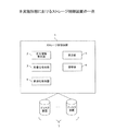
図1は、本実施形態におけるストレージ制御装置の一例を示す。ストレージ制御装置1は、劣化情報要求部2、再書込指示部3を含む。
劣化情報要求部2は、データを記憶する複数のディスク装置7に対して、記憶されているデータの劣化に関する劣化情報を通知するように要求する。劣化情報要求部2の一例として、ATIスキャン指示部132が挙げられる。
FIG. 1 shows an example of a storage control apparatus according to this embodiment. The storage control device 1 includes a deterioration
The deterioration
再書込指示部3は、複数のディスク装置7から通知された劣化情報のうち1以上のディスク装置から通知された、データの再書き込みの契機となる劣化情報に基づいて複数のディスク装置7に対して、再書き込みを行うように指示する。再書込指示部3の一例として、ATIリフレッシュ指示部133が挙げられる。
The rewrite instructing
このように構成することにより、各ディスク装置7におけるデータ劣化に関する再書き込み処理を同期して実行することができる。
With this configuration, rewrite processing relating to data deterioration in each
複数のディスク装置7は、それぞれ独立して、データの劣化に関する判定を行う判定機能と、判定の結果に基づいて、それぞれ独立して、データの再書き込みを行なう再書き込み機能と、を有する。ストレージ制御装置1は、さらに、無効化指示部4を含む。無効化指示部4は、複数のディスク装置7から通知された劣化情報のうち1以上のディスク装置7から通知された、データの再書き込みの契機となる劣化情報に基づいて、複数のディスク装置7に対して、再書き込み機能を無効にする無効化指示を行う。この機能は、独立して、データの劣化に関する判定を行い、判定の結果、データの劣化によりデータの再書き込みを必要とする際には、前記データの再書き込みを行う機能である。無効化指示部4の一例として、切替指示部134が挙げられる。劣化情報要求部2は、無効化指示により複数のディスク装置7のそれぞれの書き込み機能が無効化されたことを確認した場合に、複数のディスク装置7に対して、劣化情報を通知するように要求する。
Each of the plurality of
このように構成することにより、各ディスク装置が独立して実行していた再書き込みを停止させて、ストレージ制御装置は再書き込み処理のタイミングを一元管理することができる。 With this configuration, the storage controller can centrally manage the timing of the rewrite process by stopping the rewrite that has been executed independently by each disk device.
ストレージ制御装置1は、さらに、計測部5を含む。計測部5は、複数のディスク装置7への書き込み処理の回数を計測する。計測部5の一例として、カウンタ更新部135が挙げられる。劣化情報要求部2は、計測された書き込み処理の回数が第1の閾値以上である場合、複数のディスク装置7のそれぞれに対して、劣化情報を通知するように要求する。再書込指示部3は、第2の閾値以上の数のディスク装置から通知された、データの再書き込みの契機となる劣化情報に基づいて、複数のディスク装置に対して、データの再書き込みを行うように指示する。
The storage control device 1 further includes a
第1の閾値、第2の閾値はそれぞれ、ディスク装置により構築されるRAIDグループの種別に応じて、設定される。第1の閾値の一例として、本実施形態の閾値T1が挙げられる。第2の閾値の一例として、本実施形態の閾値T2が挙げられる。RAIDグループの種別に応じて、第1の閾値、第2の閾値を選択することにより、RAIDグループの種別に応じて、ATIスキャンのタイミング及びATIリフレッシュのタイミングを調整することができる。 The first threshold value and the second threshold value are respectively set according to the type of RAID group constructed by the disk device. An example of the first threshold is the threshold T1 of the present embodiment. An example of the second threshold is the threshold T2 of the present embodiment. By selecting the first threshold value and the second threshold value according to the type of the RAID group, the timing of the ATI scan and the timing of the ATI refresh can be adjusted according to the type of the RAID group.
ストレージ制御装置1は、さらに、調整部6を含む。調整部6は、前記書き込み処理の回数に応じて、前記ディスク装置による前記データの劣化の検出の頻度を調整する。調整部6の一例として、スキャン頻度調整部136が挙げられる。
The storage control device 1 further includes an adjustment unit 6. The adjusting unit 6 adjusts the frequency of detection of the deterioration of the data by the disk device according to the number of times of the writing process. An example of the adjustment unit 6 is a scan
このように構成することにより、再設定値を新たな閾値T1として用いることで、ATIスキャン回数の頻度を減らすことができ、ATIスキャン実施による性能影響の低減を図ることができる。 With this configuration, by using the reset value as the new threshold value T1, the frequency of the number of ATI scans can be reduced, and the performance influence due to the ATI scan can be reduced.
以下に、本実施形態の詳細を説明する。
図2は、本実施形態におけるストレージ装置の一例を示す。ストレージ装置11は、RAIDコントローラ12、RAIDグループ21を含む。RAIDグループ21は、複数のディスク装置22を含み、RAIDを構成する。
Details of this embodiment will be described below.
FIG. 2 shows an example of a storage apparatus according to this embodiment. The
RAIDコントローラ12は、複数のディスク装置22により構築されるRAIDグループ21等を管理する。RAIDコントローラ12は、制御部13、記憶部18、インターフェース20を含む。
The
記憶部18は、例えば、キャッシュメモリ、ROM(Read Only Memory)、RAM(Random Access Memory)等の情報を記録するデバイスである。記憶部18には、動作タイミング管理テーブル19が格納される。
The
制御部13は、例えば、ASIC(Application Specific Integrated Circuit)やFPGA(Field Programmable Gate Array)等の集積回路またはCPU(Central Processing Unit)やMPU(Micro Processing Unit)等の電子回路である。制御部13は、ATI管理情報要求部131、ATIスキャン指示部132、ATIリフレッシュ指示部133、切替指示部134、カウンタ更新部135、スキャン頻度調整部136として機能する。
The control unit 13 is, for example, an integrated circuit such as an ASIC (Application Specific Integrated Circuit) or an FPGA (Field Programmable Gate Array) or an electronic circuit such as a CPU (Central Processing Unit) or an MPU (Micro Processing Unit). The control unit 13 functions as an ATI management
ATI管理情報要求部131は、各ディスク装置22からの起動後の準備完了の通知を受信したことを契機に、ディスク装置22にATI管理情報を送信するように要求するコマンド(ATI管理情報要求コマンド)を発行する。ATI管理情報は、ATIを管理する記憶領域(管理領域)に対応するLBA範囲情報と、ATIスキャンを実行するために用いるライト回数の閾値情報と、ライト回数カウンタ情報を含む。ATI管理情報要求部131は、ATI管理情報要求コマンド実行の結果、各ディスク装置22から取得したATI管理情報を用いて、動作タイミング管理テーブル19を作成する。
The ATI management
ATIスキャン指示部132は、動作タイミング管理テーブル19に基づいて、各ディスク装置22に対し、ATIスキャン動作を起動させるコマンド(ATIスキャンコマンド)を発行する。
The ATI
ATIリフレッシュ指示部133は、ATIスキャンの結果と、ディスク装置22により構成されるRAIDレベルとに応じて、ATIリフレッシュの実施の要否を判定する。ATIリフレッシュの実施が必要と判定した場合、ATIリフレッシュ指示部133は、各ディスク装置22に対し、ATIリフレッシュ動作を起動させるコマンド(ATIリフレッシュコマンド)を発行する。
The ATI
切替指示部134は、ディスク装置22が自動でATIスキャン動作及びATIリフレッシュ動作を行う機能を有効(ON)にしたり、無効(OFF)したりすることを切り替えるコマンド(切替コマンド)を発行する。
The switching
カウンタ更新部135は、ライト処理の回数を計測し、その計測値を用いて、動作タイミング管理テーブル19を更新する。
The
スキャン頻度調整部136は、ATIスキャンのタイミングを適正にするために、ATIスキャン回数の頻度を調整する。
The scan
インターフェース(「I/F」と称する)20は、各ディスク装置22と接続されており、制御部13とディスク装置22との間のデータ転送を媒介する。
The interface (referred to as “I / F”) 20 is connected to each
ディスク装置22は、自身の内部処理であるATIスキャン処理及びATIリフレッシュ処理について、I/F20を介し、RAIDコントローラ12からの切替コマンドにより、自動ATIスキャン/ATIリフレッシュ機能のON/OFFの変更をする。また、ディスク装置22は、RAIDコントローラ12からの取得コマンド発行に対して、ATI管理情報を送信する。また、ディスク装置22は、RAIDコントローラ12からのATIスキャンコマンド/ATIリフレッシュコマンドの発行に対して、ATIスキャン/ATIリフレッシュを実行する。
The
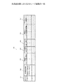
図3は、本実施形態における動作タイミング管理テーブルの一例を示す。ATI管理情報要求部131は、取得コマンドの発行により、RAIDレベルごとに、以下のデータ項目を含む動作タイミング管理テーブル19を作成する。
FIG. 3 shows an example of the operation timing management table in the present embodiment. The ATI management
動作タイミング管理テーブル19は、「RAID No.」31、「管理領域範囲」32、「閾値T1」33、「ライト回数カウンタ」34、「ATIスキャン実行回数」35、「閾値T2」36、「ATIリフレッシュ対象数」37のデータ項目を含む。 The operation timing management table 19 includes “RAID No.” 31, “management area range” 32, “threshold T1” 33, “write count counter” 34, “ATI scan execution count” 35, “threshold T2” 36, “ATI”. Data items of “number of refresh targets” 37 are included.
「RAID No.」31は、RAIDレベルを識別する識別情報を示す。「管理領域範囲」32は、ディスク装置22が管理しているATIスキャン領域の範囲を示す。「閾値T1」33は、ATIスキャンを実行するためのライト回数の閾値を示す。「ライト回数カウンタ」34は、ライト回数を示す。「ATIスキャン実行回数」35は、ATIスキャンコマンドを実行した回数を示す。「閾値T2」36は、ATIリフレッシュを実行するのに必要なディスク装置22の数の閾値を示す。「ATIリフレッシュ対象数」37は、ATIリフレッシュの実行が必要なディスク装置数を示す。
“RAID No.” 31 indicates identification information for identifying a RAID level. The “management area range” 32 indicates the range of the ATI scan area managed by the
「閾値T1」33、「閾値T2」36には、予め値が設定されているが、後述するように、「閾値T1」33は、実際のスキャン回数に応じて再設定される。 Although “threshold value T1” 33 and “threshold value T2” 36 are preset, as described later, “threshold value T1” 33 is reset according to the actual number of scans.
次に、ATIスキャン、ATIリフレッシュの制御方法について説明する。図4で説明するように、ATIスキャンのタイミング、及びATIリフレッシュのタイミングは、RAIDレベルに応じて、3つのグループに分けることができる。RAIDの構成は、冗長性を持たせたデータの生成方法と配置方法により複数の種別に分類することができる。RAIDレベルとは、その分類された定義を示す値であり、RAID0、RAID0+1、RAID1、RAID1+0、RAID5、RAID6等で表記される。 Next, a method for controlling ATI scan and ATI refresh will be described. As illustrated in FIG. 4, the ATI scan timing and the ATI refresh timing can be divided into three groups according to the RAID level. The RAID configuration can be classified into a plurality of types according to a data generation method and an arrangement method with redundancy. The RAID level is a value indicating the classified definition, and is expressed in RAID0, RAID0 + 1, RAID1, RAID1 + 0, RAID5, RAID6, or the like.
図4は、本実施形態における、RAIDレベルに応じたATIスキャン及びATIリフレッシュのタイミングについて説明するための図である。RAIDレベルに応じてグループに分けられる。グループ1には、RAIDレベルが“RAID0”が含まれる。グループ2には、RAI0+1、RAID1、RAID1+0、RAID5、RAID5+0が含まれる。グループ3には、RAID6が含まれる。このように、RAIDレベルに応じてRAIDグループを3グループに分けるのは、RAID内で、ATIスキャン/ATIリフレッシュ実施によるパフォーマンス影響が小さい(ATIスキャン/ATIリフレッシュ実施の頻度が少ない)、冗長性の2点を考慮したことによる。
FIG. 4 is a diagram for explaining the timing of ATI scan and ATI refresh according to the RAID level in the present embodiment. They are divided into groups according to the RAID level. Group 1 includes RAID level “RAID0”.
グループ1は、RAIDを構成する1台のディスク装置が故障するとRAID故障となるグループである。グループ2は、RAIDを構成する2台のディスク装置が故障するとRAID故障となるグループである。グループ3は、RAIDを構成する3台のディスクが故障するとRAID故障となるグループである。
Group 1 is a group in which a RAID failure occurs when one disk device constituting a RAID fails.
まずは、ストレージ装置11のRAIDレベルがグループ1に該当する場合について説明する。ディスク装置が有する閾値のうち、最小の閾値T1を用いて、ライト回数が閾値T1に達したときに、ATIスキャンが行われる。また、RAIDを構成するディスク装置22のうち、いずれかがATIリフレッシュの必要があると応答したときに、ATIリフレッシュが行われる。
First, a case where the RAID level of the
ストレージ装置11のRAIDレベルがグループ2に該当する場合について説明する。RAIDグループ内のディスク装置が有する閾値のうち、2番目に小さい閾値T1を用いて、ライト回数が閾値T1に達したときに、ATIスキャンが行われる。また、RAIDを構成するディスク装置のうち、ディスク装置2台がATIリフレッシュの必要があると応答したときに、ATIリフレッシュが行われる。
A case where the RAID level of the
ストレージ装置11のRAIDレベルがグループ3に該当する場合について説明する。ディスク装置が有する閾値のうち、3番目に小さい閾値T1を用いて、ライト回数が閾値T1に達したときに、ATIスキャンが行われる。また、RAIDを構成するディスク装置のうち、ディスク装置3台がATIリフレッシュの必要があると応答したときに、ATIリフレッシュが行われる。
A case where the RAID level of the
次に、ATIスキャンタイミングの学習方法について説明する。ATIリフレッシュタイミングが、ATIスキャンを3回以上実施した場合に到来した場合(ATIスキャン閾値再設定タイミング)には、閾値T1を以下の算出式を用い再設定する。すなわち、ATIスキャンタイミング到来時のATIスキャン回数が以下の条件式(1)
ATIスキャンタイミング到来時のATIスキャン回数≧3 ・・・(1)
に当てはまる場合は、ATIスキャン実行するためのライト回数についての閾値T1を再設定するために、以下の式(2)を用いて、再設定を行う。
再設定値=(ATIリフレッシュタイミング到来時のATIスキャン回数)×
(元の閾値T1)÷2 ・・・(2)
この再設定値を新たな閾値T1として用いることで、ATIスキャン回数の頻度を減らすことができ、ATIスキャン実施による性能影響の低減を図ることができる。
Next, a method for learning ATI scan timing will be described. When the ATI refresh timing comes when the ATI scan is performed three times or more (ATI scan threshold reset timing), the threshold T1 is reset using the following calculation formula. That is, the number of ATI scans when the ATI scan timing arrives is the following conditional expression (1)
Number of ATI scans when the ATI scan timing arrives ≧ 3 (1)
If this is true, resetting is performed using the following equation (2) in order to reset the threshold T1 for the number of writes for executing the ATI scan.
Reset value = (ATI scan count when ATI refresh timing comes) x
(Original threshold value T1) ÷ 2 (2)
By using this reset value as the new threshold value T1, the frequency of the number of ATI scans can be reduced, and the performance impact due to the ATI scan can be reduced.
本実施形態におけるストレージ装置11の動作は、RAIDボリューム作成時でのRAIDグループの再構成時の動作タイミング管理テーブル19の作成処理と、RAIDコントローラ12によるATIスキャン/ATIリフレッシュ処理の2つに大別される。これらの処理の詳細についてはそれぞれ、図5、図6を用いて説明する。なお、RAIDグループの再構成とは、RAIDグループを構成するディスク装置が交換等により変更されることにより、再度RAIDグループを構成することをいう。RAIDボリュームとは、ディスク装置22が有する記憶領域における、1又は複数のRAID方式に基づく論理ボリュームを表す。
The operation of the
次に、図5、及び図6を用いて、本実施形態に係るRAIDコントローラ12のフローについて説明する。このとき、RAIDコントローラ12の制御部13は、ATI管理情報要求部131、ATIスキャン指示部132、ATIリフレッシュ指示部133、切替指示部134、カウンタ更新部135、スキャン頻度調整部136として機能する。
Next, the flow of the
図5は、本実施形態における、RAIDボリューム作成時のRAIDグループの再構成時の動作タイミング管理テーブルの作成処理フローの一例を示す。RAIDボリューム作成時に、ストレージ装置11は、以下の動作を行い、動作タイミング管理テーブル19を作成する。
FIG. 5 shows an example of an operation timing management table creation processing flow at the time of RAID group reconfiguration when creating a RAID volume in the present embodiment. When creating the RAID volume, the
まず、切替指示部134は、各ディスク装置22に対し、自動でATIスキャン及びATIリフレッシュを実行する機能(自動ATIスキャン/ATIリフレッシュ機能)をOFFにするコマンドを発行する(S1)。ディスク装置22は、自動ATIスキャン/ATIリフレッシュをOFFにするコマンドを受信すると、そのコマンドを実行し、その実行結果(正常終了か異常終了かを示すステータス)をRAIDコントローラ12へ応答する。
First, the switching
切替指示部134は、RAIDグループ21内の全ディスク装置22から、自動ATIスキャン/ATIリフレッシュをOFFにするコマンドを実行した結果(応答結果)を受信する(S2)。
The switching
全てのディスク装置22において、自動ATIスキャン/ATIリフレッシュをOFFにするコマンドの実行結果が正常終了でない場合(S3で「No」)、切替指示部134は、次の処理を行う。すなわち、切替指示部134は、各ディスク装置22に対し、自動ATIスキャン/ATIリフレッシュ機能をONにするコマンドを発行する(S8)。なお、切替指示部134は、自動ATIスキャン/ATIリフレッシュをOFFにするコマンドの実行結果が異常終了であるディスク装置22に対して、自動ATIスキャン/ATIリフレッシュ機能をONにするコマンドを発行してもよい。ディスク装置22は、自動ATIスキャン/ATIリフレッシュ機能をONにするコマンドを受信すると、自動ATIスキャン/ATIリフレッシュを実施する。
In all the
RAIDグループ21内の全ディスク装置22から受信した、自動ATIスキャン/ATIリフレッシュ機能をOFFにするコマンドの実行結果が正常終了である場合(S3で「Yes」)、切替指示部134は、自動ATIスキャン/ATIリフレッシュ機能がOFFであると判断する。この場合、ATI管理情報要求部131は、各ディスク装置22に対してATI管理情報の送信を要求するコマンド(ATI管理情報要求コマンド)を発行する(S4)。
When the execution result of the command for turning off the automatic ATI scan / ATI refresh function received from all the
ディスク装置22は、ATI管理情報要求コマンドを受信すると、そのコマンドを実行する。ディスク装置22は、ATI管理情報要求コマンドの実行結果(正常終了か異常終了かを示すステータス)と、ATI管理情報とをRAIDコントローラ12に応答する。ATI管理情報要求部131は、ディスク装置22から、ATI管理情報要求コマンドに対する実行結果(ステータス)と、ATI管理情報を受信する(S5)。
When receiving the ATI management information request command, the
ATI管理情報要求コマンドの実行結果が異常終了の場合(S6で「No」)、切替指示部134は、各ディスク装置22に対して、自動ATIスキャン/ATIリフレッシュ機能をONにするコマンドを発行する(S8)。自動ATIスキャン/ATIリフレッシュ機能をONにするコマンドを受信すると、ディスク装置22は、そのコマンドを実行し、自動ATIスキャン/ATIリフレッシュ機能をONにする。すると、ディスク装置22は、自動ATIスキャン/ATIリフレッシュを実施する。
When the execution result of the ATI management information request command is abnormally terminated (“No” in S6), the switching
ATI管理情報の送信を要求するコマンドの実行結果が正常終了の場合(S6で「Yes」)、ATI管理情報要求部131は、受信したATI管理情報を用いて、動作タイミング管理テーブル19を作成する(S7)。
When the execution result of the command requesting transmission of the ATI management information is normal termination (“Yes” in S6), the ATI management
RAIDグループ21内のディスク装置22の再構成があるごとに、RAIDコントローラ12は、新たにRAIDグループ21に追加されたディスク装置22に対してS1〜S7を実施し、動作タイミング管理テーブル19を更新する。
Each time there is a reconfiguration of the
これにより、動作タイミング管理テーブル19が作成され、それにより、RAIDコントローラ12は、動作タイミング管理テーブル19を参照して、RAIDグループの種別(RAIDレベル)を特定することができる。
As a result, the operation timing management table 19 is created, whereby the
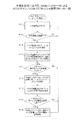
図6は、本実施形態における、RAIDコントローラによるATIスキャン/ATIATIリフレッシュ処理フローの一例を示す。図5のフローにおいて、RAIDコントローラ12は、RAIDグループの種別(RAIDレベル)を認識する。RAIDコントローラ12は、図4で説明したようにそのRAIDレベルに応じて、ディスク装置を選択し、そのディスク装置の閾値T1を設定する。
FIG. 6 shows an example of an ATI scan / ATIATI refresh process flow by the RAID controller in the present embodiment. In the flow of FIG. 5, the
カウンタ更新部135は、上記で選択したディスク装置21の入出力処理において実行されるライト処理の回数(ライト回数)をカウントし、動作タイミング管理テーブル19の「ライト回数」34を更新する(S11)。カウンタ更新部135は、カウントしたライト回数が閾値T1に到達したかを判断する(S12)。カウントしたライト回数が閾値T1に到達していない場合(S12で「No」)、S11の処理へ戻る。
The
カウントしたライト回数が閾値T1に到達した場合(S12で「Yes」)、ATIスキャン指示部132は、RAIDグループ21を構成する全ディスク装置22に対して、ATIスキャンコマンドを発行する(S13)。ATIスキャンコマンドを受信すると、ディスク装置22は、ATIスキャンを行い、ATIによるデータ消失具合を診断する。ディスク装置22は、そのATIスキャンコマンドの実行結果(データ消去具合が閾値TT2を超えたか否かを示す情報、スキャン実行回数等)をRAIDコントローラ12へ応答する。
When the counted number of writes reaches the threshold value T1 (“Yes” in S12), the ATI
ATIスキャン指示部132は、全ディスク装置22からATIスキャンコマンド実行結果を受信する。ATIスキャン指示部132は、そのATIスキャンコマンド実行結果に基づいて、動作タイミング管理テーブル19の「ATIスキャン実行回数」35、「ATIリフレッシュ対象数」37を更新する(S14)。
The ATI
ATIリフレッシュ指示部133は、図4で説明したように、RAIDグループ21のRAIDレベルに応じたATIリフレッシュタイミングが到来したかを判定する(S15)。すなわち、ATIリフレッシュ指示部133は、動作タイミング管理テーブル19の「ATIリフレッシュ対象数」37の値が閾値T2以上であるかを判断する。
As described with reference to FIG. 4, the ATI
ATIリフレッシュタイミングが到来していない場合(S15で「No」)、S11の処理へ戻る。 If the ATI refresh timing has not arrived (“No” in S15), the process returns to S11.
ATIリフレッシュタイミングが到来している場合(S15で「Yes」)、ATIリフレッシュ指示部133は、RAIDグループ21内の全ディスク装置22に対して、ATIリフレッシュコマンドを発行する(S16)。ディスク装置22は、ATIリフレッシュコマンドを受信すると、ATIリフレッシュコマンドを実行し、動作タイミング管理テーブル19の「管理領域範囲」32に対応するデータを書き直す。ディスク装置22は、ATIリフレッシュコマンドの実行結果をRAIDコントローラ12へ応答する。
When the ATI refresh timing has arrived (“Yes” in S15), the ATI
ATIリフレッシュ指示部133は、全ディスク装置22からATIリフレッシュコマンドの実行結果を受信する(S17)。
The ATI
スキャン頻度調整部136は、ATIスキャンタイミングが、ATIスキャンタイミングを再調整するための条件式(1)に当てはまる場合には、再設定式(2)を従い、ATI スキャンを実施するタイミングを再設定する(S19)。ATIスキャンタイミングを再調整するための条件式(1)に当てはまらない場合には、S11に戻る。
The scan
本実施形態によれば、ディスク装置が自律的にATIリフレッシュ動作の影響による性能劣化を最小化するために、RAIDコントローラはRAIDグループに属する全てのディスク装置のATIリフレッシュ動作を同期して実行するように制御することができる。このとき、RAIDコントローラはより適切なタイミングでATIリフレッシュを実行することを制御することができる。 According to this embodiment, in order for the disk device to autonomously minimize performance degradation due to the influence of the ATI refresh operation, the RAID controller executes the ATI refresh operation of all the disk devices belonging to the RAID group synchronously. Can be controlled. At this time, the RAID controller can control execution of ATI refresh at a more appropriate timing.
なお、本発明は、以上に述べた実施の形態に限定されるものではなく、本発明の要旨を逸脱しない範囲内で種々の構成または実施形態を取ることができる。 The present invention is not limited to the above-described embodiment, and various configurations or embodiments can be taken without departing from the gist of the present invention.
1 ストレージ制御装置
2 劣化情報要求部
3 再書込指示部
4 無効化指示部
5 計測部
6 調整部
7 ディスク装置
11 ストレージ装置
12 RAIDコントローラ
13 制御部
131 ATI管理情報要求部
132 ATIスキャン指示部
133 ATIリフレッシュ指示部
134 切替指示部
135 カウンタ更新部
136 スキャン頻度調整部
18 記憶部
19 動作タイミング管理テーブル
20 インターフェース
21 RAIDグループ
22 ディスク装置
DESCRIPTION OF SYMBOLS 1
Claims (8)
前記複数のディスク装置から通知された劣化情報のうち1以上のディスク装置から通知された、データの再書き込みの契機となる劣化情報に基づいて前記複数のディスク装置の全てに対して、該再書き込みを行うように指示する再書込指示部と、
を備えることを特徴とするストレージ制御装置。 A deterioration information requesting unit that requests a plurality of disk devices for storing data to notify deterioration information relating to deterioration of stored data;
Rewriting to all of the plurality of disk devices based on degradation information notified from one or more disk devices among the degradation information notified from the plurality of disk devices, which triggers data rewriting. A rewriting instruction unit for instructing to perform
A storage control apparatus comprising:
それぞれ独立して、データの劣化に関する判定を行う判定機能と、
該判定の結果に基づいて、それぞれ独立して、データの再書き込みを行なう再書き込み機能と、を有し、
前記ストレージ制御装置は、さらに、
前記複数のディスク装置から通知された劣化情報のうち1以上のディスク装置から通知された、データの再書き込みの契機となる劣化情報に基づいて、前記複数のディスク装置に対して、前記再書き込み機能を無効にする無効化指示を行う無効化指示部
を備えることを特徴とする請求項1に記載のストレージ制御装置。 The plurality of disk devices are:
A decision function for making a decision on data degradation independently,
A rewriting function for rewriting data independently based on the result of the determination, and
The storage control device further includes:
The rewrite function for the plurality of disk devices based on the degradation information notified from one or more disk devices among the degradation information notified from the plurality of disk devices, which triggers data rewriting. The storage control device according to claim 1, further comprising: an invalidation instruction unit that issues an invalidation instruction for invalidating the storage device.
ことを特徴とする請求項2に記載のストレージ制御装置。 The deterioration information requesting unit, when it is confirmed that each of the rewrite function of the plurality of disk devices by the invalidation instruction is disabled, to the plurality of disk devices, notifying the deterioration information The storage control device according to claim 2, wherein the storage control device is requested to do so.
前記複数のディスク装置への書き込み処理の回数を計測する計測部と、
を備え、
前記劣化情報要求部は、計測された前記書き込み処理の回数が第1の閾値以上である場合、前記複数のディスク装置のそれぞれに対して、前記劣化情報を通知するように要求し、
前記再書込指示部は、第2の閾値以上の数の前記ディスク装置から通知された、データの再書き込みの契機となる劣化情報に基づいて、前記複数のディスク装置に対して、該データの再書き込みを行うように指示する
ことを特徴とする請求項1〜3のうちいずれか1項に記載のストレージ制御装置。 The storage control device further includes:
A measuring unit for measuring the number of times of writing processing to the plurality of disk devices;
With
The degradation information requesting unit requests the degradation information to be notified to each of the plurality of disk devices when the measured number of write processes is equal to or greater than a first threshold;
The rewrite instructing unit sends the data to the plurality of disk devices based on deterioration information notified from the number of the disk devices equal to or greater than a second threshold and triggering data rewrite. The storage control device according to any one of claims 1 to 3, wherein an instruction is given to perform rewriting.
ことを特徴とする請求項4に記載のストレージ制御装置。 The storage control device according to claim 4 , wherein each of the first threshold value and the second threshold value is set according to a type of a RAID group constructed by the disk device.
前記書き込み処理の回数に応じて、前記ディスク装置による前記データの劣化の検出の頻度を調整する調整部と、
を備えることを特徴とする請求項4又は5に記載のストレージ制御装置。 The storage control device further includes:
An adjustment unit that adjusts the frequency of detection of deterioration of the data by the disk device according to the number of times of the writing process;
The storage control device according to claim 4, comprising:
データを記憶する複数のディスク装置に対して、記憶されているデータの劣化に関する劣化情報を通知するように要求し、
前記複数のディスク装置から通知された劣化情報のうち1以上のディスク装置から通知された、データの再書き込みの契機となる劣化情報に基づいて前記複数のディスク装置の全てに対して、該再書き込みを行うように指示する、
処理を実行させることを特徴とするストレージ制御プログラム。 On the computer,
Requests a plurality of disk devices for storing data to notify deterioration information related to deterioration of stored data,
Rewriting to all of the plurality of disk devices based on degradation information notified from one or more disk devices among the degradation information notified from the plurality of disk devices, which triggers data rewriting. Instruct to do the
A storage control program for executing a process.
前記コンピュータは、
データを記憶する複数のディスク装置に対して、記憶されているデータの劣化に関する劣化情報を通知するように要求し、
前記複数のディスク装置から通知された劣化情報のうち1以上のディスク装置から通知された、データの再書き込みの契機となる劣化情報に基づいて前記複数のディスク装置の全てに対して、該再書き込みを行うように指示する、
ことを特徴とするストレージ制御方法。 A storage control method executed by a computer,
The computer
Requests a plurality of disk devices for storing data to notify deterioration information related to deterioration of stored data,
Rewriting to all of the plurality of disk devices based on degradation information notified from one or more disk devices among the degradation information notified from the plurality of disk devices, which triggers data rewriting. Instruct to do the
Storage control method, characterized in that.
Priority Applications (2)
| Application Number | Priority Date | Filing Date | Title |
|---|---|---|---|
| JP2013074770A JP6155768B2 (en) | 2013-03-29 | 2013-03-29 | Storage control device, storage control program, and storage control method |
| US14/187,634 US9372763B2 (en) | 2013-03-29 | 2014-02-24 | Storage control device and storage control method |
Applications Claiming Priority (1)
| Application Number | Priority Date | Filing Date | Title |
|---|---|---|---|
| JP2013074770A JP6155768B2 (en) | 2013-03-29 | 2013-03-29 | Storage control device, storage control program, and storage control method |
Publications (2)
| Publication Number | Publication Date |
|---|---|
| JP2014199578A JP2014199578A (en) | 2014-10-23 |
| JP6155768B2 true JP6155768B2 (en) | 2017-07-05 |
Family
ID=51622063
Family Applications (1)
| Application Number | Title | Priority Date | Filing Date |
|---|---|---|---|
| JP2013074770A Expired - Fee Related JP6155768B2 (en) | 2013-03-29 | 2013-03-29 | Storage control device, storage control program, and storage control method |
Country Status (2)
| Country | Link |
|---|---|
| US (1) | US9372763B2 (en) |
| JP (1) | JP6155768B2 (en) |
Family Cites Families (21)
| Publication number | Priority date | Publication date | Assignee | Title |
|---|---|---|---|---|
| JPS5963015A (en) * | 1982-10-04 | 1984-04-10 | Hitachi Ltd | Rotable body magnetic memory device |
| JPH0249300A (en) * | 1988-08-10 | 1990-02-19 | Fujitsu Ltd | Microcomputer incorporated with eeprom |
| US6230233B1 (en) * | 1991-09-13 | 2001-05-08 | Sandisk Corporation | Wear leveling techniques for flash EEPROM systems |
| JPH09245349A (en) * | 1996-03-08 | 1997-09-19 | Hitachi Ltd | Magnetic recording and reproducing device |
| US6442705B1 (en) * | 1999-04-26 | 2002-08-27 | International Business Machines Corporation | Method of and apparatus for improving data integrity in a disk drive system |
| US7467274B2 (en) * | 2001-12-31 | 2008-12-16 | Hewlett-Packard Development Company, L.P. | Method to increase the life span of limited cycle read/write media |
| JP4063694B2 (en) * | 2003-03-11 | 2008-03-19 | 株式会社日立グローバルストレージテクノロジーズ | Magnetic disk unit |
| US7137038B2 (en) * | 2003-07-29 | 2006-11-14 | Hitachi Global Storage Technologies Netherlands, B.V. | System and method for autonomous data scrubbing in a hard disk drive |
| US7475276B2 (en) | 2004-05-07 | 2009-01-06 | Equallogic, Inc. | Method for maintaining track data integrity in magnetic disk storage devices |
| JP2007133683A (en) * | 2005-11-10 | 2007-05-31 | Sony Corp | Memory system |
| JP2007242207A (en) * | 2006-03-13 | 2007-09-20 | Fujitsu Ltd | Medium scanning method of disk device |
| JP2008243269A (en) * | 2007-03-26 | 2008-10-09 | Hitachi Global Storage Technologies Netherlands Bv | Disk driving device and data rewriting method thereof |
| JP5192352B2 (en) * | 2008-10-30 | 2013-05-08 | 株式会社日立製作所 | Storage device and data storage area management method |
| JP2010157278A (en) * | 2008-12-26 | 2010-07-15 | Toshiba Corp | Disk storage device and method for processing defect |
| JP5264630B2 (en) * | 2009-06-23 | 2013-08-14 | エイチジーエスティーネザーランドビーブイ | Magnetic disk drive and data rewrite method |
| US8023215B1 (en) * | 2010-05-25 | 2011-09-20 | Seagate Technology Llc | Data recovery scan based on head performance |
| JP4865062B2 (en) | 2010-06-30 | 2012-02-01 | 株式会社東芝 | Magnetic disk device and refresh method in the same |
| JP5663981B2 (en) * | 2010-07-01 | 2015-02-04 | 富士通株式会社 | Storage device, storage device controller, and storage device control method |
| JPWO2012105260A1 (en) * | 2011-02-04 | 2014-07-03 | パナソニック株式会社 | Storage device |
| US8898373B1 (en) * | 2011-06-29 | 2014-11-25 | Western Digital Technologies, Inc. | System and method for improving wear-leveling performance in solid-state memory |
| JP2013062006A (en) * | 2011-09-14 | 2013-04-04 | Hitachi-Lg Data Storage Inc | Optical disk library devices and optical disk device selection method |
-
2013
- 2013-03-29 JP JP2013074770A patent/JP6155768B2/en not_active Expired - Fee Related
-
2014
- 2014-02-24 US US14/187,634 patent/US9372763B2/en active Active
Also Published As
| Publication number | Publication date |
|---|---|
| JP2014199578A (en) | 2014-10-23 |
| US20140298089A1 (en) | 2014-10-02 |
| US9372763B2 (en) | 2016-06-21 |
Similar Documents
| Publication | Publication Date | Title |
|---|---|---|
| US8069301B2 (en) | Apparatus, storage system, and computer program product for prevention of data loss | |
| US8824261B1 (en) | Peer to peer vibration mitigation | |
| US9344525B2 (en) | Method and apparatus for data migration | |
| CN101145372B (en) | Disk drive with nonvolatile memory for storage of failure-related data | |
| US8880801B1 (en) | Techniques for reliability and availability assessment of data storage configurations | |
| JP6017065B2 (en) | Storage system and cache control method | |
| US10067840B1 (en) | Life expectancy data migration | |
| JP6331773B2 (en) | Storage control device and storage control program | |
| JP2013161476A (en) | System and method for improving reconstruction of raid(redundant array of independent disks) | |
| JP2005122338A (en) | Disk array device having spare disk drive, and data sparing method | |
| JP4792490B2 (en) | Storage controller and RAID group expansion method | |
| US9218849B1 (en) | Data loss mitigation in a heat assisted magnetic recording data storage device | |
| JP4438010B2 (en) | Relay device, relay method, and relay control program | |
| US20100100677A1 (en) | Power and performance management using MAIDx and adaptive data placement | |
| JP5198659B2 (en) | Storage control device and control method of storage control device | |
| JP2008027240A (en) | Disk array device, patrol diagnostic method, and patrol diagnostic control program | |
| JP2017068754A (en) | Storage control device and control program | |
| JP6155768B2 (en) | Storage control device, storage control program, and storage control method | |
| JP2013206151A (en) | Storage device and data storage device exchange method of storage device | |
| CN115407928A (en) | Adaptive read scrubbing | |
| JP5418687B2 (en) | Storage medium diagnosis apparatus, storage medium diagnosis method, and storage medium diagnosis program | |
| JP4862841B2 (en) | Storage apparatus, system, method, and program | |
| JP2016004592A (en) | Control device, diagnosis control program and diagnosis control method | |
| JP2023044428A (en) | RAID device | |
| JP2016035687A (en) | Disk array device and disk array device control method |
Legal Events
| Date | Code | Title | Description |
|---|---|---|---|
| A621 | Written request for application examination |
Free format text: JAPANESE INTERMEDIATE CODE: A621 Effective date: 20151204 |
|
| A977 | Report on retrieval |
Free format text: JAPANESE INTERMEDIATE CODE: A971007 Effective date: 20161026 |
|
| A131 | Notification of reasons for refusal |
Free format text: JAPANESE INTERMEDIATE CODE: A131 Effective date: 20161115 |
|
| A521 | Request for written amendment filed |
Free format text: JAPANESE INTERMEDIATE CODE: A523 Effective date: 20161208 |
|
| TRDD | Decision of grant or rejection written | ||
| A01 | Written decision to grant a patent or to grant a registration (utility model) |
Free format text: JAPANESE INTERMEDIATE CODE: A01 Effective date: 20170509 |
|
| A61 | First payment of annual fees (during grant procedure) |
Free format text: JAPANESE INTERMEDIATE CODE: A61 Effective date: 20170522 |
|
| R150 | Certificate of patent or registration of utility model |
Ref document number: 6155768 Country of ref document: JP Free format text: JAPANESE INTERMEDIATE CODE: R150 |
|
| LAPS | Cancellation because of no payment of annual fees |