JP6153632B2 - Tissue ablation cannula / electrode assembly selectively operable by one or more active tips - Google Patents
Tissue ablation cannula / electrode assembly selectively operable by one or more active tips Download PDFInfo
- Publication number
- JP6153632B2 JP6153632B2 JP2015559217A JP2015559217A JP6153632B2 JP 6153632 B2 JP6153632 B2 JP 6153632B2 JP 2015559217 A JP2015559217 A JP 2015559217A JP 2015559217 A JP2015559217 A JP 2015559217A JP 6153632 B2 JP6153632 B2 JP 6153632B2
- Authority
- JP
- Japan
- Prior art keywords
- cannula
- electrode
- hub
- electrode assembly
- assembly according
- Prior art date
- Legal status (The legal status is an assumption and is not a legal conclusion. Google has not performed a legal analysis and makes no representation as to the accuracy of the status listed.)
- Active
Links
Images


Classifications
-
- A—HUMAN NECESSITIES
- A61—MEDICAL OR VETERINARY SCIENCE; HYGIENE
- A61B—DIAGNOSIS; SURGERY; IDENTIFICATION
- A61B18/00—Surgical instruments, devices or methods for transferring non-mechanical forms of energy to or from the body
- A61B18/04—Surgical instruments, devices or methods for transferring non-mechanical forms of energy to or from the body by heating
- A61B18/12—Surgical instruments, devices or methods for transferring non-mechanical forms of energy to or from the body by heating by passing a current through the tissue to be heated, e.g. high-frequency current
- A61B18/14—Probes or electrodes therefor
- A61B18/1477—Needle-like probes
-
- A—HUMAN NECESSITIES
- A61—MEDICAL OR VETERINARY SCIENCE; HYGIENE
- A61B—DIAGNOSIS; SURGERY; IDENTIFICATION
- A61B18/00—Surgical instruments, devices or methods for transferring non-mechanical forms of energy to or from the body
- A61B2018/00315—Surgical instruments, devices or methods for transferring non-mechanical forms of energy to or from the body for treatment of particular body parts
- A61B2018/00434—Neural system
-
- A—HUMAN NECESSITIES
- A61—MEDICAL OR VETERINARY SCIENCE; HYGIENE
- A61B—DIAGNOSIS; SURGERY; IDENTIFICATION
- A61B18/00—Surgical instruments, devices or methods for transferring non-mechanical forms of energy to or from the body
- A61B2018/00571—Surgical instruments, devices or methods for transferring non-mechanical forms of energy to or from the body for achieving a particular surgical effect
- A61B2018/00577—Ablation
-
- A—HUMAN NECESSITIES
- A61—MEDICAL OR VETERINARY SCIENCE; HYGIENE
- A61B—DIAGNOSIS; SURGERY; IDENTIFICATION
- A61B18/00—Surgical instruments, devices or methods for transferring non-mechanical forms of energy to or from the body
- A61B2018/00636—Sensing and controlling the application of energy
- A61B2018/00773—Sensed parameters
- A61B2018/00791—Temperature
- A61B2018/00821—Temperature measured by a thermocouple
-
- A—HUMAN NECESSITIES
- A61—MEDICAL OR VETERINARY SCIENCE; HYGIENE
- A61B—DIAGNOSIS; SURGERY; IDENTIFICATION
- A61B18/00—Surgical instruments, devices or methods for transferring non-mechanical forms of energy to or from the body
- A61B18/04—Surgical instruments, devices or methods for transferring non-mechanical forms of energy to or from the body by heating
- A61B18/12—Surgical instruments, devices or methods for transferring non-mechanical forms of energy to or from the body by heating by passing a current through the tissue to be heated, e.g. high-frequency current
- A61B18/14—Probes or electrodes therefor
- A61B2018/1475—Electrodes retractable in or deployable from a housing
-
- A—HUMAN NECESSITIES
- A61—MEDICAL OR VETERINARY SCIENCE; HYGIENE
- A61B—DIAGNOSIS; SURGERY; IDENTIFICATION
- A61B90/00—Instruments, implements or accessories specially adapted for surgery or diagnosis and not covered by any of the groups A61B1/00 - A61B50/00, e.g. for luxation treatment or for protecting wound edges
- A61B90/08—Accessories or related features not otherwise provided for
- A61B2090/0807—Indication means
- A61B2090/0811—Indication means for the position of a particular part of an instrument with respect to the rest of the instrument, e.g. position of the anvil of a stapling instrument
Landscapes
- Health & Medical Sciences (AREA)
- Surgery (AREA)
- Engineering & Computer Science (AREA)
- Life Sciences & Earth Sciences (AREA)
- Biomedical Technology (AREA)
- Otolaryngology (AREA)
- Nuclear Medicine, Radiotherapy & Molecular Imaging (AREA)
- Plasma & Fusion (AREA)
- Physics & Mathematics (AREA)
- Heart & Thoracic Surgery (AREA)
- Medical Informatics (AREA)
- Molecular Biology (AREA)
- Animal Behavior & Ethology (AREA)
- General Health & Medical Sciences (AREA)
- Public Health (AREA)
- Veterinary Medicine (AREA)
- Surgical Instruments (AREA)
Description
本発明は、概して、組織焼灼に用いられるカニューレ/電極アセンブリに関する。本発明のカニューレ/電極アセンブリは、複数の導電チップを有しており、任意の時点で単一のチップまたは複数のチップが能動的になるように、選択的に操作されるようになっている。 The present invention relates generally to cannula / electrode assemblies for use in tissue ablation. The cannula / electrode assembly of the present invention has a plurality of conductive tips that are selectively manipulated such that a single tip or multiple tips are active at any given time. .
電気外科手術システムと呼ばれることも多い電気外科手術工具システムは、特定の医療手順を達成するために電流を患者内に流すために用いられる一組の構成要素のことである。多くの場合、この手術手順は、所望の治療効果を達成するために、電流が流される組織の少なくとも一部を焼灼するようになっている。例えば、電気外科手術手順は、場合によっては、神経組織を選択的に除去するために行なわれることがある。これは、もし患者の一組の神経が、患者の体の一部がかなりの苦痛を受けていることを不正確に示す信号を悩に連続的に伝達している場合に、望ましい。もしこれらの苦痛信号の受信が患者の生活の質に悪影響を及ぼすなら、これらの信号の伝達を担う神経を焼灼するために、電気外科手術システムが用いられるとよい。組織焼灼プロセスの結果として、該神経は、壊死部になる。神経が壊死部になった結果として、該神経は、もはや、苦痛信号を悩に伝達しないことになる。 An electrosurgical tool system, often referred to as an electrosurgical system, is a set of components used to pass current through a patient to accomplish a specific medical procedure. In many cases, this surgical procedure is designed to cauterize at least a portion of the tissue through which the current is applied in order to achieve the desired therapeutic effect. For example, an electrosurgical procedure may be performed to selectively remove neural tissue in some cases. This is desirable if the patient's set of nerves continuously transmit a signal that inaccurately indicates that a part of the patient's body is experiencing significant pain. If reception of these pain signals adversely affects the patient's quality of life, an electrosurgical system may be used to cauterize the nerves that carry these signals. As a result of the tissue ablation process, the nerve becomes necrotic. As a result of the nerve becoming necrotic, it no longer transmits pain signals to the annoyance.
多くの電気外科手術システムは、カニューレ/電極アセンブリを備えている。その名称が暗に意味するように、このアセンブリは、カニューレおよび電極を備えている。カニューレは、患者の皮膚を突き刺し、電流が流されるべき組織に隣接して位置決めされるのに十分な強度を有する針状構造物である。カニューレの遠位端またはチップは、導電性を有している。電極は、導電材料から形成された一端が閉鎖したチューブである。このチューブは、カニューレを貫通する孔、すなわち、管腔内に着座するように設計されている。電極が比較的小さい直径、多くの場合、0.4mm以下の直径を有していることに起因して、このチューブは、比較的脆い傾向にある。ハブまたは端末が、電極本体の近位端に接続されている。 Many electrosurgical systems include a cannula / electrode assembly. As its name implies, the assembly includes a cannula and electrodes. The cannula is a needle-like structure that is strong enough to pierce the patient's skin and be positioned adjacent to the tissue to be energized. The distal end or tip of the cannula is electrically conductive. The electrode is a tube made of a conductive material and closed at one end. The tube is designed to sit in a hole, i.e. a lumen, through the cannula. Due to the relatively small diameter of the electrodes, often 0.4 mm or less, this tube tends to be relatively brittle. A hub or terminal is connected to the proximal end of the electrode body.
この種のアセンブリが組織の除去に用いられるとき、典型的には、カニューレが最初に患者内に挿入され、除去されるべき目標組織に隣接する位置に導かれる。挿入プロセス中、カニューレに構造的強度をもたらすために、針状物がカニューレ管腔内に着座されるとよい。いったんカニューレが目標組織の略近傍に達したなら、針状物は、取り外される。電極が、カニューレ管腔内に挿入される。ケーブルが、電極を制御コンソールに接続している。制御コンソールも、電気外科手術システムの一部である。制御コンソールは、電流を電極に印加する電源として機能する。電気外科手術システムの他の構成要素である導電性接地パッドが、患者に接触して配置される。接地パッドも、制御コンソールに接続されている。 When this type of assembly is used for tissue removal, typically a cannula is first inserted into the patient and directed to a location adjacent to the target tissue to be removed. During the insertion process, needles may be seated within the cannula lumen to provide structural strength to the cannula. Once the cannula has reached near the target tissue, the needle is removed. An electrode is inserted into the cannula lumen. A cable connects the electrode to the control console. The control console is also part of the electrosurgical system. The control console functions as a power source that applies current to the electrodes. A conductive ground pad, another component of the electrosurgical system, is placed in contact with the patient. A ground pad is also connected to the control console.
電極アセンブリは、電流を制御コンソールから電極に供給することによって、用いられることになる。電極およびカニューレが物理的に互いに当接しているので、電流は、カニューレにも流れる。電極およびカニューレのスリーブ部分から患者を通って接地パッドに向かう電気経路が成立する。電極の遠位端およびカニューレの露出した遠位端にごく隣接する組織内に最も高密度の電流が流れる。この電流が、組織の焼灼をもたらす温度まで組織を加熱することになる。 The electrode assembly will be used by supplying current from the control console to the electrode. Since the electrode and cannula are in physical contact with each other, current also flows through the cannula. An electrical path is established from the electrode and cannula sleeve portion through the patient to the ground pad. The highest density current flows in the tissue immediately adjacent to the distal end of the electrode and the exposed distal end of the cannula. This current will heat the tissue to a temperature that results in tissue ablation.
市販のカニューレ/電極アセンブリは、組織の選択された区域を除去するための良好な器具であることが分かっている。それにも関わらず、これらのアセンブリの一部の使用に関して、以下の点、すなわち、作動時に、比較的少量の組織、具体的には、0.8cm3以下の体積の組織しか焼灼しない傾向にあるという点において、特性が制限されている。これは、18ゲージ以上(1.25mm以下)の外径のカニューレを有するアセンブリに特に当てはまる。施術者がアセンブリの一回の作動によって除去される組織区域よりも大きい組織区域を焼灼することを望む手術手順がある。この場合、第1の組織区域が除去された後、施術者は、隣接する組織区域を除去するために、電極アセンブリを再位置決めしなければならない。これによって、施術者は、次の作動において、電流が除去されるべき組織内にのみ流れ、除去プロセスを受けるべきではない隣接組織に流れないように、電極アレイをほんのわずか再位置決めにする必要がある。電極アセンブリをこのように再位置決めしなければならないことは、極めて高度の技量を必要とするのに加えて、その手術手順を行なうのに掛かる時間の全体を延ばすことになる。 Commercially available cannula / electrode assemblies have been found to be good instruments for removing selected areas of tissue. Nevertheless, with respect to the use of some of these assemblies, only the following points tend to cauterize in operation: a relatively small amount of tissue, specifically a volume of tissue of 0.8 cm 3 or less. In this respect, the characteristics are limited. This is especially true for assemblies having an outer diameter cannula of 18 gauge or greater (1.25 mm or less). There are surgical procedures in which the practitioner desires to cauterize a larger tissue area than that removed by a single actuation of the assembly. In this case, after the first tissue section is removed, the practitioner must reposition the electrode assembly to remove the adjacent tissue section. This allows the practitioner to reposition the electrode array only slightly so that in the next operation, the current flows only into the tissue to be removed and not to the adjacent tissue that should not undergo the removal process. is there. This repositioning of the electrode assembly, in addition to requiring a very high degree of skill, increases the overall time taken to perform the surgical procedure.
カニューレの単一配置によって除去される組織の量を増大させることが意図された代替的なカニューレ/電極アセンブリが提案されてきている。具体的には、この種のアセンブリのカニューレにその遠位端のいくらか後方に位置する側開口を形成することが提案されている。このアセンブリは、電極がその遠位端チップをこの側ポートから外に延出させるべくカニューレ内に挿入されるように、電極を回転する手段を有することによって、さらに構成されている。従って、アセンブリは、2つのチップ、すなわち、カニューレの遠位端チップおよび電極の遠位端チップを有することになる。電流がアセンブリに供給されると、該電流は、これらの互いに離間した2つのチップから流れることになる。 Alternative cannula / electrode assemblies have been proposed that are intended to increase the amount of tissue removed by a single cannula placement. Specifically, it has been proposed to form a side opening in the cannula of this type of assembly that is located somewhat behind its distal end. The assembly is further configured by having means for rotating the electrode such that the electrode is inserted into the cannula to extend its distal end tip out of the side port. Thus, the assembly will have two tips: a cannula distal tip and an electrode distal tip. When current is supplied to the assembly, it will flow from these two spaced apart chips.
その結果、電流がこの発明の電極アセンブリから供給されると、両方のチップの周りの領域に比較的高密度の電場が生じる。この電場は、電極が遠位端内に配置される従来のカニューレ構造を有するアセンブリによって出力される電場よりも広い空間にわたって拡がることになる。従って、この発明の電極アセンブリは、従来構成を有する同一寸法の電極アセンブリによって出力される場合と比べて、比較的高密度の電流をより大きい空間内に出力することになる。 As a result, when current is supplied from the electrode assembly of the present invention, a relatively high density electric field is generated in the area around both chips. This electric field will extend over a larger space than the electric field output by an assembly having a conventional cannula structure in which the electrodes are disposed within the distal end. Therefore, the electrode assembly of the present invention outputs a relatively high-density current in a larger space as compared with the case where it is output by an electrode assembly of the same size having a conventional configuration.
しかし、手術手順が開始された後まで、1つのチップアセンブリまたは2つのチップアセンブリのいずれを通して電流を供給することがより適切であるかを施術者が知ることができない手術手順がある。同様に、手術手順中、施術者は、最初、1つのチップ(または2つのチップ)アセンブリを用いて電流を供給し、次いで、そのアセンブリを切り換え、2つのチップ(または1つのチップ)アセンブリを用いて電流を印加することを望むことがある。上記の状況のいずれにおいても、施術者は、最初、1つのカソード/電極アセンブリを取り外し、次いで、第2のアセンブリを挿入するために、手術手順を中断させる必要がある。このプロセスの一部として、施術者は、第2のアセンブリが適切に位置決めされたことを確実にするために時間を掛ける必要がある。これらのステップの全てを行なわねばならないことによって、手術手順および該手術手順を行なうためのチップの複雑さが増す可能性がある。 However, there are surgical procedures in which the practitioner cannot know whether it is more appropriate to supply current through one chip assembly or two chip assemblies until after the surgical procedure is initiated. Similarly, during the surgical procedure, the practitioner first supplies current using one chip (or two chip) assembly, then switches the assembly and uses two chip (or one chip) assembly. May wish to apply current. In any of the above situations, the practitioner must first suspend the surgical procedure to remove one cathode / electrode assembly and then insert a second assembly. As part of this process, the practitioner needs to take time to ensure that the second assembly is properly positioned. By having to perform all of these steps, the surgical procedure and the complexity of the chip for performing the surgical procedure may be increased.
本発明は、生体組織内に電流を流すための新規の有用なカニューレ/電極アセンブリに関する。本発明のアセンブリは、電流が供給されるべき生体内に挿入された後、単一チップまたは複数の互いに離間したチップから電流を供給するように構成することにより、設計されている。本発明の多くの態様において、アセンブリは、2つの能動チップを有するように設定可能になっている。 The present invention relates to a novel and useful cannula / electrode assembly for passing electrical current through living tissue. The assembly of the present invention is designed by supplying current from a single chip or a plurality of spaced apart chips after being inserted into a living body to be supplied with current. In many aspects of the invention, the assembly is configurable to have two active chips.
このアセンブリのカニューレは、カニューレの遠位端のごく近位側に曲げ部を有するように形成されている。カニューレは、曲げ部が形成されたカニューレ区域の外面に沿って出口開口を有している。 The cannula of this assembly is formed with a bend just proximal to the distal end of the cannula. The cannula has an outlet opening along the outer surface of the cannula area where the bend is formed.
電極は、遠位端の近位側に弾性的に形作られた区域を備えている。さらに詳細には、電極は、カニューレを貫通する管腔の長さと実質的に等しい長さを有するように、形作られている。電極は、弾性材料から形成された区域に曲げ部を有するように、さらに形成されている。この曲げ部は、カニューレに形成された曲げ部と電極の長さに沿って略同一位置にあるように、さらに形成されている。 The electrode includes an elastically shaped area proximal to the distal end. More particularly, the electrode is shaped to have a length substantially equal to the length of the lumen through the cannula. The electrode is further formed to have a bend in an area formed from an elastic material. The bent portion is further formed so as to be at substantially the same position along the length of the electrode as the bent portion formed in the cannula.
ハブが、電極の近位端に取り付けられている。ハブは、ケーブルに接続されており、該ハブを通して、電流がカニューレに流れるようになっている。本発明の全ての態様ではないが、多くの態様において、ハブは、カニューレ内の電極の回転方位を指示する印を備えている。 A hub is attached to the proximal end of the electrode. The hub is connected to a cable through which current flows to the cannula. In many, but not all aspects of the invention, the hub is provided with indicia indicating the rotational orientation of the electrode within the cannula.
本発明のアセンブリは、最初にカニューレを患者内に挿入することによって、用いられることになる。カニューレは、遠位端チップが電流の流されるべき組織に隣接して配置されるように、位置決めされる。次いで、電極がカニューレ内に挿入される。もし施術者が電流を単一チップ、すなわち、カニューレのチップからのみ電流を流すことを望んだなら、電極は、電極の曲げ部がカニューレの曲げ部と同じ方位になる回転方位に沿ってカニューレ内に挿入されることになる。その結果、電極がカニューレ内に着座したとき、電極のチップは、カニューレの管腔の遠位端内に着座する。従って、電流は、カニューレのチップからしか流れないことになる。 The assembly of the present invention will be used by first inserting a cannula into the patient. The cannula is positioned such that the distal tip is positioned adjacent to the tissue to be energized. The electrode is then inserted into the cannula. If the practitioner wishes current to flow only from a single tip, i.e., the tip of the cannula, the electrode will move within the cannula along a rotational orientation where the bend of the electrode is in the same orientation as the bend of the cannula. Will be inserted. As a result, when the electrode is seated within the cannula, the tip of the electrode sits within the distal end of the cannula lumen. Thus, current will only flow from the tip of the cannula.
代替的に、施術者は、電流が2つのチップから同時に供給されるように、本発明のアセンブリを構成することができる。アセンブリは、電極の回転方位をカニューレの曲げ部の方位からずれるように設定することによって、位置決めされる。この方位にある電極がカニューレ内に挿入されると、電極の遠位端は、カニューレの側ポートから外に延出することになる。従って、患者内に埋設された状態で、この構成のアセンブリは、2つの能動チップ、すなわち、カニューレチップおよび電極チップを有することになる。電流を電極に印加すると、その結果として、該電流は、両方のチップから隣接する組織内に流れることになる。 Alternatively, the practitioner can configure the assembly of the present invention such that current is supplied from two chips simultaneously. The assembly is positioned by setting the rotational orientation of the electrode to deviate from the orientation of the cannula bend. When an electrode in this orientation is inserted into the cannula, the distal end of the electrode will extend out from the side port of the cannula. Thus, when implanted in a patient, an assembly of this configuration will have two active tips: a cannula tip and an electrode tip. When current is applied to the electrodes, the result is that the current flows from both tips into adjacent tissue.
本発明は、請求項において詳細に指摘されている。本発明の上記のおよびさらに他の特徴および利点は、添付の図面と併せて以下の詳細な説明を参照することによって理解されるだろう。 The invention is pointed out with particularity in the claims. The above and further features and advantages of the present invention will be understood by reference to the following detailed description, taken in conjunction with the accompanying drawings, in which:
図1は、本発明のカニューレ/電極アセンブリ32を備える電気外科手術システム30を示している。システム30は、接地パッド34および制御コンソール36も備えている。カニューレ/電極アセンブリ32および接地パッド34は、いずれも制御コンソール36に接続されている。制御コンソール36は、カニューレ/電極アセンブリ32と接地パッド34との間に流れる電流を供給する電源として、機能するものである。
FIG. 1 shows an
図2および図3に示されているように、カニューレ/電極アセンブリ32は、カニューレ42および電極66を備えている。電極66は、カニューレ42内に配置されている。図2および図3は、アセンブリ32の1つの操作形態を示しており、この操作形態では、電極66の遠位端チップは、カニューレ42の外側に位置している。 As shown in FIGS. 2 and 3, cannula / electrode assembly 32 includes cannula 42 and electrode 66. Electrode 66 is disposed within cannula 42. 2 and 3 show one operational configuration of the assembly 32, in which the distal end tip of the electrode 66 is located outside the cannula 42.
以下、図4および図6Bを参照して、カニューレ42について説明する。カニューレ42は、ハブ44を備えている。ハブ44は、プラスチックまたは他の電気絶縁材料から形成されている。(図1に示されている上記カニューレハブ44および以下に述べる電極ハブ68は、他の図に示されているそれぞれのハブと美的外観の点において異なっている)。ハブ44は、長手方向に延在する外面41を有するように、形成されている。図6Aおよび図7Aに最もよく示されているように、外面41に印43が形成されている。本発明の図示されている態様では、印43は、2つの線状配列バーとして示されている。カニューレハブ44は、該ハブ内を軸方向に延在する貫通孔46を有するように、形成されている。ハブ孔46は、電極66の本体74を受け入れるように、寸法決めされている。ハブ孔46の近位部は、略一定の直径を有している。(ここで、「近位側」は、アセンブリ32が適用される組織からアセンブリ32を保持する施術者に向かう側を意味すると理解されたい。「遠位側」は、施術者からアセンブリ32が適用される組織に向かう側を意味すると理解されたい。)ハブ44は、孔46が一定幅の近位区域から遠位側前方に進むにつれて、孔の直径が減少するように、さらに形作られている。ハブ44の最遠位端において、孔46は、電極本体44が孔を通って外にすべり出ることを可能にする直径を有している。
Hereinafter, the cannula 42 will be described with reference to FIGS. 4 and 6B. The cannula 42 includes a
カニューレ本体50が、ハブ44から遠位側前方に延在している。カニューレ本体50は、ステンレス鋼のような柔軟な導電材料からチューブ状に形成されている。カニューレ本体50は、互いに向き合った近位端および遠位端を有しており、近位端は、ハブ44内に配置された端である。本発明の多くの態様では、カニューレ本体50は、18ゲージ以下の寸法(1.25mm以下の外径)を有している。本発明のさらに他の態様では、カニューレ本体は、20ゲージ以下の寸法(0.9mm以下の外径)を有している。カニューレ本体50は、軸方向に延在する管腔52を有している。本体50の近位端は、ハブ44に取り付けられており、これによって、管腔52の近位部分は、ハブ孔46と同軸になっている。管腔52は、本体50の近位端から遠位端に延在している。本体50の遠位端における(管腔52に開いている)遠位端開口には部番が付されていない。本発明のいくつかの態様では、本体50の近位端を含む最近位区域は、カニューレハブ44に熱カシメされているかまたは接着剤によって固着されている。
A
カニューレ42は、本体50がその全長に沿って真っ直ぐにならないように、さらに構成されている。本発明のいくつかの態様では、本体は、ハブから前方に延在する本体の最初の80%から90%が直線形状を有するように、形作られている。本体のこの部分において、本体管腔52は、ハブ孔46と同軸である。この直線区域の前方において、カニューレ本体は、曲げ部54を有するように形成されている。曲げ部54は、40mmから60mmの曲率半径を有している。曲げ部54の前方において、カニューレ本体は、遠位区域56を有している。カニューレ本体の遠位区域56は、略直線形状を有している。この遠位区域は、略5mmから10mmの長さを有している。カニューレ本体50は、側開口58を有するように、さらに形成されている。側開口58は、曲げ部54の外面を形成する本体の側面に位置している。カニューレ本体50は、管腔52が、本体の近位区域を貫通するのに加えて、曲げ部54および遠位区域56も貫通するように、形成されている。従って、側開口58は、本体管腔52内に開いている。
The cannula 42 is further configured so that the
カニューレ本体50は、遠位端が開き、かつ拡開チップ60を有するように、さらに形成されている。さらに詳細には、チップは、本体の最遠位部が曲げ部54の内側の前方の点になるように、拡開している。カニューレ42自体は、以下のように、すなわち、曲げ部54の内面を形成する本体の部分が印43が位置するハブの面41に向かうように本体50がハブ44から前方に延在するように、構成されている。
The
図2にしか示されていないが、電気絶縁材料から形成されたスリーブ64が、カニューレ本体50の外面を覆って配置されている。スリーブ64は、側開口58のいくらか近位側の位置から近位側後方に延在している。スリーブ64は、ハブ44内に配置されたカニューレの部分を覆って延在するように、近位側に延在している。
Although only shown in FIG. 2, a
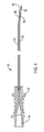
以下、図3、図5、図6A、図6Bおよび図7Bを参照して、電極66について説明する。電極66は、プラスチックまたは電気絶縁材料から形成されたハブ68を有している。ハブ68は、2つの互いに向き合った面70,75を有するように、形成されている。面70は、「|」として示されている第1の印72を有するように形成されている。対向するハブ面75は、「V」として示されている第2の印76を有するように形成されている。
Hereinafter, the electrode 66 will be described with reference to FIGS. 3, 5, 6A, 6B, and 7B. Electrode 66 has a
柔軟特性および弾性特性の両方を有する導電材料から形成されたチューブ状本体74が、ハブ68から前方に延在している。さらに詳細には、この材料は、その初期形状から3%以下の変形歪、場合によっては、6%以下の変形歪を受けたとき、本体が永久変形せずにその初期形状に戻るように、弾性的である。本発明の一態様では、本体74は、ニチロールとして知られているニッケルチタン合金から形成されている。本体74は、電極66がカニューレ42内に挿入され、電極ハブ68がカニューレハブ44に当接したとき、電極本体の遠位端チップがカニューレ本体50の拡開チップ60を形成する面の少なくとも一部の前方に延在するような、全長を有している。電極本体の遠位端チップは、カニューレ本体50の最遠位端を超えて延在しないようになっている。本発明のいくつかの態様では、電極66がカニューレ42内に完全に着座したとき、電極本体の遠位端チップは、カニューレ本体50の最遠位チップから略0.4mmから1.4mmだけ後方に位置するようになっている。電極本体74は、電極本体74がカニューレ管腔54内に着座したとき、管腔54を画定するカニューレ本体50の内面と電極本体74の外面との間が一定であるように寸法決めされた外径を有している。
A
電極本体74は、曲げ部80を有するようにさらに設計されている。図5において、曲げ部80の湾曲は、説明のために誇張されている。曲げ部80は、電極66がカニューレ42内に着座したとき、電極曲げ部80がカニューレ曲げ部54によって画定されたカニューレ管腔52の区域内に着座するように、電極本体74に位置付けられている。電極66が組み立てられたとき、本体74は、本体の遠位区域82、すなわち、曲げ部80の遠位側の区域がハブ面70の方を向くようなハブ68に対する回転方位に配置されている。本体遠位区域82の遠位端が電極の66の遠位端チップであることをさらに理解されたい。
The
図6Bおよび図7Bにおいて特大点によって表わされている熱電対84が、電極本体74内に配置されている。熱電対84は、本体遠位区域82内に配置されている。(図示されない)絶縁ワイヤが、熱電対84から電極本体75を通ってハブ68に延在している。熱電対84および熱電対に延在する導体の構造は、本発明の一部をなすものではない。
A
ケーブル92(図1)が、電極ハブ68から近位側に延在している。 ケーブル92は、ハブを通って電極本体74に接続されたワイヤを含んでいる。ケーブ92内には、電極本体74内のワイヤに接続され、熱電対84に接続されたワイヤも設けられている。ケーブル92の近位端は、制御コンソール36に接続されている。
A cable 92 (FIG. 1) extends proximally from the
制御コンソール36は、可変電流を電極アセンブリ32に供給することができる電源(図示せず)を備えている。接地パッド34は、電源に対する戻り導体端末として機能するものである。典型的には、電流は、AC電流である。制御コンソール36は、施術者が供給される電流の周波数、電流レベル、および電圧レベルを調整することを可能にするように構成されている。制御コンソール36の具体的な構造は、本発明の一部をなすものではない。本発明のシステム30の制御コンソール36として用いることができる制御コンソールの特徴は、2005年12月1日に公開された「電気外科手術手順に用いられる電気刺激および高周波出力を制御するためのシステムおよび方法」と題する米国特許出願公開第2005/0267553号および2007年1月18日に公開された「バイポーラ能動チップおよび独立した供給電極を有するカニューレを備える医療用バイポーラ電極アセンブリ、およびモノポーラ能動チップおよび独立した温度変換ポストを有するカニューレを備える医療用モノポーラ電極アセンブリ」と題する米国特許出願公開第2007/0016185号に開示されている。これらの文献は、参照することによってここに含まれるものとする。
The
本発明の電気外科手術システム30は、接地パッド34を患者に付着させることによって、使用の準備が整えられることになる。ケーブル35は、接地パッド34を制御コンソール36に接続するものである。
The
カニューレ42が、患者の焼灼プロセスを受ける皮下組織に隣接する箇所に挿入される。挿入プロセスにおいて、カニューレの拡開した遠位端チップ60は、皮膚を突き刺す電極アセンブリ32の一部である。このステップにおいて、電極66は、カニューレ42に装着されていない。代わって、柔軟な針状物(図示せず)がカニューレ管腔52内に着座されている。針状物は、カニューレ本体50がカニューレの永久変形をもたらさす程度まで曲がるのを阻止するものである。
A cannula 42 is inserted adjacent to the subcutaneous tissue undergoing the patient's cauterization process. In the insertion process, the expanded distal tip 60 of the cannula is part of the electrode assembly 32 that pierces the skin. In this step, the electrode 66 is not attached to the cannula 42. Instead, a flexible needle (not shown) is seated within the cannula lumen 52. The needles prevent the
施術者は、カニューレ42が目標組織の近傍に位置するように、カニューレ42を誘導する。目標組織は、焼灼手順を受けるべき箇所である。カニューレ本体50の比較的小さい直径に起因して、カニューレは、比較的柔軟である。この柔軟性によって、施術者は、カニューレを容易に目標組織の近傍に誘導することができる。この誘導プロセスの一部として、施術者は、カニューレが焼灼されるべき組織に対する適切な回転方位にあるように、カニューレを位置決めする。カニューレが適切に位置決めされた時点で、針状物が取り外される。
The practitioner guides the cannula 42 so that the cannula 42 is located near the target tissue. The target organization is the place that should undergo the cautery procedure. Due to the relatively small diameter of the
次いで、施術者は、電極66をカニューレ42内に挿入する。もし特定の手術手順がアセンブリ32の遠位端に隣接する小さな体積の組織内に電流を供給することしか要求しないなら、電極は、図6Bに示されているように、電極本体74の遠位区域82をカニューレ本体の遠位区域56内に位置決めするように、着座される。施術者は、カニューレ曲げ部54および電極曲げ部80がそれぞれ同じ方向に延出するように、カニューレ本体50内の電極本体74の回転方位を設定することによって、電極をこのように着座させることができる。施術者は、図6Aに示されているように、ハブ68がカニューレハブ42に向かって移動するときに、電極印72がカニューレ印43の方を向くように、電極ハブ68を位置合わせすることによって、電極のこの配向を設定することができる。
The practitioner then inserts electrode 66 into cannula 42. If a particular surgical procedure requires only supplying current into a small volume of tissue adjacent to the distal end of assembly 32, the electrode may be distal to
電極66がこのように配向された結果として、電極本体の遠位区域82がカニューレ曲げ部54に接近したとき、電極曲げ部80が電極遠位区域82をカニューレ本体遠位区域56内に湾曲させることになる。この挿入プロセスの最後に、電極本体74の遠位端チップは、図6Bに示されているように、カニューレ管腔52の最遠位部の内側に着座することになる。アセンブリ50がこの形態にあるとき、電流は、1つのみの能動チップ、すなわち、カニューレ本体50の絶縁されていない部分、具体的には、曲げ部54および遠位区域56からのみ供給されることになる。
As a result of the electrode 66 being oriented in this manner, the electrode bend 80 causes the electrode
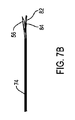
代替的に、施術者は、アセンブリ32の遠位端に隣接する比較的大きい体積の組織内に電流を流すことを望むことがある。この種の手順を行なうために、施術者は、遠位区域82がカニューレ本体の側開口58から外に延出するように、電極66を着座させることになる。電極66は、カニューレ近位区域の長軸に沿って、電極曲げ部80がカニューレ曲げ部54の方位と反対の方位を有するように、カニューレ内の電極本体を配向させることによって、このように位置決めされる。電極66は、図7Aに示されているように、電極印76がカニューレ印43と並んで位置するように電極を回転させることによって、このように配向される。いったん電極66がこのように配向されたなら、電気本体74がカニューレ管腔52内に前進される。最終的に、電極本体74の遠位端チップは、カニューレ側開口58に到達する。電極本体74を形成する材料の弾性特性に起因して、曲げ部80内に蓄積されたポテンシャルエネルギーが開放される。このエネルギーによって、本体遠位区域82が、カニューレ本体側開口58から外に押し出されることになる。電極がカニューレ内に完全に着座したとき、電極本体74の遠位区域82は、図2、図3および図7Bに示されているように、カニューレ遠位区域56の外側で該カニューレ遠位区域56に隣接して位置することになる。
Alternatively, the practitioner may desire to pass current through a relatively large volume of tissue adjacent to the distal end of assembly 32. To perform this type of procedure, the practitioner will seat the electrode 66 such that the
図7Bに示されているようなアセンブリを通して電流が供給されると、該電流は、2つの能動チップ、すなわち、カニューレ本体の露出した曲げ部および遠位区域と電極本体の露出した遠位区域82とを通して供給される。従って、電流は、アセンブリが単一能動チップから電流を供給するように構成されたときよりもカニューレにごく隣接する大きな体積の組織を通って流れることになる。
When current is supplied through the assembly as shown in FIG. 7B, the current is divided into two active tips: the exposed bend and distal section of the cannula body and the exposed
従って、このアセンブリのカニューレおよび電極は、2つのモードの1つ、すなわち、アセンブリが電流を単一の能動チップから供給するモードまたはアセンブリが電流を複数の能動チップから供給するモードによって操作するように構成することができることになる。したがって、施術者は、アセンブリの操作モードを設定することによって、電流をアセンブリ32に隣接する比較的小さい体積の組織または比較的大きな体積の組織のいずれに流すかを設定することができる。 Thus, the cannula and electrodes of this assembly are operated in one of two modes: the mode in which the assembly supplies current from a single active chip or the mode in which the assembly supplies current from multiple active chips. Can be configured. Thus, the practitioner can set whether the current flows through a relatively small volume tissue or a relatively large volume tissue adjacent to the assembly 32 by setting the mode of operation of the assembly.
さらに、操作モードに関わりなく、電極66は、典型的にはカニューレ42内に完全に着座している。その結果、操作モードに関わりなく、熱電対84は、電流が流れる組織から本質的に同じ距離を隔てて離間している。組織からカニューレ本体50の電極遠位区域56までの熱電対の離間距離が最小になる。従って、いずれの操作モードにおいても、組織温度を表す熱電対84から出力される信号は、同程度の精度で組織の実温度を表すことになる。これは、有用である。何故なら、施術者は、組織を特定の温度に確実に加熱する電流を該組織に印加するように、制御コンソールを設定することを望むからである。システム30がこのように構成されたとき、制御コンソール36は、熱電対からの出力信号を組織温度を表す信号として用いることができる。
Further, regardless of the mode of operation, the electrode 66 is typically fully seated within the cannula 42. As a result, regardless of the mode of operation, the
本発明のさらなる特徴は、カニューレ42が患者内に挿入された時点で、施術者がアセンブリ32の操作モードを再設定することができる点にある。例えば、施術者は、単一の能動チップ、すなわち、カニューレ本体遠位区域56のみから電流を供給することによって、手術手順を開始する。次いで、施術者は、電流が両方のチップ、すなわち、カニューレ本体遠位区域および電極本体遠位区域から供給されるように、アセンブリを再設定することができる。施術者は、まず電極本体74をカニューレ管腔52から部分的に引き込むことによって、この切換を行なうことになる。次いで、電極印76がカニューレ印43と真っ直ぐに並ぶように、電極66を回転させる。次いで、電極本体74をカニューレ管腔52内に完全に再挿入する。電極本体74のこの回転および再挿入によって、電気本体遠位区域が、カニューレ本体側開口58から外に延出することになる。このようにして、アセンブリは、電流が2つの能動チップから供給されるモードによって操作する準備が整ったことになる。
A further feature of the present invention is that the practitioner can reset the operating mode of the assembly 32 once the cannula 42 is inserted into the patient. For example, the practitioner initiates the surgical procedure by supplying current only from a single active tip, ie, cannula body
前述した方法と逆の方法を用いて、いったん患者に装着されたアセンブリ32を複数の能動チップによる操作モードから単一の能動チップによる操作モードに切り換えることもできる。 The assembly 32 once attached to the patient can be switched from a plurality of active chip operation modes to a single active chip operation mode using a method opposite to that described above.
前述の説明は、本発明の1つの特定の態様に向けられている。前述した特徴と異なる特徴を有する本発明の他の態様も可能である。 The foregoing description is directed to one specific aspect of the present invention. Other aspects of the present invention are possible that have features different from those described above.
例えば、本発明の全ての態様において、必ずしも、熱電対が、温度を表す信号を供給するために電極内に配置される構成要素である必要がない。熱抵抗器または他の温度検知変換器がこの機能を果たすようになっていてもよい。 For example, in all aspects of the invention, the thermocouple need not necessarily be a component placed in the electrode to provide a signal representative of temperature. A thermal resistor or other temperature sensing transducer may be adapted to perform this function.
同様に、本発明の全ての態様において、必ずしも、カニューレ本体または電極本体のいずれもが単一の材料区分から形成された構成要素である必要がない。例えば、カニューレ本体は、非導電性プラスチックから形成された近位区域を備えていてもよい。この場合、曲げ部および遠位区域は、金属または他の導電性材料から形成されているとよい。 Similarly, in all aspects of the invention, it is not necessary for either the cannula body or the electrode body to be a component formed from a single material section. For example, the cannula body may include a proximal section formed from a non-conductive plastic. In this case, the bend and the distal section may be formed from metal or other conductive material.
さらに、前述のカニューレは、所謂、モノポーラカニューレである。このカニューレは、単一の導電面を有している。本発明の代替的態様では、カニューレは、バイポーラカニューレであってもよい。この種のカニューレは、互いに電気的に絶縁された2つの導電面を有している。本発明のこの態様のアセンブリを用いて、所謂、バイポーラアブレーション手術手順を行なうことができる。カニューレの第2の導電面は、戻り導電端末として機能する。 Furthermore, the aforementioned cannula is a so-called monopolar cannula. The cannula has a single conductive surface. In an alternative aspect of the invention, the cannula may be a bipolar cannula. This type of cannula has two conductive surfaces that are electrically isolated from each other. The assembly of this aspect of the invention can be used to perform a so-called bipolar ablation surgical procedure. The second conductive surface of the cannula functions as a return conductive terminal.
本発明のこの態様では、アセンブリが複数の能動チップによるモードで操作されるとき、電極66の露出した遠位区域82とカニューレの露出した区域の1つとが1対の共通能動チップを形成することになる。カニューレの第2の露出した区域は、戻り導電端末として機能する。
In this aspect of the invention, when the assembly is operated in a mode with multiple active tips, the exposed
同様に、電極本体は、互いに異なる材料の複数の区域から形成されていてもよい。例えば、電極本体は、弾性プラスチックから形成された近位区域を有していてもよい。電極本体のこのプラスチック部分は、柔軟な曲げ部を有するように形成されているとよい。曲げ部の遠位側において、電極は、比較的非柔軟性の導体から形成されたチップを有しているとよい。この態様の利点は、アセンブリが複数の能動チップによるモードで操作され、該電極がカニューレ側開口から外に展開するとき、露出した比較的非柔軟性の遠位端が、破損しにくい点にある。 Similarly, the electrode body may be formed from a plurality of areas of different materials. For example, the electrode body may have a proximal section formed from an elastic plastic. This plastic part of the electrode body may be formed to have a flexible bend. On the distal side of the bend, the electrode may have a tip formed from a relatively inflexible conductor. The advantage of this embodiment is that the exposed relatively inflexible distal end is less prone to breakage when the assembly is operated in a mode with multiple active tips and the electrode is deployed out of the cannula side opening. .
さらに、本発明は、所謂、モノポーラ手術手順、すなわち、接地パッドが戻り電極として機能する手術手順においてのみ用いられることに制限されるものではない。本発明のアセンブリ32は、所謂、パラレルバイポーラ焼灼手順を行なうために用いられてもよい。この種の手順では、2つのカニューレ/電極アセンブリが、患者内に挿入される。これらのアセンブリは、電流が流れるべき組織の両側に位置決めされる。この種の手順では、第2のカニューレ/電極アセンブリが、所謂、戻り電極として機能する。 Furthermore, the present invention is not limited to being used only in so-called monopolar surgical procedures, i.e. surgical procedures in which the ground pad functions as a return electrode. The assembly 32 of the present invention may be used to perform a so-called parallel bipolar ablation procedure. In this type of procedure, two cannula / electrode assemblies are inserted into the patient. These assemblies are positioned on both sides of the tissue through which current is to flow. In this type of procedure, the second cannula / electrode assembly functions as a so-called return electrode.
この種の手術手順において、必ずしも、両方のカニューレ/電極アセンブリが本発明の形式である必要がない。この種の手術手順において、本発明のアセンブリ32は、電極遠位区域82が電流の流されるべき組織の方を向くように電極曲げ部80が位置決めされて配向されることが推奨される。この推奨は、アセンブリ32が単一チップによるモードまたは複数の能動チップによるモードのいずれによって操作されるときにも適用される。電極66のこの配向は、熱電対84が電流の流されるべき組織に比較的接近して配置されることを確実にするために提案されている。これによって、熱電対が電流の流されるべき組織の温度を可能な限り厳密に表す信号を出力する程度が向上することになる。
In this type of surgical procedure, it is not necessary for both cannula / electrode assemblies to be of the form of the present invention. In this type of surgical procedure, the assembly 32 of the present invention is recommended to have the electrode bend 80 positioned and oriented so that the electrode
図8は、本発明の代替的電極102を示している。電極102は、最初に述べた電極66と同じ特徴を有している。電極102は、電極本体74を覆って配置された電気絶縁材料から形成されたスリーブ104をさらに備えている。スリーブ104は、ハブ68から曲げ部80の前方の位置まで遠位側に延在している。図8において、スリーブ104の肉厚は、説明のために誇張されている。
FIG. 8 illustrates an
図8の電極は、別の一組の導体がカニューレハブ44から制御コンソール36に延在する本発明の態様において用いられる。これらの導体(図示せず)は、制御コンソール36とカニューレ本体50との間に電気接続をもたらすものである。
The electrode of FIG. 8 is used in aspects of the present invention in which another set of conductors extends from
従って、本発明のこのカニューレ/電極アセンブリは、モノポーラユニットまたは独立したバイポーラユニットのいずれかとして操作することができる。このアセンブリは、電極本体の遠位区域82がカニューレ本体の遠位区域56内に着座するように電極102をカニューレ44内に着座させることによって、モノポーラユニットとして作動されることになる。アセンブリがこの状態で作動されるとき、電極102を制御コンソール36に接続するのみでよい。この状態のアセンブリは、単一能動チップ、すなわち、電極遠位区域82の絶縁されていない部分によって作動することになる。接地パッド45は、戻り端末として機能する。
Thus, the cannula / electrode assembly of the present invention can be operated as either a monopolar unit or an independent bipolar unit. This assembly will be operated as a monopolar unit by seating the
代替的に、施術者は、このアセンブリを独立したバイポーラユニットとして操作することを望むことがある。この場合、アセンブリは、電極本体がカニューレ管腔52内に挿入されるとき、電極本体の遠位区域がカニューレ側開口58から外に突出すべく電極102を配向させるように構成されるとよい。電極102がこのように位置決めされたとき、スリーブ104の最遠位部分もカニューレ側開口58から外に突出することを理解されたい。従って、アセンブリがこのように構成されたとき、カニューレ本体の遠位区域56と電極本体の遠位区域82とは、互いに電気的に絶縁されている。この構成のアセンブリを操作するために、カニューレハブ44から延在するケーブルを制御コンソール36に接続することがさらに必要である。
Alternatively, the practitioner may wish to operate this assembly as an independent bipolar unit. In this case, the assembly may be configured to orient the
この構成のアセンブリを操作するために、電流がコンソール電源からカニューレを通って流される。能動チップの1つである露出したカニューレ本体遠位区域56は、能動チップとして機能する。露出した電極本体遠位区域82は、戻り端末として機能する。露出した電極本体遠位区域82は、戻り端末として機能する。本発明のアセンブリをこのように構成することによって、施術者は、必要に応じて、露出したチップを包囲する小さい体積の組織内に電流を流すことができる。
To operate the assembly in this configuration, current is passed through the cannula from the console power supply. The exposed cannula body
管腔52を画定する本体の内壁の周りに延在するライナーを有するカニューレを設けることによって、本発明のこの態様の代替的実施形態を構成することができる。このライナーも、側開口52を画定するカニューレの外面を覆っている。 By providing a cannula having a liner that extends around the inner wall of the body that defines the lumen 52, alternative embodiments of this aspect of the invention can be constructed. This liner also covers the outer surface of the cannula defining the side opening 52.
従って、添付の請求項の目的は、本発明の真の精神および範囲内に含まれるこのような修正および変更の全てを包含することにある。
Accordingly, it is the object of the appended claims to cover all such modifications and changes as fall within the true spirit and scope of the invention.
Claims (26)
ケーブルに接続されるように構成された電極であって、前記ケーブルは、前記電極を制御コンソールに接続するようになっており、前記電極は、前記カニューレ本体の前記管腔内に着座するように寸法決めされた電極本体を有しており、前記電極本体は、前記ケーブル内の導体に電気的に接続された導電材料から形成された遠位区域と、前記遠位区域の近位側に位置する弾性材料から形成された区域と、を有している、電極と、
を備えるカニューレ/電極アセンブリにおいて、
前記電極本体が前記カニューレの前記管腔内に挿入されたときに、弾性材料から形成された前記区域が、前記曲げ部によって画定された前記管腔の区域内に収まるように位置付けされ、弾性材料から形成された前記区域が曲げ部を画定するように形成されており、これによって、前記カニューレ本体に対する前記電極本体の回転方位に依存して、前記電極本体が前記カニューレ本体内に挿入されたとき、前記電極本体の前記遠位区域は、前記カニューレ本体の前記遠位区域内の前記管腔の前記区域内に着座するか、または前記カニューレ本体側開口から外に延出するようになっていることを特徴とする、カニューレ/電極アセンブリ。 A cannula having a cannula body, said cannula body having a proximal end and a distal end facing each other, a distal section of the conductive distal regions defining the distal end of the cannula body When the proximal end of the cannula body so as to extend in the a bend located proximally of the distal section, the distal end of the cannula body through the bending portion of the cannula body through a lumen that extends distally along the longitudinal direction, a portion of said cannula body defining an outer portion of the spaced and the bent portion proximally from said distal end of said cannula body from a side opening is an incision in the lumen of the cannula body, the cannula having a side opening,
A electrode configured to be connected to the cable, the cable is adapted to connect the electrodes to the control console, the electrode, as seated in the tube lumen of the cannula body has sized the electrode body, the electrode body has a distal section that is formed from electrically connected to the conductive material in the conductor in the cable, located on the proximal side of the distal section has a region which is formed of an elastic material, and an electrode,
Oite the cannula / electrode assembly comprising,
When the front Symbol electrode body is inserted into said lumen of said cannula, said areas formed of an elastic material, is positioned to fit within the area of the lumen thus defined in the bent portion, is formed so as to define said Ward gamut bent portion formed from an elastic material, by which, depending on the rotational orientation of the electrode body against the cannula body, the electrode body the cannula body when inserted, the distal section of the electrode body, or seated in the zone of the lumen in the distal section of the cannula body, or the cannula body side opening or al outside the extension A cannula / electrode assembly, characterized in that
前記カニューレ本体の前記近位端は、前記ハブに取り付けられており、前記カニューレ本体は、前記ハブから遠位側に延在しており、
前記カニューレの前記印は、前記カニューレの前記ハブ上に配置されていることを特徴とする、請求項2に記載のカニューレ/電極アセンブリ。 The cannula has a hub;
The proximal end of the cannula body is attached to the hub, the cannula body extending distally from the hub;
The cannula / electrode assembly according to claim 2, wherein the indicia of the cannula is disposed on the hub of the cannula.
前記電極本体は、前記電極の前記ハブから延在しており、
前記電極の前記印は、前記電極の前記ハブ上に配置されていることを特徴とする、請求項2または3に記載のカニューレ/電極アセンブリ。 The electrode has a hub, and the hub is a component of the electrode to which the cable is connected;
The electrode body is extended from the hub of the electrode,
Said indicia of said electrodes, characterized in that it is arranged on the hub of the electrode, cannula / electrode assembly according to claim 2 or 3.
前記カニューレ本体の前記近位端は、前記ハブに取り付けられており、前記カニューレ本体は、前記ハブから遠位側に延在していることを特徴とする、請求項1〜12のいずれか1つに記載のカニューレ/電極アセンブリ。 Wherein the cannula has a hub,
Said proximal end of said cannula body, said mounted on the hub, the cannula body, characterized in that it extends distally from said hub, any one of claims 1 to 12 A cannula / electrode assembly according to claim 1.
前記電極本体は、前記電極の前記ハブから延在していることを特徴とする、請求項1〜13のいずれか1つに記載のカニューレ/電極アセンブリ。 The electrode has a hub, the hub being a component of the electrode to which the cable is connected;
The electrode body is characterized in that extending from the hub of the electrode, cannula / electrode assembly according to any one of claims 1 to 13.
互いに向き合った近位端および遠位端と、
導電性の遠位区域であって、前記カニューレ本体の前記遠位端を画定する遠位区域と、
前記カニューレ本体の前記遠位区域の近位側に位置する曲げ部と、
前記カニューレ本体の前記近位端から長手方向に沿って遠位側に延在する管腔であって、前記曲げ部を貫通して前記カニューレ本体の前記遠位端に延在し、かつ、前記電極の前記本体を受け入れるように、寸法決めされている、管腔と、
前記カニューレ本体から前記管腔へ内方に延在する側開口であって、前記曲げ部の外側部分を画定する前記カニューレ本体の部分を貫通し、かつ、前記電極本体の遠位区域が貫通できるように寸法決めされている、側開口とを備え、
前記カニューレ本体は、代替的に、前記電極本体の前記遠位区域が、前記側開口の遠位側に位置する前記カニューレ本体の前記管腔の部分内へと延在し得るように、さらに形成されていることを特徴とする、カニューレ。 A cannula used as part of a cannula / electrode assembly according to any one of claims 1 to 16 , comprising a cannula body, the cannula body comprising
A proximal end and a distal end facing each other;
A conductive distal section that defines the distal end of the cannula body;
A bend located on the proximal side of the distal section of the cannula body;
A lumen extending longitudinally distally from the proximal end of the cannula body, extending through the bend to the distal end of the cannula body, and A lumen dimensioned to receive the body of electrodes;
A side opening extending inwardly from the cannula body to the lumen, through a portion of the cannula body that defines an outer portion of the bend and through a distal section of the electrode body With side openings that are dimensioned to
The cannula body may alternatively be further configured such that the distal section of the electrode body can extend into the lumen portion of the cannula body located distal to the side opening. A cannula, characterized in that
前記カニューレの前記印が、前記カニューレの前記ハブ上に配置されていることを特徴とする、請求項18に記載のカニューレ。The cannula of claim 18, wherein the indicia of the cannula are disposed on the hub of the cannula.
Applications Claiming Priority (1)
| Application Number | Priority Date | Filing Date | Title |
|---|---|---|---|
| PCT/US2013/027038 WO2014130031A1 (en) | 2013-02-21 | 2013-02-21 | Tissue ablation cannula and electrode assembly that can be selectively operated with one or more active tips |
Publications (3)
| Publication Number | Publication Date |
|---|---|
| JP2016507341A JP2016507341A (en) | 2016-03-10 |
| JP2016507341A5 JP2016507341A5 (en) | 2016-04-21 |
| JP6153632B2 true JP6153632B2 (en) | 2017-06-28 |
Family
ID=47843426
Family Applications (1)
| Application Number | Title | Priority Date | Filing Date |
|---|---|---|---|
| JP2015559217A Active JP6153632B2 (en) | 2013-02-21 | 2013-02-21 | Tissue ablation cannula / electrode assembly selectively operable by one or more active tips |
Country Status (6)
| Country | Link |
|---|---|
| EP (2) | EP2958503B1 (en) |
| JP (1) | JP6153632B2 (en) |
| AU (2) | AU2013378829B2 (en) |
| CA (1) | CA2901383A1 (en) |
| ES (2) | ES2681970T3 (en) |
| WO (1) | WO2014130031A1 (en) |
Families Citing this family (3)
| Publication number | Priority date | Publication date | Assignee | Title |
|---|---|---|---|---|
| WO2015095254A1 (en) | 2013-12-18 | 2015-06-25 | Stryker Corporation | Assembly for sequentially percutaneously applying an electrode and an anesthetic to tissue |
| US10675085B2 (en) | 2015-11-23 | 2020-06-09 | Boston Scientific Scimed, Inc. | Devices and methods for enhanced denervation procedures |
| WO2021086817A1 (en) * | 2019-10-28 | 2021-05-06 | Boston Scientific Neuromodulation Corporation | Rf electrode cannula |
Family Cites Families (11)
| Publication number | Priority date | Publication date | Assignee | Title |
|---|---|---|---|---|
| DE3922406C1 (en) * | 1989-07-07 | 1990-10-11 | B. Braun Melsungen Ag, 3508 Melsungen, De | |
| US5672173A (en) * | 1995-08-15 | 1997-09-30 | Rita Medical Systems, Inc. | Multiple antenna ablation apparatus and method |
| US6302880B1 (en) * | 1996-04-08 | 2001-10-16 | Cardima, Inc. | Linear ablation assembly |
| EP1056403B1 (en) * | 1998-02-19 | 2005-01-19 | Curon Medical, Inc. | Electrosurgical sphincter treatment apparatus |
| US20050277918A1 (en) * | 2003-03-07 | 2005-12-15 | Baylis Medical Company Inc. | Electrosurgical cannula |
| US8361067B2 (en) * | 2002-09-30 | 2013-01-29 | Relievant Medsystems, Inc. | Methods of therapeutically heating a vertebral body to treat back pain |
| US20050267553A1 (en) | 2004-05-05 | 2005-12-01 | Doug Staunton | System and method for controlling electrical stimulation and radiofrequency output for use in an electrosurgical procedure |
| DE602006012469D1 (en) | 2005-04-29 | 2010-04-08 | Stryker Corp | BIPOLAR MEDICAL ELECTRODE ARRANGEMENT WITH CANNULA AND REMOVABLE CONNECTOR ELECTRODE |
| US9357977B2 (en) * | 2006-01-12 | 2016-06-07 | Gynesonics, Inc. | Interventional deployment and imaging system |
| US20090105775A1 (en) * | 2007-10-19 | 2009-04-23 | David Mitchell | Cannula with lateral access and directional exit port |
| KR101632429B1 (en) * | 2010-05-21 | 2016-06-21 | 님버스 컨셉츠, 엘엘씨 | Systems and methods for tissue ablation |
-
2013
- 2013-02-21 CA CA2901383A patent/CA2901383A1/en active Pending
- 2013-02-21 AU AU2013378829A patent/AU2013378829B2/en active Active
- 2013-02-21 WO PCT/US2013/027038 patent/WO2014130031A1/en active Application Filing
- 2013-02-21 ES ES13708310.1T patent/ES2681970T3/en active Active
- 2013-02-21 ES ES18165810T patent/ES2770850T3/en active Active
- 2013-02-21 JP JP2015559217A patent/JP6153632B2/en active Active
- 2013-02-21 EP EP13708310.1A patent/EP2958503B1/en active Active
- 2013-02-21 EP EP18165810.5A patent/EP3360500B1/en active Active
-
2018
- 2018-07-19 AU AU2018206803A patent/AU2018206803B2/en active Active
Also Published As
| Publication number | Publication date |
|---|---|
| JP2016507341A (en) | 2016-03-10 |
| ES2770850T3 (en) | 2020-07-03 |
| AU2013378829A1 (en) | 2015-09-10 |
| WO2014130031A1 (en) | 2014-08-28 |
| CA2901383A1 (en) | 2014-08-28 |
| EP3360500A1 (en) | 2018-08-15 |
| ES2681970T3 (en) | 2018-09-17 |
| AU2018206803B2 (en) | 2020-05-28 |
| EP2958503B1 (en) | 2018-07-04 |
| EP2958503A1 (en) | 2015-12-30 |
| EP3360500B1 (en) | 2020-01-08 |
| AU2013378829B2 (en) | 2018-04-19 |
| AU2018206803A1 (en) | 2018-08-09 |
Similar Documents
| Publication | Publication Date | Title |
|---|---|---|
| US7115124B1 (en) | Device and method for tissue ablation using bipolar radio-frequency current | |
| EP2760358B1 (en) | Electrosurgical device with offset conductive element | |
| US20050059964A1 (en) | Enhancing the effectiveness of medial branch nerve root RF neurotomy | |
| US20230000544A1 (en) | Tissue Ablation Cannula Assembly | |
| US20100125250A1 (en) | Medical needles and electrodes with improved bending stiffness | |
| US20220218412A1 (en) | Mapping and ablation catheter with multiple loop segments | |
| US20060247615A1 (en) | Multi-element bi-polar ablation electrode | |
| AU2018206803B2 (en) | Cannula for tissue ablation | |
| US20150196350A1 (en) | Electrosurgical devices having enhanced effectiveness and methods of making and using same | |
| EP4215138A1 (en) | Systems and methods for a single spiral electrode assembly forming a spherical basket for improved tissue contact and current delivery | |
| US20230075838A1 (en) | Basket Catheter with Mushroom Shape Distal Tip | |
| EP4215142A1 (en) | Systems and methods for tripodic spines forming a spherical basket for improved tissue contact and current delivery | |
| EP4215145A1 (en) | Systems and methods for c-shaped spines forming a spherical basket for improved tissue contact and current delivery | |
| EP4215141A2 (en) | Systems and methods for linear spines forming a spherical basket for improved tissue contact and current delivery | |
| CN116458989A (en) | Systems and methods for forming single spiral electrode assemblies of spherical baskets for improved tissue contact and current delivery | |
| CN117838296A (en) | Probe with distal cutting electrode | |
| CN116458988A (en) | System and method for forming C-shaped ridges of spherical basket for improved tissue contact and current delivery |
Legal Events
| Date | Code | Title | Description |
|---|---|---|---|
| A521 | Request for written amendment filed |
Free format text: JAPANESE INTERMEDIATE CODE: A523 Effective date: 20160208 |
|
| A621 | Written request for application examination |
Free format text: JAPANESE INTERMEDIATE CODE: A621 Effective date: 20160208 |
|
| A977 | Report on retrieval |
Free format text: JAPANESE INTERMEDIATE CODE: A971007 Effective date: 20161208 |
|
| A131 | Notification of reasons for refusal |
Free format text: JAPANESE INTERMEDIATE CODE: A131 Effective date: 20161216 |
|
| A521 | Request for written amendment filed |
Free format text: JAPANESE INTERMEDIATE CODE: A523 Effective date: 20170310 |
|
| TRDD | Decision of grant or rejection written | ||
| A01 | Written decision to grant a patent or to grant a registration (utility model) |
Free format text: JAPANESE INTERMEDIATE CODE: A01 Effective date: 20170331 |
|
| A601 | Written request for extension of time |
Free format text: JAPANESE INTERMEDIATE CODE: A601 Effective date: 20170425 |
|
| R155 | Notification before disposition of declining of application |
Free format text: JAPANESE INTERMEDIATE CODE: R155 |
|
| A61 | First payment of annual fees (during grant procedure) |
Free format text: JAPANESE INTERMEDIATE CODE: A61 Effective date: 20170530 |
|
| R150 | Certificate of patent or registration of utility model |
Ref document number: 6153632 Country of ref document: JP Free format text: JAPANESE INTERMEDIATE CODE: R150 |
|
| R250 | Receipt of annual fees |
Free format text: JAPANESE INTERMEDIATE CODE: R250 |
|
| R250 | Receipt of annual fees |
Free format text: JAPANESE INTERMEDIATE CODE: R250 |
|
| R250 | Receipt of annual fees |
Free format text: JAPANESE INTERMEDIATE CODE: R250 |
|
| R250 | Receipt of annual fees |
Free format text: JAPANESE INTERMEDIATE CODE: R250 |