JP6149814B2 - Hybrid vehicle - Google Patents
Hybrid vehicle Download PDFInfo
- Publication number
- JP6149814B2 JP6149814B2 JP2014138790A JP2014138790A JP6149814B2 JP 6149814 B2 JP6149814 B2 JP 6149814B2 JP 2014138790 A JP2014138790 A JP 2014138790A JP 2014138790 A JP2014138790 A JP 2014138790A JP 6149814 B2 JP6149814 B2 JP 6149814B2
- Authority
- JP
- Japan
- Prior art keywords
- mode
- driving force
- vehicle
- traveling
- vehicle driving
- Prior art date
- Legal status (The legal status is an assumption and is not a legal conclusion. Google has not performed a legal analysis and makes no representation as to the accuracy of the status listed.)
- Active
Links
Images


Classifications
-
- B—PERFORMING OPERATIONS; TRANSPORTING
- B60—VEHICLES IN GENERAL
- B60W—CONJOINT CONTROL OF VEHICLE SUB-UNITS OF DIFFERENT TYPE OR DIFFERENT FUNCTION; CONTROL SYSTEMS SPECIALLY ADAPTED FOR HYBRID VEHICLES; ROAD VEHICLE DRIVE CONTROL SYSTEMS FOR PURPOSES NOT RELATED TO THE CONTROL OF A PARTICULAR SUB-UNIT
- B60W20/00—Control systems specially adapted for hybrid vehicles
- B60W20/10—Controlling the power contribution of each of the prime movers to meet required power demand
- B60W20/15—Control strategies specially adapted for achieving a particular effect
-
- B—PERFORMING OPERATIONS; TRANSPORTING
- B60—VEHICLES IN GENERAL
- B60W—CONJOINT CONTROL OF VEHICLE SUB-UNITS OF DIFFERENT TYPE OR DIFFERENT FUNCTION; CONTROL SYSTEMS SPECIALLY ADAPTED FOR HYBRID VEHICLES; ROAD VEHICLE DRIVE CONTROL SYSTEMS FOR PURPOSES NOT RELATED TO THE CONTROL OF A PARTICULAR SUB-UNIT
- B60W10/00—Conjoint control of vehicle sub-units of different type or different function
-
- B—PERFORMING OPERATIONS; TRANSPORTING
- B60—VEHICLES IN GENERAL
- B60K—ARRANGEMENT OR MOUNTING OF PROPULSION UNITS OR OF TRANSMISSIONS IN VEHICLES; ARRANGEMENT OR MOUNTING OF PLURAL DIVERSE PRIME-MOVERS IN VEHICLES; AUXILIARY DRIVES FOR VEHICLES; INSTRUMENTATION OR DASHBOARDS FOR VEHICLES; ARRANGEMENTS IN CONNECTION WITH COOLING, AIR INTAKE, GAS EXHAUST OR FUEL SUPPLY OF PROPULSION UNITS IN VEHICLES
- B60K6/00—Arrangement or mounting of plural diverse prime-movers for mutual or common propulsion, e.g. hybrid propulsion systems comprising electric motors and internal combustion engines ; Control systems therefor, i.e. systems controlling two or more prime movers, or controlling one of these prime movers and any of the transmission, drive or drive units Informative references: mechanical gearings with secondary electric drive F16H3/72; arrangements for handling mechanical energy structurally associated with the dynamo-electric machine H02K7/00; machines comprising structurally interrelated motor and generator parts H02K51/00; dynamo-electric machines not otherwise provided for in H02K see H02K99/00
- B60K6/20—Arrangement or mounting of plural diverse prime-movers for mutual or common propulsion, e.g. hybrid propulsion systems comprising electric motors and internal combustion engines ; Control systems therefor, i.e. systems controlling two or more prime movers, or controlling one of these prime movers and any of the transmission, drive or drive units Informative references: mechanical gearings with secondary electric drive F16H3/72; arrangements for handling mechanical energy structurally associated with the dynamo-electric machine H02K7/00; machines comprising structurally interrelated motor and generator parts H02K51/00; dynamo-electric machines not otherwise provided for in H02K see H02K99/00 the prime-movers consisting of electric motors and internal combustion engines, e.g. HEVs
- B60K6/42—Arrangement or mounting of plural diverse prime-movers for mutual or common propulsion, e.g. hybrid propulsion systems comprising electric motors and internal combustion engines ; Control systems therefor, i.e. systems controlling two or more prime movers, or controlling one of these prime movers and any of the transmission, drive or drive units Informative references: mechanical gearings with secondary electric drive F16H3/72; arrangements for handling mechanical energy structurally associated with the dynamo-electric machine H02K7/00; machines comprising structurally interrelated motor and generator parts H02K51/00; dynamo-electric machines not otherwise provided for in H02K see H02K99/00 the prime-movers consisting of electric motors and internal combustion engines, e.g. HEVs characterised by the architecture of the hybrid electric vehicle
- B60K6/44—Series-parallel type
- B60K6/445—Differential gearing distribution type
-
- B—PERFORMING OPERATIONS; TRANSPORTING
- B60—VEHICLES IN GENERAL
- B60K—ARRANGEMENT OR MOUNTING OF PROPULSION UNITS OR OF TRANSMISSIONS IN VEHICLES; ARRANGEMENT OR MOUNTING OF PLURAL DIVERSE PRIME-MOVERS IN VEHICLES; AUXILIARY DRIVES FOR VEHICLES; INSTRUMENTATION OR DASHBOARDS FOR VEHICLES; ARRANGEMENTS IN CONNECTION WITH COOLING, AIR INTAKE, GAS EXHAUST OR FUEL SUPPLY OF PROPULSION UNITS IN VEHICLES
- B60K6/00—Arrangement or mounting of plural diverse prime-movers for mutual or common propulsion, e.g. hybrid propulsion systems comprising electric motors and internal combustion engines ; Control systems therefor, i.e. systems controlling two or more prime movers, or controlling one of these prime movers and any of the transmission, drive or drive units Informative references: mechanical gearings with secondary electric drive F16H3/72; arrangements for handling mechanical energy structurally associated with the dynamo-electric machine H02K7/00; machines comprising structurally interrelated motor and generator parts H02K51/00; dynamo-electric machines not otherwise provided for in H02K see H02K99/00
- B60K6/20—Arrangement or mounting of plural diverse prime-movers for mutual or common propulsion, e.g. hybrid propulsion systems comprising electric motors and internal combustion engines ; Control systems therefor, i.e. systems controlling two or more prime movers, or controlling one of these prime movers and any of the transmission, drive or drive units Informative references: mechanical gearings with secondary electric drive F16H3/72; arrangements for handling mechanical energy structurally associated with the dynamo-electric machine H02K7/00; machines comprising structurally interrelated motor and generator parts H02K51/00; dynamo-electric machines not otherwise provided for in H02K see H02K99/00 the prime-movers consisting of electric motors and internal combustion engines, e.g. HEVs
- B60K6/42—Arrangement or mounting of plural diverse prime-movers for mutual or common propulsion, e.g. hybrid propulsion systems comprising electric motors and internal combustion engines ; Control systems therefor, i.e. systems controlling two or more prime movers, or controlling one of these prime movers and any of the transmission, drive or drive units Informative references: mechanical gearings with secondary electric drive F16H3/72; arrangements for handling mechanical energy structurally associated with the dynamo-electric machine H02K7/00; machines comprising structurally interrelated motor and generator parts H02K51/00; dynamo-electric machines not otherwise provided for in H02K see H02K99/00 the prime-movers consisting of electric motors and internal combustion engines, e.g. HEVs characterised by the architecture of the hybrid electric vehicle
- B60K6/48—Parallel type
-
- B—PERFORMING OPERATIONS; TRANSPORTING
- B60—VEHICLES IN GENERAL
- B60W—CONJOINT CONTROL OF VEHICLE SUB-UNITS OF DIFFERENT TYPE OR DIFFERENT FUNCTION; CONTROL SYSTEMS SPECIALLY ADAPTED FOR HYBRID VEHICLES; ROAD VEHICLE DRIVE CONTROL SYSTEMS FOR PURPOSES NOT RELATED TO THE CONTROL OF A PARTICULAR SUB-UNIT
- B60W10/00—Conjoint control of vehicle sub-units of different type or different function
- B60W10/04—Conjoint control of vehicle sub-units of different type or different function including control of propulsion units
- B60W10/08—Conjoint control of vehicle sub-units of different type or different function including control of propulsion units including control of electric propulsion units, e.g. motors or generators
-
- B—PERFORMING OPERATIONS; TRANSPORTING
- B60—VEHICLES IN GENERAL
- B60W—CONJOINT CONTROL OF VEHICLE SUB-UNITS OF DIFFERENT TYPE OR DIFFERENT FUNCTION; CONTROL SYSTEMS SPECIALLY ADAPTED FOR HYBRID VEHICLES; ROAD VEHICLE DRIVE CONTROL SYSTEMS FOR PURPOSES NOT RELATED TO THE CONTROL OF A PARTICULAR SUB-UNIT
- B60W20/00—Control systems specially adapted for hybrid vehicles
-
- B—PERFORMING OPERATIONS; TRANSPORTING
- B60—VEHICLES IN GENERAL
- B60W—CONJOINT CONTROL OF VEHICLE SUB-UNITS OF DIFFERENT TYPE OR DIFFERENT FUNCTION; CONTROL SYSTEMS SPECIALLY ADAPTED FOR HYBRID VEHICLES; ROAD VEHICLE DRIVE CONTROL SYSTEMS FOR PURPOSES NOT RELATED TO THE CONTROL OF A PARTICULAR SUB-UNIT
- B60W2510/00—Input parameters relating to a particular sub-units
- B60W2510/24—Energy storage means
- B60W2510/242—Energy storage means for electrical energy
- B60W2510/244—Charge state
-
- Y—GENERAL TAGGING OF NEW TECHNOLOGICAL DEVELOPMENTS; GENERAL TAGGING OF CROSS-SECTIONAL TECHNOLOGIES SPANNING OVER SEVERAL SECTIONS OF THE IPC; TECHNICAL SUBJECTS COVERED BY FORMER USPC CROSS-REFERENCE ART COLLECTIONS [XRACs] AND DIGESTS
- Y02—TECHNOLOGIES OR APPLICATIONS FOR MITIGATION OR ADAPTATION AGAINST CLIMATE CHANGE
- Y02T—CLIMATE CHANGE MITIGATION TECHNOLOGIES RELATED TO TRANSPORTATION
- Y02T10/00—Road transport of goods or passengers
- Y02T10/60—Other road transportation technologies with climate change mitigation effect
- Y02T10/62—Hybrid vehicles
-
- Y—GENERAL TAGGING OF NEW TECHNOLOGICAL DEVELOPMENTS; GENERAL TAGGING OF CROSS-SECTIONAL TECHNOLOGIES SPANNING OVER SEVERAL SECTIONS OF THE IPC; TECHNICAL SUBJECTS COVERED BY FORMER USPC CROSS-REFERENCE ART COLLECTIONS [XRACs] AND DIGESTS
- Y10—TECHNICAL SUBJECTS COVERED BY FORMER USPC
- Y10S—TECHNICAL SUBJECTS COVERED BY FORMER USPC CROSS-REFERENCE ART COLLECTIONS [XRACs] AND DIGESTS
- Y10S903/00—Hybrid electric vehicles, HEVS
- Y10S903/902—Prime movers comprising electrical and internal combustion motors
- Y10S903/903—Prime movers comprising electrical and internal combustion motors having energy storing means, e.g. battery, capacitor
Landscapes
- Engineering & Computer Science (AREA)
- Transportation (AREA)
- Mechanical Engineering (AREA)
- Chemical & Material Sciences (AREA)
- Combustion & Propulsion (AREA)
- Automation & Control Theory (AREA)
- Hybrid Electric Vehicles (AREA)
- Electric Propulsion And Braking For Vehicles (AREA)
Description
この発明は、ハイブリッド車両に関し、特に、CD(Charge Depleting)モードとCS(Charge Sustaining)モードとのいずれかを選択して走行するハイブリッド車両に関する。 The present invention relates to a hybrid vehicle, and more particularly, to a hybrid vehicle that travels by selecting either a CD (Charge Depleting) mode or a CS (Charge Sustaining) mode.
入力スイッチからユーザがパワーモード又はエコノミーモードを選択可能なハイブリッド車両が知られている。このようなハイブリッド車両では、パワーモード又はエコノミーモードの選択によって、アクセル開度に対する車両駆動力(要求パワー)の特性がノーマルモードから切替えられる。エコノミーモードが選択されると、アクセル開度の増加に対する車両駆動力の増加がノーマルモードよりも緩やかになるように車両駆動力が制御される。これにより、低燃費の走行が実現される(たとえば、特許文献1参照)。 There is known a hybrid vehicle in which a user can select a power mode or an economy mode from an input switch. In such a hybrid vehicle, the characteristic of the vehicle driving force (required power) with respect to the accelerator opening is switched from the normal mode by selecting the power mode or the economy mode. When the economy mode is selected, the vehicle driving force is controlled so that the increase in the vehicle driving force with respect to the increase in the accelerator opening is more gradual than in the normal mode. Thereby, the low fuel consumption driving | running | working is implement | achieved (for example, refer patent document 1).
蓄電装置のSOC(State Of Charge)を消費するCDモードと、SOCを所定レベルに維持するCSモードとのいずれかを選択して走行するハイブリッド車両において、基本的に蓄電装置に蓄えられたエネルギーを用いて走行するCDモードでは、特に低燃費の走行が要求される。上記のようなCDモードでは、エンジンを停止させてモータを用いて走行する所謂EV走行が主体的となるが、CDモードにおいても大きな車両駆動力が要求されればエンジンが作動するので、十分な低燃費を実現できない可能性がある。上記の特許文献1では、この観点からの検討はなされていない。 In a hybrid vehicle that travels by selecting either the CD mode that consumes the SOC (State Of Charge) of the power storage device or the CS mode that maintains the SOC at a predetermined level, the energy stored in the power storage device is basically stored. In the CD mode in which the vehicle is used for driving, particularly low fuel consumption driving is required. In the CD mode as described above, the so-called EV running in which the engine is stopped and the motor is used is mainly used. However, in the CD mode, the engine is operated if a large vehicle driving force is required. There is a possibility that low fuel consumption cannot be realized. In the above-mentioned Patent Document 1, no examination is made from this viewpoint.
それゆえに、この発明の目的は、CDモードとCSモードとのいずれかを選択して走行するハイブリッド車両において、CDモードにおける燃費を向上させることである。 Therefore, an object of the present invention is to improve fuel efficiency in the CD mode in a hybrid vehicle that travels by selecting either the CD mode or the CS mode.
この発明によれば、ハイブリッド車両は、蓄電装置と、蓄電装置に蓄えられた電力を受けて車両駆動力を発生する駆動装置と、内燃機関と、制御装置とを備える。駆動装置は、さらに、内燃機関の出力を用いて蓄電装置を充電するための電力を生成可能に構成される。制御装置は、蓄電装置のSOCを消費するCDモードと、SOCを所定レベルに維持するCSモードとのいずれかを選択して走行させる。そして、制御装置は、CDモードが選択されているときは、CSモードが選択されているときよりも、同一のアクセル開度に対する車両駆動力が小さくなるように車両駆動力を制御する。 According to the present invention, a hybrid vehicle includes a power storage device, a drive device that receives power stored in the power storage device and generates vehicle driving force, an internal combustion engine, and a control device. The drive device is further configured to be able to generate electric power for charging the power storage device using the output of the internal combustion engine. The control device selects and runs either the CD mode that consumes the SOC of the power storage device or the CS mode that maintains the SOC at a predetermined level. Then, the control device controls the vehicle driving force so that the vehicle driving force with respect to the same accelerator opening is smaller when the CD mode is selected than when the CS mode is selected.
このハイブリッド車両においては、CDモードが選択されているときは、CSモードが選択されているときよりも、同一のアクセル開度に対する車両駆動力が小さいので、CDモードにおいて、車両駆動力を確保するために内燃機関を作動させる頻度が抑制される。したがって、このハイブリッド車両によれば、CDモードにおける燃費を向上させることができる。 In this hybrid vehicle, when the CD mode is selected, the vehicle driving force with respect to the same accelerator opening is smaller than when the CS mode is selected, so that the vehicle driving force is ensured in the CD mode. Therefore, the frequency of operating the internal combustion engine is suppressed. Therefore, according to this hybrid vehicle, the fuel efficiency in the CD mode can be improved.
好ましくは、制御装置は、車両の加速性よりも燃費の低減を優先する所定モード(ECOモード)が選択されている場合において、CDモードが選択されているときは、CSモードが選択されているときよりも、同一のアクセル開度に対する車両駆動力が小さくなるように車両駆動力を制御する。 Preferably, the control device selects the CS mode when the CD mode is selected when the predetermined mode (ECO mode) that prioritizes the reduction of fuel consumption over the acceleration of the vehicle is selected. The vehicle driving force is controlled so that the vehicle driving force with respect to the same accelerator opening becomes smaller than the case.
所定モード(ECOモード)が選択され、かつ、CDモードが選択されているときは、特に低燃費走行が要求される。このハイブリッド車両によれば、このような場合に、上記の構成によって燃費を向上させることができる。 When the predetermined mode (ECO mode) is selected and the CD mode is selected, particularly low fuel consumption traveling is required. According to this hybrid vehicle, in such a case, fuel consumption can be improved by the above configuration.
好ましくは、制御装置は、CDモードが選択されているときは、CSモードが選択されているときよりも、車両駆動力の最大値が小さくなるように車両駆動力を制御する。 Preferably, the control device controls the vehicle driving force such that the maximum value of the vehicle driving force is smaller when the CD mode is selected than when the CS mode is selected.
このような構成とすることにより、過度なアクセル操作に対しても、車両駆動力が確実に抑制される。したがって、このハイブリッド車両によれば、CDモードにおける燃費を確実に向上させることができる。 By setting it as such a structure, a vehicle driving force is reliably suppressed also with respect to excessive accelerator operation. Therefore, according to this hybrid vehicle, the fuel efficiency in the CD mode can be improved with certainty.
好ましくは、駆動装置は、車両駆動力を発生する電動機を含む。CDモードが選択されているときの車両駆動力の最大値は、電動機のトルクが所定の制限トルクを超えないように設定される。所定の制限トルクは、電動機の効率に基づき設定され、電動機が出力可能な最大トルクよりも小さい。 Preferably, the driving device includes an electric motor that generates a vehicle driving force. The maximum value of the vehicle driving force when the CD mode is selected is set so that the torque of the electric motor does not exceed a predetermined limit torque. The predetermined limit torque is set based on the efficiency of the electric motor, and is smaller than the maximum torque that can be output by the electric motor.
このような構成により、CDモードにおいて、電動機は、効率が大きく低下しない範囲で作動する。したがって、このハイブリッド車両によれば、CDモードにおいて電動機の損失を抑制することができ、その結果、CDモードにおける燃費を向上させることができる。 With such a configuration, in the CD mode, the electric motor operates within a range in which the efficiency is not greatly reduced. Therefore, according to this hybrid vehicle, the loss of the electric motor can be suppressed in the CD mode, and as a result, the fuel consumption in the CD mode can be improved.
好ましくは、ハイブリッド車両は、車両外部の電源からの電力を用いて蓄電装置を充電するための充電機構をさらに備える。 Preferably, the hybrid vehicle further includes a charging mechanism for charging the power storage device using electric power from a power source outside the vehicle.
このような充電機構を備えるハイブリッド車両においては、CDモードにおける低燃費走行が特に要求される。このハイブリッド車両によれば、CDモードにおいて内燃機関が作動する頻度が抑制されるので、CDモードにおける燃費を向上させることができる。 In a hybrid vehicle having such a charging mechanism, low fuel consumption traveling in the CD mode is particularly required. According to this hybrid vehicle, since the frequency with which the internal combustion engine operates in the CD mode is suppressed, fuel efficiency in the CD mode can be improved.
この発明によれば、CDモードとCSモードとのいずれかを選択して走行するハイブリッド車両において、CDモードにおける燃費を向上させることができる。 According to the present invention, in a hybrid vehicle that travels by selecting either the CD mode or the CS mode, the fuel efficiency in the CD mode can be improved.
以下、本発明の実施の形態について、図面を参照しながら詳細に説明する。以下では、複数の実施の形態について説明するが、各実施の形態で説明された構成を適宜組合わせることは出願当初から予定されている。なお、図中同一又は相当部分には同一符号を付してその説明は繰返さない。 Hereinafter, embodiments of the present invention will be described in detail with reference to the drawings. Hereinafter, a plurality of embodiments will be described. However, it is planned from the beginning of the application to appropriately combine the configurations described in the embodiments. In the drawings, the same or corresponding parts are denoted by the same reference numerals, and description thereof will not be repeated.
[実施の形態1]
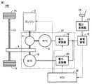
図1は、この発明の実施の形態1に従うハイブリッド車両の全体構成を説明するためのブロック図である。図1を参照して、ハイブリッド車両100は、エンジン2と、駆動装置22と、伝達ギヤ8と、駆動軸12と、車輪14と、蓄電装置16とを備える。また、ハイブリッド車両100は、電力変換器23と、接続部24と、ECU(Electronic Control Unit)26とをさらに備える。
[Embodiment 1]
FIG. 1 is a block diagram for illustrating the overall configuration of a hybrid vehicle according to the first embodiment of the present invention. Referring to FIG. 1,
エンジン2は、燃料の燃焼による熱エネルギーをピストンやロータなどの運動子の運動エネルギーに変換することによって動力を出力する内燃機関である。エンジン2の燃料としては、ガソリンや軽油、エタノール、液体水素、天然ガスなどの炭化水素系燃料、又は、液体もしくは気体の水素燃料が好適である。
The
駆動装置22は、動力分割装置4と、モータジェネレータ6,10と、電力変換器18,20とを含む。モータジェネレータ6,10は、交流回転電機であり、たとえば、3相交流同期電動機によって構成される。モータジェネレータ6は、動力分割装置4を経由してエンジン2により駆動される発電機として用いられるとともに、エンジン2を始動するための電動機としても用いられる。モータジェネレータ10は、主として電動機として動作し、駆動軸12を駆動する。一方で、車両の制動時や下り斜面での加速度低減時には、モータジェネレータ10は、発電機として動作して回生発電を行なう。
動力分割装置4は、たとえば、サンギヤ、キャリア、リングギヤの3つの回転軸を有する遊星歯車機構を含む。動力分割装置4は、エンジン2の駆動力を、モータジェネレータ6の回転軸に伝達される動力と、伝達ギヤ8に伝達される動力とに分割する。伝達ギヤ8は、車輪14を駆動するための駆動軸12に連結される。また、伝達ギヤ8は、モータジェネレータ10の回転軸にも連結される。
The power split device 4 includes, for example, a planetary gear mechanism having three rotation shafts of a sun gear, a carrier, and a ring gear. Power split device 4 divides the driving force of
蓄電装置16は、再充電可能な直流電源であり、たとえば、ニッケル水素電池やリチウムイオン電池等の二次電池によって構成される。蓄電装置16は、電力変換器18,20へ電力を供給する。また、蓄電装置16は、モータジェネレータ6及び/又は10の発電時に発電電力を受けて充電される。なお、蓄電装置16として、大容量のキャパシタも採用可能である。
The
蓄電装置16の充電状態は、蓄電装置16の満充電状態に対する現在の蓄電量を百分率で表したSOC値によって示される。SOC値は、たとえば、図示されない電圧センサ及び/又は電流センサによって検出される、蓄電装置16の出力電圧及び/又は入出力電流に基づいて算出される。SOC値は、蓄電装置16に別途設けられるECUで算出してもよいし、蓄電装置16の出力電圧及び/又は入出力電流の検出値に基づいてECU26で算出してもよい。
The state of charge of
電力変換器18は、ECU26から受ける制御信号に基づいて、モータジェネレータ6と蓄電装置16との間で双方向の直流/交流電力変換を実行する。同様に、電力変換器20は、ECU26から受ける制御信号に基づいて、モータジェネレータ10と蓄電装置16との間で双方向の直流/交流電力変換を実行する。これにより、モータジェネレータ6,10は、蓄電装置16との間での電力の授受を伴なって、電動機として動作するための正トルク又は発電機として動作するための負トルクを出力することができる。なお、蓄電装置16と電力変換器18,20との間に、直流電圧変換のための昇圧コンバータを配置することも可能である。
このように、モータジェネレータ6,10、動力分割装置4、及び電力変換器18,20によって構成される駆動装置22は、車両駆動力を発生するとともに、エンジン2の出力を用いてモータジェネレータ6により蓄電装置16を充電するための電力を生成することができる。
As described above, the
電力変換器23は、ECU26から受ける制御信号に基づいて、接続部24に電気的に接続される車両外部の電源(図示せず)から供給される電力を蓄電装置16の電圧レベルに変換して蓄電装置16へ出力する(以下、車両外部の電源による蓄電装置16の充電を「外部充電」とも称する。)。
Based on a control signal received from
ECU26は、CPU(Central Processing Unit)、記憶装置、入出力バッファ等を含み(いずれも図示せず)、ハイブリッド車両100における各機器の制御を行なう。なお、これらの制御については、ソフトウェアによる処理に限られず、専用のハードウェア(電子回路)で処理することも可能である。
The
ECU26の主要な制御として、ECU26は、アクセルペダルの操作量に応じたアクセル開度に基づいて車両要求パワー(以下、単に「要求パワー」とも称する。)を設定する。そして、ECU26は、要求パワーに相当する車両駆動力を発生するように駆動装置22を制御する。
As main control of the
ECU26は、車両駆動力が小さいときは、エンジン2を停止させてモータジェネレータ10のみで走行(EV走行)するように駆動装置22を制御する。車両駆動力が大きくなったり、SOCが低下したりすると、ECU26は、エンジン2を作動させて走行(HV走行)するように駆動装置22を制御する。HV走行では、モータジェネレータ10の駆動力に加えて、又はモータジェネレータ10の代わりに、エンジン2の駆動力を用いてハイブリッド車両100が走行する。エンジン2の作動に伴ないモータジェネレータ6が発電した電力は、モータジェネレータ10に直接供給されたり、蓄電装置16に蓄えられたりする。
When the vehicle driving force is small, the
また、ECU26は、SOCを消費するCDモードと、SOCを所定レベルに維持するCSモードとを選択的に適用して車両の走行を制御する走行制御を実行する。
Further, the
図2は、CDモード及びCSモードを説明するための図である。図2を参照して、たとえば、外部充電により蓄電装置16が満充電状態となった後、CDモードで走行が開始されるものとする。
FIG. 2 is a diagram for explaining the CD mode and the CS mode. Referring to FIG. 2, for example, it is assumed that traveling is started in the CD mode after
CDモードは、SOCを消費するモードであり、基本的には、蓄電装置16に蓄えられた電力(主には外部充電による電気エネルギー)を消費するものである。CDモードでの走行時は、SOCを維持するためにはエンジン2は作動しない。これにより、車両の減速時等に回収される回生電力やエンジン2の作動に伴ない発電される電力により一時的にSOCが増加することはあるものの、結果的に充電よりも放電の割合の方が相対的に大きくなり、全体としては走行距離の増加に伴ないSOCが減少する。
The CD mode is a mode in which the SOC is consumed, and basically consumes electric power (mainly electric energy by external charging) stored in the
CSモードは、SOCを所定レベルに維持するモードである。一例として、時刻t1において、SOCの低下を示す所定値SLにSOCが低下すると、CSモードが選択され、その後のSOCが、所定値SLに基づき定められる制御範囲RNG内に維持される。具体的には、エンジン2が作動及び停止を適宜繰り返す(間欠運転)ことによって、SOCが制御範囲RNG内に制御される。このように、CSモードでは、SOCを維持するためにエンジン2が作動する。
The CS mode is a mode for maintaining the SOC at a predetermined level. As an example, when the SOC decreases to a predetermined value SL indicating a decrease in SOC at time t1, the CS mode is selected, and the subsequent SOC is maintained within a control range RNG determined based on the predetermined value SL. Specifically, the SOC is controlled within the control range RNG by appropriately repeating the operation and stop of the engine 2 (intermittent operation). As described above, in the CS mode, the
なお、CDモードにおいても、大きな車両駆動力(要求パワー)が要求されればエンジン2は作動する。一方、CSモードにおいても、SOCが上昇すればエンジン2は停止する。すなわち、CDモードは、エンジン2を常時停止させて走行するEV走行に限定されるものではなく、CSモードも、エンジン2を常時作動させて走行するHV走行に限定されるものではない。CDモードにおいても、CSモードにおいても、EV走行とHV走行とが可能である。
Even in the CD mode, the
再び図1を参照して、ECU26は、CDモードが選択されているときは、CSモードが選択されているときよりも、同一のアクセル開度(アクセルペダルの操作量)に対する車両駆動力が小さくなるように車両駆動力を制御する。具体的には、ECU26は、CDモードが選択されているときは、CSモードが選択されているときよりも、同一のアクセル開度に対する要求パワーが小さくなるように要求パワーを設定する。
Referring to FIG. 1 again, when the CD mode is selected, the
CDモードでは、SOCを維持するためにエンジン2は作動しないので、その分、CSモードに比べて燃費はよい。しかしながら、CDモードにおいても、大きな車両駆動力が要求されれば、車両駆動力を確保するためにエンジン2が作動する。エンジン2が作動すれば、燃費は悪化する。そこで、この実施の形態1に従うハイブリッド車両100では、CDモードが選択されているときの要求パワーを上記のように設定することにより、CDモードで走行中の車両駆動力を抑える。これにより、CDモードにおいて、車両駆動力を確保するためにエンジン2を作動させる頻度が抑制される。その結果、CDモードにおける燃費が向上する。
In the CD mode, since the
図3は、アクセル開度と要求パワーとの関係を示した図である。図3を参照して、横軸はアクセル開度を示し、アクセル開度100%はアクセル全開に相当する。縦軸は要求パワーreqを示し、車両駆動力に相当する。この実施の形態1では、CSモードにおいては、アクセル開度と要求パワーとの基本的な関係を示すノーマルラインL1に従って、アクセル開度に応じて要求パワーreqが設定される。 FIG. 3 is a diagram showing the relationship between the accelerator opening and the required power. Referring to FIG. 3, the horizontal axis indicates the accelerator opening, and the accelerator opening 100% corresponds to the accelerator fully open. The vertical axis represents the required power req and corresponds to the vehicle driving force. In the first embodiment, in the CS mode, the required power req is set according to the accelerator opening in accordance with the normal line L1 indicating the basic relationship between the accelerator opening and the required power.
一方、CDモードにおいては、ノーマルラインL1に代えて、出力抑制ラインL2が用いられる。すなわち、CDモードでは、アクセル開度が0%(全閉)から100%(全開)の間において、同一のアクセル開度に対する要求パワーreqがノーマルラインL1よりも小さくなる出力抑制ラインL2に従って、アクセル開度に応じて要求パワーreqが設定される。これにより、CDモードにおいて、要求パワー(車両駆動力)が抑制されることでEV走行からHV走行への切替が抑制され、低燃費の走行が実現される。 On the other hand, in the CD mode, the output suppression line L2 is used instead of the normal line L1. In other words, in the CD mode, when the accelerator opening is between 0% (fully closed) and 100% (fully opened), the accelerator is operated according to the output suppression line L2 in which the required power req for the same accelerator opening is smaller than the normal line L1. The required power req is set according to the opening. Thereby, in the CD mode, the required power (vehicle driving force) is suppressed, so that switching from EV traveling to HV traveling is suppressed, and traveling with low fuel consumption is realized.
図4は、ECU26により実行される要求パワー設定処理の手順を説明するためのフローチャートである。なお、このフローチャートに示される処理は、所定時間毎又は所定条件の成立時にメインルーチンから呼び出されて実行される。
FIG. 4 is a flowchart for explaining the procedure of the required power setting process executed by the
図4を参照して、ECU26は、アクセル開度を検出する(ステップS10)。アクセル開度は、たとえば、アクセルペダルの操作量を検知可能な図示しないセンサによって検出される。次いで、ECU26は、CDモードが選択されているか否かを判定する(ステップS20)。この判定は、たとえば、図2に示したCDモード区間中かCSモード区間中かによって状態が切替わるフラグに基づいて行なわれてもよいし、SOC値そのものに基づいて行なわれてもよい。
Referring to FIG. 4,
ステップS20において、モードはCDモードであると判定されると(ステップS20においてYES)、ECU26は、図3に示した出力抑制ラインL2に従って、ステップS10において検出されたアクセル開度に基づいて要求パワーreqを設定する(ステップS30)。
If it is determined in step S20 that the mode is the CD mode (YES in step S20), the
ステップS20において、モードはCDモードでない、すなわちモードはCSモードであると判定されると(ステップS20においてNO)、ECU26は、図3に示したノーマルラインL1に従って、ステップS10において検出されたアクセル開度に基づいて要求パワーreqを設定する(ステップS40)。
If it is determined in step S20 that the mode is not the CD mode, that is, the mode is the CS mode (NO in step S20),
以上のように、この実施の形態1においては、CDモードが選択されているときは、CSモードが選択されているときよりも、同一のアクセル開度に対する車両駆動力が小さいので、CDモードにおいて、車両駆動力を確保するためにエンジン2を作動させる頻度が抑制される。したがって、この実施の形態1によれば、CDモードにおける燃費を向上させることができる。
As described above, in the first embodiment, when the CD mode is selected, the vehicle driving force for the same accelerator opening is smaller than when the CS mode is selected. The frequency at which the
[実施の形態1の変形例]
上記の実施の形態1では、要求パワーの最大値、すなわちアクセル開度が100%(全開)のときの要求パワー(車両駆動力)は、CDモードでもCSモードと同じであったが、この変形例では、CDモードにおいては、CSモード時よりも要求パワー(車両駆動力)の最大値が小さい。これにより、過度なアクセル操作に対しても、車両駆動力が確実に抑制され、その結果、燃費を確実に向上させることが可能となる。
[Modification of Embodiment 1]
In the first embodiment, the maximum required power, that is, the required power (vehicle driving force) when the accelerator opening is 100% (fully open) is the same as that in the CS mode in the CD mode. In the example, the maximum value of required power (vehicle driving force) is smaller in the CD mode than in the CS mode. As a result, the vehicle driving force is reliably suppressed even when the accelerator operation is excessive, and as a result, the fuel consumption can be reliably improved.
図5は、この変形例におけるアクセル開度と要求パワーとの関係を示した図である。図5を参照して、この図は、上述の図3に対応するものであり、CSモードにおいては、実施の形態1と同様に、ノーマルラインL1に従って、アクセル開度に応じて要求パワーreqが設定される。 FIG. 5 is a diagram showing the relationship between the accelerator opening and the required power in this modification. Referring to FIG. 5, this figure corresponds to FIG. 3 described above, and in the CS mode, the required power req depends on the accelerator opening according to the normal line L1, as in the first embodiment. Is set.
一方、CDモードにおいては、図3に示した出力抑制ラインL2に代えて、出力抑制ラインL3が用いられる。この出力抑制ラインL3については、同一のアクセル開度に対する要求パワーreqがノーマルラインL1よりも小さく、かつ、アクセル開度100%における要求パワーの値(P2)すなわち車両駆動力の最大値がノーマルラインL1の値(P1)よりも小さい。これにより、ユーザが過度なアクセル操作を行なっても、車両駆動力が確実に抑制され、燃費を確実に向上できる。 On the other hand, in the CD mode, an output suppression line L3 is used instead of the output suppression line L2 shown in FIG. For this output suppression line L3, the required power req for the same accelerator opening is smaller than that of the normal line L1, and the required power value (P2) at the accelerator opening 100%, that is, the maximum value of the vehicle driving force is the normal line. It is smaller than the value of L1 (P1). Thereby, even if the user performs an excessive accelerator operation, the vehicle driving force is reliably suppressed, and the fuel consumption can be improved with certainty.
なお、この変形例に従うハイブリッド車両では、さらに、CDモードにおいてアクセル開度が100%であるときの要求パワーP2が、走行用のモータジェネレータ10の効率に基づいて決定される。これにより、モータジェネレータ10の効率を向上させ、その結果として燃費の向上がさらに図られている。以下、この点について説明する。
In the hybrid vehicle according to this modification, the required power P2 when the accelerator opening is 100% in the CD mode is further determined based on the efficiency of the
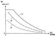
図6は、走行用のモータジェネレータ10の特性曲線を示した図である。図6を参照して、横軸は、モータジェネレータ10の回転数を示し、縦軸は、モータジェネレータ10のトルクを示す。実線で示されるラインL4は、モータジェネレータ10の最大トルクラインを示す。
FIG. 6 is a diagram showing a characteristic curve of the
点線で示されるラインL5は、モータジェネレータ10の各回転数においてモータジェネレータ10の効率が略最大となる最大効率ラインを示す。一点鎖線で示されるラインL6は、モータジェネレータ10の最大効率のたとえば−5%の効率でモータジェネレータ10が作動するラインである。ラインL6よりもトルクが大きくなると、モータジェネレータ10の効率はさらに低下する。
A line L5 indicated by a dotted line indicates a maximum efficiency line at which the efficiency of the
そして、この変形例では、ラインL6に基づいて、図5に示した要求パワーP2の値が決定される。たとえば、ラインL6をモータジェネレータ10の等パワー線で近似し、その等パワー線が示すパワーが要求パワーP2として設定される。これにより、アクセル開度100%(車両駆動力の最大値)に対して、モータジェネレータ10の効率低下は最大効率の−5%に抑えられ、モータジェネレータ10の効率を高い状態に維持することができる。その結果、燃費も向上する。
In this modification, the value of the required power P2 shown in FIG. 5 is determined based on the line L6. For example, the line L6 is approximated by an equal power line of the
以上のように、この変形例においては、CDモードでは、要求パワー(車両駆動力)の最大値が抑制される。これにより、CDモードにおいて、過度なアクセル操作に対する車両駆動力が抑制され、エンジン2の作動が抑制される。したがって、この変形例によれば、燃費を確実に向上させることができる。
As described above, in this modification, the maximum value of the required power (vehicle driving force) is suppressed in the CD mode. Thereby, in CD mode, the vehicle driving force with respect to excessive accelerator operation is suppressed, and the action | operation of the
また、この変形例においては、CDモードにおいて、アクセル開度が100%であるときの要求パワーP2は、上記のように走行用のモータジェネレータ10の効率に基づいて決定される。したがって、この変形例によれば、CDモードにおいてモータジェネレータ10の効率を高い状態に維持することができ、この点でも燃費の向上が図られる。
In this modification, the required power P2 when the accelerator opening is 100% in the CD mode is determined based on the efficiency of the traveling
[実施の形態2]
この実施の形態2では、車両の加速性よりも燃費の低減を優先した走行を可能とするECOモードスイッチが設けられる。そして、ECOモードスイッチがユーザにより操作されてECOモードが選択された場合において、CDモード中は、CSモード中よりも、同一のアクセル開度に対する車両駆動力が小さくなるように要求パワーが設定される。
[Embodiment 2]
In the second embodiment, an ECO mode switch is provided that enables traveling that prioritizes the reduction of fuel consumption over the acceleration of the vehicle. When the ECO mode switch is operated by the user and the ECO mode is selected, the required power is set so that the vehicle driving force for the same accelerator opening is smaller in the CD mode than in the CS mode. The
図7は、実施の形態2に従うハイブリッド車両の全体構成を説明するためのブロック図である。図7を参照して、このハイブリッド車両100Aは、図1に示したハイブリッド車両100の構成において、ECOモードスイッチ28をさらに備え、ECU26に代えてECU26Aを備える。
FIG. 7 is a block diagram for illustrating the overall configuration of the hybrid vehicle according to the second embodiment. Referring to FIG. 7, this
ECOモードスイッチ28は、加速性よりも燃費低減を優先させて走行するECOモードをユーザが選択するための入力スイッチである。ECOモードスイッチ28は、ユーザによるオン操作に応答して信号ECをECU26Aへ出力する。
The
ECU26Aは、ECOモードが選択されているときは、ECOモードが選択されていないノーマルモードのときよりも、同一のアクセル開度(アクセルペダルの操作量)に対する車両駆動力が小さくなるように車両駆動力を制御する。さらに、ECU26Aは、ECOモードが選択されている場合において、CDモードが選択されているときは、CSモードが選択されているときよりも、同一のアクセル開度に対する車両駆動力が小さくなるように車両駆動力を制御する。具体的には、ECU26Aは、ECOモードが選択されている場合において、CDモードが選択されているときは、CSモードが選択されているときよりも、同一のアクセル開度に対する要求パワーが小さくなるように要求パワーを設定する。
The
図8は、実施の形態2におけるアクセル開度と要求パワーとの関係を示した図である。図8を参照して、この実施の形態2では、ノーマルモード(ECOモードの非選択時)では、アクセル開度と要求パワーとの基本的な関係を示すノーマルラインL11に従って、アクセル開度に応じて要求パワーreqが設定される。 FIG. 8 is a diagram showing the relationship between the accelerator opening and the required power in the second embodiment. Referring to FIG. 8, in the second embodiment, in the normal mode (when the ECO mode is not selected), according to the accelerator opening in accordance with normal line L11 indicating the basic relationship between the accelerator opening and the required power. Request power req is set.
ECOモードでは、同一のアクセル開度に対する要求パワーがノーマルモードよりも小さくなるように要求パワーが設定される。具体的には、ECOモードが選択されている場合において、CSモード時は、ノーマルラインL11よりも要求パワーが小さい第1出力抑制ラインL12に従って、アクセル開度に応じて要求パワーreqが設定される。CDモード時は、第1出力抑制ラインL12よりもさらに要求パワーが小さい第2出力抑制ラインL13に従って、アクセル開度に応じて要求パワーreqが設定される。 In the ECO mode, the required power is set so that the required power for the same accelerator opening is smaller than in the normal mode. Specifically, when the ECO mode is selected, in the CS mode, the required power req is set according to the accelerator opening according to the first output suppression line L12 having a required power smaller than that of the normal line L11. . In the CD mode, the required power req is set according to the accelerator opening in accordance with the second output suppression line L13 having a smaller required power than the first output suppression line L12.
ECOモードの選択中にCDモードで走行しているときは、特に低燃費走行が要求されるところ、この実施の形態2では、このような場合に、第2出力抑制ラインL13に従って、アクセル開度に応じて要求パワーreqが設定される。これにより、要求パワー(車両駆動力)が抑制されることでEV走行からHV走行への切替が抑制され、その結果、低燃費の走行が実現される。 When the vehicle is traveling in the CD mode while the ECO mode is selected, particularly low fuel consumption traveling is required. In this second embodiment, in such a case, the accelerator opening degree is determined according to the second output suppression line L13. The required power req is set according to the above. Thus, the required power (vehicle driving force) is suppressed, so that switching from EV traveling to HV traveling is suppressed, and as a result, traveling with low fuel consumption is realized.
図9は、実施の形態2におけるECU26Aにより実行される要求パワー設定処理の手順を説明するためのフローチャートである。なお、このフローチャートに示される処理も、所定時間毎又は所定条件の成立時にメインルーチンから呼び出されて実行される。
FIG. 9 is a flowchart for illustrating a procedure of required power setting processing executed by
図9を参照して、ECU26Aは、アクセル開度を検出する(ステップS110)。次いで、ECU26Aは、ECOモードスイッチ28からの信号ECに基づいて、ECOモードが選択されているか否かを判定する(ステップS120)。ECOモードは選択されていない、すなわちノーマルモードであると判定されると(ステップS120においてNO)、ECU26Aは、図8に示したノーマルラインL11に従って、ステップS110において検出されたアクセル開度に基づいて要求パワーreqを設定する(ステップS160)。
Referring to FIG. 9,
ステップS120において、ECOモードが選択されていると判定されると(ステップS120においてYES)、ECU26Aは、CDモードが選択されているか否かを判定する(ステップS130)。
If it is determined in step S120 that the ECO mode is selected (YES in step S120),
モードはCDモードであると判定されると(ステップS130においてYES)、ECU26Aは、図8に示した第2出力抑制ラインL13に従って、アクセル開度に基づいて要求パワーreqを設定する(ステップS140)。
If it is determined that the mode is the CD mode (YES in step S130),
一方、ステップS130において、モードはCDモードでない、すなわちモードはCSモードであると判定されると(ステップS130においてNO)、ECU26Aは、図8に示した第1出力抑制ラインL12に従って、アクセル開度に基づいて要求パワーreqを設定する(ステップS150)。
On the other hand, when it is determined in step S130 that the mode is not the CD mode, that is, the mode is the CS mode (NO in step S130),
以上のように、ECOモードの選択中にCDモードで走行しているときは、特に低燃費走行が要求されるところ、この実施の形態2においては、このような場合に、第2出力抑制ラインL13に従って、アクセル開度に応じて要求パワーreqが設定される。したがって、この実施の形態2によれば、要求パワー(車両駆動力)が抑制されることでEV走行からHV走行への切替が抑制され、その結果、燃費を向上させることができる。 As described above, when the vehicle is traveling in the CD mode while the ECO mode is selected, particularly low fuel consumption traveling is required. In the second embodiment, the second output suppression line is used in such a case. In accordance with L13, the required power req is set according to the accelerator opening. Therefore, according to the second embodiment, since the required power (vehicle driving force) is suppressed, switching from EV traveling to HV traveling is suppressed, and as a result, fuel consumption can be improved.
[実施の形態2の変形例]
実施の形態1の変形例と同様に、この変形例では、ECOモードの選択中にCDモードで走行しているときは、ノーマルモードのとき(ECOモードの非選択時)、又はECOモードの選択中にCSモードで走行しているときよりも、要求パワー(車両駆動力)の最大値が小さい。これにより、過度なアクセル操作に対しても、車両駆動力が確実に抑制され、その結果、CDモードにおける燃費を確実に向上させることが可能となる。
[Modification of Embodiment 2]
Similar to the modified example of the first embodiment, in this modified example, when the vehicle is traveling in the CD mode while the ECO mode is selected, the normal mode is selected (when the ECO mode is not selected), or the ECO mode is selected. The maximum value of required power (vehicle driving force) is smaller than when traveling in the CS mode. As a result, the vehicle driving force is reliably suppressed even when the accelerator operation is excessive, and as a result, the fuel efficiency in the CD mode can be reliably improved.
図10は、実施の形態2の変形例におけるアクセル開度と要求パワーとの関係を示した図である。図10を参照して、この図は、上述の図8に対応するものであり、ノーマルモードにおいては、実施の形態2と同様に、ノーマルラインL11に従って、アクセル開度に応じて要求パワーreqが設定される。また、ECOモードが選択されている場合において、CSモードのときも、実施の形態2と同様に、第1出力抑制ラインL12に従って、アクセル開度に応じて要求パワーreqが設定される。 FIG. 10 is a diagram showing the relationship between the accelerator opening and the required power in a modification of the second embodiment. Referring to FIG. 10, this figure corresponds to FIG. 8 described above. In the normal mode, the required power req depends on the accelerator opening according to the normal line L11, as in the second embodiment. Is set. Further, when the ECO mode is selected, the required power req is set according to the accelerator opening according to the first output suppression line L12 as in the second embodiment even in the CS mode.
一方、ECOモードが選択されている場合において、CDモードのときは、図8に示した第2出力抑制ラインL13に代えて、第3出力抑制ラインL14が用いられる。この第3出力抑制ラインL14については、同一のアクセル開度に対する要求パワーreqが第1出力抑制ラインL12よりも小さく、かつ、アクセル開度100%における要求パワーの値(P2)すなわち車両駆動力の最大値が第1出力抑制ラインL12の値(P1)よりも小さい。これにより、ユーザが過度なアクセル操作を行なっても、車両駆動力が確実に抑制され、燃費を確実に向上できる。 On the other hand, when the ECO mode is selected and in the CD mode, the third output suppression line L14 is used instead of the second output suppression line L13 shown in FIG. Regarding the third output suppression line L14, the required power req for the same accelerator opening is smaller than that of the first output suppression line L12, and the required power value (P2) at the accelerator opening 100%, that is, the vehicle driving force. The maximum value is smaller than the value (P1) of the first output suppression line L12. Thereby, even if the user performs an excessive accelerator operation, the vehicle driving force is reliably suppressed, and the fuel consumption can be improved with certainty.
なお、この変形例においても、ECOモードが選択されている場合のCDモードにおいて、アクセル開度が100%であるときの要求パワーP2は、上述の図5,6で説明したように、たとえば、走行用のモータジェネレータ10の効率に基づいて決定される。
Also in this modification, the required power P2 when the accelerator opening is 100% in the CD mode when the ECO mode is selected is, for example, as described in FIGS. It is determined based on the efficiency of the
以上のように、この実施の形態2の変形例によれば、ECOモードが選択されている場合に、CDモードにおいて、過度なアクセル操作に対する車両駆動力が抑制され、エンジン2の作動が抑制される。したがって、この変形例によれば、燃費を確実に向上させることができる。また、モータジェネレータ10の効率を高い状態に維持することができ、この点でも燃費の向上が図られる。
As described above, according to the modification of the second embodiment, when the ECO mode is selected, the vehicle driving force against excessive accelerator operation is suppressed and the operation of the
なお、上記の各実施の形態では、エンジン2と2つのモータジェネレータ6,10とが動力分割装置4によって連結された構成のハイブリッド車両100,100A(図1,7)について説明したが、この発明が適用されるハイブリッド車両は、このような構成のものに限定されない。
In each of the above embodiments, the
たとえば、エンジン2と1つのモータジェネレータ10とが、クラッチを介して直列的に連結された構成のハイブリッド車両等に対しても、上記の各実施の形態で説明した制御を適用することが可能である。また、モータジェネレータ6を駆動するためにのみエンジン2を用い、モータジェネレータ10でのみ車両の駆動力を発生する、いわゆるシリーズ型のハイブリッド車両にも、この発明は適用可能である。
For example, the control described in each of the above embodiments can be applied to a hybrid vehicle or the like in which the
また、上記の各実施の形態では、ハイブリッド車両100,100Aは、外部充電可能な所謂プラグインハイブリッド車として説明したが、この発明が適用されるハイブリッド車両は、プラグインハイブリッド車に限定されない。すなわち、車両外部の電源によって蓄電装置16を充電する充電機構(電力変換器23及び接続部24)を備えないハイブリッド車両にも、この発明は適用可能である。
In each of the above embodiments,
なお、上記において、モータジェネレータ6,10、動力分割装置4、及び電力変換器18,20は、この発明における「駆動装置」の一実施例に対応する。また、エンジン2は、この発明における「内燃機関」の一実施例に対応し、ECU26は、この発明における「制御装置」の一実施例に対応する。さらに、モータジェネレータ10は、この発明における「電動機」の一実施例に対応し、電力変換器23及び接続部24は、この発明における「充電機構」の一実施例を形成する。
In the above,
今回開示された各実施の形態は、適宜組合わせて実施することも予定されている。そして、今回開示された実施の形態は、すべての点で例示であって制限的なものではないと考えられるべきである。本発明の範囲は、上記した実施の形態の説明ではなくて特許請求の範囲によって示され、特許請求の範囲と均等の意味及び範囲内でのすべての変更が含まれることが意図される。 The embodiments disclosed this time are also scheduled to be implemented in appropriate combinations. The embodiment disclosed this time should be considered as illustrative in all points and not restrictive. The scope of the present invention is shown not by the above description of the embodiment but by the scope of claims, and is intended to include all modifications within the meaning and scope equivalent to the scope of claims.
2 エンジン、4 動力分割装置、6,10 モータジェネレータ、8 伝達ギヤ、12 駆動軸、14 車輪、16 蓄電装置、18,20,23 電力変換器、22 駆動装置、24 接続部、26,26A ECU、28 ECOモードスイッチ、100,100A ハイブリッド車両。 2 Engine, 4 Power split device, 6, 10 Motor generator, 8 Transmission gear, 12 Drive shaft, 14 Wheel, 16 Power storage device, 18, 20, 23 Power converter, 22 Drive device, 24 Connection, 26, 26A ECU , 28 ECO mode switch, 100, 100A hybrid vehicle.
Claims (6)
前記蓄電装置に蓄えられた電力を受けて車両駆動力を発生する駆動装置と、
内燃機関とを備え、
前記駆動装置は、さらに、前記内燃機関の出力を用いて前記蓄電装置を充電するための電力を生成可能に構成され、さらに
前記蓄電装置のSOCを消費するCD(Charge Depleting)モードと、前記SOCを所定レベルに維持するCS(Charge Sustaining)モードとのいずれかを選択して走行するための制御装置を備え、
前記駆動装置は、車両駆動力を発生する電動機を含み、
前記制御装置は、前記CDモードにおいて、走行状況に応じて、前記内燃機関を停止して前記電動機により走行するEV走行と、前記内燃機関を作動させて走行するHV走行とを切り替え、
前記制御装置は、前記EV走行中か前記HV走行中かに拘わらず、前記CDモードが選択されているときは、前記CSモードが選択されているときよりも、同一のアクセル開度に対する車両駆動力が小さくなるように車両駆動力を制御する、ハイブリッド車両。 A power storage device;
A driving device that receives electric power stored in the power storage device and generates vehicle driving force;
An internal combustion engine,
The drive device is further configured to be able to generate electric power for charging the power storage device using the output of the internal combustion engine, and further, a CD (Charge Depleting) mode for consuming the SOC of the power storage device, and the SOC A control device for driving by selecting one of CS (Charge Sustaining) mode for maintaining the vehicle at a predetermined level,
The driving device includes an electric motor that generates a vehicle driving force,
In the CD mode, the control device switches between EV traveling in which the internal combustion engine is stopped and traveling by the electric motor and HV traveling in which the internal combustion engine is operated in accordance with a traveling state,
When the CD mode is selected, the control device drives the vehicle to the same accelerator opening degree when the CD mode is selected , regardless of whether the EV traveling or the HV traveling is performed. A hybrid vehicle that controls the vehicle driving force so that the force is reduced.
前記蓄電装置に蓄えられた電力を受けて車両駆動力を発生する駆動装置と、A driving device that receives electric power stored in the power storage device and generates vehicle driving force;
内燃機関とを備え、An internal combustion engine,
前記駆動装置は、さらに、前記内燃機関の出力を用いて前記蓄電装置を充電するための電力を生成可能に構成され、さらにThe drive device is further configured to generate electric power for charging the power storage device using an output of the internal combustion engine, and
前記蓄電装置のSOCを消費するCD(Charge Depleting)モードと、前記SOCを所定レベルに維持するCS(Charge Sustaining)モードとのいずれかを選択して走行するための制御装置を備え、A control device for traveling by selecting one of a CD (Charge Depleting) mode for consuming the SOC of the power storage device and a CS (Charge Sustaining) mode for maintaining the SOC at a predetermined level;
前記駆動装置は、車両駆動力を発生する電動機を含み、The driving device includes an electric motor that generates a vehicle driving force,
前記制御装置は、前記CDモードにおいて、走行状況に応じて、前記内燃機関を停止して前記電動機により走行するEV走行と、前記内燃機関を作動させて走行するHV走行とを切り替え、In the CD mode, the control device switches between EV traveling in which the internal combustion engine is stopped and traveling by the electric motor and HV traveling in which the internal combustion engine is operated in accordance with a traveling state,
前記制御装置は、前記CDモードが選択されているときは、前記CSモードが選択されているときよりも、同一のアクセル開度に対するHV走行中の車両駆動力が小さくなるように車両駆動力を制御する、ハイブリッド車両。When the CD mode is selected, the control device reduces the vehicle driving force so that the vehicle driving force during HV traveling for the same accelerator opening is smaller than when the CS mode is selected. Hybrid vehicle to be controlled.
前記蓄電装置に蓄えられた電力を受けて車両駆動力を発生する駆動装置と、
内燃機関とを備え、
前記駆動装置は、さらに、前記内燃機関の出力を用いて前記蓄電装置を充電するための電力を生成可能に構成され、さらに
前記蓄電装置のSOCを消費するCD(Charge Depleting)モードと、前記SOCを所定レベルに維持するCS(Charge Sustaining)モードとのいずれかを選択して走行するための制御装置を備え、
前記制御装置は、前記CDモードが選択されているときは、前記CSモードが選択されているときよりも、同一のアクセル開度に対する車両駆動力が小さくなるように車両駆動力を制御し、
前記制御装置は、前記CDモードが選択されているときは、前記CSモードが選択されているときよりも、車両駆動力の最大値が小さくなるように車両駆動力を制御する、ハイブリッド車両。 A power storage device;
A driving device that receives electric power stored in the power storage device and generates vehicle driving force;
An internal combustion engine,
The drive device is further configured to generate electric power for charging the power storage device using an output of the internal combustion engine, and
A control device for traveling by selecting one of a CD (Charge Depleting) mode for consuming the SOC of the power storage device and a CS (Charge Sustaining) mode for maintaining the SOC at a predetermined level;
The control device controls the vehicle driving force so that the vehicle driving force with respect to the same accelerator opening is smaller when the CD mode is selected than when the CS mode is selected,
Wherein the controller, when the CD mode is selected than when the CS mode is selected, to control the vehicle driving force so that the maximum value of the vehicle driving force becomes smaller, hybrid vehicle.
前記CDモードが選択されているときの車両駆動力の最大値は、前記電動機のトルクが所定の制限トルクを超えないように設定され、
前記所定の制限トルクは、前記電動機の効率に基づき設定され、前記電動機が出力可能な最大トルクよりも小さい、請求項4に記載のハイブリッド車両。 The driving device includes an electric motor that generates a vehicle driving force,
The maximum value of the vehicle driving force when the CD mode is selected is set so that the torque of the electric motor does not exceed a predetermined limit torque,
The hybrid vehicle according to claim 4 , wherein the predetermined limit torque is set based on an efficiency of the electric motor and is smaller than a maximum torque that can be output by the electric motor.
Priority Applications (4)
| Application Number | Priority Date | Filing Date | Title |
|---|---|---|---|
| JP2014138790A JP6149814B2 (en) | 2014-07-04 | 2014-07-04 | Hybrid vehicle |
| US14/753,260 US9878701B2 (en) | 2014-07-04 | 2015-06-29 | Hybrid vehicle |
| DE102015110688.4A DE102015110688B9 (en) | 2014-07-04 | 2015-07-02 | HYBRID VEHICLE |
| CN201510388623.5A CN105235678B (en) | 2014-07-04 | 2015-07-03 | Motor vehicle driven by mixed power |
Applications Claiming Priority (1)
| Application Number | Priority Date | Filing Date | Title |
|---|---|---|---|
| JP2014138790A JP6149814B2 (en) | 2014-07-04 | 2014-07-04 | Hybrid vehicle |
Publications (2)
| Publication Number | Publication Date |
|---|---|
| JP2016016689A JP2016016689A (en) | 2016-02-01 |
| JP6149814B2 true JP6149814B2 (en) | 2017-06-21 |
Family
ID=54866360
Family Applications (1)
| Application Number | Title | Priority Date | Filing Date |
|---|---|---|---|
| JP2014138790A Active JP6149814B2 (en) | 2014-07-04 | 2014-07-04 | Hybrid vehicle |
Country Status (4)
| Country | Link |
|---|---|
| US (1) | US9878701B2 (en) |
| JP (1) | JP6149814B2 (en) |
| CN (1) | CN105235678B (en) |
| DE (1) | DE102015110688B9 (en) |
Families Citing this family (3)
| Publication number | Priority date | Publication date | Assignee | Title |
|---|---|---|---|---|
| JP6363493B2 (en) * | 2014-12-19 | 2018-07-25 | トヨタ自動車株式会社 | Hybrid vehicle |
| JP6439722B2 (en) * | 2016-03-08 | 2018-12-19 | トヨタ自動車株式会社 | Hybrid car |
| CN114633757A (en) * | 2020-11-30 | 2022-06-17 | 荷兰移动驱动器公司 | Driving assistance method and vehicle-mounted device |
Family Cites Families (18)
| Publication number | Priority date | Publication date | Assignee | Title |
|---|---|---|---|---|
| JP4254786B2 (en) * | 2006-02-08 | 2009-04-15 | トヨタ自動車株式会社 | Vehicle and control method thereof |
| JP5162998B2 (en) * | 2006-10-12 | 2013-03-13 | 日産自動車株式会社 | Hybrid vehicle mode switching control device |
| JP4232824B2 (en) * | 2006-12-28 | 2009-03-04 | トヨタ自動車株式会社 | Hybrid vehicle and control method thereof |
| JP4997986B2 (en) | 2007-01-19 | 2012-08-15 | トヨタ自動車株式会社 | Control device for hybrid vehicle |
| JP2008296619A (en) * | 2007-05-29 | 2008-12-11 | Toyota Motor Corp | Hybrid vehicle, control method thereof, and computer readable recording medium with program for making computer execute the method recorded thereon |
| JP4341704B2 (en) * | 2007-07-12 | 2009-10-07 | トヨタ自動車株式会社 | Hybrid vehicle and control method of hybrid vehicle |
| JP4818337B2 (en) | 2008-09-17 | 2011-11-16 | 本田技研工業株式会社 | Vehicle control device |
| US8620503B2 (en) * | 2008-12-22 | 2013-12-31 | Toyota Jidosha Kabushiki Kaisha | Hybrid vehicle |
| JP2009143563A (en) * | 2009-01-26 | 2009-07-02 | Toyota Motor Corp | Hybrid vehicle |
| JP2011093335A (en) * | 2009-10-27 | 2011-05-12 | Toyota Motor Corp | Controller for hybrid vehicle |
| JP5316703B2 (en) * | 2010-04-07 | 2013-10-16 | トヨタ自動車株式会社 | Control device for hybrid vehicle and hybrid vehicle including the same |
| JP5187362B2 (en) * | 2010-08-20 | 2013-04-24 | トヨタ自動車株式会社 | Vehicle control device |
| CN103338995B (en) | 2011-02-01 | 2015-05-27 | 丰田自动车株式会社 | Vehicle, control method for vehicle, and control device for vehicle |
| JP2012219795A (en) * | 2011-04-14 | 2012-11-12 | Toyota Motor Corp | Vehicle and control method of the same |
| JP5930018B2 (en) | 2012-02-17 | 2016-06-08 | トヨタ自動車株式会社 | Vehicle and vehicle control method |
| CN102849062B (en) * | 2012-09-18 | 2015-10-14 | 中国第一汽车股份有限公司 | A kind of drived control method of stroke-increasing electric automobile |
| JP6281056B2 (en) | 2012-12-21 | 2018-02-21 | 株式会社高尾 | Circulating game machine |
| CN103192737B (en) * | 2013-03-25 | 2015-10-07 | 吉林大学 | Drive control method for all-electric car |
-
2014
- 2014-07-04 JP JP2014138790A patent/JP6149814B2/en active Active
-
2015
- 2015-06-29 US US14/753,260 patent/US9878701B2/en active Active
- 2015-07-02 DE DE102015110688.4A patent/DE102015110688B9/en active Active
- 2015-07-03 CN CN201510388623.5A patent/CN105235678B/en active Active
Also Published As
| Publication number | Publication date |
|---|---|
| US20160001767A1 (en) | 2016-01-07 |
| CN105235678A (en) | 2016-01-13 |
| DE102015110688A1 (en) | 2016-01-07 |
| DE102015110688B4 (en) | 2023-05-17 |
| US9878701B2 (en) | 2018-01-30 |
| JP2016016689A (en) | 2016-02-01 |
| CN105235678B (en) | 2018-04-03 |
| DE102015110688B9 (en) | 2023-10-19 |
Similar Documents
| Publication | Publication Date | Title |
|---|---|---|
| JP6363493B2 (en) | Hybrid vehicle | |
| JP6213497B2 (en) | Hybrid vehicle | |
| JP6156303B2 (en) | Hybrid vehicle | |
| JP6179504B2 (en) | Hybrid vehicle | |
| JPWO2011128986A1 (en) | Hybrid vehicle | |
| JP5696791B2 (en) | Vehicle and vehicle control method | |
| WO2013018221A1 (en) | Vehicle, and vehicle control method | |
| US9199542B2 (en) | Vehicle and method of controlling vehicle | |
| JP5811181B2 (en) | Vehicle and vehicle control method | |
| JPWO2013065166A1 (en) | Vehicle and vehicle control method | |
| JP6149814B2 (en) | Hybrid vehicle | |
| JP2016117374A (en) | Hybrid vehicle | |
| JPWO2012105021A1 (en) | Hybrid vehicle and control method thereof | |
| US9573581B2 (en) | Hybrid vehicle | |
| US9663100B2 (en) | Hybrid vehicle | |
| JP2013006430A (en) | Hybrid vehicle and control method therefor | |
| JP2015013517A (en) | Vehicle controller | |
| JP2016155486A (en) | Hybrid vehicle | |
| JP2017154582A (en) | Hybrid vehicle | |
| JP2016010981A (en) | Hybrid-vehicular control apparatus |
Legal Events
| Date | Code | Title | Description |
|---|---|---|---|
| A621 | Written request for application examination |
Free format text: JAPANESE INTERMEDIATE CODE: A621 Effective date: 20160120 |
|
| A131 | Notification of reasons for refusal |
Free format text: JAPANESE INTERMEDIATE CODE: A131 Effective date: 20160920 |
|
| A977 | Report on retrieval |
Free format text: JAPANESE INTERMEDIATE CODE: A971007 Effective date: 20160923 |
|
| A521 | Request for written amendment filed |
Free format text: JAPANESE INTERMEDIATE CODE: A523 Effective date: 20161116 |
|
| TRDD | Decision of grant or rejection written | ||
| A01 | Written decision to grant a patent or to grant a registration (utility model) |
Free format text: JAPANESE INTERMEDIATE CODE: A01 Effective date: 20170425 |
|
| A61 | First payment of annual fees (during grant procedure) |
Free format text: JAPANESE INTERMEDIATE CODE: A61 Effective date: 20170508 |
|
| R151 | Written notification of patent or utility model registration |
Ref document number: 6149814 Country of ref document: JP Free format text: JAPANESE INTERMEDIATE CODE: R151 |