JP6142493B2 - Display device, image forming apparatus, and display control program - Google Patents
Display device, image forming apparatus, and display control program Download PDFInfo
- Publication number
- JP6142493B2 JP6142493B2 JP2012221154A JP2012221154A JP6142493B2 JP 6142493 B2 JP6142493 B2 JP 6142493B2 JP 2012221154 A JP2012221154 A JP 2012221154A JP 2012221154 A JP2012221154 A JP 2012221154A JP 6142493 B2 JP6142493 B2 JP 6142493B2
- Authority
- JP
- Japan
- Prior art keywords
- display
- touch panel
- display screen
- scroll
- deformation
- Prior art date
- Legal status (The legal status is an assumption and is not a legal conclusion. Google has not performed a legal analysis and makes no representation as to the accuracy of the status listed.)
- Expired - Fee Related
Links
- 238000012545 processing Methods 0.000 claims description 56
- 230000008859 change Effects 0.000 claims description 27
- 230000004044 response Effects 0.000 claims description 9
- 238000001514 detection method Methods 0.000 claims description 6
- 238000000034 method Methods 0.000 description 34
- 230000008569 process Effects 0.000 description 31
- 238000010586 diagram Methods 0.000 description 15
- 230000010365 information processing Effects 0.000 description 13
- 230000006870 function Effects 0.000 description 10
- 230000004048 modification Effects 0.000 description 9
- 238000012986 modification Methods 0.000 description 9
- 230000009466 transformation Effects 0.000 description 6
- 230000007704 transition Effects 0.000 description 5
- 230000007423 decrease Effects 0.000 description 3
- 238000004891 communication Methods 0.000 description 2
- 230000003247 decreasing effect Effects 0.000 description 2
- 230000002093 peripheral effect Effects 0.000 description 2
- 238000013459 approach Methods 0.000 description 1
- 238000003491 array Methods 0.000 description 1
- 230000015572 biosynthetic process Effects 0.000 description 1
- 239000002131 composite material Substances 0.000 description 1
- 230000007547 defect Effects 0.000 description 1
- 230000000694 effects Effects 0.000 description 1
- 238000005516 engineering process Methods 0.000 description 1
- 230000001747 exhibiting effect Effects 0.000 description 1
- 238000002715 modification method Methods 0.000 description 1
- 238000004091 panning Methods 0.000 description 1
- 230000003068 static effect Effects 0.000 description 1
Images


Landscapes
- Facsimiles In General (AREA)
- User Interface Of Digital Computer (AREA)
Description
この発明は表示装置、画像形成装置、および表示制御プログラムに関し、特に、タッチパネルを有する表示装置、該表示装置を搭載した画像形成装置、および表示制御プログラムに関する。 The present invention relates to a display device, an image forming apparatus, and a display control program, and more particularly to a display device having a touch panel, an image forming apparatus equipped with the display device, and a display control program.
携帯電話機などの携帯端末やMFP(Multi-Functional Peripheral)などの画像形成装置を、搭載されたタッチパネルに対して指を払ったり滑らせたりする、フリックやパンなどと呼ばれるジェスチャーにて操作することが可能になってきている。このような操作は直感的で、操作性を向上させることができる。 It is possible to operate a mobile terminal such as a mobile phone or an image forming apparatus such as an MFP (Multi-Functional Peripheral) with a gesture called flick or pan, which moves or slides a finger on the mounted touch panel. It is becoming possible. Such an operation is intuitive and operability can be improved.
しかしながら、フリックやパンなどのジェスチャー操作で表示画面をスクロールすると、タッチパネルの表示が表示画面の先端や終端に到達しても表示画面の端であることが表示に表れないため、ユーザーは端に到達したことに気付きにくい、という問題がある。表示画面の端であることが表示上で表れないと、ユーザーは、表示画面の端までタッチパネルに表示された後に何度かスクロール操作を行なったにも関わらず表示画面がスクロールされないことを見て、はじめて表示が表示画面の端に到達していることに気付くことになる。このとき、ユーザーは、操作ミスの可能性も考慮して、複数回スクロール操作することもある。そのため、操作効率を落とすことになる。 However, if the display screen is scrolled by gesture operations such as flicking and panning, the end of the display screen does not appear even if the touch panel display reaches the top or end of the display screen, so the user reaches the end. There is a problem that it is difficult to notice that. If the edge of the display screen does not appear on the display, the user sees that the display screen does not scroll even though the user scrolls several times after being displayed on the touch panel to the edge of the display screen. For the first time, you will notice that the display has reached the edge of the display screen. At this time, the user may perform a scroll operation a plurality of times in consideration of the possibility of an operation error. Therefore, the operation efficiency is lowered.
これに対して、たとえば、表示画面にスクロールバーを併設して表示させるようにすることもなされているが、ジェスチャー操作時にはユーザーの視線は操作対象の表示画面上にあってスクロールバーを確認していないことが多いため、依然として表示が表示画面の端に到達したことに気付きにくい、という問題は解消しきれない。 On the other hand, for example, a scroll bar is also displayed on the display screen. However, when performing a gesture operation, the user's line of sight is on the target display screen and the scroll bar is confirmed. In many cases, the problem that it is difficult to notice that the display has reached the edge of the display screen cannot be solved.
また、たとえば特開2011−14078号公報(特許文献1)は、表示が表示画面の端に到達すると、いったん、端より外側の余白領域まで表示した後に、表示画面を表示の端に戻すという表示を行なう技術を開示している。 In addition, for example, in Japanese Patent Application Laid-Open No. 2011-14078 (Patent Document 1), when the display reaches the end of the display screen, the display is once displayed up to the margin area outside the end and then returned to the display end. The technique which performs is disclosed.
しかしながら、この技術を利用すると、表示画面の端の外側の余白領域が表示されるため、表示画面が続いていると誤解される可能性があったり、機器の表示の不具合と誤解される可能性があったりする、という問題がある。 However, if this technology is used, the margin area outside the edge of the display screen is displayed, so it may be misunderstood that the display screen continues, or it may be misunderstood as a display failure of the device. There is a problem that there is.
本発明はこのような問題に鑑みてなされたものであって、タッチパネルでの表示が表示画面の端まで達したことを容易に気付かせることのできる表示装置、画像形成装置、および表示制御プログラムを提供することを目的としている。 The present invention has been made in view of such problems, and provides a display device, an image forming apparatus, and a display control program capable of easily recognizing that the display on the touch panel has reached the end of the display screen. It is intended to provide.
上記目的を達成するために、本発明のある局面に従うと、表示装置はタッチパネルを有する表示装置はであって、電子情報に基づいて生成される表示画面を記憶するための記憶手段と、タッチパネルに対して、タッチパネルの表示に対するスクロール操作がなされたことを検出するための検出手段と、表示画面のうちのタッチパネルに表示されている表示範囲が、スクロール操作で指示されるスクロール方向に移動させても表示画面の端部に到達しない場合に、表示範囲をスクロール方向に移動させてタッチパネルに表示させるためのスクロール処理手段と、スクロール方向に移動させることで表示範囲が表示画面の端部に到達する場合に、表示画面の端部を、タッチパネルの表示領域におけるスクロール方向の端部とし、表示画面に表示される少なくとも一部の画像オブジェクトをスクロール方向に変形させてタッチパネルに表示させるための変形処理手段とを備える。変形処理手段は、表示画面の端部において画像オブジェクトが拡大して変形されるのに応じて、タッチパネルに表示されるスクロールバーのノブを拡大して変形させる。
本発明のさらに他の局面に従うと、表示装置はタッチパネルを有する表示装置はであって、電子情報に基づいて生成される表示画面を記憶するための記憶手段と、前記タッチパネルに対して、前記タッチパネルの表示に対するスクロール操作がなされたことを検出するための検出手段と、前記表示画面のうちの前記タッチパネルに表示されている表示範囲が、前記スクロール操作で指示されるスクロール方向に移動させても前記表示画面の端部に到達しない場合に、前記表示範囲を前記スクロール方向に移動させて前記タッチパネルに表示させるためのスクロール処理手段と、前記スクロール方向に移動させることで前記表示範囲が前記表示画面の端部に到達する場合に、前記表示画面の端部を、前記タッチパネルの表示領域における前記スクロール方向の端部とし、前記表示画面に表示される複数の画像オブジェクトの間隔が変化するように前記表示画面を前記スクロール方向に変形させて前記タッチパネルに表示させるための変形処理手段とを備える。前記変形処理手段は、前記表示画面の端部において前記間隔が拡大して変形されるのに応じて、前記タッチパネルに表示されるスクロールバーのノブを拡大して変形させる。
To achieve the above object, according to an aspect of the present invention, the Viewing apparatus comprising a display device having a touch panel, a storage unit for storing a display screen generated based on the electronic information, a touch panel In contrast, the detection means for detecting that the scroll operation for the display on the touch panel has been performed, and the display range displayed on the touch panel of the display screen are moved in the scroll direction indicated by the scroll operation. If the display screen does not reach the end of the display screen, the display range reaches the end of the display screen by moving the display range in the scroll direction to display on the touch panel and the scroll processing means. In this case, the edge of the display screen is the edge in the scroll direction in the display area of the touch panel and displayed on the display screen. And a transformation processing means for displaying on the touch panel by deforming in the scroll direction at least a portion of the image object that. The deformation processing means expands and deforms the knob of the scroll bar displayed on the touch panel in response to the image object being enlarged and deformed at the end of the display screen.
According to still another aspect of the present invention, the display device is a display device having a touch panel, the storage device for storing a display screen generated based on electronic information, and the touch panel with respect to the touch panel. Detection means for detecting that a scroll operation has been performed on the display, and the display range displayed on the touch panel of the display screen is moved in the scroll direction indicated by the scroll operation. Scroll processing means for moving the display range in the scroll direction to display on the touch panel when the end of the display screen is not reached, and moving the display range in the scroll direction so that the display range is When reaching the edge, the edge of the display screen is moved toward the display area of the touch panel. The roll direction of the end portion, and a deformation processing means for displaying on the touch panel of the display screen is deformed in the scrolling direction so that the distance of a plurality of image objects to be displayed on the display screen is changed. The deformation processing means expands and deforms a knob of a scroll bar displayed on the touch panel in response to the space being enlarged and deformed at the end of the display screen.
好ましくは、表示装置は、スクロール操作の速度から変形量を算出するための算出手段をさらに備える。 Preferably, the display device further includes calculation means for calculating the deformation amount from the speed of the scroll operation.
好ましくは、変形処理手段は、表示画面の端部からスクロール方向に、変形量を変化させて表示範囲の画像を変化させる。 Preferably, the deformation processing means changes the image in the display range by changing the deformation amount in the scroll direction from the end of the display screen.
好ましくは、変形処理手段は、タッチパネルの表示の、スクロール方向に、スクロール操作を受け付けた位置より表示画面の端部に近い側を変形させる。 Preferably, the deformation processing means deforms the side closer to the end of the display screen than the position where the scroll operation is received in the scroll direction of the display on the touch panel.
好ましくは、表示画面が平行に配列されたオブジェクトの列を含み、スクロール方向が列に直交する方向である場合に、変形処理手段は、列の間隔をスクロール方向に変形させる。 Good Mashiku includes a row of objects that display screen are arranged in parallel, when the scroll direction is the direction orthogonal to the column, transformation processing means deforms the spacing of the columns in the scrolling direction.
本発明の他の局面に従うと、画像形成装置は上記表示装置を備える。
本発明のさらに他の局面に従うと、表示制御プログラムはタッチパネルでの電子情報に基づいて生成される表示画面の表示を制御する処理をコンピュータに実行させるプログラムであって、タッチパネルに対して、タッチパネルの表示に対するスクロール操作がなされたことを検出するステップと、表示画面のうちのタッチパネルに表示されている表示範囲が、スクロール操作で指示されるスクロール方向に移動させると、表示画面の端部に到達するか否かを判断するステップと、スクロール方向に移動させても表示範囲が表示画面の端部に到達しない場合に、表示範囲をスクロール方向に移動させてタッチパネルに表示させるステップと、スクロール方向に移動させることで表示範囲が表示画面の端部に到達する場合に、表示画面の端部を、タッチパネルの表示領域におけるスクロール方向の端部とし、表示画面に表示される少なくとも一部の画像オブジェクトをスクロール方向に変形させてタッチパネルに表示させるステップとをコンピュータに実行させる。変形させてタッチパネルに表示させるステップは、表示画面の端部において画像オブジェクトが拡大して変形されるのに応じて、タッチパネルに表示されるスクロールバーのノブを拡大して変形させる。
本発明のさらに他の局面に従うと、表示制御プログラムはタッチパネルでの電子情報に基づいて生成される表示画面の表示を制御する処理をコンピュータに実行させるプログラムであって、タッチパネルに対して、タッチパネルの表示に対するスクロール操作がなされたことを検出するステップと、表示画面のうちのタッチパネルに表示されている表示範囲が、スクロール操作で指示されるスクロール方向に移動させると、表示画面の端部に到達するか否かを判断するステップと、スクロール方向に移動させても表示範囲が表示画面の端部に到達しない場合に、表示範囲をスクロール方向に移動させてタッチパネルに表示させるステップと、スクロール方向に移動させることで表示範囲が表示画面の端部に到達する場合に、表示画面の端部を、タッチパネルの表示領域におけるスクロール方向の端部とし、表示画面に表示される複数の画像オブジェクトの間隔が変化するように表示画面をスクロール方向に変形させてタッチパネルに表示させるステップとをコンピュータに実行させる。変形させてタッチパネルに表示させるステップは、表示画面の端部において間隔が拡大して変形されるのに応じて、タッチパネルに表示されるスクロールバーのノブを拡大して変形させる。
好ましくは、表示制御プログラムは、コンピュータに、スクロール操作の速度から変形量を算出するステップをさらに実行させる。
好ましくは、変形させてタッチパネルに表示させるステップは、表示画面の端部からスクロール方向に、変形量を変化させて表示範囲の画像を変化させる。
好ましくは、変形させてタッチパネルに表示させるステップは、タッチパネルの表示の、スクロール方向に、スクロール操作を受け付けた位置より表示画面の端部に近い側を変形させる。
好ましくは、表示画面が平行に配列されたオブジェクトの列を含み、スクロール方向が列に直交する方向である場合に、変形させてタッチパネルに表示させるステップは、列の間隔をスクロール方向に変形させる。
According to another aspect of the present invention, an image forming apparatus includes the display device.
According to still another aspect of the present invention, the display control program is a program for causing a computer to execute a process of controlling display of a display screen generated based on electronic information on the touch panel. The step of detecting that the scroll operation for the display has been performed and the display range displayed on the touch panel of the display screen reach the end of the display screen when moved in the scroll direction indicated by the scroll operation. Determining whether or not the display range does not reach the end of the display screen even if it is moved in the scroll direction, moving the display range in the scroll direction and displaying it on the touch panel, and moving in the scroll direction If the display range reaches the edge of the display screen, the edge of the display screen The end of the scroll direction of the display area of the touch panel, to perform at least a portion of the image object is displayed on the display screen by deforming the scroll direction and a step of displaying on the touch panel to the computer. In the step of deforming and displaying on the touch panel, the knob of the scroll bar displayed on the touch panel is enlarged and deformed in response to the image object being enlarged and deformed at the end of the display screen.
According to still another aspect of the present invention, the display control program is a program for causing a computer to execute a process of controlling display of a display screen generated based on electronic information on the touch panel. The step of detecting that the scroll operation for the display has been performed and the display range displayed on the touch panel of the display screen reach the end of the display screen when moved in the scroll direction indicated by the scroll operation. Determining whether or not the display range does not reach the end of the display screen even if it is moved in the scroll direction, moving the display range in the scroll direction and displaying it on the touch panel, and moving in the scroll direction If the display range reaches the edge of the display screen, the edge of the display screen The end of the scroll direction of the display area of the touch panel, is performed by deforming the scroll direction the display screen so that the distance of a plurality of image objects to be displayed on the display screen is changed and a step of displaying on the touch panel to the computer. In the step of deforming and displaying on the touch panel, the knob of the scroll bar displayed on the touch panel is enlarged and deformed in response to the deformation at the edge of the display screen.
Preferably, the display control program further causes the computer to execute a step of calculating the deformation amount from the speed of the scroll operation.
Preferably, in the step of deforming and displaying on the touch panel, the amount of deformation is changed in the scroll direction from the end of the display screen to change the image in the display range.
Preferably, in the step of deforming and displaying on the touch panel, the side closer to the end of the display screen than the position where the scroll operation is received is deformed in the scroll direction of the display on the touch panel.
Preferably, when the display screen includes a row of objects arranged in parallel and the scroll direction is a direction orthogonal to the row, the step of deforming and displaying on the touch panel deforms the row spacing in the scroll direction.
この発明によると、ユーザーに、タッチパネルでの表示が表示画面の端まで達したことを容易に気付かせることができる。 According to the present invention, the user can easily notice that the display on the touch panel has reached the end of the display screen.
以下に、図面を参照しつつ、本発明の実施の形態について説明する。以下の説明では、同一の部品および構成要素には同一の符号を付してある。それらの名称および機能も同じである。したがって、これらの説明は繰り返さない。 Embodiments of the present invention will be described below with reference to the drawings. In the following description, the same parts and components are denoted by the same reference numerals. Their names and functions are also the same. Therefore, these descriptions will not be repeated.
なお、以下の例では、表示装置に含まれるタッチパネルを制御するための制御装置が画像形成装置に含まれるものとしているが、該制御装置は画像形成装置に接続された別体の装置であり、該画像形成装置のタッチパネルである操作パネルの表示を制御するものであってもよい。すなわち、表示装置に含まれるタッチパネルとその表示を制御するための制御装置とは異なる装置に含まれて、相互に通信することで該タッチパネルでの表示が制御されてもよい。 In the following example, it is assumed that a control device for controlling a touch panel included in the display device is included in the image forming device, but the control device is a separate device connected to the image forming device, It may control a display on an operation panel which is a touch panel of the image forming apparatus. That is, the display on the touch panel may be controlled by being included in a device different from the touch panel included in the display device and a control device for controlling the display, and communicating with each other.
また、タッチパネルを有する表示装置を含む装置は画像形成装置に限定されず、いかなる装置に含まれてもよい。 Further, an apparatus including a display device having a touch panel is not limited to an image forming apparatus, and may be included in any apparatus.
<システム構成>
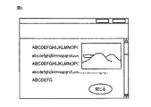
図1は、本実施の形態にかかる画像形成システムの構成の具体例を示す図である。図1を参照して、画像形成システムは、それぞれ表示制御装置を搭載した、複数の画像形成装置1−1A,…1−1Nと複数の情報処理装置3−1A,…3−1Mとがネットワーク4−1で接続された第1のシステムと、複数の画像形成装置1−2A,…1−2Nと複数の情報処理装置3−2A,…3−2Mとがネットワーク4−2で接続された第2のシステムとが、外部ネットワーク5を介して接続してなる。
<System configuration>
FIG. 1 is a diagram showing a specific example of the configuration of the image forming system according to the present embodiment. Referring to FIG. 1, in the image forming system, a plurality of image forming apparatuses 1-1A,... 1-1N and a plurality of information processing apparatuses 3-1A,. 4-1 is connected to a plurality of image forming apparatuses 1-2A, ... 1-2N and a plurality of information processing apparatuses 3-2A, ... 3-2M via a network 4-2. The second system is connected via the
画像形成装置1−1A,…1−1N、1−2A,…1−2Nを代表させて画像形成装置1、情報処理装置3−1A,…3−1M、3−2A,…3−2Mを代表させて情報処理装置3と称する。
The image forming apparatus 1-1A,... 1-1N, 1-2A,... 1-2N is represented by the
ネットワーク4は、LAN(Local Area Network)などの専用回線を用いたネットワーク、インターネット等の一般回線を用いたネットワーク、無線通信によるネットワーク等のいずれであっても構わない。また、外部ネットワーク5も、LANなどの専用回線を用いたネットワーク、インターネット等の一般回線を用いたネットワーク、無線通信によるネットワーク等のいずれであっても構わない。さらに、本画像システムは、外部ネットワーク5を介して他のシステムと接続されていてもよい。
The network 4 may be any one of a network using a dedicated line such as a LAN (Local Area Network), a network using a general line such as the Internet, and a network using wireless communication. Also, the
本実施の形態において、画像形成装置1は、スキャナー、コピー、およびプリンター機能を備えるデジタル複合槻としての機能を有するいわゆるMFP(Multi Function Peripherals)であるものとする。しかしながら、画像形成装置1は、操作部および表示部としてのタッチパネルを有する装置であればMFPに限定されず、スキャナー、コピーなどの他の装置であってもよい。
In the present embodiment, it is assumed that the
画像形成装置1は、スキャンして得られた原稿画像および情報処理装置3から送信されたプリントデータから生成した画像の複写画像を用紙上に形成する装置である。ここで、プリントデータとは、情報処理装置3のオペレーティングシステムやアプリケーションプログラムが発行する描画命令を、プリンタードライバーによって画像形成装置1が処理可能なページ記述言語に変換したページ記述言語による描画命令、またはPDF(Portable Document Format)、TIFF(Tagged Image File Format)、JPEG(Joint Photographic Experts Group)、XPS(XML Paper Specification)等のファイルフォーマットで記述された文書データである。
The
また、スキャンして得られた原稿画像は、画像形成装置において各種設定(ファイル形式、レイアウト設定、解像度設定等)がなされ、ネットワーク4を介して、情報処理装置3等に送信されてもよい。
The original image obtained by scanning may be subjected to various settings (file format, layout setting, resolution setting, etc.) in the image forming apparatus and transmitted to the
情報処理装置3は、一般的なパーソナルコンピューター等であってよい。情報処理装置3は、ユーザーの指示によりプリントデータを生成し、生成したプリントデータを画像形成装置1に送信する。
The
<装置構成>
図2は、画像形成装置1の概略のハードウェア構成を示す模式図である。
<Device configuration>
FIG. 2 is a schematic diagram illustrating a schematic hardware configuration of the
図2を参照して、画像形成装置1は制御部100を含み、制御部100には、装置全体を制御するためのCPU(Central Processing Unit)101、制御プログラムを格納するためのROM(Read Only Memory)102、作業用の記憶領域となるS−RAM(Static Random Access Memory)103、画像形成に関わる各種の設定を記憶するためのバッテリバックアップされたNV−RAM(不揮発性メモリ)104、および時計IC(Integrated Circuit:集積回路)105が含まれる。
Referring to FIG. 2, the
制御部100には、バスを介して、画像読取装置120、各種の入力を行なうためのキーや表示部を備えた、タッチパネルである表示部と数字キー、プリントキー、ログアウトキーなどのキースイッチ群と、操作制御部とを有する操作パネル130、ネットワーク4−1,4−2,5を介して接続された情報処理装置3等の外部の装置との間で各種の情報を送受信するためのネットワークI/F(インターフェース)160、該ネットワークI/F160により受信したプリントデータから複写画像を生成するためのプリンターコントローラー150、および、複写画像を用紙上に形成するための画像出力装置140が接続されている。
The
また、制御部100には、固定記憶装置110がバスを介して接続されている。固定記憶装置110にはたとえばハードディスク装置などが該当する。
A fixed
<動作概要>
図3は、画像形成装置1での全体処理の流れを表わすフローチャートである。図3のフローチャートに表わされた処理は、制御部100に含まれるCPU101がROM102に記憶されているプログラムを読み出してS−RAM103上に展開して実行することによって実現される。図3に示される処理は、電源の投入等により開始される。
<Overview of operation>
FIG. 3 is a flowchart showing the overall processing flow in the
図3を参照して、処理が開始すると、CPU101において、まず、メモリのクリア、標準モードの設定等の初期化処理が行なわれる(ステップS1)。
Referring to FIG. 3, when processing is started,
初期化処理が終了すると、CPU101は、画像形成装置1の操作パネル130上のキースイッチ群、およびタッチパネルである表示部上での操作により、ユーザーからタッチパネルである表示部での表示の制御を必要とする何らかの処理要求(コピー処理、各種の設定処理、表示操作など)がなされたかどうかを確認する(ステップS3)。要求されていなければ(ステップS3でNO)、CPU101はステップS5に進む。
When the initialization process is completed, the
ユーザーから上記の処理要求がなされた場合(ステップS3でYES)、CPU101は、操作パネル130のタッチパネルである表示部での表示処理を行なう(ステップS7)。タッチパネルの処理については、後に詳しく説明する。
When the above processing request is made by the user (YES in step S3), the
ユーザーから上記の処理が要求されていなければ(ステップS3でNO)、CPU101は、ネットワーク4−1,4−2を介して情報処理装置3などの外部の装置から何らかの処理要求(文書のプリント処理、各種の設定処理、など)がされたかどうか確認する(ステップS5)。要求されていなければ(ステップS5でNO)、CPU101はステップS3に戻って前述の処理を繰り返し実行する。
If the above processing is not requested by the user (NO in step S3), the
外部の装置から何らかの処理要求がなされた場合(ステップS5でYES)、CPU101はその要求された処理を実行する(ステップS9)。ここで、その他の処理とは、情報処理装置3から送信されたプリントジョブの処理や、NV−RAM104に記憶されている各種設定の変更処理、などが該当する。外部の装置から要求された処理がすべて終了したら、PU101はステップS3に戻って前述の処理を繰り返し実行する。
When any processing request is made from an external device (YES in step S5), the
画像形成装置1は、操作パネル130のタッチパネルである表示部での表示処理として、ユーザー指示に応じて電子情報に基づく画面を表示する。
The
図4〜図7は、電子情報に基づく画面の表示例を表わした図である。
ここで、電子情報とは、文書、項目の一覧、画像などから表示画面を生成させるためのデータを指す。文書情報の表示画面は、図4に表わされたように、テキストのみで構成されてもよいし、図5に表わされたように、テキストの他、画像や表示やグラフなどが含まれていてもよい。または、項目の一覧情報の表示画面は、図6に表わされたように、リスト形式の一覧画面であってもよいし、図7に表わされたように、項目に対応したキーが配列されたものであってもよい。
4 to 7 are diagrams showing display examples of screens based on electronic information.
Here, the electronic information refers to data for generating a display screen from a document, a list of items, images, and the like. The document information display screen may be composed of only text as shown in FIG. 4, or may include images, displays, graphs, etc. in addition to text as shown in FIG. It may be. Alternatively, the item list information display screen may be a list screen in a list format as shown in FIG. 6, and keys corresponding to items are arranged as shown in FIG. It may be what was done.
画像形成装置1は、電子情報から表示画面を生成し、該表示画面のうちの、操作パネル130のサイズに応じた範囲を表示範囲として特定してその範囲の表示画面を操作パネル130に表示する。
The
画像形成装置1は、操作パネル130に表示画面の一部を表示した状態において、上記ステップS3で表示範囲を移動させるジェスチャー操作であるスクロールジェスチャーを受け付けると、上記ステップS7の操作パネル130の処理として、その操作に従って表示画面のうち操作パネル130に表示させる範囲を変更する処理、つまりスクロール動作を行なう。
When the
図8は、スクロールジェスチャーを表わした図である。
図8を参照して、スクロールジェスチャーは、フリックなどと呼ばれるジェスチャー操作であって、タッチパネルである操作パネル130上の1点(始点)を指等でタッチし、タッチ状態を維持したまま距離L、スライドさせて、異なる1点(終点)で指等を操作パネル130から離してタッチ状態を解除するジェスチャー操作である。
FIG. 8 is a diagram showing a scroll gesture.
Referring to FIG. 8, the scroll gesture is a gesture operation called a flick or the like, and touches one point (start point) on
画像形成装置1は、移動距離Lをタッチされてから指等が離れるまでの時間である操作時間Tで除することで、ジェスチャー操作速度v(v=L/T)を得る。そして、画像形成装置1は、予めジェスチャー操作速度vに対して規定したスクロール速度Vで、表示範囲をスクロールする。
The
図9は、ジェスチャー操作速度に対するスクロール速度の関係の具体例を表わした図である。たとえば、図9に示されたように、スクロール速度Vはジェスチャー操作速度vに比例するもの(V=k×v)として規定されていてもよい。 FIG. 9 is a diagram illustrating a specific example of the relationship between the scroll speed and the gesture operation speed. For example, as shown in FIG. 9, the scroll speed V may be defined as being proportional to the gesture operation speed v (V = k × v).
図10、図11は、スクロールジェスチャーに従う表示の変化の具体例を表わした図であり、具体例として、項目の一覧が表示されているときの表示の変化の具体例を表わしている。このとき、好ましくは、項目の一覧の表示に併せて、表示画面における現在の表示範囲の位置を表わすスクロールバーも表示される。これにより、視覚的に表示範囲の位置を知ることができる。 10 and 11 are diagrams showing specific examples of display changes according to the scroll gesture. As specific examples, FIG. 10 and FIG. 11 show specific examples of display changes when a list of items is displayed. At this time, preferably, a scroll bar indicating the position of the current display range on the display screen is also displayed together with the display of the list of items. Thereby, the position of the display range can be known visually.
また、図10、図11の例では、スクロールジェスチャーとして、上向きにフリックがなされた例が示されている。このとき、表示画面における表示範囲は下方向に移動、つまり、操作パネル130の表示は下方向にスクロールされる。
Further, in the examples of FIGS. 10 and 11, an example in which a flick is made upward as a scroll gesture is shown. At this time, the display range on the display screen moves downward, that is, the display on the
図10を参照して、項目の一覧が表示されているとき上向きにフリックJ1がなされると(図10(A))、画像形成装置1は、フリックJ1の距離Lと時間Tとからジェスチャー操作速度vを算出して、さらに、ジェスチャー操作速度vを用いてスクロール速度Vを算出する。図9の例では、ジェスチャー操作速度vに予め記憶している係数を乗じることでスクロール速度が算出される(V=k×v)。
Referring to FIG. 10, when flick J1 is made upward when the list of items is displayed (FIG. 10A),
このとき、画像形成装置1は、1回のスクロール動作での移動距離として予め規定された所定距離だけ表示範囲をスクロールすると、表示範囲が電子情報から生成された表示画面の端部に達するか否かを確認する。所定距離としては、たとえば表示画面がテキストの場合には1行分、項目の一覧である場合には1項目分、画像の場合には10pixlなどが挙げられる。
At this time, when the
たとえば、下方向にスクロールさせるジェスチャー操作を受け付けた場合には、画像形成装置1は、上記所定距離だけ表示範囲を下方向にスクロールすると表示画面の下端に達するか否かを確認し、上方向にスクロールさせるジェスチャー操作を受け付けた場合には、同様に表示画面の上端に達するか否かを確認する。そして、端部に到達しない場合には、画像形成装置1は、ジェスチャー操作に従って表示をスクロールする。
For example, when a gesture operation for scrolling downward is received, the
図10(A)の例では、表示範囲が表示画面のかなり上方であるため、画像形成装置1は、下方向にスクロールしても表示画面の下端には達しないと判断する。そのため、算出されたスクロール速度で、所定距離、下方向にスクロールする(図10(B))。図10(B)の画面において上向きにフリックJ2がなされると、同様にして、下方向のスクロールが行なわれる。
In the example of FIG. 10A, since the display range is considerably above the display screen, the
このとき、好ましくは、画像形成装置1は1回の操作パネル130の処理であるスクロール動作中で、スクロール速度を変化させる。詳しくは、画像形成装置1は、スクロールを開始してから最大スクロール速度となるまでスクロール速度を加速し、最大スクロール速度に到達した後は、スクロール速度が0となる(停止する)まで徐々に減速する。
At this time, preferably, the
図12は、1回のスクロール動作でのスクロール速度の推移の具体例を表わした図である。図12に示されるように、画像形成装置1は、たとえば図9の関係を用いてジェスチャー操作速度vから算出したスクロール速度を最大スクロール速度として、スクロール動作の開始から最大スクロール速度まで加速して、その後、0となるまでスクロール速度を減速する。
FIG. 12 is a diagram illustrating a specific example of transition of scroll speed in one scroll operation. As shown in FIG. 12, the
下方向へのスクロールを繰り返した結果、表示範囲が画面下端に到達すると、または、表示範囲が画面下端にある状態でさらに下向きのフリックを受け付けると、画像形成装置1は、図11(A)のように、いったん、表示画面の下端を表示範囲として表示する。
As a result of repeated scrolling in the downward direction, when the display range reaches the lower end of the screen, or when a further downward flick is received in a state where the display range is at the lower end of the screen, the
その後、表示画面の下端を操作パネル130の画面の下端に固定した状態で、表示範囲を、スクロール方向と逆方向である上方向に徐々に拡大する(引き延ばす)ように変形を開始する(図11(B))。変形開始の後、画像形成装置1は、予め規定した時間内で、スクロール方向と逆方向である上方向の変形量を、予め規定した最大の変形量(倍率)となるまで増加させた後(図11(C))、徐々に減少させて図11(B)の状態を経て変形量0の図11(A)の画面まで変化させる。
Thereafter, in a state where the lower end of the display screen is fixed to the lower end of the screen of the
なお、このとき、好ましくは、CPU101は、表示範囲にある文字や記号等のオブジェクトに対しては上記変形量を適用せずに、変形させない。これにより、表示が拡大、縮小して変形された場合であっても、ユーザーの読みやすさを確保することができる。なお、この変形方法は、後述する変形例でも行なわれてよい。
At this time, preferably, the
上記変形量は、スクロール速度から算出される。スクロール速度Vはジェスチャー操作速度vから算出されるため、変形量もまた、ジェスチャー操作速度vから算出されると言うこともできる。すなわち、変形量Mはジェスチャー操作速度vの関数で表わすことができる(M=f(v))。 The deformation amount is calculated from the scroll speed. Since the scroll speed V is calculated from the gesture operation speed v, it can be said that the deformation amount is also calculated from the gesture operation speed v. That is, the deformation amount M can be expressed as a function of the gesture operation speed v (M = f (v)).
図13は、スクロール速度に対する変形量の関係の具体例を表わした図である。たとえば、図13に示されたように、変形量Mはスクロール速度Vに比例するものとして規定されていてもよい(M=a×V)。この場合、画像形成装置1は、ジェスチャー操作速度から算出されたスクロール速度から、さらに変形量を算出する。
FIG. 13 is a diagram illustrating a specific example of the relationship of the deformation amount with respect to the scroll speed. For example, as shown in FIG. 13, the deformation amount M may be defined as being proportional to the scroll speed V (M = a × V). In this case, the
1回の変形動作での変形量の変化は、時間経過によって推移する。すなわち、変形量の変化率yは、変形開始からの経過時間tの関数で表わすことができる(y=G(t))。 The change of the deformation amount in one deformation operation changes with time. That is, the deformation rate change rate y can be expressed as a function of the elapsed time t from the start of deformation (y = G (t)).
図14は、1回の変形動作での変形量の変化の推移の具体例を表わした図である。図14に示されるように、画像形成装置1は、たとえば図13の関係を用いてスクロール速度から算出した変形量を最大変形量として、変形開始から最大変形量まで変形量を増加して、その後、変形量が0、すなわち元の状態となるまで変形量を減少する。
FIG. 14 is a diagram illustrating a specific example of the transition of the change in the deformation amount in one deformation operation. As shown in FIG. 14, the
画像形成装置1は、表示を変形させる際には、そのときの表示範囲の画像データを、図14に表わされたような変化率yでスクロール方向に変形量0から最大変形量Mを経て変形量0となるように所定の時間間隔で変化させ続ける。そして、その所定の時間間隔で得られた変形後の画像データから、スクロールで達した表示画面の端部の位置を固定して操作パネル130のサイズに応じた表示範囲を特定し、その範囲を操作パネル130に逐次、表示させる。
When the
これにより、下向きのフリックによって表示範囲が表示画面の下端に達する場合、表示が、図11(A)→図11(B)→図11(C)→図11(B)→図11(A)と変化する。 Thus, when the display range reaches the lower end of the display screen by a downward flick, the display is changed from FIG. 11 (A) → FIG. 11 (B) → FIG. 11 (C) → FIG. 11 (B) → FIG. And change.
このとき、好ましくは、画像形成装置1は、項目の一覧と共に表示されているスクロールバーの、現在の表示範囲の表示画面における位置や、表示範囲の表示画面全体に占める割合などを表現するマーク(ノブ)を、図11(B)、図11(C)に表わされたように、変形量と対応させて変形させる。これにより、ユーザーは、視覚的に、どのように変形しているかを知ることができる。
At this time, preferably, the
なお、上述した図10〜図11を用いた例では、上下向きにフリックがなされて上下方向にスクロールがなされる例が示されているが、左右方向も同様である。 In the example using FIGS. 10 to 11 described above, an example in which flicking is performed in the vertical direction and scrolling in the vertical direction is shown, but the same applies to the horizontal direction.
図22は、タッチパネルでの表示範囲が表示画面の端部に到達する前後での、表示画面と表示範囲との関係を説明するための図であって、図22(A)は表示画面の端部到達前、図22(B)は端部到達後を表わしている。 FIG. 22 is a diagram for explaining the relationship between the display screen and the display range before and after the display range on the touch panel reaches the end of the display screen. FIG. Before reaching the part, FIG. 22 (B) shows after reaching the end.
なお、これらにも表わされているように、「表示画面」とは電子情報に基づいて生成される表示用データ全体の画像を表わし、「表示範囲」は、該表示用データ上での、タッチパネルに表示される範囲を表わす。図22の例では、スクロール方向に辺Aおよび辺Bをそれぞれ上端および下端とする矩形が、電子情報から生成される表示用データ全体の画像である表示画面を表わしており、そのうちの、辺aおよび辺bをそれぞれ上端および下端とする矩形がタッチパネルでの表示範囲を表わしている。 As shown in these figures, the “display screen” represents an image of the entire display data generated based on the electronic information, and the “display range” represents the display data on the display data. Represents the range displayed on the touch panel. In the example of FIG. 22, a rectangle having sides A and B as the upper and lower ends in the scroll direction represents a display screen that is an image of the entire display data generated from the electronic information. And the rectangle which makes edge | side b each an upper end and a lower end represents the display range in a touchscreen.
図22(A)の端部到達前においては、辺aおよび辺bで挟まれるタッチパネルでの表示範囲は、辺Aおよび辺Bで挟まれる表示用データ全体の画像中の、いずれの端部にも達していない。 Before reaching the end of FIG. 22A, the display range on the touch panel sandwiched between side a and side b is at any end in the image of the entire display data sandwiched between side A and side B. Has not reached.
図22(A)の状態から下方向のスクロールが指示されることでタッチパネルでの表示範囲が表示画面の下方向に移動していき、図22(B)に表わされたように、表示範囲の下端である辺bが表示画面の下端である辺Bに一致する位置まで達する。この状態が、タッチパネルでの表示範囲が表示画面の下端に達した状態を表わしている。上端に達した状態では、表示範囲の上端である辺aが表示画面の上端である辺Aに一致することになる。 When a downward scroll is instructed from the state of FIG. 22A, the display range on the touch panel moves downward, and the display range as shown in FIG. 22B. Reaches a position where side b, which is the lower end of, coincides with side B, which is the lower end of the display screen. This state represents a state where the display range on the touch panel has reached the lower end of the display screen. In a state where the upper end has been reached, the side a that is the upper end of the display range coincides with the side A that is the upper end of the display screen.
画像形成装置1では、表示範囲が表示画面の端部に達すると、図11(A)→図11(B)→図11(C)→図11(B)→図11(A)のように表示される画像が変形する。表示画面の下端までスクロールが達した図22(B)の例では、図示されたように、表示範囲の下端である辺bは、表示画面の下端である辺Bと一致した状態で固定される。一方、表示範囲の上端である辺aは、変形に伴って移動することになる。図11(A)→図11(B)→図11(C)→図11(B)→図11(A)のように表示される画像が変形するときには、辺aは、いったん図22(B)のように配置された後に徐々に下端側に移動した後、また、図22(B)の状態に戻る。
In the
この例の場合、辺aが移動することで変化するいずれの表示範囲も、タッチパネルの表示領域における表示内容と完全に一致する。ここでの「表示領域」とは、タッチパネルの物理的概念に相当する。 In the case of this example, any display range that changes as the side a moves completely matches the display content in the display area of the touch panel. The “display area” here corresponds to the physical concept of the touch panel.
なお、図示されていないものの、スクロールの結果、表示範囲が表示画面の上端に達した場合には、この例とは逆に、表示範囲の上端である辺aが表示画面の上端の辺Aに一致した位置で固定し、下端である辺bが変形に伴って移動することになる。 Although not shown, when the display range reaches the upper end of the display screen as a result of scrolling, the side a which is the upper end of the display range is changed to the upper end side A of the display screen, contrary to this example. The side b, which is the lower end, is fixed and moved at the same position as the deformation.
<機能構成>
図15は、上記動作を行なうための画像形成装置1の機能構成の具体例を示すブロック図である。図15の各機能は、CPU101がROM102に記憶されている表示制御プログラムを読み出してS−RAM103上に展開して実行することによって主にCPU101上に形成される機能である。しかしながら、少なくとも一部が、電気回路等のハードウェア構成によって実現されてもよい。
<Functional configuration>
FIG. 15 is a block diagram illustrating a specific example of a functional configuration of the
図15を参照して、固定記憶装置110等の記憶装置に、電子情報に基づく表示画面を記憶するための記憶領域である表示画面記憶部301が設けられる。
Referring to FIG. 15, a storage device such as fixed
さらに図15を参照して、CPU101は、タッチパネルである操作パネル130がタッチされることによる指示入力を受け付けるための入力部201と、操作パネル130に対するジェスチャー操作がフリックなどのスクロールジェスチャーであることを検出するための検出部202と、スクロールジェスチャーに基づいてスクロール方向を特定し、表示画面のうち、スクロール後の表示範囲を特定するための表示範囲特定部203と、表示範囲を記憶するための表示範囲記憶部204と、表示範囲が表示画面の端部に達しているか否かを判断するための判断部205と、スクロールジェスチャーであるジェスチャー操作からジェスチャー操作速度v(v=L/T)を算出するための操作速度算出部206と、ジェスチャー操作速度vからスクロール速度を算出するためのスクロール速度算出部207と、操作パネル130の処理としてスクロール処理を実行するためのスクロール処理部208と、スクロール速度から変形量Mを算出するための変形量算出部209と、変形量Mを最大変形量として所定時間での変形量の変化率yを算出するための変化率算出部210と、スクロール後の表示範囲が表示画面の端部に達している場合に、変形量Mを最大変形量として変化率yで変形量を変化させつつ表示を変形させる変形処理を行なうための変形処理部211とを含む。
Further, referring to FIG. 15,
<動作フロー>
図16は、上記ステップS7の操作パネル130のタッチパネルである表示部での表示処理の流れを表わすフローチャートである。図16のフローチャートに表わされる動作は、CPU101がROM102に記憶されている表示制御プログラムを読み出してS−RAM103上に展開して実行し、図15の各機能を発揮させることによって実現される。
<Operation flow>
FIG. 16 is a flowchart showing the flow of display processing on the display unit which is the touch panel of
図16を参照して、ユーザーからの処理要求を表わすジェスチャー操作がスクロールジェスチャーであった場合(ステップS101でYES)、CPU101は、移動距離Lをタッチされてから指等が離れるまでの時間である操作時間Tで除することで、ジェスチャー操作速度v(v=L/T)を算出する(ステップS103)。なお、スクロールジェスチャーでなかった場合には、処理要求に応じた他の処理を行なう(ステップS105)。
Referring to FIG. 16, when the gesture operation representing the processing request from the user is a scroll gesture (YES in step S <b> 101),
CPU101は、さらに、予め記憶している図9のような関係式を用いて、上記ステップS103で算出したジェスチャー操作速度からスクロール速度を算出し、そのスクロール速度を最大スクロール速度に設定する(ステップS107)。
The
次に、CPU101は、予め規定されているスクロール量、現在の表示をスクロールすると、表示画面の端部に到達するか否かを判断する(ステップS109)。ここでは、CPU101は、予め、表示画面がテキストの場合には1行分、項目の一覧である場合には1項目分、画像の場合には10pixlなどを1回のスクロール量として記憶しておき、表示画面に応じて、そのスクロール量、スクロールしたときに、表示範囲が表示画面の端部に到達するか否かを判断する。
Next, the
スクロールの結果、表示範囲が表示画面の端部には到達しない場合には(ステップS109でNO)、CPU101は、スクロール処理を行なう(ステップS111)。ここでのスクロール処理は通常のスクロール処理である。一例として、スクロールを開始すると、予め規定された時間内で、上記ステップS107で設定された最大スクロール速度を経てスクロール速度が0となるまで、図12のような推移でスクロール速度を変化させて、規定されたスクロール量分、表示範囲を移動させて表示を更新する。
If the display range does not reach the end of the display screen as a result of scrolling (NO in step S109), the
一方、スクロールの結果、表示範囲が表示画面の端部に到達すると判断された場合(ステップS109でYES)、CPU101は、上記ステップS107で算出されたスクロール速度(または上記ステップS103で算出されたジェスチャー速度)から変形量を算出し、その変形量を最大変形量に設定する(ステップS113)。そして、その変形量を用いて変形処理を行なう(ステップS115)。
On the other hand, when it is determined that the display range reaches the end of the display screen as a result of scrolling (YES in step S109), the
図17は、上記ステップS115での変形処理の流れを表わすフローチャートである。
図17を参照して、CPU101は、上記スクロールの結果到達する表示画面の端部を表示範囲に設定し(ステップS201)、変形処理開始時には変形率を0とする(ステップS203)。そして、CPU101は、その変形率(=0)を適用して表示範囲の画像を変形させる(ステップS205)。CPU101は、変形後の画像から表示範囲を設定し(ステップS207)、その表示範囲を表示する(ステップS209)。
FIG. 17 is a flowchart showing the flow of the deformation process in step S115.
Referring to FIG. 17,
変形処理開始時には変形率が0であるため、この段階では、図11(A)に表わされたような、表示画面の端部が操作パネル130に表示されることになる。
Since the deformation rate is 0 at the start of the deformation process, the edge of the display screen as shown in FIG. 11A is displayed on the
その後、CPU101は、変形率を図14のように時間経過に従って増加させ(ステップS211)、変形率が上記ステップS113で設定した最大変形率に到達するまで(ステップS213でNO)、上記ステップS205〜S211を繰り返す。
Thereafter, the
これにより、変形処理開始から図11(A)→図11(B)→図11(C)と、最大変形率に達するまでスクロール方向に表示が拡大する。 As a result, the display is enlarged in the scroll direction from the start of the deformation process until the maximum deformation rate is reached, as shown in FIG. 11 (A) → FIG. 11 (B) → FIG.
最大変形率に達すると(ステップS213でYES)、CPU101は、変形率が0に戻るまで(ステップS223でNO)、変形率を図14のように時間経過に従って減少させる(ステップS215)。そして、CPU101は、上記ステップS205〜S211と同様の処理を繰り返す(ステップS217〜S221)。
When the maximum deformation rate is reached (YES in step S213), the
これにより、最大変形率に達した後、→図11(C)→図11(B)→図11(A)と、変形率が元の0に戻るまで拡大した表示がスクロール方向に縮小する。 As a result, after reaching the maximum deformation rate, the enlarged display is reduced in the scroll direction until the deformation rate returns to 0, as shown in FIG. 11C → FIG. 11B → FIG. 11A.
変形率が0に達すると(ステップS223でYES)、CPU101は、一連の処理を終了する。
When the deformation rate reaches 0 (YES in step S223), the
<実施の形態の効果>
画像形成装置1において上記動作が行なわれることで、フリックなどのジェスチャー操作によって項目の一覧表示などをスクロールさせたとき、表示画面の端部(上端、下端)に到達したときに、端部が表示されたまま、いったん、表示がスクロール方向に伸びて、また元に戻るように変形して表示される。
<Effect of Embodiment>
By performing the above-described operation in the
このため、ユーザーは、表示画面がまだスクロール方向に続くのではないかと誤解したり、表示の不具合でないかと誤解したりすることなく、表示画面の端部に達したことを容易に知ることができる。 For this reason, the user can easily know that the end of the display screen has been reached without misunderstanding that the display screen still continues in the scroll direction or not being a display defect. .
<第1の変形例>
上の例では、ジェスチャー操作速度から得られたスクロール速度に応じて変形量が算出され、その変形量を最大変形量とした時間変化に応じた変化率の変化量が、表示範囲の画像全体に適用されるものとしている。つまり、上の例では、表示範囲のどの位置でも変形量が同じとされている。
<First Modification>
In the above example, the deformation amount is calculated according to the scroll speed obtained from the gesture operation speed, and the change amount of the change rate according to the time change with the deformation amount as the maximum deformation amount is applied to the entire image in the display range. It shall be applied. That is, in the above example, the deformation amount is the same at any position in the display range.
他の例として、図18に表わされたように、表示範囲のスクロール方向の位置に応じて変形量を変化させてもよい。一例として、図18の例では、表示画面の端部の変形量を最大として、スクロール方向に当該端部から離れるほど変形量が小さくなるように変形された例が表わされている。 As another example, as shown in FIG. 18, the amount of deformation may be changed according to the position of the display range in the scroll direction. As an example, the example of FIG. 18 shows an example in which the amount of deformation at the end of the display screen is maximized and the amount of deformation is reduced as the distance from the end in the scroll direction increases.
この場合、画像形成装置1のCPU101は、一例として、予め表示範囲のスクロール方向に並ぶ変形領域を複数設定しておき、変形時の変形量を最も端部に近い変形領域に適用し、当該変形領域からスクロール方向に離れる変形領域ほど、予め規定された割合でその変形時の変形量を変化させて(減じて)適用する。他の例として、CPU101は、変形時の変形量を表示範囲にある表示画面端部からスクロール方向に向けて連続的に変化させた上で、その位置の画像に適用してもよい。これにより、設定された変形領域ごとに、異なる変形量で変形させることができる。
In this case, as an example, the
また、図18の例では、表示画面の端部の変形量を最大として、スクロール方向に当該端部から離れるほど変形量が小さくなるように変形しているが、これとは逆に、表示範囲の、表示画面の端部から最も遠い側の変形量を最大として、スクロール方向に当該端部に近付くほど変形量が小さくなるように変形させてもよい。 Further, in the example of FIG. 18, the deformation amount at the end portion of the display screen is maximized, and the deformation amount is decreased as the distance from the end portion in the scroll direction is increased. Alternatively, the deformation amount on the side farthest from the end portion of the display screen may be maximized, and the deformation amount may be reduced so as to approach the end portion in the scroll direction.
スクロールの結果、表示画面端部に達したときに画像形成装置1が上述のように変形させることで、表示画面端部からの距離に応じて変形量がことなって変形して表示されるため、ユーザーは一目で表示画面端部に達したことを把握できる。
As a result of the scrolling, the
特に、図18に表わされたように表示画面の端部の変形量を最大として、スクロール方向に当該端部から離れるほど変形量が小さくなるように変形されることで、スクロールによる慣性力のかかる点に近い位置ほど変形量が大きくなるような、物理現象に似た表示となるため、ユーザーはより把握しやすくなる。 In particular, as shown in FIG. 18, the amount of deformation at the end of the display screen is maximized, and the amount of deformation due to scrolling is reduced so that the amount of deformation decreases as the distance from the end in the scroll direction increases. Since the display is similar to a physical phenomenon in which the amount of deformation increases as the position is closer to such a point, the user can more easily grasp the display.
<第2の変形例>
表示画面が例示されたように項目の一覧など、スクロール方向に直行する方向のオブジェクトの配列(行)がスクロール方向に配置されるものである場合、画像形成装置1は、図19に表わされたように、オブジェクトの配列自体のサイズは変形させず、配列と配列との間を変形させるようにしてもよい。
<Second Modification>
When the array (rows) of objects in the direction orthogonal to the scroll direction is arranged in the scroll direction, such as a list of items as shown in the display screen, the
この場合、画像形成装置1のCPU101は、予め、オブジェクトごとに位置やサイズを記憶しておき、その配列を特定することができる。そして、変形処理を行なう際に、配列に対しては変形量を適用することなく、その他領域に対して変形量を適用することで実現することができる。このようにすることでも、ユーザーの見やすさを確保することができる。
In this case, the
<第3の変形例>
第3の変形例として、すでに表示範囲が表示画面端部に到達して操作パネル130に表示されている状態において、端部に向かう方向にさらにスクロールジェスチャーを受け付けた場合に、画像形成装置1は、すでに表示画面端部に達していることが分かるような表示を行なう。
<Third Modification>
As a third modification, in a state where the display range has already reached the end of the display screen and is displayed on the
図20は、第3の変形例での、スクロールジェスチャーに従う表示の変化の具体例を表わした図であり、具体例として、項目の一覧の画面の下端が表示されているときの表示の変化の具体例を表わしている。 FIG. 20 is a diagram showing a specific example of the display change according to the scroll gesture in the third modification. As a specific example, the display change when the lower end of the item list screen is displayed is shown. A specific example is shown.
図20(A)を参照して、この状態において上向きにフリックJ3がなされると、画像形成装置1は、フリックJ3の位置を含むスクロール方向に直交する直線を変形境界として、当該境界よりも画面端部側を変形領域、画面端部に遠い側を移動領域として特定する。そして、変形領域の画像を拡大すると共に、移動領域の画像をスクロール方向と逆向きに移動させる(図20(B))。
Referring to FIG. 20A, when flick J3 is made upward in this state,
拡大領域の拡大方法は、上述の拡大処理での方法と同じ方法とすることができる。画像形成装置1は、拡大処理によって拡大領域のサイズが拡大した分移動領域の表示範囲を狭め、拡大領域のサイズが拡大した分スクロール方向と逆向きに移動させる。
The enlargement method of the enlargement region can be the same as the method in the enlargement process described above. The
図20の例では、表示画面の下端が表示された状態で下方向のスクロールが指示されているため(図20(A))、画像形成装置1は、フリックJ3の位置を変形境界として、当該変形境界より下方を拡大領域とし、変形境界より上方を移動領域とする。そして、画像形成装置1は、拡大領域としたフリックJ3の位置より下方の領域を上方向に上述の演算によって算出された最大変形量となるまで変形(拡大)すると共に、それによって変形領域が上方に移動するのに連動して、移動領域を上方に移動させる。
In the example of FIG. 20, since the scrolling in the downward direction is instructed with the lower end of the display screen displayed (FIG. 20A), the
上述と同様に、画像形成装置1は、拡大領域を、変形率0から最大変形量となるまで時間経過に従って変形量を変化させて拡大し、その後、変形率が0に戻るまで変形量を変化させて縮小する。これにつれて、移動領域はいったん上方に移動した後、下方に戻る。また、移動領域の表示範囲も、元の表示範囲から徐々に減り、最小になってから、また、元の状態に戻る。
In the same manner as described above, the
図21は、第3の変形例での変形処理の流れの一部を表わしたフローチャートである。
図21を参照して、画像形成装置1のCPU101は、表示画面の端部を操作パネル130に表示中に、その端部に向かう方向にスクロールの指示を受け付けると(ステップS301でYES)、ジェスチャー操作の位置に基づいて変形境界を特定する(ステップS303)。
FIG. 21 is a flowchart showing a part of the flow of deformation processing in the third modification.
Referring to FIG. 21, when
CPU101は、変形境界よりも表示画面端部側の変形領域を拡大処理する(ステップS305)。ここでの処理は、上記した変形処理と同様とすることができる。
The
一方、CPU101は、上記ステップS305での変形後の変形領域のサイズに応じて変形境界よりも表示画面端部から遠い側の移動領域の表示範囲を特定する(ステップS307)。これは、一例として、予め記憶している操作パネル130の表示サイズから上記ステップS305での変形後の変形領域のサイズを差し引くことで得られる。
On the other hand, the
CPU101は、上記ステップS305の変形後の変形領域と、上記ステップS307で特定した移動領域の表示範囲とを合わせて、操作パネル130に表示する。
The
以降、上記したように、変形率に時間変化に応じて変形処理および移動領域の表示範囲の特定を繰り返すことで、CPU101は、図20のような画面変化をさせる。
Thereafter, as described above, the
このような動作が行なわれることで、表示画面端部に達した状態でスクロール操作を行なうと、クロール操作を行なった部分から端部までの範囲がスクロール動作に応じていったん伸びた後に元に戻るように表示される。 By performing such an operation, if the scroll operation is performed in a state where the display screen has reached the end of the display screen, the range from the portion where the crawl operation has been performed to the end is once extended according to the scroll operation and then returned to the original state. Is displayed.
このため、ユーザーは、表示画面の端部にすでに達していることを、誤解なく、視覚的に把握することができる。 For this reason, the user can grasp visually that it has already reached the end of the display screen without misunderstanding.
さらに、上述の処理を画像形成装置1のCPU101に実行させて、タッチパネルの表示を制御するための制御装置として機能させるプログラムを提供することもできる。このようなプログラムは、コンピュータに付属するフレキシブルディスク、CD−ROM(Compact Disk-Read Only Memory)、ROM、RAMおよびメモリカードなどのコンピュータ読取り可能な記録媒体にて記録させて、プログラム製品として提供することもできる。あるいは、コンピュータに内蔵するハードディスクなどの記録媒体にて記録させて、プログラムを提供することもできる。また、ネットワークを介したダウンロードによって、プログラムを提供することもできる。
Furthermore, it is possible to provide a program that causes the
なお、本発明にかかるプログラムは、コンピュータのオペレーティングシステム(OS)の一部として提供されるプログラムモジュールのうち、必要なモジュールを所定の配列で所定のタイミングで呼出して処理を実行させるものであってもよい。その場合、プログラム自体には上記モジュールが含まれずOSと協働して処理が実行される。このようなモジュールを含まないプログラムも、本発明にかかるプログラムに含まれ得る。 The program according to the present invention is a program module that is provided as a part of a computer operating system (OS) and calls necessary modules in a predetermined arrangement at a predetermined timing to execute processing. Also good. In that case, the program itself does not include the module, and the process is executed in cooperation with the OS. A program that does not include such a module can also be included in the program according to the present invention.
また、本発明にかかるプログラムは他のプログラムの一部に組込まれて提供されるものであってもよい。その場合にも、プログラム自体には上記他のプログラムに含まれるモジュールが含まれず、他のプログラムと協働して処理が実行される。このような他のプログラムに組込まれたプログラムも、本発明にかかるプログラムに含まれ得る。 The program according to the present invention may be provided by being incorporated in a part of another program. Even in this case, the program itself does not include the module included in the other program, and the process is executed in cooperation with the other program. Such a program incorporated in another program can also be included in the program according to the present invention.
提供されるプログラム製品は、ハードディスクなどのプログラム格納部にインストールされて実行される。なお、プログラム製品は、プログラム自体と、プログラムが記録された記録媒体とを含む。 The provided program product is installed in a program storage unit such as a hard disk and executed. The program product includes the program itself and a recording medium on which the program is recorded.
今回開示された実施の形態はすべての点で例示であって制限的なものではないと考えられるべきである。本発明の範囲は上記した説明ではなくて特許請求の範囲によって示され、特許請求の範囲と均等の意味および範囲内でのすべての変更が含まれることが意図される。 The embodiment disclosed this time should be considered as illustrative in all points and not restrictive. The scope of the present invention is defined by the terms of the claims, rather than the description above, and is intended to include any modifications within the scope and meaning equivalent to the terms of the claims.
1,1−1A,…1−1N,1−2A,…1−2N 画像形成装置、3,3−1A,…3−1M,3−2A,…3−2M 情報処理装置、4 ネットワーク、5 外部ネットワーク、100 制御部、102 ROM、103 S−RAM,104 NV−RAM、105 時計IC、110 固定記憶装置、120 画像読取装置、130 操作パネル、140 画像出力装置、150 プリンターコントローラー、160 ネットワークI/F、201 入力部、202 検出部、203 表示範囲特定部、204 表示範囲記憶部、205 判断部、206 操作速度算出部、207 スクロール速度算出部、208 スクロール処理部、209 変形量算出部、210 変化率算出部、211 変形処理部、301 表示画面記憶部。 1, 1-1A, ... 1-1N, 1-2A, ... 1-2N Image forming apparatus, 3, 3-1A, ... 3-1M, 3-2A, ... 3-2M Information processing apparatus, 4 network, 5 External network, 100 control unit, 102 ROM, 103 S-RAM, 104 NV-RAM, 105 clock IC, 110 fixed storage device, 120 image reading device, 130 operation panel, 140 image output device, 150 printer controller, 160 network I / F, 201 input unit, 202 detection unit, 203 display range specifying unit, 204 display range storage unit, 205 determination unit, 206 operation speed calculation unit, 207 scroll speed calculation unit, 208 scroll processing unit, 209 deformation amount calculation unit, 210 change rate calculation unit, 211 deformation processing unit, 301 display screen storage unit.
Claims (13)
電子情報に基づいて生成される表示画面を記憶するための記憶手段と、
前記タッチパネルに対して、前記タッチパネルの表示に対するスクロール操作がなされたことを検出するための検出手段と、
前記表示画面のうちの前記タッチパネルに表示されている表示範囲が、前記スクロール操作で指示されるスクロール方向に移動させても前記表示画面の端部に到達しない場合に、前記表示範囲を前記スクロール方向に移動させて前記タッチパネルに表示させるためのスクロール処理手段と、
前記スクロール方向に移動させることで前記表示範囲が前記表示画面の端部に到達する場合に、前記表示画面の端部を、前記タッチパネルの表示領域における前記スクロール方向の端部とし、前記表示画面に表示される少なくとも一部の画像オブジェクトを前記スクロール方向に変形させて前記タッチパネルに表示させるための変形処理手段とを備えるとともに、
前記変形処理手段は、前記表示画面の端部において前記画像オブジェクトが拡大して変形されるのに応じて、前記タッチパネルに表示されるスクロールバーのノブを拡大して変形させる、表示装置。 A display device having a touch panel,
Storage means for storing a display screen generated based on electronic information;
Detection means for detecting that a scroll operation on the display of the touch panel has been performed on the touch panel;
When the display range displayed on the touch panel of the display screen does not reach the end of the display screen even if the display range is moved in the scroll direction indicated by the scroll operation, the display range is changed to the scroll direction. Scroll processing means for moving the display to display on the touch panel;
When the display range reaches the end of the display screen by moving in the scroll direction, the end of the display screen is set as the end in the scroll direction in the display area of the touch panel. A deformation processing means for deforming at least a part of the displayed image object in the scroll direction and displaying the image object on the touch panel;
The deformation processing means enlarges and deforms a knob of a scroll bar displayed on the touch panel in response to the image object being enlarged and deformed at an end of the display screen.
電子情報に基づいて生成される表示画面を記憶するための記憶手段と、
前記タッチパネルに対して、前記タッチパネルの表示に対するスクロール操作がなされたことを検出するための検出手段と、
前記表示画面のうちの前記タッチパネルに表示されている表示範囲が、前記スクロール操作で指示されるスクロール方向に移動させても前記表示画面の端部に到達しない場合に、前記表示範囲を前記スクロール方向に移動させて前記タッチパネルに表示させるためのスクロール処理手段と、
前記スクロール方向に移動させることで前記表示範囲が前記表示画面の端部に到達する場合に、前記表示画面の端部を、前記タッチパネルの表示領域における前記スクロール方向の端部とし、前記表示画面に表示される複数の画像オブジェクトの間隔が変化するように前記表示画面を前記スクロール方向に変形させて前記タッチパネルに表示させるための変形処理手段とを備えるとともに、
前記変形処理手段は、前記表示画面の端部において前記間隔が拡大して変形されるのに応じて、前記タッチパネルに表示されるスクロールバーのノブを拡大して変形させる、表示装置。 A display device having a touch panel,
Storage means for storing a display screen generated based on electronic information;
Detection means for detecting that a scroll operation on the display of the touch panel has been performed on the touch panel;
When the display range displayed on the touch panel of the display screen does not reach the end of the display screen even if the display range is moved in the scroll direction indicated by the scroll operation, the display range is changed to the scroll direction. Scroll processing means for moving the display to display on the touch panel;
When the display range reaches the end of the display screen by moving in the scroll direction, the end of the display screen is set as the end in the scroll direction in the display area of the touch panel. A deformation processing means for deforming the display screen in the scroll direction so as to change the interval between the plurality of image objects to be displayed and causing the touch panel to be displayed.
The deformation processing means enlarges and deforms a knob of a scroll bar displayed on the touch panel in response to the interval being enlarged and deformed at an end of the display screen.
前記タッチパネルに対して、前記タッチパネルの表示に対するスクロール操作がなされたことを検出するステップと、
前記表示画面のうちの前記タッチパネルに表示されている表示範囲が、前記スクロール操作で指示されるスクロール方向に移動させると、前記表示画面の端部に到達するか否かを判断するステップと、
前記スクロール方向に移動させても前記表示範囲が前記表示画面の端部に到達しない場合に、前記表示範囲を前記スクロール方向に移動させて前記タッチパネルに表示させるステップと、
前記スクロール方向に移動させることで前記表示範囲が前記表示画面の端部に到達する場合に、前記表示画面の端部を、前記タッチパネルの表示領域における前記スクロール方向の端部とし、前記表示画面に表示される少なくとも一部の画像オブジェクトを前記スクロール方向に変形させて前記タッチパネルに表示させるステップとを前記コンピュータに実行させ、
前記変形させて前記タッチパネルに表示させるステップは、前記表示画面の端部において前記画像オブジェクトが拡大して変形されるのに応じて、前記タッチパネルに表示されるスクロールバーのノブを拡大して変形させる、表示制御プログラム。 A program for causing a computer to execute processing for controlling display of a display screen generated based on electronic information on a touch panel,
Detecting that a scroll operation on the display of the touch panel has been performed on the touch panel;
Determining whether or not a display range displayed on the touch panel of the display screen reaches an end of the display screen when moved in a scroll direction instructed by the scroll operation;
When the display range does not reach the end of the display screen even when moved in the scroll direction, the display range is moved in the scroll direction and displayed on the touch panel;
When the display range reaches the end of the display screen by moving in the scroll direction, the end of the display screen is set as the end in the scroll direction in the display area of the touch panel. Causing the computer to execute a step of deforming at least a part of the displayed image object in the scroll direction and displaying the image object on the touch panel,
The step of deforming and displaying on the touch panel enlarges and deforms a knob of a scroll bar displayed on the touch panel in response to the image object being enlarged and deformed at an end of the display screen. , Display control program.
前記タッチパネルに対して、前記タッチパネルの表示に対するスクロール操作がなされたことを検出するステップと、
前記表示画面のうちの前記タッチパネルに表示されている表示範囲が、前記スクロール操作で指示されるスクロール方向に移動させると、前記表示画面の端部に到達するか否かを判断するステップと、
前記スクロール方向に移動させても前記表示範囲が前記表示画面の端部に到達しない場合に、前記表示範囲を前記スクロール方向に移動させて前記タッチパネルに表示させるステップと、
前記スクロール方向に移動させることで前記表示範囲が前記表示画面の端部に到達する場合に、前記表示画面の端部を、前記タッチパネルの表示領域における前記スクロール方向の端部とし、前記表示画面に表示される複数の画像オブジェクトの間隔が変化するように前記表示画面を前記スクロール方向に変形させて前記タッチパネルに表示させるステップとを前記コンピュータに実行させ、
前記変形させて前記タッチパネルに表示させるステップは、前記表示画面の端部において前記間隔が拡大して変形されるのに応じて、前記タッチパネルに表示されるスクロールバーのノブを拡大して変形させる、表示制御プログラム。 A program for causing a computer to execute processing for controlling display of a display screen generated based on electronic information on a touch panel,
Detecting that a scroll operation on the display of the touch panel has been performed on the touch panel;
Determining whether or not a display range displayed on the touch panel of the display screen reaches an end of the display screen when moved in a scroll direction instructed by the scroll operation;
When the display range does not reach the end of the display screen even when moved in the scroll direction, the display range is moved in the scroll direction and displayed on the touch panel;
When the display range reaches the end of the display screen by moving in the scroll direction, the end of the display screen is set as the end in the scroll direction in the display area of the touch panel. Causing the computer to execute the step of causing the display screen to be deformed in the scroll direction so as to change the interval between the plurality of displayed image objects and causing the touch panel to be displayed.
The step of deforming and displaying on the touch panel enlarges and deforms a knob of a scroll bar displayed on the touch panel in response to the interval being enlarged and deformed at an end of the display screen. Display control program.
Priority Applications (1)
| Application Number | Priority Date | Filing Date | Title |
|---|---|---|---|
| JP2012221154A JP6142493B2 (en) | 2012-10-03 | 2012-10-03 | Display device, image forming apparatus, and display control program |
Applications Claiming Priority (1)
| Application Number | Priority Date | Filing Date | Title |
|---|---|---|---|
| JP2012221154A JP6142493B2 (en) | 2012-10-03 | 2012-10-03 | Display device, image forming apparatus, and display control program |
Publications (3)
| Publication Number | Publication Date |
|---|---|
| JP2014074979A JP2014074979A (en) | 2014-04-24 |
| JP2014074979A5 JP2014074979A5 (en) | 2015-11-19 |
| JP6142493B2 true JP6142493B2 (en) | 2017-06-07 |
Family
ID=50749106
Family Applications (1)
| Application Number | Title | Priority Date | Filing Date |
|---|---|---|---|
| JP2012221154A Expired - Fee Related JP6142493B2 (en) | 2012-10-03 | 2012-10-03 | Display device, image forming apparatus, and display control program |
Country Status (1)
| Country | Link |
|---|---|
| JP (1) | JP6142493B2 (en) |
Families Citing this family (3)
| Publication number | Priority date | Publication date | Assignee | Title |
|---|---|---|---|---|
| JP6489214B2 (en) * | 2015-06-05 | 2019-03-27 | 京セラドキュメントソリューションズ株式会社 | Display device and display control method |
| JP6784953B2 (en) * | 2016-08-26 | 2020-11-18 | 富士ゼロックス株式会社 | Information processing equipment and programs |
| WO2023209977A1 (en) * | 2022-04-28 | 2023-11-02 | 日産自動車株式会社 | Information processing method, information processing device, and program |
Family Cites Families (4)
| Publication number | Priority date | Publication date | Assignee | Title |
|---|---|---|---|---|
| JP2001184153A (en) * | 1999-12-27 | 2001-07-06 | Casio Comput Co Ltd | Information processor and recording medium having information display program recorded thereon |
| US8566741B2 (en) * | 2008-08-29 | 2013-10-22 | Microsoft Corporation | Internal scroll activation and cursor adornment |
| JP5668401B2 (en) * | 2010-10-08 | 2015-02-12 | ソニー株式会社 | Information processing apparatus, information processing method, and program |
| JP5679169B2 (en) * | 2010-10-20 | 2015-03-04 | 株式会社ソニー・コンピュータエンタテインメント | Menu display device, menu display control method, and program |
-
2012
- 2012-10-03 JP JP2012221154A patent/JP6142493B2/en not_active Expired - Fee Related
Also Published As
| Publication number | Publication date |
|---|---|
| JP2014074979A (en) | 2014-04-24 |
Similar Documents
| Publication | Publication Date | Title |
|---|---|---|
| JP6251948B2 (en) | Display device, image forming apparatus, and display control program | |
| JP6569415B2 (en) | Display input device, image forming apparatus, electronic apparatus, display control method, and program | |
| CN107015751B (en) | Optimal display and scaling of objects and text in a document | |
| US20200174632A1 (en) | Thumbnail display apparatus, thumbnail display method, and computer readable medium for switching displayed images | |
| US8669955B2 (en) | Portable display device, method of controlling portable display device, program, and recording medium | |
| JP4775332B2 (en) | Image selection apparatus and image selection method | |
| KR101427114B1 (en) | Image forming apparatus and enlargement display method of target area thereof | |
| JP5994543B2 (en) | Display system, display device, and display control program | |
| JP5235671B2 (en) | Terminal device, content display method, and content display program | |
| US10228843B2 (en) | Image processing apparatus, method of controlling image processing apparatus, and recording medium | |
| JP6142493B2 (en) | Display device, image forming apparatus, and display control program | |
| US10642484B1 (en) | Display device | |
| JP5733993B2 (en) | Print processing apparatus and print processing program | |
| US11379107B2 (en) | Display device, display method, and program | |
| JP6024319B2 (en) | Control device, image forming apparatus, control program, and program | |
| JP5853778B2 (en) | Print setting apparatus, print setting method, print setting program, and recording medium | |
| JP6318794B2 (en) | Information processing apparatus and information processing program | |
| WO2014024948A1 (en) | Information processing apparatus, method of controlling the same, program and storage medium | |
| JP2013077231A (en) | Display method of document data, display device of portable terminal | |
| JP6784953B2 (en) | Information processing equipment and programs | |
| JP2015049656A (en) | Information processing device, method and program | |
| JP6844699B2 (en) | Display device and display method of display device | |
| JP2010218122A (en) | Information input device, object display method, and computer-executable program | |
| JP6531425B2 (en) | Display device, image processing device and program | |
| KR101153723B1 (en) | Terminal apparatus for changing shape of mouse curTerminal apparatus for changing shape of mouse cursor and method thereof sor and method thereof |
Legal Events
| Date | Code | Title | Description |
|---|---|---|---|
| A521 | Request for written amendment filed |
Free format text: JAPANESE INTERMEDIATE CODE: A523 Effective date: 20151002 |
|
| A621 | Written request for application examination |
Free format text: JAPANESE INTERMEDIATE CODE: A621 Effective date: 20151002 |
|
| A977 | Report on retrieval |
Free format text: JAPANESE INTERMEDIATE CODE: A971007 Effective date: 20160630 |
|
| A131 | Notification of reasons for refusal |
Free format text: JAPANESE INTERMEDIATE CODE: A131 Effective date: 20160712 |
|
| A521 | Request for written amendment filed |
Free format text: JAPANESE INTERMEDIATE CODE: A523 Effective date: 20160909 |
|
| A02 | Decision of refusal |
Free format text: JAPANESE INTERMEDIATE CODE: A02 Effective date: 20161206 |
|
| A521 | Request for written amendment filed |
Free format text: JAPANESE INTERMEDIATE CODE: A523 Effective date: 20170306 |
|
| A911 | Transfer to examiner for re-examination before appeal (zenchi) |
Free format text: JAPANESE INTERMEDIATE CODE: A911 Effective date: 20170314 |
|
| TRDD | Decision of grant or rejection written | ||
| A01 | Written decision to grant a patent or to grant a registration (utility model) |
Free format text: JAPANESE INTERMEDIATE CODE: A01 Effective date: 20170411 |
|
| A61 | First payment of annual fees (during grant procedure) |
Free format text: JAPANESE INTERMEDIATE CODE: A61 Effective date: 20170424 |
|
| R150 | Certificate of patent or registration of utility model |
Ref document number: 6142493 Country of ref document: JP Free format text: JAPANESE INTERMEDIATE CODE: R150 |
|
| LAPS | Cancellation because of no payment of annual fees |