JP6141084B2 - Imaging device - Google Patents
Imaging device Download PDFInfo
- Publication number
- JP6141084B2 JP6141084B2 JP2013088026A JP2013088026A JP6141084B2 JP 6141084 B2 JP6141084 B2 JP 6141084B2 JP 2013088026 A JP2013088026 A JP 2013088026A JP 2013088026 A JP2013088026 A JP 2013088026A JP 6141084 B2 JP6141084 B2 JP 6141084B2
- Authority
- JP
- Japan
- Prior art keywords
- image
- region
- interest
- output
- setting
- Prior art date
- Legal status (The legal status is an assumption and is not a legal conclusion. Google has not performed a legal analysis and makes no representation as to the accuracy of the status listed.)
- Active
Links
Images


Classifications
-
- G—PHYSICS
- G06—COMPUTING; CALCULATING OR COUNTING
- G06V—IMAGE OR VIDEO RECOGNITION OR UNDERSTANDING
- G06V10/00—Arrangements for image or video recognition or understanding
- G06V10/20—Image preprocessing
- G06V10/22—Image preprocessing by selection of a specific region containing or referencing a pattern; Locating or processing of specific regions to guide the detection or recognition
- G06V10/225—Image preprocessing by selection of a specific region containing or referencing a pattern; Locating or processing of specific regions to guide the detection or recognition based on a marking or identifier characterising the area
-
- H—ELECTRICITY
- H04—ELECTRIC COMMUNICATION TECHNIQUE
- H04N—PICTORIAL COMMUNICATION, e.g. TELEVISION
- H04N25/00—Circuitry of solid-state image sensors [SSIS]; Control thereof
- H04N25/40—Extracting pixel data from image sensors by controlling scanning circuits, e.g. by modifying the number of pixels sampled or to be sampled
- H04N25/44—Extracting pixel data from image sensors by controlling scanning circuits, e.g. by modifying the number of pixels sampled or to be sampled by partially reading an SSIS array
- H04N25/443—Extracting pixel data from image sensors by controlling scanning circuits, e.g. by modifying the number of pixels sampled or to be sampled by partially reading an SSIS array by reading pixels from selected 2D regions of the array, e.g. for windowing or digital zooming
Landscapes
- Engineering & Computer Science (AREA)
- Multimedia (AREA)
- Physics & Mathematics (AREA)
- General Physics & Mathematics (AREA)
- Theoretical Computer Science (AREA)
- Signal Processing (AREA)
- Studio Devices (AREA)
- Transforming Light Signals Into Electric Signals (AREA)
- Closed-Circuit Television Systems (AREA)
Description
本発明は、撮像装置に関し、特に撮影画像の部分読出し出力機能を有する撮像装置に関するものである。 The present invention relates to an imaging apparatus, and more particularly to an imaging apparatus having a function of partially reading and outputting a captured image.
工場の製造ラインにおいて検査者が行う目視検査の代わりに、画像入力用の撮像装置が用いられてきている。これらの撮像装置は、マシンビジョンカメラとも呼ばれ、各種部品や製品をコンピュータやデジタル入出力機器とともに検査するために用いられている。近年では、検査精度を向上させるために、1000万以上の画素を有する撮像装置が使用されるようになってきた。 In place of visual inspection performed by an inspector in a factory production line, an image pickup apparatus for image input has been used. These imaging devices are also called machine vision cameras, and are used to inspect various parts and products together with computers and digital input / output devices. In recent years, an imaging apparatus having 10 million or more pixels has been used in order to improve inspection accuracy.
このような撮像装置で被写体を撮像し、画素配列の全画素から信号を読み出す場合、画素数が多いため、画素配列から信号を読み出すための時間が長くなる。これにより、1秒あたりの撮像枚数が減少する。また、撮像した映像を外部に出力するデータ量が多くなるため、フレームレートが低下する。このように、マシンビジョンカメラでは、撮像する画素数に伴って、読み出し時間の合計時間が変化するとともに、映像として撮像装置外部に送出する画素数に伴って、フレームレートが変化することとなる。 When a subject is imaged with such an imaging device and signals are read from all the pixels in the pixel array, the time for reading the signals from the pixel array becomes long because of the large number of pixels. As a result, the number of images taken per second decreases. In addition, since the amount of data for outputting the captured video to the outside increases, the frame rate decreases. As described above, in the machine vision camera, the total readout time changes with the number of pixels to be imaged, and the frame rate changes with the number of pixels to be sent to the outside of the imaging device as an image.
そこで、特許文献1では、画素配列の一部を関心領域として指定し、該関心領域のみを読み出しする、所謂間引き読み出しを行うことにより、画素配列から信号を読み出すための時間を短縮する技術が提案されている。この技術によれば、1秒あたりの撮像枚数が増加する。また、撮像した映像を外部に出力するデータ量少なくなり、フレームレートが増加する。このような間引き読み出しの設定は動的に行うことができ、読み出した画素数や外部に出力するデータ量にしたがって、フレームレートが変化する。 Therefore, Patent Document 1 proposes a technique for shortening the time for reading a signal from the pixel array by designating a part of the pixel array as a region of interest and reading only the region of interest, so-called thinning readout. Has been. According to this technique, the number of images taken per second increases. In addition, the amount of data for outputting captured images to the outside decreases, and the frame rate increases. Such thinning-out readout can be set dynamically, and the frame rate changes in accordance with the number of read pixels and the amount of data output to the outside.
例えば、特許文献1では撮影前の画角合わせを容易に行えるようにするため、撮像素子の読出しを操作し、全画素と部分拡大画素を表示装置に同時表示させる手法が開示されている。 For example, Japanese Patent Application Laid-Open No. 2004-228561 discloses a technique of operating the readout of the image sensor and simultaneously displaying all pixels and partially enlarged pixels on a display device so that the angle of view before photographing can be easily adjusted.
しかしながら、上述の特許文献に開示された従来技術では、関心領域が複数ある時に対応することが出来ない。また、全画素映像に対する関心領域の相対位置関係が明確化されていないため、関心領域を設定する際に困難である。 However, the prior art disclosed in the above-mentioned patent documents cannot cope with a plurality of regions of interest. Moreover, since the relative positional relationship of the region of interest with respect to all pixel images is not clarified, it is difficult to set the region of interest.
そこで、本発明の目的は、複数の関心領域を設定する際、全画素映像に対する関心領域設定状況を素早く把握することが可能となり、撮影前の環境設定を容易にする撮像装置を提供することである。 Accordingly, an object of the present invention is to provide an imaging device that can quickly grasp the region of interest setting status for all pixel images when setting a plurality of regions of interest, and facilitates environment setting before photographing. is there.
上記目的を達成するために、本発明の撮像装置は、イメージセンサの撮像領域内に複数の関心領域を設定するための信号を入力する関心領域設定入力手段と、前記イメージセンサから画像信号を読み出す読出し領域を設定する読出し領域設定手段と、前記イメージセンサからの前記読出し領域の画素信号の読出しを制御するセンサ読出し制御手段と、前記センサ読出し制御手段によって読み出された画素信号に基づき、出力する画像信号を生成する出力信号生成手段と、出力する画像信号で形成される画像において、関心領域の境界を識別可能とするための境界識別手段と、を有し、前記境界識別手段は、関心領域の縁取り線の画像信号を生成する枠信号発生手段であり、前記出力信号生成手段は、前記センサ読出し制御手段によって読み出された画素信号に、該枠信号発生手段からの縁取り線の画像信号を重畳して、出力する画像信号を生成する、ことを特徴とする。
In order to achieve the above object, an imaging apparatus of the present invention reads out an image signal from a region of interest setting input means for inputting a signal for setting a plurality of regions of interest in an imaging region of an image sensor, and the image sensor. A readout area setting means for setting a readout area, a sensor readout control means for controlling readout of pixel signals in the readout area from the image sensor, and an output based on the pixel signal read by the sensor readout control means an output signal generating means for generating an image signal, the image formed by the image signal to be output, possess boundary identification means for enabling identification of the boundary of the region of interest, wherein the boundary identification means, the region of interest Frame signal generating means for generating an image signal of the border line of the output line, and the output signal generating means is read by the sensor reading control means. The pixel signal, and superimposes the image signal of the border line from the frame signal generating means generates an image signal to be output, characterized in that.
本発明によれば複数の関心領域の設定時に本発明を適用することにより、全画素に対する各関心領域の設定状況を素早く把握することができ、撮影前の画角合わせが容易に行える撮像装置を提供することができる。 According to the present invention, by applying the present invention when setting a plurality of regions of interest, an imaging apparatus capable of quickly grasping the setting status of each region of interest for all pixels and easily adjusting the angle of view before photographing. Can be provided.
以下に、本発明の好ましい実施の形態を、添付の図面に基づいて詳細に説明する。 Hereinafter, preferred embodiments of the present invention will be described in detail with reference to the accompanying drawings.
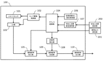
図1に本発明の第1の実施例の撮像装置の構成図を示す。 FIG. 1 shows a configuration diagram of an image pickup apparatus according to the first embodiment of the present invention.
撮像装置100は、イメージセンサ101を含む撮像系を有し、センサ駆動制御部102(センサ読出し制御手段)およびAD部103、アドレス変換部104によって撮像処理を行う。不図示のレンズを通った光束は、撮像装置100のイメージセンサ101に結像する。センサ駆動制御部102は、イメージセンサ101の蓄積動作や読み出し動作の制御を行う。センサ駆動制御部102によってイメージセンサ101の撮像処理を行うと、イメージセンサ101からは撮像信号がAD部103に出力され、AD部103にてAD変換される。アドレス変換部(読出し領域設定手段)104は、センサ駆動制御部102がイメージセンサ101を蓄積制御と読み出し制御を行う対象画素となるアドレスを算出する。イメージセンサ101からの間引き読み出しを行う場合は、イメージセンサ101の全画素のうち、読み出しを行う画素を対象画素としてアドレス出力し、読み出し対象とならないアドレスはスキップする。画像信号加工部105は、AD部103からの撮像信号データと、アドレス変換部104からの信号を入力し、撮像信号データに対し、フレーム同期信号や垂直同期信号、水平同期信号などを付与する。切出し領域設定部(関心領域設定入力手段)200は、撮像装置100の外部から、イメージセンサの撮像領域内で必要な画像データ(物体画像)を含む領域(以後、「関心領域」と記載する)の座標データを入力し設定する。外部とは、例えばPCなどから通信手段を用いて設定を行い、切出し位置設定部200に切り出し位置を設定する。切出し位置設定保持部107は、切出し位置設定部200で入力された設定データを保持する。全画素読出し設定保持部106は、イメージセンサ101の全画素を蓄積、読み出しするための範囲設定値を保持している。
The
アドレス変換部104は切出し位置設定保持部107と全画素読出し設定保持部106からの設定データを入力し、いずれかの設定データを選択し、センサ駆動制御部102と画像信号加工部105へ渡す。また、枠信号発生部108(境界識別手段)へ切出し位置設定保持部107の設定データを渡す。枠信号発生部108は、アドレス変換部104からの信号に基づき、切出し位置設定部200にて設定した関心領域を縁取る縁取り線を表示し、出力される画像内での関心領域の境界を明確に識別するための枠信号を生成する。
The
画像出力設定部201は、撮像装置100の外部から、関心領域を縁取り線と共に表示するか否かの設定及び、関心領域外の画素データを除外して出力するか、又は全画素のデータを出力するかの設定を行う。外部とは、例えばPCなどから通信手段を用いて設定を行い、枠信号発生部108に関心領域を示す枠表示の設定をする。
The image output setting
画像信号合成部109は、画像信号加工部105から出力される撮像信号データと枠信号発生部108の関心領域を表示するための枠信号を画像出力設定部201からの設定値に応じて画像を合成する。画像信号出力部110は、画像信号合成部109で生成された出力画像信号を撮像装置100の外部へ出力する。
The image
画像信号加工部105と画像信号合成部109で出力信号生成手段を構成し、イメージセンサ101から読み出された画素データ、及び、読出し領域、関心領域、上記の各種同期信号等の情報に基づき、撮像装置100の外部へ出力する出力画像信号を生成する。
The image
図2に、CMOSセンサ等、センサの一部領域の画素データのみを読み出すことが可能なイメージセンサ101の構造を示す。図2のImgは、撮像素子の画素エリアを示している。図2中の11から33までは、Imgに構成される画素配列の一部を示している。Img中の各画素は、V1、V2、V3、・・・およびH1、H2、H3、・・・の信号ラインを介して、垂直回路1011および水平回路1012にそれぞれ接続されている。垂直回路1011へは、Img中の各ラインの蓄積開始対象および蓄積終了対象を選択するためのVstselおよびVendsel、蓄積開始および終了のトリガを与えるためのVstおよびVendの信号ラインが接続されている。VstselおよびVendselから、トリガを入力されると、イメージセンサ101の参照するライン(V1、V2、V3、・・・)を垂直方向にインクリメントする。また、同様にして、水平回路1012には、Vendselで選択されたラインの水平方向の画素を選択するためのHselと、読み出しパルスを与えるためのHplsの信号ラインが接続されている。HselやHplsもVstselやVendselと同様に、トリガが与えられると、Vstselで選択中の垂直ライン中の参照画素を水平方向にインクリメントする。これらの信号ライン、Vstsel、Vendsel、Vst、Vend、Hsel、Hpls、を介して、図1のセンサ駆動制御部102から制御信号が入力される。Hplsに読み出し制御のためのパルスが入力されると、図2のアンプ1013を通じて、信号ラインoutから撮像信号がアナログ出力される。この撮像信号は、図1のAD部103に入力される。AD部103は、Hplsに同期して、AD部103に入力された撮像信号をAD変換する。センサ駆動制御部102で上記各制御信号を制御することで、イメージセンサ101の一部領域のみから画素データを読み出すことが可能となる。
FIG. 2 shows a structure of an
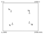
図3は、本発明の撮像装置100を用いて、撮影対象物Ta、Tb、Tc、Tdを撮影している構図を示している。図3の点線部分は、撮像装置100の画角を示している。このときの撮影映像を図4に示す。本実施例では、図3および図4で示す撮影映像において、撮影対象物Ta、Tb、Tc、Tdを含めた4つの周辺エリアを各関心領域として間引き読み出しを行う例について説明する。関心領域の数として4つの場合を例示するが、本発明は複数の関心領域を設定する場合に同様に適用できる。なお、本実施例では、撮影映像の画素数が横1000×縦1000を説明のために例示するが、本発明の撮影映像の画素数についてはこれに限定されない。以後、説明を容易にするため、撮影映像内の位置を直交XY座標(X、Y)で示し、図中、左右(水平)方向を右方向にX方向、上下(垂直)方向を下方向にY方向とする。本実施例では、撮影映像の左上の座標を(1,1)とし、右下の座標を(1000,1000)として説明する。
FIG. 3 shows a composition in which the imaging objects Ta, Tb, Tc, and Td are imaged using the
本実施例では、図5に示すように、Ta、Tb、Tc、Tdの4つの撮影対象物に対し、図1の切出し位置設定部200によって、4つの関心領域(ImgA、ImgB,ImgC、ImgD)が設定された場合の部分読み出し方法について説明する。
In this embodiment, as shown in FIG. 5, four regions of interest (ImgA, ImgB, ImgC, and ImgD) are obtained by the cut-out
関心領域ImgA、ImgB、ImgC、ImgDは、それぞれ撮影対象物Ta、Tb、Tc、Tdを含む領域であり、それぞれの領域の左上と右下の座標を与えることで、その座標を対角とする矩形の関心領域を定義する。図5では、関心領域ImgAは、左上(101,101)、右下(300,300)で囲まれた矩形領域である。関心領域ImgBは、左上(701,101)、右下(900,300)で囲まれた矩形領域である。関心領域ImgCは、左上(101,701)、右下(300,900)で囲まれた矩形領域である。関心領域ImgDは、左上(701,701)、右下(900,900)で囲まれた矩形領域である。図1の切出し位置設定部200は、不図示のコンピュータや設定手段などから設定しても良く、例えば、撮像装置に接続されたマウス、ジョイスティック、その他の入力手段を含む設定手段によって構成しても良い。
The regions of interest ImgA, ImgB, ImgC, and ImgD are regions that include the imaging objects Ta, Tb, Tc, and Td, respectively, and are given diagonal coordinates by giving the upper left and lower right coordinates of each region. Define a rectangular region of interest. In FIG. 5, the region of interest ImgA is a rectangular region surrounded by upper left (101, 101) and lower right (300, 300). The region of interest ImgB is a rectangular region surrounded by the upper left (701, 101) and the lower right (900, 300). The region of interest ImgC is a rectangular region surrounded by upper left (101,701) and lower right (300,900). The region of interest ImgD is a rectangular region surrounded by the upper left (701, 701) and the lower right (900, 900). The cut-out
本実施例では、図5のように設定された関心領域については部分読み出しを行い、関心領域以外の部分に関しては、読み飛ばしを行うことで、読み出し時間を減少させる。すなわち、イメージセンサにおいて、関心領域が存在しない部分を演算し、X座標値がどの関心領域のX座標の範囲にも含まれない領域とY座標値がどの関心領域のY座標の範囲にも含まれない領域を除外領域と定義して、画素情報を読み出す領域から除外することが可能となる。 In this embodiment, partial readout is performed for the region of interest set as shown in FIG. 5 and skipping is performed for portions other than the region of interest, thereby reducing the readout time. That is, in the image sensor, a region where the region of interest does not exist is calculated, and an X coordinate value is not included in the X coordinate range of any region of interest and a Y coordinate value is included in the Y coordinate range of any region of interest. It is possible to define an unexcluded area as an excluded area and exclude it from an area from which pixel information is read.
図1の切出し位置設定部200によって、図5に示すような関心領域ImgA、ImgB、ImgC、ImgDの座標がそれぞれ設定されると、切出し位置設定保持部107が、各関心領域の設定座標を保持する。アドレス変換部104は、切出し位置設定保持部107の設定値か、全画素読出し設定保持部106の設定値かを選択する。切出し位置設定部200による関心領域設定がない場合、アドレス変換部104では全画素読出し設定保持部106で保持されている設定値が選択され、全画素読出しモードとして動作する。また、切出し位置設定部200にて関心領域が設定されている場合、アドレス変換部104では切出し位置設定保持部107で保持されている設定値が選択され、部分読出しモードとして動作する。ここでは、図5に示したように、切出し位置設定部200によって、関心領域ImgAからImgDが設定されているため、アドレス変換部104は切出し位置設定保持部107での設定値を選択する。
When the coordinates of the regions of interest ImgA, ImgB, ImgC, and ImgD as shown in FIG. 5 are set by the cutout
次に、アドレス変換部104は、イメージセンサ101の蓄積および読み出しを行うためのアドレス情報であるラインや画素ナンバーをセンサ駆動制御部102に対して発行する。アドレス変換部104は、関心領域ImgAからImgDの全座標から、すべての画素位置(水平方向位置Hn)において関心領域を含まないライン(Vn)、及び、全てのライン(Vn)において関心領域を含まない水平方向画素位置(Hn)を求める。すなわち、図5より、次のように算出できる。全画面(1000,1000)において、垂直方向で間引き可能なライン(垂直方向位置)は、ラインV1からV100、ラインV301からV700、ラインV901からV1000である。さらに、水平方向で間引き可能な画素(水平方向位置)は、1画素目から100画素目、301画素目から700画素目、901画素目から1000画素目である。これらのラインおよび水平方向の画素(アドレス)は間引いて読み出すこととする。
Next, the
図2のアドレス変換部104が行うアドレス発行処理は、センサ駆動制御部102のイメージセンサ101に対するライン制御と同期して行われる。センサ駆動制御部102によるライン制御が完了すると、次のラインを制御するためのアドレス情報を更新して出力する。
The address issuing process performed by the
図6のフローチャートを参照してアドレス変換部104の動作を詳細に説明する。
ステップS601にて切出し位置設定部200から関心領域となる領域の座標データを入力し、切出し位置設定保持部107に記憶する。ステップS602では関心領域の設定がすべて終了したかを判断し、終了した場合はステップS603へ移行する。関心領域の設定が終了していない場合はステップS601へ戻り、関心領域の設定を繰り返す。
The operation of the
In step S <b> 601, coordinate data of a region to be a region of interest is input from the cutout
ステップS603では画像出力設定部201から指定される枠信号を表示するか否かと撮像装置の出力画素数を読み込む。ステップS604ではステップS603で読み込んだ撮影装置の設定出力画素数を判断し、全画素出力設定時はステップS605へ移行する。出力画素数が全画素で無い場合はステップS606へ移行する。ステップS605では全画素読出し用のアドレスをセンサ駆動制御部102と画像信号加工部105へも送出し、ステップS607へ移行する。ステップS606では切出し位置設定保持部107に保持されている切出し位置情報に対応するアドレスをセンサ駆動制御部102と画像信号加工部105へも送出し、ステップS608へ移行する。
In step S603, whether or not to display the frame signal designated from the image
ステップS607では切出し位置設定保持部107に切出し位置情報が保持されているか否かを判定し、切出し位置情報が保持されている場合はステップS608へ移行し、保持されていない場合はステップS610へ移行する。ステップS608では画像出力設定部201から指定された枠信号の表示状態を判定し、表示する場合はステップS609へ移行し、表示しない場合はステップS610へ移行する。
In step S607, it is determined whether or not the cutting position information is held in the cutting position setting holding
ステップS609では画像信号加工部105からの画像出力データに枠信号発生部108からの枠信号を画像信号合成部109にて重畳し、ステップS610へ送出する。
In step S609, the frame signal from the frame
ステップS610では画像信号合成部109で生成された出力画像信号を撮像装置100の外部へ出力する。
In step S610, the output image signal generated by the image
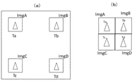
このような撮像装置100で得られる画像出力データの例を示す。まず、図7(a)は全画素出力で、枠表示無し設定での画像出力イメージであり、マシンビジョンカメラの初期の状態を示す。図7(a)の画像出力データを確認し、検査対象ImgA〜ImgDを撮像している4つの画素領域を切り出し位置設定部200で関心領域として設定し、読み出された関心領域のみ信号を画像化したものが図7(b)となる。図7(b)では各検査対象ImgA〜ImgDが捉えられているが、撮像画面のどの部分を切り出したか判別ができない状態であり、また、4つの関心領域の境界が判断できない状態となっている。これに対し図8(a)は、ステップS604で全画素出力と判断し、ステップS608で枠表示有りと判断した状態での画像出力イメージである。この表示状態はマシンビジョンカメラが撮像している全体の画面のどこを切り出しているかを確認するのに好適で、例えば検査対象が切出し位置以外の場所にいる場合、検査対象を関心領域に取り込むように関心領域を変更する際に効果を発揮する。
An example of image output data obtained by such an
また、図8(b)はステップS604で部分切出し出力と判断し、ステップS608で枠表示有りと判断した状態での画像出力イメージである。この表示状態は切出し画像の状態で各関心領域の境界が明確になるので検査対象外の異物が撮像された時にどこの切り出し位置に異物がいるか判断を付ける際に有効である。 FIG. 8B shows an image output image in a state in which it is determined in step S604 that partial cutout is output and in step S608 it is determined that frame display is present. Since this display state is a cut-out image state and the boundary between the regions of interest becomes clear, it is effective in determining where the foreign object is located when a foreign object that is not the subject of inspection is imaged.
上記の例で説明した関心領域は、それぞれの領域が、ライン方向(縦方向)、及びライン内の画素方向(横方向)で端部が一致している場合を示した。すなわち、4つの関心領域が、縦横で2×2の整然とした行列として配列している場合である。関心領域の大きさが互いに異なる場合や、縦方向又は横方向で互いの端部の位置が一致していない場合の例を図9に示す。このような場合は、部分読出しが設定されると、どの関心領域にも含まれないライン(縦方向位置)(図10(a)中のA,B,C)、画素位置(横方向位置)(図10(a)中のD,E,F)は読み飛ばされる。そして、関心領域の枠表示が設定されていない場合は、図10(b)のような画像が出力される。この場合においても、関心領域の枠表示を設定することによって、図10(c)のような画像が出力され、各関心領域の境界が明確にされ、撮影対象物(Ta,Tb,Tc,Td)の関心領域内での有無、位置を把握することができる。また、このような部分読出しにより、簡易な構成により出力データ量を減少させ、早いフレームレートでの画像出力に対応可能とすることができる。 The region of interest described in the above example shows a case where the end portions of the respective regions coincide with each other in the line direction (vertical direction) and the pixel direction in the line (horizontal direction). That is, the four regions of interest are arranged as a 2 × 2 orderly matrix in length and width. FIG. 9 shows an example in which the sizes of the regions of interest are different from each other, or the positions of the end portions of the regions of interest are not the same in the vertical direction or the horizontal direction. In such a case, when partial reading is set, lines (vertical direction positions) that are not included in any region of interest (A, B, C in FIG. 10A), pixel positions (horizontal position) (D, E, and F in FIG. 10A) are skipped. If the frame display of the region of interest is not set, an image as shown in FIG. 10B is output. Even in this case, by setting the frame display of the region of interest, an image as shown in FIG. 10C is output, the boundary of each region of interest is clarified, and the object to be imaged (Ta, Tb, Tc, Td) ) In the region of interest. In addition, by such partial reading, it is possible to reduce the output data amount with a simple configuration and to support image output at a high frame rate.
本実施例では、切出し位置設定部200、画像出力設定部201はPC等外部から時設定情報を受ける機能を有するものとし、説明したが、撮像装置100本体で設定しても構わない。
In the present embodiment, the cut-out
以上、複数の関心領域の設定時に本発明を適用することにより、全画素に対する各関心領域の設定状況を素早く把握することが出来、撮影前の画角合わせが容易に行える。 As described above, by applying the present invention at the time of setting a plurality of regions of interest, it is possible to quickly grasp the setting status of each region of interest for all pixels, and to easily adjust the angle of view before photographing.
図11に本発明の第2の実施例の撮像装置の構成図を示す。本実施例の特徴は、関心領域以外の画素データの階調を落とすことで、関心領域の表示を識別可能とすることにある。なお、実施例1と同一部分の説明は省略する。 FIG. 11 shows a configuration diagram of an image pickup apparatus according to the second embodiment of the present invention. The feature of this embodiment is that the display of the region of interest can be identified by reducing the gradation of the pixel data other than the region of interest. In addition, description of the same part as Example 1 is abbreviate | omitted.
図11において、切出し位置設定部200及び画像出力設定部201を介して得た切出し領域設定情報、枠表示設定情報、全画素表示設定情報を階調変更信号発生部111で受け取る。そして、関心領域に含まれる画素か否かの識別フラグを生成し、画素データ階調変換部112へ出力する。画素データ階調変換部112では関心領域内の画素についてはイメージセンサから読出した階調のまま画像信号出力部110を介し外部へ出力する。関心領域外の画素についてはAD部103のデータの下位ビットを遮断する(下位ビットを0又は1でマスクする)等の処理を行い、階調を落として出力する(図12)。
In FIG. 11, the gradation change signal generation unit 111 receives cutout region setting information, frame display setting information, and all pixel display setting information obtained through the cutout
実施例2のアドレス変換部での処理のフローチャートは図6に示した実施例1のフローチャートと同様であり、階調低減処理をステップS609の画像合成処理にて行うことが異なる。 The flowchart of the processing in the address conversion unit of the second embodiment is the same as the flowchart of the first embodiment shown in FIG. 6, except that the gradation reduction processing is performed in the image composition processing in step S609.
この構成をとることにより、枠表示を階調低減表示で代替できるので、枠表示で撮像画素のデータを上書きせずに、関心領域の判別をすることが可能となる。 By adopting this configuration, the frame display can be replaced by the gradation reduction display, and therefore it becomes possible to determine the region of interest without overwriting the data of the imaging pixels in the frame display.
図13に本発明の第3の実施例の撮像装置の構成図を示す。本実施例の特徴は、画素の間引き機能が機能した場合、全画素表示での枠表示は設定された機能に従って行うことにある。 FIG. 13 is a configuration diagram of an image pickup apparatus according to the third embodiment of the present invention. The feature of this embodiment is that when the pixel thinning function is activated, the frame display in the all pixel display is performed according to the set function.
画素の間引き機能の設定は例えば、1画素飛ばし、2画素飛ばし等、切出し設定された領域内の画素を全画素読み出さない設定をおこなう。このような画素情報の間引き設定は、外部のPC等から設定値が与えられる画像間引き設定部203(画像出力設定手段)から画像間引き処理部113(画素間引き処理手段)に与えられ、イメージセンサ101から読み出された画素データに対し間引き処理を行う。画素信号合成部109は、間引かれた画素信号に基づいて画像信号を生成する。
For the setting of the pixel thinning function, for example, one pixel skipping, two pixel skipping, or the like is performed such that all pixels in the cut-out region are not read out. Such pixel information decimation setting is given from the image decimation setting unit 203 (image output setting means) to which the setting value is given from an external PC or the like to the image decimation processing unit 113 (pixel decimation processing means), and the
この構成で実施例1と同等の枠表示させた際、全画素表示のときは、設定された関心領域以外の画素も設定された画素間引き状態で画像信号を生成され、間引かれた画素信号に対応する枠信号を重畳して形成された画像信号が出力される。 When a frame equivalent to that of the first embodiment is displayed in this configuration, when all pixels are displayed, an image signal is generated in a pixel thinning state in which pixels other than the set region of interest are set, and the thinned pixel signal is displayed. An image signal formed by superimposing the frame signal corresponding to is output.
このような構成をとることにより、出力される画像信号の信号量を低減させて、フレームレートを上げることが可能な、関心領域の位置が出力画像内で識別可能な画像信号を出力することができる。 By adopting such a configuration, it is possible to output an image signal in which the position of the region of interest can be identified in the output image, which can increase the frame rate by reducing the signal amount of the output image signal. it can.
100 撮像装置
101 イメージセンサ
102 センサ駆動制御部(センサ読出し制御手段)
104 アドレス変換部(読出し領域設定手段)
105 画像信号加工部(出力信号生成手段)
108 枠信号発生部(境界識別手段)
109 画像信号合成部(出力信号生成手段)
200 切出し位置設定部(関心領域設定入力手段)
DESCRIPTION OF
104 Address converter (reading area setting means)
105 Image signal processing unit (output signal generating means)
108 Frame signal generator (boundary identification means)
109 Image signal synthesis unit (output signal generation means)
200 Cutout position setting unit (region of interest setting input means)
Claims (8)
前記イメージセンサから画像信号を読み出す読出し領域を設定する読出し領域設定手段と、
前記イメージセンサからの前記読出し領域の画素信号の読出しを制御するセンサ読出し制御手段と、
前記センサ読出し制御手段によって読み出された画素信号に基づき、出力する画像信号を生成する出力信号生成手段と、
出力する画像信号で形成される画像において、関心領域の境界を識別可能とするための境界識別手段と、
を有し、
前記境界識別手段は、関心領域の縁取り線の画像信号を生成する枠信号発生手段であり、
前記出力信号生成手段は、前記センサ読出し制御手段によって読み出された画素信号に、該枠信号発生手段からの縁取り線の画像信号を重畳して、出力する画像信号を生成する、
ことを特徴とする撮像装置。 Region-of-interest setting input means for inputting a signal for setting a plurality of regions of interest in the imaging region of the image sensor;
Read area setting means for setting a read area for reading an image signal from the image sensor;
Sensor readout control means for controlling readout of pixel signals in the readout area from the image sensor;
Output signal generation means for generating an image signal to be output based on the pixel signal read by the sensor read control means;
Boundary identification means for enabling identification of a boundary of a region of interest in an image formed by an output image signal;
I have a,
The boundary identifying means is a frame signal generating means for generating an image signal of a border line of a region of interest,
The output signal generation unit generates an image signal to be output by superimposing a border line image signal from the frame signal generation unit on the pixel signal read by the sensor read control unit .
An imaging apparatus characterized by that.
前記イメージセンサの撮像領域内に関心領域を設定する設定手段と、 Setting means for setting a region of interest within the imaging region of the image sensor;
前記イメージセンサから前記関心領域の画像信号を部分的に読み出す第1モードと、前記イメージセンサから前記撮像領域の画像信号を全て読み出す第2モードのいずれかに従って画像信号を読み出す読出し手段と、 Reading means for reading out the image signal according to any one of a first mode for partially reading the image signal of the region of interest from the image sensor and a second mode for reading all the image signals of the imaging region from the image sensor;
前記読出し手段によって読み出された画像信号に基づいて画像を出力する出力手段と、を備え、 Output means for outputting an image based on the image signal read by the reading means,
前記出力手段は、前記設定手段によって前記関心領域が設定された後、前記読出し手段が前記第2モードに従って読み出した画像信号に基づいて画像を出力する場合、前記関心領域の境界を識別可能とするための縁取り線を前記画像に重畳して出力することを特徴とする撮像装置。 When the region of interest is set by the setting unit and the output unit outputs an image based on the image signal read in accordance with the second mode, the output unit can identify the boundary of the region of interest. An image pickup apparatus that outputs a border line for superimposing on the image.
Priority Applications (3)
| Application Number | Priority Date | Filing Date | Title |
|---|---|---|---|
| JP2013088026A JP6141084B2 (en) | 2013-04-19 | 2013-04-19 | Imaging device |
| US14/256,160 US9811751B2 (en) | 2013-04-19 | 2014-04-18 | Image pickup apparatus with boundary identifier for areas of interest |
| CN201410160302.5A CN104113710B (en) | 2013-04-19 | 2014-04-21 | Picture pick-up device and camera system |
Applications Claiming Priority (1)
| Application Number | Priority Date | Filing Date | Title |
|---|---|---|---|
| JP2013088026A JP6141084B2 (en) | 2013-04-19 | 2013-04-19 | Imaging device |
Publications (2)
| Publication Number | Publication Date |
|---|---|
| JP2014212462A JP2014212462A (en) | 2014-11-13 |
| JP6141084B2 true JP6141084B2 (en) | 2017-06-07 |
Family
ID=51710330
Family Applications (1)
| Application Number | Title | Priority Date | Filing Date |
|---|---|---|---|
| JP2013088026A Active JP6141084B2 (en) | 2013-04-19 | 2013-04-19 | Imaging device |
Country Status (3)
| Country | Link |
|---|---|
| US (1) | US9811751B2 (en) |
| JP (1) | JP6141084B2 (en) |
| CN (1) | CN104113710B (en) |
Families Citing this family (9)
| Publication number | Priority date | Publication date | Assignee | Title |
|---|---|---|---|---|
| US20140313381A1 (en) * | 2013-04-19 | 2014-10-23 | Canon Kabushiki Kaisha | Image pickup apparatus |
| JP2017195584A (en) * | 2016-04-22 | 2017-10-26 | キヤノン株式会社 | Imaging apparatus |
| KR102526559B1 (en) * | 2016-09-16 | 2023-04-27 | 소니 세미컨덕터 솔루션즈 가부시키가이샤 | Image pickup device and electronic apparatus |
| CN110933461B (en) * | 2018-09-19 | 2022-12-30 | 中兴通讯股份有限公司 | Image processing method, device, system, network equipment, terminal and storage medium |
| CN109831632B (en) * | 2019-01-21 | 2021-08-10 | 思特威(上海)电子科技股份有限公司 | Imaging method of image sensor |
| CN110012246B (en) * | 2019-03-26 | 2020-06-02 | 电子科技大学 | Method for realizing high-speed window function of focal plane array reading circuit |
| KR20210000985A (en) * | 2019-06-26 | 2021-01-06 | 삼성전자주식회사 | Vision sensor, image processing device comprising thereof and operating method of vision sensor |
| CN110536083B (en) * | 2019-08-30 | 2020-11-06 | 上海芯仑光电科技有限公司 | Image sensor and image acquisition system |
| KR20210100853A (en) | 2020-02-07 | 2021-08-18 | 삼성전자주식회사 | Electronic device and method for saving image |
Family Cites Families (8)
| Publication number | Priority date | Publication date | Assignee | Title |
|---|---|---|---|---|
| JPH09214836A (en) * | 1996-02-07 | 1997-08-15 | Olympus Optical Co Ltd | Image pickup device |
| US20020085219A1 (en) * | 2000-08-11 | 2002-07-04 | Victor Ramamoorthy | Method of and system for generating and viewing multi-dimensional images |
| JP4416753B2 (en) | 2006-03-31 | 2010-02-17 | キヤノン株式会社 | Solid-state imaging device |
| JP4367963B2 (en) | 2007-10-24 | 2009-11-18 | キヤノン株式会社 | Imaging apparatus, imaging system, and driving method of imaging apparatus |
| JP5142825B2 (en) * | 2008-05-28 | 2013-02-13 | キヤノン株式会社 | Image display device and image display method |
| IL204089A (en) * | 2010-02-21 | 2014-06-30 | Elbit Systems Ltd | Method and system for detection and tracking employing multi-view multi-spectral imaging |
| JP5907738B2 (en) | 2012-01-23 | 2016-04-26 | オリンパス株式会社 | Imaging apparatus, display method, and program |
| RU2012119843A (en) * | 2012-05-15 | 2013-11-20 | Общество с ограниченной ответственностью "Синезис" | METHOD FOR DISPLAYING VIDEO DATA ON A MOBILE DEVICE |
-
2013
- 2013-04-19 JP JP2013088026A patent/JP6141084B2/en active Active
-
2014
- 2014-04-18 US US14/256,160 patent/US9811751B2/en active Active
- 2014-04-21 CN CN201410160302.5A patent/CN104113710B/en active Active
Also Published As
| Publication number | Publication date |
|---|---|
| US9811751B2 (en) | 2017-11-07 |
| JP2014212462A (en) | 2014-11-13 |
| CN104113710A (en) | 2014-10-22 |
| US20140313320A1 (en) | 2014-10-23 |
| CN104113710B (en) | 2018-01-30 |
Similar Documents
| Publication | Publication Date | Title |
|---|---|---|
| JP6141084B2 (en) | Imaging device | |
| JP6702323B2 (en) | Camera module, solid-state imaging device, electronic device, and imaging method | |
| JP5794705B2 (en) | Imaging apparatus, control method thereof, and program | |
| US8036482B2 (en) | Image processing apparatus and method, program, and recording medium | |
| US10645258B2 (en) | Multi-camera system, method of controlling a multi-camera system, and camera | |
| JP2007288731A (en) | Real-time panoramic image composing method and apparatus therefor | |
| JP2012028949A (en) | Image processing device and control method of the same | |
| JP5141470B2 (en) | Image composition method and image processing system | |
| KR20130140389A (en) | Apparatus and method for providing image | |
| JP6104066B2 (en) | Image processing apparatus and image processing method | |
| JP6162971B2 (en) | Image processing apparatus, image processing method, imaging apparatus, and control method thereof | |
| JP6565326B2 (en) | Imaging display device and control method thereof | |
| US20140313381A1 (en) | Image pickup apparatus | |
| JP2009065519A (en) | Image processing apparatus | |
| JP2011253381A (en) | Target tracking device and target tracking method | |
| JP2010200360A (en) | Imaging apparatus, stroboscopic image generation method, and program | |
| CN110692235B (en) | Image processing apparatus, image processing program, and image processing method | |
| JP2006325073A (en) | Image inputting apparatus | |
| JP2010273261A (en) | Image processing apparatus and imaging apparatus | |
| JP2009027437A (en) | Image processor, image processing method and imaging device | |
| JP2012068761A (en) | Image processing device | |
| JP2014155086A (en) | Field angle adjustment device and field angle adjustment method | |
| JP5110713B2 (en) | Multi-lens photographing apparatus, through image display method and program | |
| JP2007299219A (en) | Method of calibrating distortion in photography image | |
| JP2016192755A (en) | Image signal processing device, image signal processing method and program |
Legal Events
| Date | Code | Title | Description |
|---|---|---|---|
| A621 | Written request for application examination |
Free format text: JAPANESE INTERMEDIATE CODE: A621 Effective date: 20160317 |
|
| A977 | Report on retrieval |
Free format text: JAPANESE INTERMEDIATE CODE: A971007 Effective date: 20161205 |
|
| A131 | Notification of reasons for refusal |
Free format text: JAPANESE INTERMEDIATE CODE: A131 Effective date: 20170124 |
|
| A521 | Request for written amendment filed |
Free format text: JAPANESE INTERMEDIATE CODE: A523 Effective date: 20170321 |
|
| TRDD | Decision of grant or rejection written | ||
| A01 | Written decision to grant a patent or to grant a registration (utility model) |
Free format text: JAPANESE INTERMEDIATE CODE: A01 Effective date: 20170404 |
|
| A61 | First payment of annual fees (during grant procedure) |
Free format text: JAPANESE INTERMEDIATE CODE: A61 Effective date: 20170502 |
|
| R151 | Written notification of patent or utility model registration |
Ref document number: 6141084 Country of ref document: JP Free format text: JAPANESE INTERMEDIATE CODE: R151 |