JP6141083B2 - Site monitoring apparatus and method - Google Patents
Site monitoring apparatus and method Download PDFInfo
- Publication number
- JP6141083B2 JP6141083B2 JP2013087884A JP2013087884A JP6141083B2 JP 6141083 B2 JP6141083 B2 JP 6141083B2 JP 2013087884 A JP2013087884 A JP 2013087884A JP 2013087884 A JP2013087884 A JP 2013087884A JP 6141083 B2 JP6141083 B2 JP 6141083B2
- Authority
- JP
- Japan
- Prior art keywords
- image forming
- information
- forming apparatus
- monitoring system
- monitoring
- Prior art date
- Legal status (The legal status is an assumption and is not a legal conclusion. Google has not performed a legal analysis and makes no representation as to the accuracy of the status listed.)
- Expired - Fee Related
Links
Images


Landscapes
- Engineering & Computer Science (AREA)
- Theoretical Computer Science (AREA)
- General Physics & Mathematics (AREA)
- Physics & Mathematics (AREA)
- Business, Economics & Management (AREA)
- Tourism & Hospitality (AREA)
- Management, Administration, Business Operations System, And Electronic Commerce (AREA)
- Facsimiles In General (AREA)
- Computer And Data Communications (AREA)
- Accessory Devices And Overall Control Thereof (AREA)
- General Engineering & Computer Science (AREA)
- General Business, Economics & Management (AREA)
- Strategic Management (AREA)
- Primary Health Care (AREA)
- Marketing (AREA)
- Multimedia (AREA)
- Signal Processing (AREA)
- Human Computer Interaction (AREA)
- Human Resources & Organizations (AREA)
- General Health & Medical Sciences (AREA)
- Economics (AREA)
- Health & Medical Sciences (AREA)
Description
本発明は、複数システムが連携する際の管理手法に関するものである。 The present invention relates to a management method when a plurality of systems cooperate.
従来から、サーバーで印刷要求を行ったクライアントPCから印刷ログを収集し、集計を行う集計システムが存在する。また、ネットワーク機器を監視し、リモートサイトのシステムがメンテナンスに関わるサービス提供するリモートメンテナンスシステムも存在する。 2. Description of the Related Art Conventionally, there are aggregation systems that collect print logs from client PCs that have requested printing by a server and perform aggregation. There is also a remote maintenance system that monitors network devices and provides services related to maintenance by a remote site system.
また、従来のシステムにおいて、クライアントPC側で印刷ログを送信するタイミングに、サーバーが正常に稼働しているかを判定して、異常があった場合には送信すべき印刷ログを一時的にクライアントPC側に退避しておくといった技術も存在する(特許文献1参照)。 Further, in the conventional system, it is determined whether the server is operating normally at the timing when the print log is transmitted on the client PC side. If there is an abnormality, the print log to be transmitted is temporarily stored in the client PC. There is also a technique of retreating to the side (see Patent Document 1).
一方で、近年、オフィス向けのソリューションとして「マネージドプリントサービス(MPS)」が注目され、市場規模が拡大されている。MPSは、企業のオフィス出力環境の現状を分析したうえで、最適な出力環境を構築、その環境を継続的に維持、運用していくアウトソーシングサービスである。MPS事業を実現するためには、従来の様々なシステムのそれぞれで利用していたようなネットワーク機器の稼働情報やログ情報などを収集し、MPSの観点から分析することが必要となる。 On the other hand, in recent years, “Managed Print Service (MPS)” has attracted attention as a solution for offices, and the market scale has been expanded. MPS is an outsourcing service that analyzes the current state of a company's office output environment, constructs an optimum output environment, and continuously maintains and operates the environment. In order to realize the MPS business, it is necessary to collect network device operation information, log information, and the like used in each of various conventional systems and analyze them from the viewpoint of MPS.
MPS事業に迅速に対応するための1つの考え方として、従来のシステムと連携(もしくは統合)することが考えられる。ここで、システム連携の一つの問題として、運用フローの違いが挙げられる。 One way to quickly respond to the MPS business is to link (or integrate) with conventional systems. Here, one problem of system cooperation is the difference in operational flow.
それぞれのシステムは、従来から管理対象とするネットワーク機器や顧客を継続して管理する必要があるため、ここで想定しているMPSを目的とした分析システムとは、独立して動作する必要がある。そのため、各システムの管理対象のネットワーク機器の機器情報の登録処理や、管理内容に係る各種設定は、それぞれのシステムごとに依存する任意のタイミングで行われることになる。集計システムやメンテナンスシステム、分析システムなどのネットワーク機器を何らかの目的で管理する複数の管理システムのそれぞれに対して、各種設定を行う担当者は、多くの場合に異なる。 Since each system has conventionally been required to continuously manage network devices and customers to be managed, it is necessary to operate independently from the analysis system intended for MPS assumed here. . For this reason, the registration processing of the device information of the network device to be managed by each system and various settings related to the management contents are performed at an arbitrary timing depending on each system. The person in charge of making various settings for each of a plurality of management systems that manage network devices such as a totaling system, a maintenance system, and an analysis system for some purpose is often different.
そこで本発明は、これらの点を鑑みてなされたものであり、システム連携する際に、監視対象となる画像形成装置の稼働情報の管理について柔軟な運用を可能とすることを目的とする。 Accordingly, the present invention has been made in view of these points, and an object of the present invention is to enable flexible operation for management of operation information of an image forming apparatus to be monitored when the system is linked.
上記課題を解決するために、本発明の顧客環境に設置された拠点監視装置は、利用状況分析システムと、監視システムと、通信可能な拠点監視装置であって、
前記利用状況分析システム及び前記監視システムが提供する複数のサービスと、各サービスの対象となる画像形成装置とを対応づけたリストを前記利用状況分析システムから取得して、管理する管理手段と、前記管理されたリストに含まれる画像形成装置から該画像形成装置の稼働情報を含む情報を取得する取得手段と、前記取得手段により取得された情報を、前記リストに基づき、前記利用状況分析システム及び前記監視システムのいずれかに送信する送信手段と、前記リストに含まれる前記監視システムが提供するサービスの対象となる画像形成装置の中で、前記監視システムに未登録であることを示すフラグが有効な画像形成装置から取得された該画像形成装置の稼働情報を含む情報を、前記監視システムに送信することなく、前記拠点監視装置がアクセス可能なデータベースに保存する保存手段と、を有し、前記送信手段は、前記データベースの残りの容量が閾値を下回った際に、前記保存手段により保存された情報の一部を、前記利用状況分析システムに対して送信することを特徴とする。
In order to solve the above problems, the site monitoring device installed in the customer environment of the present invention is a usage status analysis system, a monitoring system, and a site monitoring device capable of communication ,
Wherein a plurality of service usage analysis system and that the monitoring system provides a list that associates the subject to the image forming apparatus of each service is obtained from the usage analysis system, and a management means for managing the obtaining means from the image forming apparatus included in the management list to obtain information including the operation information of the image forming apparatus, the information acquired by the acquisition unit, based on the list, the usage analysis system and the Among the transmission means for transmitting to one of the monitoring systems and the image forming apparatus that is the target of the service provided by the monitoring system included in the list, a flag indicating that the flag is not registered in the monitoring system is valid the information including the operation information of has been the image forming apparatus acquired from the image forming apparatus, without transmitting to the monitoring system, the bases Comprising a storage means for the monitoring device to store in a database accessible, wherein the transmitting means, when the remaining capacity of the database is below a threshold value, a part of the information stored by the storing means, It transmits to the said utilization condition analysis system, It is characterized by the above-mentioned.
本発明によれば、システム連携する際に、監視対象となる画像形成装置の稼働情報の管理について柔軟な運用が可能となる。 According to the present invention, it is possible to flexibly operate the management of the operation information of the image forming apparatus to be monitored when the system is linked.
以下、本発明を実施するための最良の形態について図面を用いて説明する。 The best mode for carrying out the present invention will be described below with reference to the drawings.
<実施例1>
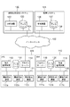
図1は、本実施例におけるネットワークシステムの全体構成を示すブロック図である。
<Example 1>
FIG. 1 is a block diagram showing the overall configuration of the network system in this embodiment.
図1に示すように、本ネットワークシステムは、利用状況分析システム(100)や監視システム(101)をはじめとする複数のシステムが接続されている。 As shown in FIG. 1, the network system is connected to a plurality of systems including a usage analysis system (100) and a monitoring system (101).
利用状況分析システム100で、顧客などの拠点ネットワークに存在する画像形成装置(112、117)の各種情報を収集・集計し、分析結果をレポート出力するサービスなどの提供を目的としたリモートシステムである。利用状況分析システム(100)には、分析装置(102)と、データベース(103)が含まれている。データベース(103)には、レポートに必要な画像形成装置の各種データ(カウンタ、ジョブ履歴、インシデント、障害履歴など)や、レポートテンプレート、画像形成装置のデータを収集するための情報などを蓄積している。分析装置(102)とデータベース(103)はLAN(104)で接続されており、LAN(104)はインターネット(105)に接続可能となっている。なお、データベース(103)は、物理的に分析装置(102)内に存在してもよい。さらに、分析装置(102)からアクセス可能であれば、インターネット(105)を経由した別の場所に存在しても構わない。
The usage
分析装置(102)は、後述する拠点監視装置(113、118)から、管理対象としての画像形成装置の識別情報やレポートに必要な各種情報などを収集、加工して、利用状況の分析結果を外部に提供する機能を有する。さらに、分析装置(102)は、管理装置(106)から、データベース(107)に格納された画像形成装置の稼働情報やカウンタ情報をWebServiceI/Fで収集し、収集したデータを集計して利用状況結果を外部に提供することも可能である。 The analysis apparatus (102) collects and processes identification information of the image forming apparatus as a management target and various kinds of information necessary for reports from the site monitoring apparatuses (113, 118) to be described later, and analyzes the analysis result of the usage situation. Has a function to be provided externally. Further, the analysis apparatus (102) collects the operation information and counter information of the image forming apparatus stored in the database (107) from the management apparatus (106) by using the WebService I / F, and totals the collected data and uses the information. It is also possible to provide the results externally.
分析装置(102)は、収集した情報をレポートとして出力する機能を有する。レポートに必要な情報としては、ジョブ履歴、カウンタ情報、稼働情報、インシデント情報などを例として挙げることができる。分析装置(102)は、インターネット(105)を介して接続したPCに対し、レポート機能の1つとして、データベース(103)で蓄積した情報、または加工した情報を閲覧するためのWEBページを提供している。このWEBページは、ユーザ認証により、権限別に閲覧内容を限定し提供している。さらにWEBページから一部データの変更も可能としている。 The analysis device (102) has a function of outputting the collected information as a report. Examples of information necessary for the report include job history, counter information, operation information, incident information, and the like. The analysis device (102) provides a WEB page for browsing information stored in the database (103) or processed information as one of the report functions to a PC connected via the Internet (105). ing. This WEB page provides limited browsing contents for each authority by user authentication. Furthermore, some data can be changed from the WEB page.
分析装置(102)は、WEBページ上で特定の権限を持つ担当者が、各種情報を顧客単位で登録する。登録する情報は、たとえば、利用状況分析システム(100)の管理対象となる画像形成装置、画像形成装置の情報を収集するための拠点監視装置(113、118)などがあげられる。担当者は、登録した画像形成装置と拠点監視装置(113、118)を機能単位で紐付することができる。後述する拠点監視装置(113、118)は、この紐付情報をもとに、画像形成装置(112、117)から各種情報を収集し、分析装置(102)、管理装置(106)などの外部システムに送信する。 In the analysis apparatus (102), a person in charge with specific authority on the WEB page registers various information in units of customers. Examples of the information to be registered include an image forming apparatus to be managed by the usage status analysis system (100), a base monitoring apparatus (113, 118) for collecting information on the image forming apparatus, and the like. The person in charge can associate the registered image forming apparatus and the site monitoring apparatus (113, 118) in units of functions. The site monitoring devices (113, 118), which will be described later, collect various information from the image forming devices (112, 117) based on the association information, and external systems such as an analysis device (102) and a management device (106). Send to.
監視システム101は、画像形成装置などのデバイスの情報を管理するリモートシステムである。とくに、顧客のネットワーク上の画像形成装置の稼働情報を収集し、消耗品発注や、故障修理などのメンテナンスに関わるサービス提供を目的としたシステムである。
The
監視システム(101)には、管理装置(106)と、データベース(107)が含まれる。データベース(107)は、顧客環境に設置された画像形成装置や拠点監視装置などのデバイスを監視するための機器を識別するための識別情報、監視スケジュール、保守のための保守会社の情報や顧客情報などを管理する。識別情報としては、装置のシリアル番号やモデル情報、デバイス名称、アドレス情報などといった情報が含まれる。また、顧客側から収集した画像形成装置のカウンタ情報、障害情報の履歴情報、障害パターンテーブルなどを蓄積している。管理装置(106)とデータベース(107)は、LAN(108)で接続されており、LAN(108)はインターネット(105)に接続可能となっている。なお、データベース(107)は、物理的に管理装置(106)内に存在してもよい。さらに、管理装置(106)からアクセス可能であれば、インターネット(105)を経由した別の場所に存在しても構わない。 The monitoring system (101) includes a management device (106) and a database (107). The database (107) includes identification information for identifying devices for monitoring devices such as image forming apparatuses and site monitoring apparatuses installed in the customer environment, monitoring schedule, maintenance company information for maintenance, and customer information. Manage etc. The identification information includes information such as the device serial number, model information, device name, and address information. Further, counter information of the image forming apparatus collected from the customer side, history information of failure information, failure pattern table, and the like are accumulated. The management device (106) and the database (107) are connected by a LAN (108), and the LAN (108) can be connected to the Internet (105). The database (107) may physically exist in the management apparatus (106). Furthermore, as long as it can be accessed from the management apparatus (106), it may exist in another place via the Internet (105).
管理装置(106)は、後述する拠点監視装置(113、118)から、監視対象としての画像形成装置の識別情報、カウンタ情報、稼働情報(障害情報を含む)を収集して、データベースに蓄積する。また、蓄積された稼働情報を必要に応じて加工し、警告等として外部に提供する機能を有する。また、管理装置(106)は、これらの蓄積している情報を、ネットワークを介して配信する機能を有する。 The management apparatus (106) collects identification information, counter information, and operation information (including failure information) of the image forming apparatus as a monitoring target from the site monitoring apparatuses (113, 118) described later, and stores them in the database. . In addition, it has a function of processing the accumulated operation information as necessary and providing it to the outside as a warning or the like. The management device (106) has a function of distributing the accumulated information via the network.
稼働情報としては、たとえば、トナー切れ、ドアオープン、ドラム交換、カートリッジなし、冷却ファン異常、基板異常、原稿台ガラス汚れ、ステイプル切れ、給紙センサ光量不足などを例として挙げることができる。また、フォントメモリオーバーフロー、レンダリングエラー、定着器異常、カウンタ異常、両面ユニット異常、紙詰まりなどをあげることもできる。 Examples of the operation information include toner out, door open, drum replacement, no cartridge, cooling fan abnormality, substrate abnormality, platen glass stains, stapling, and insufficient amount of paper feed sensor. In addition, font memory overflow, rendering error, fixing device abnormality, counter abnormality, duplex unit abnormality, paper jam, and the like can be given.
カウンタ情報としては、画像形成装置における出力枚数を示すカウンタや、画像形成装置内の部品の消耗度を示す部品カウンタなどとそれらの値が含まれる。より詳細には、出力枚数を示すカウンタの種類として、課金対象とすべき課金カウンタ、顧客の部門別に集計された部門カウンタ、用紙サイズ別に集計されたサイズ別カウンタ、などがあげられる。 The counter information includes a counter indicating the number of output sheets in the image forming apparatus, a component counter indicating the wear level of the components in the image forming apparatus, and their values. More specifically, the types of counters indicating the number of output sheets include a billing counter to be billed, a department counter counted for each customer department, a size counter counted for each paper size, and the like.
管理装置(106)は、監視対象の画像形成装置や、監視に関する設定をマージして一括管理できる。管理装置(106)は、インターネット(105)を介して接続したPCに対し、データベース(107)で蓄積した情報、または加工した情報を閲覧するWEBページを提供している。このWEBページは、ユーザ認証により、権限別に閲覧内容を限定し提供している。さらにWEBページから一部データの変更も可能としている。管理装置(106)は、監視システム(101)の監視対象となる画像形成装置を、WEBページ上、または、WebServiceI/Fを介して、特定の権限を持つ担当者が登録する。管理装置(106)は、顧客環境に設置された拠点監視装置や画像形成装置から、監視対象外の画像形成装置の稼働情報などを受信した場合には、データベース(107)には格納せず、破棄する。 The management apparatus (106) can collectively manage the image forming apparatuses to be monitored and the settings related to monitoring. The management apparatus (106) provides a WEB page for browsing information stored in the database (107) or processed information to a PC connected via the Internet (105). This WEB page provides limited browsing contents for each authority by user authentication. Furthermore, some data can be changed from the WEB page. In the management apparatus (106), the person in charge with specific authority registers the image forming apparatus to be monitored by the monitoring system (101) on the WEB page or via the WebService I / F. When the management device (106) receives operation information of an image forming apparatus that is not monitored from a site monitoring device or an image forming device installed in the customer environment, the management device (106) does not store it in the database (107). Discard.
次に、顧客側のシステム(109、110)の構成例について説明する。図1では複数の顧客が存在して、それぞれ異なるネットワーク環境を構築している例を示している。図1では、2つの顧客システム(109、110)が示されているが、2以上の顧客を想定しても、本発明は適用可能である。 Next, a configuration example of the customer side system (109, 110) will be described. FIG. 1 shows an example in which a plurality of customers exist and different network environments are constructed. In FIG. 1, two customer systems (109, 110) are shown, but the present invention is applicable even when two or more customers are assumed.
顧客システム(109)においては、インターネット(105)に接続されたLAN(111)に接続された画像形成装置(112a、112b、112c)が、拠点監視装置(113)により監視されている。拠点監視装置(113)は、プロキシサーバ(114)を介してインターネット(105)経由で分析装置(102)、管理装置(106)と通信している。 In the customer system (109), the image forming apparatuses (112a, 112b, 112c) connected to the LAN (111) connected to the Internet (105) are monitored by the site monitoring apparatus (113). The site monitoring device (113) communicates with the analysis device (102) and the management device (106) via the proxy server (114) via the Internet (105).
拠点監視装置(113)は、画像形成装置(112a、112b、112c)から収集したカウンタ情報や稼働情報などの情報、収集処理を行った日時や結果などをデータベース(115)に保存する。画像形成装置から自発的に通知されてきた障害情報なども、日時などとともに、データベース(115)に保存する。また、画像形成装置(112a、112b、112c)に配信すべき指示情報、画像形成装置(112a、112b、112c)から情報を取得するための各種設定情報もデータベース(115)内に保存する。このデータベース(115)は、LAN(111)上に接続されているが、拠点監視装置(113)の内部に独立して存在してもよい。さらに、このデータベース(115)は、拠点監視装置(113)からアクセス可能であれば、インターネット(105)を経由した別の場所に存在しても構わない。拠点監視装置(113)は、画像形成装置(112a、112b、112c)から受信した情報を、いったんデータベース(115)に保存し、管理装置(106)や分析装置(102)に送信する機能を有している。また、画像形成装置が直接、管理装置(106)などに稼働情報やカウンタ情報を送信する機能を有している場合もある。 The site monitoring apparatus (113) stores information such as counter information and operation information collected from the image forming apparatuses (112a, 112b, and 112c), the date and time of collection processing, the results, and the like in the database (115). Fault information and the like spontaneously notified from the image forming apparatus are also stored in the database (115) together with the date and time. Further, instruction information to be distributed to the image forming apparatuses (112a, 112b, 112c) and various setting information for acquiring information from the image forming apparatuses (112a, 112b, 112c) are also stored in the database (115). The database (115) is connected to the LAN (111), but may exist independently in the site monitoring device (113). Furthermore, this database (115) may exist in another place via the Internet (105) as long as it can be accessed from the site monitoring device (113). The site monitoring device (113) has a function of temporarily storing the information received from the image forming devices (112a, 112b, 112c) in the database (115) and transmitting the information to the management device (106) and the analysis device (102). doing. In some cases, the image forming apparatus has a function of transmitting operation information and counter information directly to the management apparatus (106).
拠点監視装置(113)は、分析装置(102)から管理対象となる画像形成装置と、実行すべき管理機能との紐付リストを受信し、紐付リストに基づき画像形成装置(112a、112b、112c)から各種情報を収集する。さらに、当該リストに基づき画像形成装置(112a、112b、112c)に対して、通信スケジュールや通知対象のデータの種類などの指示情報として配信し、設定させる。 The site monitoring device (113) receives from the analysis device (102) a linked list of image forming devices to be managed and management functions to be executed, and based on the linked list, the image forming devices (112a, 112b, 112c). Collect various information from Further, based on the list, the image forming apparatuses (112a, 112b, 112c) are distributed and set as instruction information such as a communication schedule and the type of data to be notified.
また、顧客システム(110)においても、顧客システム(109)と同様の処理が行われる。 In the customer system (110), the same processing as that of the customer system (109) is performed.
<情報処理装置のH/W構成を示す図>
図2は、拠点監視装置(113、118)、管理装置(106)、分析装置(102)などとして動作可能な情報処理装置の構成の一例を説明するブロック図である。図示しない、管理装置(106)や分析装置(102)などのバックエンドに設置される情報処理装置の構成にも相当させることができる。
<Figure showing H / W configuration of information processing apparatus>
FIG. 2 is a block diagram illustrating an example of the configuration of an information processing apparatus that can operate as a site monitoring apparatus (113, 118), a management apparatus (106), an analysis apparatus (102), and the like. A configuration of an information processing apparatus installed in the back end such as a management apparatus (106) or an analysis apparatus (102) (not shown) can also be used.
図2において、201は情報処理装置の制御手段であるCPUであり、ハードディスク(HD)(205)に格納されているアプリケーションプログラム、プリンタドライバプログラム、OSや本発明の機器管理プログラムなど実行する。また、本構成例ではCPUを1つとしたが、複数の場合もあり得る。
In FIG. 2,
202は書き換え不能な記憶手段であるROMであり、内部には基本I/Oプログラム、本装置上の各処理を司るプログラム、データを記憶する。
RAM(203)にはプログラムの実行に必要な情報、ファイル等を一時的に格納する制御を行い、CPU(201)の主メモリ、ワークエリア等として機能する。なお、後述する各フローチャートにおける拠点監視装置(113、118)と分析装置(102)、管理装置(106)の各ステップの処理は、CPU(201)が、204、205等の記憶手段に格納されたプログラムコードに基づく処理を実行することによって、実現されるものとする。 The RAM (203) performs control for temporarily storing information, files, and the like necessary for program execution, and functions as a main memory, work area, and the like of the CPU (201). The processing of each step of the site monitoring device (113, 118), analysis device (102), and management device (106) in each flowchart to be described later is stored in storage means such as 204, 205 by the CPU (201). It is realized by executing processing based on the program code.
204は外部機器I/Fであり、外部記憶装置等を接続する。外部記憶装置を接続することにより、記憶媒体に記憶されたプログラム等を本情報処理装置にロードすることができる。なお、記憶媒体は、FD、CD−ROM、CD−R、CD−RW、PCカード、DVD、ICメモリカード、MO、メモリスティック等、任意である。
An external device I /
205はハードディスク(HD)であり、本装置の各処理にかかわるプログラムやデータ、一時的なデータ、本発明に関わる監視対象の画像形成装置(112、117)に関する情報、および画像形成装置(112、117)から収集したデータ、レポートテンプレート、レポートデータ等の各種データを記憶する。また、本構成ではHDを1つとしたが、複数の場合もありえる。 A hard disk (HD) 205 is a program and data related to each process of the apparatus, temporary data, information on the image forming apparatuses (112, 117) to be monitored according to the present invention, and an image forming apparatus (112, 112). 117), various data such as data collected from 117), report template, report data, etc. are stored. In this configuration, one HD is used, but there may be a plurality of HDs.
206は指示入力手段である入力装置であり、キーボードやポインティングデバイスである。本システムのユーザが情報処理装置に対して、設定、操作等の入力指示を行う。207は表示手段であるディスプレイであり、入力装置(206)から入力した指示や、管理対象の画像形成装置(112、117)の状態や設定を表示するものである。なお、実際にはアプリケーションがOSの仕組みを介して発行した描画コマンドを、グラフィカルカードが解釈し、アナログ信号、あるいはデジタル信号に変換した情報が表示手段に表示される場合等がある。本実施形態における表示制御とは、表示手段に表示させるべくOSを介して、描画コマンドの発生を行わせる処理を含むものとする。
208はネットワークI/Fであり、ネットワーク経由でLANおよびインターネットに接続し、外部と情報交換を行う。該インターフェース(209)を介して情報処理装置は外部装置とのデータのやり取りを行う。209はシステムバスであり、情報処理装置内のこれら要素(201〜208)のデータの流れを司るものである。
<画像形成装置のH/W構成を示す図>
図3は、本実施形態における画像形成装置(112、117)のプリンタ制御部とその周辺部分のブロック構成図である。
<Figure showing H / W configuration of image forming apparatus>
FIG. 3 is a block diagram of the printer control unit and its peripheral part of the image forming apparatus (112, 117) in this embodiment.
301はプリンタコントローラーであり、印刷などをリクエストするホストコンピュータなどの外部ネットワークと、各種データの送受信を所定のプロトコルで実行するためのネットワークI/F(316)をもつ。さらに、通信と画像データの受信、および受信した画像データをプリンタが印字可能な情報に展開するとともに、後述のプリンタエンジン制御部(302)との間で信号のやり取りおよびシリアル通信を行うためのビデオI/F(317)等を備える。また、ネットワークI/F(316)は、拠点監視装置(113、118)、分析装置(102)、管理装置(106)等との通信制御を行う。
A
312はCPUで、ROM(314)あるいはHD(外部メモリ)(319)に記憶された制御プログラムなどに基づいて、システムバス(323)に接続されている各種デバイスとのアクセスを統括的に制御する。さらに、ビデオI/F(317)を介して接続されるプリンタエンジンに出力情報としての画像信号を出力する。313はRAMで、CPU(312)の主メモリ、ワークエリア等として機能する。315はメモリコントローラ(DKC)で、ブートプログラム、種々のアプリケーション、フォントデータ、ユーザファイル、設定ファイル等を記憶するハードディスク(HD)等の外部記憶媒体(319)とのアクセスを制御する。
320は操作部で、表示部(321)やキーボード等の入力手段を含んでおり、入出力I/F(318)を介してオペレータへの情報提供や、オペレータからの入力指示を行わせるものである。
An
302はエンジン制御部であり、プリンタコントローラー(301)との間の信号のやり取りや、シリアル通信を介してプリンタエンジンの各ユニットの制御を行う。
An
303は用紙搬送制御部で、プリントする用紙を給紙搬送し、プリント後の排紙までの紙搬送をエンジン制御部(302)の指示に基づき実行する。304は光学系制御部で、スキャナモーターの駆動およびレーザのON/OFF制御をエンジン制御部(302)の指示に基づき実行する。305は高圧系制御部で、帯電、現像、転写などの電子写真プロセスに必要な高圧出力をエンジン制御部(302)の指示に基づき実行する。306は定着機温度制御部で、エンジン制御部(302)の指示に基づき定着器の温度制御を行うとともに、定着器の異常検出等を行う。
A sheet
307はジャム検出部で、用紙搬送中の搬送不良を検出する。308は故障検出部で、プリンタ内の機能部の故障を検出する。309は印刷完了検知部で、印刷が正常に行われたことを検出して、エンジン制御部(302)に通知する。310はカウンタ制御部で、印刷などの処理が行われた際に、各種カウンタ情報を更新する。
エンジン制御部(302)には、プリンタエンジンの制御に必要な情報またはエンジンや各ユニットの情報を管理する管理部(311)がある。管理部(311)では、後述する機器情報取得部(504)などに情報提供する。これにより、外部ネットワーク上の装置からの要求に応じて、例えば、カウンタ制御部(310)からカウンタ情報を取得し、ビデオI/F(317)及び、ネットワークI/F(316)を介して外部ネットワーク上の装置に送信される。その他、外部ネットワーク上の装置から情報取得要求があった場合も、適宜、各ユニットから情報を取得する。更に、ジャム検出部(307)から通知されたジャム情報、故障検出部(308)から通知されたエラー情報も管理部(311)で管理される。これらの情報も、外部ネットワーク上の装置からあらかじめイベント通知依頼がなされていた場合、外部ネットワーク上の装置にビデオI/F(317)等を介し、送信される。 The engine control unit (302) includes a management unit (311) that manages information necessary for controlling the printer engine or information on the engine and each unit. The management unit (311) provides information to a device information acquisition unit (504) described later. Thereby, in response to a request from a device on the external network, for example, the counter information is acquired from the counter control unit (310), and externally via the video I / F (317) and the network I / F (316). Sent to a device on the network. In addition, when there is an information acquisition request from a device on the external network, information is acquired from each unit as appropriate. Furthermore, the jam information notified from the jam detection unit (307) and the error information notified from the failure detection unit (308) are also managed by the management unit (311). These pieces of information are also transmitted to the device on the external network via the video I / F (317) or the like when an event notification request has been made in advance from the device on the external network.
<拠点監視装置のソフトウェア構成を示す図>
図4は、拠点監視装置(113、118)のソフトウェア構成の一例を示すブロック図である。
<Figure showing the software configuration of the site monitoring device>
FIG. 4 is a block diagram showing an example of the software configuration of the site monitoring device (113, 118).
401は、受信データ解析部であり、ネットワークI/Fを介して通信部(403)が、管理装置(106)、分析装置(102)、画像形成装置(112、117)から受信した受信データを解析し、データ毎に適切な処理部に受信データを渡す。402は、送信データ生成部であり、各処理部からの依頼により、通信プロトコルに応じた送信データを生成する。生成された送信データは、通信部(403)によりネットワークI/Fを介して、管理装置(106)、分析装置(102)、画像形成装置(112、117)に対して送信される。404は、データベースアクセス部であり、データベース(115、120)への入出力を司る。
405は、スケジュール管理部であり、拠点監視装置(113、118)の処理スケジュールを管理する。制御対象となる処理には画像形成装置からの稼働情報の収集や外部出力などがあり、管理装置(106)や分析装置(102)からの指示に従うものである。これらの処理は、定期的あるいは指定時間に処理するためにタイマー制御を行う。
406は機器情報取得部であり、画像形成装置(112、117)の障害情報などを含む稼働情報、カウンタ情報、ジョブ履歴などの情報を取得する。407は機器情報管理部であり、機器情報取得部(406)から取得した画像形成装置(112、117)の情報を管理する。これら情報は、データベースアクセス部404を介して、データベース(115、120)に保存する。
A device
408はエラー情報生成部であり、エラー情報を生成する。生成したエラー情報は、送信データ生成部(402)により、送信データとして加工され、管理装置(106)や分析装置(102)に対して通信部(403)がネットワークI/Fを介して送信する。
<画像形成装置のソフトウェア構成を示す図>
図5は、画像形成装置(112、117)のソフトウェア構成の一例を示すブロック図である。
<Figure showing software configuration of image forming apparatus>
FIG. 5 is a block diagram illustrating an example of a software configuration of the image forming apparatus (112, 117).
501は受信データ解析部であり、通信部によりネットワークI/Fを介して、拠点監視装置、分析装置、管理装置から受信した受信データを解析し、データ毎に適切な処理部に受信データを渡す。
A received
502は送信データ生成部であり、各処理部からの依頼により、通信プロトコルに応じた送信データを生成する。生成された送信データは通信部(503)を介して、拠点監視装置(113、118)、分析装置(102)、管理装置(106)に送信される。
A transmission
503は通信部であり、LANおよびインターネット等のネットワーク上の拠点監視装置(113、118)、分析装置(102)、管理装置(106)等の外部装置と、ネットワークI/Fを介して、データの送受信を行う。
504は機器情報取得部であり、画像形成装置(112、117)内で発生したサービスコールやジャム、トナー切れ等の状態情報を取得する。さらに、拠点監視装置(113、118)からの指示により、画像形成装置(112、117)内に保持するファームウェア情報、カウンタ情報、ジョブ情報等を取得する。取得したデータは送信データ生成部(502)により、送信データに加工され、通信部(503)により、拠点監視装置(113、118)等の取得要求元に送信される。
A device
<管理装置のソフトウェア構成を示す図>
図6は、管理装置(106)のソフトウェア構成の一例を示すブロック図である。
<Figure showing the software configuration of the management device>
FIG. 6 is a block diagram showing an example of the software configuration of the management apparatus (106).
601は受信データ解析部であり、通信部によりネットワークI/Fを介して、拠点監視装置、分析装置、画像形成装置から受信した受信データを解析し、データ毎に適切な処理部に受信データを渡す。
A received
602は送信データ生成部であり、各処理部からの依頼により、通信プロトコルに応じた送信データを生成する。生成された送信データは、通信部(603)を用いて、拠点監視装置(113、118)、分析装置(102)、画像形成装置(112、117)に送信される。
A transmission
603は通信部であり、ネットワーク上の拠点監視装置、分析装置、画像形成装置等の外部の情報処理装置と、ネットワークI/Fを介して、データの送受信を行う。
A
604はデータベースアクセス部であり、データベース(107)への入出力を司る。
A
605は監視制御部であり、拠点監視装置(113、118)からの監視情報、課金情報等を取得するスケジュールの管理や、監視内容、方法の制御を行う。さらに監視制御部(605)は必要に応じて、管理下にある拠点監視装置(113、118)へ送信データ生成部(602)、通信部(603)を用いて指示を送信する。
606は取得情報処理部であり、管理下にある拠点監視装置(113、118)から受信した情報をそのまま、あるいは加工して、データアクセス部(604)を介してデータベース(107)に格納する。また、取得情報処理部(606)は、拠点監視装置(113、118)から受信した情報および、データベース(107)の保存データをもとに、カウンタ情報、エラー情報を担当者へ通知する。
<分析装置のソフトウェア構成を示す図>
図7は、分析装置(102)のソフトウェア構成の一例を示すブロック図である。
<Figure showing the software configuration of the analyzer>
FIG. 7 is a block diagram showing an example of the software configuration of the analysis apparatus (102).
701は受信データ解析部であり、通信部703によりネットワークI/Fを介して管理装置、拠点監視装置、画像形成装置から受信した受信データを解析し、データ毎に適切な処理部に受信データを渡す。
A received
702は送信データ生成部であり、各処理部からの依頼により、通信プロトコルに応じた送信データを生成する。生成された送信データは通信部(703)を用いて、管理装置(106)、拠点監視装置(113、118)、画像形成装置(112、117)に送信される。
A transmission
703は通信部であり、ネットワーク上の管理装置(106)、拠点監視装置(113、118)、画像形成装置(112、117)等の外部の情報処理装置と、ネットワークI/Fを介して、データの送受信を行う。
A
704はデータベースアクセス部であり、データベース(103)への入出力を司る。
A
705は取得情報処理部であり、データベース(103)に格納された各情報を、各機能を達成するために必要な形に加工する。
706はレポート作成部であり、取得情報処理部(705)でレポート出力するために加工された情報を所定の形式でレポート化する。
707はシステム連携処理部であり、外部システムが保持している情報をやり取りする。本実施例においては、管理装置(106)からカウンタ情報や稼働情報をWebServiceI/Fで取得し、また、管理装置(106)に管理対象の画像形成装置(112、117)が登録済みかどうかの存在確認を行う。
708はデバイス管理制御部であり、管理対象の画像形成装置(112、117)と拠点監視装置(113、118)の紐付けや、画像形成装置(112、117)と機能(サービス)の紐付けを行う。
A device
<画像形成装置と機能(サービス)のリストを示す図>
図8は、本実施形態における画像形成装置(112、117)と機能(サービス)とが紐付けて分析装置(102)がデータベースで管理するためのリストを示す。このリストは、デバイス管理制御部708により作成され、データベースにより保持される。
<Figure showing a list of image forming apparatuses and functions (services)>
FIG. 8 shows a list in which the image forming apparatuses (112, 117) and functions (services) in the present embodiment are linked and managed by the analysis apparatus (102) in the database. This list is created by the device
801は、利用状況分析システムまた監視システムで提供する複数のサービスのそれぞれに対応する提供対象となる画像形成装置を管理するためのリストを示している。サービスの例としては、監視機能や出力管理機能がある。ここでは、サービスごとに異なるリストを用意して、提供対象の画像形成装置を紐づけて管理している。また、分析装置(102)は監視システムにより提供するサービスについても、管理している。
802はデバイスIDで、対象となる画像形成装置を一意に特定するためのIDである。803はメーカー名で、対象となる画像形成装置のメーカー名を表す。804はIPアドレスで、対象となる画像形成装置のIPアドレスを表す。リスト801内のデバイス情報(802〜804)は、本実施例の一例である。
A
805は、未登録フラグであり、管理装置(106)に監視対象の画像形成装置が登録済みかどうかを表す。このフラグは、監視機能についてのリストに含まれる項目である。
<管理対象となる画像形成装置と機能の紐付けリストの作成フローを示すフローチャート>
図9は、分析装置(102)で、デバイス管理制御部708が管理対象となる画像形成装置と機能(サービス)の紐付けを示すリスト801を作成する処理を説明するためのフローチャートである。なお、フローチャートの各ステップの処理は分析装置のCPUがROMやHD等の不揮発性記憶手段に記憶された本発明に特有な制御プログラムを読み込み実行することに応じて実現されるものとする。
<Flowchart showing creation flow of association list of image forming apparatus to be managed and function>
FIG. 9 is a flowchart for explaining processing in the analysis apparatus (102) in which the device
S901において、分析装置(102)が提供する機能ごとに、管理対象とする画像形成装置を対応付ける。対応付ける方法としては、分析装置(102)が提供する画面を介して、特定のサービスを選択後に、対象となる装置を手動などで設定してもよいし、対象の装置情報を含むCSV等のファイルのインポートで行ってもよい。 In step S901, an image forming apparatus to be managed is associated with each function provided by the analysis apparatus (102). As a method of associating, a target device may be set manually after selecting a specific service via a screen provided by the analysis device (102), or a file such as a CSV file including target device information. You can do this by importing.
S902において、監視機能に管理対象とする画像形成装置を対応付けたかを判断する。つまりは、S901で選択された特定のサービスに監視機能が含まれるかどうかが判定される。ここで、監視機能に対して画像形成装置の対応付けが行われたと判定された場合にはS903へ進み、そうでない場合には本紐付け処理を終了する。本実施例において、サービスの一例である監視機能は、拠点監視装置が、管理装置(106)に対して画像形成装置の稼働情報を送信する機能を示す。 In step S902, it is determined whether the image forming apparatus to be managed is associated with the monitoring function. That is, it is determined whether or not the specific service selected in S901 includes a monitoring function. If it is determined that the image forming apparatus is associated with the monitoring function, the process advances to step S903. If not, the association process is terminated. In this embodiment, the monitoring function, which is an example of a service, indicates a function in which the site monitoring apparatus transmits operation information of the image forming apparatus to the management apparatus (106).
S903において、対応付けた対象の画像形成装置が管理装置(106)に登録済みかどうかをチェックする。S904にて、管理装置(106)に対象の画像形成装置(112、117)が未登録だった場合にはS905へ進み、登録済みであれが本紐付け処理を終了する。S905において、未登録であると判定された画像形成装置について、監視機能に係るリストの未登録フラグ805を有効化する。
In step S903, it is checked whether or not the associated image forming apparatus has been registered in the management apparatus (106). In S904, if the target image forming apparatus (112, 117) has not been registered in the management apparatus (106), the process proceeds to S905, and if it has been registered, the associating process is terminated. In step S905, the
本処理において作成された紐付リスト801は、拠点監視装置(113、118)からの通信が発生したタイミングで、拠点監視装置(113、118)に対して送信される。具体的なタイミングの例には、拠点監視装置の設置時、拠点監視装置が行う数時間に1回などの定期通信などがある。
The
<拠点監視装置のデータ送信処理の動作を示すフローチャート>
図10は、拠点監視装置(113、118)が管理対象となる画像形成装置から収集した各種情報を各システムに送信する処理を説明するためのフローチャートを示す。なお、フローチャートの各ステップの処理は拠点監視装置のCPUがROMやHD等の不揮発記憶手段に記憶された本発明に特有な制御プログラムを読み込み実行することに応じて実現されるものとする。
<Flowchart showing operation of data transmission processing of site monitoring device>
FIG. 10 is a flowchart for explaining processing for transmitting various information collected from the image forming apparatus to be managed by the site monitoring apparatus (113, 118) to each system. It should be noted that the processing of each step in the flowchart is realized when the CPU of the site monitoring apparatus reads and executes a control program unique to the present invention stored in a nonvolatile storage means such as ROM or HD.
S1001において、通信部503が、分析装置(102)から、画像形成装置と機能(サービス)の紐付けを示すリスト801を取得する。
In step S <b> 1001, the
S1002において、機器情報取得部504が、リスト801を参照して、リストに含まれる提供機能ごとに必要な各種情報を特定し、各機能の対象となる画像形成装置から取得する。ここでは、すべての情報を一括して取得することを想定しているが、機能ごとに利用状況分析システム100または監視システム101により情報取得や送信のスケジュールが指定された場合には、そのスケジュールに従い情報取得を行ってもよい。また、取得される情報としては、出力管理機能の対象となる情報としてジョブ履歴などが取得され、監視機能の対象となる情報としてカウンタ情報やステータスなどがある。
In step S <b> 1002, the device
S1003において、機器情報取得部504が、リスト801を参照して監視機能の対象となる画像形成装置があるか否かを判定する。具体的には、監視機能に係るリストが存在するかを判定する、または、監視機能に係るリストに画像形成装置が存在するかを判定してもよい。監視機能の対象となる画像形成装置があった場合にはS1003へ進み、無かった場合にはS1007に進む。
In step S <b> 1003, the device
S1004において、機器情報取得部504が、未登録フラグ805が有効な画像形成装置があるか否かを判定する。未登録フラグが有効な画像形成装置がある場合にはS1005へ進み、無い場合にはS1006に進む。
In step S <b> 1004, the device
S1005において、機器情報取得部504が、未登録フラグが有効な画像形成装置から取得された監視機能で取得対象となる稼働情報を、データベースに保存する。
In step S <b> 1005, the device
S1006において、監視システム101から取得したスケジュールに合わせて、未登録フラグが無効な画像形成装置から取得された監視機能で取得対象となる稼働情報を監視システム101(管理装置106)に対して送信する。
In S1006, in accordance with the schedule acquired from the
S1007において、利用状況分析システム100から取得したスケジュールに合わせて、監視機能以外の機能に係るリストに含まれる対象装置から取得した各種情報を利用状況分析システム100(分析装置102)に対して送信する。
In S1007, in accordance with the schedule acquired from the usage
<拠点監視装置のデータベースの容量チェックの動作を示すフローチャート>
図11は、拠点監視装置(113、118)のデータベース(115、120)の容量チェックを行う処理を説明するためのフローチャートを示す。なお、フローチャートの各ステップの処理は拠点監視装置のCPUがROMや、HD等の不揮発性記憶手段に記憶された本発明に特有な制御プログラムを読み込み実行することに応じて実現されるものとする。
<Flowchart showing operation of database capacity check of site monitoring device>
FIG. 11 shows a flowchart for explaining processing for checking the capacity of the databases (115, 120) of the site monitoring devices (113, 118). The processing of each step in the flowchart is realized in response to the CPU of the site monitoring apparatus reading and executing a control program unique to the present invention stored in a nonvolatile storage means such as ROM or HD. .
S1101において、機器情報管理部407は、データベースアクセス部404を介してデータベース(115、120)の容量の残りを監視する。S1102において、機器情報管理部407は、データベースの容量の残りが閾値を下回ったかどうかを判定する。下回った場合にはS1103に進み、超えていない場合にはS1101に戻る。この閾値は、拠点監視装置(113、116)の初期設置の中で担当者によってたとえばCSV形式の設定ファイルなどを拠点監視装置(113、116)に読み込ませることによって設定される。
In step S <b> 1101, the device
S1103において、機器情報管理部407は、未登録フラグ805が有効な画像形成装置が監視システム101に登録されたかどうかをチェックする。登録済みの場合はS1104へ進み、未登録のままである場合にはS1105へ進む。
In step S <b> 1103, the device
ここでは、機器情報管理部407は、分析装置102に対して対象装置が監視システム101に登録されたかの確認を依頼する。この依頼を受けた分析装置102は、対象装置の監視システム101への登録状況を応答する。なお、機器情報管理部407が直接、監視システム101へ登録状況を確認できる特殊な処理を実装することで、この拠点監視装置における登録状況の確認処理を実現してもよい。
Here, the device
S1104において、機器情報管理部407は、データベースに保存された稼働情報を、監視システム101(管理装置106)に対して送信する。S1106において、機器情報管理部407は、未登録フラグの解除通知を分析装置に対して行う。
In step S1104, the device
S1105において、機器情報管理部407は、データベースアクセス部404を介してデータベースに保存された、未登録フラグ805が有効な画像形成装置の稼働情報の一部を利用状況分析システム100(分析装置102)に送信する。ここで、分析装置(102)に送信する一部の稼働情報としては、当該画像形成装置の印刷枚数に係るカウンタ情報に限定して送信する。つまり、監視システム101でのみ監視対象とする特殊なステータスや部品などのカウンタ情報などは送信しない。これは、分析装置(102)で提供するレポートサービスで利用することを想定して、稼働情報を絞りこんでいる。
In step S <b> 1105, the device
S1107において、機器情報管理部407は、データベースアクセス部404を介して送信済みの稼働情報をデータベースから削除するよう制御する。
In step S <b> 1107, the device
ここで、分析装置(102)に送信した稼働情報は、監視システム101(管理装置106)に送信されなくなる。本実施形態では、監視システム(101)の運用フローとして、管理装置(106)と拠点監視装置(113、118)の設定が完了することで契約が開始されることを想定している。一方、利用状況分析システム(100)では、分析装置(102)の設定が完了することで拠点監視装置(113、118)の設定も同期されるため、分析装置(102)の設定完了により契約が開始となる。そのため、設定完了の遅れなどによる契約までの情報に関しては、管理装置(106)には送信不要としている。 Here, the operation information transmitted to the analysis apparatus (102) is not transmitted to the monitoring system 101 (management apparatus 106). In the present embodiment, it is assumed that the contract is started by completing the settings of the management device (106) and the site monitoring devices (113, 118) as the operation flow of the monitoring system (101). On the other hand, in the usage status analysis system (100), the settings of the base monitoring devices (113, 118) are also synchronized when the setting of the analysis device (102) is completed. It will start. For this reason, information up to the contract due to a delay in the completion of setting is not required to be transmitted to the management device (106).
<分析装置の登録確認処理についてのフローチャート>
図12は、分析装置(102)の管理装置(106)に対する未登録フラグが有効であった画像形成装置の登録状況の確認処理を説明するためのフローチャートを示す。なお、フローチャートの各ステップの処理は、分析装置のCPUがROMやHD等の不揮発性記憶手段に記憶された本発明に特有な制御プログラムを読み込み実行することに応じて実現されるものとする。なお、本処理は、システム連携処理部707により、定期的、またオペレータによる指示に応じて実行される処理である。
<Flowchart for registration confirmation processing of analyzer>
FIG. 12 is a flowchart for explaining the confirmation processing of the registration status of the image forming apparatus in which the unregistered flag for the management apparatus (106) of the analysis apparatus (102) is valid. It should be noted that the processing of each step in the flowchart is realized in response to the CPU of the analyzer reading and executing a control program unique to the present invention stored in a nonvolatile storage means such as a ROM or HD. This process is a process executed by the system
S1201において、システム連携処理部707が、管理装置(106)にアクセスし、未登録フラグ805が有効な画像形成装置が監視システム(101)に対して登録されたかを問い合わせて、チェックする。S1202で、システム連携処理部707が管理装置(106)から登録済みである応答を受け付けた場合にはS1203に進み、未登録である旨の応答を受け付けた場合には本処理を終了する。
In step S <b> 1201, the system
S1203において、デバイス管理制御部708は、リスト801内の対象装置について未登録フラグ805を無効化する。さらに、S1204において、デバイス管理制御部708が通信部703を用いて、未登録フラグ805が解除されたことをしめす解除通知を拠点監視装置に通知して、本処理を終了する。
In step S1203, the device
<拠点監視装置が解除通知を受信した際の処理についてのフローチャート>
図13は、図12の処理を通じて、拠点監視装置が解除通知を受信した際の処理を説明するためのフローチャートを示す。なお、フローチャートの各ステップの処理は、拠点監視装置のCPUがROMやHD等の不揮発性記憶手段に記憶された本発明に特有な制御プログラムを読み込み実行することに応じて実現されるものとする。
<Flowchart for processing when the site monitoring device receives a release notification>
FIG. 13 is a flowchart for explaining processing when the site monitoring apparatus receives a release notification through the processing of FIG. The processing of each step in the flowchart is realized in response to the CPU of the site monitoring apparatus reading and executing a control program unique to the present invention stored in a nonvolatile storage means such as a ROM or an HD. .
S1301において、機器情報管理部407は、分析装置(102)から解除通知を受信する。S1302において、機器情報管理部407は、解除通知の対象の画像形成装置の稼働情報がデータベースに存在するかチェックする。S1303において、機器情報管理部407が解除通知の対象の画像形成装置の稼働情報が存在すると判定した場合にはS1304へ進み、存在しないと判定した場合には本処理を終了する。
In step S1301, the device
S1304において、機器情報管理部407は、解除通知の対象の画像形成装置の稼働情報を監視システム(101)(管理装置106)へ送信する。S1305において、機器情報管理部407は、データベースアクセス部404を介して、送信済みの稼働情報をデータベースから削除するよう制御する。
In step S <b> 1304, the device
(他の実施例)
また、本発明は、以下の処理を実行することによっても実現される。即ち、上述した実施形態の機能を実現するソフトウェア(プログラム)を、ネットワーク又は各種記憶媒体を介してシステム或いは装置に供給し、そのシステム或いは装置のコンピュータ(またはCPUやMPU等)がプログラムを読み出して実行する処理である。
(Other examples)
The present invention can also be realized by executing the following processing. That is, software (program) that realizes the functions of the above-described embodiments is supplied to a system or apparatus via a network or various storage media, and a computer (or CPU, MPU, or the like) of the system or apparatus reads the program. It is a process to be executed.
さらに、本発明には、上述した実施形態の適宜組み合わせることにより構成されたシステムやその機能も含まれるものとする。 Furthermore, the present invention includes a system configured by appropriately combining the above-described embodiments and functions thereof.
Claims (6)
前記利用状況分析システム及び前記監視システムが提供する複数のサービスと、各サービスの対象となる画像形成装置とを対応づけたリストを前記利用状況分析システムから取得して、管理する管理手段と、
前記管理されたリストに含まれる画像形成装置から該画像形成装置の稼働情報を含む情報を取得する取得手段と、
前記取得手段により取得された情報を、前記リストに基づき、前記利用状況分析システム及び前記監視システムのいずれかに送信する送信手段と、
前記リストに含まれる前記監視システムが提供するサービスの対象となる画像形成装置の中で、前記監視システムに未登録であることを示すフラグが有効な画像形成装置から取得された該画像形成装置の稼働情報を含む情報を、前記監視システムに送信することなく、前記拠点監視装置がアクセス可能なデータベースに保存する保存手段と、を有し、
前記送信手段は、前記データベースの残りの容量が閾値を下回った際に、前記保存手段により保存された情報の一部を、前記利用状況分析システムに対して送信することを特徴とする拠点監視装置。 A site monitoring device installed in a customer environment and capable of communicating with a usage analysis system, a monitoring system,
A plurality of services the usage analysis system and that the monitoring system is provided, a management unit and an image forming apparatus to be each service to get a list that associates from the usage analysis system, manages,
Obtaining means for obtaining information including operation information of the image forming apparatus from the image forming apparatuses included in the managed list;
Transmitting means the information acquired by the acquisition unit, based on the list, is sent to one of the usage analysis system and the monitoring system,
Among the image forming apparatuses that are targets of services provided by the monitoring system included in the list, the image forming apparatus acquired from an image forming apparatus with a valid flag indicating that it is not registered in the monitoring system . Storage means for storing information including operation information in a database accessible to the site monitoring device without transmitting the information to the monitoring system;
The transmission unit, when the remaining capacity of the database is below a threshold value, a part of the information stored by the storing means, the local monitoring apparatus and transmits to the usage analysis system .
前記送信手段は、前記確認手段により対象の画像形成装置が前記監視システムに登録されたことが確認された際に、前記保存手段により保存された情報を、前記監視システムに送信することを特徴とする請求項1に記載の拠点監視装置。 Furthermore, the image forming apparatus having a valid flag indicating that it has not been registered in the monitoring system has confirmation means for confirming whether the image forming apparatus has been registered in the monitoring system,
The transmission unit, a feature that transmitted when the target image forming apparatus is registered in the monitoring system has been confirmed by the confirmation means, the information stored by said storage means, said monitoring system The site monitoring apparatus according to claim 1.
前記利用状況分析システム及び前記監視システムが提供する複数のサービスと、各サービスの対象となる画像形成装置とを対応づけたリストを前記利用状況分析システムから取得して、管理する管理工程と、
前記管理されたリストに含まれる画像形成装置から該画像形成装置の稼働情報を含む情報を取得する取得工程と、
前記取得工程において、前記リストに含まれる前記監視システムが提供するサービスの対象となる画像形成装置の中で、前記監視システムに未登録であることを示すフラグが有効な画像形成装置から取得された情報を、前記監視システムに送信することなく、データベースに保存する保存工程と、
前記取得工程において、前記リストに含まれる前記監視システムが提供するサービスの対象となる画像形成装置の中で、前記監視システムに未登録であることを示すフラグが有効でない画像形成装置から取得された情報を、前記リストに基づき、利用状況分析システム及び監視システムのいずれかに送信する送信工程と、を有し、
前記送信工程では、前記データベースの残りの容量が閾値を下回った場合に、前記保存工程で保存された情報の一部が、前記利用状況分析システムに対して送信されることを特徴とする方法。 A method in a site monitoring device that is installed in a customer environment and can communicate with a usage analysis system, a monitoring system, and
A plurality of services the usage analysis system and that the monitoring system provides a management step of the image forming apparatus to be each service to get a list that associates from the usage analysis system, manages,
An acquisition step of acquiring information including operation information of the image forming apparatus from the image forming apparatuses included in the managed list;
In the acquisition step, a flag indicating that the image is not registered in the monitoring system is acquired from a valid image forming apparatus among the image forming apparatuses to be provided by the monitoring system included in the list. Storing the information in a database without sending it to the monitoring system; and
In the acquisition step, a flag indicating that the information is not registered in the monitoring system is acquired from an image forming apparatus that is not registered in the monitoring system among the image forming apparatuses to be provided by the monitoring system included in the list . A transmission step of transmitting information to either the usage status analysis system or the monitoring system based on the list,
In the transmission step, when the remaining capacity of the database falls below a threshold value, a part of the information stored in the storage step is transmitted to the usage analysis system.
Priority Applications (1)
| Application Number | Priority Date | Filing Date | Title |
|---|---|---|---|
| JP2013087884A JP6141083B2 (en) | 2013-04-18 | 2013-04-18 | Site monitoring apparatus and method |
Applications Claiming Priority (1)
| Application Number | Priority Date | Filing Date | Title |
|---|---|---|---|
| JP2013087884A JP6141083B2 (en) | 2013-04-18 | 2013-04-18 | Site monitoring apparatus and method |
Publications (3)
| Publication Number | Publication Date |
|---|---|
| JP2014211770A JP2014211770A (en) | 2014-11-13 |
| JP2014211770A5 JP2014211770A5 (en) | 2016-06-02 |
| JP6141083B2 true JP6141083B2 (en) | 2017-06-07 |
Family
ID=51931482
Family Applications (1)
| Application Number | Title | Priority Date | Filing Date |
|---|---|---|---|
| JP2013087884A Expired - Fee Related JP6141083B2 (en) | 2013-04-18 | 2013-04-18 | Site monitoring apparatus and method |
Country Status (1)
| Country | Link |
|---|---|
| JP (1) | JP6141083B2 (en) |
Family Cites Families (2)
| Publication number | Priority date | Publication date | Assignee | Title |
|---|---|---|---|---|
| JP2005354516A (en) * | 2004-06-11 | 2005-12-22 | Canon Inc | Image forming device monitoring system and method therefor, image forming device, information processing device, program and memory medium |
| JP2009064358A (en) * | 2007-09-07 | 2009-03-26 | Canon Inc | Data processing apparatus and setting method for the same |
-
2013
- 2013-04-18 JP JP2013087884A patent/JP6141083B2/en not_active Expired - Fee Related
Also Published As
| Publication number | Publication date |
|---|---|
| JP2014211770A (en) | 2014-11-13 |
Similar Documents
| Publication | Publication Date | Title |
|---|---|---|
| JP5961081B2 (en) | Monitoring device, management system, firmware update method, and program | |
| US8705082B2 (en) | Image forming apparatus monitoring system and method therefor | |
| US20170111247A1 (en) | Device management apparatus, device management system, device management method, and computer-readable recording medium | |
| KR101555086B1 (en) | Delivery system and management method thereof | |
| JP5677173B2 (en) | Image forming apparatus, network system, image forming apparatus control method, and program | |
| JP5515904B2 (en) | Information processing system, management apparatus, information processing apparatus, installation processing method, program, and storage medium | |
| US8164778B2 (en) | Management server, image forming apparatus, and management method therefor | |
| US8472044B2 (en) | Management apparatus and control method thereof | |
| JP2015138297A (en) | Distribution system and control method therefor | |
| US20120062944A1 (en) | Image forming apparatus, network system, control method, and storage medium | |
| JP2011164862A (en) | Management system, monitoring apparatus and information processing method | |
| US20130152065A1 (en) | Image forming apparatus, network system, and control method of image forming apparatus | |
| US20190065706A1 (en) | Management apparatus, control method, and storage medium | |
| US11403052B2 (en) | Firmware upgrade system and associated methods for printing devices | |
| US20190065707A1 (en) | Management apparatus, control method, and storage medium | |
| JP6642012B2 (en) | Information processing system | |
| JP6645233B2 (en) | Device management system, device management device and program | |
| JP2010079849A (en) | Image forming apparatus management system | |
| US20150100686A1 (en) | Information processing system, site monitoring apparatus, and information processing method | |
| JP6141083B2 (en) | Site monitoring apparatus and method | |
| JP2012068957A (en) | Control information updating device, image processing device, management device, and program | |
| US10999474B2 (en) | Electronic device, control method of electronic device, information processing system, and storage medium | |
| US11245598B2 (en) | Device management system and method | |
| JP2012221197A (en) | Distribution setting method for distribution server in image forming apparatus | |
| US20170026455A1 (en) | Information processing apparatus, information processing method, and non-transitory computer readable medium |
Legal Events
| Date | Code | Title | Description |
|---|---|---|---|
| A521 | Request for written amendment filed |
Free format text: JAPANESE INTERMEDIATE CODE: A523 Effective date: 20160407 |
|
| A621 | Written request for application examination |
Free format text: JAPANESE INTERMEDIATE CODE: A621 Effective date: 20160407 |
|
| A977 | Report on retrieval |
Free format text: JAPANESE INTERMEDIATE CODE: A971007 Effective date: 20170317 |
|
| TRDD | Decision of grant or rejection written | ||
| A01 | Written decision to grant a patent or to grant a registration (utility model) |
Free format text: JAPANESE INTERMEDIATE CODE: A01 Effective date: 20170404 |
|
| A61 | First payment of annual fees (during grant procedure) |
Free format text: JAPANESE INTERMEDIATE CODE: A61 Effective date: 20170502 |
|
| R151 | Written notification of patent or utility model registration |
Ref document number: 6141083 Country of ref document: JP Free format text: JAPANESE INTERMEDIATE CODE: R151 |
|
| LAPS | Cancellation because of no payment of annual fees |