JP6141066B2 - Control apparatus, imaging control method, computer program, and imaging system - Google Patents
Control apparatus, imaging control method, computer program, and imaging system Download PDFInfo
- Publication number
- JP6141066B2 JP6141066B2 JP2013061986A JP2013061986A JP6141066B2 JP 6141066 B2 JP6141066 B2 JP 6141066B2 JP 2013061986 A JP2013061986 A JP 2013061986A JP 2013061986 A JP2013061986 A JP 2013061986A JP 6141066 B2 JP6141066 B2 JP 6141066B2
- Authority
- JP
- Japan
- Prior art keywords
- evaluation value
- image
- image information
- imaging
- control
- Prior art date
- Legal status (The legal status is an assumption and is not a legal conclusion. Google has not performed a legal analysis and makes no representation as to the accuracy of the status listed.)
- Active
Links
Images


Description
本発明は、制御装置、撮像制御方法、コンピュータプログラム、及び撮像システムに関し、特に、撮像装置における撮像動作の制御をサーバーから行うために用いて好適なものである。 The present invention relates to a control device, an imaging control method, computer program, and relates to an imaging system, in particular, it is suitable for use in order to control the imaging operation from the server in the imaging apparatus.
従来から、サーバーやPCと、カメラとが相互に接続されて構成されるカメラシステムとして次のような技術がある。すなわち、カメラにRAWデータを記録しておき、サーバー上の現像サービスや最新の現像処理ソフトウェアをカメラで利用することで常に最新の画像処理をカメラで施せるようにする技術がある(特許文献1を参照)。
一方で、撮影シーンに最適と思われる複数のサンプル画像をサーバーからカメラに送信して、カメラのユーザに複数のサンプル画像の何れかを選択させ、選択されたサンプル画像の撮影時の設定をカメラに対して行う技術がある(特許文献2を参照)。かかる技術では、撮影シーンに合わせた設定をカメラに対して行うことができる。
Conventionally, there are the following techniques as a camera system configured by connecting a server, a PC, and a camera to each other. In other words, there is a technique in which RAW data is recorded in a camera and the latest image processing is always performed by the camera by using the development service on the server and the latest development processing software on the camera (see Patent Document 1). reference).
On the other hand, a plurality of sample images that are most suitable for the shooting scene are transmitted from the server to the camera, and the camera user is allowed to select one of the plurality of sample images, and the settings at the time of shooting the selected sample image are set to the camera. There is a technique for performing (see Patent Document 2). With such a technique, it is possible to make settings for the camera in accordance with the shooting scene.
ところが、特許文献1に記載の技術では、高露光設定で撮影された画像と低露光設定で撮影された画像とを合成することで広ダイナミックレンジ化を図るような、レンズや撮像素子の制御を伴う画像処理をサーバーで行うことが容易ではなかった。すなわち、特許文献1に記載の技術では、カメラ内部の制御により撮影されてしまっているため、高露光設定で撮影された画像と低露光設定で撮影された画像とをサーバーで得ることができず、広ダイナミックレンジ化のための処理を施せないという問題がある。尚、以下の説明では、「広ダイナミックレンジ化」を必要に応じて「HDR」と称する。
However, in the technique described in
一方、特許文献2に記載の技術では、サーバーによりカメラの設定を可能としているため、サーバーは最新の画像処理用の画像を得ることができる。しかしながら、特許文献2に記載の技術を動画像に適用しようとすると、サーバーや通信帯域が高負荷になること等によってサーバーからのカメラ制御信号に遅延が発生した場合、撮影シーンが変わってしまい、誤った制御がなされるという問題がある。
本発明は、このような問題点に鑑みてなされたものであり、サーバーから、レンズや撮像素子の制御を撮影シーンに合わせて行うことができるようにすることを目的とする。
On the other hand, in the technique described in
The present invention has been made in view of such problems, and an object of the present invention is to enable a lens and an image sensor to be controlled from a server in accordance with a shooting scene.
本発明の制御装置は、通信ネットワークを介して撮像装置から画像情報を受信し、前記画像情報に基づいて前記撮像装置に撮像に関する制御信号を送信する制御装置であって、前記撮像装置により撮像された画像信号および前記画像信号の特徴量の少なくとも一方を前記画像情報として前記撮像装置から受信する受信手段と、前記受信手段により受信された前記画像情報に基づいて、当該画像情報が得られたときの撮影シーンの評価値を導出する導出手段と、前記導出手段により導出された評価値を記憶媒体に記憶する記憶手段と、前記記憶手段により記憶された複数の評価値を用いて、前記通信ネットワークを介した撮像制御によって発生する遅延時間に応じて決定される撮像時点における撮影シーンの評価値を予測し、予測された前記評価値に基づいて前記制御信号を生成する生成手段と、前記生成手段により生成された前記制御信号を、前記撮像装置に送信する送信手段と、を有することを特徴とする。 The control device of the present invention is a control device that receives image information from an imaging device via a communication network and transmits a control signal related to imaging to the imaging device based on the image information, and is captured by the imaging device. receiving means for receiving from said image pickup device to hand as the image information and less of the feature amount of the image signal and the image signal, based on the image information received by the receiving means, the image information is obtained Deriving means for deriving the evaluation value of the shooting scene at the time, a storage means for storing the evaluation value derived by the deriving means in a storage medium, and a plurality of evaluation values stored by the storage means, An evaluation value of a shooting scene at the time of imaging determined according to a delay time generated by imaging control via the communication network is predicted, and the predicted evaluation is performed. Generating means for generating the control signal based on the value, the control signal generated by said generating means and Rukoto to have a, and transmitting means for transmitting to said image pickup device.
本発明によれば、サーバーから、レンズや撮像素子の制御を撮影シーンに合わせて行うことが可能になる。 According to the present invention, it is possible to control the lens and the image sensor from the server in accordance with the shooting scene.
以下、本発明の好適な実施形態について図面を参照して詳細に説明する。
(第1の実施形態)
まず、本発明の第1の実施形態を説明する。本実施形態では、露光設定の異なる2枚の画像を合成することでHDR画像を得るHDR処理を想定して説明する。
図1は、カメラシステムの構成の一例を示すブロック図である。
図1において、撮像システムの一例であるカメラシステムは、カメラ100とサーバー200とを有する。カメラ100とサーバー200は、インターネット300を介して相互に接続される。
DESCRIPTION OF EXEMPLARY EMBODIMENTS Hereinafter, preferred embodiments of the invention will be described in detail with reference to the drawings.
(First embodiment)
First, a first embodiment of the present invention will be described. In the present embodiment, description will be made assuming an HDR process in which an HDR image is obtained by combining two images having different exposure settings.
FIG. 1 is a block diagram illustrating an example of the configuration of a camera system.
In FIG. 1, a camera system that is an example of an imaging system includes a
まず、撮像装置の一例であるカメラ100の構成の概要を説明する。
光学系1は、ズームレンズ、フォーカスレンズ、および絞りを含む。光学系駆動部2は、光学系1を駆動する。撮像素子駆動部4は、撮像素子3を駆動する。
システム制御部5は、光学系駆動部2、撮像素子駆動部4、および後述する通信IF部6の動作を制御する。通信IF部6は、サーバーと通信を行うためのものである。記録媒体7は、プログラムやデータを記憶する。
First, an outline of the configuration of the
The
The system control unit 5 controls operations of the optical
次に、サーバー200の構成の概要を説明する。
通信IF部8は、カメラと通信を行うためのものである。遅延計算部9は、遅延時間を計算する。現像処理部10は、現像処理を行う。HDR制御部11は、HDR(広ダイナミックレンジ化)の制御を行う。メモリ12は、プログラムやデータを記憶する。予測部13は、遅延時間が経過した後の撮影シーンを予測する。
Next, an outline of the configuration of the
The communication IF unit 8 is for communicating with the camera. The
以下、以上のように構成されたカメラシステムでの撮像制御方法の一例について説明する。
まず、光学系1は、光学系駆動部2からの制御信号により、絞りとレンズを駆動して、適切な明るさに設定された被写体像を撮像素子3上に結像させる。撮像素子3は、撮像素子制御部4により制御される駆動パルスで駆動され、被写体像を光電変換により電気信号に変換して画像信号として出力する。記録媒体7は、撮像素子3から出力された画像信号を記録する。撮影完了時以降に、記録媒体7をPCやサーバー200に接続し、PCやサーバー200で、記録媒体に7に記録された画像信号に対してHDR処理を含む現像処理が行われる。
Hereinafter, an example of an imaging control method in the camera system configured as described above will be described.
First, the
通信IF部6は、サーバー200から、インターネット300を介して、撮像素子3に対する動作の指示を示す撮像素子制御情報と、撮像素子制御情報を識別するための撮像素子制御識別情報とを受信する。通信IF部6は、受信した撮像素子制御情報と、撮像素子制御識別情報とをシステム制御部5へ出力する。また、通信IF部6は、撮像素子3からの画像信号と、撮影時に撮像素子3をサーバー200からの撮像素子制御情報で制御したか否かを示す利用有無情報とを、インターネット300を介してサーバー200へ送信する。サーバー200からの撮像素子制御情報で制御した場合、通信IF部6は、その撮像素子制御情報を識別するための撮像素子制御識別情報も、インターネット300を介してサーバー200へ送信する。
The
通信IF部8は、予測部13から撮像素子制御信号が出力されると、当該撮像素子制御信号を識別するための撮像素子制御識別情報を生成する。通信IF部8は、それら撮像素子制御信号及び撮像素子制御識別情報をカメラ100へ送信する。また、通信IF部8は、生成した撮像素子制御識別情報と、遅延計算部9での遅延計算開始時刻とをメモリ12へ保持させる。
また、通信IF部8は、画像信号と、撮影時に撮像素子3をサーバー200からの撮像素子制御信号で制御したかどうかを示す利用有無情報とを、インターネット300を介して、カメラ100から受信する。サーバー200からの撮像素子制御信号で制御した場合、通信IF部8は、その撮像素子制御識別情報も、インターネット300を介して、カメラ100から受信する。通信IF部8は、受信した画像信号を現像処理部10へ出力する。サーバー200からの撮像素子制御信号で制御した場合、通信IF部8は、その撮像素子制御識別情報と、メモリ12に保持している撮像素子制御識別情報とを比較する。そして、通信IF部8は、メモリ12より、その撮像素子制御識別情報が生成された時の遅延計算開始時刻を読み出し、遅延計算部9へ出力する。
遅延計算部9は、通信IF部8から出力された遅延計算開始時刻と現在時刻とにより、遅延時間を計算し、予測部13へ出力する。
When the image sensor control signal is output from the
Further, the communication IF unit 8 receives from the
The
図2は、通信IF部6、通信IF部8、および遅延計算部9の動作の一例を説明するタイミングチャートである。
図2において、時刻t0〜t33は、ある処理の開始時刻または終了時刻を示す。
期間trは、撮像素子3の蓄積時間と撮像素子3からの読み出し間隔とを示す。期間trは、カメラ100の内部で発生するフレーム同期信号に従い、連続して撮影されていることを示す。
FIG. 2 is a timing chart for explaining an example of operations of the communication IF
In FIG. 2, times t0 to t33 indicate the start time or end time of a certain process.
The period tr indicates the accumulation time of the image sensor 3 and the readout interval from the image sensor 3. A period tr indicates that images are continuously shot in accordance with a frame synchronization signal generated inside the
期間tsr1、tsr2、tsr3、tsr4は、撮影された画像をカメラ100から送信するためにかかる時間を表す。ここでは、フレーム周期よりも長い時間をかけて、それぞれ4フレーム間隔で画像RA1、画像RA2、画像RA3、画像RA4を送信することを想定している。
また、サーバー200は、カメラ100から送信された画像信号の受信を、カメラ100が当該画像信号の送信を開始した時刻よりわずかに遅れて開始し、当該画像信号の送信時間と同じ時間をかけて受信することを想定している。
The periods tsr 1,
The
図2の「サーバー処理」の横に付されているA、B、C、Dは、サーバー処理の内容を示す。Aは現像処理、BはHDR評価値算出処理、Cは遅延計算処理、Dは撮像素子制御情報および撮像素子制御識別情報生成処理を示す。tsp0、tsp1、tsp2、tsp3、tsp4、tsp5、tsp6、tsp7、tsp8、tsp9、tsp10、tsp11は、ある画像におけるそれぞれのサーバー処理にかかる時間を示す。
tss1、tss2、tss3は、サーバー処理で得られた撮像素子制御情報および撮像素子制御識別情報をサーバー200からカメラ100に送信するためにかかる時間を示す。
サーバー処理より送信された撮像素子制御情報および撮像素子制御識別情報は、カメラ100側で同じ時間をかけて受信される。そして、次の撮影に反映する準備が行われる。
A, B, C, and D attached to the side of “Server processing” in FIG. 2 indicate the contents of the server processing. A shows development processing, B shows HDR evaluation value calculation processing, C shows delay calculation processing, and D shows image sensor control information and image sensor control identification information generation processing. tsp 0,
The image sensor control information and the image sensor control identification information transmitted from the server process are received over the same time on the
以下、図2に示すタイミングチャートにおいて、カメラ100で画像RA1の撮影を開始してから、サーバー処理を行い、さらにサーバー200からの撮像素子制御情報を反映した撮影をカメラ100で開始するまでの動作の一例について説明する。
画像RA1の撮影は、それ以前のサーバー200からの撮像素子制御情報を用いて時刻t0に開始され、時刻t3に終了する。時刻t3に撮影が終了すると同時にカメラ100からサーバー200へ画像RA1の送信が開始される。サーバー200では時刻t4に画像RA1の受信が開始される。
Hereinafter, in the timing chart shown in FIG. 2, operations from when the
Shooting of the image RA1 is started at time t0 using the image sensor control information from the
カメラ100からの画像RA1の送信は、期間tsr1の時間をかけて行われ、時刻t9で完了する。そして、時刻t10でサーバー200側の画像RA1の受信が完了する。時刻t10に、サーバー200側の画像RA1の受信の完了に合わせて、画像RA1の現像処理Aが開始する。画像RA1の現像処理A、HDR評価値算出処理B、遅延計算処理C、撮像素子制御情報および撮像素子制御識別情報生成Dの処理は、それぞれ期間tsp0、tsp1、tsp2、tsp3の時間をかけて行われる。時刻t14で、画像RA1の撮像素子制御情報および撮像素子制御識別情報生成Dが終了し、画像RA1に対するサーバー処理が完了する。
Transmission of the image RA1 from the
時刻t14に、サーバー200は、サーバー処理の完了に合わせて、生成した撮像素子制御情報および撮像素子制御識別情報のカメラ100側への送信を開始する。撮像素子制御情報および撮像素子制御識別情報は、期間tss1の時間をかけて、サーバー200からカメラ100側へ送信される。カメラ100側では、時刻t14よりわずかに遅れた時刻t15より、サーバー200からの撮像素子制御情報および撮像素子制御識別情報の受信を開始する。そして、カメラ100は、時刻t16に、撮像素子制御情報および撮像素子制御識別情報の受信の完了に合わせて、サーバー200からの撮像素子制御情報に基づく撮影を行うための準備を開始する。その後、時刻t17に、サーバー200からの撮像素子制御情報に基づく撮影を開始する。
At time t <b> 14, the
遅延時間Tsdlyは、画像RA1をサーバー処理している時の遅延計算開始時刻t13と、画像RA1をサーバー処理し、当該サーバー処理で生成された撮像素子制御情報を用いて撮影した画像をサーバー処理する時の遅延計算開始時刻t31とを用いると、例えば、以下の(1)式に示す演算により計算される。遅延計算部9は、計算した遅延時間Tsdlyを予測部13へ出力する。
Tsdly=t31−t13 ・・・(1)
サーバー200の通信IF部8は、カメラ100から受信した画像信号を、現像処理部10へ出力する。現像処理部10は、当該画像信号を輝度・色差信号に変換してHDR制御部11へ出力する。
HDR制御部11は、現像処理部10から出力された輝度信号から得られる輝度のヒストグラムに基づいて、HDR評価値を生成し、予測部13へ出力する。
The delay time Tsdly is the delay calculation start time t13 when the image RA1 is server-processed, and the image RA1 is server-processed, and the image captured using the image sensor control information generated by the server process is server-processed When the time delay calculation start time t31 is used, for example, it is calculated by the calculation shown in the following equation (1). The
Tsdly = t31−t13 (1)
The communication IF unit 8 of the
The
ここで、図3、図4を参照してHDR制御部11の制御動作の一例を説明する。
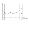
図3は、HDR制御部11の動作の一例を説明するフローチャートである。図4は、画像信号の輝度のヒストグラムの一例を示す図である。
図3のステップS101において、HDR制御部11は、現像処理部10からの画像信号より、図4に示すような輝度のヒストグラムを生成する。
次に、ステップS102において、HDR制御部11は、輝度のヒストグラムより、輝度レベルの或る範囲(領域RESA、RESB)の頻度HA、HBを算出する。この範囲は、例えば、予め設定されるものである。
Here, an example of the control operation of the
FIG. 3 is a flowchart for explaining an example of the operation of the
In step S101 of FIG. 3, the
Next, in step S102, the
次に、ステップS103において、HDR制御部11は、頻度HA、HBと、予め設定された閾値STと、を用いて、例えば、以下の(2)式に示す演算を行ってHDR評価値HDRPを求める。
HDRP=(HA+HB)−ST ・・・(2)
HDR評価値が正の値である場合には、全体的に明るい、全体的に暗い、又は明暗差が大きい場合が考えられるので、HDR処理を行ったほうが良いと考えられる。
Next, in step S103, the
HDRP = (HA + HB) −ST (2)
When the HDR evaluation value is a positive value, it may be considered that it is better to perform the HDR process because it may be bright overall, dark overall, or have a large contrast.
次に、ステップS104において、HDR制御部11は、頻度HAが予め設定された閾値STAを上回るか否かを判定する。この判定の結果、頻度HAが閾値STAを上回る場合にはステップS105へ進み、頻度HAが閾値STAを上回らない場合にはステップS108へ進む。
ステップS105に進むと、HDR制御部11は、頻度HBが予め設定された閾値STBを上回るか否かを判定する。この判定の結果、頻度HBが閾値STBを上回る場合にはステップS106へ進み、頻度HBが閾値STBを上回らない場合にはステップS107へ進む。
Next, in step S104, the
In step S105, the
一方、ステップS108に進むと、HDR制御部11は、頻度HBが予め設定された閾値STBを上回るか否かを判定する。この判定の結果、頻度HBが閾値STBを上回る場合にはステップS109へ進み、頻度HBが閾値STBを上回らない場合にはステップS110へ進む。
ステップS106に進んだ場合には、頻度HA、HBともに閾値STA、STBを上回るため、現像処理部10からの画像は、明暗差の大きい画像であると判断できる。そのため、HDR制御部11は、暗い領域が適正露光となるようなシャッタスピードでの撮影と、明るい領域が適正露光となるようなシャッタスピードでの撮影とを指示する撮像素子制御信号を生成し、HDR評価値と共に予測部13へ出力する。
On the other hand, when proceeding to step S108, the
When the process proceeds to step S106, since the frequencies HA and HB both exceed the threshold values STA and STB, it can be determined that the image from the
ステップS107に進んだ場合には、頻度HAは閾値STAを上回るが、頻度HBは閾値STBを上回らないため、現像処理部10からの画像は、暗い領域が多い画像であると判断できる。そのため、HDR制御部11は、暗い画像が適正露光となるようなシャッタスピードでの撮影と、通常の適正露光となるようなシャッタスピードでの撮影とを指示する撮像素子制御信号を生成し、HDR評価値と共に予測部13へ出力する。
ステップS109に進んだ場合には、頻度HAは閾値STAを上回らないが、頻度HBは閾値STBを上回るため、現像処理部10からの画像は、明るい領域が多い画像であると判断できる。そのため、HDR制御部11は、明るい画像が適正露光となるようなシャッタスピードでの撮影と、通常の適正露光となるようなシャッタスピードでの撮影とを指示する撮像素子制御信号を生成し、HDR評価値と共に予測部13へ出力する。
When the process proceeds to step S107, the frequency HA exceeds the threshold value STA, but the frequency HB does not exceed the threshold value STB, so that the image from the
When the process proceeds to step S109, the frequency HA does not exceed the threshold value STA, but the frequency HB exceeds the threshold value STB, so that the image from the
ステップS110に進んだ場合には、頻度HA、HBともに閾値STA、STBを上回らないため、適正な露光量の領域が多い画像と判断できる。そのため、HDR制御部11は、HDRは不要であると判断し、通常の適正露光となるようなシャッタスピードでの撮影を指示する撮像素子制御信号を生成し、HDR評価値と共に予測部13へ出力する。
本実施形態では、カメラ100は、以上の図3のフローチャートで得られた撮像素子制御信号に基づいて、複数の異なる露光条件で撮影された画像を合成した広ダイナミックレンジ画像を得るダイナミックレンジ拡大処理を実行する。そして、頻度HA、HBと閾値STA、STBとの比較の結果に応じて、ステップS101におけるヒストグラムの生成対象となる画像信号とは異なる露光条件で撮影が実行されることになる。
When the process proceeds to step S110, since both the frequencies HA and HB do not exceed the threshold values STA and STB, it can be determined that the image has a large area with an appropriate exposure amount. Therefore, the
In the present embodiment, the
次に、図5、図6を参照して、本実施形態の特徴の一つである予測部13の動作の一例について説明する。
図5は、予測部13の動作の一例を説明するフローチャートである。図6は、HDR評価値と時刻との関係の一例を示す図であり、HDR評価値を予測する方法の一例を説明する図である。
Next, an example of the operation of the
FIG. 5 is a flowchart for explaining an example of the operation of the
図5のステップS201において、予測部13は、遅延計算部9より遅延時間を取得する。
次に、ステップS202において、予測部13は、HDR制御部11よりHDR評価値と撮像素子制御信号(シャッタスピード等)とを取得する。
次に、ステップS203において、予測部13は、メモリ12に保持してある過去のHDR評価値HDRPを読み出す。
次に、ステップS204において、予測部13は、ステップS201で取得した遅延時間と、ステップS202及びS203で取得したHDR評価値とにより、図6の破線のように線形補間によって遅延時間が経過した後のHDR評価値を予測(導出)する。
In step S <b> 201 of FIG. 5, the
Next, in step S202, the
Next, in step S203, the
Next, in step S204, the
次に、ステップS205において、予測部13は、ステップS204で予測したHDR評価値が正の値を取るか否かを判定する。この判定の結果、HDR評価値HDRPの予測値が正の値を取る場合にはステップS206へ進み、HDR評価値HDRPの予測値が負の値または0を取る場合にはステップS207へ進む。
ステップS206に進んだ場合には、HDR評価値の予測値が正の値である。したがって、画像が全体的に明るい、全体的に暗い、明暗差が大きい、の何れかである場合が考えられるので、HDR処理を行ったほうが良いと考えられる。そこで、予測部13は、カメラ100の制御を変更する(HDR処理を行う)という制御信号を生成し、撮像素子制御信号と共に通信IF部8へ出力し、ステップS208へ進む。
Next, in step S205, the
When the process proceeds to step S206, the predicted HDR evaluation value is a positive value. Therefore, the case where the image is either entirely bright, entirely dark, or has a large difference in brightness is considered, and it is considered better to perform the HDR process. Therefore, the
ステップS207に進んだ場合には、HDR評価値の予測値が負の値または0であり、適正な露光量で撮影されていると考えられる。そこで、予測部13は、HDR処理は不要と判断し、カメラ100の制御を変えない(HDR処理を行わない)という制御信号を生成し、撮像素子制御信号と共に通信IF部8へ出力し、ステップS208へ進む。
ステップS208に進むと、予測部13は、ステップS202で取得したHDR評価値HDRPをメモリ12に書き込む。
When the process proceeds to step S207, the predicted HDR evaluation value is a negative value or 0, and it is considered that the image is taken with an appropriate exposure amount. Therefore, the
In step S208, the
以上のように本実施形態では、予測部13は、現在(最新)のHDR評価値と過去のHDR評価値とに基づいて、生成対象の撮像素子制御情報を適用する画像に対応するHDR評価値の予測値を計算する。そして、HDR評価値の予測値に応じてHDR処理を行うか否かを決定する。したがって、カメラ100本体で設定される際の撮影シーンを予測した撮像素子制御信号を生成し、サーバー200より送信することができ、撮影シーンに合わせたカメラ100本体の制御を行うことができるようになる。
As described above, in the present embodiment, the
<変形例>
本実施形態では、図5のステップS205でHDR評価値の予測値が正の値を取るか否かを判定し、この判定の結果に応じて、HDR制御部11で生成された撮像素子制御信号を採用するか否かを決定する場合を例に挙げて説明した。しかしながら、必ずしもこのようにする必要はない。例えば、HDR評価値の予測値を用いて、図3のステップS104〜S110の処理を行うようにしてもよい。
<Modification>
In the present embodiment, it is determined in step S205 in FIG. 5 whether or not the predicted value of the HDR evaluation value is a positive value, and the image sensor control signal generated by the
また、本実施形態では、HDR処理を用いた場合を例に挙げて説明した。しかしながら、カメラ100における撮像動作を制御するものであれば、HDR処理以外の処理を行ってもよい。図7〜図10を参照しながら、このような処理の一例を以下に説明する。
図7は、モード制御部71の構成の一例を示すブロック図である。図7に示すモード制御部71は、図1に示したHDR制御部11の代わりになるものである。図8は、モード制御部71の動作の一例を説明するフローチャートである。図8は、図3の代わりになるものである。図9は、スポーツモード評価値と動き量との関係の一例を示す図であり、スポーツモード評価値の算出方法の一例を説明する図である。
In the present embodiment, the case where the HDR process is used has been described as an example. However, any process other than the HDR process may be performed as long as it controls the imaging operation of the
FIG. 7 is a block diagram illustrating an example of the configuration of the
図8のステップS301において、動きベクトル算出部71aは、輝度信号と色信号とに基づいて動きベクトルを算出する。
次に、ステップS302において、被写体検出部71bは、輝度信号に基づいて被写体を検出する。
In step S301 in FIG. 8, the motion
Next, in step S302, the
次に、ステップS302において、スポーツモード評価値算出部71cは、ステップS302における被写体の検出の結果に基づいて、画像に人が含まれているか否かを判定する。
この判定の結果、画像に人が含まれていない場合には、ステップS104に進み、スポーツモード評価値算出部71cは、スポーツモード評価値をゼロとする。
次に、ステップS105において、スポーツモード評価値算出部71cは、被写体に人がいない場合の所定のシャッタスピードでの撮影を指示する撮像素子制御信号を生成し、スポーツモード評価値と共に予測部13へ出力する。
Next, in step S302, the sports mode evaluation
If the result of this determination is that no person is included in the image, the process proceeds to step S104, and the sports mode evaluation
Next, in step S105, the sports mode evaluation
一方、画像に人が含まれている場合には、ステップS106に進み、スポーツモード評価値算出部71cは、ステップS301で算出された動きベクトル(動き量)に基づいて、スポーツモード評価値を算出する。例えば、図9に示す関係を示す情報に基づいてスポーツモード評価値を算出することができる。図9に示すように、動き量(動きベクトルの長さ)が大きいほど、スポーツモード評価値を大きくする。
次に、ステップS107において、スポーツモード評価値算出部71cは、ステップS106で算出されたスポーツモード評価値に応じたシャッタスピードでの撮影を指示する撮像素子制御信号を生成し、スポーツモード評価値と共に予測部13へ出力する。ここでは、スポーツモード評価値が大きくなるほどシャッタスピードが速くなるようにする。
On the other hand, if a person is included in the image, the process proceeds to step S106, and the sports mode evaluation
Next, in step S107, the sports mode evaluation
予測部13は、HDR評価値の予測値と同様に、遅延時間が経過した後のスポートモード評価値の予測値を導出する。そして、スポートモード評価値の予測値が閾値を上回る場合、予測部13は、撮影シーンがスポーツモードに対応するシーンに移行したと判断し、カメラ100の制御を変更するという制御信号を生成し、撮像素子制御信号と共に通信IF部8へ出力する。一方、スポートモード評価値の予測値が閾値を上回らない場合、予測部13は、撮影シーンがスポーツモードに対応するシーンに移行していないと判断し、カメラ100の制御を変えないという制御信号を生成し、撮像素子制御信号と共に通信IF部8へ出力する。
The
このように、撮影される画像に対する画像処理や、自動で判別した撮影シーンに合わせたレンズや撮像素子の制御を行う処理といった、カメラ100における撮像動作を制御する場合に、本実施形態の手法を適用できる。輝度信号、色信号、被写体の検出の結果等の撮影シーンが反映された評価値と遅延時間とから、遅延時間が経過した後の撮影シーンを予測し、予測に基づき光学系制御信号や撮像素子制御信号を生成し、サーバー200からカメラ100本体に送信する。これにより、例えば、カメラ100本体にないモードでのカメラ制御も可能となる。
In this way, the method of the present embodiment is used when controlling the imaging operation of the
また、遅延時間が所定時間以上である場合は予測精度が低くなる場合があるため、撮像素子制御信号および撮像素子制御識別情報をサーバー200からカメラ100に送らないようにすることもできる。このようにすれば、誤ったカメラ制御が行われることを防止することができる。
また、本実施形態では、カメラ100からサーバー200に情報を送信する場合を例に挙げて説明した。しかしながら、カメラ100から、カメラ100及びサーバー200とは別の外部装置を介してサーバー200に情報を送信してもよい。同様に、サーバー200からカメラ100を送信先として送信される情報も、カメラ100及びサーバー200とは別の外部装置を介してカメラ100に送信してもよい。
また、本実施形態では、カメラ100からサーバー200に画像信号を画像情報の一例として送信するようにした。しかしながら、必ずしもこのようにする必要はなく、画像信号の代わりに、画像の特徴量をカメラ100からサーバー200に送信してもよいし、これらの両方をカメラ100からサーバー200に送信してもよい。
また、本実施形態では、サーバー処理の順序を、現像処理A、HDR評価値算出処理B、遅延計算処理C、撮像素子制御情報および撮像素子制御識別情報生成処理Dの順にした。しかしながら、遅延計算処理Cを実行するタイミングは、このようなタイミングに限定されない。例えば、撮像素子制御情報および撮像素子制御識別情報生成処理Dの後に、遅延計算処理Cを行ってもよいし、サーバー処理におけるその他のタイミングで遅延計算処理Cを行ってもよい。
Further, when the delay time is equal to or longer than the predetermined time, the prediction accuracy may be lowered. Therefore, the image sensor control signal and the image sensor control identification information may not be sent from the
In the present embodiment, the case where information is transmitted from the
In the present embodiment, an image signal is transmitted from the
In this embodiment, the order of server processing is the order of development processing A, HDR evaluation value calculation processing B, delay calculation processing C, image sensor control information, and image sensor control identification information generation processing D. However, the timing for executing the delay calculation process C is not limited to such timing. For example, the delay calculation process C may be performed after the image sensor control information and the image sensor control identification information generation process D, or the delay calculation process C may be performed at other timings in the server process.
(第2の実施形態)
次に、本発明の第2の実施形態について説明する。
前述した第1の実施形態では、撮像素子3で得られた画像をそのままカメラ100からサーバー200へ送信する場合を例に挙げて説明した。これに対し、本実施形態では、カメラ100からサーバー200へ送信する画像の情報量を制御する。このように本実施形態では、第1の実施形態に対し、カメラ100からサーバー200へ送信する画像の情報量を制御する構成が付加されたものである。すなわち、本実施形態では、カメラ100本体に情報量制御部14を追加し、予測部13が制御信号および撮像素子制御信号だけでなく、情報量制御信号も生成する。したがって、本実施形態の説明において第1の実施形態と同一の部分については、図1〜図9に付した符号と同一の符号を付す等して詳細な説明を省略する。
(Second Embodiment)
Next, a second embodiment of the present invention will be described.
In the first embodiment described above, the case where an image obtained by the image sensor 3 is transmitted as it is from the
図10は、カメラシステムの構成の一例を示すブロック図である。
図10おいて、情報量制御部14は、予測部13からの情報量制御信号に基づいて、撮像素子3からの画像の縮小画像を作成し、当該縮小画像を通信IF部6へ出力する。
予測部13は、現在および過去のHDR評価値の変化量が大きくなればなるほど、撮像素子3からの画像の情報量を減らすようにするための情報量制御信号を生成し、通信IF部8へ出力する。
FIG. 10 is a block diagram illustrating an example of the configuration of the camera system.
In FIG. 10, the information
The
図11は、通信IF部6、通信IF部8、および遅延計算部9の動作の一例を説明するタイミングチャートである。
予測部13は、時刻t23に情報制御信号の生成を開始する。前述したように、情報制御信号は、画像を間引くことなどによって縮小画像を生成し、その縮小画像をカメラ100からサーバー200に送信することで情報量を減らすことを指示する信号である。そして、通信IF部6は、時刻t25にその情報制御信号の受信を完了する。以後、サーバー200は、常に情報量を減らすという情報制御信号が生成し、その情報制御信号をカメラ100に送信するものとする。
FIG. 11 is a timing chart for explaining an example of operations of the communication IF
The
カメラ100は、時刻t26に、通常通り画像RA4の撮影を行う。その後、時刻t29に、画像RA4の撮影が完了すると共に、カメラ100からサーバー200へ画像の送信が開始される。
ここで、カメラ100は、サーバー200から情報量を減らす情報制御信号を受信している。したがって、情報量制御部14は、その情報制御信号に従い情報量を減らし、期間tsr1または期間tsr2、tsr3よりも短い期間tsr4の時間をかけて画像RA4を送信する。図4では、画像の縮小倍率を1/2倍としているため、2フレームに1度の画像の送信を行う場合を例に挙げて示す。
The
Here, the
また、サーバー200は、カメラ100から送信された画像RA4の画像信号の受信を、カメラ100が当該画像信号の送信を開始した時刻よりもわずかに遅れて開始し、当該画像信号の送信時間と同じ時間をかけて時刻t36で受信することを想定している。
画像RA4が縮小されていることから、時刻t36で開始する画像RA4に対するサーバー処理では、現像処理AとHDR評価値算出Bの処理時間が短縮され、それぞれ期間tsp12、tsp13の時間をかけて行われる。
期間tss3は、サーバー処理で得られた撮像素子制御情報および撮像素子制御識別情報生成をサーバー200からカメラ100に送信するためにかかる時間を示す。
サーバー処理より送信された撮像素子制御情報および撮像素子制御識別情報は、カメラ100側で同じ時間をかけて受信される。そして、時刻t40で開始される画像RA6の撮影に反映する準備が行われる。
In addition, the
Since the image RA4 is reduced, in the server processing for the image RA4 starting at time t36, the processing time of the development processing A and the HDR evaluation value calculation B is shortened and is performed over the time periods tsp12 and tsp13, respectively. .
The period tss3 indicates the time taken to transmit the image sensor control information and the image sensor control identification information generated by the server process from the
The image sensor control information and the image sensor control identification information transmitted from the server process are received over the same time on the
ここで、遅延時間Tsdly'は、画像RA4をサーバー処理している時の遅延計算開始時刻t39と、画像RA4をサーバー処理し、当該サーバー処理で生成された撮像素子制御情報を用いて撮影した画像をサーバー処理する時の遅延計算開始時刻t61とを用いると、例えば、以下の(3)式に示す演算により計算される。遅延計算部9は、計算した遅延時間Tsdly'を予測部13へ出力する。
Tsdly'=t61−t39 ・・・(3)
Here, the delay time Tsdly ′ is a delay calculation start time t39 when the image RA4 is server-processed, and an image captured using the image sensor control information generated by the server process of the image RA4 and the server process. When the delay calculation start time t61 at the time of server processing is used, for example, it is calculated by the calculation shown in the following equation (3). The
Tsdly ′ = t61−t39 (3)
このように、カメラ100側から縮小画像をサーバー200に送信することで、画像の送信時間およびサーバー処理にかかる時間を減らすことができ、その結果、遅延時間を短縮することができる。
As described above, by transmitting the reduced image from the
次に、図12のフローチャートを参照しながら、本実施形態の特徴の一つである予測部13の動作の一例について説明する。
図12のステップS401において、予測部13は、遅延計算部9より遅延時間を取得する。
次に、ステップS402において、予測部13は、HDR制御部11よりHDR評価値と撮像素子制御信号とを取得する。
次に、ステップS403において、予測部13は、メモリ12に保持してある過去のHDR評価値を読み出す。
次に、ステップS404において、予測部13は、ステップS401で取得した遅延時間と、ステップS402及びHDR評価値より、遅延時間が経過した後のHDR評価値を予測する(図6を参照)。
Next, an example of the operation of the
In step S <b> 401 of FIG. 12, the
Next, in step S <b> 402, the
Next, in step S403, the
Next, in step S404, the
次に、ステップS405において、予測部13は、ステップS404で予測したHDR評価値が正の値を取るか否かを判定する。この判定の結果、HDR評価値HDRPの予測値が正の値を取る場合にはステップS406へ進み、HDR評価値の予測値が負の値または0を取る場合にはステップS407へ進む。
ステップS406に進んだ場合には、HDR評価値の予測値が正の値である。したがって、画像が全体的に明るい、全体的に暗い、明暗差が大きい、の何れかである場合が考えられるので、HDR処理を行ったほうが良いと考えられる。そこで、予測部13は、カメラ100の制御を変更する(HDR処理を行う)という制御信号を生成し、撮像素子制御信号と共に通信IF部8へ出力し、ステップS408へ進む。
ステップS407に進んだ場合には、HDR評価値の予測値が負の値または0であり、適正な露光量で撮影されていると考えられる。そこで、予測部13は、HDR処理は不要と判断し、カメラ100の制御を変えない(HDR処理を行わない)という制御信号を生成し、撮像素子制御信号と共に通信IF部8へ出力し、ステップS408へ進む。
Next, in step S405, the
When the process proceeds to step S406, the predicted HDR evaluation value is a positive value. Therefore, the case where the image is either entirely bright, entirely dark, or has a large difference in brightness is considered, and it is considered better to perform the HDR process. Therefore, the
When the process proceeds to step S407, the predicted HDR evaluation value is a negative value or 0, and it is considered that the image is taken with an appropriate exposure amount. Therefore, the
次に、ステップS408において、予測部13は、HDR評価値の変動量を算出する。
図13は、HDR評価値と時刻との関係の一例を示す図であり、HDR評価値の変動量を算出する方法の一例を説明する図である。
図13において、時刻tm3、tm2、tm1、t0、t1、t2'、t3'、t4'は、あるHDR評価値が算出された時刻を示す。時刻HDRPtm3、HDRPtm2、HDRPtm1、HDRPt0、HDRPt1、HDRPt2'、 HDRPt3'、HDRPt4'は、それぞれ時刻tm3、tm2、tm1、t0、t1、t2'、t3'、t4'に生成されたHDR評価値を示す。HDR評価値の予測値tm3totm2、tm2totm1、tm1tot0、t0tot1、t1tot2'、t2'tot3'は、それぞれ時刻tm2、tm1、t0、t1、t2'、t3'において線形補間により求められたHDR評価値の予測結果を示す。
また、例えば、時刻t0におけるHDR評価値の変動量alは、以下の(4)式に示す演算を用いて求められる。
al=(HDRPt0−HDRPtm1)÷(t0−tm1) ・・・(4)
Next, in step S408, the
FIG. 13 is a diagram illustrating an example of the relationship between the HDR evaluation value and the time, and is a diagram illustrating an example of a method for calculating the fluctuation amount of the HDR evaluation value.
In FIG. 13, times tm3, tm2, tm1, t0, t1, t2 ′, t3 ′, and t4 ′ indicate times at which certain HDR evaluation values are calculated. Time HDRPtm3, HDRPtm2, HDRPtm1, HDRPt0, HDRPt1, HDRPt2 ', HDRPt3', HDRPt4 'indicate the HDR evaluation values generated at times tm3, tm2, tm1, t0, t1, t2', t3 ', and t4', respectively. . Predicted HDR evaluation values tm3totm2, tm2totm1, tm1tot0, t0tot1, t1tot2 ', and t2'tot3' are predictions of HDR evaluation values obtained by linear interpolation at times tm2, tm1, t0, t1, t2 ', and t3', respectively. Results are shown.
Further, for example, the fluctuation amount al of the HDR evaluation value at time t0 is obtained using the calculation shown in the following equation (4).
al = (HDRPt0−HDRPtm1) ÷ (t0−tm1) (4)
このように、予測部13は、各時刻におけるHDR評価値の変動量を求め、ステップS409へ進む。
ステップS409に進むと、予測部13は、ステップS408で求めたHDR評価値の変動量を用いて、情報量制御信号を生成する。
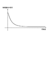
図14は、情報量制御信号と、HDR評価値の変動量との関係の一例を示す図であり、情報量制御信号を生成する方法の一例を説明する図である。尚、図14の縦軸の情報量制御信号の値は、情報量の多さを表すものである。
各時刻におけるHDR評価値の変動量が大きくなるほど、HDR評価値が正の値となる時刻が早まる。そこで、HDR評価値の変動量が大きくなるほど情報量を減らすことで遅延時間Tsdly'を短縮し、HDR評価値を早期に算出できるようにする。
そして、ステップS410において、予測部13は、ステップS402で取得したHDR評価値をメモリ12に書き込む。
In this way, the
In step S409, the
FIG. 14 is a diagram illustrating an example of the relationship between the information amount control signal and the HDR evaluation value variation, and is a diagram illustrating an example of a method for generating the information amount control signal. The value of the information amount control signal on the vertical axis in FIG. 14 represents the amount of information.
As the amount of change in the HDR evaluation value at each time increases, the time at which the HDR evaluation value becomes a positive value is advanced. Therefore, the delay time Tsdly ′ is shortened by reducing the information amount as the fluctuation amount of the HDR evaluation value increases, so that the HDR evaluation value can be calculated early.
In step S410, the
以上のように本実施形態では、各時刻におけるHDR評価値の変動量が大きくなるほど、カメラ100からサーバー200に送信する画像の情報量を減らすようにした。したがって、第1の実施形態で説明した効果に加え、遅延時間Tsdly'を短縮し、HDR評価値を早期に算出することができるという効果が得られる。したがって、HDR評価値(撮影シーン)の予測精度を向上させることができる。
本実施形態においても、第1の実施形態で説明した種々の変形例を採用することができる。
As described above, in this embodiment, the amount of image information transmitted from the
Also in the present embodiment, various modifications described in the first embodiment can be employed.
(第3の実施形態)
次に、本発明の第3の実施形態について説明する。
前述した第1の実施形態では、HDR評価値の予測値の判定結果のみに応じてカメラ100の制御を決定する場合を例に挙げて説明した。これに対して、本実施形態では、所定回数以上連続で同じHDR評価値が得られている場合に、HDR評価値の予測値の判定結果に応じた制御を行う。このように本実施形態と第1の実施形態とは、HDR評価値の予測値の判定を行った後の処理が主として異なる。すなわち、本実施形態では、予測部13は、HDR評価値の予測値の判定結果が、所定回数以上連続で同じとなった場合に、判定結果に応じた制御信号を通信IF部8へ出力する。したがって、本実施形態の説明において第1の実施形態と同一の部分については、図1〜図9に付した符号と同一の符号を付す等して詳細な説明を省略する。
(Third embodiment)
Next, a third embodiment of the present invention will be described.
In the first embodiment described above, the case where the control of the
図15は、本実施形態の特徴の一つである予測部13の動作の一例を説明するフローチャートである。
図15のステップS501において、予測部13は、遅延計算部9より遅延時間を取得する。
次に、ステップS502において、予測部13は、HDR制御部11よりHDR評価値と撮像素子制御信号とを取得する。
次に、ステップS503において、予測部13は、メモリ12に保持してある過去のHDR評価値を読み出す。
次に、ステップS504において、予測部13は、ステップS501で取得した遅延時間と、ステップS502及びS503で取得したHDR評価値とにより、遅延時間が経過後のHDR評価値を予測する(図6を参照)。
FIG. 15 is a flowchart for explaining an example of the operation of the
In step S <b> 501 of FIG. 15, the
Next, in step S <b> 502, the
Next, in step S <b> 503, the
Next, in step S504, the
次に、ステップS505において、予測部13は、ステップS504で予測したHDR評価値が正の値を取るか否かを判定する。この判定の結果、HDR評価値の予測値が正の値を取る場合にはステップS506へ進み、HDR評価値の予測値が負の値または0を取る場合にはステップS509へ進む。
Next, in step S505, the
ステップS506に進むと、予測部13は、HDR評価値の予測値が所定回数以上連続で正の値を示したか否かを判定する。この判定の結果、HDR評価値の予測値が所定回数以上連続で正の値を取る場合にはステップS507へ進み、そうでない場合にはステップS508へ進む。
ステップS507に進んだ場合には、HDR評価値の予測値が所定回数以上連続で正の値を示している。このため、予測部13は、撮影シーンが安定していると判断し、カメラ100の制御を変更する(HDR処理を行う)という制御信号を生成し、撮像素子制御信号とともに通信IF部8へ出力し、ステップS512へ進む。
In step S506, the
When the process proceeds to step S507, the predicted value of the HDR evaluation value indicates a positive value continuously for a predetermined number of times or more. For this reason, the
ステップS508に進んだ場合には、HDR評価値の予測値が所定回数以上連続で正の値を示していない。このため、予測部13は、撮影シーンが不安定であると判断し、カメラ100の制御を変えない(HDR処理を行わない)という制御信号を生成し、撮像素子制御信号と共に通信IF部8へ出力し、ステップS512へ進む。
When the process proceeds to step S508, the predicted HDR evaluation value is not continuously positive for a predetermined number of times. For this reason, the
前述したように、ステップ505において、HDR評価値の予測値が負の値または0を取ると判定された場合にはステップS509へ進む。ステップS509に進むと、予測部13は、HDR評価値の予測値が所定回数以上連続で負の値または0を示したか否かを判定する。この判定の結果、HDR評価値の予測値が所定回数以上連続で負の値または0を示す場合にはステップS510へ進み、そうでない場合にはステップS511へ進む。
ステップS510に進んだ場合には、HDR評価値の予測値が所定回数以上連続で負の値または0を示している。このため、予測部13は、撮影シーンが安定していると判断し、カメラ100の制御を変えない(HDR処理を行わない)という制御信号を生成し、撮像素子制御信号と共に通信IF部8へ出力し、ステップS512へ進む。
As described above, if it is determined in
When the processing proceeds to step S510, the predicted value of the HDR evaluation value indicates a negative value or 0 continuously for a predetermined number of times or more. For this reason, the
ステップS511に進んだ場合には、HDR評価値の予測値が所定回数以上連続で負の値または0を示していない。このため、予測部13は、撮影シーンが不安定であると判断し、カメラ100の制御を変更する(HDR処理を行う)という制御信号を生成し、撮像素子制御信号と共に通信IF部8へ出力し、ステップS512へ進む。
ステップS512に進むと、予測部13は、ステップS502で取得したHDR評価値HDRPをメモリ12に書き込む。
When the process proceeds to step S511, the predicted value of the HDR evaluation value does not indicate a negative value or 0 continuously for a predetermined number of times or more. For this reason, the
In step S512, the
以上のように本実施形態では、HDR評価値の予測値の判定の結果が所定回数以上連続で同じであるという所定の同一の条件を連続して満たす判定された場合に、撮影シーンが安定していると判断する。そして、当該判定の結果に基づいて、カメラ100の制御を変更するか否かを示す制御信号を生成する。したがって、撮影シーンが不安定な場合でも、カメラ100の制御を安定して行うことができる。
本実施形態においても、第1の実施形態で説明した種々の変形例を採用することができる。また、本実施形態を第2の実施形態に適用することもできる。
As described above, in the present embodiment, the shooting scene is stabilized when it is determined that the result of determination of the predicted value of the HDR evaluation value continuously satisfies the same predetermined condition that it is the same continuously for a predetermined number of times or more. Judge that Then, based on the result of the determination, a control signal indicating whether to change the control of the
Also in the present embodiment, various modifications described in the first embodiment can be employed. In addition, this embodiment can be applied to the second embodiment.
尚、前述した実施形態は、何れも本発明を実施するにあたっての具体化の例を示したものに過ぎず、これらによって本発明の技術的範囲が限定的に解釈されてはならないものである。すなわち、本発明はその技術思想、又はその主要な特徴から逸脱することなく、様々な形で実施することができる。 The above-described embodiments are merely examples of implementation in carrying out the present invention, and the technical scope of the present invention should not be construed in a limited manner. That is, the present invention can be implemented in various forms without departing from the technical idea or the main features thereof.
(その他の実施例)
本発明は、以下の処理を実行することによっても実現される。即ち、まず、以上の実施形態の機能を実現するソフトウェア(コンピュータプログラム)を、ネットワーク又は各種記憶媒体を介してシステム或いは装置に供給する。そして、そのシステム或いは装置のコンピュータ(又はCPUやMPU等)が当該コンピュータプログラムを読み出して実行する。
(Other examples)
The present invention is also realized by executing the following processing. That is, first, software (computer program) for realizing the functions of the above embodiments is supplied to a system or apparatus via a network or various storage media. Then, the computer (or CPU, MPU, etc.) of the system or apparatus reads and executes the computer program.
100 カメラ、200 サーバー、300 インターネット 100 cameras, 200 servers, 300 Internet
Claims (16)
前記撮像装置により撮像された画像信号および前記画像信号の特徴量の少なくとも一方を前記画像情報として前記撮像装置から受信する受信手段と、
前記受信手段により受信された前記画像情報に基づいて、当該画像情報が得られたときの撮影シーンの評価値を導出する導出手段と、
前記導出手段により導出された評価値を記憶媒体に記憶する記憶手段と、
前記記憶手段により記憶された複数の評価値を用いて、前記通信ネットワークを介した撮像制御によって発生する遅延時間に応じて決定される撮像時点における撮影シーンの評価値を予測し、予測された前記評価値に基づいて前記制御信号を生成する生成手段と、
前記生成手段により生成された前記制御信号を、前記撮像装置に送信する送信手段と、を有することを特徴とする制御装置。 A control device that receives image information from an imaging device via a communication network and transmits a control signal related to imaging to the imaging device based on the image information,
Receiving means for receiving from said image pickup device to hand also reduce the feature quantity of the captured image signal and the image signal as the image information by the imaging device,
Deriving means for deriving an evaluation value of a shooting scene when the image information is obtained based on the image information received by the receiving means;
Storage means for storing the evaluation value derived by the derivation means in a storage medium;
Using the plurality of evaluation values stored by the storage means, the evaluation value of the shooting scene at the time of imaging determined according to the delay time generated by the imaging control via the communication network is predicted, and the predicted Generating means for generating the control signal based on an evaluation value ;
Control device according to claim Rukoto to have a, and transmitting means for transmitting the control signal generated by the generation unit, on the imaging device.
前記評価値の変動量に基づいて、前記画像情報の情報量を決定する決定手段と、を有し、
前記送信手段は、前記決定手段により決定された前記画像情報の情報量を示す情報を、前記撮像装置に送信し、
前記受信手段は、前記送信手段により前記画像情報の情報量を示す情報が送信された後に、前記画像情報の情報量に応じた情報量を有する前記画像情報を受信し、
前記決定手段は、前記評価値の変動量が大きいほど、前記画像情報の情報量が少なくなるように、前記画像情報の情報量を決定することを特徴とする請求項1に記載の制御装置。 Calculating means for calculating a fluctuation amount of the evaluation value based on at least two evaluation values derived by the deriving means at different times;
Determining means for determining an information amount of the image information based on a fluctuation amount of the evaluation value;
The transmission unit, the information indicating the information amount of the image information determined by the determining means, and transmitted to the imaging device,
The receiving unit receives the image information having an information amount corresponding to the information amount of the image information after the information indicating the information amount of the image information is transmitted by the transmitting unit;
The control device according to claim 1, wherein the determination unit determines the information amount of the image information so that the information amount of the image information decreases as the variation amount of the evaluation value increases.
前記生成手段は、予測された前記評価値に基づいて、複数の異なる露光条件で撮影された画像を合成して広ダイナミックレンジ画像を得るダイナミックレンジ拡大処理を行うか否かを判定し、前記ダイナミックレンジ拡大処理を行うと判定すると、前記ダイナミックレンジ拡大処理を行うことを示す信号を前記制御信号として生成することを特徴とする請求項1〜5の何れか1項に記載の制御装置。 The evaluation value is a value based on a luminance signal in the image information,
The generation unit, based on predicted by said evaluation value, it is judged whether or not to perform the dynamic range expansion processing to obtain a plurality of different combined and wide dynamic range image captured by the image exposure conditions, the If it is determined to perform the dynamic range expansion process, the control device according to a signal indicating that performing the dynamic range expansion processing in any one of claim 1 to 5, characterized in that generated as said control signal.
前記生成手段は、予測された前記評価値に基づいて、前記撮像装置が備える撮像素子の制御の変更を伴う撮影シーンの移行が発生するか否かを判定し、前記撮像装置が備える撮像素子の制御の変更を伴う撮影シーンの移行が発生すると判定すると、当該撮影シーンの移行に応じた前記撮像素子の制御の内容を示す信号を前記制御信号として生成することを特徴とする請求項1〜5の何れか1項に記載の制御装置。 The evaluation value is a value based on a motion vector obtained based on a luminance signal and a color signal in the image information,
The generation unit, based on predicted by said evaluation value, it is determined whether the transition of the shooting scene involving a change of control of the imaging device the imaging device is provided to generate an imaging device wherein the imaging device comprises 2. When it is determined that a shooting scene shift accompanied by a change in control occurs, a signal indicating the control content of the image sensor corresponding to the shooting scene shift is generated as the control signal. The control device according to any one of 5 .
前記撮像装置により撮像された画像信号および前記画像信号の特徴量の少なくとも一方を前記画像情報として前記撮像装置から受信する受信工程と、
前記受信工程により受信された前記画像情報に基づいて、当該画像情報が得られたときの撮影シーンの評価値を導出する導出工程と、
前記導出工程により導出された評価値を記憶媒体に記憶する記憶工程と、
前記記憶工程により記憶された複数の評価値を用いて、前記通信ネットワークを介した撮像制御によって発生する遅延時間に応じて決定される撮像時点における撮影シーンの評価値を予測し、予測された前記評価値に基づいて前記制御信号を生成する生成工程と、
前記生成工程により生成された前記制御信号を、前記撮像装置に送信する送信工程と、を有することを特徴とする撮像制御方法。 An imaging control method for receiving image information from an imaging device via a communication network and transmitting a control signal related to imaging to the imaging device based on the image information,
A reception step of receiving from said imaging device a hand also reduce the feature quantity of the captured image signal and the image signal as the image information by the imaging device,
Based on the image information received by the receiving step, a derivation step for deriving an evaluation value of a shooting scene when the image information is obtained;
A storage step of storing the evaluation value derived by the derivation step in a storage medium;
A plurality of evaluation values stored in the storage step are used to predict an evaluation value of a shooting scene at an imaging point determined according to a delay time generated by imaging control via the communication network, and the predicted value Generating step for generating the control signal based on the evaluation value ;
Imaging control method comprising Rukoto that the control signal generated by the generation process, have a, sending a signal process that sends to said image pickup device.
前記評価値の変動量に基づいて、前記画像情報の情報量を決定する決定工程と、を有し、
前記送信工程は、前記決定工程により決定された前記画像情報の情報量を示す情報を、前記撮像装置に送信し、
前記受信工程は、前記送信工程により前記画像情報の情報量を示す情報が送信された後に、前記画像情報の情報量に応じた情報量を有する前記画像情報を受信し、
前記決定工程は、前記評価値の変動量が大きいほど、前記画像情報の情報量が少なくなるように、前記画像情報の情報量を決定することを特徴とする請求項8に記載の撮像制御方法。 A calculation step of calculating a variation amount of the evaluation value based on at least two evaluation values derived by the derivation step at different times;
A determination step of determining an information amount of the image information based on a variation amount of the evaluation value,
It said transmitting step, information indicating an information amount of the image information determined by the determination step, and transmitted to the imaging device,
The receiving step receives the image information having an information amount corresponding to the information amount of the image information after the information indicating the information amount of the image information is transmitted by the transmitting step;
9. The imaging control method according to claim 8 , wherein the determining step determines the information amount of the image information so that the information amount of the image information decreases as the variation amount of the evaluation value increases. .
前記生成工程は、予測された前記評価値に基づいて、複数の異なる露光条件で撮影された画像を合成して広ダイナミックレンジ画像を得るダイナミックレンジ拡大処理を行うか否かを判定し、前記ダイナミックレンジ拡大処理を行うと判定すると、前記ダイナミックレンジ拡大処理を行うことを示す信号を前記制御信号として生成することを特徴とする請求項8〜12の何れか1項に記載の撮像制御方法。 The evaluation value is a value based on a luminance signal in the image information,
Said generating step, based on predicted by said evaluation value, it is judged whether or not to perform the dynamic range expansion processing to obtain a plurality of different combined and wide dynamic range image captured by the image exposure conditions, the 13. The imaging control method according to claim 8 , wherein if it is determined that a dynamic range expansion process is to be performed, a signal indicating that the dynamic range expansion process is to be performed is generated as the control signal.
前記生成工程は、予測された前記評価値に基づいて、前記撮像装置が備える撮像素子の制御の変更を伴う撮影シーンの移行が発生するか否かを判定し、前記撮像装置が備える撮像素子の制御の変更を伴う撮影シーンの移行が発生すると判定すると、当該撮影シーンの移行に応じた前記撮像素子の制御の内容を示す信号を前記制御信号として生成することを特徴とする請求項8〜12の何れか1項に記載の撮像制御方法。 The evaluation value is a value based on a motion vector obtained based on a luminance signal and a color signal in the image information,
Said generating step, based on predicted by said evaluation value, it is determined whether the transition of the shooting scene involving a change of control of the imaging device the imaging device is provided to generate an imaging device wherein the imaging device comprises When the migration of the shooting scene with the control change is determined to occur, according to claim 8, characterized in that for generating a signal indicating the contents of control of the image sensor in response to the transition of the captured scene as the control signal The imaging control method according to any one of 12 .
Priority Applications (1)
| Application Number | Priority Date | Filing Date | Title |
|---|---|---|---|
| JP2013061986A JP6141066B2 (en) | 2013-03-25 | 2013-03-25 | Control apparatus, imaging control method, computer program, and imaging system |
Applications Claiming Priority (1)
| Application Number | Priority Date | Filing Date | Title |
|---|---|---|---|
| JP2013061986A JP6141066B2 (en) | 2013-03-25 | 2013-03-25 | Control apparatus, imaging control method, computer program, and imaging system |
Publications (2)
| Publication Number | Publication Date |
|---|---|
| JP2014187602A JP2014187602A (en) | 2014-10-02 |
| JP6141066B2 true JP6141066B2 (en) | 2017-06-07 |
Family
ID=51834700
Family Applications (1)
| Application Number | Title | Priority Date | Filing Date |
|---|---|---|---|
| JP2013061986A Active JP6141066B2 (en) | 2013-03-25 | 2013-03-25 | Control apparatus, imaging control method, computer program, and imaging system |
Country Status (1)
| Country | Link |
|---|---|
| JP (1) | JP6141066B2 (en) |
Family Cites Families (5)
| Publication number | Priority date | Publication date | Assignee | Title |
|---|---|---|---|---|
| JP2003259204A (en) * | 2002-02-27 | 2003-09-12 | Fuji Photo Film Co Ltd | Digital camera, photographing system and photographing method |
| JP4025865B2 (en) * | 2002-03-14 | 2007-12-26 | コニカミノルタオプト株式会社 | Electronic camera |
| JP4451707B2 (en) * | 2004-04-30 | 2010-04-14 | 富士フイルム株式会社 | Imaging apparatus and imaging method |
| JP4553384B2 (en) * | 2005-09-20 | 2010-09-29 | キヤノン株式会社 | Imaging apparatus and control method therefor, computer program, and storage medium |
| JP5048599B2 (en) * | 2008-06-27 | 2012-10-17 | 富士フイルム株式会社 | Imaging device |
-
2013
- 2013-03-25 JP JP2013061986A patent/JP6141066B2/en active Active
Also Published As
| Publication number | Publication date |
|---|---|
| JP2014187602A (en) | 2014-10-02 |
Similar Documents
| Publication | Publication Date | Title |
|---|---|---|
| JP6439837B2 (en) | Electronic device and display method | |
| US20080002960A1 (en) | Auto-focus apparatus, image-capture apparatus, and auto-focus method | |
| US8994783B2 (en) | Image pickup apparatus that automatically determines shooting mode most suitable for shooting scene, control method therefor, and storage medium | |
| US10944895B2 (en) | Accessory apparatus, image-capturing apparatus, control apparatus, lens apparatus, control method, computer program and storage medium storing computer program | |
| JP5213813B2 (en) | IMAGING DEVICE AND IMAGING DEVICE CONTROL METHOD | |
| US10708503B2 (en) | Image capture system, image capturing apparatus, lens unit, control methods therefor, and storage medium | |
| JP2019092119A (en) | Imaging device, lens device, and control method thereof | |
| US20160088219A1 (en) | Image capture apparatus which controls frame rate based on motion of object, information transmission apparatus, image capture control method, information transmission method, and recording medium | |
| JP5704957B2 (en) | Movie shooting apparatus and control method thereof | |
| CN103379285A (en) | Image capture apparatus, lens unit, communication controlling method, and diaphragm controlling method | |
| US20120321288A1 (en) | Apparatus and method of adjusting automatic focus | |
| JP6356972B2 (en) | RECORDING DEVICE, IMAGING DEVICE, AND RECORDING DEVICE CONTROL METHOD | |
| JP6141066B2 (en) | Control apparatus, imaging control method, computer program, and imaging system | |
| US9100578B2 (en) | Image processing apparatus and control method for the same | |
| JP2014171145A (en) | Image pickup device, image pickup method, and program therefor | |
| CN110870301B (en) | Image display method and device and image processing equipment | |
| JP6032884B2 (en) | IMAGING DEVICE, IMAGING DEVICE CONTROL METHOD, PROGRAM | |
| JP5406619B2 (en) | MOVING IMAGE REPRODUCTION DEVICE, IMAGING DEVICE, CONTROL METHOD THEREOF, AND PROGRAM | |
| JP2020188297A (en) | Imaging apparatus, imaging system, and control method of the same | |
| JP2020205560A (en) | Imaging apparatus and control method of the same | |
| US11050928B2 (en) | Image capturing control apparatus, image capturing apparatus, control method, and storage medium | |
| JP2018201102A (en) | Imaging apparatus | |
| WO2024087183A1 (en) | Imaging device, imaging device control method, and computer program product | |
| JP4613829B2 (en) | Imaging apparatus, control method thereof, and control program | |
| JP2018017751A (en) | Control device, imaging device, lens device, control method, program, and storage medium |
Legal Events
| Date | Code | Title | Description |
|---|---|---|---|
| A621 | Written request for application examination |
Free format text: JAPANESE INTERMEDIATE CODE: A621 Effective date: 20160315 |
|
| A977 | Report on retrieval |
Free format text: JAPANESE INTERMEDIATE CODE: A971007 Effective date: 20161122 |
|
| A131 | Notification of reasons for refusal |
Free format text: JAPANESE INTERMEDIATE CODE: A131 Effective date: 20170110 |
|
| A521 | Request for written amendment filed |
Free format text: JAPANESE INTERMEDIATE CODE: A523 Effective date: 20170301 |
|
| TRDD | Decision of grant or rejection written | ||
| A01 | Written decision to grant a patent or to grant a registration (utility model) |
Free format text: JAPANESE INTERMEDIATE CODE: A01 Effective date: 20170404 |
|
| A61 | First payment of annual fees (during grant procedure) |
Free format text: JAPANESE INTERMEDIATE CODE: A61 Effective date: 20170502 |
|
| R151 | Written notification of patent or utility model registration |
Ref document number: 6141066 Country of ref document: JP Free format text: JAPANESE INTERMEDIATE CODE: R151 |