JP6128564B2 - Gesture motion architecture using proximity sensing - Google Patents
Gesture motion architecture using proximity sensing Download PDFInfo
- Publication number
- JP6128564B2 JP6128564B2 JP2014549106A JP2014549106A JP6128564B2 JP 6128564 B2 JP6128564 B2 JP 6128564B2 JP 2014549106 A JP2014549106 A JP 2014549106A JP 2014549106 A JP2014549106 A JP 2014549106A JP 6128564 B2 JP6128564 B2 JP 6128564B2
- Authority
- JP
- Japan
- Prior art keywords
- proximity sensing
- circuit
- proximity
- digital data
- mode
- Prior art date
- Legal status (The legal status is an assumption and is not a legal conclusion. Google has not performed a legal analysis and makes no representation as to the accuracy of the status listed.)
- Active
Links
- 230000033001 locomotion Effects 0.000 title description 13
- 238000000034 method Methods 0.000 claims description 45
- 230000003750 conditioning effect Effects 0.000 claims description 40
- 230000005672 electromagnetic field Effects 0.000 claims description 24
- 230000008878 coupling Effects 0.000 claims description 18
- 238000010168 coupling process Methods 0.000 claims description 18
- 238000005859 coupling reaction Methods 0.000 claims description 18
- 239000000758 substrate Substances 0.000 claims description 11
- 238000013480 data collection Methods 0.000 claims description 3
- 230000005540 biological transmission Effects 0.000 claims description 2
- 238000009966 trimming Methods 0.000 claims 3
- 230000006854 communication Effects 0.000 description 25
- 238000004891 communication Methods 0.000 description 25
- 238000010586 diagram Methods 0.000 description 8
- 238000012546 transfer Methods 0.000 description 8
- 230000009471 action Effects 0.000 description 7
- 239000002184 metal Substances 0.000 description 7
- 229910052751 metal Inorganic materials 0.000 description 7
- 230000007175 bidirectional communication Effects 0.000 description 5
- 238000001514 detection method Methods 0.000 description 5
- 230000006870 function Effects 0.000 description 5
- 238000005259 measurement Methods 0.000 description 5
- 230000001143 conditioned effect Effects 0.000 description 4
- 238000012986 modification Methods 0.000 description 4
- 230000004048 modification Effects 0.000 description 4
- 230000008859 change Effects 0.000 description 3
- 238000013461 design Methods 0.000 description 3
- 238000011161 development Methods 0.000 description 3
- 230000000694 effects Effects 0.000 description 3
- 238000001914 filtration Methods 0.000 description 3
- 238000003860 storage Methods 0.000 description 3
- 230000001360 synchronised effect Effects 0.000 description 3
- 230000002411 adverse Effects 0.000 description 2
- 238000004458 analytical method Methods 0.000 description 2
- 230000008901 benefit Effects 0.000 description 2
- 230000002457 bidirectional effect Effects 0.000 description 2
- 238000005516 engineering process Methods 0.000 description 2
- 230000003993 interaction Effects 0.000 description 2
- 238000004091 panning Methods 0.000 description 2
- 230000000704 physical effect Effects 0.000 description 2
- 238000003825 pressing Methods 0.000 description 2
- 238000012545 processing Methods 0.000 description 2
- 230000035945 sensitivity Effects 0.000 description 2
- 238000012935 Averaging Methods 0.000 description 1
- 230000006399 behavior Effects 0.000 description 1
- 239000003990 capacitor Substances 0.000 description 1
- 238000006243 chemical reaction Methods 0.000 description 1
- 239000004020 conductor Substances 0.000 description 1
- MPTQRFCYZCXJFQ-UHFFFAOYSA-L copper(II) chloride dihydrate Chemical compound O.O.[Cl-].[Cl-].[Cu+2] MPTQRFCYZCXJFQ-UHFFFAOYSA-L 0.000 description 1
- 230000001419 dependent effect Effects 0.000 description 1
- 239000006185 dispersion Substances 0.000 description 1
- 230000005684 electric field Effects 0.000 description 1
- 230000008030 elimination Effects 0.000 description 1
- 238000003379 elimination reaction Methods 0.000 description 1
- 238000005265 energy consumption Methods 0.000 description 1
- 230000005284 excitation Effects 0.000 description 1
- 238000010304 firing Methods 0.000 description 1
- 230000006872 improvement Effects 0.000 description 1
- 230000010365 information processing Effects 0.000 description 1
- 238000009434 installation Methods 0.000 description 1
- 230000002452 interceptive effect Effects 0.000 description 1
- 238000004519 manufacturing process Methods 0.000 description 1
- 230000007246 mechanism Effects 0.000 description 1
- 238000012544 monitoring process Methods 0.000 description 1
- 230000003287 optical effect Effects 0.000 description 1
- 230000000737 periodic effect Effects 0.000 description 1
- 230000001105 regulatory effect Effects 0.000 description 1
- 230000003252 repetitive effect Effects 0.000 description 1
- 230000004044 response Effects 0.000 description 1
- 230000011664 signaling Effects 0.000 description 1
- 238000001228 spectrum Methods 0.000 description 1
Images


Classifications
-
- G—PHYSICS
- G06—COMPUTING; CALCULATING OR COUNTING
- G06F—ELECTRIC DIGITAL DATA PROCESSING
- G06F3/00—Input arrangements for transferring data to be processed into a form capable of being handled by the computer; Output arrangements for transferring data from processing unit to output unit, e.g. interface arrangements
- G06F3/01—Input arrangements or combined input and output arrangements for interaction between user and computer
- G06F3/03—Arrangements for converting the position or the displacement of a member into a coded form
- G06F3/041—Digitisers, e.g. for touch screens or touch pads, characterised by the transducing means
- G06F3/046—Digitisers, e.g. for touch screens or touch pads, characterised by the transducing means by electromagnetic means
-
- G—PHYSICS
- G01—MEASURING; TESTING
- G01S—RADIO DIRECTION-FINDING; RADIO NAVIGATION; DETERMINING DISTANCE OR VELOCITY BY USE OF RADIO WAVES; LOCATING OR PRESENCE-DETECTING BY USE OF THE REFLECTION OR RERADIATION OF RADIO WAVES; ANALOGOUS ARRANGEMENTS USING OTHER WAVES
- G01S13/00—Systems using the reflection or reradiation of radio waves, e.g. radar systems; Analogous systems using reflection or reradiation of waves whose nature or wavelength is irrelevant or unspecified
- G01S13/02—Systems using reflection of radio waves, e.g. primary radar systems; Analogous systems
- G01S13/04—Systems determining presence of a target
-
- G—PHYSICS
- G06—COMPUTING; CALCULATING OR COUNTING
- G06F—ELECTRIC DIGITAL DATA PROCESSING
- G06F3/00—Input arrangements for transferring data to be processed into a form capable of being handled by the computer; Output arrangements for transferring data from processing unit to output unit, e.g. interface arrangements
- G06F3/01—Input arrangements or combined input and output arrangements for interaction between user and computer
- G06F3/03—Arrangements for converting the position or the displacement of a member into a coded form
- G06F3/041—Digitisers, e.g. for touch screens or touch pads, characterised by the transducing means
- G06F3/044—Digitisers, e.g. for touch screens or touch pads, characterised by the transducing means by capacitive means
-
- G—PHYSICS
- G06—COMPUTING; CALCULATING OR COUNTING
- G06F—ELECTRIC DIGITAL DATA PROCESSING
- G06F2203/00—Indexing scheme relating to G06F3/00 - G06F3/048
- G06F2203/041—Indexing scheme relating to G06F3/041 - G06F3/045
- G06F2203/04102—Flexible digitiser, i.e. constructional details for allowing the whole digitising part of a device to be flexed or rolled like a sheet of paper
-
- G—PHYSICS
- G06—COMPUTING; CALCULATING OR COUNTING
- G06F—ELECTRIC DIGITAL DATA PROCESSING
- G06F2203/00—Indexing scheme relating to G06F3/00 - G06F3/048
- G06F2203/041—Indexing scheme relating to G06F3/041 - G06F3/045
- G06F2203/04107—Shielding in digitiser, i.e. guard or shielding arrangements, mostly for capacitive touchscreens, e.g. driven shields, driven grounds
Landscapes
- Engineering & Computer Science (AREA)
- Physics & Mathematics (AREA)
- General Engineering & Computer Science (AREA)
- Theoretical Computer Science (AREA)
- Radar, Positioning & Navigation (AREA)
- Remote Sensing (AREA)
- General Physics & Mathematics (AREA)
- Human Computer Interaction (AREA)
- Computer Networks & Wireless Communication (AREA)
- Electromagnetism (AREA)
- User Interface Of Digital Computer (AREA)
- Position Input By Displaying (AREA)
Description
(発明の分野)
本発明は、電子デバイスの分野に関し、より具体的には、近接感知を使用して、ジェスチャを検出および解釈するためのアーキテクチャに関する。
(Field of Invention)
The present invention relates to the field of electronic devices, and more particularly to an architecture for detecting and interpreting gestures using proximity sensing.
(関連技術の説明)
ジェスチャ動作とは、消費者製品またはコンピューティングデバイスと相互作用するように意図されたユーザの物理的動作に対する一般的用語である。容量性タッチ感知を使用したジェスチャ動作のよく知られた例は、スマートフォンおよびタブレットコンピュータ等の製品のタッチスクリーン上のイメージを操作するための「はさむ」動作または回転動作である。
(Description of related technology)
Gesture action is a general term for a user's physical action that is intended to interact with a consumer product or computing device. A well-known example of a gesture action using capacitive touch sensing is a “pinching” or rotating action to manipulate images on the touch screen of products such as smartphones and tablet computers.
しかしながら、ジェスチャベースのユーザ入力が望ましい多くの状況では、タッチジェスチャは、安全でも現実的でもない場合がある。運転しながら、ボタンの位置を特定して押下し、GPS表示をパンまたはズームすることは、例えば、運転者の注意を引き過ぎ、安全でなくなり得る。故に、本分野における改良が、望ましい。 However, in many situations where gesture-based user input is desirable, touch gestures may not be safe or realistic. While driving, locating and pressing the button and panning or zooming the GPS display may, for example, draw too much attention from the driver and be unsafe. Therefore, improvements in the field are desirable.
(発明の概要)
一実施形態は、タッチベースのジェスチャが、安全でも現実的でもない場合の状況において、ジェスチャ動作を可能にする、ユーザ近接ジェスチャを検出および解釈するための近接感知システムに関する。近接ジェスチャは、ユーザ(または、ユーザ制御された器具)が、感知要素に物理的にタッチすることを必要としない、ユーザ(または、スタイラス等のユーザ制御された器具)の近接に基づいて感知または検出されるジェスチャである。本開示の実施形態は、近接感知ベースのジェスチャ検出および解釈のためのそのような方法と、本方法を実装するように構成されたシステムとに関する。
(Summary of Invention)
One embodiment relates to a proximity sensing system for detecting and interpreting user proximity gestures that enables gesture operation in situations where touch-based gestures are neither safe nor realistic. Proximity gestures are sensed based on the proximity of a user (or a user-controlled instrument such as a stylus) that does not require the user (or a user-controlled instrument) to physically touch the sensing element. A gesture to be detected. Embodiments of the present disclosure relate to such a method for proximity sensing based gesture detection and interpretation and a system configured to implement the method.
本システムは、複数の近接感知回路と、調整回路と、いくつかの実施形態では、解釈回路とを含んでもよい。近接感知回路はそれぞれ、電磁信号を送信および受信するように構成されたアンテナと、アンテナによって1つ以上の方向に送信される信号を遮蔽するように構成された遮蔽ドライバとを含んでもよい。近接感知回路のそれぞれ、調整回路、および解釈回路はまた、本方法の側面を実装するように構成された論理を含んでもよい。 The system may include a plurality of proximity sensing circuits, an adjustment circuit, and in some embodiments an interpretation circuit. Each proximity sensing circuit may include an antenna configured to transmit and receive electromagnetic signals and a shield driver configured to shield signals transmitted by the antenna in one or more directions. Each of the proximity sensing circuits, the adjustment circuit, and the interpretation circuit may also include logic configured to implement aspects of the method.
調整回路は、近接感知回路のそれぞれに結合されてもよい。一組の実施形態によると、調整回路および複数の近接感知回路のそれぞれは、一方向性データ結合を介して結合されてもよい。調整回路はまた、解釈回路に結合されてもよい。いくつかの実施形態では、本システムはさらに、単一のフレキシブル基板を含んでもよく、その上に、複数の近接感知回路および調整回路が、位置してもよい。この場合、異なる構成要素が、同様に単一のフレキシブル基板上に位置する接続(例えば、通信バス)を介して恒久的に結合されてもよい。他の実施形態では、近接感知回路および調整回路は、単一の基板上に位置しなくてもよく、かつ/または別個の構成要素が、分離可能コネクタを介して結合されるように構成されてもよい。本方法は、以下のように行なわれてもよい。 A conditioning circuit may be coupled to each of the proximity sensing circuits. According to one set of embodiments, each of the conditioning circuit and the plurality of proximity sensing circuits may be coupled via a unidirectional data coupling. The conditioning circuit may also be coupled to the interpretation circuit. In some embodiments, the system may further include a single flexible substrate on which a plurality of proximity sensing circuits and adjustment circuits may be located. In this case, the different components may be permanently coupled via connections (eg, a communication bus) that are also located on a single flexible substrate. In other embodiments, proximity sensing circuitry and conditioning circuitry may not be located on a single substrate and / or configured so that separate components are coupled via a separable connector. Also good. The method may be performed as follows.
複数の近接感知回路のそれぞれは、デジタルデータを収集してもよい。デジタルデータは、アンテナを介して別の近接感知回路から受信された電磁信号に基づいて、収集されてもよい。いくつかの実施形態では、複数の近接感知回路は、調整された様式において、電磁信号を送信および受信するように構成されてもよい。例えば、一組の実施形態では、第1の時間において、第1の近接感知回路は、第1の電磁信号を送信してもよい一方、第2の近接感知回路は、第1の電磁信号を受信する。次いで、第2の時間において、第2の近接感知回路は、第2の電磁信号を送信してもよい一方、第1の近接感知回路は、第2の電磁信号を受信する。 Each of the plurality of proximity sensing circuits may collect digital data. Digital data may be collected based on electromagnetic signals received from another proximity sensing circuit via an antenna. In some embodiments, the plurality of proximity sensing circuits may be configured to transmit and receive electromagnetic signals in a coordinated manner. For example, in one set of embodiments, at a first time, a first proximity sensing circuit may transmit a first electromagnetic signal, while a second proximity sensing circuit transmits a first electromagnetic signal. Receive. Then, at a second time, the second proximity sensing circuit may transmit a second electromagnetic signal, while the first proximity sensing circuit receives the second electromagnetic signal.
前述のように、各近接感知回路は、遮蔽ドライバを含んでもよい。近接感知回路の遮蔽ドライバは、近接感知回路のアンテナによって1つ以上の方向において送信される信号を遮蔽するように構成されてもよい。これは、アンテナによって1つ以上の方向に送信される信号を遮蔽するために、アンテナによって送信される信号と同位相で遮蔽ドライバを駆動させることを含んでもよい。 As described above, each proximity sensing circuit may include a shielding driver. The shield driver of the proximity sensing circuit may be configured to shield signals transmitted in one or more directions by the antenna of the proximity sensing circuit. This may include driving the shielding driver in phase with the signal transmitted by the antenna to shield the signal transmitted by the antenna in one or more directions.
受信された電磁信号は、1つ以上のユーザ近接ジェスチャによって変更されてもよい。いくつかの実施形態では、複数の近接感知回路のそれぞれによって収集されたデジタルデータは、別の近接感知回路から受信された電磁信号の信号強度のデジタル表現であってもよい。この場合、電磁信号の信号強度は、1つ以上のユーザ近接ジェスチャによって変更されてもよい。 The received electromagnetic signal may be altered by one or more user proximity gestures. In some embodiments, the digital data collected by each of the plurality of proximity sensing circuits may be a digital representation of the signal strength of an electromagnetic signal received from another proximity sensing circuit. In this case, the signal strength of the electromagnetic signal may be changed by one or more user proximity gestures.
複数の近接感知回路のそれぞれからのデジタルデータは、調整回路によって受信されてもよい。調整回路は、スケジュールに従って、複数の近接感知回路のそれぞれからデジタルデータを受信してもよい。いくつかの実施形態では、調整回路は、1度に1つの近接感知回路から、デジタルデータを受信してもよい。 Digital data from each of the plurality of proximity sensing circuits may be received by the conditioning circuit. The conditioning circuit may receive digital data from each of the plurality of proximity sensing circuits according to a schedule. In some embodiments, the conditioning circuit may receive digital data from one proximity sensing circuit at a time.
いくつかの実施形態では、複数の近接感知要素の調整は、調整回路によって提供されてもよい。例えば、調整回路は、任意の所与の時間において、どの近接感知回路(単数または複数)が、データを送信し、どの近接感知回路(単数または複数)が、データを収集するかを制御してもよく、かつ/または、調整回路が、任意の所与の時間において、どの近接感知回路からデジタルデータを受信するかを制御してもよい。したがって、いくつかの実施形態では、調整回路は、センサおよびセンサから受信されたデータの時分割多重化を効果的に行ない得る。 In some embodiments, adjustment of the plurality of proximity sensing elements may be provided by an adjustment circuit. For example, the conditioning circuit may control which proximity sensing circuit (s) transmit data and which proximity sensing circuit (s) collect data at any given time. And / or the conditioning circuit may control which proximity sensing circuit receives the digital data at any given time. Thus, in some embodiments, the conditioning circuit can effectively perform time division multiplexing of the sensor and data received from the sensor.
調整回路は、複数の近接感知回路のそれぞれから受信されたデジタルデータから調整された(例えば、時分割多重化された)デジタルデータを生成し得る。言い換えると、調整されたデジタルデータは、複数の近接感知回路のそれぞれからのデジタルデータを含んでもよい。 The conditioning circuit may generate conditioned (eg, time division multiplexed) digital data from digital data received from each of the plurality of proximity sensing circuits. In other words, the adjusted digital data may include digital data from each of the plurality of proximity sensing circuits.
調整されたデジタルデータは、ユーザが1つ以上のユーザ近接ジェスチャを行なったことを決定する際に使用するために構成されてもよい。いくつかの実施形態では、調整されたデジタルデータは、調整されたデジタルデータを解釈し得る解釈回路によって受信されてもよい。調整されたデジタルデータの解釈は、ユーザが1つ以上のユーザ近接ジェスチャを行なったことを決定することを含んでもよい。 The adjusted digital data may be configured for use in determining that the user has made one or more user proximity gestures. In some embodiments, the adjusted digital data may be received by an interpretation circuit that can interpret the adjusted digital data. Interpreting the adjusted digital data may include determining that the user has made one or more user proximity gestures.
いくつかの実施形態では、複数の近接感知回路は、2つの近接感知回路を含んでもよい。2つの近接感知回路は、1次元(例えば、2つの近接感知回路間の線によって画定される軸に沿った次元)におけるジェスチャの検出および解釈のために構成されたデジタルデータを生成するように構成されてもよい。他の実施形態では、複数の近接感知回路は、3つ、4つ、または別の数の近接感知回路を含んでもよい。そのような実施形態では、複数の近接感知回路は、2次元または3次元におけるジェスチャの検出および解釈のために構成されたデジタルデータを生成するように構成されてもよい。 In some embodiments, the plurality of proximity sensing circuits may include two proximity sensing circuits. The two proximity sensing circuits are configured to generate digital data configured for gesture detection and interpretation in one dimension (eg, a dimension along an axis defined by a line between the two proximity sensing circuits). May be. In other embodiments, the plurality of proximity sensing circuits may include three, four, or another number of proximity sensing circuits. In such embodiments, the plurality of proximity sensing circuits may be configured to generate digital data configured for gesture detection and interpretation in two or three dimensions.
低コスト高容量消費者電子機器デバイスにおける近接感知は、特定の一組の課題を提示する。そのようなデバイスは、信号伝達、ルーティング、遮蔽、フィルタリング、および他の設計選択の効果を損なわせる、ノイズを伴う環境を提示する傾向にある。一組の実施形態によると、それぞれが遮蔽ドライバを含み、デジタルデータをローカルで生成する複数の別個のセンサ要素の調整された使用は、これらの課題に対する解決策として、前述の方法の利点の多くをもたらし得る。 Proximity sensing in low cost, high capacity consumer electronics devices presents a specific set of challenges. Such devices tend to present a noisy environment that impairs the effects of signaling, routing, shielding, filtering, and other design choices. According to one set of embodiments, the coordinated use of a plurality of separate sensor elements, each containing a shielding driver and generating digital data locally, provides many of the advantages of the foregoing method as a solution to these challenges. Can bring
複数の別個のセンサ要素(例えば、複数の近接感知回路)の使用は、システムの実装に関して、順応性の増加を提供し得る。近接に基づいてジェスチャを検出するように構成されたシステムは、典型的には、相互からある程度の距離における(可能性として、さらにデバイスの反対側における)アンテナの分散に依拠し得る。単一の集積回路として分散型アンテナを含むシステムを順応性のないように実装するのではなく、調整回路(例えば、マスタIC)に結合され得る別個のセンサ回路(例えば、スレーブIC)を使用して、システムを実装することは、有利であり得る。 The use of multiple separate sensor elements (eg, multiple proximity sensing circuits) may provide increased flexibility with respect to system implementation. Systems configured to detect gestures based on proximity can typically rely on antenna dispersion at some distance from each other (possibly on the other side of the device). Rather than implement a system that includes a distributed antenna as a single integrated circuit in a non-compliant manner, it uses a separate sensor circuit (eg, a slave IC) that can be coupled to a conditioning circuit (eg, a master IC). Thus, it may be advantageous to implement the system.
各近接感知要素内における遮蔽ドライバの使用は、近傍金属表面の場歪み効果または他の場歪み要素を低減させることによって、電磁場の変動を発生および検出する際、近接感知回路の効率を増加させ得る。 The use of a shielding driver within each proximity sensing element can increase the efficiency of the proximity sensing circuit in generating and detecting electromagnetic field variations by reducing field distortion effects or other field distortion elements on nearby metal surfaces. .
同様に、近接感知回路による、デジタル測定値の使用(または、デジタル情報へのローカル変換)ならびに調整回路および/または解釈回路へのデジタル信号のルーティングは、アナログ測定値の使用およびアナログ信号のルーティングと比較して有利であり得る。デジタルデータの転送は、(例えば、そのような典型的なノイズを伴う環境において)アナログデータの転送のために要求される遮蔽のレベルを要求しない場合があり、それによって、より単純かつ潜在的に低コストの解決策を提供する。 Similarly, the use of digital measurements (or local conversion to digital information) by the proximity sensing circuit and the routing of digital signals to the conditioning and / or interpretation circuits are the same as the use of analog measurements and the routing of analog signals. It can be advantageous in comparison. Digital data transfer may not require the level of shielding required for analog data transfer (eg, in such a typical noisy environment), thereby making it simpler and potentially Provide a low cost solution.
したがって、本開示の実施形態に従って実装されるシステムは、種々の電子デバイスおよびコンピューティングデバイスにおける実装のために好適であるように、十分に順応性かつ安価である、ユーザの近接ジェスチャを感知および解釈するための効果的なシステムを呈し得る。
例えば、本願発明は以下の項目を提供する。
(項目1)
近接感知システムであって、前記システムは、
複数の近接感知回路であって、各近接感知回路は、
電磁信号を送信および受信するように構成されたアンテナと、
前記アンテナによって1つ以上の方向に送信される信号を遮蔽するように構成された遮蔽ドライバと、
前記アンテナを介して別の近接感知回路から受信された電磁信号に基づくデジタルデータを収集するように構成された論理であって、前記受信された電磁信号は、1つ以上のユーザ近接ジェスチャによって変更される、論理と
を備える、複数の近接感知回路と、
調整回路であって、前記調整回路は、前記複数の近接感知回路のそれぞれに結合され、前記調整回路は、論理を備え、前記論理は、
前記複数の近接感知回路のそれぞれからデジタルデータを受信し、
前記複数の近接感知回路のそれぞれから受信されたデジタルデータから調整されたデジタルデータを生成する
ように構成され、前記調整されたデジタルデータは、前記複数の近接感知回路のそれぞれからのデジタルデータを含み、前記調整されたデジタルデータは、ユーザが前記1つ以上のユーザ近接ジェスチャを行なったことを決定する際に使用するために構成されている、調整回路と
を備える、近接感知システム。
(項目2)
前記論理によって収集されたデジタルデータは、別の近接感知回路から受信された電磁信号の信号強度のデジタル表現を含み、前記電磁信号の信号強度は、前記1つ以上のユーザ近接ジェスチャによって変更される、項目1に記載の近接感知システム。
(項目3)
前記遮蔽ドライバは、前記アンテナによって前記1つ以上の方向に送信される信号を遮蔽するために、前記アンテナによって送信される信号と同位相で駆動されるように構成されている、項目1に記載の近接感知システム。
(項目4)
前記複数の近接感知回路は、
第1の時間において、第1の近接感知回路が、第1の電磁信号を送信するように構成されている一方、第2の近接感知回路が、前記第1の電磁信号を受信するように構成され、
第2の時間において、前記第2の近接感知回路が、第2の電磁信号を送信するように構成されている一方、前記第1の近接感知回路が、前記第2の電磁信号を受信するように構成されている
ような調整された様式において、電磁信号を送信および受信するように構成されている、項目1に記載の近接感知システム。
(項目5)
前記調整回路の論理は、スケジュールに従って、前記複数の近接感知回路のそれぞれからデジタルデータを受信するように構成され、前記調整回路の論理は、1度に1つの近接感知回路からデジタルデータを受信するように構成されている、項目1に記載の近接感知システム。
(項目6)
前記調整回路および前記複数の近接感知回路のそれぞれは、一方向性データ結合によって結合されている、項目1に記載の近接感知システム。
(項目7)
前記近接感知システムは、少なくとも3つの近接感知回路を備え、前記1つ以上のユーザ近接ジェスチャは、少なくとも2次元における少なくとも1つの近接ジェスチャを含む、項目1に記載の近接感知システム。
(項目8)
前記近接感知システムは、少なくとも3つの近接感知回路を備え、前記1つ以上のユーザ近接ジェスチャは、3次元における少なくとも1つの近接ジェスチャを含む、項目1に記載の近接感知システム。
(項目9)
前記システムは、解釈回路をさらに備え、前記解釈回路は、論理を備え、前記論理は、
前記調整されたデジタルデータを受信することと、
前記調整されたデジタルデータを解釈することであって、前記解釈ことは、ユーザが前記1つ以上のユーザ近接ジェスチャを行なったことを決定する、ことと
を行うように構成されている、項目1に記載の近接感知システム。
(項目10)
前記システムは、単一のフレキシブル基板をさらに備え、前記複数の近接感知回路および前記調整回路は、前記単一のフレキシブル基板上に構成されている、項目1に記載の近接感知システム。
(項目11)
近接感知データを収集する方法であって、前記方法は、
複数の近接感知回路のそれぞれによって、デジタルデータを収集することであって、各近接感知回路は、電磁信号を送信および受信するように構成されたアンテナと、前記アンテナによって1つ以上の方向に送信される信号を遮蔽するように構成された遮蔽ドライバとを備え、前記デジタルデータは、前記アンテナを介して別の近接感知回路から受信された電磁信号に基づいて、収集され、前記受信された電磁信号は、1つ以上のユーザ近接ジェスチャによって変更される、ことと、
調整回路によって、前記複数の近接感知回路のそれぞれからデジタルデータを受信することと、
前記調整回路によって、前記複数の近接感知回路のそれぞれから受信されたデジタルデータから調整されたデジタルデータを生成することであって、前記調整されたデジタルデータは、前記複数の近接感知回路のそれぞれからのデジタルデータを含み、前記調整されたデジタルデータは、ユーザが前記1つ以上のユーザ近接ジェスチャを行なったことを決定する際に使用するために構成されている、ことと
を含む、方法。
(項目12)
前記複数の近接感知回路のそれぞれによって収集されたデジタルデータは、別の近接感知回路から受信された電磁信号の信号強度のデジタル表現を含み、前記電磁信号の信号強度は、前記1つ以上のユーザ近接ジェスチャによって変更される、項目11に記載の方法。
(項目13)
前記遮蔽ドライバは、前記アンテナによって前記1つ以上の方向に送信される信号を遮蔽するために、前記アンテナによって送信される信号と同位相で駆動されるように構成されている、項目11に記載の方法。
(項目14)
第1の時間において、
第1の近接感知回路が第1の電磁信号を送信することと、
第2の近接感知回路が前記第1の電磁信号を受信することと、
第2の時間において、
前記第2の近接感知回路が第2の電磁信号を送信することと、
前記第1の近接感知回路が前記第2の電磁信号を受信することと
をさらに含む、項目11に記載の方法。
(項目15)
前記調整回路は、スケジュールに従って、前記複数の近接感知回路のそれぞれからデジタルデータを受信し、前記調整回路は、1度に1つの近接感知回路からデジタルデータを受信する、項目11に記載の方法。
(項目16)
前記調整回路および前記複数の近接感知回路のそれぞれは、一方向性データ結合によって結合されている、項目11に記載の方法。
(項目17)
前記複数の近接感知回路は、少なくとも3つの近接感知回路を備え、前記1つ以上のユーザ近接ジェスチャは、少なくとも2次元における少なくとも1つの近接ジェスチャを含む、項目11に記載の方法。
(項目18)
前記複数の近接感知回路は、少なくとも3つの近接感知回路を備え、前記1つ以上のユーザ近接ジェスチャは、3次元における少なくとも1つの近接ジェスチャを含む、項目11に記載の方法。
(項目19)
解釈回路によって、前記調整されたデジタルデータを受信することと、
前記解釈回路によって、前記調整されたデジタルデータを解釈することであって、前記解釈することは、ユーザが前記1つ以上のユーザ近接ジェスチャを行なったことを決定する、ことと
をさらに含む、項目11に記載の方法。
(項目20)
近接感知システムであって、前記システムは、
複数の近接感知回路であって、各近接感知回路は、
電磁信号を送信および受信するように構成されたアンテナと、
前記アンテナによって1つ以上の方向に送信される信号を遮蔽するように構成された遮蔽ドライバと、
前記アンテナを介して別の近接感知回路から受信された電磁信号に基づいたデジタルデータを収集するように構成された論理であって、前記受信された電磁信号は、1つ以上のユーザ近接ジェスチャによって変更される、論理と
を備える、近接感知回路と、
前記複数の近接感知回路のそれぞれに結合された調整回路であって、前記調整回路は、前記複数の近接感知回路のそれぞれからデジタルデータを受信し、ユーザが前記1つ以上のユーザ近接ジェスチャを行なったことを決定する際に使用するための情報を提供するように構成されている、調整回路と
を備える、システム。
Accordingly, a system implemented according to embodiments of the present disclosure senses and interprets user proximity gestures that are sufficiently adaptable and inexpensive to be suitable for implementation in a variety of electronic and computing devices. An effective system for doing this can be presented.
For example, the present invention provides the following items.
(Item 1)
A proximity sensing system, the system comprising:
A plurality of proximity sensing circuits, each proximity sensing circuit comprising:
An antenna configured to transmit and receive electromagnetic signals;
A shielding driver configured to shield a signal transmitted by the antenna in one or more directions;
Logic configured to collect digital data based on electromagnetic signals received from another proximity sensing circuit via the antenna, wherein the received electromagnetic signals are modified by one or more user proximity gestures With logic
A plurality of proximity sensing circuits comprising:
An adjustment circuit, wherein the adjustment circuit is coupled to each of the plurality of proximity sensing circuits, the adjustment circuit comprising logic;
Receiving digital data from each of the plurality of proximity sensing circuits;
Generating adjusted digital data from digital data received from each of the plurality of proximity sensing circuits;
The adjusted digital data includes digital data from each of the plurality of proximity sensing circuits, and the adjusted digital data indicates that the user has made the one or more user proximity gestures. Configured for use in determining the adjustment circuit and
A proximity sensing system comprising:
(Item 2)
The digital data collected by the logic includes a digital representation of the signal strength of an electromagnetic signal received from another proximity sensing circuit, the signal strength of the electromagnetic signal being changed by the one or more user proximity gestures.
(Item 3)
Item 1. The shield driver is configured to be driven in phase with a signal transmitted by the antenna to shield a signal transmitted by the antenna in the one or more directions. Proximity sensing system.
(Item 4)
The plurality of proximity sensing circuits include:
At a first time, a first proximity sensing circuit is configured to transmit a first electromagnetic signal, while a second proximity sensing circuit is configured to receive the first electromagnetic signal. And
At a second time, the second proximity sensing circuit is configured to transmit a second electromagnetic signal, while the first proximity sensing circuit receives the second electromagnetic signal. Configured to
A proximity sensing system according to item 1, wherein the proximity sensing system is configured to transmit and receive electromagnetic signals in such a coordinated manner.
(Item 5)
The conditioning circuit logic is configured to receive digital data from each of the plurality of proximity sensing circuits according to a schedule, the conditioning circuit logic receiving digital data from one proximity sensing circuit at a time. 2. A proximity sensing system according to item 1, configured as described above.
(Item 6)
The proximity sensing system of claim 1, wherein each of the conditioning circuit and the plurality of proximity sensing circuits is coupled by a unidirectional data combination.
(Item 7)
The proximity sensing system of claim 1, wherein the proximity sensing system comprises at least three proximity sensing circuits, and wherein the one or more user proximity gestures includes at least one proximity gesture in at least two dimensions.
(Item 8)
The proximity sensing system of claim 1, wherein the proximity sensing system comprises at least three proximity sensing circuits, and wherein the one or more user proximity gestures includes at least one proximity gesture in three dimensions.
(Item 9)
The system further comprises an interpretation circuit, the interpretation circuit comprising logic, wherein the logic is:
Receiving the adjusted digital data;
Interpreting the adjusted digital data, the interpreting determining that a user has made the one or more user proximity gestures;
The proximity sensing system of claim 1, wherein the proximity sensing system is configured to:
(Item 10)
The proximity sensing system according to item 1, wherein the system further includes a single flexible substrate, and the plurality of proximity sensing circuits and the adjustment circuit are configured on the single flexible substrate.
(Item 11)
Proximity sensing data collection method comprising:
Collecting digital data by each of a plurality of proximity sensing circuits, each proximity sensing circuit transmitting an electromagnetic signal in one or more directions with an antenna configured to transmit and receive electromagnetic signals And the digital data is collected based on an electromagnetic signal received from another proximity sensing circuit via the antenna, and the received electromagnetic wave is configured to shield the received signal. The signal is modified by one or more user proximity gestures;
Receiving digital data from each of the plurality of proximity sensing circuits by an adjustment circuit;
Generating adjusted digital data from digital data received from each of the plurality of proximity sensing circuits by the adjustment circuit, wherein the adjusted digital data is generated from each of the plurality of proximity sensing circuits; The adjusted digital data is configured for use in determining that a user has made the one or more user proximity gestures;
Including a method.
(Item 12)
The digital data collected by each of the plurality of proximity sensing circuits includes a digital representation of the signal strength of an electromagnetic signal received from another proximity sensing circuit, where the signal strength of the electromagnetic signal is determined by the one or more users. Item 12. The method of item 11, wherein the method is changed by a proximity gesture.
(Item 13)
Item 12. The shield driver is configured to be driven in phase with a signal transmitted by the antenna to shield a signal transmitted by the antenna in the one or more directions. the method of.
(Item 14)
In the first time
Transmitting a first electromagnetic signal by a first proximity sensing circuit;
Receiving a first electromagnetic signal by a second proximity sensing circuit;
In the second time
The second proximity sensing circuit transmits a second electromagnetic signal;
The first proximity sensing circuit receives the second electromagnetic signal;
The method according to item 11, further comprising:
(Item 15)
12. The method of item 11, wherein the adjustment circuit receives digital data from each of the plurality of proximity sensing circuits according to a schedule, and the adjustment circuit receives digital data from one proximity sensing circuit at a time.
(Item 16)
12. The method of item 11, wherein each of the conditioning circuit and the plurality of proximity sensing circuits is coupled by a unidirectional data combination.
(Item 17)
12. The method of item 11, wherein the plurality of proximity sensing circuits comprises at least three proximity sensing circuits, and the one or more user proximity gestures include at least one proximity gesture in at least two dimensions.
(Item 18)
12. The method of item 11, wherein the plurality of proximity sensing circuits comprises at least three proximity sensing circuits, and the one or more user proximity gestures include at least one proximity gesture in three dimensions.
(Item 19)
Receiving the adjusted digital data by an interpretation circuit;
Interpreting the adjusted digital data by the interpreting circuit, the interpreting determining that a user has made the one or more user proximity gestures;
The method according to item 11, further comprising:
(Item 20)
A proximity sensing system, the system comprising:
A plurality of proximity sensing circuits, each proximity sensing circuit comprising:
An antenna configured to transmit and receive electromagnetic signals;
A shielding driver configured to shield a signal transmitted by the antenna in one or more directions;
Logic configured to collect digital data based on electromagnetic signals received from another proximity sensing circuit via the antenna, wherein the received electromagnetic signals are received by one or more user proximity gestures. Changed, logic and
A proximity sensing circuit comprising:
An adjustment circuit coupled to each of the plurality of proximity sensing circuits, wherein the adjustment circuit receives digital data from each of the plurality of proximity sensing circuits and a user performs the one or more user proximity gestures. An adjustment circuit configured to provide information for use in determining
A system comprising:
本発明のさらなる理解は、以下の詳細な説明が、以下の図面と併せて検討されることによって得られ得る。 A further understanding of the present invention can be obtained when the following detailed description is considered in conjunction with the following drawings.
本発明は、種々の修正および代替形態を許容可能であり、その特定の実施形態は、一例として、図面に示され、本明細書に詳細に説明される。しかしながら、図面および本明細書の詳細な説明は、本発明を開示される特定の形態に限定することを意図せず、対照的に、その意図は、添付の特許請求の範囲によって定義される本発明の精神および範囲内にある、全修正、均等物、および代替を網羅することであることを理解されたい。 While the invention is susceptible to various modifications and alternative forms, specific embodiments thereof are shown by way of example in the drawings and are described in detail herein. The drawings and detailed description, however, are not intended to limit the invention to the particular form disclosed, in contrast, the intent is the book as defined by the appended claims. It should be understood that all modifications, equivalents, and alternatives are within the spirit and scope of the invention.
(発明の実施形態の詳細な説明)
以下は、本願において使用される用語の用語解説である。
(Detailed Description of Embodiments of the Invention)
The following is a glossary of terms used in the present application.
メモリ媒体−種々のタイプのメモリデバイスまたは記憶デバイスのいずれか。用語「メモリ媒体」は、インストール用媒体(例えば、CD−ROM、フロッピー(登録商標)ディスク、またはテープデバイス);コンピュータシステムメモリまたはランダムアクセスメモリ(例えば、DRAM、DDR RAM、SRAM、EDO RAM、Rambus RAM等);あるいは不揮発性メモリ(例えば、磁気媒体(例えば、ハードドライブまたは光学記憶))を含むことが意図される。メモリ媒体は、同様に、他のタイプのメモリまたはそれらの組み合わせを含んでもよい。加えて、メモリ媒体は、プログラムが実行される第1のコンピュータ内に位置してもよく、またはインターネット等のネットワークを経由して第1のコンピュータに接続する第2の異なるコンピュータ内に位置してもよい。後者の事例では、第2のコンピュータは、実行のために、プログラム命令を第1のコンピュータに提供してもよい。用語「メモリ媒体」は、異なる場所、例えば、ネットワークを経由して接続される異なるコンピュータ内に存在し得る2つ以上のメモリ媒体を含んでもよい。 Memory media—any of various types of memory devices or storage devices. The term “memory medium” refers to installation media (eg, CD-ROM, floppy disk, or tape device); computer system memory or random access memory (eg, DRAM, DDR RAM, SRAM, EDO RAM, Rambus). RAM, etc.); or non-volatile memory (eg, magnetic media (eg, hard drive or optical storage)). The memory medium may similarly include other types of memory or combinations thereof. In addition, the memory medium may be located in a first computer on which the program is executed or located in a second different computer that connects to the first computer via a network such as the Internet. Also good. In the latter case, the second computer may provide program instructions to the first computer for execution. The term “memory medium” may include two or more memory media that may reside in different locations, eg, different computers connected via a network.
コンピュータシステム−パーソナルコンピュータシステム(PC)、メインフレームコンピュータシステム、ワークステーション、ネットワーク機器、インターネット機器、パーソナルデジタルアシスタント(PDA)、テレビシステム、グリッドコンピューティングシステム、あるいは他のデバイスまたはデバイスの組み合わせを含む、種々のタイプのコンピューティングまたは処理システムのいずれか。一般に、用語「コンピュータシステム」は、命令をメモリ媒体から実行する少なくとも1つのプロセッサを有する、任意のデバイス(または、デバイスの組み合わせ)を包含するように広く定義され得る。 Computer systems—including personal computer systems (PCs), mainframe computer systems, workstations, network equipment, Internet equipment, personal digital assistants (PDAs), television systems, grid computing systems, or other devices or combinations of devices, Any of various types of computing or processing systems. In general, the term “computer system” may be broadly defined to encompass any device (or combination of devices) having at least one processor that executes instructions from a memory medium.
本開示の実施形態は、近接ジェスチャを検出および解釈するためのシステムおよび方法に関する。ジェスチャ動作は、消費者製品またはコンピューティングデバイスと相互作用するように意図されたユーザの物理的動作に対する一般的用語である。容量性タッチ感知を使用したジェスチャ動作のよく知られた実施例は、スマートフォンおよびタブレットコンピュータ等の製品のタッチスクリーン上のイメージを操作するための「はさむ」動作または回転動作である。 Embodiments of the present disclosure relate to systems and methods for detecting and interpreting proximity gestures. Gesture action is a general term for a user's physical action intended to interact with a consumer product or computing device. A well-known example of a gesture action using capacitive touch sensing is a “pinching” or rotating action to manipulate images on the touch screen of products such as smartphones and tablet computers.
近接ジェスチャ動作は、センサデバイスに物理的に接触しない、ユーザの物理的動作に対するより具体的な用語である。言い換えると、近接ジェスチャは、ユーザ(または、ユーザ制御された器具)が、感知要素に物理的にタッチすることを必要としない、ユーザ(または、スタイラス等のユーザ制御された器具)の近接に基づいて、感知または検出されるジェスチャである。例えば、ジェスチャ動作に対する一般的非接触用途の1つは、ゲーム相互作用のためのユーザ動作のビデオコンソール認識である。 Proximity gesture motion is a more specific term for a user's physical motion that does not physically touch the sensor device. In other words, proximity gestures are based on the proximity of a user (or a user-controlled instrument such as a stylus) that does not require the user (or user-controlled instrument) to physically touch the sensing element. A gesture that is sensed or detected. For example, one common contactless application for gesture motion is video console recognition of user motion for game interaction.
近接ジェスチャ動作の使用は、特定の用途に対して状況依存的であり得る。例えば、左右ジェスチャは、対応する用途では、「次の写真」、「ページをめくる」、または「音量を上げる」として解釈され、異なる用途では、全く意味を成さないことがあり得る。いくつかの状況では、近接ジェスチャ動作によるユーザ相互作用システムは、安全性または実用性に基づいて、特に、望ましくあり得る。例えば、運転しながら、ボタンの位置を特定して押下し、GPS表示をパンまたズームすることは、運転者の注意を引き過ぎ、安全でなくなり得るが、これらの機能を行なうためのジェスチャの使用は、そうではない場合がある。多くの実施形態では、近接感知システムの所望の検出範囲は、ほとんどの用途に対して、4”〜12”の範囲であり得る。しかしながら、種々の(例えば、特殊)システムは、代替(例えば、それより大きい、またはそれより小さい)有効範囲を有してもよい。 The use of proximity gesture motion can be context dependent for a particular application. For example, a left / right gesture may be interpreted as “next photo”, “turn page”, or “turn up volume” in the corresponding application, and may not make any sense in different applications. In some situations, a user interaction system with proximity gesture motion may be particularly desirable based on safety or utility. For example, while driving, locating and pressing a button and panning or zooming the GPS display may draw too much attention from the driver and be unsafe, but use gestures to perform these functions May not be the case. In many embodiments, the desired detection range of the proximity sensing system can range from 4 "to 12" for most applications. However, various (eg, special) systems may have alternative (eg, larger or smaller) coverage.
本開示の実施形態は、近接ジェスチャ動作を実装するための単純、かつ、効率的、それ故に、潜在的に、低コストであるシステムおよび方法に関する。特に、全体としてのシステムの単純性、効率性、およびコストは、個々の構成要素のものを軽視することなく、重要視され得る。 Embodiments of the present disclosure relate to systems and methods for implementing proximity gesture operations that are simple and efficient and therefore potentially low cost. In particular, the simplicity, efficiency and cost of the system as a whole can be emphasized without neglecting those of the individual components.
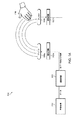
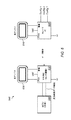
図1A〜図1C−例示的近接感知システム
図1Aは、一組の実施形態による、例示的近接感知システム100を図示する。近接感知システム100は、種々の用途において使用するために好適であり得る。例えば、近接感知システム100は、モバイルデバイス(例えば、携帯電話またはスマートフォン)、ポータブルメディアプレーヤ、電子リーダ(例えば、KindleまたはNook)、タブレット、ラップトップ、またはデスクトップコンピュータシステム、情報キオスク、自動制御パネル、あるいはユーザの近接ジェスチャを検出および解釈する能力を実装することが望ましい種々の他のシステムのいずれかにおいて、使用するために好適であり得る。
1A-1C-Exemplary Proximity Sensing System FIG. 1A illustrates an exemplary
示されるように、システム100は、複数の感知回路102a−b(本明細書では、「近接感知回路」とも称される)を含んでもよく、それぞれ、(例えば、それぞれのアンテナ104a−bを使用して)電磁信号を送信および受信することが可能であり得る。1つのセンサによって発生させられる電磁信号は、発生センサの近傍に電磁場を形成し得る。相互のセンサは、例えば、信号強度を測定することによって、電磁場を監視可能であってもよい。物体(ユーザの手106等)が、電磁場を妨害する場合、これは、例えば、電磁場を監視し得る任意のセンサによって測定される電磁場の信号強度に影響を及ぼす。
As shown, the
一組の実施形態では、感知回路102は、別のセンサによって発生させられる電磁場の変動を検出することによって、ユーザ入力を受信するように構成された1つ以上の容量感知入力部を含んでもよい。例えば、容量感知入力部は、励起に応じて、1つ以上のキャパシタを形成するように構成された伝導性材料(伝導性銅トレース等)を含んでもよい。妨害(ヒトの指または他の伝導性入力機構の近接等)によって生じる電場の強度の変動(例えば、静電容量の変動)が、測定され、かつ/または調整回路108等の別のシステム要素に送信されてもよい。他の電磁場強度/妨害感知技法もまた、可能であり、近接感知入力部の実装の詳細における多数の変形例も、可能であり得、本開示の範囲内とみなされるべきである。
In one set of embodiments, the sensing circuit 102 may include one or more capacitive sensing inputs configured to receive user input by detecting fluctuations in the electromagnetic field generated by another sensor. . For example, the capacitive sensing input may include a conductive material (such as a conductive copper trace) configured to form one or more capacitors in response to excitation. Electric field strength variations (eg, capacitance variations) caused by disturbances (such as proximity of a human finger or other conductive input mechanism) are measured and / or transmitted to another system element, such as
いくつかの実施形態では、感知回路は、電磁信号を送信または受信することを交互または交替してもよい。例えば、図1では、感知回路102aが、送信しており、感知回路102bが、受信しているが、後に、感知回路102bが、電磁信号を送信し得る(それによって、電磁場を発生させる)一方、感知回路102aが、電磁信号を受信し得る(例えば、電磁場の監視/電磁信号の信号強度の測定)。
In some embodiments, the sensing circuit may alternate or alternate in transmitting or receiving electromagnetic signals. For example, in FIG. 1,
したがって、感知回路102は、電磁場の信号強度測定に基づいて、生データを生成してもよい。交互に送信/受信することによって(可能性として、高速様式において)、異なるセンサの組み合わせ生データは、感知回路102の近傍の物体の種々の特性(例えば、根本的な存在、形状、感知回路102に対する位置、(例えば、感知回路102の数および感度に応じて、1次元、2次元、または3次元における)動作の方向、動作の速度等のうちの1つ以上)を決定するための十分な情報を含み得る。 Thus, the sensing circuit 102 may generate raw data based on signal strength measurements of the electromagnetic field. By alternately transmitting / receiving (possibly in a high-speed manner), the combined raw data of different sensors can be used to generate various characteristics (eg, underlying presence, shape, sensing circuit 102) of objects in the vicinity of the sensing circuit 102. Sufficient to determine a position relative to (eg, one or more of the direction of motion, the speed of motion, etc. in one, two, or three dimensions, depending on the number and sensitivity of sensing circuits 102). Information can be included.
しかしながら、単一の感知回路の個々の生データからそのような特性を決定することは、困難または不可能であり得る。故に、感知回路102は、調整回路108に結合されてもよい。調整回路は、例えば、整合的かつ使用可能であるデータセットを生成するために、感知回路102の調整および制御を提供し得る。例えば、調整回路108は、そのそれぞれのアンテナ104を使用して送信および受信すべきときを個々の感知回路102に示してもよい。調整回路108はまた、(例えば、スケジュールに従って、かつ/または感知回路102が、そのアンテナ104を介して受信された電磁信号に基づくデータを記録しているときに基づいて)制御された様式において、結合要素(例えば、有線通信バス)を介して、個々の感知回路102のそれぞれから生データを受信してもよい。
However, it can be difficult or impossible to determine such characteristics from individual raw data of a single sensing circuit. Thus, the sensing circuit 102 may be coupled to the
調整回路108によって生成される、調整されたデータセットは、解釈のために、解釈回路110に提供されてもよい。前述のように、感知回路102からのデータは、感知回路102の近傍の物体の種々の特性を決定するために使用可能であり得る。解釈回路110は、調整されたデータセットを分析および解釈し、感知回路102の近傍において、ユーザが1つ以上の近接ジェスチャを行なったことを決定するように構成されてもよい。
The adjusted data set generated by the
図1Bは、近接感知システム100の代替例証である。図1Bに図示されるように、感知回路102a−bは、アンテナ(「XCVR」)、遮蔽ドライバ、および調整回路108への生データ出力のためのピン接続部を有する「スレーブ」集積回路(IC)として実装されてもよい。他のピン接続部もまた、含まれてもよい。調整回路108は、示されるように、データ結合を介して、解釈回路110に結合され得る「マスタ」集積回路として実装されてもよい。次に、解釈回路110は、ホストマイクロコントローラ(MCU)として実装されてもよく、これは、実装に応じて、近接ジェスチャ解釈専用であってもよく、または他の内蔵されたシステム制御機能を提供してもよい。
FIG. 1B is an alternative illustration of
図1Cは、近接感知システム100の代替実施形態を図示する。「センサ」112のそれぞれは、図1Cに示されるように、感知回路(例えば、スレーブIC)およびアンテナの両方を含んでもよい(例えば、センサ112aは、感知回路102aおよびアンテナ104aを含み得る)ことに留意されたい。示されるように、センサ112a−bに加え、いくつかの実施形態では、付加的センサ112c−dも存在し得る。3つ以上のセンサを有するシステムは、いくつかの実施形態では、2次元または3次元ジェスチャの検出により好適であり得る。センサ112a−bは両方とも、他のセンサの全てに信号を送信する(これは、いくつかの実施形態によると、望ましくあり得る)ように示されるが、多くの実施形態では、例えば、比較的に単純な電磁場を提供するために、1度に1つのみのセンサが、送信し得ることに留意されたい。センサ112c−dは、信号を送信するように示さていれないが、これらはまた、信号を送信および受信することが可能であってもよいことに留意されたい。したがって、いくつかの実施形態では、4つのセンサ112a−dのそれぞれは、(例えば、1度に1つ)順に送信し得る一方、他の3つのセンサ(例えば、1度に1つ以上)は、信号を受信する/電磁場を監視する。
FIG. 1C illustrates an alternative embodiment of
図1Bにおけるものと同様に、図1Cの実施形態では、解釈回路110は、ホストMCUとして実装されてもよい一方、調整回路108は、マスタICとして実装されてもよい。
Similar to that in FIG. 1B, in the embodiment of FIG. 1C,
感知回路102およびアンテナ104、調整回路108、および解釈回路110が、図1A〜図1Cでは、別個の要素として示される(かつ、図1B〜図1Cにおいて特定のタイプの回路として示される)が、これらの要素の機能の一部または全部は、所望される場合、単一の回路上で組み合わせられてもよい(かつ/または示されるものと異なるタイプの回路を使用する)ことに留意されたい。例えば、感知回路102、調整回路108、および解釈回路110は、所望される場合、ハードウェア(例えば、集積回路)として、ソフトウェア(例えば、プロセッサ、およびプロセッサによって実行可能なプログラム命令を含むメモリ媒体)として、またはハードウェアおよびソフトウェアの組み合わせとして実装されてもよい。
Although sensing circuit 102 and
一組の実施形態では、近接感知回路、遮蔽ドライバ、調整回路、および解釈回路は全て、単一のフレキシブル基板上に構成されてもよい。他の実施形態では、異なる(例えば、剛な)基板あるいは(例えば、異なる回路部分に対して)複数の基板の組み合わせおよび/または異なるタイプの基板が、使用されてもよい。 In one set of embodiments, the proximity sensing circuit, shielding driver, conditioning circuit, and interpretation circuit may all be configured on a single flexible substrate. In other embodiments, different (eg, rigid) substrates or combinations of multiple substrates (eg, for different circuit portions) and / or different types of substrates may be used.
加えて、いくつかの実施形態では、システムは、システムが典型的に実装され得る電子デバイス(例えば、消費者デバイス)のタイプの多くの小型サイズに従って、比較的に薄くかつ滑らかであってもよい。例えば、一組の実施形態では、電極要素およびフレックス回路基板に対する現実的な予測は、0.25”幅×0.020”厚であり、長さは、製品固有である。任意の数の他のシステムサイズ(より大型または小型のシステムを含む)および形状も、代替として、用途に応じて、適切であり得る。 In addition, in some embodiments, the system may be relatively thin and smooth according to many small sizes of the type of electronic device (eg, consumer device) in which the system may typically be implemented. . For example, in one set of embodiments, a realistic prediction for electrode elements and flex circuit boards is 0.25 "wide x 0.020" thick and the length is product specific. Any number of other system sizes (including larger or smaller systems) and shapes may alternatively be appropriate depending on the application.
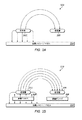
図2A〜図2B−遮蔽ドライバを有する送信器−受信器システムおよび有しない送信器−受信器システム
消費者製品における電気機械的設計制約は、近接感知ジェスチャ動作システムの提供についての課題を加える。近接電極は、多くの場合、金属ケースまたはベゼル上に直接位置し得、これは、電磁場をショートさせ、ノイズおよび静電気放電(ESD)を感知信号に注入する。これらの相反する要素から送信電極および受信電極を隔離するために、信号遮蔽ドライバが、採用されてもよい。信号遮蔽ドライバは、電極と原因金属表面との間の遮蔽層を駆動させる、送信された信号の複製を提供してもよく、したがって、送信信号は、金属に直接ショートされない。
2A-2B—Transmitter-Receiver System with and without Shielding Driver—Not Transmitter-Receiver System The electromechanical design constraints in consumer products add to the challenge of providing a proximity sensing gesture operating system. The proximity electrode can often be located directly on the metal case or bezel, which shorts the electromagnetic field and injects noise and electrostatic discharge (ESD) into the sensing signal. Signal shielding drivers may be employed to isolate the transmit and receive electrodes from these conflicting elements. The signal shielding driver may provide a duplicate of the transmitted signal that drives the shielding layer between the electrode and the cause metal surface, so that the transmitted signal is not directly shorted to the metal.
図2A〜図2Bは、遮蔽ドライバを有しない送信器−受信器システム200および遮蔽ドライバを有する送信器−受信器システム250を図示する。図2Aに示されるように、送信器202が、金属シャシー/ベゼル204または(消費者電子機器に一般的であり得るような)他の接地特徴に近接する場合、場の線は、近傍の接地に強く誘引される。その結果、受信器206近傍の電磁場は、比較的に弱くなり、これは、感知近接ジェスチャにおいて有用であるデータを生成する受信器206の能力に悪影響を及ぼし得る。
2A-2B illustrate a transmitter-
対照的に、図2Bでは、遮蔽ドライバ208は、送信された信号と同位相で駆動されるように示される。この場合、場の線(例えば、送信器202が電磁信号を送信する結果として生成された電磁場を表す)は、遮蔽ドライバが、金属シャシー/ベゼル204の方向における信号を効果的に遮蔽しているため、概して、近傍の接地から離れる方向に放出する。その結果、受信器206に向かって発射する場線の数増加によって示されるように、より強い電磁場が、受信器206に向かって放出し得る。これは、ひいては、ユーザ近接ジェスチャを検出および解釈する際のその有用性に関して、受信器206によって生成されるデータの品質を向上させ得る。一般的に、かつ/またはより具体的には、信号強度のより大きな変動が、遮蔽ドライバを有しない同様のユーザ近接ジェスチャからではなく、遮蔽ドライバを有するユーザ近接ジェスチャから生じ得るため、より強い信号強度は、データの品質向上をもたらし得る。
In contrast, in FIG. 2B, the shielding
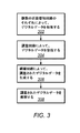
図3−近接感知データを収集する方法
図3は、近接感知データを収集する例示的方法を図示するフローチャートである。図3に示される方法は、他のシステムの中でもとりわけ、前述の図に示されるシステムのいずれかと併用され得る。種々の実施形態では、示される方法要素のうちのいくつかは、同時に行なわれ、示されるものと異なる順序で行なわれ、または省略されてもよい。付加的方法要素もまた、所望される場合、行なわれてもよい。示されるように、本方法は、以下のように動作してもよい。
FIG. 3-Method for Collecting Proximity Sensing Data FIG. 3 is a flowchart illustrating an exemplary method for collecting proximity sensing data. The method shown in FIG. 3 may be used with any of the systems shown in the previous figures, among other systems. In various embodiments, some of the illustrated method elements may be performed simultaneously, performed in a different order than shown, or omitted. Additional method elements may also be performed if desired. As shown, the method may operate as follows.
302では、デジタルデータが、複数の近接感知回路のそれぞれによって収集され得る。各近接感知回路は、電磁信号を送信および受信するように構成されたアンテナを含んでもよい。アンテナは、いくつかの実施形態によると、電磁場を発生させ/電磁場の強度を容量的に測定するように構成された単純電極であってもよい。アンテナは、所望される場合、代替として、任意の他のタイプのアンテナであってもよい。 At 302, digital data may be collected by each of a plurality of proximity sensing circuits. Each proximity sensing circuit may include an antenna configured to transmit and receive electromagnetic signals. The antenna may be a simple electrode configured to generate an electromagnetic field / capacitatively measure the strength of the electromagnetic field, according to some embodiments. The antenna may alternatively be any other type of antenna if desired.
各近接感知回路はまた、遮蔽ドライバを含んでもよい。遮蔽ドライバは、1つ以上の方向においてアンテナによって送信される信号を遮蔽するように構成されてもよい。例えば、遮蔽ドライバは、アンテナと問題の方向(例えば、金属表面または他の電磁場歪み特徴が存在する方向)との間に位置決めされてもよく、遮蔽ドライバの方向(したがって、また、問題の方向)においてアンテナによって送信される信号を遮蔽するために、アンテナと同位相で駆動されてもよい。 Each proximity sensing circuit may also include a shielding driver. The shielding driver may be configured to shield signals transmitted by the antenna in one or more directions. For example, the shield driver may be positioned between the antenna and the direction of interest (eg, the direction in which the metal surface or other electromagnetic field distortion feature is present) and the direction of the shield driver (and therefore the direction of interest). May be driven in phase with the antenna to shield the signal transmitted by the antenna.
デジタルデータは、アンテナを介して別の近接感知回路から受信された電磁信号に基づいて、収集されてもよい。いくつかの実施形態では、複数の近接感知回路は、任意の所与の時間において、複数の近接感知回路のうちの1つのみが送信している一方、1つの(または、それより多い)他の近接感知回路が、送信された信号に基づいて、デジタルデータを受信および収集するように、調整された様式において、電磁信号を送信および受信するように構成されてもよい。例えば、第1の時間において、第1の近接感知回路は、第1の電磁信号を送信し得る一方、第2の近接感知回路は、第1の電磁信号を受信し得る。次いで、第2の時間において、第2の近接感知回路は、第2の電磁信号を送信し得る一方、第1の近接感知回路は、第2の電磁信号を受信し得る。第1の近接感知回路および第2の近接感知回路は、いくつかの実施形態によると、反復様式において、送信−受信−送信等を交互してもよい。 Digital data may be collected based on electromagnetic signals received from another proximity sensing circuit via an antenna. In some embodiments, multiple proximity sensing circuits are transmitting only one (or more) others while only one of the multiple proximity sensing circuits is transmitting at any given time. The proximity sensing circuit may be configured to transmit and receive electromagnetic signals in a coordinated manner to receive and collect digital data based on the transmitted signals. For example, at a first time, a first proximity sensing circuit may transmit a first electromagnetic signal, while a second proximity sensing circuit may receive a first electromagnetic signal. Then, at a second time, the second proximity sensing circuit may transmit a second electromagnetic signal, while the first proximity sensing circuit may receive the second electromagnetic signal. The first proximity sensing circuit and the second proximity sensing circuit may alternate between transmit-receive-transmit, etc. in a repetitive manner, according to some embodiments.
いくつかの実施形態では、受信された電磁信号は、1つ以上のユーザ近接ジェスチャによって変更されてもよい。例えば、ユーザが、近接感知回路に近接してジェスチャを行なう場合、ジェスチャは、近接感知回路のうちの1つによって発生させられた電磁場を変更または妨害し得る。その時間にデータを収集している近接感知回路において受信された信号強度は、故に、影響を受け得る。 In some embodiments, the received electromagnetic signal may be modified by one or more user proximity gestures. For example, if the user makes a gesture in proximity to the proximity sensing circuit, the gesture may change or disturb the electromagnetic field generated by one of the proximity sensing circuits. The signal strength received at the proximity sensing circuit collecting data at that time can therefore be affected.
前述のように、多くの実施形態では、本方法は、典型的には、潜在的に非常に敏感な技術でありうるものに不利な環境を提供し得る消費者電子デバイスによって行なわれてもよい。例えば、容量性タッチセンサに対する典型的な静電容量変化は、約100fFであるが、非接触近接センサは、5fFの静電容量変化のみ認め得る。伝導および放射ノイズスペクトルは、WiFi、GSM(登録商標)、およびスイッチング電源からの信号でいっぱいであり、これらの干渉信号は、多くの場合、その他のパーソナルデバイスの持ち運び可能な性質により、わずか数センチメートルの距離において、ユーザによって印加される。信号ルーティングおよびノイズフィルタリングが、情報処理によって扱われなければならない。遮蔽を伴わない場合、アナログ信号を通信することは、実行不可能となり得る一方、通信線の遮蔽は、望ましくない費用を呈し得る。本理由から、信号データが、近接感知回路において、デジタル形態で収集され、またはデジタル形態に変換されることが望ましくあり得る。 As noted above, in many embodiments, the method may typically be performed by a consumer electronic device that may provide an adverse environment for what could potentially be a very sensitive technology. . For example, a typical capacitance change for a capacitive touch sensor is about 100 fF, whereas a non-contact proximity sensor can only see a capacitance change of 5 fF. Conducted and radiated noise spectra are full of signals from WiFi, GSM®, and switching power supplies, and these interfering signals are often only a few centimeters depending on the portable nature of other personal devices. Applied by the user at a distance of meters. Signal routing and noise filtering must be handled by information processing. Without shielding, communicating analog signals can be infeasible, while shielding a communication line can present an undesirable cost. For this reason, it may be desirable for signal data to be collected or converted to digital form in proximity sensing circuitry.
当業者によって認識されるように、異なるジェスチャ(異なる場所において行なわれる類似ジェスチャを含む)は、電磁場に異なる影響を及ぼし得る。いくつかの実施形態では、近接感知要素は、複数の近接感知回路が、単一のユーザ近接ジェスチャの間、信号強度データを収集し得るように十分に高速でデータ収集を交互させてもよい(および/または複数の近接感知要素は、例えば、3つ以上の近接感知要素を有するシステムにおいて、同時に、データを収集してもよい)。経時的および異なる場所(例えば、近接感知回路の異なる場所)における信号強度の差異は、近接感知回路によって収集されるデジタルデータ内に収集されてもよい。 As recognized by those skilled in the art, different gestures (including similar gestures performed at different locations) can have different effects on the electromagnetic field. In some embodiments, the proximity sensing element may alternate data collection fast enough so that multiple proximity sensing circuits can collect signal strength data during a single user proximity gesture ( And / or multiple proximity sensing elements may collect data simultaneously, eg, in a system having more than two proximity sensing elements). Differences in signal strength over time and at different locations (eg, different locations of the proximity sensing circuit) may be collected in digital data collected by the proximity sensing circuit.
304では、デジタルデータは、調整回路によって受信されてもよい。デジタルデータは、結合要素を介して、複数の近接感知回路のそれぞれから受信されてもよい。一組の実施形態では、各近接感知回路は、単一ワイヤ通信バスによって、調整回路に結合されてもよい。他のタイプの結合要素もまた、可能である。 At 304, the digital data may be received by the adjustment circuit. Digital data may be received from each of the plurality of proximity sensing circuits via the coupling element. In one set of embodiments, each proximity sensing circuit may be coupled to the conditioning circuit by a single wire communication bus. Other types of coupling elements are also possible.
一組の実施形態では、結合は、一方向性データ結合であってもよい。言い換えると、結合は、データが、一方向に、例えば、近接感知回路から調整回路に送信され得るように構成されてもよい。これは、コスト節約および/または空間節約特徴として望ましくあり得(例えば、いくつかの実施形態では、単一ワイヤインターフェースが使用されてもよい)、かつ、いくつかの実施形態では、デジタルオーバヘッドを低減させ得る。一組の実施形態によると、(電源がオンであるとき)100kbpsシリアルデータストリームを送信可能な一方向性データバスが、使用されてもよい。他の(例えば、より高いまたは低い)データレートが、異なる桁数のデータレートを含め、代替として、所望される場合、使用されてもよい。 In one set of embodiments, the combination may be a unidirectional data combination. In other words, the coupling may be configured such that data can be transmitted in one direction, eg, from the proximity sensing circuit to the conditioning circuit. This may be desirable as a cost saving and / or space saving feature (eg, in some embodiments a single wire interface may be used) and in some embodiments reduces digital overhead. Can be. According to one set of embodiments, a unidirectional data bus capable of transmitting a 100 kbps serial data stream (when powered on) may be used. Other (eg, higher or lower) data rates may alternatively be used if desired, including different digit data rates.
データ結合の一方向性性質は、調整回路の一部上の制御の全要素を除外しなくてもよいことに留意されたい。例えば、いくつかの実施形態によると、調整回路制御式電力管理を実装する通信バスが、使用されてもよい。言い換えると、通信バスは、スレーブからホストへのみのデータの通信のために構成されてもよい一方、ホストは、通信バスが電源を入れられるか、切られるかを制御するように構成されてもよい。電力管理能力は、特に、本方法を実装するシステムが、多くの消費者電子デバイスに当然一般的であるバッテリ給電である実施形態において、重要であり得る。調整回路および/または解釈回路は、センサのデューティサイクルを効率的に管理し、したがって、無駄なエネルギーがないように構成されてもよい。 Note that the unidirectional nature of the data combination may not exclude all elements of control on a portion of the regulation circuit. For example, according to some embodiments, a communication bus that implements regulated circuit controlled power management may be used. In other words, the communication bus may be configured for data communication only from the slave to the host, while the host may be configured to control whether the communication bus is turned on or off. Good. Power management capability can be important, particularly in embodiments where the system implementing the method is battery powered, which is naturally common to many consumer electronic devices. The conditioning circuit and / or interpretation circuit may be configured to efficiently manage the duty cycle of the sensor and thus free from wasted energy.
一方向性データ結合は、いくつかの実施形態では、前述の理由から望ましくあり得るが、他の実施形態では、(双方向通信のために構成される結合要素/通信バスを使用する)双方向通信が、望ましくあり得る。例えば、いくつかの実施形態では、双方向通信が望ましくあり得、それによって、調整回路が、例えば、近接感知回路を再較正するための構成情報、および単にデータ接続の電源をオン/オフにするより高いレベルのセンサ調整を提供し得る。 Unidirectional data coupling may be desirable in some embodiments for the reasons described above, while in other embodiments it is bidirectional (using a coupling element / communication bus configured for bidirectional communication). Communication may be desirable. For example, in some embodiments, two-way communication may be desirable so that the conditioning circuit can turn on / off power for configuration information, for example, to recalibrate the proximity sensing circuit, and simply the data connection A higher level of sensor adjustment may be provided.
306では、調整されたデジタルデータは、調整回路によって生成されてもよい。調整されたデジタルデータは、複数の近接感知回路のそれぞれからのデジタルデータを含んでもよい。調整されたデジタルデータは、ユーザが、特に、比較的にノイズを伴う環境において、1つ以上のユーザ近接ジェスチャを行なったことを決定する際に使用するために構成された同期されたリアルタイムセンサデータを含んでもよい。 At 306, the adjusted digital data may be generated by an adjustment circuit. The adjusted digital data may include digital data from each of the plurality of proximity sensing circuits. The conditioned digital data is synchronized real-time sensor data configured for use by a user in determining that one or more user proximity gestures have been made, particularly in a relatively noisy environment. May be included.
調整回路は、センサ動作を多重化するというタスクが課され得る。言い換えると、調整回路は、どの近接感知回路が、任意の所与の時間において、データを送信し、どの近接感知回路(単数または複数)が、データを収集するかを制御してもよい。いくつかの実施形態では、調整回路は、近接感知要素によって行なわれるタスクが、規則的反復間隔において行なわれるように、規則的スケジュールに従って、近接感知回路を調整させてもよい。調整回路は、近接感知回路への電力の制御(例えば、上記に説明された一方向性データバスを通して)および/または構成メッセージ(例えば、代替として、上記に説明された双方向データバスを通して)を介して、近接感知回路を制御するように構成されてもよい。調整回路はまた、ホスト(例えば、解釈回路)によって提供されるポリシーに基づいて、センサ電力管理を行なってもよい。いくつかの実施形態では、近接感知回路は、手動制御、例えば、ピンストラッピングによって、部分的または全体的に構成されてもよい。 The conditioning circuit may be tasked with multiplexing the sensor operation. In other words, the conditioning circuit may control which proximity sensing circuit transmits data at any given time and which proximity sensing circuit (s) collects data. In some embodiments, the adjustment circuit may cause the proximity sensing circuit to adjust according to a regular schedule such that tasks performed by the proximity sensing element are performed at regular repeating intervals. The conditioning circuit provides control of power to the proximity sensing circuit (eg, through the unidirectional data bus described above) and / or configuration messages (eg, alternatively through the bidirectional data bus described above). Via the proximity sensing circuit. The conditioning circuit may also perform sensor power management based on policies provided by the host (eg, interpretation circuit). In some embodiments, the proximity sensing circuit may be partially or fully configured by manual control, eg, pin strapping.
調整回路は、データをセンサから収集し、同期された一組のデータを解釈回路(例えば、ホスト)に送達してもよい。一組の実施形態によると、調整回路は、100Hzの更新レートにおいて、同期されたデータを解釈回路に通信してもよい。任意の他の更新レートが、代替として、所望される場合、使用されてもよい。I2C等の汎用通信バスまたは種々の他の通信バスのいずれかが、データおよび構成のために、レジスタベースのインターフェースを提供するために使用されてもよい。 The conditioning circuit may collect data from the sensor and deliver a synchronized set of data to an interpretation circuit (eg, a host). According to one set of embodiments, the conditioning circuit may communicate the synchronized data to the interpretation circuit at an update rate of 100 Hz. Any other update rate may alternatively be used if desired. Any of a general purpose communication bus such as I 2 C or various other communication buses may be used to provide a register based interface for data and configuration.
308では、調整されたデジタルデータが、解釈されてもよい。調整されたデジタルデータは、前述のように、いくつかの実施形態に従ったホストコントローラであり得る解釈回路によって解釈されてもよい。解釈回路は、例えば、調整回路の更新レートに従って、定期的データ通信を扱うように構成されてもよい。一組の実施形態によると、データ転送は、例えば、プロトコルオーバーヘッドおよび所望される場合に構成され得るシングル対ブロックモード転送に応じて、約10〜40Kbpsで行なわれてもよい。例えば、一組の実施形態では、約50〜100ビットのセンサ情報が、100Hz更新レートで受信されてもよい。これは、いくつかの実施形態では、50〜100msの期間で決定(例えば、ジェスチャ解釈)が行なわれることを可能にし得る。他の決定時間フレームもまた、可能である。異なる量のセンサ情報を含む、他のデータ転送レートも、代替として、所望される場合、使用されてもよい。いくつかの実施形態では、解釈回路はまた、記憶のための専用RAMを含んでもよい。例えば、一組の実施形態では、解釈回路は、任意の所与の時間において、(例えば、生ジェスチャデータに値する1〜2秒を表す)100〜200のデータセットを記憶するように構成され、利用されてもよい。種々の処理負荷およびプログラムメモリサイズのいずれかが、例えば、他の所望の実装詳細に応じて、所望される場合、使用されてもよい。 At 308, the adjusted digital data may be interpreted. The adjusted digital data may be interpreted by an interpretation circuit, which may be a host controller according to some embodiments, as described above. The interpretation circuit may be configured to handle periodic data communication, for example, according to the update rate of the adjustment circuit. According to one set of embodiments, data transfer may occur at about 10-40 Kbps, depending on, for example, protocol overhead and single-to-block mode transfer that may be configured as desired. For example, in one set of embodiments, approximately 50-100 bits of sensor information may be received at a 100 Hz update rate. This may allow the determination (eg, gesture interpretation) to be made in a period of 50-100 ms in some embodiments. Other decision time frames are also possible. Other data transfer rates, including different amounts of sensor information, may alternatively be used if desired. In some embodiments, the interpretation circuit may also include a dedicated RAM for storage. For example, in one set of embodiments, the interpreter circuit is configured to store 100-200 data sets (eg, representing 1-2 seconds worth of raw gesture data) at any given time; It may be used. Any of various processing loads and program memory sizes may be used if desired, eg, depending on other desired implementation details.
調整されたデジタルデータの解釈は、ユーザが1つ以上のユーザ近接ジェスチャを行なったことを決定することを含んでもよい。例えば、一組の実施形態によると、アルゴリズムが、調整されたデジタルデータに基づいて、ユーザ制御された物体によって行なわれるジェスチャを識別するために十分な精度を有する近接感知回路のうちの1つ以上に近接するユーザ制御された物体の方向、速度、サイズ、および/または場所のうちの1つ以上を決定するために使用されてもよい。ユーザ挙動は、紛らわしくあり得るが、広範囲のジェスチャ速度および信号強度が容認され得ると同時に、エラーはまた、最小限にされるべきである。 Interpreting the adjusted digital data may include determining that the user has made one or more user proximity gestures. For example, according to one set of embodiments, one or more of proximity sensing circuits with sufficient accuracy for the algorithm to identify a gesture made by a user-controlled object based on the adjusted digital data. May be used to determine one or more of the direction, velocity, size, and / or location of user-controlled objects proximate to. User behavior can be confusing, but errors should also be minimized while a wide range of gesture speeds and signal strengths can be tolerated.
故に、解釈回路によって使用されるアルゴリズムはさらに、ジェスチャとして意図されない動作の誤解釈を回避するように構成されてもよい。例えば、例えば、虫のサイズおよび/または虫の動きの質から生じる調整されたデジタルデータの差異に基づいて、ユーザが行なったジェスチャとして、近接感知回路の近傍を飛んでいる虫を誤解釈することを回避するように、調整されたデジタルデータは、十分な情報を含み得、解釈アルゴリズムは、十分に高度であり得る。解釈アルゴリズム(および、解釈が基づく調整されたデジタルデータ)はまた、同様に、ユーザによって行なわれる意図されないジェスチャを含む、他の意図されないジェスチャの誤解釈を回避するように構成されてもよい。 Thus, the algorithm used by the interpreter circuit may be further configured to avoid misinterpretation of actions that are not intended as gestures. For example, misinterpreting a bug flying in the vicinity of a proximity sensing circuit as a gesture made by a user, for example, based on a difference in adjusted digital data resulting from the size of the bug and / or the quality of the movement of the bug The adjusted digital data may contain sufficient information and the interpretation algorithm may be sufficiently sophisticated. The interpretation algorithm (and the adjusted digital data on which the interpretation is based) may also be configured to avoid misinterpretation of other unintended gestures, including unintended gestures made by the user as well.
いくつかの実施形態では、調整回路および解釈回路は、(例えば、前述のように、その間の通信のために、I2Cまたは他のバスを使用して)別個の回路として実装されてもよいが、他の実施形態では、調整回路および解釈回路は、単一の回路として実装されてもよいことに留意されたい。例えば、ジェスチャ分析およびリアルタイムセンサ制御のために組み合わせられたコントローラは、より低いコスト、通信バスの排除、ならびに開発中および生産の際の順応性を含む、多くの利点を有し得る。例えば、調整回路のためのMCUの使用は、開発段階の際、非常に望ましい順応性を提供し得る。代替として、または加えて(例えば、後の開発段階において)、組み合わせ部品が、例えば、コストおよびエネルギー消費の削減ならびに効率増加のために、ステートマシンに付され得る(但し、潜在的に、順応性を犠牲にする)。 In some embodiments, the coordination and interpretation circuits may be implemented as separate circuits (eg, using I 2 C or other buses for communication therebetween as described above). However, it should be noted that in other embodiments, the adjustment circuit and the interpretation circuit may be implemented as a single circuit. For example, a controller combined for gesture analysis and real-time sensor control can have many advantages, including lower cost, elimination of communication buses, and flexibility during development and production. For example, the use of an MCU for the conditioning circuit can provide very desirable flexibility during the development phase. Alternatively or additionally (eg, in later development stages), combined components can be attached to a state machine (but potentially adaptable, for example, to reduce cost and energy consumption and increase efficiency) Sacrificing).
代替として、分析部分は、別のホストコントローラ(例えば、ノートブックキーボードコントローラまたはUSBカードリーダコントローラ等の既存のMCU)に移動され得、したがって、ファームウェアは、システムの残りの部分に緊密に結合され、1つの場所のみで、開発および維持されることができる。この場合、リアルタイムセンサ制御(例えば、調整回路)のみが、IC内に残されてもよく、いくつかの実施形態では、レジスタ構成可能特定用途向け標準品(ASSP)として取り扱われ得る。 Alternatively, the analysis portion can be moved to another host controller (e.g., an existing MCU such as a notebook keyboard controller or USB card reader controller), so that the firmware is tightly coupled to the rest of the system, It can be developed and maintained in only one place. In this case, only real-time sensor control (eg, regulation circuitry) may be left in the IC, and in some embodiments may be treated as a register configurable application specific standard (ASSP).
図4−タイミング図
図4は、一組の実施形態による、近接感知回路から調整回路へのデータ転送を図示するタイミング図400である。示される実施形態では、データ転送は、ホスト制御式電力管理を用いて、一方向性通信バスを使用して行なわれてもよい。センサが、測定可能にされると(例えば、通信バスの電源をオンにすることによって)、内部ブロックが起動され、測定を行い、100kbpsシリアルデータストリームを出力し得る。これは、データラインを引き下げることによって(この時、センサの電源が切られ得る)、ホストがセンサを無効にするまで持続し得る。
FIG. 4—Timing Diagram FIG. 4 is a timing diagram 400 illustrating data transfer from proximity sensing circuitry to a conditioning circuit, according to one set of embodiments. In the illustrated embodiment, data transfer may be performed using a one-way communication bus with host-controlled power management. When the sensor is enabled for measurement (e.g., by turning on the communication bus), the internal block may be activated to take a measurement and output a 100 kbps serial data stream. This can last until the host disables the sensor by pulling down the data line (at which time the sensor can be powered off).
示されるように、通信バスは、一組の実施形態では、内部100KHzクロックに従って動作し得る。データ送信は、データ自体の周囲に最小のオーバーヘッド(例えば、数同期ビット、センサ番号およびタイプを識別するための数ビット、および停止ビット)を含み得る。 As shown, the communication bus may operate according to an internal 100 KHz clock in one set of embodiments. The data transmission may include minimal overhead around the data itself (eg, a few synchronization bits, a few bits to identify the sensor number and type, and a stop bit).
図4に示されるタイミング図400によって図示される例示的システムが、近接感知回路と調整回路との間の通信のための可能性として考えられるシステムの1つを表すが、他のシステムもまた、可能であり、したがって、図4およびその説明は、本開示を全体として限定するものと見なされるべきではない。 While the exemplary system illustrated by the timing diagram 400 shown in FIG. 4 represents one possible system for communication between proximity sensing circuitry and coordination circuitry, other systems may also As such, FIG. 4 and its description should not be regarded as limiting the present disclosure as a whole.
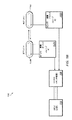
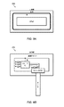
図5−例示的システム略図
図5は、2つの近接感知回路を含む、1つの可能性として考えられるシステム500を図示するブロック図である。図5の例示的システム500では、近接感知回路はそれぞれ、8ピン集積回路(IC)であり得る。マスタIC502は、調整回路および近接感知回路の両方として作用してもよい一方、スレーブIC504は、近接感知回路としてのみ機能してもよい。スレーブIC504は、データ結合、例えば、種々の実施形態による、本開示のいずれかに説明されるような一方向性または双方向性通信バスを介して、マスタIC502に結合されてもよい。マスタIC502は、データ結合を介して、スレーブIC504データを受信し、アクティブデューティサイクルによって、スレーブIC504の電力を管理してもよく、衝突を回避するために、センサ信号を順序付けてもよい。
FIG. 5—Example System Schematic FIG. 5 is a block diagram illustrating one
マスタIC502はまた、解釈回路として作用し得るホストマイクロコントローラ(MCU)506に結合されてもよい。マスタIC502およびホストMCU506は、双方向性データ結合(例えば、双方向通信バス)を使用して結合されてもよく、双方向性データ結合は、マスタIC502が調整されたセンサデータをホストMCU506に通信することと、ホストMCU506が構成情報をマスタIC502に通信することとの両方に使用され得る。示されるように、一組の実施形態では、マスタIC502とホストMCU506との間のデータバスは、3つのピンを利用してもよい一方、マスタIC502とスレーブIC504との間のバスは、単一のピンを利用してもよい。マスタ502およびスレーブ504ICはそれぞれ、アンテナ接続(例えば、近接感知要素)および遮蔽ドライバのために構成されたピンを含んでもよい。マスタ502およびスレーブ504ICのそれぞれはまた、電力供給源ピン(例えば、Vddおよび接地)を含んでもよい。スレーブIC504はまた、手動ピンストラッピング(例えば、ICパラメータ/構成設定を手動で構成する)のために、3つの構成ピンを含んでもよい。
The
示されるように、アンテナ接続は、左アンテナ508および右アンテナ510を含んでもよい。図5に示される2センサシステムは、1次元ジェスチャ検出(例えば、左右平面におけるジェスチャ)に好適であり得る。左右配向が、いくつかの用途に適切であり得るが、他の配向(例えば、上下、斜方向、または別の配向)も、他の用途に適切であり得、また、使用されてもよい。
As shown, the antenna connection may include a
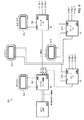
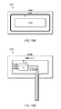
図6−例示的システム略図
図6は、4つの近接感知回路を含む、1つの可能性として考えられるシステム600を図示するブロック図である。示されるように、図6のシステム600は、実質的に、図5のシステム500のアーキテクチャに類似し得るが、明らかな例外として、システムは、2つの付加的スレーブIC604b−cを含み、マスタIC602は、2つの付加的スレーブIC604b−cに結合するデータ結合のための2つの付加的ピンを含む。
FIG. 6--Exemplary System Schematic FIG. 6 is a block diagram illustrating one
したがって、図6の例示的システム600では、マスタIC602は、10ピン集積回路であり得る一方、スレーブIC604a−cはそれぞれ、8ピン集積回路であり得る。図5のシステムにおけるように、マスタIC602は、調整回路および近接感知回路の両方として作用してもよい一方、スレーブIC604a−cは、近接感知回路としてのみ、機能してもよい。スレーブIC604a−cは、通信バス、例えば、種々の実施形態による、本開示のいずれかに説明されるような一方向性または双方向性通信バスを介して、マスタIC602に結合されてもよい。マスタIC602は、通信バスを介して、スレーブIC604a−cデータを受信し、アクティブデューティサイクルを介して、スレーブIC604a−c電力を管理してもよく、衝突を回避するために、センサ信号を順序付けてもよい。
Thus, in the
図5のシステム500と同様に、マスタIC602はまた、解釈回路として作用し得る、ホストマイクロコントローラ(MCU)606に結合されてもよい。マスタIC602およびホストMCU606は、双方向性データ結合(例えば、双方向通信バス)を使用して結合されてもよく、双方向性データ結合は、マスタIC602が調整されたセンサデータをホストMCU606に通信することと、ホストMCU606が構成情報をマスタIC602に通信することとの両方に使用され得る。示されるように、一組の実施形態では、マスタIC602とホストMCU606との間のデータバスは、3つのピンを利用し得る一方、マスタIC602とそれぞれのスレーブIC604との間の各バスは、単一のピンを利用してもよい。マスタIC602およびスレーブ604a−cICはそれぞれ、アンテナ接続(例えば、近接感知要素)および遮蔽ドライバのために構成されたピンを含んでもよい。マスタIC602およびスレーブ604a−cICのそれぞれはまた、電力供給源ピン(例えば、Vddおよび接地)を含んでもよい。スレーブIC604a−cはまた、手動ピンストラッピング(例えば、ICパラメータ/構成設定を手動で構成する)ために、3つの構成ピンを含んでもよい。
Similar to
4つの近接感知回路を有する図6のシステム600は、2次元または3次元で行なわれたジェスチャを検出および解釈するために適切であり得る。例えば、アンテナ608、610、612、614は、左右および上下の両方の向きに向けられてもよく、アンテナ608、610、612、614によって収集されたデータに基づいて、奥行次元における近接ジェスチャ動作器具の動作が、左右方向および上下方向における近接ジェスチャ動作器具の動作と同様に解釈され得るように十分に敏感であり得る。
The
図5〜図6に示される近接感知システムは、2つの可能な近接感知システムを表すが、当業者は、任意の数の他のシステム構成(異なる構成要素および/または異なる方法で実装された類似構成要素を含む)が、所望される場合使用されてもよく、図5〜図6に関して示され、説明される近接感知システムが、本開示を全体として限定するものと見なされるべきではないことを認識することに留意されたい。 Although the proximity sensing systems shown in FIGS. 5-6 represent two possible proximity sensing systems, those skilled in the art will recognize any number of other system configurations (different components and / or similar implementations implemented in different ways). (Including components) may be used if desired and the proximity sensing system shown and described with respect to FIGS. 5-6 should not be considered as limiting the present disclosure as a whole. Note that you recognize.
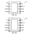
図7〜図8−IC略図
図7〜図8は、図5および図6に図示されるもののようなスレーブICおよびマスタICのための可能性として考えられるピン構成を図示する。図7Aは、単一スレーブICを制御するように構成されたマスタIC700のための可能性として考えられるピン構成を図示する一方、図7Bは、3つのスレーブICを制御するように構成されたマスタIC750のための可能性として考えられるピン構成を図示する。
FIGS. 7-8-IC Schematic FIGS. 7-8 illustrate possible pin configurations for slave and master ICs such as those illustrated in FIGS. FIG. 7A illustrates a possible pin configuration for a
示されるように、マスタIC700およびマスタIC750は両方とも、電力供給源ピンVdd(ピン1)およびGND(ピン2)を含んでもよい。ピン3−5は、マスタIC700(または、750)と解釈回路(例えば、ホストMCU)との間で通信するために使用される、通信バス専用であってもよい。マスタIC700は、その唯一のスレーブICと通信するための単一ピン(ピン6)を含んでもよい一方、マスタIC750は、その3つのスレーブICと通信するための3つのピン(ピン6−8)を含んでもよい。マスタIC700は、その最終の2つのピン(ピン7−8)として、遮蔽ドライバ接続および近接感知要素(例えば、アンテナ/電極)接続を含んでもよい。マスタIC750はまた、その最終の2つのピン(ピン9−10)として、遮蔽ドライバ接続および近接感知要素(例えば、アンテナ/電極)接続を含んでもよい。
As shown, both
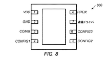
図8は、図7A〜図7Bに示されるマスタIC700またはマスタIC750によって制御され得るようなスレーブIC800のための可能性として考えられるピン構成を図示する。示されるように、スレーブIC800は、電力供給源ピンVdd(ピン1)およびGND(ピン2)を含んでもよい。スレーブIC800は、そのマスタICと通信するための単一ピン(ピン3)を含んでもよい。ピン4−6は、異なるピン−ストラッピング構成オプション専用であってもよい。例えば、ピン4−6のピンストラッピングを介して(例えば、異なるハードコードされた組み合わせに)調節され得る、パラメータは、感度/利得、平均化/フィルタリング、デジタル特徴(例えば、負デルタカウント、ノイズ遮断、最大持続時間等)および再較正を含み得る。スレーブIC800はまた、その最終の2つのピン(ピン9−10)として、遮蔽ドライバ接続および近接感知要素(例えば、アンテナ/電極)接続を含んでもよい。
FIG. 8 illustrates a possible pin configuration for a
図7〜図8に図示されるピン構成は、マスタICおよびスレーブICの一組の可能なピン構成を表すが、任意の数の他の構成も、所望される場合、使用されてもよく、図7−8に関して示され、説明された構成は、本開示を全体として限定するものと見なされるべきではないことに留意されたい。 The pin configurations illustrated in FIGS. 7-8 represent a set of possible pin configurations for a master IC and a slave IC, but any number of other configurations may be used if desired, Note that the configurations shown and described with respect to FIGS. 7-8 should not be construed as limiting the present disclosure as a whole.
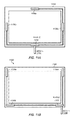
図9〜図10−例示的PCBおよびフレックス回路実装
図9A〜図9Bは、一組の実施形態による、近接感知回路を実装する、プリント回路基板(PCB)900の上部側および底部側を図示する。図10A〜図10Bは、一組の実施形態による、近接感知回路を実装するフレックス回路1000の上部側および底部側を図示する。
FIGS. 9-10—Exemplary PCB and Flex Circuit Implementation FIGS. 9A-9B illustrate the top and bottom sides of a printed circuit board (PCB) 900 implementing proximity sensing circuitry, according to one set of embodiments. . 10A-10B illustrate the top and bottom sides of a
示されるように、近接感知回路の実装は、PCBおよびフレックス回路実装の両方に類似であり得る(例えば、スレーブIC、遮蔽ドライバ、アンテナ、モードピン、ならびに電力供給源および通信バス接続を含む)。主な差異は、PCB実装では、ケーブルを使用して他のシステム要素(例えば、電力供給源および調整回路)に結合され得る3ピンコネクタを使用することにあり得る。対照的に、フレックス回路のフレキシブル基板は、電力供給源および通信バス接続が、恒久的結合を介して、他のシステム要素に直接続くことを可能にし得る。これは、いくつかの実施形態では、PCB実装に示される3ピンコネクタ等のコネクタを排除するために、望ましくあり得る。 As shown, proximity sensing circuit implementations may be similar to both PCB and flex circuit implementations (including, for example, slave ICs, shielded drivers, antennas, mode pins, and power supply and communication bus connections). The main difference may be in the PCB implementation, using a 3-pin connector that can be coupled to other system elements (eg, power supply and conditioning circuitry) using cables. In contrast, a flexible circuit board of a flex circuit may allow power supply and communication bus connections to continue directly to other system elements via permanent coupling. This may be desirable in some embodiments to eliminate connectors such as the 3-pin connector shown in the PCB implementation.
図9〜図10に図示されるPCBおよびフレックス回路実装は、近接感知回路の2つの可能な実装を表すが、任意の数の他の実装が、所望される場合、使用されてもよく、図9〜図10に関して示され、説明された実装は、本開示を全体として限定するものと見なされるべきではないことに留意されたい。 The PCB and flex circuit implementations illustrated in FIGS. 9-10 represent two possible implementations of proximity sensing circuitry, but any number of other implementations may be used if desired, It should be noted that the implementations shown and described with respect to FIGS. 9-10 should not be considered as limiting the present disclosure as a whole.
図11A〜図11B−ベゼル実装
図11A〜図11Bは、例えば、近接感知システムが実装される電子デバイスの縁に沿った、ベゼル上の近接感知回路の可能な配列を図示する。
11A-11B—Bezel Implementation FIGS. 11A-11B illustrate possible arrangements of proximity sensing circuitry on the bezel, for example, along the edge of an electronic device in which the proximity sensing system is implemented.
図11Aに示されるように、1つの可能性として考えられる配列は、ベゼル1100の上縁/下縁/左縁/右縁のそれぞれの中心に置かれた近接感知回路を含む。示されるように、マスタモジュール1102(例えば、マスタICを含む)は、下縁に沿って設置されてもよく、ホストMCU1104に結合されてもよい。マスタモジュール1102は、ベゼル1100の上縁、左縁、および右縁のそれぞれの中心に位置し得るスレーブIC1106a−cのそれぞれへの接続を含んでもよい。本配列は、センサ配置に望ましくあり得(例えば、ジェスチャ解釈アルゴリズムに応じて)、所望される場合、使用されてもよいが、本設計は、フレックス回路を使用して実装するのは困難であり得、したがって、図11Bに示されるような代替配列が、いくつかの実施形態では、より望ましくあり得る。
As shown in FIG. 11A, one possible arrangement includes proximity sensing circuitry centered on the top edge / bottom edge / left edge / right edge of the
図11Bに示される配列では、近接感知回路は、ベゼル1100の角のそれぞれに位置してもよい。マスタモジュール1102は、右下角に沿って設置されてもよく、ホストMCU1104に結合されてもよい。マスタモジュール1102は、ベゼル1100の左上角、左下角、および右上角のそれぞれに位置し得るスレーブIC1106a−cのそれぞれへの接続を含んでもよい。本配列は、「L」形状のパターンが、フレックス回路シート上において、比較的に容易に入れ子にされ得るため、いくつかの実施形態では、より望ましくあり得る。加えて、ケーブルアクセスは、多くの場合、ベゼルの角にあり得る。センサの角位置はまた、例えば、そのような実施形態では、上/下および右/左に対して冗長な情報を提供可能であり得るため、望ましくあり得る(再び、ジェスチャ解釈アルゴリズムに応じて)。
In the arrangement shown in FIG. 11B, proximity sensing circuitry may be located at each corner of
図11Aおよび11Bは、長方形ベゼル上の2つの可能なセンサ配列を表すが、他のベゼル形状および(例えば、ベゼル上または他の場所における)センサ配列もまた、可能であり、用途に応じて、より望ましくあり得ることに留意されたい。故に、図11A〜図11Bに関して示され、説明された実装は、本開示を全体として限定するものと見なされるべきではない。 11A and 11B depict two possible sensor arrangements on a rectangular bezel, other bezel shapes and sensor arrangements (eg, on the bezel or elsewhere) are also possible, depending on the application, Note that it may be more desirable. Thus, the implementations shown and described with respect to FIGS. 11A-11B should not be considered as limiting the present disclosure as a whole.
前述の実施形態は、かなり詳細に説明されたが、前述の開示が完全に理解されると、多数の変形例および修正が、当業者には明白となる。以下の特許請求の範囲は、全てのそのような変形例および修正を包含するように解釈されることが意図される。 Although the foregoing embodiments have been described in considerable detail, numerous variations and modifications will become apparent to those skilled in the art once the above disclosure is fully appreciated. It is intended that the following claims be construed to include all such variations and modifications.
Claims (24)
複数の近接感知回路と調整回路とを備え、
各近接感知回路は、
第1のモードにおいて電磁信号を送信することと、第2のモードにおいて電磁信号を受信することとを行うように構成されたアンテナと、
前記第1のモードにおいて、前記アンテナによって1つ以上の方向に送信される遮蔽信号を生成するように構成された遮蔽ドライバと、
前記第2のモードに設定されている近接感知回路から前記アンテナを介して受信された電磁信号に基づいてデジタルデータを収集するように構成された論理であって、前記受信された電磁信号は、1つ以上のユーザ近接ジェスチャによって変更される、論理と
を備え、
前記調整回路は、前記複数の近接感知回路のそれぞれに結合され、前記調整回路は、論理を備え、
前記論理は、
前記複数の近接感知回路のうちの1つを前記第1のモードに設定し、前記複数の近接感知回路のうちの残りを前記第2のモードに設定することと、
前記複数の近接感知回路のそれぞれからデジタルデータを受信することと、
前記複数の近接感知回路のそれぞれから受信された前記デジタルデータから調整されたデジタルデータを生成することと
を行うように構成されており、前記調整されたデジタルデータは、前記複数の近接感知回路のそれぞれからの前記デジタルデータを含み、前記調整されたデジタルデータは、ユーザが前記1つ以上のユーザ近接ジェスチャを行なったことを決定する際に使用されるように構成されており、
前記第1のモードに設定された前記複数の近接感知回路のうちの前記1つは、前記第1のモードの間、送信器としてのみ動作し、
前記複数の近接感知回路のうちの前記残りは、前記第2のモードの間、受信器としてのみ動作し、前記第1のモードに設定された前記複数の近接感知回路のうちの前記1つによって放出された電磁場を容量結合を介して受信する、近接感知システム。 A proximity sensing system, the system comprising:
A plurality of proximity sensing circuits and adjustment circuits;
Each proximity sensing circuit
An antenna configured to perform the method comprising: transmitting electromagnetic signals, and receiving an electromagnetic signal in the second mode in the first mode,
A shielding driver configured to generate a shielding signal transmitted by the antenna in one or more directions in the first mode ;
A logic configured to collect digital data based on the electromagnetic signals received via the antenna from the proximity sensing circuit is set to the second mode, the received electromagnetic signal Logic that is modified by one or more user proximity gestures , and
Before SL adjustment circuit is coupled to each of the plurality of proximity sensing circuit, the adjusting circuit includes a logic,
The logic is
Setting one of the plurality of proximity sensing circuits to the first mode and setting the rest of the plurality of proximity sensing circuits to the second mode;
Receiving a digital data from each of the plurality of proximity sensing circuit,
Generating a digital data adjusted by the digital data received from each of the plurality of proximity sensing circuit
Is configured to perform, the adjusted digital data comprises the digital data from each of the plurality of proximity sensing circuit, a digital data to which the adjusted, the user said one or more user proximity It is configured to be used in determining that you have made a gesture ,
The one of the plurality of proximity sensing circuits set to the first mode operates only as a transmitter during the first mode;
The remainder of the plurality of proximity sensing circuits operates only as a receiver during the second mode, and by the one of the plurality of proximity sensing circuits set to the first mode. A proximity sensing system that receives an emitted electromagnetic field via capacitive coupling .
第1の時間において、第1の近接感知回路が、第1の電磁信号を送信するように構成されている一方、第2の近接感知回路が、前記第1の電磁信号を受信するように構成されており、かつ、
第2の時間において、前記第2の近接感知回路が、第2の電磁信号を送信するように構成されている一方、前記第1の近接感知回路が、前記第2の電磁信号を受信するように構成されている
ような調整された様式において、電磁信号を送信および受信するように構成されている、請求項1に記載の近接感知システム。 The plurality of proximity sensing circuits include:
At a first time, a first proximity sensing circuit is configured to transmit a first electromagnetic signal, while a second proximity sensing circuit is configured to receive the first electromagnetic signal. It has been, and,
At a second time, the second proximity sensing circuit is configured to transmit a second electromagnetic signal, while the first proximity sensing circuit receives the second electromagnetic signal. The proximity sensing system of claim 1, wherein the proximity sensing system is configured to transmit and receive electromagnetic signals in a coordinated manner.
前記論理は、
前記調整されたデジタルデータを受信することと、
前記調整されたデジタルデータを解釈することであって、前記解釈ことは、ユーザが前記1つ以上のユーザ近接ジェスチャを行なったことを決定する、ことと
を行うように構成されている、請求項1に記載の近接感知システム。 The system further comprises an interpretation circuit, the interpretation circuit comprising logic ,
The logic is
Receiving the adjusted digital data;
Interpreting the adjusted digital data, wherein the interpreting is configured to determine that a user has performed the one or more user proximity gestures. 2. The proximity sensing system according to 1.
複数の近接感知回路のそれぞれが、デジタルデータを収集することであって、各近接感知回路は、第1のモードにおいて電磁信号を送信することと、第2のモードにおいて電磁信号を受信することとを行うように構成されたアンテナと、前記第1のモードにおいて、前記アンテナによって1つ以上の方向に送信される遮蔽信号を生成するように構成された遮蔽ドライバとを備え、前記デジタルデータは、前記第2のモードに設定されている近接感知回路から前記アンテナを介して受信された電磁信号に基づいて収集され、前記受信された電磁信号は、1つ以上のユーザ近接ジェスチャによって変更される、ことと、
調整回路が、前記複数の近接感知回路のうちの1つを前記第1のモードに設定し、前記複数の近接感知回路のうちの残りを前記第2のモードに設定することと、
前記調整回路が、前記複数の近接感知回路のそれぞれからデジタルデータを受信することと、
前記調整回路が、前記複数の近接感知回路のそれぞれから受信された前記デジタルデータから調整されたデジタルデータを生成することであって、前記調整されたデジタルデータは、前記複数の近接感知回路のそれぞれからの前記デジタルデータを含み、前記調整されたデジタルデータは、ユーザが前記1つ以上のユーザ近接ジェスチャを行なったことを決定する際に使用されるように構成されている、ことと
を含み、
前記第1のモードに設定された前記複数の近接感知回路のうちの前記1つは、前記第1のモードの間、送信器としてのみ動作し、
前記複数の近接感知回路のうちの前記残りは、前記第2のモードの間、受信器としてのみ動作し、前記第1のモードに設定された前記複数の近接感知回路のうちの前記1つによって放出された電磁場を容量結合を介して受信する、方法。 Proximity sensing data collection method comprising:
Each of the plurality of proximity sensing circuit, the method comprising: collecting digital data, each proximity sensing circuit, and transmitting an electromagnetic signal in the first mode, and receiving an electromagnetic signal in the second mode An antenna configured to perform and a shielding driver configured to generate a shielding signal transmitted by the antenna in one or more directions in the first mode, the digital data comprising: is collected based on an electromagnetic signal received through the antenna from the proximity sensing circuit is set to the second mode, the received electromagnetic signal is altered by one or more user proximity gesture, And
An adjustment circuit sets one of the plurality of proximity sensing circuits to the first mode and the rest of the plurality of proximity sensing circuits to the second mode;
And said adjustment circuit receives the digital data from each of the plurality of proximity sensing circuit,
Said adjustment circuit, and generating a digital data adjusted by the digital data received from each of the plurality of proximity sensing circuit, the adjusted digital data is, each of the plurality of proximity sensing circuit wherein the digital data from the digital data to which the adjusted, the user is configured to be used in determining that an attempt was made to the one or more user proximity gesture, and containing viewed ,
The one of the plurality of proximity sensing circuits set to the first mode operates only as a transmitter during the first mode;
The remainder of the plurality of proximity sensing circuits operates only as a receiver during the second mode, and by the one of the plurality of proximity sensing circuits set to the first mode. A method of receiving an emitted electromagnetic field via capacitive coupling .
第1の近接感知回路が第1の電磁信号を送信することと、
第2の近接感知回路が前記第1の電磁信号を受信することと、
第2の時間において、
前記第2の近接感知回路が第2の電磁信号を送信することと、
前記第1の近接感知回路が前記第2の電磁信号を受信することと
をさらに含む、請求項13に記載の方法。 In the first time,
Transmitting a first electromagnetic signal by a first proximity sensing circuit;
Receiving a first electromagnetic signal by a second proximity sensing circuit;
In the second time,
The second proximity sensing circuit transmits a second electromagnetic signal;
14. The method of claim 13 , further comprising: the first proximity sensing circuit receiving the second electromagnetic signal.
前記解釈回路が、前記調整されたデジタルデータを解釈することであって、前記解釈することは、ユーザが前記1つ以上のユーザ近接ジェスチャを行なったことを決定する、ことと
をさらに含む、請求項13に記載の方法。 And the interpretation circuit receives the digital data to which the adjusted,
The interpretation circuit, the method comprising interpreting the digital data to which the adjusted, to the interpretation, determines that the user performs the one or more user proximity gesture, further comprising a thing, wherein Item 14. The method according to Item 13 .
複数の近接感知回路と、前記複数の近接感知回路のそれぞれに結合された調整回路とを備え、
各近接感知回路は、
第1のモードにおいて電磁信号を送信することと、第2のモードにおいて電磁信号を受信することとを行うように構成されたアンテナと、
前記第1のモードにおいて、前記アンテナによって1つ以上の方向に送信される遮蔽信号を生成するように構成された遮蔽ドライバと、
前記第2のモードに設定されている近接感知回路から前記アンテナを介して受信された電磁信号に基づいてデジタルデータを収集するように構成された論理であって、前記受信された電磁信号は、1つ以上のユーザ近接ジェスチャによって変更される、論理と
を備え、
前記調整回路は、
前記複数の近接感知回路のうちの1つを前記第1のモードに設定し、前記複数の近接感知回路のうちの残りを前記第2のモードに設定することと、
前記複数の近接感知回路のそれぞれからデジタルデータを受信することと、
ユーザが前記1つ以上のユーザ近接ジェスチャを行なったことを決定する際に使用される情報を提供することと
を行うように構成されており、
前記第1のモードに設定された前記複数の近接感知回路のうちの前記1つは、前記第1のモードの間、送信器としてのみ動作し、
前記複数の近接感知回路のうちの前記残りは、前記第2のモードの間、受信器としてのみ動作し、前記第1のモードに設定された前記複数の近接感知回路のうちの前記1つによって放出された電磁場を容量結合を介して受信する、システム。
A proximity sensing system, the system comprising:
A plurality of proximity sensing circuits and an adjustment circuit coupled to each of the plurality of proximity sensing circuits;
Each proximity sensing circuit
An antenna configured to perform the method comprising: transmitting electromagnetic signals, and receiving an electromagnetic signal in the second mode in the first mode,
A shielding driver configured to generate a shielding signal transmitted by the antenna in one or more directions in the first mode ;
Wherein a logic configured to collect digital data from the proximity sensing circuit is set to the second mode based on the electromagnetic signal received through the antenna, the received electromagnetic signal, Logic that is modified by one or more user proximity gestures , and
The adjustment circuit includes:
Setting one of the plurality of proximity sensing circuits to the first mode and setting the rest of the plurality of proximity sensing circuits to the second mode;
Receiving digital data from each of the plurality of proximity sensing circuits ;
Providing information for use in determining that a user has made the one or more user proximity gestures ;
It is configured to perform,
The one of the plurality of proximity sensing circuits set to the first mode operates only as a transmitter during the first mode;
The remainder of the plurality of proximity sensing circuits operates only as a receiver during the second mode, and by the one of the plurality of proximity sensing circuits set to the first mode. A system for receiving an emitted electromagnetic field via capacitive coupling .
Applications Claiming Priority (3)
| Application Number | Priority Date | Filing Date | Title |
|---|---|---|---|
| US13/334,477 US9298333B2 (en) | 2011-12-22 | 2011-12-22 | Gesturing architecture using proximity sensing |
| US13/334,477 | 2011-12-22 | ||
| PCT/US2012/068867 WO2013095985A1 (en) | 2011-12-22 | 2012-12-11 | Gesturing architecture using proximity sensing |
Publications (2)
| Publication Number | Publication Date |
|---|---|
| JP2015503783A JP2015503783A (en) | 2015-02-02 |
| JP6128564B2 true JP6128564B2 (en) | 2017-05-17 |
Family
ID=47561808
Family Applications (1)
| Application Number | Title | Priority Date | Filing Date |
|---|---|---|---|
| JP2014549106A Active JP6128564B2 (en) | 2011-12-22 | 2012-12-11 | Gesture motion architecture using proximity sensing |
Country Status (7)
| Country | Link |
|---|---|
| US (1) | US9298333B2 (en) |
| EP (1) | EP2795439B1 (en) |
| JP (1) | JP6128564B2 (en) |
| KR (1) | KR102050508B1 (en) |
| CN (1) | CN104272233B (en) |
| TW (1) | TWI525473B (en) |
| WO (1) | WO2013095985A1 (en) |
Families Citing this family (16)
| Publication number | Priority date | Publication date | Assignee | Title |
|---|---|---|---|---|
| US20130217491A1 (en) * | 2007-11-02 | 2013-08-22 | Bally Gaming, Inc. | Virtual button deck with sensory feedback |
| CN104220962B (en) * | 2012-01-09 | 2017-07-11 | 莫韦公司 | The order of the equipment emulated using the gesture of touch gestures |
| KR101925485B1 (en) * | 2012-06-15 | 2019-02-27 | 삼성전자주식회사 | Apparatus and method for proximity touch sensing |
| GB2515830A (en) * | 2013-07-05 | 2015-01-07 | Broadcom Corp | Method and apparatus for use in a radio communication device |
| WO2015134916A1 (en) * | 2014-03-07 | 2015-09-11 | International Safety Holdings, LLC | Systems and methods for modular shock proof electrical outlets |
| WO2015167260A1 (en) * | 2014-04-30 | 2015-11-05 | Lg Innotek Co., Ltd. | Touch device, wearable device having the same and touch recognition method |
| KR102251356B1 (en) * | 2014-06-20 | 2021-05-12 | 삼성전자주식회사 | An electronic device using electronic field |
| CN104298404B (en) * | 2014-10-28 | 2017-05-31 | 上海天马微电子有限公司 | Array base palte and preparation method thereof, display device and its driving method |
| US10108292B2 (en) * | 2015-04-22 | 2018-10-23 | Microchip Technology Incorporated | Capacitive sensor system with multiple transmit electrodes |
| US10303285B2 (en) * | 2015-04-22 | 2019-05-28 | Microchip Technology Incorporated | Sensor device for a display |
| CN107925858A (en) * | 2015-08-17 | 2018-04-17 | 汤姆逊许可公司 | Proximity detector |
| US9959723B2 (en) * | 2015-09-09 | 2018-05-01 | Checkpoint Systems, Inc. | Product presence sensor security device |
| US10193549B2 (en) | 2015-12-29 | 2019-01-29 | Samsung Electronics Co., Ltd. | Sensing apparatus |
| US11366431B2 (en) | 2016-09-29 | 2022-06-21 | Intel Corporation | Multi-function antenna and input interface |
| JP2020144647A (en) * | 2019-03-07 | 2020-09-10 | 東洋アルミニウム株式会社 | Position detection device |
| KR102257994B1 (en) | 2019-09-02 | 2021-05-31 | 삼성전자주식회사 | Method and apparatus for determining proximity |
Family Cites Families (48)
| Publication number | Priority date | Publication date | Assignee | Title |
|---|---|---|---|---|
| US3896425A (en) * | 1973-10-16 | 1975-07-22 | Tyco Laboratories Inc | Proximity detector |
| US4952757A (en) | 1989-11-15 | 1990-08-28 | Summagraphics Corporation | Low-power electromagnetic digitizer tablet |
| US5844415A (en) * | 1994-02-03 | 1998-12-01 | Massachusetts Institute Of Technology | Method for three-dimensional positions, orientation and mass distribution |
| US5914610A (en) * | 1994-02-03 | 1999-06-22 | Massachusetts Institute Of Technology | Apparatus and method for characterizing movement of a mass within a defined space |
| AU2126697A (en) | 1996-02-23 | 1997-09-10 | Massachusetts Institute Of Technology | Displacement-current method and apparatus for resolving presence, orientation and activity in a defined space |
| US5815117A (en) * | 1997-01-02 | 1998-09-29 | Raytheon Company | Digital direction finding receiver |
| WO1999038149A1 (en) | 1998-01-26 | 1999-07-29 | Wayne Westerman | Method and apparatus for integrating manual input |
| GB0114456D0 (en) * | 2001-06-14 | 2001-08-08 | Koninkl Philips Electronics Nv | Object sensing |
| US7078911B2 (en) | 2003-02-06 | 2006-07-18 | Cehelnik Thomas G | Patent application for a computer motional command interface |
| US20090322328A1 (en) | 2008-03-20 | 2009-12-31 | Cehelnik Thomas G | E-field imaging and proximity detection using a spatially and temporally modulated source |
| US7312788B2 (en) | 2003-03-11 | 2007-12-25 | Fraunhofer-Gesellschaft Zur Foerderung Der Angewandten Forschung E.V. | Gesture-based input device for a user interface of a computer |
| US7532196B2 (en) | 2003-10-30 | 2009-05-12 | Microsoft Corporation | Distributed sensing techniques for mobile devices |
| JP4333428B2 (en) | 2004-03-22 | 2009-09-16 | 株式会社日立製作所 | Proximity position input device |
| GB0412787D0 (en) | 2004-06-09 | 2004-07-14 | Koninkl Philips Electronics Nv | Input system |
| US7509131B2 (en) | 2004-06-29 | 2009-03-24 | Microsoft Corporation | Proximity detection using wireless signal strengths |
| US7653883B2 (en) * | 2004-07-30 | 2010-01-26 | Apple Inc. | Proximity detector in handheld device |
| US8381135B2 (en) | 2004-07-30 | 2013-02-19 | Apple Inc. | Proximity detector in handheld device |
| US20080088413A1 (en) | 2004-11-23 | 2008-04-17 | Ident Technology Ag | System and Components Thereof for Carrying Out Signal Processing Operations Including a Synthetic Aura Suitable for Presence Detection |
| WO2006061248A2 (en) | 2004-12-09 | 2006-06-15 | Ident Technology Ag | Equipment safety system for the protected operation of dangerous motor equipment, in particular gardening equipment and tools |
| US20060152482A1 (en) | 2005-01-07 | 2006-07-13 | Chauncy Godwin | Virtual interface and control device |
| DE202005001566U1 (en) | 2005-01-31 | 2005-08-25 | Ident Technology Ag | Electrical circuit arrangement |
| EP1943734B1 (en) | 2005-10-28 | 2010-02-10 | Ident Technology AG | Circuit for detecting the presence, position and/or approach of an object in relation to at least one electrode device |
| JP2009535724A (en) | 2006-05-01 | 2009-10-01 | イデント テクノロジー アーゲー | Input device |
| WO2009011658A1 (en) | 2007-07-18 | 2009-01-22 | Nanyang Technological University | Hollow porous microspheres |
| US8947364B2 (en) | 2007-08-20 | 2015-02-03 | Synaptics Incorporated | Proximity sensor device and method with activation confirmation |
| EP2036764A1 (en) * | 2007-09-12 | 2009-03-18 | IEE INTERNATIONAL ELECTRONICS & ENGINEERING S.A. | Method and system for detecting an occupancy state of a vehicle seat |
| US8933892B2 (en) | 2007-11-19 | 2015-01-13 | Cirque Corporation | Touchpad combined with a display and having proximity and touch sensing capabilities to enable different functions or interfaces to be displayed |
| KR100934957B1 (en) * | 2008-02-22 | 2010-01-06 | 한국과학기술연구원 | Hybrid electric device using piezo-electric polymer substrate and its fabrication method |
| US20090295366A1 (en) | 2008-03-20 | 2009-12-03 | Cehelnik Thomas G | E-field sensor arrays for interactive gaming, computer interfaces, machine vision, medical imaging, and geological exploration |
| US8280732B2 (en) | 2008-03-27 | 2012-10-02 | Wolfgang Richter | System and method for multidimensional gesture analysis |
| CN101849217B (en) | 2008-04-25 | 2013-12-11 | 艾登特科技股份公司 | Electrode system for proximity detection and hand-held device with electrode system |
| JP5176108B2 (en) * | 2008-05-16 | 2013-04-03 | 株式会社フジクラ | Position detection device |
| US9030418B2 (en) | 2008-06-24 | 2015-05-12 | Lg Electronics Inc. | Mobile terminal capable of sensing proximity touch |
| US8823393B2 (en) | 2008-10-01 | 2014-09-02 | Ident Technology Ag | Device and process for touch and proximity detection |
| US8704767B2 (en) | 2009-01-29 | 2014-04-22 | Microsoft Corporation | Environmental gesture recognition |
| US8810249B2 (en) | 2009-03-20 | 2014-08-19 | Thomas G. Cehelnik | E-field sensor arrays for interactive gaming, computer interfaces, machine vision, medical imaging, and geological exploration CIP |
| US9804213B2 (en) * | 2009-05-13 | 2017-10-31 | Synaptics Incorporated | Capacitive sensor device |
| US8115499B2 (en) * | 2009-05-22 | 2012-02-14 | Freescale Semiconductor, Inc. | Device with proximity detection capability |
| JP5282661B2 (en) | 2009-05-26 | 2013-09-04 | ソニー株式会社 | Information processing apparatus, information processing method, and program |
| KR20100136649A (en) | 2009-06-19 | 2010-12-29 | 삼성전자주식회사 | Method for embodying user interface using a proximity sensor in potable terminal and apparatus thereof |
| DE102010031878A1 (en) * | 2009-07-22 | 2011-02-10 | Logitech Europe S.A. | System and method for remote on-screen virtual input |
| US8947373B2 (en) | 2009-10-20 | 2015-02-03 | Cypress Semiconductor Corporation | Method and apparatus for reducing coupled noise influence in touch screen controllers |
| KR101639383B1 (en) | 2009-11-12 | 2016-07-22 | 삼성전자주식회사 | Apparatus for sensing proximity touch operation and method thereof |
| TW201140411A (en) * | 2010-01-13 | 2011-11-16 | Alps Electric Co Ltd | Capacitive proximity sensor device and electronic device using the same |
| US20110181510A1 (en) | 2010-01-26 | 2011-07-28 | Nokia Corporation | Gesture Control |
| US8760631B2 (en) | 2010-01-27 | 2014-06-24 | Intersil Americas Inc. | Distance sensing by IQ domain differentiation of time of flight (TOF) measurements |
| CN102279672A (en) * | 2010-06-08 | 2011-12-14 | 谊达光电科技股份有限公司 | Capacitive proximity sensing and touch detecting device and method |
| CN102576276B (en) * | 2010-08-23 | 2017-05-10 | 谱瑞科技股份有限公司 | Capacitance scanning proximity detection |
-
2011
- 2011-12-22 US US13/334,477 patent/US9298333B2/en active Active
-
2012
- 2012-12-11 WO PCT/US2012/068867 patent/WO2013095985A1/en active Application Filing
- 2012-12-11 CN CN201280063267.4A patent/CN104272233B/en active Active
- 2012-12-11 KR KR1020147020620A patent/KR102050508B1/en active IP Right Grant
- 2012-12-11 EP EP12816173.4A patent/EP2795439B1/en active Active
- 2012-12-11 JP JP2014549106A patent/JP6128564B2/en active Active
- 2012-12-21 TW TW101149135A patent/TWI525473B/en active
Also Published As
| Publication number | Publication date |
|---|---|
| CN104272233A (en) | 2015-01-07 |
| CN104272233B (en) | 2018-01-16 |
| KR20150028762A (en) | 2015-03-16 |
| US20130162517A1 (en) | 2013-06-27 |
| TWI525473B (en) | 2016-03-11 |
| WO2013095985A1 (en) | 2013-06-27 |
| EP2795439B1 (en) | 2020-08-12 |
| TW201335793A (en) | 2013-09-01 |
| EP2795439A1 (en) | 2014-10-29 |
| JP2015503783A (en) | 2015-02-02 |
| US9298333B2 (en) | 2016-03-29 |
| KR102050508B1 (en) | 2019-11-29 |
Similar Documents
| Publication | Publication Date | Title |
|---|---|---|
| JP6128564B2 (en) | Gesture motion architecture using proximity sensing | |
| EP3724797B1 (en) | Electronic device and fingerprint authentication interface method thereof | |
| US10101863B2 (en) | Force calibration for temperature | |
| US9977529B2 (en) | Method for switching digitizer mode | |
| US20140043259A1 (en) | Electronic apparatus and method of control thereof | |
| CN105045445B (en) | Drive sensor electrode for noise measurement | |
| US11194420B2 (en) | Device and method for proximity sensing for display panel having a variable display frame rate | |
| US9563231B2 (en) | Electronic device capable of input from a detachably attached digitizer panel and input method and system therefor | |
| US10712868B2 (en) | Hybrid baseline management | |
| CN107436694B (en) | Force sensor with uniform response along axis | |
| JP2015079487A (en) | Touch sensing system and display apparatus | |
| KR102146585B1 (en) | System and method for reducing transmitter power consumption | |
| KR102491647B1 (en) | Electronic device comprising sensor panel | |
| US10037111B2 (en) | Single point charger | |
| US10444888B2 (en) | Force electrodes with non-uniform spacing | |
| US20190138125A1 (en) | Differential force sensing referenced to display | |
| US20160314559A1 (en) | Electronic apparatus and method | |
| WO2018166057A1 (en) | Method and electronic device for outputting touch control signals | |
| US20130249856A1 (en) | Touch device and touch sensing method thereof | |
| US9645633B2 (en) | Single receiver superdoze mode | |
| TW202312755A (en) | Input device having integrated haptics and near field communication antenna | |
| US9244608B2 (en) | Method and system for gesture identification | |
| JP5961153B2 (en) | Portable information processing system, portable information processing apparatus, and cover thereof | |
| US10095341B2 (en) | Hybrid force measurement |
Legal Events
| Date | Code | Title | Description |
|---|---|---|---|
| A621 | Written request for application examination |
Free format text: JAPANESE INTERMEDIATE CODE: A621 Effective date: 20151210 |
|
| A977 | Report on retrieval |
Free format text: JAPANESE INTERMEDIATE CODE: A971007 Effective date: 20160921 |
|
| A131 | Notification of reasons for refusal |
Free format text: JAPANESE INTERMEDIATE CODE: A131 Effective date: 20160929 |
|
| A521 | Request for written amendment filed |
Free format text: JAPANESE INTERMEDIATE CODE: A523 Effective date: 20161228 |
|
| TRDD | Decision of grant or rejection written | ||
| A01 | Written decision to grant a patent or to grant a registration (utility model) |
Free format text: JAPANESE INTERMEDIATE CODE: A01 Effective date: 20170321 |
|
| A61 | First payment of annual fees (during grant procedure) |
Free format text: JAPANESE INTERMEDIATE CODE: A61 Effective date: 20170405 |
|
| R150 | Certificate of patent or registration of utility model |
Ref document number: 6128564 Country of ref document: JP Free format text: JAPANESE INTERMEDIATE CODE: R150 |
|
| R250 | Receipt of annual fees |
Free format text: JAPANESE INTERMEDIATE CODE: R250 |
|
| R250 | Receipt of annual fees |
Free format text: JAPANESE INTERMEDIATE CODE: R250 |
|
| R250 | Receipt of annual fees |
Free format text: JAPANESE INTERMEDIATE CODE: R250 |
|
| R250 | Receipt of annual fees |
Free format text: JAPANESE INTERMEDIATE CODE: R250 |
|
| R250 | Receipt of annual fees |
Free format text: JAPANESE INTERMEDIATE CODE: R250 |