JP6121931B2 - Mobile communication system, base station, and user equipment - Google Patents
Mobile communication system, base station, and user equipment Download PDFInfo
- Publication number
- JP6121931B2 JP6121931B2 JP2014059180A JP2014059180A JP6121931B2 JP 6121931 B2 JP6121931 B2 JP 6121931B2 JP 2014059180 A JP2014059180 A JP 2014059180A JP 2014059180 A JP2014059180 A JP 2014059180A JP 6121931 B2 JP6121931 B2 JP 6121931B2
- Authority
- JP
- Japan
- Prior art keywords
- base station
- user apparatus
- beams
- reference signals
- user
- Prior art date
- Legal status (The legal status is an assumption and is not a legal conclusion. Google has not performed a legal analysis and makes no representation as to the accuracy of the status listed.)
- Active
Links
- 238000010295 mobile communication Methods 0.000 title claims description 20
- 230000005540 biological transmission Effects 0.000 claims description 52
- 238000005259 measurement Methods 0.000 claims description 24
- 108010076504 Protein Sorting Signals Proteins 0.000 claims description 6
- 230000007480 spreading Effects 0.000 claims description 5
- 239000013598 vector Substances 0.000 claims description 5
- 238000004891 communication Methods 0.000 claims description 3
- 230000004044 response Effects 0.000 claims description 2
- 238000000034 method Methods 0.000 description 12
- 238000010586 diagram Methods 0.000 description 6
- 230000008859 change Effects 0.000 description 4
- 238000005516 engineering process Methods 0.000 description 4
- 238000013507 mapping Methods 0.000 description 4
- 238000012545 processing Methods 0.000 description 4
- 238000004929 transmission Raman spectroscopy Methods 0.000 description 4
- 238000001514 detection method Methods 0.000 description 3
- 230000010365 information processing Effects 0.000 description 3
- 230000010287 polarization Effects 0.000 description 3
- 230000008569 process Effects 0.000 description 3
- 230000015556 catabolic process Effects 0.000 description 2
- 238000012508 change request Methods 0.000 description 2
- 238000006243 chemical reaction Methods 0.000 description 2
- 125000004122 cyclic group Chemical group 0.000 description 2
- 230000007423 decrease Effects 0.000 description 2
- 238000006731 degradation reaction Methods 0.000 description 2
- 230000007274 generation of a signal involved in cell-cell signaling Effects 0.000 description 2
- 230000002093 peripheral effect Effects 0.000 description 2
- 101000741965 Homo sapiens Inactive tyrosine-protein kinase PRAG1 Proteins 0.000 description 1
- 102100038659 Inactive tyrosine-protein kinase PRAG1 Human genes 0.000 description 1
- 238000004587 chromatography analysis Methods 0.000 description 1
- 238000012937 correction Methods 0.000 description 1
- 230000006866 deterioration Effects 0.000 description 1
- 230000007774 longterm Effects 0.000 description 1
- 230000008520 organization Effects 0.000 description 1
- 230000001105 regulatory effect Effects 0.000 description 1
- 238000013468 resource allocation Methods 0.000 description 1
- 230000011664 signaling Effects 0.000 description 1
- 230000001360 synchronised effect Effects 0.000 description 1
Images


Classifications
-
- H—ELECTRICITY
- H04—ELECTRIC COMMUNICATION TECHNIQUE
- H04W—WIRELESS COMMUNICATION NETWORKS
- H04W16/00—Network planning, e.g. coverage or traffic planning tools; Network deployment, e.g. resource partitioning or cells structures
- H04W16/24—Cell structures
- H04W16/28—Cell structures using beam steering
-
- H—ELECTRICITY
- H04—ELECTRIC COMMUNICATION TECHNIQUE
- H04B—TRANSMISSION
- H04B7/00—Radio transmission systems, i.e. using radiation field
- H04B7/02—Diversity systems; Multi-antenna system, i.e. transmission or reception using multiple antennas
- H04B7/04—Diversity systems; Multi-antenna system, i.e. transmission or reception using multiple antennas using two or more spaced independent antennas
- H04B7/0413—MIMO systems
- H04B7/0456—Selection of precoding matrices or codebooks, e.g. using matrices antenna weighting
-
- H—ELECTRICITY
- H04—ELECTRIC COMMUNICATION TECHNIQUE
- H04B—TRANSMISSION
- H04B7/00—Radio transmission systems, i.e. using radiation field
- H04B7/02—Diversity systems; Multi-antenna system, i.e. transmission or reception using multiple antennas
- H04B7/04—Diversity systems; Multi-antenna system, i.e. transmission or reception using multiple antennas using two or more spaced independent antennas
- H04B7/06—Diversity systems; Multi-antenna system, i.e. transmission or reception using multiple antennas using two or more spaced independent antennas at the transmitting station
- H04B7/0613—Diversity systems; Multi-antenna system, i.e. transmission or reception using multiple antennas using two or more spaced independent antennas at the transmitting station using simultaneous transmission
- H04B7/0615—Diversity systems; Multi-antenna system, i.e. transmission or reception using multiple antennas using two or more spaced independent antennas at the transmitting station using simultaneous transmission of weighted versions of same signal
- H04B7/0617—Diversity systems; Multi-antenna system, i.e. transmission or reception using multiple antennas using two or more spaced independent antennas at the transmitting station using simultaneous transmission of weighted versions of same signal for beam forming
-
- H—ELECTRICITY
- H04—ELECTRIC COMMUNICATION TECHNIQUE
- H04B—TRANSMISSION
- H04B7/00—Radio transmission systems, i.e. using radiation field
- H04B7/02—Diversity systems; Multi-antenna system, i.e. transmission or reception using multiple antennas
- H04B7/04—Diversity systems; Multi-antenna system, i.e. transmission or reception using multiple antennas using two or more spaced independent antennas
- H04B7/06—Diversity systems; Multi-antenna system, i.e. transmission or reception using multiple antennas using two or more spaced independent antennas at the transmitting station
- H04B7/0686—Hybrid systems, i.e. switching and simultaneous transmission
- H04B7/0695—Hybrid systems, i.e. switching and simultaneous transmission using beam selection
-
- H—ELECTRICITY
- H04—ELECTRIC COMMUNICATION TECHNIQUE
- H04B—TRANSMISSION
- H04B7/00—Radio transmission systems, i.e. using radiation field
- H04B7/02—Diversity systems; Multi-antenna system, i.e. transmission or reception using multiple antennas
- H04B7/04—Diversity systems; Multi-antenna system, i.e. transmission or reception using multiple antennas using two or more spaced independent antennas
- H04B7/08—Diversity systems; Multi-antenna system, i.e. transmission or reception using multiple antennas using two or more spaced independent antennas at the receiving station
- H04B7/0868—Hybrid systems, i.e. switching and combining
- H04B7/088—Hybrid systems, i.e. switching and combining using beam selection
-
- H—ELECTRICITY
- H04—ELECTRIC COMMUNICATION TECHNIQUE
- H04L—TRANSMISSION OF DIGITAL INFORMATION, e.g. TELEGRAPHIC COMMUNICATION
- H04L5/00—Arrangements affording multiple use of the transmission path
- H04L5/003—Arrangements for allocating sub-channels of the transmission path
- H04L5/0048—Allocation of pilot signals, i.e. of signals known to the receiver
-
- H—ELECTRICITY
- H04—ELECTRIC COMMUNICATION TECHNIQUE
- H04L—TRANSMISSION OF DIGITAL INFORMATION, e.g. TELEGRAPHIC COMMUNICATION
- H04L5/00—Arrangements affording multiple use of the transmission path
- H04L5/003—Arrangements for allocating sub-channels of the transmission path
- H04L5/0053—Allocation of signaling, i.e. of overhead other than pilot signals
- H04L5/0055—Physical resource allocation for ACK/NACK
-
- H—ELECTRICITY
- H04—ELECTRIC COMMUNICATION TECHNIQUE
- H04W—WIRELESS COMMUNICATION NETWORKS
- H04W24/00—Supervisory, monitoring or testing arrangements
- H04W24/10—Scheduling measurement reports ; Arrangements for measurement reports
-
- H—ELECTRICITY
- H04—ELECTRIC COMMUNICATION TECHNIQUE
- H04W—WIRELESS COMMUNICATION NETWORKS
- H04W72/00—Local resource management
- H04W72/20—Control channels or signalling for resource management
- H04W72/23—Control channels or signalling for resource management in the downlink direction of a wireless link, i.e. towards a terminal
Landscapes
- Engineering & Computer Science (AREA)
- Signal Processing (AREA)
- Computer Networks & Wireless Communication (AREA)
- Mobile Radio Communication Systems (AREA)
- Radio Transmission System (AREA)
Description
本発明は、移動通信技術の分野に関し、特に、3D-MIMO(Three-Dimensional Multiple Input Multiple Output)方式の移動通信システムにおけるビーム追従技術に関する。 The present invention relates to the field of mobile communication technology, and more particularly to a beam tracking technology in a 3D-MIMO (Three-Dimensional Multiple Input Multiple Output) mobile communication system.
国際標準化団体である3GPP(Third Generation Partnership Project)の技術仕様リリース8〜11では、LTE(Long Term Evolution)無線アクセス方式の下りリンクにおいて、基地局が横方向に複数配置したアンテナポート(AP)を用いて、水平方向のビームフォーミングを行う技術が採用されている。
リリース12では、基地局に複数のアンテナポートを搭載し、水平方向に加えて垂直方向にビームを形成する三次元MIMO(3D−MIMO)が検討されつつある(たとえば、非特許文献1および2参照)。垂直方向(仰角方向)と水平方向(方位角方向)にビームを形成することによって、システム特性の改善が期待される。
In technical specifications release 8-11 of 3GPP (Third Generation Partnership Project), an international standardization organization, in the downlink of LTE (Long Term Evolution) radio access system, multiple base station antenna ports (AP) are arranged in the horizontal direction. And a technique for performing horizontal beamforming is employed.
In Release 12, three-dimensional MIMO (3D-MIMO) in which a plurality of antenna ports are mounted on a base station and a beam is formed in the vertical direction in addition to the horizontal direction is being studied (for example, see Non-Patent Documents 1 and 2) ). The system characteristics are expected to be improved by forming the beam in the vertical direction (elevation direction) and the horizontal direction (azimuth direction).
3GPP標準化上は、送信アンテナポート数が8以下の場合の3D−MIMOを「垂直ビームフォーミング(Elevation Beamforming)」と称し、送信アンテナポート数が8より大きい場合(16,32,64など)をFD−MIMO(Full-dimensional MIMOと称している。標準化以外では、FD−MIMOは大規模(Massive)MIMOとも呼ばれ、アンテナ配置は必ずしも2次元配置や3次元配置でなくてもよい。 In 3GPP standardization, 3D-MIMO when the number of transmission antenna ports is 8 or less is referred to as “Elevation Beamforming”, and when the number of transmission antenna ports is larger than 8 (16, 32, 64, etc.) -MIMO (referred to as full-dimensional MIMO. Except for standardization, FD-MIMO is also referred to as massive MIMO, and the antenna arrangement is not necessarily a two-dimensional arrangement or a three-dimensional arrangement.
FD−MIMOは、非常に多くの基地局アンテナ素子を用いて鋭いビーム(あるいは指向性)を形成することによって周波数利用効率を大きく改善する技術である。垂直ビームフォーミングと同様に、複数のアンテナポートを用いることで、水平及び垂直方向にビーム形成が可能である。 FD-MIMO is a technology that greatly improves frequency utilization efficiency by forming a sharp beam (or directivity) using a large number of base station antenna elements. Similar to the vertical beam forming, by using a plurality of antenna ports, it is possible to form a beam in the horizontal and vertical directions.
FD−MIMOあるいは大規模MIMOでは、プリコーディングを行うことでビーム利得を大きくできるが、その一方でビーム幅が狭くなる。ビーム幅が狭くなるとビーム追従誤差の影響が大きくなり、カバレッジに穴が生じやすくなる。将来の第5世代(5G)以降の移動通信技術を考慮すると、アンテナ数が数百〜数万以上になることも想定され、いかにビームをユーザに追従させるかが重要な課題となる。 In FD-MIMO or large-scale MIMO, the beam gain can be increased by performing precoding, but the beam width is reduced. When the beam width is narrowed, the influence of the beam tracking error is increased, and a hole is easily formed in the coverage. Considering the future fifth generation (5G) mobile communication technology, it is assumed that the number of antennas will be several hundred to several tens of thousands or more, and how to make the beam follow the user is an important issue.
そこで、効率的なビーム追従を実現することのできるビームトラッキング技術の提供を課題とする。 Therefore, it is an object to provide a beam tracking technique capable of realizing efficient beam tracking.
上記課題を実現するために、複数のアンテナポートを有する基地局と、前記基地局と無線通信を行うユーザ装置とを含む移動通信システムにおいて、
前記基地局は、前記ユーザ装置に対してプリコードされた複数のチャネル測定用参照信号に対応する複数のビームを含むビームストリームを送信し、
前記ユーザ装置は、前記複数のビームを受信して、前記複数のビームの中から1以上のビームを選択して前記基地局に通知する、
ことを特徴とする。
To achieve the above object, in a mobile communication system including a base station having a plurality of antenna ports and a user apparatus that performs radio communication with the base station,
The base station transmits a beam stream including a plurality of beams corresponding to a plurality of channel measurement reference signals precoded for the user apparatus,
The user equipment receives a plurality of beams, by selecting one or more bi chromatography beam from the plurality of beams is notified to the base station,
It is characterized by that.
3D−MIMO方式の移動通信において、効率的なビーム追従を実現できる。 In 3D-MIMO mobile communication, efficient beam tracking can be realized.
実施形態では、基地局はユーザ装置に対して、現在形成しているビーム(適宜、「現在のビーム」と省略する)の他に、一つまたは複数のビーム候補を送信する。ユーザ装置は、現在のビームとビーム候補の中から1または複数の適切なビーム番号を選択して基地局にフィードバックする。この構成により、基地局は現在のビーム方向の情報を用いて効率的に、送信ビームをユーザ装置に追従させることができる。例えば、ビーム候補を現在のビームに近接する部分に限定する事でビーム候補送信およびフィードバックのオーバーヘッドを削減する事が可能となる。 In the embodiment, the base station transmits one or a plurality of beam candidates to the user apparatus in addition to the currently formed beam (appropriately abbreviated as “current beam”). The user apparatus selects one or more appropriate beam numbers from the current beam and beam candidates and feeds back to the base station. With this configuration, the base station can efficiently follow the transmission beam to the user apparatus using the current beam direction information. For example, it is possible to reduce beam candidate transmission and feedback overhead by limiting beam candidates to a portion close to the current beam.
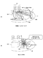
図1は、実施形態のビームトラッキングの技術が適用される移動通信システムの概略図である。図1(A)は垂直ビームフォーミングの例を示す。基地局10Aは複数のアンテナポートを構成するアンテナ21を有し、自局のサービスエリア11内に在圏するユーザ装置30A,30Bに対して、指向性を有する複数のビームでデータ信号と参照信号を送信する。ユーザ装置30A、30Bは、それぞれ自局にとって良好なビーム番号(BI:
Beam Index)を選択して、基地局10Aにフィードバックする。垂直ビームフォーミングにより、垂直方向あるいはセルの半径方向(基地局10Aから見たときの遠近方向)への移動に対しても追従が容易になる。
FIG. 1 is a schematic diagram of a mobile communication system to which the beam tracking technique of the embodiment is applied. FIG. 1A shows an example of vertical beam forming. The
Beam Index) is selected and fed back to the
図1(B)は、大規模MIMOの例を示す。図1(B)の例では、基地局10Bに接続されたリモート基地局10Cは、2次元配置された(N×M)アンテナ素子を有するアンテナ装置22を有し、指向性を有する複数のビームでデータ信号と参照信号を送信する。ユーザ装置30は良好なビーム番号を選択し、選択したビーム番号をリモート基地局10C経由で基地局10Bにフィードバックする。リモート基地局10Cは、ユーザ装置30との無線(RF:Radio Frequency)送受信およびRFフロントエンド処理を行い、基地局10Bはベースバンド処理を行う。基地局10Bとリモート基地局10Cを合せて「基地局10」としてもよい。
FIG. 1B illustrates an example of large-scale MIMO. In the example of FIG. 1B, the remote base station 10C connected to the base station 10B has an
図2は、アンテナ装置22の配置例を示す。図2(A)では、同一偏波のアンテナ素子23を2次元配置し、各素子がそれぞれアンテナポートを構成して64個のアンテナポートを提供する。
FIG. 2 shows an arrangement example of the
図2(B)では、直交偏波のアンテナ素子24を2次元配置し、各アンテナ素子24が直交する2つの偏波方向に対応して2つのアンテナポートを構成する。この例では、アンテナポート数は128となる。
In FIG. 2B, orthogonally polarized
図2(C)では、複数の素子群でひとつのアンテナポートを構成する。この例では、図2(B)と同様に、直交偏波のアンテナ素子24を用いているので、枠で囲まれた素子群25は、第1の偏波に対応するアンテナポートと、直交する第2の偏波に対応するアンテナポートの2つのアンテナポートを構成する。
In FIG. 2C, a plurality of element groups constitute one antenna port. In this example, since the orthogonally polarized
各アンテナポートに供給されるデータにプリコーディングベクトルの重み付けを乗算してアンテナポートごとに位相回転量(及び/または振幅)を調整することで、複数のアンテナポートから送信されるビームに指向性を持たせることができる。プリコーディングによりビーム利得を大きくしてより遠くまで電波を飛ばすことができる一方で、ビーム幅が狭くなる。そこで、基地局10は、ビーム幅が狭くなってもカバレッジに穴が生じないように、送信ビームをユーザ装置30に追従させるビームトラッキングを実行する。
By multiplying the data supplied to each antenna port by the weight of the precoding vector and adjusting the amount of phase rotation (and / or amplitude) for each antenna port, the directivity of the beams transmitted from the plurality of antenna ports is increased. You can have it. Pre-coding increases the beam gain and allows radio waves to travel farther, while reducing the beam width. Therefore, the
図3は、ビームトラッキングを行う際に、基地局10から送信されるビームストリームの概略図である。図3(A)と図3(B)はアンテナ装置からみたビームの方向を示し、紙面の横方向が水平または方位角方向、縦方向が垂直または仰俯角方向である。
FIG. 3 is a schematic diagram of a beam stream transmitted from the
図3(A)を参照すると、基地局10は、ユーザ装置30に対してデータ送信のために現在形成しているビーム#0の他に、ビーム#1〜#6でトラッキング用参照信号(TRS:Tracking Reference Signal)を送信する。ビーム#1〜#6は、現在のビーム#0がユーザ装置30に追従できなくなった場合に用いられるビーム候補である。データ送信用のビーム#0とビーム候補#1〜#6を合わせて、ビームトラッキング用のビームストリーム51Aが形成される。図3(A)は、あるビームの6方向に隣接ビームが配置される細密充填配置を用いているが、図3(B)のような格子状配置であってもよい。
Referring to FIG. 3A, the
ユーザ装置30は、ビームストリーム51Aを受信すると、各ビームの受信強度等を測定して、受信状態の良好なビーム番号を基地局10にフィードバックする。フィードバックされるビーム番号は最適なビーム番号であってもよいし、上位X個のビーム番号であってもよい。または、ビーム#0〜#6のすべてについて測定結果をフィードバックしても良いし,受信品質が良好な順あるいは測定結果が悪い順にフィードバックしてもよい。
When receiving the
一例として、ユーザ装置30が基地局10のアンテナから見て右方向へ移動している場合を考える。ユーザ装置30は現在のビーム#0で下りリンクデータを受信しているが、移動につれてビーム#2の測定レベルが最も高くなり得る。基地局10は、ユーザ装置30からビーム#2のフィードバックを受信すると、現在のビームをビーム#0からビーム#2に変更し、ビーム#2の周囲にビーム候補を配置してトラッキング用の参照信号(TRS)を送信する。
As an example, consider a case where the
データ送信用の現在のビーム#0の他にビーム#1〜#6でTRSを送信することで、7通り(3ビット)のビームを用いたビームトラッキングを実現することができる。ここで、必ずしもTRSという新たな参照信号を規定する必要はなく、たとえばプリコードされた(すなわち指向性を有する)チャネル測定用の参照信号(CSI−RS:Channel State Information Reference Signal)を用いてもよい。あるいは、既存のLTEシステムや、LTEを進化させたLTE-Advancedシステムで規定、検討されている参照信号や同期信号を利用してもよい。ビームトラッキングに使用し得る既存あるいは検討中の信号の例として、PSS(Primary Synchronization Signal),SSS(Secondary Synchronization Signal)、Enhanced SS等の同期信号や、Discovery signal, 復調用参照信号(DM−RS:Demodulation Reference Signal)などが挙げられるが、これらに限定されない。
By transmitting TRS using beams # 1 to # 6 in addition to the
現在のビーム#0に関しては、ユーザ装置はDM−RS等で受信品質を測定することができるので、必ずしもTRSなどのビームトラッキング用の参照信号を別途に送信しなくてもよい。
Regarding the
この方法によると、現在形成されているビーム#0の周囲で限られた数のCSI−RS(あるいはTRS)が送信されるので、RSオーバーヘッドを抑制することができる。他方、ユーザ装置30は複数の指向性で到来するTRSの中から受信品質の良好なビームを選択して基地局にフィードバックするので、ユーザ装置30の移動に追従した良好なビームで下りリンクデータを受信することができる。
According to this method, since a limited number of CSI-RSs (or TRSs) are transmitted around the currently formed
ユーザ装置30における信号の測定と選択は、受信電力レベル、SINR(Signal to Interference-plus-Noise Ratio)、TRSで測定したRSRP(Reference Signal Received Power)、RSRQ(Reference Signal Received Quality)など、任意のパラメータに基づいてすることができる。特にRSRPを用いることで、信号の測定と選択を簡易にしてもよい。
The measurement and selection of the signal in the
図3(B)では、隣接ビームが格子状に配置される格子状配置を用いる。現在形成されているビーム#0を中心として、水平方向と垂直方向に十字型にビーム候補#1〜#4が配置されたビームストリーム51Bが送信される。この構成でも3ビットで各ビームを識別することができ、RSオーバーヘッドを抑制することができる。
In FIG. 3B, a lattice arrangement in which adjacent beams are arranged in a lattice shape is used. A beam stream 51B in which beam candidates # 1 to # 4 are arranged in a cross shape in the horizontal direction and the vertical direction around the currently formed
図3(A)と図3(B)では、現在形成されているビーム#0に隣接してビーム候補の指向性を形成しているが、ビーム候補の方向は、必ずしも現在のビーム#0に物理的に隣接していなくてもよい。たとえば、ユーザ装置がアンテナ装置からみて右方向に比較的早い速度で移動している場合は、現在のビーム#0の右側のビーム候補#2を、ビーム#0の方向からある程度離れた方向に送信してもよいし、現在のビーム#0の右側にそれぞれ異なる方位角で2以上のビーム候補を配置してもよい。
In FIGS. 3A and 3B, the directivity of the beam candidate is formed adjacent to the currently formed
同様に、ユーザ装置がアンテナ装置に近づく方向(俯角方向)または下がる方向に移動している場合は、現在のビーム#0の下方のビーム#3を、ビーム#0の方向からある程度下方に離れた方向に送信してもよいし、現在のビーム#0の下方に向けて異なる俯角で2以上のビーム候補を配置してもよい。
Similarly, when the user apparatus is moving in a direction approaching the antenna apparatus (a depression angle direction) or a downward direction, the
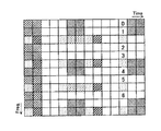
図4は、トラッキング用参照信号(TRS)の多重例を示す。従来のユーザ装置(レガシーUE)はTRSの存在を把握できないため、TRSを共有チャネルに多重した場合、レガシーUEの特性劣化が生じる。このため、ユーザ固有(User-specific)な領域に参照信号を多重することが有効であると考えられる。なお、TRSに限らず、従来のユーザ装置への特性劣化を抑圧する目的で参照信号をユーザ固有な領域に多重することは有効である。 FIG. 4 shows a multiplexing example of the tracking reference signal (TRS). Since the conventional user apparatus (legacy UE) cannot grasp the presence of TRS, when the TRS is multiplexed on the shared channel, the characteristic degradation of the legacy UE occurs. For this reason, it is considered effective to multiplex the reference signal in a user-specific area. Note that it is effective to multiplex a reference signal in a user-specific region for the purpose of suppressing characteristic degradation to a conventional user apparatus, not limited to TRS.
あるいは、レガシーUEの特性劣化を許容しつつ、共有チャネルに多重することも考えられる。この場合、トラッキング用参照信号(TRS)#0〜#6を、物理下りリンク共有チャネル(PDSCH)Physical Downlink Shared Channel)のサブフレームの最終シンボルまたは後半のシンボルに多重することで、TRSによる測定タイミングとデータの送信タイミングの時間的な差を小さくできるため、トラッキング精度を向上することができる。 Alternatively, multiplexing on a shared channel may be considered while allowing deterioration of characteristics of legacy UEs. In this case, the tracking reference signals (TRS) # 0 to # 6 are multiplexed on the final symbol or the latter half symbol of the subframe of the physical downlink shared channel (PDSCH), thereby measuring timing by TRS. Since the time difference between the data transmission timing and the data transmission timing can be reduced, the tracking accuracy can be improved.
図4の例では、スケジューリングされたPDSCHのサブフレームの最後から3つ目のシンボルでTRS#0〜#6が送信されている。この例に限定されず、後半の時間スロットの適切なシンボル位置に多重してもよい。
In the example of FIG. 4,
TRSを特にユーザ固有な領域に多重し、周波数的な多重密度を一定とする場合、PDSCHの送信帯域幅が狭い場合は周波数方向のTRSリソース数が減少してトラッキング精度が低下する。逆に、PDSCHの送信帯域幅が広い場合はトラッキング精度が高くなる。そこで、PDSCHの送信帯域が狭い場合にTRS送信の密度を高くし、PDSCHの送信帯域が広い場合にTRS送信の密度を低くなるように調整する。これにより、PDSCHの割り当て頻度や送信帯域に依存しない適度な推定精度を維持することができる。 When TRS is multiplexed particularly in a user-specific region and the frequency multiplexing density is constant, the number of TRS resources in the frequency direction decreases and tracking accuracy decreases when the PDSCH transmission bandwidth is narrow. Conversely, tracking accuracy increases when the PDSCH transmission bandwidth is wide. Therefore, the TRS transmission density is adjusted to be high when the PDSCH transmission band is narrow, and the TRS transmission density is adjusted to be low when the PDSCH transmission band is wide. Thereby, it is possible to maintain an appropriate estimation accuracy independent of the PDSCH allocation frequency and the transmission band.
TRSの送信に関し、基地局10にて、送信信号系列、時間多重位置(周期)、周波数多重位置(周期)、拡散符号化のための符号分割多重(CDM)系列、送信するTRSの数、フィードバックすべきビーム番号(BI:Beam Index)の数など、ビームトラッキングに必要な情報の一部または全部を設定(configure)してもよい。
Regarding transmission of TRS, the
異なるTRSで同一の送信信号系列を用い、時間多重位置、周波数多重位置、あるいはCDM系列だけを変える構成とすることでシグナリングビット数を削減してもよい。 The number of signaling bits may be reduced by using the same transmission signal sequence in different TRSs and changing only the time multiplexing position, the frequency multiplexing position, or the CDM sequence.
また、これらの設定情報は複数ビームのトラッキングを目的として、複数設定できてもよい。その場合、configuration番号として複数のビームを識別できてもよいし、端末に対してフィードバックを行うconfiguration番号を例えば動的に指定できてもよい。 A plurality of pieces of setting information may be set for the purpose of tracking a plurality of beams. In that case, a plurality of beams may be identified as the configuration number, and the configuration number for performing feedback to the terminal may be dynamically specified, for example.
これらの設定情報は、物理下りリンク制御チャネル(PDCCH:Physical Downlink Control Channel)あるいはePDCCH(enhanced Physical Downlink Control Channel)でダイナミックに通知されてもよいし、上位レイヤで準静的(semi-static)に通知されてもよいし、上位レイヤと下位レイヤの組み合わせにより通知されてもよい。 Such setting information may be notified dynamically on a physical downlink control channel (PDCCH) or ePDCCH (enhanced Physical Downlink Control Channel), or semi-statically in a higher layer. It may be notified, or may be notified by a combination of an upper layer and a lower layer.
図5は、複数のビームストリーム52、53が設定される例を示す。基地局10は、ビームトラッキング用に複数のビームストリームを設定可能である。基地局10は、ビームストリーム52と、ビームストリーム53のそれぞれについて同時にビームトラッキングを実行してもよい。トラッキング用のビームストリームの数は、送信ランク数に従っていてもよい。
FIG. 5 shows an example in which a plurality of beam streams 52 and 53 are set. The
十分なビーム追従精度を有している場合、フィードバック情報は現在のビーム番号(BI)で連続する可能性がある。そこで、複数のビームストリーム52、53に関して一括してフィードバック報告することによってフィードバックビット数を削減する構成をとることができる。 If there is sufficient beam tracking accuracy, the feedback information may continue with the current beam number (BI). Therefore, it is possible to adopt a configuration in which the number of feedback bits is reduced by collectively performing feedback reporting on the plurality of beam streams 52 and 53.
たとえば、フィードバック情報に1ビットのストリームインデックスを多重し、ビット値が「1」のときにビームストリーム53の変更要求を、ビット値が「0」のときにビームストリーム52の変更要求を表す構成としてもよい。また、3ビットを用いたビームトラッキングで"000"は、複数ビーム(TRS)のすべてについて変更不要であることを示す構成としてもよい。
For example, a stream index of 1 bit is multiplexed with feedback information, and a change request of the
次に、ユーザ装置30によるビーム番号(BI)のフィードバックについて説明する。ユーザ装置30は、現在の下りリンクデータ送信用のビームとビーム候補とを含むビームストリーム51を測定し、選択したビーム番号を基地局に通知する。
Next, feedback of the beam number (BI) by the
図4のように、特に基地局10からのトラッキング用参照信号(TRS)がPDSCHに多重されている場合は、ビーム番号をPDSCHに対応するACK/NACKに多重するのが効率的である。フィードバックは物理上り制御チャネル(PUCCH:Physical Uplink Control Channel)で行ってもよいし、物理上り共有チャネル(PUSCH:Physical Uplink Shared Channel)で行ってもよい。
As shown in FIG. 4, particularly when the tracking reference signal (TRS) from the
基地局10から複数のビームストリーム52、53が受信される場合、ユーザ装置30のフィードバック周期は、ビームストリーム52、53ごとに独立に設定してもよい。たとえば、図5のビームストリーム52が基地局からの直接波としてユーザ装置に届き、ビームストリーム53が反射波としてユーザ装置に届く場合、ビームストリーム52は、LOS(Line of Sight)波として到来するため、変動がそれほど大きくないと思われる。この場合、ビームストリーム52についてのフィードバック周期を、ビームストリーム53についてのフィードバック周期より大きく設定してオーバーヘッドを抑制する。
When a plurality of beam streams 52 and 53 are received from the
また、基地局10の主導でフィードバックトリガをユーザ装置30に送信する構成としてもよい。ユーザ装置30は、基地局10によるフィードバックトリガに従うことで、上り送信機会が抑制され、フィードバックのオーバーヘッドを低減できる。
Moreover, it is good also as a structure which transmits a feedback trigger to the
ユーザ装置30の移動速度が非常に速い場合など、ビームトラッキングが大きくずれたときに、受信品質の劣化が激しく基地局10にフィードバックすべきビーム番号を選択できない場合がある。この場合、ユーザ装置30は、3ビットのフィードバック情報を特定の値、たとえば"111"に設定して、ビームトラッキングの再設定を要求する構成としてもよい。
When the beam tracking is greatly deviated, such as when the moving speed of the
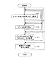
図6は、基地局10におけるビームトラッキングのフローチャートである。基地局10は、ビームトラッキングの開始に先立って、ユーザ装置30の方向、すなわちビームを形成すべき方向をラフに検出してから(S11)、ビーム方向の絞り込みを行ってもよい(S12)。ラフ検出は、PSS (Primary Synchronization Signal)/SSS (Secondary Synchronization Signal)、Discovery Signal、位置検出用の参照信号(PRS:Positioning Reference Signal)やGPS(Global Positioning System)を用いて行ってもよい。S11及びS12は本発明にとって必須ではないが、ある程度のビーム絞り込みを行うことで、ビームトラッキングを円滑に行うことができる。また、図6ではデータ送信はS13の後段のみに記載されているが、S11またはS12のセルエリア/ビーム選択結果に基づいてS11またはS12の後段でデータ送信を行うことも可能である。ユーザ装置30のおおよその位置は、一定間隔またはユーザ装置30から情報に基づいて繰り返し検出される。同様にビームの絞り込みも、一定間隔またはユーザ装置30からの情報に基づいて繰り返される。ユーザ位置の変化に応じて、ビーム絞り込み後に、S11に戻って位置検出から繰り返してもよいし、S12だけを繰り返してもよい。
FIG. 6 is a flowchart of beam tracking in the
基地局10は、ビームトラッキング用のビームストリームを送信する(S13)。このとき、図4または図5に示すように、1または複数のビームストリームが送信されてもよい。ビームストリームを構成する複数のTRS信号は、それぞれプリコーディングされて所望の指向性が与えられる。図4の例に基づくと、ビーム#0でユーザ装置30に対するデータ信号が送信されるとともに、ビーム#1〜#6でビームトラッキング用の参照信号(TRSなど)が送信される。基地局10は、ユーザ装置30からビームストリームの受信結果を取得して、最適なビームを選択する(S14)。基地局10はビームトラッキング用の参照信号の送信(S13)と、ユーザ装置30からの情報に基づく最適ビーム選択(S14)を繰り返すことで、送信ビームをユーザ装置に追従させることができる。参照信号の送信(S13)の後、あるいは最適ビーム選択(S14)の後に、S13に戻って処理を繰り返してももよいし、S11またはS12に戻って処理をやり直してもよい。たとえば送信ビームがユーザ装置30に追従できていない場合にS11あるいはS12に戻ってユーザ装置30の現在の方向を特定し直してもよい。
The
図7は、基地局10の概略構成図である。基地局10は、複数のアンテナ110−1〜110−Nを有し、アンテナ数に応じた無線(RF)送信回路107−1〜107−Nおよび無線(RF)受信回路111−1〜111−Nを有する。
FIG. 7 is a schematic configuration diagram of the
送信データは、直並列変換部106で、たとえば、誤り訂正符号化の単位であり再送単位であるコードワードごとに並列データに変換され、チャネル符号化及び変調を受けて、コードワード対レイヤマッピング部102で対応するレイヤにマッピングされる。レイヤマッピングされた送信データは、リソース割り当て制御の下に、サブキャリアマッピング部105でサブキャリアにマッピングされる。このとき、TRSやCSI−RSなどの参照信号も、サブキャリアにマッピングされる。ここで、参照信号はすでにプリコーディングされていてもよい。図4のように、トラッキング用の参照信号が共有チャネルに多重される場合は、送信フレームの後半部分のシンボル位置にマッピングされるのが望ましい。
The transmission data is converted into parallel data for each codeword which is a unit of error correction coding and a retransmission unit by the serial-parallel conversion unit 106, and is subjected to channel coding and modulation. In 102, it is mapped to the corresponding layer. The transmission data subjected to layer mapping is mapped to subcarriers by the
サブキャリアにマッピングされた送信データと参照信号は、プリコーディング部103に入力される。プリコーディング部103は、各アンテナ110−1〜110−Nに供給される送信データ及び参照信号(ビームトラッキング用のTRSを含む)にプリコーディングベクトルを乗算する。ここで、プリコーディングを乗算するのは入力信号の一部であってもよい。たとえば、参照信号はサブキャリアマッピングの前段でプリコードされてもよい。
The transmission data and the reference signal mapped to the subcarrier are input to the
プリコーディングにより重み付け(位相回転量および/あるいは振幅変動量の調整)がされた送信信号は、マルチプレクサ104からアンテナ110ごとの送信信号として出力される。各送信信号は図示しない離散フーリエ変換(DFT)、逆フーリエ変換(IFFT)、サイクリック・プレフィクスの付加を経て、RF送信回路107−1〜107−Nで無線周波数の信号に変換される。無線信号は、デュプレクサ108−1〜108−Nを介して対応するアンテナ111−1〜111−Nから送信される。
A transmission signal weighted (adjustment of phase rotation amount and / or amplitude fluctuation amount) by precoding is output from
ユーザ装置30からのフィードバック信号は、アンテナ110−1〜110−N、デュプレクサ108−1〜108−Nを介して、RF受信回路111−1〜111−Nに入力されてベースバンド信号に変換される。ベースバンド信号から制御信号とデータチャネル信号が分離され、チャネル推定部118の推定値に基づいて、フィードバック情報処理制御部119でフィードバック情報が復調される。チャネル推定用の参照信号に基づくチャネル推定部118の動作や、データ信号の復調(データチャネル信号復調部117の動作)や復号、並直列変換部126の動作については、発明と直接関連しないので、説明を省略する。
Feedback signals from the
フィードバック情報処理制御部119は、フィードバック情報にビームインデックスが含まれるか、あるいはビームトラッキング外れが生じていないかを判断する。フィードバック情報にユーザ装置30からのビームインデックスが含まれている場合は、ビームインデックスをプリコーディングウェイト生成部122に通知する。フィードバック情報に複数のビームインデックスが含まれている場合は、最適なビームインデックスとビーム候補用のビームインデックスを選択してプリコーディングウェイト生成部122に通知する。プリコーディングウェイト生成部122は、ビームインデックスに応じたプリコーディングベクトルを生成する。
The feedback information
フィードバック情報がビームトラッキング外れを示す場合(たとえば"111"が示される場合など)は、ビームの絞り込み等を行って、プリコーディングウェイト生成部122にプリコーディングウェイトの再設定を指示してもよい。
When the feedback information indicates beam tracking loss (for example, when “111” is indicated), the precoding
復調されたフィードバック情報は送信ランク選択部121にも供給される。プリコーディングウェイト生成部122は、送信ランク選択部121で選択されたランク数に応じた数のビームストリームを形成するように、プリコーディングウェイトセットを生成してもよい。
The demodulated feedback information is also supplied to the transmission
図8は、ユーザ装置30で行われる処理フローである。ユーザ装置30は、ユーザ装置30宛ての下りリンクデータとともに、ビーム候補を含むトラッキング用ビームストリームを受信する(S31)。受信したデータ信号及びトラッキング用ビーム候補を測定し(S32)、適切なビーム番号をフィードバック情報に含めて基地局に送信する(S33)。また、受信したビームストリームに閾値を超える受信品質のビームが含まれていない場合は、特定の値(たとえば"111"等)のフィードバック情報を返してもよい。また、受信したビームストリームの品質が良好であり、ビーム変更が不要の場合は、別の特定の値(たとえば"000")を返してもよい。基地局10から複数のビームストリームを受信したときは、変更を要するビームストリームを特定するストリーム番号をフィードバック情報に含めてもよい。
FIG. 8 is a processing flow performed by the
図9は、ユーザ装置30の概略構成図である。ユーザ装置30は、基地局10から送信されたデータ信号及びビームトラッキング用の参照信号(TRS)を、アンテナ307−1〜307−Mで受信し、デュプレクサ306−1〜306−Mを介してRF受信回路308−1〜308−Mに入力してベースバンド信号に受信する。ベースバンド信号は図示しないサイクリック・プリフィクスの除去や高速フーリエ変換を経て、データ信号、参照信号、制御信号等に分離される。
FIG. 9 is a schematic configuration diagram of the
チャネル推定部312で推定されたチャネル状態に基づいて復調された参照信号(CSI−RSやTRSを含む)は、チャネル品質測定部315に入力され、チャネル品質が測定される。ランク・プリコーディングウェイト選択部314は、測定されたチャネル品質に基づいて、ランクインデックスとプリコーディングウェイトを選択する。
A reference signal (including CSI-RS and TRS) demodulated based on the channel state estimated by the
フィードバック信号生成部316は、受信したビームビームストリームから1つまたは複数の良好なビームインデックスを選択してフィードバック信号を生成する。良好なビーム番号がない場合は、たとえば"111"などの値を含むフィードバック信号を生成し、ビームに変更がない場合は、たとえば"000"などの値を含むフィードバック信号を生成する。複数のTRSビームストリームを受信したときは、複数のビームストリームに関する選択情報を一括して示すストリームインデックス用のビットをフィードバック情報に追加してもよい。
The feedback
生成されたフィードバック情報は、マルチプレクサ302にて、プリコードされた上りリンク送信データや参照信号と合成され、アンテナ307ごとの送信データとして出力される。フィードバック情報を含む送信データは、RF送信回路305−1〜305−Mで無線周波数の信号に変換される。無線信号はデュプレクサ306−1〜306−Mを介して対応するアンテナ307−1〜307−Mから送信される。
The generated feedback information is combined with the precoded uplink transmission data and the reference signal by the
上記の手法と構成により、プリコーディングによる指向性の強いビームを形成する場合に、効率よく送信ビームユーザ装置に追従させることができる。 With the above method and configuration, when a beam having strong directivity by precoding is formed, it is possible to efficiently follow the transmission beam user apparatus.
なお、上述した技術は、マルチユーザ(MU)MIMOにも適用可能である。この場合は、同時多重されているユーザ装置に適用してほしいビーム番号、すなわち、他ユーザからの干渉が小さくなるビーム番号を基地局10にフィードバックしてもよい。
(付記)
以上説明した実施の形態に関し、更に以下の付記のようにも記載できる。
(付記1)
複数のアンテナポートを有する基地局と、前記基地局と無線通信を行うユーザ装置とを含む移動通信システムにおいて、
前記基地局は、前記ユーザ装置に対してデータを送信する第1ビームと、前記第1ビームの周辺方向にプリコードされた参照信号を送信する一つまたは複数の第2ビームとを含むビームストリームを送信し、
前記ユーザ装置は、前記ビームストリームを受信して、前記第1ビームおよび前記第2ビームの中から1以上の適切なビーム番号を選択して前記基地局に通知する、
ことを特徴とする移動通信システム。
(付記2)
前記基地局は、前記参照信号を、下りリンク共有チャネルのユーザ固有の領域に多重することを特徴とする付記1に記載の移動通信システム。
(付記3)
前記基地局は、前記参照信号の送信信号系列、時間多重位置(周期)、周波数多重位置(周期)、拡散符号化のための符号分割多重(CDM)系列、送信する参照信号の数、フィードバックすべきビーム番号の数の一部または全部を設定して、前記ユーザ装置に通知することを特徴とする付記2に記載の移動通信システム。
(付記4)
前記移動局は、前記ビームストリームを前記下りリンク共有チャネルで受信したときに選択した前記ビーム番号を、肯定応答または否定応答に多重して送信することを特徴とする付記2に記載の移動通信システム。
(付記5)
前記基地局は、前記ユーザ装置に対して複数の前記ビームストリームを設定して、前記ビームストリームのそれぞれについてビームトラッキングを実施し、
前記ユーザ装置は、前記複数のビームストリームの追従状態を一括して表す情報をフィードバック情報に含めて送信することを特徴とする付記1に記載の移動通信システム。
(付記6)
データ信号と、前記データとともに送信される一つまたは複数の参照信号をそれぞれ対応するプリコーディングベクトルで乗算するプリコーディング部と、
複数のアンテナポートを有し、前記データ信号を送信する第1ビームと、前記参照信号を前記第1ビームの周辺方向に向けて送信する第2ビームとを空間多重して送信するアンテナ部と、
ユーザ装置から前記第1ビームおよび前記第2ビームの受信結果を取得し、前記受信結果に基づいて前記プリコーディング部を制御して前記第1ビームを前記ユーザ装置に追従させる制御部と、
を有することを特徴とする基地局。
(付記7)
前記参照信号を下りリンク共有チャネルのユーザ固有の領域に多重する多重部、
をさらに有することを特徴とする付記6に記載の基地局。
(付記8)
前記制御部は、前記参照信号の送信信号系列、時間多重位置(周期)、周波数多重位置(周期)、拡散符号化のための符号分割多重(CDM)系列、送信する参照信号の数、フィードバックすべきビーム番号の数の一部または全部を設定して前記ユーザ装置に通知することを特徴とする付記7に記載の基地局。
(付記9)
基地局からのデータ信号を第1ビームで受信するとともに、前記第1ビームの周辺に向けられる複数の第2ビームでプリコードされた一つまたは複数の参照信号を受信する受信部と、
前記データ信号および前記複数の参照信号を測定する測定部と、
前記測定部の測定結果に基づいて前記第1ビームと前記第2ビームの中から1以上のビームを選択して選択結果を前記基地局に通知する制御部と、
を有することを特徴とするユーザ装置。
(付記10)
前記受信部は、前記参照信号を下りリンク共有チャネルのユーザ固有の領域で受信することを特徴とする付記9に記載のユーザ装置。
The technique described above can also be applied to multi-user (MU) MIMO. In this case, the beam number that is desired to be applied to the user equipment that is multiplexed at the same time, that is, the beam number that reduces interference from other users may be fed back to the
(Appendix)
The embodiment described above can be further described as the following supplementary notes.
(Appendix 1)
In a mobile communication system including a base station having a plurality of antenna ports and a user apparatus that performs radio communication with the base station,
The base station includes a beam stream including a first beam that transmits data to the user apparatus, and one or more second beams that transmit a reference signal precoded in a peripheral direction of the first beam. Send
The user apparatus receives the beam stream, selects one or more appropriate beam numbers from the first beam and the second beam, and notifies the base station of the selected beam number.
A mobile communication system.
(Appendix 2)
The mobile communication system according to supplementary note 1, wherein the base station multiplexes the reference signal in a user-specific region of a downlink shared channel.
(Appendix 3)
The base station transmits a transmission signal sequence of the reference signal, a time multiplexing position (period), a frequency multiplexing position (period), a code division multiplexing (CDM) sequence for spreading coding, the number of reference signals to be transmitted, and feedback. The mobile communication system according to
(Appendix 4)
The mobile communication system according to
(Appendix 5)
The base station sets a plurality of the beam streams for the user equipment, performs beam tracking for each of the beam streams,
The mobile communication system according to supplementary note 1, wherein the user apparatus transmits information including feedback information collectively indicating a tracking state of the plurality of beam streams.
(Appendix 6)
A precoding unit for multiplying a data signal and one or more reference signals transmitted together with the data by a corresponding precoding vector;
An antenna unit that has a plurality of antenna ports and that spatially multiplexes and transmits a first beam that transmits the data signal and a second beam that transmits the reference signal in a peripheral direction of the first beam;
A control unit that obtains reception results of the first beam and the second beam from a user apparatus, controls the precoding unit based on the reception result, and causes the user apparatus to follow the first beam;
A base station characterized by comprising:
(Appendix 7)
A multiplexing unit for multiplexing the reference signal in a user-specific region of a downlink shared channel;
The base station according to
(Appendix 8)
The control unit includes a transmission signal sequence of the reference signal, a time multiplexing position (period), a frequency multiplexing position (period), a code division multiplexing (CDM) sequence for spreading coding, the number of reference signals to be transmitted, and feedback. The base station according to appendix 7, wherein a part or all of the number of power beam numbers is set and notified to the user apparatus.
(Appendix 9)
A receiver for receiving a data signal from a base station with a first beam and receiving one or a plurality of reference signals precoded with a plurality of second beams directed around the first beam;
A measurement unit for measuring the data signal and the plurality of reference signals;
A control unit for selecting one or more beams from the first beam and the second beam based on the measurement result of the measurement unit and notifying the base station of the selection result;
A user apparatus comprising:
(Appendix 10)
The user apparatus according to appendix 9, wherein the receiving unit receives the reference signal in a user-specific region of a downlink shared channel.
10、10A、10B,10C 基地局
30、30A、30B ユーザ装置
51A、51B、52、53 ビームトラッキング用のビームストリーム
103 基地局のプリコーディング部
105 サブキャリアマッピング部
110−1〜110−N 基地局のアンテナ
119 フィードバック情報処理制御部
122 プリコーディングウェイト生成部
301 ユーザ装置のプリコーディング部
307−1〜207−M ユーザ装置のアンテナ
316 フィードバック信号生成部
10, 10A, 10B,
Claims (10)
前記基地局は、前記ユーザ装置に対してプリコードされた複数のチャネル測定用参照信号に対応する複数のビームを含むビームストリームを送信し、
前記ユーザ装置は、前記複数のビームを受信して、前記複数のビームの中から1以上のビームを選択して前記基地局に通知する、
ことを特徴とする移動通信システム。 In a mobile communication system including a base station having a plurality of antenna ports and a user apparatus that performs radio communication with the base station,
The base station transmits a beam stream including a plurality of beams corresponding to a plurality of channel measurement reference signals precoded for the user apparatus,
The user apparatus receives the plurality of beams, selects one or more beams from the plurality of beams, and notifies the base station;
A mobile communication system.
前記ユーザ装置は、前記複数のビームストリームの追従状態を一括して表す情報をフィードバック情報に含めて送信することを特徴とする請求項1に記載の移動通信システム。 The base station sets a plurality of the beam streams for the user equipment, performs beam tracking for each of the beam streams,
2. The mobile communication system according to claim 1, wherein the user apparatus transmits feedback information including information collectively indicating the tracking states of the plurality of beam streams.
複数のアンテナポートを有し、前記複数のチャネル測定用参照信号に対応する複数のビームを含むビームストリームを送信するアンテナ部と、
ユーザ装置から前記複数のビームの受信結果を取得する制御部と、
を有することを特徴とする基地局。 A precoding unit for multiplying a plurality of channel measurement reference signals by corresponding precoding vectors, and
An antenna unit having a plurality of antenna ports and transmitting a beam stream including a plurality of beams corresponding to the plurality of channel measurement reference signals;
A control unit for obtaining reception results of the plurality of beams from a user device;
A base station characterized by comprising:
をさらに有することを特徴とする請求項6に記載の基地局。 A multiplexing unit that multiplexes the plurality of channel measurement reference signals in a user-specific region of a downlink shared channel;
The base station according to claim 6, further comprising:
前記複数のチャネル測定用参照信号を測定する測定部と、
前記測定部の測定結果に基づいて前記複数のビームの中から1以上のビームを選択して選択結果を前記基地局に通知する制御部と、
を有することを特徴とするユーザ装置。 A receiving unit for receiving the plurality of beams included in a beam stream including a plurality of beams corresponding to a plurality of precoded channel measurement reference signals transmitted from the base station;
A measurement unit for measuring the plurality of channel measurement reference signals;
A control unit that selects one or more beams from the plurality of beams based on the measurement result of the measurement unit and notifies the base station of the selection result;
A user apparatus comprising:
The user apparatus according to claim 9, wherein the reception unit receives the plurality of channel measurement reference signals in a user-specific region of a downlink shared channel.
Priority Applications (6)
| Application Number | Priority Date | Filing Date | Title |
|---|---|---|---|
| JP2014059180A JP6121931B2 (en) | 2014-03-20 | 2014-03-20 | Mobile communication system, base station, and user equipment |
| EP14886105.7A EP3122094A4 (en) | 2014-03-20 | 2014-11-27 | Mobile communication system, base station, and user device |
| PCT/JP2014/081369 WO2015141065A1 (en) | 2014-03-20 | 2014-11-27 | Mobile communication system, base station, and user device |
| CN201480077121.4A CN106105292B (en) | 2014-03-20 | 2014-11-27 | Mobile communication system, base station, and user equipment |
| US15/126,101 US11350291B2 (en) | 2014-03-20 | 2014-11-27 | Beam tracking mobile communication system, base station, and user equipment |
| ZA2016/06615A ZA201606615B (en) | 2014-03-20 | 2016-09-23 | Mobile communication system, base station, and user equipment |
Applications Claiming Priority (1)
| Application Number | Priority Date | Filing Date | Title |
|---|---|---|---|
| JP2014059180A JP6121931B2 (en) | 2014-03-20 | 2014-03-20 | Mobile communication system, base station, and user equipment |
Publications (3)
| Publication Number | Publication Date |
|---|---|
| JP2015185952A JP2015185952A (en) | 2015-10-22 |
| JP2015185952A5 JP2015185952A5 (en) | 2016-12-22 |
| JP6121931B2 true JP6121931B2 (en) | 2017-04-26 |
Family
ID=54144061
Family Applications (1)
| Application Number | Title | Priority Date | Filing Date |
|---|---|---|---|
| JP2014059180A Active JP6121931B2 (en) | 2014-03-20 | 2014-03-20 | Mobile communication system, base station, and user equipment |
Country Status (6)
| Country | Link |
|---|---|
| US (1) | US11350291B2 (en) |
| EP (1) | EP3122094A4 (en) |
| JP (1) | JP6121931B2 (en) |
| CN (1) | CN106105292B (en) |
| WO (1) | WO2015141065A1 (en) |
| ZA (1) | ZA201606615B (en) |
Cited By (1)
| Publication number | Priority date | Publication date | Assignee | Title |
|---|---|---|---|---|
| US11159957B2 (en) | 2018-01-19 | 2021-10-26 | Nec Corporation | Base station apparatus, service provision method, and program |
Families Citing this family (65)
| Publication number | Priority date | Publication date | Assignee | Title |
|---|---|---|---|---|
| KR102309726B1 (en) * | 2014-07-10 | 2021-10-07 | 삼성전자 주식회사 | Communicating method in a wireless communication system using bean forminig and system thereof |
| CN106537802B (en) * | 2014-07-24 | 2020-09-08 | Lg电子株式会社 | Method and apparatus for transmitting feedback signal |
| KR102004383B1 (en) * | 2014-07-25 | 2019-07-26 | 후아웨이 테크놀러지 컴퍼니 리미티드 | Communications device and method in high-frequency system |
| KR20170097708A (en) * | 2014-12-17 | 2017-08-28 | 후아웨이 테크놀러지 컴퍼니 리미티드 | Precoding information collection method and transmission device |
| US20160219570A1 (en) * | 2015-01-26 | 2016-07-28 | Asustek Computer Inc. | Method and apparatus for handling transmission in a wireless communication system |
| US10305584B2 (en) * | 2015-10-20 | 2019-05-28 | Samsung Electronics Co., Ltd. | Apparatus and method for performing beamforming operation in communication system supporting frequency division-multiple input multiple output scheme |
| WO2017082256A1 (en) * | 2015-11-09 | 2017-05-18 | 株式会社ソニー・インタラクティブエンタテインメント | Main beam direction determination device, head-mounted display, method for determining main beam direction, and program |
| CN106850009B (en) | 2015-11-30 | 2021-02-09 | 华为技术有限公司 | Method for determining communication beam and corresponding device |
| US9930656B2 (en) * | 2015-12-21 | 2018-03-27 | Intel IP Corporation | Cell search and synchronization in millimeter-wave capable small cells |
| US10700752B2 (en) | 2016-01-14 | 2020-06-30 | Samsung Electronics Co., Ltd. | System, method, and apparatus of beam-tracking and beam feedback operation in a beam-forming based system |
| KR20170085428A (en) * | 2016-01-14 | 2017-07-24 | 삼성전자주식회사 | System, Method, and Apparatus of Beam Tracking and Beam Feedback Operation in a Beam-forming based System |
| CN108886742B (en) * | 2016-02-03 | 2022-11-08 | 株式会社Ntt都科摩 | Beamforming common channel in 5G new radio |
| WO2017135455A1 (en) * | 2016-02-04 | 2017-08-10 | 株式会社Nttドコモ | User equipment, and random access method |
| US10425200B2 (en) | 2016-04-13 | 2019-09-24 | Qualcomm Incorporated | System and method for beam adjustment request |
| US10615862B2 (en) | 2016-04-13 | 2020-04-07 | Qualcomm Incorporated | System and method for beam adjustment request |
| US11791882B2 (en) | 2016-04-13 | 2023-10-17 | Qualcomm Incorporated | System and method for beam management |
| US10116483B2 (en) | 2016-04-18 | 2018-10-30 | Qualcomm Incorporated | Dynamically convey information of demodulation reference signal and phase noise compensation reference signal |
| KR102344710B1 (en) | 2016-05-12 | 2021-12-31 | 인터디지탈 패튼 홀딩스, 인크 | System and method for beamforming feedback in millimeter wave wireless local area network |
| US10141999B2 (en) | 2016-05-27 | 2018-11-27 | Telefonaktiebolaget Lm Ericsson (Publ) | Reference signal tracking in a wireless communication system |
| JP6634982B2 (en) * | 2016-07-29 | 2020-01-22 | ソニー株式会社 | Terminal device, base station, method and recording medium |
| US10554284B2 (en) * | 2016-08-01 | 2020-02-04 | Qualcomm Incorporated | Beam refinement for active and candidate beams |
| CN110417450B (en) | 2016-08-10 | 2021-08-03 | 华为技术有限公司 | Beam tracking method, terminal equipment and network side equipment |
| US11071145B2 (en) | 2016-08-12 | 2021-07-20 | Qualcomm Incorporated | Rach conveyance of DL synchronization beam information for various DL-UL correspondence states |
| CN115361046A (en) | 2016-09-21 | 2022-11-18 | 松下电器(美国)知识产权公司 | Transmission method, transmission device, reception method, and reception device |
| CN107872253B (en) * | 2016-09-27 | 2021-06-08 | 华为技术有限公司 | Beam tracking method, device and system |
| JP6810250B2 (en) * | 2016-10-03 | 2021-01-06 | ノキア テクノロジーズ オーユー | Reference signal for beamforming training and channel estimation |
| US10154496B2 (en) * | 2016-11-10 | 2018-12-11 | Futurewei Technologies, Inc. | System and method for beamformed reference signals in three dimensional multiple input multiple output communications systems |
| US11228358B2 (en) * | 2016-12-13 | 2022-01-18 | Guangdong Oppo Mobile Telecommunications Corp., Ltd. | Signal transmission method, terminal device and network device |
| CN110140372B (en) * | 2017-01-05 | 2022-12-23 | 日本电气株式会社 | Base station, terminal device, method, program, and recording medium |
| EP3567893A4 (en) * | 2017-01-06 | 2020-10-07 | NTT DoCoMo, Inc. | User terminal and wireless communication method |
| WO2018129300A1 (en) * | 2017-01-06 | 2018-07-12 | Idac Holdings, Inc. | Beam failure recovery |
| EP3573269B1 (en) * | 2017-01-20 | 2021-12-29 | LG Electronics Inc. | Beam control method for direct communication between terminals in wireless communication system |
| WO2018147346A1 (en) * | 2017-02-10 | 2018-08-16 | 株式会社Nttドコモ | User terminal and wireless communication method |
| JPWO2018163230A1 (en) * | 2017-03-06 | 2019-03-14 | 三菱電機株式会社 | Mobile terminal, radio base station, and beam transmission / reception method |
| WO2018168670A1 (en) * | 2017-03-17 | 2018-09-20 | 株式会社Nttドコモ | User terminal and positioning method |
| US10499390B2 (en) * | 2017-03-24 | 2019-12-03 | Institute For Information Industry | Base station, user equipment, transmission control method for base station and data transmission method for user equipment |
| CN115087100B (en) * | 2017-05-03 | 2024-04-16 | Idac控股公司 | Method and apparatus for paging procedure in New Radio (NR) |
| CN108809367A (en) * | 2017-05-04 | 2018-11-13 | 株式会社Ntt都科摩 | Beam information feedback method and user apparatus |
| US10637625B2 (en) | 2017-05-05 | 2020-04-28 | Mediatek Inc. | Tracking reference signal and framework thereof in mobile communications |
| TWI678896B (en) * | 2017-05-05 | 2019-12-01 | 聯發科技股份有限公司 | Tracking reference signal and framework thereof in mobile communications |
| CN108809580B (en) | 2017-05-05 | 2023-04-14 | 北京三星通信技术研究有限公司 | Method for transmitting uplink signal, user equipment and base station |
| US10530548B2 (en) * | 2017-05-15 | 2020-01-07 | Futurewei Technologies, Inc. | Unifying message to support downlink beam management over multiple groups of beam paired links (MGBPL) |
| US11171700B2 (en) | 2017-06-01 | 2021-11-09 | Sony Interactive Entertainment Inc. | Main beam direction determining device, main beam direction determining method, and program |
| KR102417833B1 (en) | 2017-07-28 | 2022-07-06 | 삼성전자주식회사 | Apparatus and method for controlling directivity in wireless communication system |
| US10757583B2 (en) * | 2017-08-10 | 2020-08-25 | Qualcomm Incorporated | Uplink-based positioning reference signaling in multi-beam systems |
| US10257836B1 (en) | 2017-09-15 | 2019-04-09 | At&T Intellectual Property I, L.P. | Joint procedure for beam management and partial control beam failure recovery |
| CN109863700B (en) * | 2017-09-30 | 2022-08-19 | 北京小米移动软件有限公司 | Data transmission method and device |
| US11258566B2 (en) * | 2017-10-18 | 2022-02-22 | Qualcomm Incorporated | Aperiodic tracking reference signal |
| DE112018006728T5 (en) * | 2017-12-29 | 2020-10-29 | Keysight Technologies Singapore (Sales) Pte. Ltd. | TEST DEVICE FOR TESTING A TELECOMMUNICATION NETWORK AND METHOD FOR TESTING A TELECOMMUNICATION |
| WO2019148455A1 (en) * | 2018-02-02 | 2019-08-08 | Guangdong Oppo Mobile Telecommunications Corp., Ltd. | User equipment and method of wireless communication of same |
| RU2752244C1 (en) * | 2018-02-20 | 2021-07-23 | Нтт Докомо, Инк. | User device and base station |
| EP3788723A1 (en) * | 2018-05-03 | 2021-03-10 | Telefonaktiebolaget Lm Ericsson (Publ) | Systems and methods of controlling a component of a network node in a communication system |
| JP7216098B2 (en) | 2018-07-27 | 2023-01-31 | 株式会社Nttドコモ | Terminal, wireless communication method and system |
| WO2020021723A1 (en) * | 2018-07-27 | 2020-01-30 | 株式会社Nttドコモ | Base station and wireless communication method |
| CN112534863A (en) * | 2018-08-10 | 2021-03-19 | 索尼公司 | Wireless communication apparatus and communication control method |
| CN111464473B (en) * | 2019-01-18 | 2021-08-03 | 成都华为技术有限公司 | Method and device for configuring information |
| US10849132B2 (en) * | 2019-03-01 | 2020-11-24 | Arris Enterprises Llc | Rapid determination of an antenna pattern |
| WO2020213127A1 (en) * | 2019-04-18 | 2020-10-22 | 株式会社Nttドコモ | User terminal and wireless communication method |
| CN114303406A (en) * | 2019-09-12 | 2022-04-08 | 松下电器(美国)知识产权公司 | Communication device and communication method |
| CN112751596B (en) * | 2019-10-31 | 2022-08-02 | 中国电信股份有限公司 | Apparatus and method for millimeter wave beam alignment |
| US11329710B2 (en) | 2019-11-08 | 2022-05-10 | At&T Intellectual Property I, L.P. | Facilitation of beam failure indication for multiple transmission points for 5G or other next generation network |
| CN113315549B (en) * | 2020-02-27 | 2023-12-22 | 北京新岸线移动多媒体技术有限公司 | Wireless transmission method and device |
| GB2601815B (en) * | 2020-12-11 | 2023-05-03 | Cambium Networks Ltd | Establishing wireless communication in a system forming a beam by selecting from a pre-determined plurality of antenna weight vectors |
| WO2022123051A1 (en) * | 2020-12-11 | 2022-06-16 | Cambium Networks Ltd | Establishing wireless communication in a system forming a beam by selecting from a pre-determined plurality of antenna weight vectors |
| US11641642B2 (en) * | 2021-01-14 | 2023-05-02 | Qualcomm Incorporated | UE beam reselection procedure with CSI reporting and beam switch indication |
Family Cites Families (17)
| Publication number | Priority date | Publication date | Assignee | Title |
|---|---|---|---|---|
| JP2006287757A (en) * | 2005-04-01 | 2006-10-19 | Ntt Docomo Inc | Transmitter and transmitting method for downward link channel |
| JP5153006B2 (en) * | 2007-03-30 | 2013-02-27 | パナソニック株式会社 | Wireless communication system, wireless communication apparatus, and wireless communication method |
| JP5037615B2 (en) * | 2007-07-05 | 2012-10-03 | パナソニック株式会社 | Wireless communication apparatus, wireless communication system, and wireless communication method |
| US8676133B2 (en) * | 2008-09-19 | 2014-03-18 | Qualcomm Incorporated | Reference signal design for LTE A |
| JP5432210B2 (en) | 2011-05-02 | 2014-03-05 | 株式会社Nttドコモ | User terminal, radio base station, downlink control channel receiving method, and mobile communication system |
| KR101800221B1 (en) * | 2011-08-11 | 2017-11-22 | 삼성전자주식회사 | Method and apparatus for beam tracking in wireless communication system |
| KR101847400B1 (en) | 2011-09-01 | 2018-04-10 | 삼성전자주식회사 | Apparatus and method for selecting best beam in wireless communication system |
| US10264478B2 (en) * | 2011-12-16 | 2019-04-16 | Samsung Electronics Co., Ltd. | Methods and apparatus to enhance reliability in millimeter wave wideband communications |
| WO2013117231A1 (en) * | 2012-02-10 | 2013-08-15 | Nokia Siemens Networks Oy | Method and apparatus for transmitting a reference signal in a communication system |
| KR101995357B1 (en) * | 2012-02-17 | 2019-07-02 | 삼성전자주식회사 | Method and apparatus for operating control channel for beam-formed wireless communiations |
| US9236916B2 (en) * | 2012-03-15 | 2016-01-12 | Telefonaktiebolaget Lm Ericsson | Node and method for generating beamformed for downlink communications |
| US9119209B2 (en) * | 2012-03-30 | 2015-08-25 | Samsung Electronics Co., Ltd. | Apparatus and method for channel-state-information pilot design for an advanced wireless network |
| US9161241B2 (en) * | 2012-03-30 | 2015-10-13 | Nokia Solutions And Networks Oy | Reference signal design and signaling for per-user elevation MIMO |
| JP6121118B2 (en) * | 2012-09-07 | 2017-04-26 | 株式会社Nttドコモ | Wireless communication method, user terminal, wireless base station, and wireless communication system |
| US9571248B2 (en) * | 2012-10-29 | 2017-02-14 | Lg Electronics Inc. | Method and apparatus for configuring a reference signal in a wireless communication system |
| KR102084638B1 (en) * | 2013-01-11 | 2020-03-05 | 삼성전자 주식회사 | Apparatus and method for transmitting/receiving downlink data in a radio communication system using a cooperative multi-point transmission |
| WO2014117352A1 (en) | 2013-01-31 | 2014-08-07 | Qualcomm Incorporated | 3d mimo csi feedback based on virtual elevation ports |
-
2014
- 2014-03-20 JP JP2014059180A patent/JP6121931B2/en active Active
- 2014-11-27 CN CN201480077121.4A patent/CN106105292B/en active Active
- 2014-11-27 US US15/126,101 patent/US11350291B2/en active Active
- 2014-11-27 WO PCT/JP2014/081369 patent/WO2015141065A1/en active Application Filing
- 2014-11-27 EP EP14886105.7A patent/EP3122094A4/en active Pending
-
2016
- 2016-09-23 ZA ZA2016/06615A patent/ZA201606615B/en unknown
Cited By (1)
| Publication number | Priority date | Publication date | Assignee | Title |
|---|---|---|---|---|
| US11159957B2 (en) | 2018-01-19 | 2021-10-26 | Nec Corporation | Base station apparatus, service provision method, and program |
Also Published As
| Publication number | Publication date |
|---|---|
| EP3122094A1 (en) | 2017-01-25 |
| JP2015185952A (en) | 2015-10-22 |
| US20170094531A1 (en) | 2017-03-30 |
| CN106105292A (en) | 2016-11-09 |
| WO2015141065A1 (en) | 2015-09-24 |
| US11350291B2 (en) | 2022-05-31 |
| ZA201606615B (en) | 2018-05-30 |
| CN106105292B (en) | 2019-12-24 |
| EP3122094A4 (en) | 2017-03-01 |
Similar Documents
| Publication | Publication Date | Title |
|---|---|---|
| JP6121931B2 (en) | Mobile communication system, base station, and user equipment | |
| JP6983774B2 (en) | Methods and equipment for reduced feedback MIMO | |
| US9537552B2 (en) | Method and apparatus for channel state information based on antenna mapping and subsampling | |
| JP6199654B2 (en) | Radio base station apparatus and scheduling method | |
| JP6198361B2 (en) | Beamforming execution method based on partial antenna array in wireless communication system and apparatus therefor | |
| JP6216059B2 (en) | Channel state information reporting method and apparatus therefor for partial antenna array based beamforming in a wireless communication system | |
| JP6466426B2 (en) | Precoding method and apparatus for adaptive antenna scaling in a wireless communication system | |
| KR20210069623A (en) | Method and apparatus for channel and interference measurement and reporting | |
| KR101893161B1 (en) | Method and apparatus for calculating feedback information for 3d mimo in wireless communication system | |
| US9867060B2 (en) | Radio communication system and antenna configuration determination method | |
| JP6195667B2 (en) | Method for performing antenna shuffling using partial antenna array-based beamforming in wireless communication system and apparatus therefor | |
| WO2015141066A1 (en) | Beam selection method, base station, and user device | |
| JP2020509677A (en) | Uplink data transfer method and apparatus for wireless communication system | |
| US20150207549A1 (en) | Base station apparatus, user terminal, communication system and communication control method | |
| KR20150140266A (en) | Method and apparatus for performing fractional beamforming by large-scale mimo in a wireless communication system | |
| KR20160114614A (en) | Feedback reporting method for massive antenna array based beamforming in wireless communication system, and apparatus therefor | |
| US9882617B2 (en) | Method and apparatus for reporting precoding information in a communication network | |
| CN105122667A (en) | Method and apparatus for providing control information for fractional beamforming in a wireless communication system | |
| KR20170035845A (en) | Method for transmitting signal using terminal mobility-based precoder cycle technique, and apparatus therefor | |
| KR101807931B1 (en) | Mobile station and reporting method | |
| WO2022066747A1 (en) | Device and method for performing csi reporting for type ii port selection codebook | |
| JP2018050333A (en) | User device | |
| US20170117998A1 (en) | Wireless communications system, base station, mobile station, transmission method, and demodulation method | |
| US20220149906A1 (en) | Method of two-layer uplink transmission with cyclic delay diversity | |
| WO2022060825A1 (en) | Device and method for performing beamforming in angle-delay domains |
Legal Events
| Date | Code | Title | Description |
|---|---|---|---|
| A621 | Written request for application examination |
Free format text: JAPANESE INTERMEDIATE CODE: A621 Effective date: 20160704 |
|
| A521 | Request for written amendment filed |
Free format text: JAPANESE INTERMEDIATE CODE: A523 Effective date: 20161104 |
|
| A871 | Explanation of circumstances concerning accelerated examination |
Free format text: JAPANESE INTERMEDIATE CODE: A871 Effective date: 20161104 |
|
| A975 | Report on accelerated examination |
Free format text: JAPANESE INTERMEDIATE CODE: A971005 Effective date: 20161115 |
|
| A131 | Notification of reasons for refusal |
Free format text: JAPANESE INTERMEDIATE CODE: A131 Effective date: 20161213 |
|
| A521 | Request for written amendment filed |
Free format text: JAPANESE INTERMEDIATE CODE: A523 Effective date: 20170213 |
|
| TRDD | Decision of grant or rejection written | ||
| A01 | Written decision to grant a patent or to grant a registration (utility model) |
Free format text: JAPANESE INTERMEDIATE CODE: A01 Effective date: 20170307 |
|
| A61 | First payment of annual fees (during grant procedure) |
Free format text: JAPANESE INTERMEDIATE CODE: A61 Effective date: 20170330 |
|
| R150 | Certificate of patent or registration of utility model |
Ref document number: 6121931 Country of ref document: JP Free format text: JAPANESE INTERMEDIATE CODE: R150 |
|
| R250 | Receipt of annual fees |
Free format text: JAPANESE INTERMEDIATE CODE: R250 |
|
| R250 | Receipt of annual fees |
Free format text: JAPANESE INTERMEDIATE CODE: R250 |
|
| R250 | Receipt of annual fees |
Free format text: JAPANESE INTERMEDIATE CODE: R250 |
|
| R250 | Receipt of annual fees |
Free format text: JAPANESE INTERMEDIATE CODE: R250 |
|
| R250 | Receipt of annual fees |
Free format text: JAPANESE INTERMEDIATE CODE: R250 |