JP6121896B2 - Information processing apparatus and information processing system - Google Patents
Information processing apparatus and information processing system Download PDFInfo
- Publication number
- JP6121896B2 JP6121896B2 JP2013273238A JP2013273238A JP6121896B2 JP 6121896 B2 JP6121896 B2 JP 6121896B2 JP 2013273238 A JP2013273238 A JP 2013273238A JP 2013273238 A JP2013273238 A JP 2013273238A JP 6121896 B2 JP6121896 B2 JP 6121896B2
- Authority
- JP
- Japan
- Prior art keywords
- user
- game
- unit
- application
- information processing
- Prior art date
- Legal status (The legal status is an assumption and is not a legal conclusion. Google has not performed a legal analysis and makes no representation as to the accuracy of the status listed.)
- Active
Links
Images


Classifications
-
- A—HUMAN NECESSITIES
- A63—SPORTS; GAMES; AMUSEMENTS
- A63F—CARD, BOARD, OR ROULETTE GAMES; INDOOR GAMES USING SMALL MOVING PLAYING BODIES; VIDEO GAMES; GAMES NOT OTHERWISE PROVIDED FOR
- A63F13/00—Video games, i.e. games using an electronically generated display having two or more dimensions
- A63F13/30—Interconnection arrangements between game servers and game devices; Interconnection arrangements between game devices; Interconnection arrangements between game servers
- A63F13/35—Details of game servers
- A63F13/355—Performing operations on behalf of clients with restricted processing capabilities, e.g. servers transform changing game scene into an MPEG-stream for transmitting to a mobile phone or a thin client
-
- A—HUMAN NECESSITIES
- A63—SPORTS; GAMES; AMUSEMENTS
- A63F—CARD, BOARD, OR ROULETTE GAMES; INDOOR GAMES USING SMALL MOVING PLAYING BODIES; VIDEO GAMES; GAMES NOT OTHERWISE PROVIDED FOR
- A63F13/00—Video games, i.e. games using an electronically generated display having two or more dimensions
- A63F13/30—Interconnection arrangements between game servers and game devices; Interconnection arrangements between game devices; Interconnection arrangements between game servers
- A63F13/33—Interconnection arrangements between game servers and game devices; Interconnection arrangements between game devices; Interconnection arrangements between game servers using wide area network [WAN] connections
- A63F13/335—Interconnection arrangements between game servers and game devices; Interconnection arrangements between game devices; Interconnection arrangements between game servers using wide area network [WAN] connections using Internet
-
- A—HUMAN NECESSITIES
- A63—SPORTS; GAMES; AMUSEMENTS
- A63F—CARD, BOARD, OR ROULETTE GAMES; INDOOR GAMES USING SMALL MOVING PLAYING BODIES; VIDEO GAMES; GAMES NOT OTHERWISE PROVIDED FOR
- A63F13/00—Video games, i.e. games using an electronically generated display having two or more dimensions
- A63F13/45—Controlling the progress of the video game
- A63F13/49—Saving the game status; Pausing or ending the game
-
- H—ELECTRICITY
- H04—ELECTRIC COMMUNICATION TECHNIQUE
- H04L—TRANSMISSION OF DIGITAL INFORMATION, e.g. TELEGRAPHIC COMMUNICATION
- H04L67/00—Network arrangements or protocols for supporting network services or applications
- H04L67/01—Protocols
-
- H—ELECTRICITY
- H04—ELECTRIC COMMUNICATION TECHNIQUE
- H04L—TRANSMISSION OF DIGITAL INFORMATION, e.g. TELEGRAPHIC COMMUNICATION
- H04L67/00—Network arrangements or protocols for supporting network services or applications
- H04L67/01—Protocols
- H04L67/10—Protocols in which an application is distributed across nodes in the network
- H04L67/1097—Protocols in which an application is distributed across nodes in the network for distributed storage of data in networks, e.g. transport arrangements for network file system [NFS], storage area networks [SAN] or network attached storage [NAS]
Description
本発明は、アプリケーションを処理する情報処理技術に関する。 The present invention relates to an information processing technique for processing an application.
近年、インターネットをはじめとするネットワークの通信技術が急速に発達し、ユーザがネットワークを経由して様々なアプリケーションの提供を受ける、いわゆるクラウドサービスが実現されるようになってきた。ユーザはクラウドサービスを利用することで、自身がアプリケーションプログラムを所持していなくても、そのアプリケーションの利用が可能となる。 In recent years, communication technologies for networks such as the Internet have rapidly developed, and so-called cloud services have been realized in which users are provided with various applications via a network. By using the cloud service, the user can use the application even if the user does not have the application program.
クラウドゲームでは、クライアント端末に入力された操作情報がサーバシステムに送信され、サーバシステムが操作情報を用いてゲームプログラムを演算処理した後、レンダリングしたゲーム画像およびゲーム音声をクライアント端末にストリーミング配信する。このようなクラウドコンピューティングシステムにおいては、ユーザに対して利便性の高いクラウドサービスを提供できることが好ましい。 In a cloud game, operation information input to a client terminal is transmitted to a server system, and the server system performs arithmetic processing of a game program using the operation information, and then streams and delivers the rendered game image and game sound to the client terminal. In such a cloud computing system, it is preferable that a cloud service with high convenience can be provided to the user.
またクラウドゲームが実現されると、1人のユーザが、同じタイトルのゲームプログラムをクライアント端末で実行するだけでなく、クラウドサーバで実行することも可能となる。このような利用シーンを想定すると、ユーザがゲームのセーブデータに効率的にアクセスできる環境が整備されることが好ましい。 When the cloud game is realized, one user can execute not only the game program with the same title on the client terminal but also the cloud server. Assuming such a usage scene, it is preferable to prepare an environment in which the user can efficiently access game save data.
そこで本発明は、利便性の高い情報処理システムの環境を実現することを目的とする。 Accordingly, an object of the present invention is to realize an environment of an information processing system with high convenience.
上記課題を解決するために、本発明のある態様の情報処理システムは、情報処理装置と、情報処理装置との間でセーブデータを送信または受信するストレージシステムと、アプリケーションを処理する処理ユニットを複数有するサーバシステムとを備える。サーバシステムは、情報処理装置からのアプリケーションの実行要求に応じて、処理ユニットを利用してアプリケーションを処理し、その処理結果を情報処理装置に送信するものであって、サーバシステムは、処理ユニットで処理したアプリケーションのセーブデータをストレージシステムに格納し、情報処理装置は、ストレージシステムに格納されたセーブデータを取得して、情報処理装置のローカルストレージ装置に格納できるとともに、ストレージシステムは、情報処理装置のローカルストレージ装置に格納されたセーブデータを取得して格納できる。 In order to solve the above problems, an information processing system according to an aspect of the present invention includes an information processing apparatus, a storage system that transmits or receives save data between the information processing apparatuses, and a plurality of processing units that process applications. Having a server system. The server system processes an application using a processing unit in response to an application execution request from the information processing apparatus, and transmits the processing result to the information processing apparatus. The server system is a processing unit. The save data of the processed application is stored in the storage system, and the information processing apparatus can acquire the save data stored in the storage system and store it in the local storage apparatus of the information processing apparatus. The save data stored in the local storage device can be acquired and stored.
本発明の別の態様は、情報処理装置である。この装置は、アプリケーションを処理する処理ユニットを複数有するサーバシステムに接続する情報処理装置であって、サーバシステムは、情報処理装置からのアプリケーションの実行要求に応じて、処理ユニットを利用してアプリケーションを処理し、その処理結果を情報処理装置に送信するものであって、サーバシステムは、処理ユニットで処理したアプリケーションのセーブデータをストレージシステムに格納し、情報処理装置は、情報処理装置のローカルストレージ装置に格納しているセーブデータをストレージシステムにアップロードする。 Another aspect of the present invention is an information processing apparatus. This apparatus is an information processing apparatus connected to a server system having a plurality of processing units for processing an application, and the server system uses the processing unit in response to an application execution request from the information processing apparatus. The server system stores the save data of the application processed by the processing unit in the storage system, and the information processing apparatus is a local storage device of the information processing apparatus. Upload the save data stored in to the storage system.
なお、以上の構成要素の任意の組合せ、本発明の表現を方法、装置、システム、記録媒体、コンピュータプログラムなどの間で変換したものもまた、本発明の態様として有効である。 It should be noted that any combination of the above-described constituent elements and a conversion of the expression of the present invention between a method, an apparatus, a system, a recording medium, a computer program, etc. are also effective as an aspect of the present invention.
本発明によると、利便性の高い情報処理システムの環境を実現することが可能となる。 According to the present invention, it is possible to realize a highly convenient information processing system environment.
図1は、本発明の実施例にかかるゲームシステム1を示す。ゲームシステム1は、アプリケーションを処理し、またセーブデータを好適に管理する情報処理システムの1つの態様として示される。本発明における情報処理システムは、ゲームのみならず、他の種類のアプリケーションを処理する機能を有して構成されてよい。
FIG. 1 shows a
ゲームシステム1は、ユーザ端末であるクライアント端末10と、サーバシステム5と、第1ストレージシステム18と、第2ストレージシステム19とを備える。図1には、屋内にクライアント端末10が設置されている例が示されている。屋内においてアクセスポイント(以下、「AP」とよぶ)8は無線アクセスポイントおよびルータの機能を有し、クライアント端末10は、無線または有線経由でAP8に接続して、ネットワーク3上のサーバシステム5、第1ストレージシステム18および第2ストレージシステム19と通信可能に接続する。なお第2ストレージシステム19は、サーバシステム5を介してネットワーク3に接続していてもよい。サーバシステム5は、図示されるように複数のサーバから構成されてもよいが、単一のサーバによって構成されてもよい。
The
補助記憶装置2は、HDD(ハードディスクドライブ)やフラッシュメモリなどの大容量記憶装置であり、USB(Universal Serial Bus)などによってクライアント端末10と接続する外部記憶装置であってよく、また内蔵型記憶装置であってもよい。補助記憶装置2は、クライアント端末10のローカルストレージ装置であり、クライアント端末10で処理されたアプリケーションのセーブデータなどを格納できる。
The
出力装置4は、画像を出力するディスプレイおよび音声を出力するスピーカを有するテレビであってよく、またコンピュータディスプレイであってもよい。撮像装置であるカメラ7は出力装置4の近傍に設けられ、出力装置4周辺の空間を撮像する。クライアント端末10は、ユーザが操作する入力装置6と無線または有線で接続し、入力装置6はユーザの操作結果を示す操作情報をクライアント端末10に出力する。
The
入力装置6は複数のプッシュ式の操作ボタンや、アナログ量を入力できるアナログスティック、回動式ボタンなどの複数の入力部を有するゲームコントローラであってよいが、キーボード、マウス、タッチパッドなどの入力インタフェース装置であってもよい。
The
クライアント端末10は、入力装置6からの操作情報を受け付けるとOS(システムソフトウェア)やアプリケーションの処理に反映し、出力装置4から処理結果を出力させる。この意味においてクライアント端末10は、単独でアプリケーションを処理可能な情報処理装置として機能する。たとえばクライアント端末10は、据置型のゲーム装置であってよい。
When receiving the operation information from the
なお本実施例においてゲームシステム1はクライアントサーバシステムであり、さらに言えば、クラウドコンピューティングシステム(クラウドゲーミングシステム)として構成される。ゲームなどのアプリケーションは、ユーザからの要求に応じてサーバシステム5において処理される。クライアント端末10は、入力装置6からの操作情報をサーバシステム5に送信し、また、サーバシステム5からアプリケーションの処理結果を受信して、処理結果を出力装置4から出力する。
In the present embodiment, the
サーバシステム5は、ユーザに対してアプリケーションの実行権利であるライセンスを付与するストアサーバ12と、アプリケーションを処理して、処理結果であるアプリケーション画像および/またはアプリケーション音声をクライアント端末10にストリーミング配信するクラウドサーバ14とを備える。データベース16は、複数のアプリケーションのディスクイメージを保持し、クラウドサーバ14は、クライアント端末10からの要求に応じて、データベース16からディスクイメージを読み出して実行する。クラウドサーバ14は、アプリケーションを演算処理する機能をもつ複数の処理ユニットを有し、1人のユーザに対して1つの処理ユニットを割り当て、当該ユーザにアプリケーションを提供する。たとえばクラウドサーバ14が10000個の処理ユニットを有する場合、10000人のユーザがクラウドサーバ14にアクセスして、アプリケーションの提供を受けることができる。
The
このようなゲームシステム1は、ネットワーク3を介してゲームの処理サービスを複数のユーザにオンデマンドで提供する。クラウドサーバ14からサービスの提供を受けているクライアント端末10のユーザは、出力装置4に表示されているゲーム画像を、入力装置6を用いて操作する。ユーザが、セーブデータの保存を要求すると、クラウドサーバ14が、クラウドゲームのセーブデータを第2ストレージシステム19に格納する。
Such a
上記したようにクライアント端末10は、CPU(Central Processing Unit)等の計算リソースを有し、アプリケーションをクライアント端末10のローカルな環境で実行する機能を本来有している。そのため、ユーザがクラウドサーバ14において、あるゲームをプレイした場合に(以下、クラウドサーバ14で処理されるゲームをユーザがプレイする形態を「クラウドプレイ」と呼ぶことがある)、同じゲームをクライアント端末10にインストールして、ローカルな環境でゲームプレイすることもある(以下、クライアント端末10で処理されるゲームをユーザがプレイする形態を「ローカルプレイ」と呼ぶことがある)。その際、ユーザは、第2ストレージシステム19に格納されているセーブデータを利用して、ゲームをプレイできることが好ましい。
As described above, the
そこで本実施例のゲームシステム1は、セーブデータを効率的に管理する環境をユーザに提供する。ゲームシステム1はセーブデータのストレージ機能として、ローカルストレージ装置である補助記憶装置2、第1ストレージシステム18および第2ストレージシステム19を備えて構成される。なおゲームシステム1におけるセーブデータのストレージ機能としては、少なくとも補助記憶装置2および第2ストレージシステム19が設けられていればよいが、第1ストレージシステム18を設けることで、よりユーザの利便性の高めたストレージ機能を実現できる。ここで第1ストレージシステム18は、補助記憶装置2のバックアップストレージとして構成され、ユーザは、補助記憶装置2に格納されたゲームのセーブデータを、第1ストレージシステム18にアップロードできる。これにより補助記憶装置2の不調によってセーブデータへのアクセスにトラブルが生じた場合であっても、ユーザは、第1ストレージシステム18にバックアップしたセーブデータを好適に利用できるようになる。
Therefore, the
一方、第2ストレージシステム19はサーバシステム5と、ネットワーク3または他のローカルネットワークを経由して接続され、サーバシステム5で生成されたセーブデータを格納する。第2ストレージシステム19は、格納したセーブデータを、クライアント端末10側の補助記憶装置2のセーブデータと同期するように構成されてもよく、これによりユーザは、同じタイトルのゲームアプリケーションをクライアント端末10で実行した場合であっても、またはサーバシステム5で実行した場合であっても、最新のセーブデータを利用することが可能となる。なお第1ストレージシステム18は、第2ストレージシステム19に格納されたセーブデータを、クライアント端末10経由でアップロードされて、バックアップ保存してもよい。このようにゲームシステム1は、第1ストレージシステム18および第2ストレージシステム19を効率的に利用することで、セーブデータの好適な管理を実現できる。
On the other hand, the
次に入力装置6のボタン構成について説明する。
[上面部の構成]
図2(a)は、入力装置上面の外観構成を示す。ユーザは左手で左側把持部78bを把持し、右手で右側把持部78aを把持して、入力装置6を操作する。入力装置6の筐体上面には、入力部である方向キー71、アナログスティック77a、77bと、4種の操作ボタン76が設けられている。4種のボタン72〜75には、それぞれを区別するために、異なる色で異なる図形が記されている。すなわち、○ボタン72には赤色の丸、×ボタン73には青色のバツ、□ボタン74には紫色の四角形、△ボタン75には緑色の三角形が記されている。筐体上面上において、方向キー71と操作ボタン76の間の平坦な領域には、タッチパッド79が設けられる。タッチパッド79は、ユーザが押すことで下方に沈み込み、またユーザが手を離すと元の位置に復帰する押下式ボタンとしても機能する。
Next, the button configuration of the
[Configuration of top surface]
FIG. 2A shows an external configuration of the upper surface of the input device. The user operates the
2つのアナログスティック77a、77bの間にホームボタン80が設けられる。ホームボタン80は、入力装置6の電源をオンし、同時に入力装置6とクライアント端末10とを接続する通信機能をアクティブにするために使用される。なおクライアント端末10のメイン電源がオフとなっている場合、ホームボタン80が押下されると、クライアント端末10は、入力装置6から送信される接続要求を、メイン電源をオンにするための指示としても受け付け、これによりクライアント端末10のメイン電源がオンとなる。入力装置6がクライアント端末10と接続した後は、ホームボタン80は、クライアント端末10にホーム画面を表示させるためにも使用される。
A
SHAREボタン81は、タッチパッド79と方向キー71の間に設けられる。SHAREボタン81は、クライアント端末10におけるOSないしはシステムソフトウェアに対するユーザからの指示を入力するために利用される。またOPTIONSボタン82は、タッチパッド79と操作ボタン76の間に設けられる。OPTIONSボタン82は、クライアント端末10において実行されるアプリケーション(ゲーム)に対するユーザからの指示を入力するために利用される。SHAREボタン81およびOPTIONSボタン82は、いずれもプッシュ式ボタンとして形成されてよい。
The
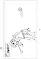
[奥側側面部の構成]
図2(b)は、入力装置奥側側面の外観構成を示す。入力装置6の筐体奥側側面の上側には、タッチパッド79が筐体上面から延設されており、筐体奥側側面の下側には、横長の発光部85が設けられる。発光部85は、赤(R)、緑(G)、青(B)のLEDを有し、クライアント端末10から送信される発光色情報にしたがって点灯する。筐体奥側側面において、上側ボタン83a、下側ボタン84aと、上側ボタン83b、下側ボタン84bとが長手方向の左右対称な位置に設けられる。上側ボタン83a、下側ボタン84aは、それぞれユーザ右手の人差し指、中指により操作され、上側ボタン83b、下側ボタン84bは、それぞれユーザ左手の人差し指、中指により操作される。図示されるように発光部85が、右側の上側ボタン83a、下側ボタン84aの並びと、左側の上側ボタン83b、下側ボタン84bの並びの間に設けられることで、各ボタンを操作する人差し指または中指によって隠れることはなく、カメラ7は、点灯した発光部85を好適に撮像することができる。上側ボタン83はプッシュ式ボタンとして構成され、下側ボタン84は回動支持されたトリガー式のボタンとして構成されてよい。
[Configuration of back side]
FIG. 2B shows an external configuration of the back side surface of the input device. A
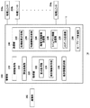
図3は、クライアント端末10の機能ブロック図を示す。クライアント端末10は、メイン電源ボタン20、電源ON用LED21、スタンバイ用LED22、システムコントローラ24、クロック26、デバイスコントローラ30、メディアドライブ32、USBモジュール34、フラッシュメモリ36、無線通信モジュール38、有線通信モジュール40、サブシステム50およびメインシステム60を有して構成される。
FIG. 3 shows a functional block diagram of the
メインシステム60は、メインCPU(Central Processing Unit)、主記憶装置であるメモリおよびメモリコントローラ、GPU(Graphics Processing Unit)などを備える。GPUはゲームプログラムの演算処理に主として利用される。これらの機能はシステムオンチップとして構成されて、1つのチップ上に形成されてよい。メインCPUはOSを起動し、OSが提供する環境下において、補助記憶装置2にインストールされたアプリケーションを実行する機能をもつ。またクラウドコンピューティングシステムとして構成されるゲームシステム1においては、メインCPUは、サーバシステム5から提供されるアプリケーション画像およびアプリケーション音声を出力装置4から出力する機能ももつ。
The
サブシステム50は、サブCPU、主記憶装置であるメモリおよびメモリコントローラなどを備え、GPUを備えない。サブCPUの回路ゲート数は、メインCPUの回路ゲート数よりも少なく、サブCPUの動作消費電力は、メインCPUの動作消費電力よりも少ない。上記したように、サブCPUは、メインCPUがスタンバイ状態にある間に動作するものであり、消費電力を低く抑えるべく、その処理機能を制限されている。なおサブCPUおよびメモリは、別個のチップに形成されてもよい。
The
メイン電源ボタン20は、ユーザからの操作入力が行われる入力部であって、クライアント端末10の筐体の前面に設けられ、クライアント端末10のメインシステム60への電源供給をオンまたはオフするために操作される。以下、メイン電源がオン状態にあるとは、メインシステム60がアクティブ状態にあることを意味し、メイン電源がオフ状態にあるとは、メインシステム60がスタンバイ状態にあることを意味する。電源ON用LED21は、メイン電源ボタン20がオンされたときに点灯し、スタンバイ用LED22は、メイン電源ボタン20がオフされたときに点灯する。
The
システムコントローラ24は、ユーザによるメイン電源ボタン20の押下を検出する。メイン電源がオフ状態にあるときにメイン電源ボタン20が押下されると、システムコントローラ24は、その押下操作を「オン指示」として取得し、一方で、メイン電源がオン状態にあるときにメイン電源ボタン20が押下されると、システムコントローラ24は、その押下操作を「オフ指示」として取得する。
The
メインCPUは補助記憶装置2やROM媒体44にインストールされているゲームプログラムを実行する機能をもつ一方で、サブCPUはそのような機能をもたない。しかしながらサブCPUは補助記憶装置2にアクセスする機能を有している。サブCPUは、このような制限された処理機能のみを有して構成されており、したがってメインCPUと比較して小さい消費電力で動作できる。これらのサブCPUの機能は、メインCPUがスタンバイ状態にある際に実行される。本実施例のクライアント端末10は、メインシステム60のスタンバイ時にはサブシステム50が稼働しているため、ネットワークサービスに常時サインインした状態を維持する。
The main CPU has a function of executing a game program installed in the
クロック26はリアルタイムクロックであって、現在の日時情報を生成し、システムコントローラ24やサブシステム50およびメインシステム60に供給する。
The
デバイスコントローラ30は、サウスブリッジのようにデバイス間の情報の受け渡しを実行するLSI(Large-Scale Integrated Circuit)として構成される。図示のように、デバイスコントローラ30には、システムコントローラ24、メディアドライブ32、USBモジュール34、フラッシュメモリ36、無線通信モジュール38、有線通信モジュール40、サブシステム50およびメインシステム60などのデバイスが接続される。デバイスコントローラ30は、それぞれのデバイスの電気特性の違いやデータ転送速度の差を吸収し、データ転送のタイミングを制御する。
The
メディアドライブ32は、ゲームアプリケーションなどのソフトウェアおよびライセンス情報を記録したROM媒体44を装着して駆動し、ROM媒体44からプログラムやデータなどを読み出すドライブ装置である。ROM媒体44は、光ディスクや光磁気ディスク、ブルーレイディスクなどの読出専用の記録メディアである。
The media drive 32 is a drive device that loads and drives a
USBモジュール34は、外部機器とUSBケーブルで接続するモジュールである。USBモジュール34は補助記憶装置2およびカメラ7とUSBケーブルで接続してもよい。フラッシュメモリ36は、内部ストレージを構成する補助記憶装置である。無線通信モジュール38は、Bluetooth(登録商標)プロトコルやIEEE802.11プロトコルなどの通信プロトコルで、たとえば入力装置6と無線通信する。なお無線通信モジュール38は、ITU(International Telecommunication Union;国際電気通信連合)によって定められたIMT−2000(International Mobile Telecommunication 2000)規格に準拠した第3世代(3rd Generation)デジタル携帯電話方式に対応してもよく、さらには別の世代のデジタル携帯電話方式に対応してもよい。有線通信モジュール40は、外部機器と有線通信し、たとえばAP8を介してネットワーク3に接続する。
The
まず最初に、クライアント端末10の構成について説明する。
図4は、クライアント端末10の構成を示す。クライアント端末10は、処理部100および通信部102を備え、処理部100は、受付部110、送信部120、取得部130、アイコン表示部132、通知部134、アプリケーション実行部136、出力処理部138、監視部140およびセーブデータ管理部150を備える。送信部120は、要求送信部122、操作情報送信部124および待機解除情報送信部126を備える。通信部102は図3に示す無線通信モジュール38および有線通信モジュール40の機能を併せ持つ構成として表現している。
First, the configuration of the
FIG. 4 shows the configuration of the
図4において、さまざまな処理を行う機能ブロックとして記載される各要素は、ハードウェア的には、回路ブロック、メモリ、その他のLSIで構成することができ、ソフトウェア的には、メモリにロードされたプログラムなどによって実現される。したがって、これらの機能ブロックがハードウェアのみ、ソフトウェアのみ、またはそれらの組合せによっていろいろな形で実現できることは当業者には理解されるところであり、いずれかに限定されるものではない。 In FIG. 4, each element described as a functional block for performing various processes can be configured by a circuit block, a memory, and other LSIs in terms of hardware, and loaded into the memory in terms of software. Realized by programs. Therefore, it is understood by those skilled in the art that these functional blocks can be realized in various forms by hardware only, software only, or a combination thereof, and is not limited to any one.
受付部110は、通信部102を介して入力装置6の操作情報を受け付け、クラウドゲームを開始する際には、サーバシステム5におけるアプリケーションの実行要求を受け付ける。送信部120は、通信部102を介してサーバシステム5に対して、アプリケーションの実行要求や、入力装置6の操作情報などを送信する。取得部130は、通信部102を介してサーバシステム5から、アプリケーションの処理結果や、各種情報、各種データを取得する。アイコン表示部132は、ホーム画面において、アプリケーションのアイコン画像を並べて表示する。通知部134は、ゲームに関する通知、特にサーバシステム5から送信されるクラウドゲームに関する通知を表示する。なお通知部134は、ゲームに関する通知を音声出力してもよい。アプリケーション実行部136は、補助記憶装置2に保持されたアプリケーションプログラムまたはROM媒体44に記録されているアプリケーションプログラムを実行する機能を有し、ここではアプリケーションプログラムにより実現される機能を含むものとして表現している。出力処理部138は、アプリケーション画像およびアプリケーション音声を出力装置4に出力する。監視部140は、クライアント端末10の稼働状況を監視し、具体的には入力装置6における入力の有無を監視する。監視部140は、入力装置6からの入力がない期間(無操作期間)を計測する機能をもつ。セーブデータ管理部150は、第1ストレージシステム18および/または第2ストレージシステム19との間で、セーブデータのアップロードまたはダウンロードを行うセーブデータ管理機能を有する。
The
次に、クラウドサーバ14の構成について説明する。
図5は、クラウドサーバ14の構成を示す。なお本実施例では、サーバシステム5がストアサーバ12およびクラウドサーバ14を含むものとして説明するが、ストアサーバ12およびクラウドサーバ14は、それぞれの機能を集約した単一のサーバとして構成されてもよい。したがって図5に示すクラウドサーバ14の構成は、その一部または全部をストアサーバ12が備えてもよく、図示しないストアサーバ12の構成の一部または全部をクラウドサーバ14が備えてもよい。以下、説明の便宜上、ストアサーバ12が、ユーザがクラウドゲームをプレイするための入口としての役割をもち、クラウドサーバ14が、ユーザにクラウドゲームを提供する役割をもつこととするが、以下で説明するクラウドサーバ14の構成は、少なくともサーバシステム5に備えられていればよいのであって、以下の説明は、ストアサーバ12とクラウドサーバ14との機能を明確に区別することを目的とするものではない。
Next, the configuration of the
FIG. 5 shows the configuration of the
クラウドサーバ14は、管理部200、通信部202と、複数の処理ユニット204a、204b、・・・204z(以下、総称する場合には「処理ユニット204」と呼ぶ)を備える。複数の処理ユニット204は、データベース16に格納されているアプリケーションのディスクイメージを読み出して、アプリケーションプログラムを実行する機能を有する。クラウドサーバ14は、たとえば10000個の処理ユニット204を備え、10000人のユーザのクライアント端末10に、処理ユニット204を割り当てる機能をもつ。処理ユニット204は、ゲームアプリケーションを処理し、その処理結果であるゲーム画像およびゲーム音声を生成する。通信部202はネットワーク3を介してクライアント端末10の通信部102との間でデータを送受信する。
The
管理部200は、稼働監視部210、割当処理部212、取得部220、操作情報提供部230、送信部240およびセーブデータ管理部260を備える。取得部220は、要求取得部222および操作情報取得部224を備え、送信部240は、処理結果送信部242、待機情報送信部244、処理可能情報送信部246、タイムアウト情報送信部248およびメタデータ送信部250を備える。
The
図5において、さまざまな処理を行う機能ブロックとして記載される各要素は、ハードウェア的には、回路ブロック、メモリ、その他のLSIで構成することができ、ソフトウェア的には、メモリにロードされたプログラムなどによって実現される。したがって、これらの機能ブロックがハードウェアのみ、ソフトウェアのみ、またはそれらの組合せによっていろいろな形で実現できることは当業者には理解されるところであり、いずれかに限定されるものではない。なお既述したように、図5に示す構成は、サーバシステム5において備えられていればよく、したがってストアサーバ12が、図5に示す構成を有していてもよい。
In FIG. 5, each element described as a functional block for performing various processes can be configured by a circuit block, a memory, and other LSIs in terms of hardware, and loaded in the memory in terms of software. Realized by programs. Therefore, it is understood by those skilled in the art that these functional blocks can be realized in various forms by hardware only, software only, or a combination thereof, and is not limited to any one. As described above, the configuration shown in FIG. 5 only needs to be provided in the
稼働監視部210は、複数の処理ユニット204の稼働状況とともに、処理ユニット204を割り当てられたクライアント端末10の稼働状況を監視する。稼働監視部210は、複数の処理ユニット204の稼働状況を監視することで、クラウドサービスの提供を希望するユーザに割当可能な処理ユニット204、すなわちユーザが利用可能な処理ユニット204が存在するか否かを把握する。また稼働監視部210は、クラウドサービスの提供を受けているユーザのクライアント端末10から、操作情報が送信されているか否かを監視する。処理ユニット204の数は有限であるため、所定時間、操作情報が入力されないクライアント端末10に対しては、割り当てた処理ユニット204を解放して、別の待機ユーザに割り当てる方が好ましいためである。このように稼働監視部210は、処理ユニット204の空きの有無や、クライアント端末10における無操作期間を監視して、処理ユニット204をユーザに割り当てる割当処理部212の動作を効果的に支援する。なおクライアント端末10の稼働状況は、監視部140によりクライアント端末10側で監視されてもよい。
The
割当処理部212は、クライアント端末10に対して、処理ユニット204を割り当てる処理を行う。たとえば割当処理部212は、処理ユニット204の識別情報(ID)と、処理ユニット204を割り当てられたクライアント端末10(またはユーザ)の識別情報とを対応付けて、テーブル形式で管理してもよい。また割当処理部212は、ユーザに割当可能な処理ユニット204が存在しない場合には、クライアント端末10にアプリケーションの処理の開始を待機させて、そのユーザを待機ユーザとして管理する。割当可能な処理ユニット204が生じた場合には、稼働監視部210から、その旨の通知を受け、この通知にしたがって、割当処理部212は、待機ユーザのクライアント端末10に対して、割当可能となった処理ユニット204を割り当てる処理を行う。
The
取得部220は、通信部202を介してクライアント端末10から、アプリケーションの実行要求や、入力装置6の操作情報を取得する。要求取得部222が、ユーザからアプリケーションの実行要求を取得すると、稼働監視部210の監視により、割当可能な処理ユニット204が存在すれば、割当処理部212が、その処理ユニット204をユーザが利用するように割り当て、要求されたアプリケーションを実行させる。一方で、稼働監視部210の監視により、割当可能な処理ユニット204が存在しなければ、割当処理部212は、当該ユーザを待機ユーザとして待ち行列(キュー)に入れて管理する。操作情報取得部224は、処理ユニット204を割り当てられたユーザから操作情報を取得し、操作情報提供部230は、処理ユニット204に、クライアント端末10から送信された入力装置6の操作情報を提供する。これにより処理ユニット204は、操作情報をアプリケーションの進行に反映した処理結果を生成する。
The
送信部240は、処理ユニット204で生成されたゲーム画像およびゲーム音声や、各種情報、各種データをクライアント端末10に送信する。セーブデータ管理部260は、クライアント端末10との間で、セーブデータを管理する機能を有する。
The
以下、表示画面をもとに、クライアント端末10に表示されるUI(ユーザインタフェース)について説明する。ユーザ「TARO」がクライアント端末10にログインすると、ホーム画面が表示される。
図6は、クライアント端末10のシステムソフトウェアが生成するホーム画面の一例を示す。
Hereinafter, a UI (user interface) displayed on the
FIG. 6 shows an example of a home screen generated by the system software of the
ホーム画面において、アイコン表示部132は、アイコン列302に、複数のアプリケーションのアイコン画像を並べて表示する。図6に示すホーム画面においては、アプリケーション実行部136により処理可能なアプリケーションのアイコン画像が並べて表示されている。アイコン列302の先頭(すなわち左端)にはフォーカス枠304が設けられ、フォーカス枠304に配置されるアイコン画像は、他のアイコン画像よりも大きく表示される。ここではゲーム「プレイゴルフ」のアイコン画像がフォーカス枠304に配置されている。ユーザは、実行したいアプリケーションのアイコン画像をフォーカス枠304に配置し、入力装置6の決定ボタン(たとえば○ボタン72)を操作すると、そのアイコン画像に対応付けられたゲーム「プレイゴルフ」のプログラムが補助記憶装置2またはROM媒体44から読み出されて起動される。
On the home screen, the
またホーム画面には、クライアント端末10が提供するシステム機能を示す複数の機能アイコン306が表示される。図6の例では、アイコン表示部132が、ストアアイコン306a、通知アイコン306b、フレンドアイコン306c、プロフィールアイコン306f、トロフィーアイコン306gを表示する。図6に示すホーム画面においてユーザがストアアイコン306aを選択して決定操作すると、システムソフトウェアが、ストアアイコン306aに関するファンクション画面を出力装置4に表示する。
A plurality of
図7は、ホーム画面から遷移したファンクション画面の一例を示す。
ファンクション画面において、アイコン表示部132は、複数の機能アイコン306を並べて配置する。ここではストアアイコン306a、通知アイコン306b、フレンドアイコン306c、グループメッセージアイコン306d、パーティーアイコン306e、プロフィールアイコン306f、トロフィーアイコン306g、設定アイコン306h、電源アイコン306iが表示されている。システムソフトウェアは、ユーザによる入力装置6の横方向(方向キー71の左キーまたは右キー)の操作入力に応じて、フォーカスさせる機能アイコン306を順次切り替え、フォーカスアイコンを強調した態様(大きいサイズ、異なる色等)で表示する。図7では、ストアアイコン306aが選択されてフォーカスされ、他のアイコンより強調表示された状態を示している。
FIG. 7 shows an example of a function screen transitioned from the home screen.
On the function screen, the
ファンクション画面において、ユーザが、フォーカスされたストアアイコン306aを決定操作すると、クライアント端末10は、ストアサーバ12にアクセスし、出力装置4にはストア画面が表示される。このストア画面でユーザは、ダウンロードしてクライアント端末10で処理するゲーム(ダウンロードゲーム)や、クラウドサーバ14にて処理されるゲーム(クラウドゲーム)など、様々なコンテンツを選択できる。ユーザが、ストア画面においてクラウドゲームを選択すると、当該ゲームのレンタル画面が出力装置4に表示される。
When the user determines and operates the
図8は、レンタル画面の一例を示す。このレンタル画面は、ユーザがクラウドゲーム「WARSHIP2」を所定期間レンタルして、クラウドサーバ14にアクセスする入口となる画面である。このように本実施例のゲームシステム1では、ユーザが、ストアサーバ12にてクラウドゲームを所定期間(たとえば1ヶ月)レンタルすることで、1ヶ月分のライセンスを取得でき、その期間、クラウドゲームをプレイできる仕組みが構築されている。なお、これはクラウドゲームの提供形態の一例であり、ユーザは、ストアサーバ12においてクラウドゲームを買い切りの形態で購入して、永久的なライセンスを取得できるようにしてもよい。
FIG. 8 shows an example of a rental screen. This rental screen is a screen that serves as an entrance for the user to rent the cloud game “WARSHIP2” for a predetermined period and access the
このレンタル画面において、ユーザが、フォーカス枠320を「レンタルしてはじめる」ボタンに合わせ、入力装置6の決定ボタンを操作すると、ストアサーバ12は、ユーザに「WARSHIP2」をプレイするためのライセンスを付与するとともに、クライアント端末10に対して、「WARSHIP2」のタイトル名、アイコン画像、パレンタルコントロール情報などのアプリケーションのメタデータを送信する。なお後述するように、メタデータは、クラウドサーバ14からクライアント端末10に送信されてもよく、ストアサーバ12は、タイトル名、アイコン画像、パレンタルコントロール情報の一部のみをクライアント端末10に送信してもよい。
In this rental screen, when the user moves the
ストアサーバ12は、レンタル画面においてユーザが「レンタルしてはじめる」ボタンを押下すると、クラウドサーバ14に、このユーザが「WARSHIP2」のライセンスを有していることを通知するとともに、「WARSHIP2」の実行要求を送信する。クラウドサーバ14において要求取得部222が実行要求を取得すると、メタデータ送信部250は、クライアント端末10に対して、「WARSHIP2」のタイトル名、アイコン画像、パレンタルコントロール情報などのアプリケーションのメタデータをクライアント端末10に送信する。これらのメタデータは、クライアント端末10のホーム画面に表示されるために送信され、クライアント端末10における取得部130により取得される。その後、クラウドサーバ14は、ユーザが適正なライセンスを有しているかの確認と、クライアント端末10との間の通信環境の確認を行う。なお、これらの確認は、引き続きストアサーバ12によって行われてもよい。
When the user presses the “Rental Start” button on the rental screen, the
なおユーザが「レンタルしてはじめる」ボタンを押下したとき、クライアント端末10において、クラウドゲームをプレイさせるための専用のアプリケーション(以下、「プレイヤアプリ」と呼ぶこともある)が自動起動されてよい。プレイヤアプリは、たとえば監視部140の機能を実現して、クライアント端末10における無操作期間を測定してもよい。
When the user presses the “rental start” button, a dedicated application for playing a cloud game (hereinafter also referred to as “player application”) may be automatically started on the
図9は、クラウドサーバ14によるユーザ認証中に表示される通知画面の例を示す。出力装置4に図9に示す通知画面が表示されている間、クラウドサーバ14は、ユーザが「WARSHIP2」のライセンス情報を有しているか否かを確認する。
図10は、クラウドサーバ14による通信環境のチェック中に表示される通知画面の例を示す。出力装置4に図10に示す通知画面が表示されている間、クラウドサーバ14は、ユーザのクライアント端末10とクラウドサーバ14との間の通信環境をチェックする。ここでは、クラウドサーバ14は、通信帯域幅やレイテンシをチェックし、クラウドゲームを実行可能な通信環境であるか否かを確認する。
なお、この通知画面においては、図示されるように、クラウドゲームが、5分間の無操作期間があると、自動終了する旨が表示される。これは、限りある計算リソース(処理ユニット204)を効率的に稼働させるためのポリシーに基づくものであり、無操作期間の上限は5分に限られるものではない。クラウドサーバ14は、接続確認中に、この無操作期間に関する説明をユーザに通知するようにする。
以下、これらの確認により、問題がなかったときのUIについて説明する。
FIG. 9 shows an example of a notification screen displayed during user authentication by the
FIG. 10 shows an example of a notification screen displayed during the check of the communication environment by the
In this notification screen, as shown in the figure, when the cloud game has a no-operation period of 5 minutes, it is displayed that it is automatically terminated. This is based on a policy for efficiently operating a limited computing resource (processing unit 204), and the upper limit of the no-operation period is not limited to 5 minutes. The
Hereinafter, the UI when there is no problem by these confirmations will be described.
図5に戻り、クラウドサーバ14において、要求取得部222が、通信部202を介してストアサーバ12から実行要求を受け取ると、割当処理部212が、このユーザに1つの処理ユニット204を割り当てる。稼働監視部210は、複数の処理ユニット204の稼働状況を監視しており、したがって、空いている処理ユニット204が存在するか否か、すなわち割当可能な処理ユニット204が存在するか否かを把握している。割当可能な処理ユニット204が存在する場合、既述したように割当処理部212は、ユーザに、処理ユニット204を割り当て、その処理ユニット204に、アプリケーション(この場合はゲーム「WARSHIP2」)の実行要求を伝える。処理ユニット204は、データベース16から、当該アプリケーションのディスクイメージを読み出し、当該アプリケーションを起動する。
Returning to FIG. 5, when the
クライアント端末10において、出力処理部138は、通信部102を介して、処理ユニット204の処理結果を取得し、出力装置4に出力再生する。ユーザが入力装置6を操作すると、その操作情報は受付部110により受け付けられ、操作情報送信部124が、通信部102を介してクラウドサーバ14に操作情報を送信する。クラウドサーバ14において、操作情報取得部224が、操作情報を取得し、操作情報提供部230が、ユーザに割り当てられた処理ユニット204に操作情報を提供する。処理ユニット204は、提供された操作情報をもとに、ゲームプログラムを実行し、処理結果送信部242が、その処理結果をエンコードして、クライアント端末10に送信する。このように本実施例のゲームシステム1では、アプリケーションが、クラウドサーバ14の計算リソース(処理ユニット204)により処理されて、その処理結果がクライアント端末10に提供されることで、クライアント端末10が、アプリケーションプログラムを保持していなくても、ユーザがアプリケーションを楽しむことができる。
In the
一方、要求取得部222が、通信部202を介してストアサーバ12からアプリケーションの実行要求を受け取った時点で、稼働監視部210による複数の処理ユニット204の稼働状況の監視の結果、割当可能な処理ユニット204が存在していないことがある。たとえばクラウドサーバ14が10000個の処理ユニット204を有しており、その全てがユーザに既に割り当てられて使用中であれば、稼働監視部210は、割当可能な処理ユニット204が存在しないことを把握している。仮に、空いている処理ユニット204が存在している場合であっても、その処理ユニット204が特定のユーザ(たとえばプレミアムユーザ)に割り当てられるものであり、「WARSHIP2」のプレイを希望するユーザ「TARO」がプレミアムユーザでなければ、稼働監視部210は、当該ユーザが利用可能な処理ユニット204が存在しないことが分かる。
On the other hand, when the
割当可能な処理ユニット204が存在しない場合、ユーザは、自身が利用可能な処理ユニット204が解放されて、自身に処理ユニット204が割り当てられ、アプリケーションが開始されるまで、待機状態に入る。割当処理部212は、待機状態にあるユーザを、その順番とともに管理する。具体的に割当処理部212は、ユーザを特定する情報(ユーザID)と、待機の順番とを対応付けて記憶する。待機情報送信部244は、その時点における待機人数を示す情報をクライアント端末10に送信する。
If there is no assignable processing unit 204, the user enters a waiting state until the processing unit 204 available to him is released, the processing unit 204 is assigned to him and the application is started. The
図11は、待機人数を通知する通知画面の例を示す。この通知画面では、当該ユーザの前に、2人のユーザが待機していることが通知されている。待機情報送信部244は、割当処理部212から、既に待機しているユーザの人数を受け取り、待機情報としてクライアント端末10に送信する。クライアント端末10において、通知部134は、送信された待機人数を出力装置4に表示する。ユーザがフォーカス枠322を「OK」に合わせて出力装置4の決定ボタンを操作すると、要求送信部122が、待機を了承したことを示す情報(待機要求)をクラウドサーバ14に送信する。要求取得部222が、待機要求を取得すると、割当処理部212が、当該ユーザのユーザIDと、待機順番(この例では3番目)とを対応付けて管理する。
FIG. 11 shows an example of a notification screen for notifying the number of waiting persons. In this notification screen, it is notified that two users are waiting before the user. The standby
なお、ここでは待機情報送信部244が待機情報として待機人数を送信することを説明したが、たとえば割当処理部212は、待機人数から、ユーザ「TARO」がゲームプレイできるまでの時間を予測して、待機情報送信部244が、待機予測時間を待機情報としてクライアント端末10に送信してもよい。この場合は、クライアント端末10において、待機予測時間が、通知画面に表示されることになる。このように待機情報送信部244は、アプリケーション処理の待機に関する情報をクライアント端末10に送信し、クライアント端末10は、送信された待機に関する情報を出力装置4に表示することができる。
Here, it has been described that the waiting
図11に示す通知画面において、ユーザが「OK」ボタンを押すと、レンタル画面に戻る。図12は、図11に示す通知画面から戻ったレンタル画面を示すが、ここでは、このユーザ「TARO」が、「待機中」であって、且つ待機の順番が「3番目」であることが示されている。このレンタル画面は、ストアサーバ12から提供されるが、サーバシステム5において、クラウドサーバ14から、ユーザが待機中であること、および3番目の待機であることがストアサーバ12に通知されることで、レンタル画面においても待機の順番が表示されることになる。なお稼働監視部210および割当処理部212の機能がストアサーバ12に設けられている場合には、ストアサーバ12が、ユーザ「TARO」の待機を管理することになるため、ストアサーバ12は、クラウドサーバ14から待機連絡をもらう必要はない。レンタル画面が出力装置4に表示されている状態で、ユーザが入力装置6のホームボタン80を操作すると、出力装置4にはホーム画面が表示される。
When the user presses the “OK” button on the notification screen shown in FIG. 11, the screen returns to the rental screen. FIG. 12 shows the rental screen returned from the notification screen shown in FIG. 11. Here, it is assumed that the user “TARO” is “waiting” and the waiting order is “third”. It is shown. This rental screen is provided from the
図13は、ホーム画面の別の例を示す。ホーム画面において、アイコン表示部132は、アイコン列302に、複数のアプリケーションのアイコン画像を並べて表示する。ここでフォーカス枠304に表示されているアイコン画像は、ユーザがストアサーバ12においてライセンスを取得したクラウドゲームのアイコン画像(クラウドゲームアイコン330)である。このクラウドゲームアイコン330に対応するゲームプログラムは、クライアント端末10に保持されておらず、したがってクラウドゲームアイコン330は、クラウドサーバ14におけるクラウドゲームの提供を受けるための、いわばショートカットとして利用される。
FIG. 13 shows another example of the home screen. On the home screen, the
このようにアイコン表示部132は、アプリケーション実行部136により処理可能なアプリケーションのアイコン画像とともに、サーバシステム5により処理可能なアプリケーションのアイコン画像(クラウドゲームアイコン330)とを、並べて表示する。これによりユーザは、クライアント端末10で処理されるゲームと、クラウドサーバ14で処理されるゲームとを、1つのホーム画面中で確認できるようになる。
In this way, the
アイコン表示部132は、クラウドゲームアイコン330に関連付けて、クラウドゲームであることを示すクラウドカテゴリアイコン336と、タイトル情報338とを表示する。クラウドカテゴリアイコン336を表示することで、ユーザは、当該ゲームがクラウドゲームであることを認識できる。
The
またアイコン表示部132は、処理の開始を待機しているクラウドゲームアイコン330に関連付けて、待機に関する情報、すなわち現在のステータスが待機中であることを示す待機インジケータ332と、ユーザが何番目の待機であるかを示す順番情報334とを付加して表示する。これによりユーザは、現在自身が待機中であること、および待機順番が3番目であることを認識できる。
In addition, the
図13では、ユーザがクラウドゲームの待機中であるときに、アイコン表示部132が、クラウドゲームアイコン330に待機情報を関連付けて表示する。アイコン表示部132は、待機中以外においても、様々な情報をクラウドゲームアイコン330に付加する。以下、クラウドゲームアイコン330に関連付けて表示される情報の別の例を示す。
In FIG. 13, when the user is waiting for the cloud game, the
図14(a)は、ショートカットとして利用されるクラウドゲームアイコン330の表示例を示す。クラウドゲームアイコン330には、クラウドカテゴリアイコン336が関連付けて表示されている。クラウドゲームアイコン330がフォーカス枠304に配置されている状態で、ユーザが入力装置6の決定ボタンを操作すると、受付部110が、アプリケーションの実行要求を受け付け、要求送信部122が、実行要求をサーバシステム5に送信する。実行要求はストアサーバ12によって取得され、クラウドサーバ14に転送されてもよいが、クラウドサーバ14によって直接取得されてもよい。クラウドサーバ14において、要求取得部222がアプリケーションの実行要求を受け付けると、既述したように、クラウドサーバ14は、ユーザが適正なライセンスを有しているかの確認と、クライアント端末10との間の通信環境の確認を行い、その後、割当可能な処理ユニット204が存在していれば、処理ユニット204が、アプリケーションを処理して、処理結果送信部242が、その処理結果をクライアント端末10に送信する。このように、図14(a)に示すクラウドゲームアイコン330は、クラウドゲームのショートカットとして利用できる。
FIG. 14A shows a display example of a
図14(b)は、クラウドゲームアイコン330の別の表示例を示す。このクラウドゲームアイコン330には、クラウドカテゴリアイコン336とともに、アプリケーションが実行中であることを示す実行インジケータ340が関連付けて表示されている。クラウドサーバ14からアプリケーションの処理結果を提供されている最中に、ユーザがホーム画面に戻ったときには、クラウドゲームアイコン330に、実行インジケータ340が付加されて表示される。これによりユーザは、クラウドゲームをプレイ中であることを確認できる。なおユーザは、実行インジケータ340が付加されたクラウドゲームアイコン330を決定操作することで、直接、クラウドサーバ14から提供されているゲーム画面に復帰することができる。
FIG. 14B shows another display example of the
図14(c)は、クラウドゲームアイコン330の別の表示例を示す。このクラウドゲームアイコン330には、クラウドカテゴリアイコン336ではなく、現在、このクラウドゲームをプレイできないことを示す鍵アイコン342が関連付けて表示されている。たとえばライセンスが失効しているような場合や、パレンタルコントロール情報によってアプリケーションの利用が制限される場合に、この鍵アイコン342が表示される。ライセンスが失効している場合、ユーザがクラウドゲームアイコン330を選択操作すると、ストアサーバ12が、ライセンスの購入画面を提供し、ユーザは、ライセンスを取得することで、クラウドゲームサービスの提供を受けられるようになる。
FIG. 14C shows another display example of the
本実施例のクライアント端末10は、同時に複数のアプリケーションを実行する機能を有している。ユーザは、クラウドゲームサービスの待機中、図13に示すホーム画面を出力装置4に表示した後、アイコン列302に並べられている1つ以上のアプリケーションを楽しむことができる。
The
図13に示すホーム画面において、ユーザがアイコン列302を左に1つ動かすと、図6に示したアイコン列302が表示される。ゲーム「プレイゴルフ」のアイコン画像がフォーカス枠304に配置された状態で、ユーザが入力装置6の決定ボタンを操作すると、クライアント端末10において、アプリケーション実行部136が、ゲーム「プレイゴルフ」の処理を開始する。このゲームは、補助記憶装置2にインストールされており、アプリケーション実行部136は、補助記憶装置2からプログラムを読み出して、「プレイゴルフ」を起動する。なおゲームプログラムは、ROM媒体44から読み出されてもよい。
When the user moves the
図15は、ローカルアプリケーションの実行画面の一例を示す。受付部110は、ユーザの入力装置6の入力、すなわち操作情報を受け付け、アプリケーション実行部136は、操作情報をアプリケーションの処理に反映して、アプリケーション画面およびアプリケーション音声を生成する。出力処理部138は、生成された画面および音声を出力装置4から出力する。このようにアプリケーション実行部136は、サーバシステム5におけるクラウドゲームの処理の開始を待機した状態で、別のアプリケーションの処理を開始することができる。なお、ここで別のアプリケーションとは、特定の種類のアプリケーション、たとえばゲームアプリケーションを意味し、プレイヤアプリケーションなどは含まない。これによりユーザは、待機中、ただ順番がくるのを待つのではなく、クライアント端末10に保持されているゲームを楽しむことができる。
FIG. 15 shows an example of a local application execution screen. The receiving
クラウドサーバ14において、割当処理部212は、クラウドサービスを待機しているユーザのユーザIDと、その順番とを管理している。稼働監視部210は、処理ユニット204の稼働状況を監視しており、処理ユニット204が解放されて、少なくとも1つの処理ユニット204が待機ユーザに対して割当可能になると、割当可能となった処理ユニット204のID(ユニットID)を割当処理部212に通知する。処理ユニット204が解放される場合とは、ゲームを終了する場合であって、プレイしているユーザが、ゲームを自発的に終了する場合や、後述するように、ユーザの無操作期間が所定時間を超えたときに、強制的にゲームを終了する場合を含む。処理ユニット204が割当可能になると、割当処理部212は、待機順番が1番のユーザに、その処理ユニットを割り当てる。このように割当処理部212は、ユーザと処理ユニット204の割り当てを管理している。
In the
上記した例では、ユーザ「TARO」の前に2人のユーザが既に待機しており、したがってユーザ「TARO」は、クラウドサーバ14に待機要求を送信した時点では、3番目の待機ユーザとして、割当処理部212において管理されている。割当処理部212が、1番目の待機ユーザに処理ユニット204を割り当てると、待機情報送信部244は、割当処理部212から、ユーザ「TARO」の待機順番が2番目になったことを通知され、その旨をクライアント端末10に送信する。これにより出力装置4にホーム画面が表示される際には、クラウドゲームアイコン330に関連付けて、待機順番が2番目になったことが表示される。また、さらに1つの処理ユニット204が割当可能になると、割当処理部212は、待機順番が1番のユーザに、その処理ユニットを割り当てる。このときユーザ「TARO」の順番は、次になる。待機情報送信部244は、待機順番が1番となったユーザ「TARO」に対して、次の順番であることを示す情報を送信する。
In the above example, two users are already waiting before the user “TARO”, and therefore the user “TARO” is assigned as the third waiting user when the standby request is transmitted to the
図16は、ローカルアプリケーションの処理画面に表示される予告情報を示す。通知部134は、まもなく順番が来ることを示す予告情報350を、アプリケーション画面に重畳して表示する。ユーザは、この予告情報350を見て、もうすぐ自分がクラウドゲームをプレイできることを認識する。
FIG. 16 shows notice information displayed on the processing screen of the local application. The
クラウドサーバ14において、さらに1つの処理ユニット204が利用可能となり、ユーザ「TARO」に対して処理ユニット204が割当可能となると、処理可能情報送信部246は、クライアント端末10に、アプリケーションの処理を開始できることを示す情報を送信する。クライアント端末10において、取得部130が、クラウドサーバ14から、アプリケーションの処理を開始できることを示す情報を取得すると、通知部134が、アプリケーションの処理が開始されることをユーザに通知する。
When one more processing unit 204 becomes available in the
図17は、クラウドサーバ14におけるアプリケーションの開始を通知する開始通知情報を示す。通知部134は、ユーザの順番が来たことを示す開始通知情報352を、アプリケーション画面に重畳して表示する。ユーザは、この開始通知情報352を見て、自分の順番が来たことを認識する。ここでユーザが、入力装置6のホームボタン80を操作するか、または開始通知情報352の表示後15秒が経過した後に、クラウドゲームの起動画面が出力装置4に表示される。
FIG. 17 shows start notification information for notifying the start of an application in the
図18は、クラウドゲームの起動画面の例を示す。この起動画面においては、サーバシステム5におけるアプリケーションの処理を開始するかを問い合わせる選択肢が表示される。具体的には、取得部130が、クラウドサーバ14から、クラウドゲームの処理が開始できることを示す情報を取得すると、通知部134は、アプリケーション画面に開始通知情報352を表示した後、クラウドゲームの処理を開始するか否かを問い合わせる起動画面を出力装置4に表示する。後述するように、この起動画面は、アプリケーション実行部136においてゲームアプリケーションなどの所定の種類のアプリケーションが処理されている場合に表示され、通知部134は、所定の種類のアプリケーションが処理されている場合に、起動画面を出力装置4に表示する。なお通知部134は、クラウドサーバ14に対して、起動画面においてゲームの開始要求が生成されるまで、クラウドゲームの開始を待つように指示してもよい。図18に示す起動画面には、「ゲームを始める」、「キャンセル」の2つのボタンが表示され、ユーザは、フォーカス枠360を動かして、いずれかを選択する。
FIG. 18 shows an example of a cloud game startup screen. On this startup screen, an option for inquiring whether to start application processing in the
ユーザがクラウドゲームを開始する場合、フォーカス枠360を「ゲームを始める」に合わせて、入力装置6の決定ボタン(○ボタン72)を操作する。受付部110は、このボタン操作を、クラウドゲームの開始要求として受け付け、要求送信部122は、クラウドサーバ14に開始要求を送信する。なお、アプリケーション実行部136がアプリケーションの処理を行っている場合に、サーバシステム5におけるクラウドゲームを始めることを選択すると、アプリケーション実行部136による処理は一時中断する。したがって、この場合、通知部134は、ユーザに、実行中の所定のアプリケーションが一時中断されることを通知する。
When the user starts a cloud game, the
図19は、実行中アプリケーション中断の通知画面の例を示す。この通知画面においては、クラウドゲームが開始されることにともなって中断されるアプリケーションのタイトルが表示される。上記の例では、アプリケーション実行部136がゲーム「プレイゴルフ」を処理しており、したがって、このゲームが一時中断されることが通知される。この通知画面の表示後、通知部134は、クラウドゲームが始まることを示す通知を表示する。クラウドサーバ14において、要求取得部222がゲームの開始要求を取得すると、割当処理部212は、ユーザ「TARO」に処理ユニット204を割り当て、その処理ユニット204に、実行要求により特定されるゲームアプリケーションの処理を開始させる。ユーザ「TARO」に割り当てられた処理ユニット204は、ゲーム「WARSHIP2」のプログラムをデータベース16から読み出し、処理を開始する。
FIG. 19 shows an example of a notification screen for interrupting an executing application. On the notification screen, the title of the application that is interrupted when the cloud game is started is displayed. In the above example, the
図20は、処理ユニット204により生成されるゲーム画像の一例を示す。処理ユニット204が、アプリケーションを処理すると、処理結果送信部242が、その処理結果をエンコードしてクライアント端末10にストリーミング配信する。クライアント端末10において出力処理部138は、処理ユニット204により生成されたゲーム画像を出力装置4から出力する。
FIG. 20 shows an example of a game image generated by the processing unit 204. When the processing unit 204 processes the application, the processing
なお、上記した例では、アプリケーション実行部136によるアプリケーションの処理中に、自分の順番が来たことを説明したが、アプリケーション実行部136によるアプリケーション処理が行われていない場合に、自分の順番が来ることもある。たとえば、ユーザがアプリケーションを行わず、出力装置4にはホーム画面が表示されているような場合である。この場合には、取得部130が、クラウドサーバ14から、アプリケーションの処理を開始する情報を取得すると、通知部134が、ホーム画面上に、図17に示す開始通知情報352を表示し、その後、クラウドゲームの起動画面を表示することなく、ただちにクラウドゲームが起動されてもよい。アプリケーション実行部136による所定の種類のアプリケーション処理が行われていない場合には、通知部134がクラウドサーバ14に対して、ゲームの開始要求が生成されるまでクラウドゲームの開始を待つことを指示しないため、クラウドサーバ14は、ユーザからの開始要求を待つことなく、クラウドゲームを自動的に起動する。このようにアプリケーション実行部136により所定のアプリケーションの処理が行われていなければ、一時中断するアプリケーションが存在しないため、割当処理部212は処理ユニット204に、ゲームアプリケーションの処理の開始をすみやかに指示して、処理ユニット204に、ゲームアプリケーションの処理を開始させることが好ましい。そのためクライアント端末10において所定の種類のアプリケーション以外のアプリケーション、たとえばブラウザなどが起動されていても、ブラウザを一時中断することなく、クラウドサーバ14は、クラウドゲームを自動的に起動してよい。
In the above example, it has been described that the turn of the application has been performed during the processing of the application by the
図21は、クラウドゲームの起動画面の例を示す。図18との違いは、フォーカス枠360が、「キャンセル」に配置されている点である。ユーザがクラウドゲームを開始せず、ローカルで実行中のアプリケーションを継続する場合、フォーカス枠360を「キャンセル」に合わせて、入力装置6の決定ボタン(○ボタン72)を操作する。この操作情報はキャンセル要求として要求送信部122よりクラウドサーバ14に送信される。クラウドサーバ14において要求取得部222がキャンセル要求を取得すると、割当処理部212が、ユーザ「TARO」の待機状態を解除して、処理ユニット204の割り当て処理を終了する。これにより割当処理部212は、ユーザ「TARO」への処理ユニット204の割り当て処理を終了し、TAROの次以降の順番で待機していた別のユーザへの割り当て処理を開始する。なお、要求取得部222がキャンセル要求を取得すると、割当処理部212が、待機状態を解除するのではなく、たとえば所定の順番(たとえば5番目)に繰り下げて待機状態を維持してもよい。
FIG. 21 shows an example of a boot screen for a cloud game. A difference from FIG. 18 is that the
図22は、クラウドゲーム待機のキャンセルを通知する通知画面の例を示す。この通知画面でユーザが入力装置6の決定ボタンを操作すると、出力処理部138は、アプリケーション実行部136による処理結果、つまり「プレイゴルフ」のゲーム画像を出力装置4から出力する。なお、このとき、クラウドサーバ14におけるユーザ「TARO」の待機状態は解除されているため、このユーザが、再度クラウドゲームのプレイを希望する場合には、あらためてホーム画面のクラウドゲームアイコン330(図14(a)参照)を選択して、クラウドサーバ14におけるキューに並ぶ必要がある。
FIG. 22 shows an example of a notification screen for notifying cancellation of cloud game standby. When the user operates the determination button of the
なお処理可能情報送信部246が、処理可能情報をクライアント端末10に送信し、通知部134が開始通知情報352を出力装置4に表示した時点では、割当処理部212は、ユーザ「TARO」に対して処理ユニット204を割り当てた状態(正確には、予約した状態)にある。したがって、通知部134による開始通知情報352の表示終了後、図18または図21に示す起動画面の表示中は、割当処理部212は、ユーザ「TARO」に割り当てた処理ユニット204を、別のユーザに割り当てることはできない。そのため図18または図21に示す起動画面において、ユーザ「TARO」が、クラウドゲームを開始するか否かの意思を示さない場合には、処理ユニット204がユーザ「TARO」に割り当てられた状態が継続されることになる。
At the time when the processable
しかしながら、ユーザがクラウドゲームの開始意思またはキャンセル意思を示さない場合に、そのユーザに処理ユニット204を割り当て続けることは、処理ユニット204の無駄な使用であり好ましくない。そこで稼働監視部210がクライアント端末10からの操作情報を監視し、所定時間、操作情報が送信されていないことを判定すると、割当処理部212が、そのクライアント端末10に対する処理ユニット204の割り当てを解消する。
However, if the user does not indicate the intention to start or cancel the cloud game, continuing to assign the processing unit 204 to the user is a wasteful use of the processing unit 204 and is not preferable. Therefore, when the
そこで図18または図21に示す起動画面(問い合わせ画面)において、稼働監視部210が、ユーザ「TARO」からの操作情報の到来を監視し、所定時間、たとえば5分の間に、アプリケーションの処理を開始することを示す操作情報(開始要求)が入力されないことを判定すると、割当処理部212が、ユーザ「TARO」の待機状態を解除する。このときタイムアウト情報送信部248は、待機状態を解除したことを示すタイムアウト情報を、クライアント端末10に送信する。クライアント端末10において取得部130は、タイムアウト情報を取得すると、通知部134は、図22に示す通知画面を出力装置4に表示して、ユーザの待機状態が解除されたことを通知する。クラウドサーバ14においてタイムアウト処理は、図21に示す起動画面において、ユーザが「キャンセル」を選択したときと同様の処理であり、割当処理部212が、ユーザ「TARO」の待機状態を解除して、処理ユニット204の割り当て処理を終了する。これにより割当処理部212は、ユーザ「TARO」に処理ユニット204を割り当てることなく、TAROの次以降の順番で待機していた別のユーザへの割り当て処理を開始することになる。
Therefore, in the start-up screen (inquiry screen) shown in FIG. 18 or FIG. 21, the
なお、稼働監視部210が、所定時間、たとえば5分の間に、アプリケーションの処理を開始することを示す操作情報(開始要求)が入力されないことを判定すると、割当処理部212が、ユーザ「TARO」の待機状態を解除するのではなく、たとえば所定の順番(たとえば5番目)に繰り下げて待機状態を維持してもよい。
If the
このタイムアウト処理は、クラウドゲームの開始後も実行される。
処理ユニット204によるクラウドゲームの処理中、稼働監視部210が、ユーザ「TARO」からの操作情報の到来を監視する。稼働監視部210が、所定時間(たとえば5分間)、操作情報が入力されていないことを判定すると、割当処理部212が、ユーザに対する処理ユニット204の割り当てを解除する。
This timeout process is executed even after the cloud game is started.
During the processing of the cloud game by the processing unit 204, the
たとえば稼働監視部210が、所定時間に到達する前、たとえば無操作期間が4分に到達したことを判定すると、タイムアウト情報送信部248が、タイムアウト処理まで残り1分であることを示す情報をクライアント端末10に送信する。出力処理部138は、出力装置4へのアプリケーション画面の表示を終了して、通知部134が、カウントダウンタイマを出力装置4に表示する。
For example, if the
図23は、カウントダウン表示の一例を示す。ユーザは、カウントダウン表示を見ると、入力装置6を操作しなければならないことを認識する。ここでカウントダウンの終了前にユーザが入力装置6のいずれかのボタンを操作すると、無操作期間のカウントダウンが中断され、出力処理部138が、アプリケーション画面を出力装置4に表示し、ユーザはゲームに復帰できる。
FIG. 23 shows an example of a countdown display. When viewing the countdown display, the user recognizes that the
図24は、無操作期間が満了し、クラウドゲームが終了したことを通知する通知画面の一例を示す。稼働監視部210により無操作期間が満了したことが判定されると、割当処理部212は、ユーザへの処理ユニット204の割り当てを終了するとともに、タイムアウト情報送信部248が、割り当て状態が解除したことを示すタイムアウト情報をクライアント端末10に送信する。クライアント端末10において取得部130は、タイムアウト情報を取得すると、通知部134は、図24に示す通知画面を出力装置4に表示して、クラウドゲームのサービス提供が終了したことを通知する。この通知により、ユーザは、クラウドゲームが終了したことを知ることができる。割当処理部212は、ユーザ「TARO」割り当てていた処理ユニット204を解放し、これにより割当処理部212は、別の待機ユーザへの割り当て処理を実行する。
FIG. 24 shows an example of a notification screen for notifying that the no-operation period has expired and the cloud game has ended. When the
以上は、クラウドサーバ14における稼働監視部210が、クライアント端末10の稼働状況を監視する例を示した。変形例では、クライアント端末10における監視部140が、クライアント端末10の稼働状況、ここでは入力装置6からの入力の有無を監視してもよい。監視部140は、たとえばプレイヤアプリの一機能であってよい。
The example in which the
監視部140は、受付部110が入力装置6からの入力を受け付けていない期間(無操作期間)を測定する。監視部140が、所定時間、たとえば5分の間に、受付部110が入力装置6から操作情報を受け付けていないことを判定した後、ユーザの待機状態が強制的に解除される。このとき待機解除情報送信部126は、ユーザの待機状態を解除することを示す待機解除情報をクラウドサーバ14に送信し、要求取得部222が、待機解除情報を、待機解除要求として取得して、割当処理部212が、ユーザの待機状態を解除してもよい。なお、監視部140によって無操作期間が5分に達したことが判定された後、クライアント端末10は、クラウドサーバ14との接続を切断することで、強制的にユーザの待機状態が解除されてもよい。待機状態が解除されると、通知部134は、図22に示す通知画面を出力装置4に表示して、ユーザの待機状態が解除されたことを通知する。
The
このタイムアウト処理は、クラウドゲームの開始後も実行される。
処理ユニット204によるクラウドゲームの処理中、監視部140が、入力装置6の入力を監視し、所定時間(たとえば5分間)、操作情報が入力されていないことを判定すると、割当処理部212が、ユーザに対する処理ユニット204の割り当てを解除する。監視部140によって無操作期間が5分に達したことが判定された後、送信部120は、割当解除要求をクラウドサーバ14に送信し、これを受けて割当処理部212が、ユーザに対する処理ユニット204の割り当てを解除してもよい。なお無操作期間が4分に到達すると、通知部134が、図23に示すカウントダウンタイマを出力装置4に表示してよい。
This timeout process is executed even after the cloud game is started.
During the processing of the cloud game by the processing unit 204, the
クラウドゲームの実行中、ホームボタン80には、複数のメニューを表示するための機能が割り当てられる。メニュー項目の1つは、「ホーム画面の表示」であり、ユーザは、この項目を選択することで、ホーム画面を出力装置4に表示させることもできる。なおホーム画面として、図6に示すホーム画面に加えて、クラウドサーバ14で生成されるホーム画面を表示するためのメニュー項目が用意されてもよい。また別のメニュー項目は、「ゲームの終了」であり、ユーザは、この項目を選択することで、クラウドゲームを終了できる。なお終了の際、またはゲーム中に、ユーザがゲームをセーブすると、セーブデータ管理部260が、セーブデータを第2ストレージシステム19に保存する。
During the execution of the cloud game, the
以下、ゲームシステム1におけるセーブデータの取り扱いについて説明する。
図25は、ゲームシステム1におけるストレージの関係を模式的に示す。ゲームシステム1においては、クライアント端末10と第1ストレージシステム18とがネットワーク3を介して接続され、第1ストレージシステム18は、クライアント端末10との間でセーブデータを送信または受信する。またクライアント端末10と第2ストレージシステム19とがネットワーク3を介して接続され、第2ストレージシステム19は、クライアント端末10との間でセーブデータを送信または受信する。実施例においては、第1ストレージシステム18と第2ストレージシステム19は直接接続していない。
Hereinafter, handling of save data in the
FIG. 25 schematically shows a storage relationship in the
第2ストレージシステム19は、クラウドサーバ14において生成されたセーブデータを格納し、クラウドサーバ14は、第2ストレージシステム19に格納されたセーブデータを利用できる。ゲームシステム1において、第2ストレージシステム19は、クラウドサーバ14の補助記憶装置としての役割を有している。クラウドサーバ14により実行されるアプリケーションは、セーブデータの記憶容量に上限をもつため、第2ストレージシステム19においてユーザに割り当てられるセーブデータの記憶容量は、アプリケーションに依存し、すなわちアプリケーションごとに、その上限内に設定されている。
The
一方、第1ストレージシステム18は、クライアント端末10のバックアップストレージとしての役割を有し、したがって補助記憶装置2に格納されたセーブデータが第1ストレージシステム18にアップロードされる。このように第1ストレージシステム18は、バックアップストレージとしての役割を有し、第1ストレージシステム18に格納されたセーブデータは、クライアント端末10やクラウドサーバ14で実行されるアプリケーションにより直接アクセスされるものではないため、第1ストレージシステム18においてユーザに割り当てられる記憶容量は、アプリケーションに依存しない。したがってユーザは、自由にセーブデータを第1ストレージシステム18にアップロードでき、クライアント端末10は、必要に応じて、第1ストレージシステム18からセーブデータをダウンロードし、アプリケーションの処理に利用できる。
On the other hand, the
クラウドサーバ14により実行されるクラウドゲームは、第2ストレージシステム19に格納されたセーブデータにアクセスするため、ユーザが、クラウドゲームを実行している限りにおいては、基本的に第2ストレージシステム19に格納されたセーブデータを補助記憶装置2にダウンロードする必要性はない。しかしながらユーザが、クラウドゲームをプレイした後に、同じタイトルのゲームをストアサーバ12からダウンロードして、クライアント端末10で実行させるような場合には、第2ストレージシステム19に格納されたセーブデータを利用したい。そのため、第2ストレージシステム19に格納されたセーブデータを補助記憶装置2にダウンロードできる仕組みが構築されることが好ましい。また逆に、ユーザがストアサーバ12から補助記憶装置2にゲームアプリケーションをダウンロードして、クライアント端末10で実行させていた後、同じタイトルのゲームをクラウドサーバ14で実行させるようなケースも想定される。クラウドゲームをプレイする場合には、たとえばスマートフォンなどの携帯型のクライアント端末を利用でき、そのためユーザは、屋外でも自由にゲームを楽しむことができる。その際には、補助記憶装置2に格納されたセーブデータを、第2ストレージシステム19にアップロードして、クラウドゲームが、ローカルゲームのセーブデータを利用できる仕組みが構築されることが好ましい。またユーザが自宅に戻って、クライアント端末10においてゲームアプリケーションを実行する場合には、クラウドゲームにおいて第2ストレージシステム19に保存したセーブデータを、クライアント端末10においても利用できることが好ましい。
Since the cloud game executed by the
そこでゲームシステム1においては、クライアント端末10のセーブデータ管理部150と、クラウドサーバ14のセーブデータ管理部260とが、互いに連携して、セーブデータを共有することができる。たとえば、ユーザが、クライアント端末10においてゲームのライセンス情報を有し、またユーザが、同じゲームについて、クラウドサーバ14におけるライセンス情報を有している場合に、セーブデータ管理部150は、第2ストレージシステム19に格納されたセーブデータを取得して、補助記憶装置2に格納できるとともに、セーブデータ管理部260は、第2ストレージシステム19が補助記憶装置2に格納されたセーブデータを取得して格納するように、第2ストレージシステム19を制御する。これによりクラウドサーバ14は、補助記憶装置2から取得されて第2ストレージシステム19に格納されたセーブデータを用いて、クラウドゲームを処理できるようになる。セーブデータ管理部150とセーブデータ管理部260は、当該ゲームのセーブデータを同期するように動作してもよい。つまり第2ストレージシステム19は、セーブデータを補助記憶装置2との間で同期させる機能を有してよく、補助記憶装置2は、セーブデータを第2ストレージシステム19との間で同期させる機能を有してよい。これによりユーザは、当該ゲームをプレイする際に、ローカルでプレイしても(つまりクライアント端末10がゲームを実行しても)、クラウドでプレイしても(つまりクラウドサーバ14がゲームを実行しても)、最新のセーブデータを利用できるようになる。
Therefore, in the
なお、セーブデータ管理部150とセーブデータ管理部260とは、セーブデータを自動的に同期させなくてもよいが、たとえばユーザがローカルプレイを行う場合には、第2ストレージシステム19からセーブデータをダウンロード可能であることを示すメッセージを通知し、また、ユーザがクラウドプレイを行う場合には、補助記憶装置2からセーブデータを第2ストレージシステム19にアップロード可能であることを示すメッセージを通知してもよい。たとえば、ユーザが、ローカルプレイまたはクラウドプレイを行う場合、セーブデータ管理部150は、セーブデータ管理部260に対して、セーブデータの日時情報を問い合わせ、ローカルプレイの場合には、第2ストレージシステム19に、補助記憶装置2に保持されていない新しいセーブデータが存在しているか否かを確認し、一方で、クラウドプレイの場合には、補助記憶装置2に、第2ストレージシステム19に保持されていない新しいセーブデータが存在しているか否かを確認し、新しいセーブデータが存在する場合には、上記したようなメッセージを通知してもよい。これによりユーザは、ゲームプレイの際に、新しいセーブデータを利用することが容易となる。
The save
セーブデータ管理部150は、セーブデータを、以下のように管理する。以下では、第2ディレクトリは第1ディレクトリのサブディレクトリ、第3ディレクトリは第2ディレクトリのサブディレクトリを意味する。
The save
<第1ディレクトリ>
セーブデータ管理
<第2ディレクトリ>
第1ストレージシステム
第2ストレージシステム
メモリカード
補助記憶装置2におけるセーブデータ
<第3ディレクトリ>
第1ストレージシステム18におけるセーブデータ
第2ストレージシステム19におけるセーブデータ
メモリカードにおけるセーブデータ
<First directory>
Save data management <second directory>
First storage system Second storage system Memory card Saved data in
Save data in the
以下、第2ディレクトリに格納されている補助記憶装置2におけるセーブデータをマニュアルでアップロードする手順について説明する。
図26は、ユーザが補助記憶装置2のセーブデータをアップロードする際のセーブデータ選択画面を示す。ユーザは、この選択画面において、アップロードするセーブデータを選択する。
図27は、アップロード先の選択画面を示す。ユーザは、いずれかのストレージを選択することで、選択したセーブデータを、セーブデータの保存先として選択し、アップロードできる。
A procedure for manually uploading save data in the
FIG. 26 shows a save data selection screen when the user uploads save data in the
FIG. 27 shows an upload destination selection screen. The user can select and upload the selected save data as a save data storage destination by selecting one of the storages.
ユーザは、第1ストレージシステム18にセーブデータをアップロードすることで、セーブデータをバックアップ保存することができ、また第2ストレージシステム19にセーブデータをアップロードすることで、クラウドサーバ14がセーブデータを利用できるようになる。このようにユーザが、アップロード先として第1ストレージシステム18と第2ストレージシステム19を適宜使い分けることで、セーブデータの適切な管理が実現される。
The user can backup the save data by uploading the save data to the
以上、本発明を実施例をもとに説明した。この実施例は例示であり、それらの各構成要素や各処理プロセスの組合せにいろいろな変形例が可能なこと、またそうした変形例も本発明の範囲にあることは当業者に理解されるところである。実施例では、本発明の情報処理システムの一態様としてゲームアプリケーションを処理するゲームシステム1を例にあげたが、情報処理システムは、ゲーム以外のアプリケーションを処理する機能を有してよい。
In the above, this invention was demonstrated based on the Example. This embodiment is an exemplification, and it will be understood by those skilled in the art that various modifications can be made to the combination of each component and each processing process, and such modifications are also within the scope of the present invention. . In the embodiment, the
実施例では、ホーム画面などの画面が、クライアント端末10のシステムソフトウェアにより生成されることを説明したが、クラウドサーバ14により生成されて出力装置4から出力されてもよい。
In the embodiment, it has been described that the screen such as the home screen is generated by the system software of the
ゲームシステム1において、クライアント端末10が、最新世代のゲーム専用機である場合、クラウドサーバ14は、その前世代のゲームをクライアント端末10に提供するものであってよい。このような場合、クライアント端末10は、前世代のゲーム専用機の環境を生成するエミュレータを利用することで、クラウドサーバ14と同じタイトルのゲームを実行することができる。クライアント端末10は、前世代のゲームのセーブデータを保持していれば、そのセーブデータを第2ストレージシステム19にアップロードすることで、ユーザは、クラウドサーバ14において、そのセーブデータを利用したクラウドゲームをプレイできるようになる。なおユーザは、クラウドサーバ14によるクラウドサービスの提供を受けることで、自宅でなくてもゲームを楽しめるため、補助記憶装置2と第2ストレージシステム19との間でセーブデータを同期させることには大きな利点がある。
In the
なお本実施例において、第1ストレージシステム18と第2ストレージシステム19とはネットワーク3を介して直接接続していないとしたが、第1ストレージシステム18と第2ストレージシステム19は、ネットワーク3を介して接続されていてもよい。なお、この場合、第1ストレージシステム18と第2ストレージシステム19との間でセーブデータを同期させてもよい。たとえばセーブデータの同期は、定期的に行われてもよく、またセーブデータが更新されたときに行われてもよく、またユーザからの指示によって行われてもよい。
In this embodiment, the
1・・・ゲームシステム、2・・・補助記憶装置、3・・・ネットワーク、4・・・出力装置、5・・・サーバシステム、6・・・入力装置、10・・・クライアント端末、12・・・ストアサーバ、14・・・クラウドサーバ、16・・・データベース、18・・・第1ストレージシステム、19・・・第2ストレージシステム、100・・・処理部、102・・・通信部、110・・・受付部、120・・・送信部、122・・・要求送信部、124・・・操作情報送信部、126・・・待機解除情報送信部、130・・・取得部、132・・・アイコン表示部、134・・・通知部、136・・・アプリケーション実行部、138・・・出力処理部、140・・・監視部、150・・・セーブデータ管理部、200・・・管理部、202・・・通信部、204・・・処理ユニット、210・・・稼働監視部、212・・・割当処理部、220・・・取得部、222・・・要求取得部、224・・・操作情報取得部、230・・・操作情報提供部、240・・・送信部、242・・・処理結果送信部、244・・・待機情報送信部、246・・・処理可能情報送信部、248・・・タイムアウト情報送信部、250・・・メタデータ送信部、260・・・セーブデータ管理部。
DESCRIPTION OF
Claims (5)
前記サーバシステムは、前記情報処理装置からのアプリケーションの実行要求に応じて、前記処理ユニットを利用してアプリケーションを処理し、その処理結果を前記情報処理装置に送信するものであって、
前記サーバシステムは、前記処理ユニットで処理したアプリケーションのセーブデータを前記第2ストレージシステムに格納し、
前記情報処理装置は、前記第2ストレージシステムに格納されたセーブデータを取得して、前記情報処理装置のローカルストレージ装置に格納できるとともに、前記第2ストレージシステムは、前記情報処理装置のローカルストレージ装置に格納されたセーブデータを取得して格納でき、
前記第1ストレージシステムは、前記情報処理装置のローカルストレージ装置に格納されたセーブデータを取得して格納でき、
前記第1ストレージシステムと前記第2ストレージシステムは接続していない、
ことを特徴とする情報処理システム。 An information processing apparatus, a first storage system that is a backup storage of the information processing apparatus, a second storage system that transmits or receives save data to and from the information processing apparatus, and a plurality of processing units that process applications An information processing system comprising a server system,
The server system uses the processing unit to process an application in response to an application execution request from the information processing apparatus, and transmits the processing result to the information processing apparatus.
The server system stores save data of the application processed by the processing unit in the second storage system,
The information processing apparatus can acquire save data stored in the second storage system and store it in a local storage apparatus of the information processing apparatus, and the second storage system can store the local storage apparatus of the information processing apparatus. You can get and store the save data stored in
Said first storage system, can store and retrieve the save data stored in the local storage device of the information processing apparatus,
The first storage system and the second storage system are not connected;
An information processing system characterized by this.
前記情報処理装置は、バックアップストレージである第1ストレージシステムと接続し、
前記サーバシステムは、前記情報処理装置からのアプリケーションの実行要求に応じて、前記処理ユニットを利用してアプリケーションを処理し、その処理結果を前記情報処理装置に送信するものであって、前記サーバシステムは、前記処理ユニットで処理したアプリケーションのセーブデータを、前記第1ストレージシステムとは接続していない第2ストレージシステムに格納し、
前記情報処理装置は、前記情報処理装置のローカルストレージ装置に格納しているセーブデータを前記第2ストレージシステムにアップロードすることを特徴とする情報処理装置。 An information processing apparatus connected to a server system having a plurality of processing units for processing applications,
The information processing apparatus is connected to a first storage system that is a backup storage,
The server system processes an application using the processing unit in response to an application execution request from the information processing apparatus, and transmits the processing result to the information processing apparatus. Stores the save data of the application processed by the processing unit in a second storage system not connected to the first storage system ;
The information processing apparatus uploads save data stored in a local storage device of the information processing apparatus to the second storage system.
Priority Applications (6)
| Application Number | Priority Date | Filing Date | Title |
|---|---|---|---|
| JP2013273238A JP6121896B2 (en) | 2013-12-27 | 2013-12-27 | Information processing apparatus and information processing system |
| CN201480069968.8A CN105917321B (en) | 2013-12-27 | 2014-07-08 | Information processing equipment and information processing system |
| US15/104,141 US20160317924A1 (en) | 2013-12-27 | 2014-07-08 | Information Processing Device and Information Processing System |
| EP22157540.0A EP4030304A1 (en) | 2013-12-27 | 2014-07-08 | Information processing device and information processing system |
| EP14873719.0A EP3089041A4 (en) | 2013-12-27 | 2014-07-08 | Information processing device and information processing system |
| PCT/JP2014/003625 WO2015097930A1 (en) | 2013-12-27 | 2014-07-08 | Information processing device and information processing system |
Applications Claiming Priority (1)
| Application Number | Priority Date | Filing Date | Title |
|---|---|---|---|
| JP2013273238A JP6121896B2 (en) | 2013-12-27 | 2013-12-27 | Information processing apparatus and information processing system |
Publications (3)
| Publication Number | Publication Date |
|---|---|
| JP2015127901A JP2015127901A (en) | 2015-07-09 |
| JP2015127901A5 JP2015127901A5 (en) | 2016-03-03 |
| JP6121896B2 true JP6121896B2 (en) | 2017-04-26 |
Family
ID=53477854
Family Applications (1)
| Application Number | Title | Priority Date | Filing Date |
|---|---|---|---|
| JP2013273238A Active JP6121896B2 (en) | 2013-12-27 | 2013-12-27 | Information processing apparatus and information processing system |
Country Status (5)
| Country | Link |
|---|---|
| US (1) | US20160317924A1 (en) |
| EP (2) | EP4030304A1 (en) |
| JP (1) | JP6121896B2 (en) |
| CN (1) | CN105917321B (en) |
| WO (1) | WO2015097930A1 (en) |
Families Citing this family (75)
| Publication number | Priority date | Publication date | Assignee | Title |
|---|---|---|---|---|
| US8677377B2 (en) | 2005-09-08 | 2014-03-18 | Apple Inc. | Method and apparatus for building an intelligent automated assistant |
| US9318108B2 (en) | 2010-01-18 | 2016-04-19 | Apple Inc. | Intelligent automated assistant |
| US8977255B2 (en) | 2007-04-03 | 2015-03-10 | Apple Inc. | Method and system for operating a multi-function portable electronic device using voice-activation |
| US8676904B2 (en) | 2008-10-02 | 2014-03-18 | Apple Inc. | Electronic devices with voice command and contextual data processing capabilities |
| US10706373B2 (en) | 2011-06-03 | 2020-07-07 | Apple Inc. | Performing actions associated with task items that represent tasks to perform |
| US10276170B2 (en) | 2010-01-18 | 2019-04-30 | Apple Inc. | Intelligent automated assistant |
| US10417037B2 (en) | 2012-05-15 | 2019-09-17 | Apple Inc. | Systems and methods for integrating third party services with a digital assistant |
| JP2016508007A (en) | 2013-02-07 | 2016-03-10 | アップル インコーポレイテッド | Voice trigger for digital assistant |
| US10652394B2 (en) | 2013-03-14 | 2020-05-12 | Apple Inc. | System and method for processing voicemail |
| US10748529B1 (en) | 2013-03-15 | 2020-08-18 | Apple Inc. | Voice activated device for use with a voice-based digital assistant |
| US10176167B2 (en) | 2013-06-09 | 2019-01-08 | Apple Inc. | System and method for inferring user intent from speech inputs |
| US10170123B2 (en) | 2014-05-30 | 2019-01-01 | Apple Inc. | Intelligent assistant for home automation |
| US9715875B2 (en) | 2014-05-30 | 2017-07-25 | Apple Inc. | Reducing the need for manual start/end-pointing and trigger phrases |
| US9966065B2 (en) | 2014-05-30 | 2018-05-08 | Apple Inc. | Multi-command single utterance input method |
| US9338493B2 (en) | 2014-06-30 | 2016-05-10 | Apple Inc. | Intelligent automated assistant for TV user interactions |
| US9886953B2 (en) | 2015-03-08 | 2018-02-06 | Apple Inc. | Virtual assistant activation |
| US9721566B2 (en) | 2015-03-08 | 2017-08-01 | Apple Inc. | Competing devices responding to voice triggers |
| US10460227B2 (en) | 2015-05-15 | 2019-10-29 | Apple Inc. | Virtual assistant in a communication session |
| US10200824B2 (en) | 2015-05-27 | 2019-02-05 | Apple Inc. | Systems and methods for proactively identifying and surfacing relevant content on a touch-sensitive device |
| US20160378747A1 (en) | 2015-06-29 | 2016-12-29 | Apple Inc. | Virtual assistant for media playback |
| US10331312B2 (en) | 2015-09-08 | 2019-06-25 | Apple Inc. | Intelligent automated assistant in a media environment |
| US10740384B2 (en) | 2015-09-08 | 2020-08-11 | Apple Inc. | Intelligent automated assistant for media search and playback |
| US10747498B2 (en) | 2015-09-08 | 2020-08-18 | Apple Inc. | Zero latency digital assistant |
| US10671428B2 (en) | 2015-09-08 | 2020-06-02 | Apple Inc. | Distributed personal assistant |
| EP3312793A4 (en) * | 2015-10-27 | 2018-11-07 | Nintendo Co., Ltd. | Information processing system, server, information processing device, information processing program, and information processing method |
| WO2017072856A1 (en) | 2015-10-27 | 2017-05-04 | 任天堂株式会社 | Information processing system, server, information processing device, information processing program, and information processing method |
| EP3312794A4 (en) | 2015-10-27 | 2018-11-21 | Nintendo Co., Ltd. | Information processing system, server, information processing device, information processing program, and information processing method |
| US10691473B2 (en) | 2015-11-06 | 2020-06-23 | Apple Inc. | Intelligent automated assistant in a messaging environment |
| US10956666B2 (en) | 2015-11-09 | 2021-03-23 | Apple Inc. | Unconventional virtual assistant interactions |
| US10223066B2 (en) | 2015-12-23 | 2019-03-05 | Apple Inc. | Proactive assistance based on dialog communication between devices |
| US10742767B2 (en) * | 2016-02-02 | 2020-08-11 | Sony Interactive Entertainment LLC | Systems and methods for downloading and updating save data to a data center |
| US11227589B2 (en) | 2016-06-06 | 2022-01-18 | Apple Inc. | Intelligent list reading |
| US10586535B2 (en) | 2016-06-10 | 2020-03-10 | Apple Inc. | Intelligent digital assistant in a multi-tasking environment |
| DK201670540A1 (en) | 2016-06-11 | 2018-01-08 | Apple Inc | Application integration with a digital assistant |
| DK179415B1 (en) | 2016-06-11 | 2018-06-14 | Apple Inc | Intelligent device arbitration and control |
| US11204787B2 (en) | 2017-01-09 | 2021-12-21 | Apple Inc. | Application integration with a digital assistant |
| DK201770383A1 (en) | 2017-05-09 | 2018-12-14 | Apple Inc. | User interface for correcting recognition errors |
| DK180048B1 (en) | 2017-05-11 | 2020-02-04 | Apple Inc. | MAINTAINING THE DATA PROTECTION OF PERSONAL INFORMATION |
| US10726832B2 (en) | 2017-05-11 | 2020-07-28 | Apple Inc. | Maintaining privacy of personal information |
| DK179745B1 (en) | 2017-05-12 | 2019-05-01 | Apple Inc. | SYNCHRONIZATION AND TASK DELEGATION OF A DIGITAL ASSISTANT |
| DK179496B1 (en) | 2017-05-12 | 2019-01-15 | Apple Inc. | USER-SPECIFIC Acoustic Models |
| DK201770429A1 (en) | 2017-05-12 | 2018-12-14 | Apple Inc. | Low-latency intelligent automated assistant |
| DK179549B1 (en) | 2017-05-16 | 2019-02-12 | Apple Inc. | Far-field extension for digital assistant services |
| US10303715B2 (en) | 2017-05-16 | 2019-05-28 | Apple Inc. | Intelligent automated assistant for media exploration |
| US20180336892A1 (en) | 2017-05-16 | 2018-11-22 | Apple Inc. | Detecting a trigger of a digital assistant |
| US10818288B2 (en) | 2018-03-26 | 2020-10-27 | Apple Inc. | Natural assistant interaction |
| US10928918B2 (en) | 2018-05-07 | 2021-02-23 | Apple Inc. | Raise to speak |
| US11145294B2 (en) | 2018-05-07 | 2021-10-12 | Apple Inc. | Intelligent automated assistant for delivering content from user experiences |
| US10892996B2 (en) | 2018-06-01 | 2021-01-12 | Apple Inc. | Variable latency device coordination |
| DK180639B1 (en) | 2018-06-01 | 2021-11-04 | Apple Inc | DISABILITY OF ATTENTION-ATTENTIVE VIRTUAL ASSISTANT |
| DK179822B1 (en) | 2018-06-01 | 2019-07-12 | Apple Inc. | Voice interaction at a primary device to access call functionality of a companion device |
| US11010561B2 (en) | 2018-09-27 | 2021-05-18 | Apple Inc. | Sentiment prediction from textual data |
| US11462215B2 (en) | 2018-09-28 | 2022-10-04 | Apple Inc. | Multi-modal inputs for voice commands |
| US11475898B2 (en) | 2018-10-26 | 2022-10-18 | Apple Inc. | Low-latency multi-speaker speech recognition |
| JP7080164B2 (en) * | 2018-12-17 | 2022-06-03 | 株式会社ソニー・インタラクティブエンタテインメント | Information processing device and image generation method |
| US11638059B2 (en) | 2019-01-04 | 2023-04-25 | Apple Inc. | Content playback on multiple devices |
| US11348573B2 (en) | 2019-03-18 | 2022-05-31 | Apple Inc. | Multimodality in digital assistant systems |
| DK201970509A1 (en) | 2019-05-06 | 2021-01-15 | Apple Inc | Spoken notifications |
| US11423908B2 (en) | 2019-05-06 | 2022-08-23 | Apple Inc. | Interpreting spoken requests |
| US11307752B2 (en) | 2019-05-06 | 2022-04-19 | Apple Inc. | User configurable task triggers |
| US11475884B2 (en) | 2019-05-06 | 2022-10-18 | Apple Inc. | Reducing digital assistant latency when a language is incorrectly determined |
| US11140099B2 (en) | 2019-05-21 | 2021-10-05 | Apple Inc. | Providing message response suggestions |
| DK201970511A1 (en) | 2019-05-31 | 2021-02-15 | Apple Inc | Voice identification in digital assistant systems |
| US11496600B2 (en) | 2019-05-31 | 2022-11-08 | Apple Inc. | Remote execution of machine-learned models |
| DK180129B1 (en) | 2019-05-31 | 2020-06-02 | Apple Inc. | User activity shortcut suggestions |
| US11289073B2 (en) | 2019-05-31 | 2022-03-29 | Apple Inc. | Device text to speech |
| US11468890B2 (en) | 2019-06-01 | 2022-10-11 | Apple Inc. | Methods and user interfaces for voice-based control of electronic devices |
| US11360641B2 (en) | 2019-06-01 | 2022-06-14 | Apple Inc. | Increasing the relevance of new available information |
| US11488406B2 (en) | 2019-09-25 | 2022-11-01 | Apple Inc. | Text detection using global geometry estimators |
| US11061543B1 (en) | 2020-05-11 | 2021-07-13 | Apple Inc. | Providing relevant data items based on context |
| US11183193B1 (en) | 2020-05-11 | 2021-11-23 | Apple Inc. | Digital assistant hardware abstraction |
| US11755276B2 (en) | 2020-05-12 | 2023-09-12 | Apple Inc. | Reducing description length based on confidence |
| US11490204B2 (en) | 2020-07-20 | 2022-11-01 | Apple Inc. | Multi-device audio adjustment coordination |
| US11438683B2 (en) | 2020-07-21 | 2022-09-06 | Apple Inc. | User identification using headphones |
| CN115193026A (en) * | 2022-09-16 | 2022-10-18 | 成都止观互娱科技有限公司 | High-concurrency global uniform game server architecture and data access method |
Family Cites Families (21)
| Publication number | Priority date | Publication date | Assignee | Title |
|---|---|---|---|---|
| JP3646983B2 (en) * | 2000-10-19 | 2005-05-11 | 株式会社ソニー・コンピュータエンタテインメント | WAIT ORDER DISPLAY METHOD, WAIT ORDER DISPLAY METHOD PROGRAM, RECORDING MEDIUM CONTAINING WAIT ORDER DISPLAY METHOD PROGRAM, AND CONTENT DISTRIBUTION SYSTEM |
| JP2002358245A (en) * | 2001-06-01 | 2002-12-13 | Toshiba It Solution Corp | Backup system, backup method, program for backup, backup service providing system |
| JP4494882B2 (en) * | 2004-06-29 | 2010-06-30 | 株式会社バンダイナムコゲームス | Program, game device, display control device, server, and information storage medium |
| JP2006014951A (en) * | 2004-07-01 | 2006-01-19 | Aruze Corp | Game system, server and game control program |
| WO2008015310A1 (en) * | 2006-08-04 | 2008-02-07 | Clan Match Exchange Good Game Oy | Providing game services |
| US9724611B2 (en) * | 2008-05-21 | 2017-08-08 | Disney Enterprises, Inc. | Method and system for synchronizing an online application and a portable device |
| US20090325690A1 (en) * | 2008-06-26 | 2009-12-31 | Microsoft Corporation | Roaming Saved Game |
| US20100255909A1 (en) * | 2009-03-20 | 2010-10-07 | Mcnamara Brendan | Systems and Methods for Managing Virtual Objectives in a Video Game |
| US8308570B2 (en) * | 2009-11-18 | 2012-11-13 | Sony Computer Entertainment America Inc. | Synchronizing mission progress in peer-to-peer cooperative games |
| EP2575988A1 (en) * | 2010-05-28 | 2013-04-10 | Tetris Online, Inc. | Interactive hybrid asynchronous computer game infrastructure |
| CN102479238A (en) * | 2010-11-24 | 2012-05-30 | 深圳市快播科技有限公司 | Stand-alone archiving game system and archiving method of same |
| US9782674B2 (en) * | 2011-01-07 | 2017-10-10 | Ganz | Synchronizing system for gameplaying |
| JP5640811B2 (en) * | 2011-02-24 | 2014-12-17 | 大日本印刷株式会社 | Data communication system, URL generation server, and data communication program |
| US20120311080A1 (en) * | 2011-06-03 | 2012-12-06 | Thomas Alsina | Management of Downloads from a Network-Based Digital Data Repository |
| US9180368B2 (en) * | 2011-06-03 | 2015-11-10 | Nintendo Co., Ltd. | Game system, information processing method, game apparatus, and storage medium having information processing program stored therein |
| US20130019808A1 (en) * | 2011-07-22 | 2013-01-24 | Del Lathim | Pet Food Container Holding Apparatus |
| EP2560344B8 (en) * | 2011-08-18 | 2018-06-27 | Apple Inc. | Management of downloads from a network-based digital data repository based on network performance |
| JP5216128B2 (en) * | 2011-09-06 | 2013-06-19 | 株式会社ソニー・コンピュータエンタテインメント | Cloud computing system and application providing method |
| CN104136086B (en) * | 2012-03-02 | 2017-02-22 | 索尼电脑娱乐公司 | Information processing system, method and equipment |
| US9776078B2 (en) * | 2012-10-02 | 2017-10-03 | Razer (Asia-Pacific) Pte. Ltd. | Application state backup and restoration across multiple devices |
| US20150094150A1 (en) * | 2013-09-30 | 2015-04-02 | Zynga Inc. | Operation of a browser-incompatible application within a browser |
-
2013
- 2013-12-27 JP JP2013273238A patent/JP6121896B2/en active Active
-
2014
- 2014-07-08 WO PCT/JP2014/003625 patent/WO2015097930A1/en active Application Filing
- 2014-07-08 EP EP22157540.0A patent/EP4030304A1/en active Pending
- 2014-07-08 US US15/104,141 patent/US20160317924A1/en not_active Abandoned
- 2014-07-08 CN CN201480069968.8A patent/CN105917321B/en active Active
- 2014-07-08 EP EP14873719.0A patent/EP3089041A4/en not_active Withdrawn
Also Published As
| Publication number | Publication date |
|---|---|
| WO2015097930A1 (en) | 2015-07-02 |
| JP2015127901A (en) | 2015-07-09 |
| EP3089041A4 (en) | 2017-12-06 |
| CN105917321A (en) | 2016-08-31 |
| US20160317924A1 (en) | 2016-11-03 |
| EP4030304A1 (en) | 2022-07-20 |
| EP3089041A1 (en) | 2016-11-02 |
| CN105917321B (en) | 2019-01-04 |
Similar Documents
| Publication | Publication Date | Title |
|---|---|---|
| JP6121896B2 (en) | Information processing apparatus and information processing system | |
| US11277472B2 (en) | Information processing device and information processing system | |
| JP6612086B2 (en) | Information processing apparatus and viewing request transmission method | |
| WO2015097931A1 (en) | Information processing device and information processing system | |
| US20160151707A1 (en) | Information processing system and information processing apparatus | |
| JP2014092991A (en) | Information processing device and input device | |
| WO2015097932A1 (en) | Information processing device and information processing system | |
| JP6396365B2 (en) | Information processing system, information processing apparatus, and data acquisition method | |
| JP2016163131A (en) | Information processing apparatus and image data distribution method | |
| JP6153450B2 (en) | Information processing system and information processing apparatus | |
| JP6595168B2 (en) | Information processing apparatus and information processing system | |
| JP6215995B2 (en) | Input device | |
| WO2020226136A1 (en) | Information processing device, information processing system, and approval screen generating method | |
| JP2016087017A (en) | Mobile terminal device, game device, game system, game control method and game control program | |
| WO2017104578A1 (en) | Information processing device and content image provision method | |
| JP2018029974A (en) | Input device |
Legal Events
| Date | Code | Title | Description |
|---|---|---|---|
| A521 | Request for written amendment filed |
Free format text: JAPANESE INTERMEDIATE CODE: A523 Effective date: 20160118 |
|
| A621 | Written request for application examination |
Free format text: JAPANESE INTERMEDIATE CODE: A621 Effective date: 20160118 |
|
| A131 | Notification of reasons for refusal |
Free format text: JAPANESE INTERMEDIATE CODE: A131 Effective date: 20161004 |
|
| A521 | Request for written amendment filed |
Free format text: JAPANESE INTERMEDIATE CODE: A523 Effective date: 20161125 |
|
| TRDD | Decision of grant or rejection written | ||
| A01 | Written decision to grant a patent or to grant a registration (utility model) |
Free format text: JAPANESE INTERMEDIATE CODE: A01 Effective date: 20170321 |
|
| A61 | First payment of annual fees (during grant procedure) |
Free format text: JAPANESE INTERMEDIATE CODE: A61 Effective date: 20170330 |
|
| R150 | Certificate of patent or registration of utility model |
Ref document number: 6121896 Country of ref document: JP Free format text: JAPANESE INTERMEDIATE CODE: R150 |
|
| R250 | Receipt of annual fees |
Free format text: JAPANESE INTERMEDIATE CODE: R250 |
|
| R250 | Receipt of annual fees |
Free format text: JAPANESE INTERMEDIATE CODE: R250 |
|
| R250 | Receipt of annual fees |
Free format text: JAPANESE INTERMEDIATE CODE: R250 |