JP6119476B2 - Convoy travel control device and convoy travel control method - Google Patents
Convoy travel control device and convoy travel control method Download PDFInfo
- Publication number
- JP6119476B2 JP6119476B2 JP2013148682A JP2013148682A JP6119476B2 JP 6119476 B2 JP6119476 B2 JP 6119476B2 JP 2013148682 A JP2013148682 A JP 2013148682A JP 2013148682 A JP2013148682 A JP 2013148682A JP 6119476 B2 JP6119476 B2 JP 6119476B2
- Authority
- JP
- Japan
- Prior art keywords
- vehicle
- inter
- control
- time
- target
- Prior art date
- Legal status (The legal status is an assumption and is not a legal conclusion. Google has not performed a legal analysis and makes no representation as to the accuracy of the status listed.)
- Active
Links
Images


Landscapes
- Control Of Driving Devices And Active Controlling Of Vehicle (AREA)
- Regulating Braking Force (AREA)
- Traffic Control Systems (AREA)
Description
本発明は、隊列走行制御装置、及び隊列走行制御方法に関するものである。 The present invention relates to a convoy travel control device and a convoy travel control method.
特許文献1に記載された従来技術では、隊列走行をする際に、車車間通信を介して先頭車両から順に識別番号IDを付与し、付与された識別番号IDに応じて各車両の走行を制御し、先頭車両に後続車両を追従させることを提案している。
In the prior art described in
隊列走行として先行車両に追従する際に、例えば車間時間に応じて自車両の加減速度を制御することが考えられる。しかしながら、単に車間時間だけに応じて先行車両に追従すると、例えば先行車両が減速してから自車両が減速するまでの時間差が大きくなるなどして、隊列走行を乱してしまう可能性がある。
本発明の課題は、先行車両に追従する際に、より適切なタイミングで減速させ、良好な隊列走行を維持することである。
When following the preceding vehicle as a platooning, it is conceivable to control the acceleration / deceleration of the own vehicle according to the inter-vehicle time, for example. However, if the preceding vehicle is merely tracked according to the inter-vehicle time, there is a possibility that the platooning may be disturbed, for example, because the time difference from when the preceding vehicle decelerates until the own vehicle decelerates increases.
An object of the present invention is to maintain good row running by decelerating at a more appropriate timing when following a preceding vehicle.
本発明の一態様に係る隊列走行制御装置は、同一車線上の複数の車両と隊列を形成して走行するものにおいて、先行車両に対する目標車間時間を設定し、この目標車間時間を実現するために、自車両の加減速度を制御する車間時間制御を実行可能にする。一方、先行車両の減速状態を検出し、先行車両との車間距離を検出し、先行車両が減速を開始したことを検出した時点の車間距離を、目標車間距離として設定し、この目標車間距離を実現するために、自車両の加減速度を制御する車間距離制御を実行可能にする。また、自車速を検出し、自車速、及び車間距離に応じて、先行車両に対する車間時間を検出し、この車間時間が目標車間時間を維持しているときは車間時間制御を行う。また、目標車間時間よりも小さな範囲に予め定めた下限閾値を設定し、目標車間時間から下限閾値までの範囲を、車間時間制御を維持するための不感帯として設定する。そして、車間時間制御を行っている状態で、車間時間が下限閾値を下回ったときには、車間時間制御から車間距離制御に切り替える。 The convoy travel control apparatus according to one aspect of the present invention is configured to form a convoy with a plurality of vehicles on the same lane, set a target inter-vehicle time for a preceding vehicle, and realize the target inter-vehicle time. The inter-vehicle time control for controlling the acceleration / deceleration of the host vehicle is made executable. On the other hand, the deceleration state of the preceding vehicle is detected, the inter-vehicle distance from the preceding vehicle is detected, the inter-vehicle distance when the preceding vehicle starts decelerating is set as the target inter-vehicle distance, and this target inter-vehicle distance is To achieve this, inter-vehicle distance control for controlling the acceleration / deceleration of the host vehicle is made executable. Further, the host vehicle speed is detected, the inter-vehicle time for the preceding vehicle is detected according to the own-vehicle speed and the inter-vehicle distance, and the inter-vehicle time control is performed when the inter-vehicle time maintains the target inter-vehicle time. Further, a predetermined lower limit threshold is set in a range smaller than the target inter-vehicle time, and a range from the target inter-vehicle time to the lower limit threshold is set as a dead zone for maintaining the inter-vehicle time control. When the inter-vehicle time control is performed and the inter-vehicle time falls below the lower limit threshold, the inter-vehicle time control is switched to the inter-vehicle distance control.
本発明によれば、車間時間が目標車間時間を維持できているような状況では、車間時間制御を実行し、例えば先行車両が減速し、車間時間が目標車間時間を下回っても、目標車間時間から下限閾値までの範囲にあるときには車間時間制御を維持する。そして、さらに車間時間が下限閾値を下回るような状況では、車間時間制御から車間距離制御へと切り替える。このように、車間時間制御だけで対応するのではなく、必要に応じて車間距離制御を実行することにより、先行車両に追従する車両に、より適切なタイミングで減速させ、良好な隊列走行を維持することができる。 According to the present invention, in a situation where the target inter-vehicle time can be maintained, the inter-vehicle time control is executed. For example, even if the preceding vehicle decelerates and the inter-vehicle time falls below the target inter-vehicle time, the target inter-vehicle time Is maintained within the range from to the lower threshold. In a situation where the inter-vehicle time is below the lower threshold, the inter-vehicle time control is switched to the inter-vehicle distance control. In this way, instead of responding only by inter-vehicle time control, by executing inter-vehicle distance control as necessary, the vehicle following the preceding vehicle can be decelerated at a more appropriate timing, and good platooning can be maintained. can do.
以下、本発明の実施形態を図面に基づいて説明する。
《第1実施形態》
《構成》
同一車線上の複数の車両で隊列を形成して走行するために、先行車両との相対関係に応じて自車両の走行を制御する技術として、ACC(Adaptive Cruise Control)やCACC(Cooperative Adaptive Cruise Control)等がある。先ずACCは、車両の前方に搭載したレーダを用いて、前方を走行する車両との車間距離を一定に保ち、必要に応じてドライバーへの警告を行うシステムである。一方、CACCは、車車間通信によって他車の加減速情報を共有することで、より的確な走行制御を行うシステムであり、ACCより短い車間距離での走行や、制御の遅れによるハンチング(車間の変動)の少ない安定した走行が可能となる。本実施形態では、CACCを利用した隊列走行を例に説明する。
Hereinafter, embodiments of the present invention will be described with reference to the drawings.
<< First Embodiment >>
"Constitution"
ACC (Adaptive Cruise Control) and CACC (Cooperative Adaptive Cruise Control) are technologies that control the running of the vehicle according to the relative relationship with the preceding vehicle in order to run in a row with multiple vehicles on the same lane. ) Etc. First, ACC is a system that uses a radar mounted in front of a vehicle to maintain a constant distance between the vehicle traveling ahead and warns the driver as necessary. On the other hand, CACC is a system that performs more precise travel control by sharing acceleration / deceleration information of other vehicles through inter-vehicle communication, and travels at a shorter inter-vehicle distance than ACC and hunting (inter-vehicle) Stable running with less fluctuation is possible. In the present embodiment, a description will be given of a convoy travel using CACC as an example.
本実施形態では、同一車線上を走行し、先行車両との相対関係に応じて自車両の走行を制御する車両の全てを隊列と称する。そして、この隊列内で、例えば3〜5台程度の車両によって車群を編成し、車群同士の車間距離を、車群内における各車両同士の車間距離よりも広くするものとする。なお、自車両の前に先行車両が存在しない場合は、予め定めた設定車速を維持するものとする。
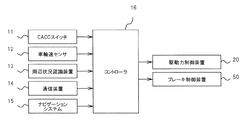
図1は、隊列走行制御装置を示す概略構成図である。
本実施形態における隊列走行制御装置は、CACCスイッチ11と、車輪速センサ12と、周辺状況認識装置13と、通信装置14と、ナビゲーションシステム15と、コントローラ16と、を備える。
In the present embodiment, all the vehicles that travel on the same lane and control the traveling of the host vehicle according to the relative relationship with the preceding vehicle are referred to as a platoon. In this platoon, for example, a vehicle group is formed by about 3 to 5 vehicles, and the inter-vehicle distance between the vehicle groups is made wider than the inter-vehicle distance between the vehicles in the vehicle group. In addition, when a preceding vehicle does not exist in front of the host vehicle, a predetermined set vehicle speed is maintained.
FIG. 1 is a schematic configuration diagram showing a row running control device.
The convoy travel control apparatus according to the present embodiment includes a
CACCスイッチ11は、メインスイッチ、キャンセルスイッチ、リジューム/アクセラレートスイッチ、セット/コーストスイッチ、車間時間設定スイッチ等のスイッチ群からなり、運転者が操作可能となるように、例えばステアリングホイールのスポーク部に設けてある。メインスイッチは、CACCのON/OFFを切り替え、キャンセルスイッチは、CACCの設定を一時的に解除する。リジューム/アクセラレートスイッチは、一時的に解除されたCACCを復帰させる、又は設定車速を例えば5km/h刻みで増加させる。セット/コーストスイッチは、現在の車速を設定車速としてセットする、又は設定車速を例えば5km/h刻みで減少させる。車間時間設定スイッチは、スイッチを押すごとに目標車間時間Ttを例えば長・中・短の三段階に切り替える。これらCACCスイッチ11は、各種操作状況に応じた電圧信号をコントローラ16に出力する。コントローラ16は、入力された電圧信号から各種操作状況を判断する。
The
なお、自車両が車群内で先頭車両を除く後続車両になる場合と、車群内で先頭車両になる場合とで、先行車両に対する目標車間時間を異ならせる必要がある。例えば、後続車両用の目標車間時間を0.7sec程度とすると、先頭車両用の目標車間時間を1.8sec程度にすることが望ましい。そこで、車間時間設定スイッチの操作により、後続車両用の目標車間時間、及び先頭車両用の目標車間時間の双方を個別に設定できる構成としてもよい。また、車間時間設定スイッチの操作により、後続車両用の目標車間時間、及び先頭車両用の目標車間時間の何れか一方を設定すると、予め定めた車間時間だけ加算又は減算することにより、他方が設定される構成としてもよい。 Note that the target inter-vehicle time for the preceding vehicle needs to be different depending on whether the host vehicle is a succeeding vehicle excluding the leading vehicle in the vehicle group or a leading vehicle in the vehicle group. For example, if the target inter-vehicle time for the following vehicle is about 0.7 sec, it is desirable to set the target inter-vehicle time for the leading vehicle to about 1.8 sec. Therefore, it may be configured such that both the target inter-vehicle time for the following vehicle and the target inter-vehicle time for the leading vehicle can be individually set by operating the inter-vehicle time setting switch. In addition, when one of the target inter-vehicle time for the following vehicle and the target inter-vehicle time for the leading vehicle is set by operating the inter-vehicle time setting switch, the other is set by adding or subtracting a predetermined inter-vehicle time. It is good also as a structure to be made.
車輪速センサ12は、各車輪の車輪速度VwFL〜VwRRを検出する。この車輪速センサ12は、例えば車輪と共に回転し円周に突起部(ギヤパルサ)が形成されたセンサロータと、このセンサロータの突起部に対向して設けられたピックアップコイルを有する検出回路と、を備える。そして、センサロータの回転に伴う磁束密度の変化を、ピックアップコイルによって電圧信号に変換してコントローラ16に出力する。コントローラ16は、入力された電圧信号から車輪速度VwFL〜VwRRを判断し、例えば非駆動輪(従動輪)の車輪速平均値や全輪の車輪速平均値を車速として演算する。
The
周辺状況認識装置13は、レーダ装置やステレオカメラからなり、自車両前方の状況を認識する。
レーダ装置は、自車両前方に存在する前方物体までの距離、相対速度、及び方位を検出する。このレーダ装置は、フロントグリル内に設けられたミリ波レーダからなり、検出した各種データをコントローラ16に出力する。距離及び相対速度については、例えばFM‐CW(Frequency Modulation-Continuous Wave)方式を利用し、ドップラ効果による周波数差に応じて距離及び相対速度を検出し、方位については、例えばDBF(Digital Beam Forming)方式を利用し、複数のチャンネルで受信した反射波の位相差に応じて方位を検出する。
The surrounding
The radar apparatus detects a distance to a front object existing in front of the host vehicle, a relative speed, and a direction. This radar apparatus is composed of a millimeter wave radar provided in the front grill, and outputs various detected data to the
ステレオカメラは、車体の前方を撮像する。このステレオカメラは、同一の仕様の2台のカメラからなり、車室内のフロントウィンドウ上部で車幅方向に沿って配置され、且つ光軸及びカメラ座標を平行にしてある。ステレオカメラで撮像した車体前方の画像データは、画像処理装置に入力され、ステレオ画像処理される。すなわち、左カメラ画像と右カメラ画像との視差から画面領域全域にわたって距離分布画像を生成し、この距離分布画像と元画像とに基づいて、前方物体の位置や走行区分線(白線)の検出を行い、検出した各種データをコントローラ16に出力する。
The stereo camera images the front of the vehicle body. This stereo camera is composed of two cameras having the same specifications, is arranged along the vehicle width direction at the upper part of the front window in the vehicle interior, and has an optical axis and camera coordinates in parallel. Image data in front of the vehicle body captured by the stereo camera is input to the image processing apparatus and subjected to stereo image processing. That is, a distance distribution image is generated over the entire screen area from the parallax between the left camera image and the right camera image, and based on this distance distribution image and the original image, the position of the front object and the traveling division line (white line) are detected. The detected various data are output to the
通信装置14は、車群内の車両や車群に加わろうとする他車両との間で、隊列管理のための情報を、車車間通信を介して送受信する。隊列管理のための情報とは、自車両のID番号、自車両の現在位置、先行車両との車間距離、先行車両との相対車速、自車速、加減速度、ブレーキ信号、アクセル信号、ウィンカ信号、各種制御システムの作動信号、異常信号等である。各種制御システムの動作信号には、CACCの作動状態やCC(Cruise Control)の動作状態も含まれる。なお、CCは、予め定めた車速を維持するために、自車両の加減速度を制御するシステムである。
The
車車間通信には、電波通信や光通信を用いる。電波通信では、例えば5.8GHz帯や700MHz帯の周波数帯を用い、直交周波数分割多重方式(OFDM:Orthogonal Frequency Division Multiplex)によって通信を行う。なお、車群内における先頭車両と最後尾車両との間では、直接通信するよりも、中継車両を経由して間接的に通信するマルチホップ通信(アドホック通信)を行うことにより、通信エラーを低減し、通信品質を向上させることができる。光通信では、例えば880nm程度の近赤外線を用い、周波数偏移変調(FSK:Frequency Shift Keying)や振幅偏移変調(ASK:Amplitude Shift Keying)によって通信を行う。 For vehicle-to-vehicle communication, radio wave communication or optical communication is used. In radio communication, for example, a frequency band of 5.8 GHz band or 700 MHz band is used, and communication is performed by an orthogonal frequency division multiplexing (OFDM). Note that communication errors are reduced between the first vehicle and the last vehicle in the vehicle group by performing multi-hop communication (ad hoc communication) that communicates indirectly via a relay vehicle rather than directly communicating. Communication quality can be improved. In optical communication, for example, near infrared light of about 880 nm is used, and communication is performed by frequency shift keying (FSK) or amplitude shift keying (ASK).
ナビゲーションシステム15は、自車両の現在位置と、その現在位置における道路地図情報を認識する。このナビゲーションシステム15は、GPS受信機を有し、四つ以上のGPS衛星から到着する電波の時間差に基づいて自車両の位置(緯度、経度、高度)と進行方向とを認識する。そして、DVD‐ROMドライブやハードディスクドライブに記憶された道路種別、道路線形、車線幅員、車両の通行方向等を含めた道路地図情報を参照し、自車両の現在位置における道路地図情報を認識しコントローラ16に出力する。なお、安全運転支援システム(DSSS:Driving Safety Support Systems)として、双方向無線通信(DSRC:Dedicated Short Range Communication)を利用し、各種データをインフラストラクチャから受信してもよい。
The
コントローラ16は、例えばマイクロコンピュータからなり、各センサからの検出信号に基づいて後述する隊列走行制御処理を実行し、駆動力制御装置20と、ブレーキ制御装置50と、を駆動制御する。
駆動力制御装置20は、回転駆動源の駆動力を制御する。例えば、回転駆動源がエンジンであれば、スロットルバルブの開度、燃料噴射量、点火時期などを調整することで、エンジン出力(回転数やエンジントルク)を制御する。回転駆動源がモータであれば、インバータを介してモータ出力(回転数やモータトルク)を制御する。
The
The driving
次に、ブレーキ制御装置50について説明する。
ブレーキ制御装置50は、各車輪の制動力を制御する。例えば、アンチスキッド制御(ABS)、トラクション制御(TCS)、スタビリティ制御(VDC:Vehicle Dynamics Control)等に用いられるブレーキアクチュエータにより、各車輪に設けられたホイールシリンダの液圧を制御する。
Next, the
The
次に、コントローラ16で所定時間(例えば10msec)毎に実行する隊列走行制御処理について説明する。
ここでは、自車両の属する車群だけが存在するものとし、便宜的にこれを隊列と称して説明する。
図2は、隊列走行制御処理を示すフローチャートである。
先ずステップS101では、各種データを読込む。
続くステップS102では、例えば非駆動輪(従動輪)の車輪速平均値を自車速Vsとして算出する。
Next, the row running control process executed by the
Here, it is assumed that only the vehicle group to which the host vehicle belongs exists, and this will be referred to as a formation for convenience.
FIG. 2 is a flowchart showing the row running control process.
First, in step S101, various data are read.
In the subsequent step S102, for example, the average wheel speed of the non-driven wheels (driven wheels) is calculated as the own vehicle speed Vs.
続くステップS103では、自車両が隊列内の先頭車両であるか、又は後続車両であるか、つまりID番号が#1であるか、又はそれ以外であるかに応じて目標車間時間Ttを設定する。具体的には、自車両が先頭車両であるときには、車間時間設定スイッチによって設定された先頭車両用の目標車間時間TtHを目標車間時間Ttとして設定する。一方、自車両が後続車両であるときには、車間時間設定スイッチによって設定された後続車両用の目標車間時間TtFを目標車間時間Ttとして設定する。
続くステップS104では、目標車間時間Ttを実現するための第一の目標車間距離Dt1を、下記の数式に示すように、目標車間時間Tt、及び先行車両の車速Vaに応じて算出する。先行車両の車速Vaは、先行車両との相対速度Vrと自車速Vsとの差分によって算出する。
Dt1=Va×Tt
In the subsequent step S103, the target inter-vehicle time Tt is set depending on whether the host vehicle is the leading vehicle or the following vehicle in the platoon, that is, whether the ID number is # 1 or other than that. . Specifically, when the host vehicle is the leading vehicle, the target inter-vehicle time Tt H for the leading vehicle set by the inter-vehicle time setting switch is set as the target inter-vehicle time Tt. On the other hand, when the host vehicle is a subsequent vehicle, the target inter-vehicle time Tt F for the subsequent vehicle set by the inter-vehicle time setting switch is set as the target inter-vehicle time Tt.
In the subsequent step S104, the first target inter-vehicle distance Dt1 for realizing the target inter-vehicle time Tt is calculated according to the target inter-vehicle time Tt and the vehicle speed Va of the preceding vehicle, as shown in the following equation. The vehicle speed Va of the preceding vehicle is calculated by the difference between the relative speed Vr with the preceding vehicle and the host vehicle speed Vs.
Dt1 = Va × Tt
続くステップS105では、第一の目標車間距離Dt1を実現するための目標車速Vtを算出する。
先ず、下記の数式に示すように、先行車両の車速Va、第一の目標車間距離Dt1と車間距離Drとの偏差ΔD(=Dt1−Dr)、及び先行車両との相対速度Vrに応じて、基礎目標車速Vb算出する。ここで、K1はVaに乗じるゲインであり、K2はΔDに乗じるゲインであり、K3はVrに乗じるゲインであり、f{ }は、K1×Va、K2×ΔD、及びK3×Vrに応じて基礎目標車速Vbを演算するための関数を表している。
Vb=f{K1×Va、K2×ΔD、K3×Vr}
そして、下記の数式に示すように、予め定めた伝達特性に従い、基準目標車速Vbに一次遅れ系のフィルタ処理を施すことにより、最終的な目標車速Vtを算出する。
In subsequent step S105, a target vehicle speed Vt for realizing the first target inter-vehicle distance Dt1 is calculated.
First, as shown in the following formula, according to the vehicle speed Va of the preceding vehicle, the deviation ΔD (= Dt1−Dr) between the first target inter-vehicle distance Dt1 and the inter-vehicle distance Dr, and the relative speed Vr with respect to the preceding vehicle, The basic target vehicle speed Vb is calculated. Here, K1 is a gain to be multiplied by Va, K2 is a gain to be multiplied by ΔD, K3 is a gain to be multiplied by Vr, and f {} is in accordance with K1 × Va, K2 × ΔD, and K3 × Vr. A function for calculating the basic target vehicle speed Vb is shown.
Vb = f {K1 × Va, K2 × ΔD, K3 × Vr}
Then, as shown in the following mathematical formula, the final target vehicle speed Vt is calculated by subjecting the reference target vehicle speed Vb to a first-order lag filter process according to a predetermined transfer characteristic.

続くステップS106では、目標車速Vtを実現するための目標加減速度Gtを、予め定めた応答特性に従い、下記の数式に示すように、自車速Vs、及び目標車速Vtに応じて算出する。ここで、f{ }は、Vs及びVtに応じて目標加減速度Gtを演算するための関数を表している。なお、自車速Vsが目標車速Vtよりも高いときは、目標加減速度Gtが減速の負値となり、自車速Vsが目標車速Vtよりも低いときは、目標加減速度Gtが加速の正値となる。
Gt=f{Vs、Vt}
In subsequent step S106, a target acceleration / deceleration Gt for realizing the target vehicle speed Vt is calculated according to the own vehicle speed Vs and the target vehicle speed Vt, as shown in the following formula, according to a predetermined response characteristic. Here, f {} represents a function for calculating the target acceleration / deceleration Gt according to Vs and Vt. When the host vehicle speed Vs is higher than the target vehicle speed Vt, the target acceleration / deceleration Gt is a negative deceleration value. When the host vehicle speed Vs is lower than the target vehicle speed Vt, the target acceleration / deceleration Gt is a positive acceleration value. .
Gt = f {Vs, Vt}
続くステップS107では、目標加減速度Gtに対してレートリミッタ処理を行う。すなわち、目標加減速度Gtの単位時間当たりの変化量、ここでは前回値Gt(n−1)からの変化量ΔGtが、予め定めた上限値ΔG1以下であるときには、目標加減速度Gtをそのまま維持する。一方、前回値Gt(n−1)からの変化量ΔGtが、上限値ΔG1よりも大きいときには、前回値Gt(n−1)からの変化量ΔGtが上限値ΔG1となるように、目標加減速度Gtを補正し、その変化率を制限する。 In subsequent step S107, a rate limiter process is performed on the target acceleration / deceleration Gt. That is, when the change amount per unit time of the target acceleration / deceleration Gt, here, the change amount ΔGt from the previous value Gt (n−1) is equal to or less than a predetermined upper limit value ΔG1, the target acceleration / deceleration Gt is maintained as it is. . On the other hand, when the change amount ΔGt from the previous value Gt (n−1) is larger than the upper limit value ΔG1, the target acceleration / deceleration is performed so that the change amount ΔGt from the previous value Gt (n−1) becomes the upper limit value ΔG1. Gt is corrected and the rate of change is limited.
続くステップS108では、下記の数式に示すように、車間時間制御として、目標加減速度Gtを実現するための第一の加減速度指令値Gc1を、目標加減速度Gtに応じて算出する。ここで、Tsは予め定めた設定時間であり、f{ }は、Gtに応じて第一の制御指令値Gc1を演算するための関数を表している。なお、第一の加減速度指令値Gc1は、加速指令となるときに正の値となり、減速指令となるときに負の値となる。
Gc1=f{Gt}×Ts
In subsequent step S108, as shown in the following equation, as the inter-vehicle time control, a first acceleration / deceleration command value Gc1 for realizing the target acceleration / deceleration Gt is calculated according to the target acceleration / deceleration Gt. Here, Ts is a predetermined set time, and f {} represents a function for calculating the first control command value Gc1 according to Gt. The first acceleration / deceleration command value Gc1 is a positive value when it is an acceleration command, and is a negative value when it is a deceleration command.
Gc1 = f {Gt} × Ts
続くステップS109では、先行車両の走行状態を判断する。ここでは、通信装置14を介した先行車両との車車間通信により、先行車両の減速開始を判断する。先行車両が減速を開始するか否かは、例えばブレーキスイッチがOFFからONに切り替わったり、トランスミッションをシフトダウンしたりする等の減速操作から判断する。なお、減速操作とは、運転者による入力だけではなく、障害物との接触回避のために制御介入したり、又は自動運転したりする等、アクセル制御やブレーキ制御を行う際のアクチュエータによる入力をも含む。
In subsequent step S109, the traveling state of the preceding vehicle is determined. Here, the start of deceleration of the preceding vehicle is determined by inter-vehicle communication with the preceding vehicle via the
続くステップS110では、車間距離制御として、先行車両の減速開始を検出した時点の、先行車両との車間距離Drを、第二の目標車間距離Dt2として設定し、且つこの第二の目標車間距離Dt2を維持するための第二の加減速度指令値Gc2を設定する。この第二の加減速度指令値Gc2は、例えば第二の目標車間距離Dt2と車間距離Drとの偏差ΔDに応じた減速度を発生させる設定値であり、減速指令となるので負の値となる。また、予め定めた減速度を発生させる固定値を用いたり、固定値と設定値のセレクトハイ値を用いたりしてもよい。
続くステップS111では、後述する制御切り替え判断処理を実行し、車間時間制御、又は車間距離制御の何れか一方を選択し、最終的な減速度指令値Gcを設定する。
In the following step S110, as the inter-vehicle distance control, the inter-vehicle distance Dr with the preceding vehicle at the time when the start of deceleration of the preceding vehicle is detected is set as the second target inter-vehicle distance Dt2, and the second target inter-vehicle distance Dt2 Is set to a second acceleration / deceleration command value Gc2. The second acceleration / deceleration command value Gc2 is a set value for generating a deceleration according to a deviation ΔD between the second target inter-vehicle distance Dt2 and the inter-vehicle distance Dr, and is a negative value because it is a deceleration command. . Alternatively, a fixed value that generates a predetermined deceleration may be used, or a fixed value and a select high value of a set value may be used.
In the subsequent step S111, a control switching determination process described later is executed, and either one of the inter-vehicle time control or the inter-vehicle distance control is selected, and a final deceleration command value Gc is set.
続くステップS112では、最終的な減速度指令値Gcに実現に応じて、制御指令値としてのエンジントルク指令値及びブレーキ液圧指令値を設定する。減速度指令値Gcが加速指令であるときには、エンジントルク指令値を増加させ、ブレーキ液圧指令値を0にする。また、減速度指令値Gcが減速指令であるときには、エンジントルク指令値を0にして、ブレーキ液圧指令値を増加させる。
続くステップS113では、エンジントルク指令値に応じて駆動力制御装置20を駆動制御すると共に、ブレーキ液圧指令値に応じてブレーキ制御装置50を駆動制御してから所定のメインプログラムに復帰する。
上記が本実施形態の隊列走行制御処理である。
In the subsequent step S112, an engine torque command value and a brake fluid pressure command value as control command values are set according to realization of the final deceleration command value Gc. When the deceleration command value Gc is an acceleration command, the engine torque command value is increased and the brake fluid pressure command value is set to zero. When the deceleration command value Gc is a deceleration command, the engine torque command value is set to 0 and the brake fluid pressure command value is increased.
In the subsequent step S113, the driving
The above is the row running control process of this embodiment.
次に、制御切り替え判断処理について説明する。
図3は、制御切り替え判断処理を示すフローチャートである。
先ずステップS121では、先行車両の走行状態を判断する。ここでは、通信装置14を介した先行車両との車車間通信により、先行車両の減速終了を判断する。先行車両が減速を終了するか否かは、例えばブレーキスイッチがONからOFFに切り替わったり、トランスミッションをシフトアップしたりする等の減速終了操作から判断する。なお、減速終了操作とは、運転者による入力だけではなく、障害物との接触回避のための制御介入を終了したり、又は自動運転したりする等、アクセル制御やブレーキ操作を行う際のアクチュエータによる入力をも含む。
Next, the control switching determination process will be described.
FIG. 3 is a flowchart showing the control switching determination process.
First, in step S121, the traveling state of the preceding vehicle is determined. Here, the end of deceleration of the preceding vehicle is determined by inter-vehicle communication with the preceding vehicle via the
続くステップS122では、先行車両に対する車間時間THW(Time Headway)を算出し、この車間時間THWが予め定めた下限閾値TthMINよりも短いか否かを判定する。
ここで、車間時間THWとは、下記の数式に示すように、先行車両との車間距離Drを自車速Vsで除算した値である。
THW=Dr/Vs
また、下限閾値TthMINとは、下記の数式に示すように、車間時間設定スイッチで設定された目標車間時間Ttから予め定めた余裕代Tmを減算した値である。余裕代Tmは、例えば0.1[sec]程度とする。したがって、目標車間時間Ttが例えば0.7[sec]であるときには、下限閾値TthMINは0.6[sec]程度となる。
TthMIN=Tt−Tm
ここで、判定結果が車間時間THWが下限閾値TthMIN以上であるときには、先行車両への接近傾向はほぼないと判断してステップS123に移行する。一方、判定結果が車間時間THWが下限閾値TthMINよりも短いときには、先行車両への接近傾向にあると判断してステップS125に移行する。
In the following step S122, an inter-vehicle time THW (Time Headway) for the preceding vehicle is calculated, and it is determined whether or not the inter-vehicle time THW is shorter than a predetermined lower threshold Tth MIN .
Here, the inter-vehicle time THW is a value obtained by dividing the inter-vehicle distance Dr with the preceding vehicle by the own vehicle speed Vs, as shown in the following equation.
THW = Dr / Vs
Further, the lower limit threshold value Tth MIN is a value obtained by subtracting a predetermined margin Tm from the target inter-vehicle time Tt set by the inter-vehicle time setting switch, as shown in the following equation. The margin Tm is, for example, about 0.1 [sec]. Therefore, when the target inter-vehicle time Tt is, for example, 0.7 [sec], the lower limit threshold value Tth MIN is about 0.6 [sec].
Tth MIN = Tt-Tm
Here, when the inter-vehicle time THW is equal to or greater than the lower limit threshold value Tth MIN, it is determined that there is almost no tendency to approach the preceding vehicle, and the process proceeds to step S123. On the other hand, when the determination result shows that the inter-vehicle time THW is shorter than the lower limit threshold value Tth MIN , it is determined that the vehicle tends to approach the preceding vehicle, and the process proceeds to step S125.
続くステップS123では、車間距離制御フラグがft=1にセットされているか否かを判定する。車間距離制御フラグは、車間距離制御を車間時間制御に優先して実行するか否かを表すフラグである。すなわち、ft=0のときには、車間距離制御を実行しない、つまり車間時間制御を実行することを表し、ft=1のときには、車間距離制御を車間時間制御に優先して実行することを表す。初期状態では、車間距離制御フラグはft=0にリセットされている。ここで、判定結果がft=0であるときには、車間時間制御を実行中であると判断してステップS124に移行する。一方、判定結果がft=1であるときには、車間距離制御を実行中であると判断してステップS131に移行する。
続くステップS124では、車間時間制御として、第一の加減速度指令値Gc1を最終的な加減速指令値Gcに設定してから所定のメインプログラムに復帰する。
In a succeeding step S123, it is determined whether or not the inter-vehicle distance control flag is set to ft = 1. The inter-vehicle distance control flag is a flag that indicates whether the inter-vehicle distance control is executed with priority over the inter-vehicle time control. That is, when ft = 0, it means that the inter-vehicle distance control is not executed, that is, when the inter-vehicle time control is executed, and when ft = 1, this means that the inter-vehicle distance control is executed with priority over the inter-vehicle time control. In the initial state, the inter-vehicle distance control flag is reset to ft = 0. Here, when the determination result is ft = 0, it is determined that the inter-vehicle time control is being executed, and the process proceeds to step S124. On the other hand, when the determination result is ft = 1, it is determined that the inter-vehicle distance control is being executed, and the process proceeds to step S131.
In the subsequent step S124, as the inter-vehicle time control, the first acceleration / deceleration command value Gc1 is set to the final acceleration / deceleration command value Gc, and then the routine returns to a predetermined main program.
ステップS125では、車間距離制御フラグがft=0にリセットされているか否かを判定する。ここで、判定結果がft=0であるときには、車間時間制御を実行中であると判断してステップS126に移行する。一方、判定結果がft=1であるときには、車間距離制御を実行中であると判断してステップS128に移行する。
ステップS126では、車間時間制御から車間距離制御へと切り替えるために、車間距離制御フラグをft=1にセットする。
続くステップS127では、車間距離制御として、第二の加減速度指令値Gc2を最終的な加減速指令値Gcに設定してから所定のメインプログラムに復帰する。
In step S125, it is determined whether the inter-vehicle distance control flag is reset to ft = 0. Here, when the determination result is ft = 0, it is determined that the inter-vehicle time control is being executed, and the process proceeds to step S126. On the other hand, when the determination result is ft = 1, it is determined that the inter-vehicle distance control is being executed, and the process proceeds to step S128.
In step S126, in order to switch from inter-vehicle time control to inter-vehicle distance control, the inter-vehicle distance control flag is set to ft = 1.
In the following step S127, as the inter-vehicle distance control, the second acceleration / deceleration command value Gc2 is set to the final acceleration / deceleration command value Gc, and then the routine returns to a predetermined main program.
ステップS128では、先行車両が減速を終了したか否かを判定する。ここで、先行車両が減速を終了しているときには、車間距離制御から車間時間制御に復帰させても、先行車両への接近傾向を抑制できると判断してステップS129に移行する。一方、先行車両が減速を終了していないときには、車間距離制御を維持しないと、先行車両への接近傾向を抑制できないと判断してステップS127に移行する。
ステップS129では、車間距離制御から車間時間制御へと切り替える(復帰させる)ために、車間距離制御フラグをft=0にリセットする。
ステップS130では、車間時間制御として、第一の加減速度指令値Gc1を最終的な加減速指令値Gcに設定してから所定のメインプログラムに復帰する。
In step S128, it is determined whether the preceding vehicle has finished decelerating. Here, when the preceding vehicle has finished decelerating, it is determined that the approaching tendency to the preceding vehicle can be suppressed even if the inter-vehicle distance control is returned to the inter-vehicle time control, and the process proceeds to step S129. On the other hand, when the preceding vehicle has not finished decelerating, it is determined that unless the inter-vehicle distance control is maintained, the approach tendency to the preceding vehicle cannot be suppressed, and the process proceeds to step S127.
In step S129, the inter-vehicle distance control flag is reset to ft = 0 in order to switch (return) from inter-vehicle distance control to inter-vehicle time control.
In step S130, as the inter-vehicle time control, the first acceleration / deceleration command value Gc1 is set to the final acceleration / deceleration command value Gc, and then the routine returns to a predetermined main program.
ステップS131では、先行車両が減速を終了したか否かを判定する。ここで、先行車両が減速を終了しているときには、車間距離制御から車間時間制御に復帰させても、先行車両への接近傾向を抑制できると判断してステップS132に移行する。一方、先行車両が減速を終了していないときには、車間距離制御を維持しないと、先行車両への接近傾向を抑制できないと判断してステップS134に移行する。
ステップS132では、車間距離制御から車間時間制御へと切り替える(復帰させる)ために、車間距離制御フラグをft=0にリセットする。
ステップS133では、車間時間制御として、第一の加減速度指令値Gc1を最終的な加減速指令値Gcに設定してから所定のメインプログラムに復帰する。
ステップS134では、車間距離制御として、第二の加減速度指令値Gc2を最終的な加減速指令値Gcに設定してから所定のメインプログラムに復帰する。
上記が本実施形態の制御切り替え判断処理である。
In step S131, it is determined whether the preceding vehicle has finished decelerating. Here, when the preceding vehicle has finished decelerating, it is determined that the approaching tendency to the preceding vehicle can be suppressed even if the inter-vehicle distance control is returned to the inter-vehicle time control, and the process proceeds to step S132. On the other hand, when the preceding vehicle has not finished decelerating, it is determined that the approach tendency to the preceding vehicle cannot be suppressed unless the inter-vehicle distance control is maintained, and the process proceeds to step S134.
In step S132, the inter-vehicle distance control flag is reset to ft = 0 in order to switch (return) the inter-vehicle distance control to the inter-vehicle time control.
In step S133, as the inter-vehicle time control, the first acceleration / deceleration command value Gc1 is set to the final acceleration / deceleration command value Gc, and then the routine returns to a predetermined main program.
In step S134, as the inter-vehicle distance control, the second acceleration / deceleration command value Gc2 is set to the final acceleration / deceleration command value Gc, and then the routine returns to a predetermined main program.
The above is the control switching determination process of this embodiment.
《作用》
次に、第1実施形態の作用について説明する。
先ず、比較例について説明する。
隊列走行として先行車両に追従する場合、車間時間に応じて自車両の加減速度を制御することが考えられる。しかしながら、単に車間時間だけに応じて先行車両に追従すると、例えば先行車両が減速してから自車両が減速するまでの時間差が大きくなるなどして、隊列走行を乱してしまう可能性がある。特に、車間時間を短く設定しているときほど、運転者に違和感を与え、さらに隊列走行の乱れを助長することになる。また、実際の隊列走行では、小型車両や大型車両等が混在することになるので、こうした車両毎に異なる加減速性能の差も、隊列走行の乱れを招く要因となる。
<Action>
Next, the operation of the first embodiment will be described.
First, a comparative example will be described.
When following a preceding vehicle as a platooning, it is conceivable to control the acceleration / deceleration of the host vehicle according to the inter-vehicle time. However, if the preceding vehicle is merely tracked according to the inter-vehicle time, there is a possibility that the platooning may be disturbed, for example, because the time difference from when the preceding vehicle decelerates until the own vehicle decelerates increases. In particular, the shorter the inter-vehicle time is set, the more uncomfortable the driver is, and further the disturbance of platooning is promoted. In actual platooning, small vehicles and large vehicles are mixed, so the difference in acceleration / deceleration performance that differs for each vehicle also causes disturbance in platooning.
図4は、隊列走行における車速の乱れを説明する図である。
図中の(a)は、3台の隊列走行を示しており、図中の(b)は、各車両の車速を示すタイムチャートである。
ここでは、#1が先頭の車両であり、#1の車両に#2の車両が追従し、#2の車両に#3の車両が追従している。そして、#1の車両が減速しても、遅れて#2の車両が減速し、さらに遅れて#3の車両が減速することになり、こうして隊列走行が乱れてゆく。また、#1の車両の減速に対して、#2や#3の車両の減速が遅れることにより、#2や#3の減速量を増加させなければならない。したがって、先頭車両の車速を目標車速としたときに、後続車両になるほど、目標車速に対するオーバーシュート量が大きくなってしまう。
FIG. 4 is a diagram for explaining the disturbance of the vehicle speed in the row running.
(A) in the figure shows three platooning runs, and (b) in the figure is a time chart showing the vehicle speed of each vehicle.
Here, # 1 is the leading vehicle, the # 2 vehicle follows the # 1 vehicle, and the # 3 vehicle follows the # 2 vehicle. Even if the # 1 vehicle decelerates, the # 2 vehicle decelerates with a delay, and the # 3 vehicle decelerates with a delay. Thus, the platooning is disturbed. Further, the deceleration amount of # 2 or # 3 must be increased by delaying the deceleration of
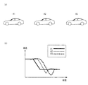
図5は、隊列走行における車間時間の乱れを説明する図である。
図中の(a)は、3台の隊列走行を示しており、図中の(b)は、目標車間距離と各車両間の車間距離とを示すタイムチャートである。
ここでも、#1が先頭の車両であり、#1の車両に#2の車両が追従し、#2の車両に#3の車両が追従している。そして、#1の車両の減速により、目標車間時間を実現するための目標車間距離が減少しても、遅れて#1〜#2間が減少し、さらに遅れて#2〜#3間が減少することになり、こうして隊列走行が乱れてゆく。また、目標車間距離の減少に対して、#1〜#2間や#2〜#3間の車間距離の減少が遅れることで、#2や#3の減速量を増加させなければならない。したがって、後続車両になるほど、目標車間距離に対するオーバーシュート量が大きくなってしまう。
FIG. 5 is a diagram for explaining the disturbance of the inter-vehicle time in the platooning.
(A) in the figure shows three platoons, and (b) in the figure is a time chart showing the target inter-vehicle distance and the inter-vehicle distance.
Again, # 1 is the leading vehicle,
次に、本実施形態について説明する。
本実施形態では、車間時間THWが目標車間時間Ttを維持できているような状況では、車間時間制御を実行し、例えば先行車両が減速し、車間時間THWが目標車間時間Ttに対して下方乖離するような状況では、車間時間制御から車間距離制御へと切り替える。
ここで、車間時間制御と車間距離制御とについて説明する。
車間時間制御とは、目標車間時間Ttを実現するために、自車両の加減速度を制御するモードである。
Next, this embodiment will be described.
In the present embodiment, in a situation where the inter-vehicle time THW can maintain the target inter-vehicle time Tt, inter-vehicle time control is executed, for example, the preceding vehicle decelerates, and the inter-vehicle time THW deviates downward from the target inter-vehicle time Tt. In such a situation, switching from inter-vehicle time control to inter-vehicle distance control is performed.
Here, inter-vehicle time control and inter-vehicle distance control will be described.
The inter-vehicle time control is a mode for controlling the acceleration / deceleration of the host vehicle in order to realize the target inter-vehicle time Tt.
先ず、車群の中で、自車両が先頭車両であるか後続車両であるかに応じて目標車間時間Ttを設定し、自車両が先頭車両であるときには、後続車両であるときよりも長い目標車間時間Ttを設定する(ステップS103)。そして、目標車間時間Ttを実現するための第一の目標車間距離Dt1を算出し(ステップS104)、この第一の目標車間距離Dt1を実現するための目標車速Vtを算出する(ステップS105)。そして、目標車速Vtを実現するための目標加減速度Gtを算出し(ステップS106)、この目標加減速度Gtに対してレートリミッタ処理を行う(ステップS107)。そして、目標加減速度Gtを実現するための第一の加減速度指令値Gc1を算出し(ステップS108)、この第一の加減速度指令値Gc1を最終的な減速度指令値Gcとして設定する(ステップS111)。そして、最終的な減速度指令値Gcに応じて、制御指令値としてのエンジントルク指令値及びブレーキ液圧指令値を設定し(ステップS112)、これらに応じて駆動力制御装置20及びブレーキ制御装置50を駆動制御する(ステップS113)。このような手順で実行されるのが車間時間制御である。
First, in the vehicle group, the target inter-vehicle time Tt is set according to whether the host vehicle is the leading vehicle or the following vehicle. When the own vehicle is the leading vehicle, the target is longer than when the own vehicle is the following vehicle. The inter-vehicle time Tt is set (step S103). Then, a first target inter-vehicle distance Dt1 for realizing the target inter-vehicle time Tt is calculated (step S104), and a target vehicle speed Vt for realizing the first target inter-vehicle distance Dt1 is calculated (step S105). Then, a target acceleration / deceleration Gt for realizing the target vehicle speed Vt is calculated (step S106), and a rate limiter process is performed on the target acceleration / deceleration Gt (step S107). Then, a first acceleration / deceleration command value Gc1 for realizing the target acceleration / deceleration Gt is calculated (step S108), and the first acceleration / deceleration command value Gc1 is set as a final deceleration command value Gc (step S108). S111). Then, an engine torque command value and a brake fluid pressure command value as control command values are set according to the final deceleration command value Gc (step S112), and the driving
一方、車間距離制御とは、第二の目標車間距離Dt2を実現するために、自車両の加減速度を制御するモードである。
先ず、先行車両が減速を開始するか否かを判断する(ステップS109)。そして、先行車両の減速開始を検出した時点の、先行車両との車間距離Drを、第二の目標車間距離Dt2として設定し、且つこの第二の目標車間距離Dt2を維持するための第二の加減速度指令値Gc2を設定する(ステップS110)。この第二の加減速度指令値Gc2は、第二の目標車間距離Dt2と車間距離Drとの偏差ΔDに応じた減速度を発生させる減速指令であり、この第二の加減速度指令値Gc2を最終的な減速度指令値Gcとして設定する(ステップS111)。そして、最終的な減速度指令値Gcに応じて、制御指令値としてのエンジントルク指令値及びブレーキ液圧指令値を設定し(ステップS112)、これらに応じて駆動力制御装置20及びブレーキ制御装置50を駆動制御する(ステップS113)。このような手順で実行されるのが車間距離制御である。
On the other hand, the inter-vehicle distance control is a mode for controlling the acceleration / deceleration of the host vehicle in order to realize the second target inter-vehicle distance Dt2.
First, it is determined whether or not the preceding vehicle starts to decelerate (step S109). Then, the inter-vehicle distance Dr with the preceding vehicle at the time when the deceleration start of the preceding vehicle is detected is set as the second target inter-vehicle distance Dt2, and the second target inter-vehicle distance Dt2 is maintained. An acceleration / deceleration command value Gc2 is set (step S110). The second acceleration / deceleration command value Gc2 is a deceleration command for generating a deceleration according to the deviation ΔD between the second target inter-vehicle distance Dt2 and the inter-vehicle distance Dr. The second acceleration / deceleration command value Gc2 is the final value. Is set as an actual deceleration command value Gc (step S111). Then, an engine torque command value and a brake fluid pressure command value as control command values are set according to the final deceleration command value Gc (step S112), and the driving
車間時間制御では、目標車間時間Ttを実現するために、自車両の加減速度を制御しているので、車間距離Drや自車速Vsのある程度の変動を許容(吸収)しながら、スムーズで安定した追従走行を行うことができる。したがって、先行車両が概ね定速走行しており、車間時間THWが目標車間時間Ttを維持できているような状況では、この車間時間制御が適している。一方、車間距離制御では、先行車両が減速を開始した時点の車間距離Drを、第二の目標車間距離Dt2として設定し、この第二の目標車間距離Dt2を実現するために、自車両の加減速度を制御している。すなわち、先行車両の減速開始を検知すると、車間距離Drの減少に応じて、自車両でも直ちに減速が開始されるので、高応答で先行車両への接近を抑制することができる。したがって、例えば先行車両が減速し、車間時間THWが目標車間時間Ttに対して下方乖離するような状況では、車間距離制御が適している。 In the inter-vehicle time control, the acceleration / deceleration of the host vehicle is controlled in order to realize the target inter-vehicle time Tt, so that smooth and stable while allowing (absorbing) some fluctuations in the inter-vehicle distance Dr and the own vehicle speed Vs. Follow-up driving can be performed. Therefore, this inter-vehicle time control is suitable in a situation where the preceding vehicle is traveling at a substantially constant speed and the inter-vehicle time THW can maintain the target inter-vehicle time Tt. On the other hand, in the inter-vehicle distance control, the inter-vehicle distance Dr at the time when the preceding vehicle starts decelerating is set as the second target inter-vehicle distance Dt2, and in order to realize the second target inter-vehicle distance Dt2, The speed is controlled. That is, when the deceleration start of the preceding vehicle is detected, the host vehicle immediately starts decelerating as the inter-vehicle distance Dr decreases, so that the approach to the preceding vehicle can be suppressed with high response. Therefore, for example, in a situation where the preceding vehicle decelerates and the inter-vehicle time THW deviates downward from the target inter-vehicle time Tt, the inter-vehicle distance control is suitable.
このように、車間時間制御だけで対応するのではなく、必要に応じて車間距離制御を実行することにより、先行車両に追従する車両に、より適切なタイミングで減速させ、良好な隊列走行を維持することができる。
但し、車間時間THWが目標車間時間Ttを下回った時点で、直ちに車間時間制御から車間距離制御へと切り替えると、車両挙動の急変を招く可能性がある。そのため、目標車間時間Ttよりも小さな範囲に予め定めた下限閾値TthMINを設定し、目標車間時間Ttから下限閾値TthMINまでの範囲を、車間時間制御を維持するための不感帯として設定する。
In this way, instead of responding only by inter-vehicle time control, by executing inter-vehicle distance control as necessary, the vehicle following the preceding vehicle can be decelerated at a more appropriate timing, and good platooning can be maintained. can do.
However, when the inter-vehicle time THW falls below the target inter-vehicle time Tt, switching from the inter-vehicle time control to the inter-vehicle distance control immediately may cause a sudden change in the vehicle behavior. For this reason, a predetermined lower limit threshold Tth MIN is set in a range smaller than the target inter-vehicle time Tt, and a range from the target inter-vehicle time Tt to the lower limit threshold Tth MIN is set as a dead zone for maintaining the inter-vehicle time control.
すなわち、車間時間THWが目標車間時間Ttを下回った時点で、直ちに車間時間制御から車間距離制御へと切り替えるのではなく、車間時間制御において、車間距離制御へと切り替えるための車間時間THWに余裕を持たせている。したがって、車間時間THWが下限閾値TthMIN以上であるときには(ステップS122の判定が“No”)、車間時間制御を維持する(ステップS124)。そして、車間時間THWが下限閾値TthMINを下回ったときに(ステップS122の判定が“Yes”)、車間距離制御フラグをft=1にセットし(ステップS126)、車間時間制御から車間距離制御へと切り替える(ステップS127)。 That is, when the inter-vehicle time THW falls below the target inter-vehicle time Tt, the inter-vehicle time control is not immediately switched from the inter-vehicle time control to the inter-vehicle distance control, but in the inter-vehicle time control, there is a margin in the inter-vehicle time THW for switching to the inter-vehicle distance control. I have it. Accordingly, when the inter-vehicle time THW is equal to or greater than the lower limit threshold Tth MIN (determination in Step S122 is “No”), the inter-vehicle time control is maintained (Step S124). When the inter-vehicle time THW falls below the lower limit threshold Tth MIN (“Yes” in step S122), the inter-vehicle distance control flag is set to ft = 1 (step S126), and the inter-vehicle time control is changed to the inter-vehicle distance control. (Step S127).
このように、先ずは車間時間制御を実行しながら、車間距離制御を実行したときのような車両挙動へと近づけてゆき、それから車間距離制御へと移行させている。すなわち、第一の加減速度指令値Gc1が第二の加減速度指令値Gc2に近づくまで待ち、その後、第一の加減速度指令値Gc1から第二の加減速度指令値Gc2へと切り替えて、自車両の加減速度を制御する。これにより、スムーズに制御モードを切り替え、且つ車両挙動の急変を抑制することができる。こうして、先行車両の減速開始を検知した後に、車間時間制御から車間距離制御へと切り替わると、第二の目標車間距離Dt2を実現するための減速度を発生させ、高応答で先行車両への接近を抑制することができる。 As described above, first, while performing the inter-vehicle time control, the vehicle behavior is approached as when the inter-vehicle distance control is performed, and then the shift to the inter-vehicle distance control is performed. That is, it waits until the first acceleration / deceleration command value Gc1 approaches the second acceleration / deceleration command value Gc2, and then switches from the first acceleration / deceleration command value Gc1 to the second acceleration / deceleration command value Gc2, Controls the acceleration / deceleration speed. Thereby, a control mode can be switched smoothly and the sudden change of a vehicle behavior can be suppressed. In this way, when switching from the inter-vehicle time control to the inter-vehicle distance control after detecting the start of deceleration of the preceding vehicle, a deceleration for realizing the second target inter-vehicle distance Dt2 is generated, and the approach to the preceding vehicle with high response is achieved. Can be suppressed.
一方、車間距離制御を実行している状態で、先行車両が減速を解除した場合、この減速解除に対して自車両の減速解除が遅れると、先行車両への追従が遅れ、やはり隊列走行を乱してしまうことになる。そこで、先行車両が減速を終了するか否かを判断する(ステップS121)。そして、先行車両の減速終了を検出したときに(ステップS128、又はS131の判定が“Yes”)、車間距離制御フラグをft=0にリセットし(ステップS129、又はS132)、車間時間制御へと復帰させる(ステップS130、又はS133)。こうして、先行車両が減速を解除した時点で、車間距離制御から車間時間制御に切り替えることで、先行車両との車間距離Drが不必要に拡大することを抑制し、良好な隊列走行を維持することができる。 On the other hand, when the preceding vehicle releases deceleration while the inter-vehicle distance control is being executed, if the own vehicle's deceleration release is delayed with respect to this deceleration release, the follow-up to the preceding vehicle is delayed, which again disturbs platooning. Will end up. Therefore, it is determined whether or not the preceding vehicle ends deceleration (step S121). When the deceleration of the preceding vehicle is detected (determination in step S128 or S131 is “Yes”), the inter-vehicle distance control flag is reset to ft = 0 (step S129 or S132), and the inter-vehicle time control is started. Return (step S130 or S133). In this way, when the preceding vehicle releases the deceleration, switching from the inter-vehicle distance control to the inter-vehicle time control prevents the inter-vehicle distance Dr with the preceding vehicle from being unnecessarily enlarged, and maintains good platooning. Can do.
また、先行車両が減速を開始したか否か、及び先行車両が減速を終了したか否かは、通信装置14を介して先行車両の減速状態を検出することにより判断する。これは、車車間通信を介さずに、先行車両との相対速度Vrに応じて先行車両の減速状態を検出すると、判断に遅れが生じる可能性があるからである。また、減速操作から車両挙動に実際に変化が生じるまでには、ある程度の応答差もある。したがって、先行車両との車車間通信により、ブレーキスイッチのON/OFF信号や、トランスミッションのシフト操作信号を入力すれば、先行車両の挙動が実際に変化する前に、先行車両の減速状態を判断することができる。このように、通信装置14を介した先行車両との車車間通信により、先行車両の減速状態を判断することで、より適切なタイミングで自車両の加減速度を制御でき、良好な隊列走行を維持することができる。
Further, whether or not the preceding vehicle has started decelerating and whether or not the preceding vehicle has finished decelerating are determined by detecting the deceleration state of the preceding vehicle via the
また、車間距離制御を行うための第二の目標車間距離Dt2には、先行車両が減速を開始した時点の車間距離Drを設定する。したがって、第二の目標車間距離Dt2は、先行車両の減速によって車間距離Drが縮まり始める時点の値に相当する。さらには、上記のように、先行車両のブレーキスイッチのON/OFF信号や、トランスミッションのシフト操作信号を入力することで、先行車両の減速によって車間距離Drが縮まるよりも前の時点の値に相当する。したがって、減速開始時点の車間距離Drを車間距離制御の目標値とすることで、先行車両が減速を開始する前の状態を維持しようと自車両の加減速度を制御することになる。これにより、先行車両への接近を可及的に抑制し、良好な隊列走行を維持することができる。 The second target inter-vehicle distance Dt2 for performing inter-vehicle distance control is set to the inter-vehicle distance Dr when the preceding vehicle starts decelerating. Therefore, the second target inter-vehicle distance Dt2 corresponds to a value at the time when the inter-vehicle distance Dr starts to decrease due to the deceleration of the preceding vehicle. Furthermore, as described above, by inputting the ON / OFF signal of the brake switch of the preceding vehicle and the shift operation signal of the transmission, it corresponds to the value at the time before the inter-vehicle distance Dr is reduced by the deceleration of the preceding vehicle. To do. Therefore, by setting the inter-vehicle distance Dr at the start of deceleration as the target value for inter-vehicle distance control, the acceleration / deceleration of the host vehicle is controlled so as to maintain the state before the preceding vehicle starts decelerating. Thereby, the approach to a preceding vehicle can be suppressed as much as possible, and good row running can be maintained.
図6は、第1実施形態の動作を示すタイムチャートである。
ここでは、車間時間THWと、先行車両の減速信号と、車間距離制御フラグの動きについて説明する。
先ず、車間時間THWが目標車間時間Ttを概ね維持しており、車間距離制御フラグがft=0にリセットされていることで、車間時間制御が実行されている。このとき、時点t11で先行車両が減速を開始し、時点t12で先行車両が減速を終了する。この先行車両の一時的な減速により、車間時間THWが僅かに減少するものの、下限閾値thMIN以上の状態を維持しているため、車間距離制御フラグもft=0を維持し、車間時間制御を継続する。
FIG. 6 is a time chart showing the operation of the first embodiment.
Here, the movement of the inter-vehicle time THW, the deceleration signal of the preceding vehicle, and the inter-vehicle distance control flag will be described.
First, the inter-vehicle time control is executed because the inter-vehicle time THW substantially maintains the target inter-vehicle time Tt and the inter-vehicle distance control flag is reset to ft = 0. At this time, the preceding vehicle starts decelerating at time t11, and the preceding vehicle ends decelerating at time t12. Although the inter-vehicle time THW slightly decreases due to the temporary deceleration of the preceding vehicle, the inter-vehicle distance control flag is also maintained at ft = 0 because the inter-vehicle distance control flag is maintained at or above the lower limit threshold th MIN. continue.
その後の時点t13で先行車両が減速を開始すると、車間時間THWが減少しゆき、時点t14で車間時間THWが下限閾値thMINを下回ると、車間距離制御フラグがft=1にセットされるので、車間時間制御から車間距離制御へと切り替わる。この車間距離制御により、先行車両が減速を開始した時点の車間距離Drを維持しようと減速するので、車間時間THWは増加に転じ、直ぐに下限閾値thMINを上回るが、そのまま車間距離制御を維持する。その後の時点t15で先行車両が減速を終了すると、車間距離制御フラグがft=0にリセットされ、車間距離制御から車間時間制御へと復帰する。
このように、車間時間制御だけで対応するのではなく、必要に応じて車間距離制御を実行することにより、先行車両に追従する車両に、より適切なタイミングで減速させ、良好な隊列走行を維持することができる。
When the preceding vehicle starts decelerating thereafter at time t13, the inter-vehicle time THW decreases, and when the inter-vehicle time THW falls below the lower limit threshold th MIN at time t14, the inter-vehicle distance control flag is set to ft = 1. Switch from inter-vehicle time control to inter-vehicle distance control. This inter-vehicle distance control decelerates to maintain the inter-vehicle distance Dr when the preceding vehicle starts decelerating, so the inter-vehicle time THW starts to increase and immediately exceeds the lower limit threshold th MIN , but the inter-vehicle distance control is maintained as it is. . When the preceding vehicle finishes decelerating thereafter at time t15, the inter-vehicle distance control flag is reset to ft = 0, and the inter-vehicle distance control returns to the inter-vehicle time control.
In this way, instead of responding only by inter-vehicle time control, by executing inter-vehicle distance control as necessary, the vehicle following the preceding vehicle can be decelerated at a more appropriate timing, and good platooning can be maintained. can do.
《対応関係》
以上より、車輪速センサ12、ステップS102の処理が「車速検出部」に対応し、周辺状況認識装置13が「車間距離検出部」に対応する。また、CACCスイッチ11、ステップS103の処理が「目標車間時間設定部」に対応し、ステップS104〜S108、S112、S113の処理が「車間時間制御部」に対応する。また、通信装置14、ステップS109、S121の処理が「減速状態検出部」に対応し、ステップS110の処理が「目標車間距離設定部」及び「車間距離制御部」に対応する。また、ステップS111の処理、つまりステップS122〜S134の処理が「制御切り替え部」に対応する。
《Correspondence relationship》
From the above, the
《効果》
次に、第1実施形態における主要部の効果を記す。
(1)本実施形態に係る隊列走行制御装置は、同一車線上の複数の車両と隊列を形成して走行するものにおいて、先行車両に対する目標車間時間Ttを設定し、目標車間時間Ttを実現するために、自車両の加減速度を制御する車間時間制御を実行可能にする。また、先行車両の減速状態を検出し、先行車両との車間距離Drを検出し、先行車両が減速を開始したことを検出した時点の車間距離Drを、第二の目標車間距離Dt2として設定する。そして、第二の目標車間距離Dt2を実現するために、自車両の加減速度を制御する車間距離制御を実行可能にする。また、自車速Vsを検出し、自車速Vs及び先行車両との車間距離Drに応じて、先行車両に対する車間時間THWを検出する。この車間時間THWに応じて、車間時間制御を行うか車間距離制御を行うか何れか一方に切り替える。このとき、車間時間THWが目標車間時間Ttを維持しているときは車間時間制御を行う。また、目標車間時間Ttよりも小さな範囲に予め定めた下限閾値TthMINを設定し、目標車間時間Ttから下限閾値TthMINまでの範囲を、車間時間制御を維持するための不感帯として設定する。そして、車間時間制御を行っている状態で、車間時間THWが下限閾値TthMINを下回ったときに、車間時間制御から車間距離制御に切り替える。
このように、車間時間制御だけで対応するのではなく、必要に応じて車間距離制御を実行することにより、先行車両に追従する車両に、より適切なタイミングで減速させ、良好な隊列走行を維持することができる。さらに、目標車間時間Ttから下限閾値TthMINまでの範囲を、車間時間制御を維持するための不感帯として設定することで、スムーズに制御モードを切り替え、且つ車両挙動の急変を抑制することができる。また、車間時間THWが下限閾値TthMINを下回ったときに、車間時間制御から車間距離制御に切り替えることにより、第二の目標車間距離Dt2を実現するために、速やかに先行車両への接近を抑制することができる。
"effect"
Next, the effect of the main part in 1st Embodiment is described.
(1) The convoy travel control device according to this embodiment forms a convoy with a plurality of vehicles on the same lane, sets a target inter-vehicle time Tt for the preceding vehicle, and realizes the target inter-vehicle time Tt. Therefore, the inter-vehicle time control for controlling the acceleration / deceleration of the host vehicle is made executable. Further, the deceleration state of the preceding vehicle is detected, the inter-vehicle distance Dr with the preceding vehicle is detected, and the inter-vehicle distance Dr at the time when the preceding vehicle has started decelerating is set as the second target inter-vehicle distance Dt2. . And in order to implement | achieve 2nd target inter-vehicle distance Dt2, inter-vehicle distance control which controls the acceleration / deceleration of the own vehicle is enabled. Further, the host vehicle speed Vs is detected, and the inter-vehicle time THW for the preceding vehicle is detected according to the host vehicle speed Vs and the inter-vehicle distance Dr with the preceding vehicle. In accordance with the inter-vehicle time THW, the control is switched to either the inter-vehicle time control or the inter-vehicle distance control. At this time, the inter-vehicle time control is performed when the inter-vehicle time THW maintains the target inter-vehicle time Tt. Further, a predetermined lower threshold Tth MIN is set in a range smaller than the target inter-vehicle time Tt, and a range from the target inter-vehicle time Tt to the lower threshold Tth MIN is set as a dead zone for maintaining the inter-vehicle time control. Then, when the inter-vehicle time control is being performed and the inter-vehicle time THW falls below the lower limit threshold Tth MIN , the inter-vehicle time control is switched to the inter-vehicle distance control.
In this way, instead of responding only by inter-vehicle time control, by executing inter-vehicle distance control as necessary, the vehicle following the preceding vehicle can be decelerated at a more appropriate timing, and good platooning can be maintained. can do. Furthermore, by setting the range from the target inter-vehicle time Tt to the lower limit threshold value Tth MIN as a dead zone for maintaining the inter-vehicle time control, it is possible to smoothly switch the control mode and suppress sudden changes in vehicle behavior. Further, when the inter-vehicle time THW falls below the lower limit threshold value Tth MIN , by switching from the inter-vehicle time control to the inter-vehicle distance control, the approach to the preceding vehicle is quickly suppressed in order to realize the second target inter-vehicle distance Dt2. can do.
(2)本実施形態に係る隊列走行制御装置は、先行車両が減速を終了した時点で、車間距離制御から車間時間制御に切り替える。
このように、先行車両が減速を終了した時点で、車間距離制御から車間時間制御に切り替えることにより、先行車両との車間距離Drが不必要に拡大することを抑制し、良好な隊列走行を維持することができる。
(2) The convoy travel control apparatus according to the present embodiment switches from the inter-vehicle distance control to the inter-vehicle time control when the preceding vehicle finishes decelerating.
In this way, when the preceding vehicle finishes decelerating, switching from inter-vehicle distance control to inter-vehicle time control prevents the inter-vehicle distance Dr from unnecessarily increasing and maintains good platooning can do.
(3)本実施形態に係る隊列走行制御装置は、先行車両との通信により、先行車両の減速状態を検出する。
このように、先行車両との通信により、先行車両の減速状態を検出することにより、より適切なタイミングで自車両の加減速度を制御でき、良好な隊列走行を維持することができる。
(3) The convoy travel control apparatus according to the present embodiment detects the deceleration state of the preceding vehicle through communication with the preceding vehicle.
In this way, by detecting the deceleration state of the preceding vehicle through communication with the preceding vehicle, the acceleration / deceleration of the host vehicle can be controlled at a more appropriate timing, and good platooning can be maintained.
(4)本実施形態に係る隊列走行制御方法は、同一車線上の複数の車両と隊列を形成して走行する際に、先行車両に対する目標車間時間Ttを設定し、この目標車間時間Ttを実現するために、自車両の加減速度を制御する車間時間制御を実行可能にする。また、先行車両の減速状態を検出し、先行車両との車間距離Drを検出し、先行車両が減速を開始したことを検出した時点の車間距離Drを、第二の目標車間距離Dt2として設定する。そして、第二の目標車間距離Dt2を実現するために、自車両の加減速度を制御する車間距離制御を実行可能にする。また、自車速Vsを検出し、自車速Vs及び車間距離Drに応じて、先行車両に対する車間時間THWを検出する。この車間時間THWが目標車間時間Ttを維持しているときは、車間時間制御を行う。また、目標車間時間Ttよりも小さな範囲に予め定めた下限閾値TthMINを設定し、目標車間時間Ttから下限閾値TthMINまでの範囲を、車間時間制御を維持するための不感帯として設定する。そして、車間時間制御を行っている状態で、車間時間THWが下限閾値TthMINを下回ったときに、車間時間制御から車間距離制御に切り替える。 (4) The convoy travel control method according to the present embodiment sets a target inter-vehicle time Tt for the preceding vehicle and realizes this target inter-vehicle time Tt when traveling in a convoy with a plurality of vehicles on the same lane. Therefore, it is possible to execute inter-vehicle time control for controlling the acceleration / deceleration of the host vehicle. Further, the deceleration state of the preceding vehicle is detected, the inter-vehicle distance Dr with the preceding vehicle is detected, and the inter-vehicle distance Dr at the time when the preceding vehicle has started decelerating is set as the second target inter-vehicle distance Dt2. . And in order to implement | achieve 2nd target inter-vehicle distance Dt2, inter-vehicle distance control which controls the acceleration / deceleration of the own vehicle is enabled. Further, the host vehicle speed Vs is detected, and the inter-vehicle time THW for the preceding vehicle is detected according to the host vehicle speed Vs and the inter-vehicle distance Dr. When the inter-vehicle time THW maintains the target inter-vehicle time Tt, inter-vehicle time control is performed. Further, a predetermined lower threshold Tth MIN is set in a range smaller than the target inter-vehicle time Tt, and a range from the target inter-vehicle time Tt to the lower threshold Tth MIN is set as a dead zone for maintaining the inter-vehicle time control. Then, when the inter-vehicle time control is being performed and the inter-vehicle time THW falls below the lower limit threshold Tth MIN , the inter-vehicle time control is switched to the inter-vehicle distance control.
このように、車間時間制御だけで対応するのではなく、必要に応じて車間距離制御を実行することにより、先行車両に追従する車両に、より適切なタイミングで減速させ、良好な隊列走行を維持することができる。さらに、目標車間時間Ttから下限閾値TthMINまでの範囲を、車間時間制御を維持するための不感帯として設定することで、スムーズに制御モードを切り替え、且つ車両挙動の急変を抑制することができる。また、車間時間THWが下限閾値TthMINを下回ったときに、車間時間制御から車間距離制御に切り替えることにより、第二の目標車間距離Dt2を実現するために、速やかに先行車両への接近を抑制することができる。 In this way, instead of responding only by inter-vehicle time control, by executing inter-vehicle distance control as necessary, the vehicle following the preceding vehicle can be decelerated at a more appropriate timing, and good platooning can be maintained. can do. Furthermore, by setting the range from the target inter-vehicle time Tt to the lower limit threshold value Tth MIN as a dead zone for maintaining the inter-vehicle time control, it is possible to smoothly switch the control mode and suppress sudden changes in vehicle behavior. Further, when the inter-vehicle time THW falls below the lower limit threshold value Tth MIN , by switching from the inter-vehicle time control to the inter-vehicle distance control, the approach to the preceding vehicle is quickly suppressed in order to realize the second target inter-vehicle distance Dt2. can do.
《第2実施形態》
《構成》
本実施形態は、車間距離制御を行っている状態で、車間時間THWが目標車間時間Ttを上回ったときには、車間距離制御を維持するものである。また、車間時間THWに対する上限閾値TthMAXを設定し、車間時間THWが上限閾値TthMAXを上回ったときには、上限閾値TthMAXに対応する車間距離DthMAXの維持を実現するために、自車両の加減速度を制御するものである。
装置構成は、前述した第1実施形態と同様である。
<< Second Embodiment >>
"Constitution"
The present embodiment maintains the inter-vehicle distance control when the inter-vehicle time THW exceeds the target inter-vehicle time Tt in the state where the inter-vehicle distance control is performed. Further, an upper limit threshold value Tth MAX for the time headway THW, when the time headway THW is above the upper threshold value Tth MAX, in order to realize the maintenance of the vehicle distance Dth MAX corresponding to the upper limit threshold value Tth MAX, acceleration of the vehicle It controls the speed.
The apparatus configuration is the same as that of the first embodiment described above.
次に、本実施形態の制御切り替え判断処理について説明する。
図7は、第2実施形態の制御切り替え判断処理を示すフローチャートである。
ここでは、前述した第1実施形態において、新たなステップS201、S202の処理を追加してあり、このステップS201の処理は、ステップS123からS131へ移行するときに実行される。なお、ステップS121〜S134の処理については、前述した第1実施形態と同様であるため、共通部分については詳細な説明を省略する。
Next, the control switching determination process of this embodiment will be described.
FIG. 7 is a flowchart illustrating a control switching determination process according to the second embodiment.
Here, in the first embodiment described above, new processes of steps S201 and S202 are added, and the process of step S201 is executed when the process proceeds from step S123 to S131. In addition, about the process of step S121-S134, since it is the same as that of 1st Embodiment mentioned above, detailed description is abbreviate | omitted about a common part.
ステップS201では、車間時間THWが予め定めた上限閾値TthMAXよりも短いか否かを判定する。
ここで、上限閾値TthMAXとは、下記の数式に示すように、車間時間設定スイッチで設定された目標車間時間Ttから予め定めた余裕代Tmを加算した値である。余裕代Tmは、例えば0.1[sec]程度とする。したがって、目標車間時間Ttが例えば0.7[sec]であるときには、上限閾値TthMAXは0.8[sec]程度となる。
TthMAX=Tt+Tm
ここで、判定結果が車間時間THWが上限閾値TthMAXよりも短いときには、先行車両との離間傾向はほぼないと判断してステップS131に移行する。一方、判定結果が車間時間THWが上限閾値TthMAX以上であるときには、先行車両との離間傾向にあると判断してステップS202に移行する。
In step S201, it is determined whether the inter-vehicle time THW is shorter than a predetermined upper limit threshold Tth MAX .
Here, the upper limit threshold value Tth MAX is a value obtained by adding a predetermined margin Tm from the target inter-vehicle time Tt set by the inter-vehicle time setting switch, as shown in the following equation. The margin Tm is, for example, about 0.1 [sec]. Therefore, when the target inter-vehicle time Tt is, for example, 0.7 [sec], the upper limit threshold Tth MAX is about 0.8 [sec].
Tth MAX = Tt + Tm
Here, when the determination result indicates that the inter-vehicle time THW is shorter than the upper limit threshold Tth MAX , it is determined that there is almost no tendency to separate from the preceding vehicle, and the process proceeds to step S131. On the other hand, if the determination result is that the inter-vehicle time THW is equal to or greater than the upper limit threshold Tth MAX, it is determined that the vehicle is in a separation tendency from the preceding vehicle, and the process proceeds to step S202.
ステップS202では、車間距離制御として、上限閾値TthMAX相当の車間距離DthMAXを、第二の目標車間距離Dt2として設定し、且つこの第二の目標車間距離Dt2を維持するための第二の加減速度指令値Gc2を設定する。ここで、上限閾値TthMAX相当の車間距離DthMAXとは、下記の数式に示すように、上限閾値TthMAXに自車速Vsを乗算した値である。
DthMAX=TthMAX×Vs
そして、この第二の加減速度指令値Gc2を最終的な加減速指令値Gcに設定してから所定のメインプログラムに復帰する。
上記が本実施形態の制御切り替え判断処理である。
In step S202, the inter-vehicle distance control, the upper threshold Tth MAX considerable inter-vehicle distance Dth MAX, and set as a second target inter-vehicle distance Dt2, and a second acceleration for maintaining the second target inter-vehicle distance Dt2 A speed command value Gc2 is set. Here, the upper limit threshold value Tth MAX considerable inter-vehicle distance Dth MAX, as shown in the equation below is a value obtained by multiplying the vehicular velocity Vs to the upper threshold Tth MAX.
Dth MAX = Tth MAX x Vs
Then, the second acceleration / deceleration command value Gc2 is set to the final acceleration / deceleration command value Gc, and then the process returns to the predetermined main program.
The above is the control switching determination process of this embodiment.
《作用》
次に、第2実施形態の作用について説明する。
車間距離制御を実行しており、且つ先行車両が減速を終了していない状態で、例えば自車両の減速度が先行車両の減速度よりも相対的に高いと、車間時間THWが徐々に増加してゆく。そして、車間時間THWが目標車間時間Ttを上回ったとしても、先行車両が減速を解除していないので、そのまま車間距離制御を維持する。
但し、車間時間THWが目標車間時間Ttに対して上方乖離し、目標車間時間Ttとの差が大きくなり過ぎると、先行車両が減速を解除した後に、車間時間THWを目標車間時間Ttに復帰させるまでに時間を要してしまう。
<Action>
Next, the operation of the second embodiment will be described.
When the inter-vehicle distance control is executed and the preceding vehicle has not finished decelerating, for example, if the deceleration of the host vehicle is relatively higher than the deceleration of the preceding vehicle, the inter-vehicle time THW gradually increases. Go. Even if the inter-vehicle time THW exceeds the target inter-vehicle time Tt, the preceding vehicle has not released the deceleration, so the inter-vehicle distance control is maintained as it is.
However, if the inter-vehicle time THW deviates upward from the target inter-vehicle time Tt and the difference from the target inter-vehicle time Tt becomes too large, the inter-vehicle time THW is returned to the target inter-vehicle time Tt after the preceding vehicle releases the deceleration. It takes time to complete.
そのため、目標車間時間Ttよりも大きな範囲に予め定めた上限閾値TthMAXを設定し、車間時間THWが上限閾値TthMAX以上であるときには(ステップS201の判定が“No”)、車間距離制御における第二の目標車間距離Dt2を調整する。すなわち、上限閾値TthMAX相当の車間距離DthMAXを、第二の目標車間距離Dt2として設定し直し、この第二の目標車間距離Dt2の維持を実現するために、自車両の加減速度を制御する(ステップS202)。このように、車間距離制御を実行しながら、車間時間THWが大きくなり過ぎることを抑制する。これにより、先行車両が減速を解除した後に、車間時間THWを速やかに目標車間時間Ttへと収束させることができる。 Therefore, when a predetermined upper limit threshold Tth MAX is set in a range larger than the target inter-vehicle time Tt and the inter-vehicle time THW is equal to or greater than the upper threshold Tth MAX (“No” in step S201), the second inter-vehicle distance control is performed. The second target inter-vehicle distance Dt2 is adjusted. That is, the upper threshold Tth MAX considerable inter-vehicle distance Dth MAX, resets the second target inter-vehicle distance Dt2, in order to realize the maintenance of the second target inter-vehicle distance Dt2, to control the acceleration and deceleration of the vehicle (Step S202). In this way, the inter-vehicle time THW is prevented from becoming too large while executing the inter-vehicle distance control. Thereby, after the preceding vehicle releases the deceleration, the inter-vehicle time THW can be quickly converged to the target inter-vehicle time Tt.
図8は、第2実施形態の動作を示すタイムチャートである。
ここでは、車間時間THWと、先行車両の減速信号と、車間距離制御フラグの動きについて説明する。
先ず、車間時間THWが目標車間時間Ttを概ね維持しており、車間距離制御フラグがft=0にリセットされていることで、車間時間制御が実行されている。このとき、時点t21で先行車両が減速を開始し、時点t22で先行車両が減速を終了する。この先行車両の一時的な減速により、車間時間THWが僅かに減少するものの、下限閾値thMIN以上の状態を維持しているため、車間距離制御フラグもft=0を維持し、車間時間制御を継続する。
FIG. 8 is a time chart showing the operation of the second embodiment.
Here, the movement of the inter-vehicle time THW, the deceleration signal of the preceding vehicle, and the inter-vehicle distance control flag will be described.
First, the inter-vehicle time control is executed because the inter-vehicle time THW substantially maintains the target inter-vehicle time Tt and the inter-vehicle distance control flag is reset to ft = 0. At this time, the preceding vehicle starts decelerating at time t21, and the preceding vehicle ends decelerating at time t22. Although the inter-vehicle time THW slightly decreases due to the temporary deceleration of the preceding vehicle, the inter-vehicle distance control flag is also maintained at ft = 0 because the inter-vehicle distance control flag is maintained at or above the lower limit threshold th MIN. continue.
その後の時点t23で先行車両が減速を開始すると、車間時間THWが減少しゆき、時点t24で車間時間THWが下限閾値thMINを下回ると、車間距離制御フラグがft=1にセットされるので、車間時間制御から車間距離制御へと切り替わる。この車間距離制御により、先行車両が減速を開始した時点の車間距離Drを維持しようと減速するので、車間時間THWは増加に転じ、直ぐに下限閾値thMINを上回るが、そのまま車間距離制御を維持する。また、車間時間THWは増加を続け、目標車間時間Ttを上回るが、先行車両が減速を解除していないので、そのまま車間距離制御を維持する。 When the preceding vehicle starts decelerating at time t23 thereafter, the inter-vehicle time THW decreases, and when the inter-vehicle time THW falls below the lower limit threshold th MIN at the time t24, the inter-vehicle distance control flag is set to ft = 1. Switch from inter-vehicle time control to inter-vehicle distance control. This inter-vehicle distance control decelerates to maintain the inter-vehicle distance Dr when the preceding vehicle starts decelerating, so the inter-vehicle time THW starts to increase and immediately exceeds the lower limit threshold th MIN , but the inter-vehicle distance control is maintained as it is. . In addition, the inter-vehicle time THW continues to increase and exceeds the target inter-vehicle time Tt. However, since the preceding vehicle has not released the deceleration, the inter-vehicle distance control is maintained as it is.
但し、車間時間THWが上限閾値thMAXを上回ると、車間距離制御を維持したまま、この上限閾値thMAX相当の車間距離DthMAXを、第二の目標車間距離Dt2として設定する。これにより、車間時間THWの上昇が抑制され、上限閾値thMAXを概ね維持するようになる。その後の時点t25で先行車両が減速を終了すると、車間距離制御フラグがft=0にリセットされ、車間距離制御から車間時間制御へと復帰する。
このように、車間距離制御を維持したまま、第二の目標車間距離Dt2を調整することにより、車間時間THWが大きくなり過ぎることを抑制し、良好な隊列走行を維持することができる。
本実施形態において、その他、前述した第1実施形態と共通する部分については、同様の作用効果が得られるものとし、詳細な説明は省略する。
However, the time headway THW is beyond the upper limit threshold value th MAX, while maintaining the inter-vehicle distance control, the upper limit threshold value th MAX considerable inter-vehicle distance Dth MAX, is set as the second target inter-vehicle distance Dt2. As a result, the increase in the inter-vehicle time THW is suppressed, and the upper limit threshold th MAX is substantially maintained. When the preceding vehicle finishes decelerating thereafter at time t25, the inter-vehicle distance control flag is reset to ft = 0, and the inter-vehicle distance control returns to the inter-vehicle time control.
In this way, by adjusting the second target inter-vehicle distance Dt2 while maintaining the inter-vehicle distance control, it is possible to suppress the inter-vehicle time THW from becoming too large and maintain a good platooning.
In the present embodiment, other parts common to the first embodiment described above are assumed to have the same operational effects, and detailed description thereof is omitted.
《対応関係》
以上、ステップS201の処理が「制御切り替え部」に含まれ、ステップS202の処理が「車間距離制御部」に含まれる。
《効果》
次に、第2実施形態における主要部の効果を記す。
(1)本実施形態の隊列走行制御装置は、車間距離制御を行っている状態で、車間時間THWが目標車間時間Ttを上回ったときには、車間距離制御を維持する。
このように、車間時間THWが目標車間時間Ttを上回ったとしても、少なくとも先行車両が減速を終了するまでは、車間距離制御を維持することにより、先行車両への接近を抑制することができる。
《Correspondence relationship》
As described above, the process of step S201 is included in the “control switching unit”, and the process of step S202 is included in the “inter-vehicle distance control unit”.
"effect"
Next, the effect of the main part in 2nd Embodiment is described.
(1) The convoy travel control device of the present embodiment maintains the inter-vehicle distance control when the inter-vehicle time THW exceeds the target inter-vehicle time Tt in a state where the inter-vehicle distance control is being performed.
Thus, even if the inter-vehicle time THW exceeds the target inter-vehicle time Tt, the approach to the preceding vehicle can be suppressed by maintaining the inter-vehicle distance control at least until the preceding vehicle finishes decelerating.
(2)本実施形態の隊列走行制御装置は、目標車間時間Ttよりも大きな範囲に予め定めた上限閾値TthMAXを設定し、車間時間THWが上限閾値TthMAXを上回ったときは、上限閾値TthMAXに対応する車間距離DthMAXの維持を実現するために、自車両の加減速度を制御する。
このように、車間時間THWが上限閾値TthMAXを上回ったときは、上限閾値TthMAX相当の車間距離DthMAXを維持することにより、車間時間THWが大きくなり過ぎることを抑制し、良好な隊列走行を維持することができる。
(2) The row running control device of the present embodiment sets a predetermined upper limit threshold Tth MAX in a range larger than the target inter-vehicle time Tt, and when the inter-vehicle time THW exceeds the upper limit threshold Tth MAX , the upper limit threshold Tth In order to maintain the inter-vehicle distance Dth MAX corresponding to MAX , the acceleration / deceleration of the host vehicle is controlled.
Thus, when the time headway THW is above the upper threshold value Tth MAX by maintaining the upper threshold Tth MAX considerable inter-vehicle distance Dth MAX, and prevent the time headway THW becomes too large, good row running Can be maintained.
《第3実施形態》
《構成》
本実施形態は、先行車両の車速Vaが、予め定めた閾値Vth以下となったときは、車間距離制御として、予め定めた最小車間距離DrMINの維持を実現するために、自車両の加減速度を制御するものである。
装置構成は、前述した第1実施形態と同様である。
<< Third Embodiment >>
"Constitution"
In the present embodiment, when the vehicle speed Va of the preceding vehicle becomes equal to or less than a predetermined threshold value Vth, the acceleration / deceleration of the host vehicle is realized in order to maintain a predetermined minimum inter-vehicle distance Dr MIN as inter-vehicle distance control. Is to control.
The apparatus configuration is the same as that of the first embodiment described above.
次に、本実施形態の制御切り替え判断処理について説明する。
図9は、第3実施形態の制御切り替え判断処理を示すフローチャートである。
ここでは、前述した第1実施形態において、新たなステップS301、S302の処理を追加してあり、このステップS301の処理は、ステップS121の前に実行される。なお、ステップS121〜S134の処理については、前述した第1実施形態と同様であるため、共通部分については詳細な説明を省略する。
Next, the control switching determination process of this embodiment will be described.
FIG. 9 is a flowchart illustrating a control switching determination process according to the third embodiment.
Here, in the first embodiment described above, new processes of steps S301 and S302 are added, and the process of step S301 is executed before step S121. In addition, about the process of step S121-S134, since it is the same as that of 1st Embodiment mentioned above, detailed description is abbreviate | omitted about a common part.
ステップS301では、先行車両の車速Vaが、予め定めた閾値Vthより大きいか否かを判定する。ここで、閾値Vthとは、例えば40〜50km/h程度の値である。判定結果が、Va>Vthであるときには、適切な車間時間制御を実行できると判断してステップS121に移行する。一方、判定結果がVa≦Vthであるときには、適切な車間時間制御を実行できないと判断してステップS302に移行する。
ステップS302では、車間距離制御として、予め定めた最小車間距離DrMINを、第二の目標車間距離Dt2として設定し、且つこの第二の目標車間距離Dt2を維持するための第二の加減速度指令値Gc2を設定する。ここで、最小車間距離DrMINとは、例えば10m程度の固定値である。そして、この第二の加減速度指令値Gc2を最終的な加減速指令値Gcに設定してから所定のメインプログラムに復帰する。
上記が本実施形態の制御切り替え判断処理である。
In step S301, it is determined whether the vehicle speed Va of the preceding vehicle is greater than a predetermined threshold value Vth. Here, the threshold value Vth is a value of about 40 to 50 km / h, for example. When the determination result is Va> Vth, it is determined that appropriate inter-vehicle time control can be executed, and the process proceeds to step S121. On the other hand, when the determination result is Va ≦ Vth, it is determined that appropriate inter-vehicle time control cannot be executed, and the process proceeds to step S302.
In step S302, as the inter-vehicle distance control, a predetermined minimum inter-vehicle distance Dr MIN is set as the second target inter-vehicle distance Dt2, and a second acceleration / deceleration command for maintaining the second target inter-vehicle distance Dt2 is set. The value Gc2 is set. Here, the minimum inter-vehicle distance Dr MIN is a fixed value of about 10 m, for example. Then, the second acceleration / deceleration command value Gc2 is set to the final acceleration / deceleration command value Gc, and then the process returns to the predetermined main program.
The above is the control switching determination process of this embodiment.
《作用》
次に、第3実施形態の作用について説明する。
車間時間制御では、目標車間時間Ttを実現しようとすると、自車速Vsによって先行車両への車間距離が変化する。すなわち、自車速Vsが高いほど車間距離Drは長くなるが、自車速Vsが低いほど車間距離Drは短くなる。例えば、自車速Vsが50km/h程度のときには車間距離Drが8.3m程度となり、自車速Vsが40km/h程度のときには車間距離Drが6.6m程度となる。しかしながら、いくら自車速Vsが低くても、車間距離Drを短くし過ぎると、運転者に違和感を与える可能性がある。そこで、本実施形態では、自車速Vsが低くなるとしても、最低限の車間距離Drを維持するために、車間時間制御から車間距離制御への切り替えを行う。
<Action>
Next, the operation of the third embodiment will be described.
In the inter-vehicle time control, when the target inter-vehicle time Tt is to be realized, the inter-vehicle distance to the preceding vehicle changes depending on the host vehicle speed Vs. That is, the higher the own vehicle speed Vs, the longer the inter-vehicle distance Dr. However, the lower the own vehicle speed Vs, the shorter the inter-vehicle distance Dr. For example, the inter-vehicle distance Dr is about 8.3 m when the own vehicle speed Vs is about 50 km / h, and the inter-vehicle distance Dr is about 6.6 m when the own vehicle speed Vs is about 40 km / h. However, no matter how low the vehicle speed Vs is, if the inter-vehicle distance Dr is too short, the driver may feel uncomfortable. Therefore, in this embodiment, even if the host vehicle speed Vs decreases, in order to maintain the minimum inter-vehicle distance Dr, switching from inter-vehicle time control to inter-vehicle distance control is performed.
なお、隊列走行の場合、自車速Vsは略先行車両の車速Vaであり、先ず先行車両の車速Vaが変化し、それから自車速Vsが変化することになるため、自車速Vsが低いことを検出するよりも、先行車両の車速Vaが低いことを検出する方が好ましい。
そこで、先行車両の車速Vaが閾値Vth以下であるときには(ステップS301の判定が“No”)、車間距離制御における第二の目標車間距離Dt2を調整する。すなわち、予め定めた最小車間距離DrMINを、第二の目標車間距離Dt2として設定し直し、この第二の目標車間距離Dt2の維持を実現するために、自車両の加減速度を制御する(ステップS302)。このように、車間距離制御に切り替え、車間距離Drが小さくなり過ぎることを抑制する。これにより、先行車両に対して必要以上に接近することを抑制し、運転者に違和感を与えることも抑制できる。
In the case of platooning, the own vehicle speed Vs is substantially the vehicle speed Va of the preceding vehicle. First, the vehicle speed Va of the preceding vehicle changes, and then the own vehicle speed Vs changes, so it is detected that the own vehicle speed Vs is low. It is preferable to detect that the vehicle speed Va of the preceding vehicle is low rather than to do so.
Therefore, when the vehicle speed Va of the preceding vehicle is equal to or lower than the threshold value Vth (the determination in step S301 is “No”), the second target inter-vehicle distance Dt2 in the inter-vehicle distance control is adjusted. That is, the predetermined minimum inter-vehicle distance Dr MIN is reset as the second target inter-vehicle distance Dt2, and the acceleration / deceleration of the host vehicle is controlled in order to realize the maintenance of the second target inter-vehicle distance Dt2 (step) S302). In this way, the inter-vehicle distance control is switched to suppress the inter-vehicle distance Dr from becoming too small. Thereby, it can suppress approaching more than necessary with respect to a preceding vehicle, and it can also suppress giving a driver uncomfortable feeling.
図10は、第3実施形態の動作を示すタイムチャートである。
ここでは、先行車両の車速Vaと、車間距離Drの動きについて説明する。
先ず、先行車両の車速Vaが閾値Vthよりも大きい状態を維持しており、このときは車間時間制御が実行されている。この状態から先行車両が減速し、車速Vaが徐々に減少してゆくと、車間時間制御により、車間距離Drも徐々に短くなる。その後、時点t31で先行車両の車速Vaが閾値Vthを下回ると、車間時間制御から車間距離制御へと切り替わる。この車間距離制御により、車間距離Drの減少が制限され、最小車間距離DrMINを維持する。
FIG. 10 is a time chart showing the operation of the third embodiment.
Here, the movement of the vehicle speed Va of the preceding vehicle and the inter-vehicle distance Dr will be described.
First, the state in which the vehicle speed Va of the preceding vehicle is larger than the threshold value Vth is maintained. At this time, inter-vehicle time control is executed. When the preceding vehicle decelerates from this state and the vehicle speed Va gradually decreases, the inter-vehicle distance Dr also gradually decreases due to the inter-vehicle time control. Thereafter, when the vehicle speed Va of the preceding vehicle falls below the threshold value Vth at time t31, the vehicle time control is switched to the vehicle distance control. By this inter-vehicle distance control, the reduction of the inter-vehicle distance Dr is limited, and the minimum inter-vehicle distance Dr MIN is maintained.
このように、車間時間制御から車間距離制御へと切り替え、第二の目標車間距離Dt2を調整することにより、先行車両に接近し過ぎることを抑制し、良好な隊列走行を維持することができる。
本実施形態において、その他、前述した第1実施形態と共通する部分については、同様の作用効果が得られるものとし、詳細な説明は省略する。
《対応関係》
以上、ステップS301の処理が「制御切り替え部」に含まれ、ステップS302の処理が「車間距離制御部」に含まれる。
In this way, by switching from the inter-vehicle time control to the inter-vehicle distance control and adjusting the second target inter-vehicle distance Dt2, it is possible to prevent the vehicle from approaching the preceding vehicle too much and maintain good platooning.
In the present embodiment, other parts common to the first embodiment described above are assumed to have the same operational effects, and detailed description thereof is omitted.
《Correspondence relationship》
As described above, the process of step S301 is included in the “control switching unit”, and the process of step S302 is included in the “inter-vehicle distance control unit”.
《効果》
次に、第3実施形態における主要部の効果を記す。
(1)本実施形態の隊列走行制御装置は、先行車両の車速Vaが、予め定めた閾値Vth以下となったときは、車間距離制御として、予め定めた最小車間距離DrMINの維持を実現するために、自車両の加減速度を制御する。
このように、先行車両の車速Vaが閾値Vth以下となったときは、車間距離制御によって最小車間距離DrMINの維持することで、先行車両に接近し過ぎることを抑制し、良好な隊列走行を維持することができる。
"effect"
Next, the effect of the main part in 3rd Embodiment is described.
(1) The convoy travel control apparatus of the present embodiment realizes maintenance of a predetermined minimum inter-vehicle distance Dr MIN as inter-vehicle distance control when the vehicle speed Va of the preceding vehicle becomes equal to or less than a predetermined threshold Vth. Therefore, the acceleration / deceleration of the host vehicle is controlled.
As described above, when the vehicle speed Va of the preceding vehicle becomes equal to or lower than the threshold value Vth, by maintaining the minimum inter-vehicle distance Dr MIN by the inter-vehicle distance control, it is possible to suppress the approaching vehicle from being too close and to perform good platooning. Can be maintained.
以上、限られた数の実施形態を参照しながら説明したが、権利範囲はそれらに限定されるものではなく、上記の開示に基づく実施形態の改変は、当業者にとって自明のことである。また、各実施形態は、任意に組み合わせて採用することができる。 Although the present invention has been described with reference to a limited number of embodiments, the scope of rights is not limited thereto, and modifications of the embodiments based on the above disclosure are obvious to those skilled in the art. Moreover, each embodiment can be adopted in any combination.
11 CACCスイッチ
12 車輪速センサ
13 周辺状況認識装置
14 通信装置
15 ナビゲーションシステム
16 コントローラ
20 駆動力制御装置
50 ブレーキ制御装置
11
Claims (7)
先行車両に対する目標車間時間を設定する目標車間時間設定部と、
前記目標車間時間設定部で設定した目標車間時間を実現するために、自車両の加減速度を制御することにより車間時間制御を行う車間時間制御部と、
前記先行車両の減速状態を検出する減速状態検出部と、
前記先行車両との車間距離を検出する車間距離検出部と、
前記減速状態検出部で前記先行車両が減速を開始したことを検出した時点で、前記車間距離検出部で検出した車間距離を、目標車間距離として設定する目標車間距離設定部と、
前記目標車間距離設定部で設定した目標車間距離を実現するために、自車両の加減速度を制御することにより車間距離制御を行う車間距離制御部と、
自車速を検出する車速検出部と、
前記車速検出部で検出した自車速、及び前記車間距離検出部で検出した前記先行車両との車間距離に応じて、前記先行車両に対する車間時間を検出する車間時間検出部と、
前記車間時間検出部で検出した車間時間に応じて、前記車間時間制御部で車間時間制御を行うか前記車間距離制御部で車間距離制御を行うか何れか一方に切り替える制御切り替え部と、を備え、
前記制御切り替え部は、
前記車間時間が前記目標車間時間を維持しているときは、前記車間時間制御部で車間時間制御を行い、前記目標車間時間よりも小さな範囲に予め定めた下限閾値を設定し、前記目標車間時間から前記下限閾値までの範囲を、前記車間時間制御を維持するための不感帯として設定し、前記車間時間制御を行っている状態で、前記車間時間が前記下限閾値を下回ったときには、前記車間時間制御から前記車間距離制御に切り替えることを特徴とする隊列走行制御装置。 In a row running control device that runs in a row with a plurality of vehicles on the same lane,
A target inter-vehicle time setting unit for setting a target inter-vehicle time for the preceding vehicle;
In order to realize the target inter-vehicle time set by the target inter-vehicle time setting unit, an inter-vehicle time control unit that performs inter-vehicle time control by controlling the acceleration / deceleration of the host vehicle,
A deceleration state detector for detecting a deceleration state of the preceding vehicle;
An inter-vehicle distance detection unit for detecting an inter-vehicle distance from the preceding vehicle;
A target inter-vehicle distance setting unit that sets the inter-vehicle distance detected by the inter-vehicle distance detection unit as a target inter-vehicle distance when the deceleration state detection unit detects that the preceding vehicle has started to decelerate;
In order to realize the target inter-vehicle distance set by the target inter-vehicle distance setting unit, an inter-vehicle distance control unit that performs inter-vehicle distance control by controlling the acceleration / deceleration of the host vehicle,
A vehicle speed detector for detecting the vehicle speed;
An inter-vehicle time detection unit that detects an inter-vehicle time with respect to the preceding vehicle according to an own vehicle speed detected by the vehicle speed detection unit and an inter-vehicle distance with the preceding vehicle detected by the inter-vehicle distance detection unit;
A control switching unit that switches between either the inter-vehicle time control by the inter-vehicle time control unit or the inter-vehicle distance control by the inter-vehicle distance control unit according to the inter-vehicle time detected by the inter-vehicle time detection unit. ,
The control switching unit
When the inter-vehicle time maintains the target inter-vehicle time, the inter-vehicle time control unit performs inter-vehicle time control, sets a predetermined lower limit threshold in a range smaller than the target inter-vehicle time, and the target inter-vehicle time Is set as a dead zone for maintaining the inter-vehicle time control, and the inter-vehicle time control is performed when the inter-vehicle time falls below the lower-limit threshold in the state where the inter-vehicle time control is performed. A convoy travel control device characterized in that the control is switched to the inter-vehicle distance control.
前記減速状態検出部は、前記先行車両が減速を終了した時点で、前記車間距離制御から前記車間時間制御に切り替えることを特徴とする請求項1に記載の隊列走行制御装置。 The control switching unit
The platooning travel control device according to claim 1, wherein the deceleration state detection unit switches from the inter-vehicle distance control to the inter-vehicle time control when the preceding vehicle finishes decelerating.
前記先行車両との通信により、前記先行車両の減速状態を検出することを特徴とする請求項1又は2に記載の隊列走行制御装置。 The deceleration state detector is
The row running control device according to claim 1, wherein a deceleration state of the preceding vehicle is detected by communication with the preceding vehicle.
前記車間距離制御を行っている状態で、前記車間時間が前記目標車間時間を上回ったときには、前記車間距離制御を維持することを特徴とする請求項1〜3の何れか一項に記載の隊列走行制御装置。 The control switching unit
The platoon according to any one of claims 1 to 3, wherein the inter-vehicle distance control is maintained when the inter-vehicle time exceeds the target inter-vehicle time while the inter-vehicle distance control is being performed. Travel control device.
前記目標車間時間よりも大きな範囲に予め定めた上限閾値を設定し、前記車間時間が前記上限閾値を上回ったときには、前記上限閾値に対応する車間距離の維持を実現するために、自車両の加減速度を制御することを特徴とする請求項4に記載の隊列走行制御装置。 The inter-vehicle distance control unit
A predetermined upper limit threshold is set in a range larger than the target inter-vehicle time, and when the inter-vehicle time exceeds the upper threshold, the vehicle is adjusted in order to maintain the inter-vehicle distance corresponding to the upper threshold The row running control device according to claim 4, wherein the row running control device controls the speed.
前記先行車両の車速が、予め定めた閾値以下となったときは、前記車間距離制御部で車間距離制御を行い、
前記車間距離制御部は、
予め定めた最小車間距離の維持を実現するために、自車両の加減速度を制御することを特徴とする請求項1〜5の何れか一項に記載の隊列走行制御装置。 The control switching unit
When the vehicle speed of the preceding vehicle is equal to or less than a predetermined threshold, the inter-vehicle distance control unit performs inter-vehicle distance control,
The inter-vehicle distance control unit
The platooning control device according to any one of claims 1 to 5, wherein an acceleration / deceleration of the host vehicle is controlled in order to maintain a predetermined minimum inter-vehicle distance.
先行車両に対する目標車間時間を設定し、前記目標車間時間を実現するために、自車両の加減速度を制御する車間時間制御を実行可能とし、
前記先行車両の減速状態を検出し、前記先行車両との車間距離を検出し、前記先行車両が減速を開始したことを検出した時点の前記車間距離を、目標車間距離として設定し、前記目標車間距離を実現するために、自車両の加減速度を制御する車間距離制御を実行可能とし、
自車速を検出し、前記自車速、及び前記車間距離に応じて、前記先行車両に対する車間時間を検出し、前記車間時間が前記目標車間時間を維持しているときは、前記車間時間制御を行い、前記目標車間時間よりも小さな範囲に予め定めた下限閾値を設定し、前記目標車間時間から前記下限閾値までの範囲を、前記車間時間制御を維持するための不感帯として設定し、前記車間時間制御を行っている状態で、前記車間時間が前記下限閾値を下回ったときには、前記車間時間制御から前記車間距離制御に切り替えることを特徴とする隊列走行制御方法。 When traveling in a formation with multiple vehicles on the same lane,
In order to set the target inter-vehicle time for the preceding vehicle and realize the target inter-vehicle time, it is possible to execute inter-vehicle time control for controlling the acceleration / deceleration of the host vehicle,
Detecting a deceleration state of the preceding vehicle, detecting an inter-vehicle distance from the preceding vehicle, setting the inter-vehicle distance at the time when the preceding vehicle has started decelerating as a target inter-vehicle distance, In order to realize the distance, it is possible to execute inter-vehicle distance control that controls acceleration / deceleration of the host vehicle,
The own vehicle speed is detected, the following time is detected for the preceding vehicle according to the own vehicle speed and the inter-vehicle distance, and the inter-vehicle time control is performed when the inter-vehicle time maintains the target inter-vehicle time. A predetermined lower threshold is set in a range smaller than the target inter-vehicle time, a range from the target inter-vehicle time to the lower threshold is set as a dead zone for maintaining the inter-vehicle time control, and the inter-vehicle time control When the inter-vehicle time falls below the lower limit threshold while the vehicle is being operated, the convoy travel control method switches from the inter-vehicle time control to the inter-vehicle distance control.
Priority Applications (1)
| Application Number | Priority Date | Filing Date | Title |
|---|---|---|---|
| JP2013148682A JP6119476B2 (en) | 2013-07-17 | 2013-07-17 | Convoy travel control device and convoy travel control method |
Applications Claiming Priority (1)
| Application Number | Priority Date | Filing Date | Title |
|---|---|---|---|
| JP2013148682A JP6119476B2 (en) | 2013-07-17 | 2013-07-17 | Convoy travel control device and convoy travel control method |
Publications (2)
| Publication Number | Publication Date |
|---|---|
| JP2015022422A JP2015022422A (en) | 2015-02-02 |
| JP6119476B2 true JP6119476B2 (en) | 2017-04-26 |
Family
ID=52486837
Family Applications (1)
| Application Number | Title | Priority Date | Filing Date |
|---|---|---|---|
| JP2013148682A Active JP6119476B2 (en) | 2013-07-17 | 2013-07-17 | Convoy travel control device and convoy travel control method |
Country Status (1)
| Country | Link |
|---|---|
| JP (1) | JP6119476B2 (en) |
Families Citing this family (10)
| Publication number | Priority date | Publication date | Assignee | Title |
|---|---|---|---|---|
| JP6478027B2 (en) * | 2015-02-13 | 2019-03-06 | アイシン・エィ・ダブリュ株式会社 | Convoy travel management device and convoy travel management program |
| JP2017081432A (en) * | 2015-10-28 | 2017-05-18 | 本田技研工業株式会社 | Vehicle control apparatus, vehicle control method, and vehicle control program |
| KR101846631B1 (en) | 2015-12-08 | 2018-04-06 | 현대자동차주식회사 | Method for joining driving the ranks of vehicle |
| KR102429478B1 (en) * | 2016-04-15 | 2022-08-05 | 현대자동차주식회사 | Apparatus for controlling group driving and method thereof |
| US10482767B2 (en) | 2016-12-30 | 2019-11-19 | Bendix Commercial Vehicle Systems Llc | Detection of extra-platoon vehicle intermediate or adjacent to platoon member vehicles |
| KR102383436B1 (en) * | 2017-12-01 | 2022-04-07 | 현대자동차주식회사 | Platooning control apparatus and method |
| JP7064354B2 (en) * | 2018-03-07 | 2022-05-10 | ワブコジャパン株式会社 | Procession method and vehicle |
| JPWO2020084915A1 (en) * | 2018-10-24 | 2021-09-02 | 日立Astemo株式会社 | How to brake the vehicle |
| EP3751536B1 (en) * | 2019-06-12 | 2024-03-27 | Volkswagen AG | Method for determining a high-density platooning driving maneuver, apparatus, vehicle and computer program |
| CN113212449B (en) * | 2021-04-30 | 2022-06-07 | 重庆长安汽车股份有限公司 | Function trigger parameter adjusting method of front collision early warning system |
Family Cites Families (4)
| Publication number | Priority date | Publication date | Assignee | Title |
|---|---|---|---|---|
| JP2007132768A (en) * | 2005-11-10 | 2007-05-31 | Hitachi Ltd | Vehicle-mounted radar system having communications function |
| JP5516070B2 (en) * | 2010-05-25 | 2014-06-11 | トヨタ自動車株式会社 | Vehicle group management method and platooning communication system |
| JP5573461B2 (en) * | 2010-07-27 | 2014-08-20 | トヨタ自動車株式会社 | Vehicle control system |
| JP2012240532A (en) * | 2011-05-18 | 2012-12-10 | Nissan Motor Co Ltd | Travel control device for vehicle |
-
2013
- 2013-07-17 JP JP2013148682A patent/JP6119476B2/en active Active
Also Published As
| Publication number | Publication date |
|---|---|
| JP2015022422A (en) | 2015-02-02 |
Similar Documents
| Publication | Publication Date | Title |
|---|---|---|
| JP6119476B2 (en) | Convoy travel control device and convoy travel control method | |
| JP6252007B2 (en) | Convoy travel control device, convoy travel control method, travel control device | |
| JP6183023B2 (en) | Convoy travel control device and convoy travel control method | |
| JP6183022B2 (en) | Convoy travel control device and convoy travel control method | |
| CN109720345B (en) | Cut-in vehicle monitoring method and system | |
| US9511769B2 (en) | Speed control method and system | |
| US20210163000A1 (en) | Method and system for distance control of a subject vehicle | |
| US10829128B2 (en) | Driving support device | |
| JP6350465B2 (en) | Vehicle control device | |
| US11505210B2 (en) | Method and device for the automatic control of the longitudinal dynamics of a vehicle | |
| JP7190345B2 (en) | Vehicle motion control device and method | |
| JP2009018727A (en) | Vehicular driving support apparatus | |
| JP5118468B2 (en) | Vehicle travel control device. | |
| WO2022224587A1 (en) | Vehicle control device | |
| WO2019244676A1 (en) | Traveling control device and traveling control method | |
| US20220185290A1 (en) | A method for a lane change of a plurality of vehicles | |
| JP2019202662A (en) | Vehicle control device | |
| JP2021008153A (en) | Vehicle travelling control device | |
| US20240083430A1 (en) | Adaptive cruise control system and method | |
| US20230294680A1 (en) | Driving assistance device, driving assistance method, and storage medium | |
| US20240174230A1 (en) | Vehicle control device | |
| JP2007050755A (en) | Vehicle travelling controller | |
| JP2022178065A (en) | Vehicle driving assistance system | |
| JP2023117727A (en) | Vehicle control device | |
| JP2019189031A (en) | Travel-in-column system |
Legal Events
| Date | Code | Title | Description |
|---|---|---|---|
| A621 | Written request for application examination |
Free format text: JAPANESE INTERMEDIATE CODE: A621 Effective date: 20160325 |
|
| A977 | Report on retrieval |
Free format text: JAPANESE INTERMEDIATE CODE: A971007 Effective date: 20170131 |
|
| TRDD | Decision of grant or rejection written | ||
| A01 | Written decision to grant a patent or to grant a registration (utility model) |
Free format text: JAPANESE INTERMEDIATE CODE: A01 Effective date: 20170228 |
|
| A61 | First payment of annual fees (during grant procedure) |
Free format text: JAPANESE INTERMEDIATE CODE: A61 Effective date: 20170313 |
|
| R151 | Written notification of patent or utility model registration |
Ref document number: 6119476 Country of ref document: JP Free format text: JAPANESE INTERMEDIATE CODE: R151 |