JP6112938B2 - Information processing apparatus, control method therefor, and program - Google Patents
Information processing apparatus, control method therefor, and program Download PDFInfo
- Publication number
- JP6112938B2 JP6112938B2 JP2013073048A JP2013073048A JP6112938B2 JP 6112938 B2 JP6112938 B2 JP 6112938B2 JP 2013073048 A JP2013073048 A JP 2013073048A JP 2013073048 A JP2013073048 A JP 2013073048A JP 6112938 B2 JP6112938 B2 JP 6112938B2
- Authority
- JP
- Japan
- Prior art keywords
- information processing
- processing apparatus
- power saving
- packet
- pattern
- Prior art date
- Legal status (The legal status is an assumption and is not a legal conclusion. Google has not performed a legal analysis and makes no representation as to the accuracy of the status listed.)
- Expired - Fee Related
Links
Images


Classifications
-
- G—PHYSICS
- G06—COMPUTING; CALCULATING OR COUNTING
- G06F—ELECTRIC DIGITAL DATA PROCESSING
- G06F1/00—Details not covered by groups G06F3/00 - G06F13/00 and G06F21/00
- G06F1/26—Power supply means, e.g. regulation thereof
- G06F1/32—Means for saving power
- G06F1/3203—Power management, i.e. event-based initiation of a power-saving mode
- G06F1/3234—Power saving characterised by the action undertaken
- G06F1/3243—Power saving in microcontroller unit
-
- G—PHYSICS
- G06—COMPUTING; CALCULATING OR COUNTING
- G06F—ELECTRIC DIGITAL DATA PROCESSING
- G06F1/00—Details not covered by groups G06F3/00 - G06F13/00 and G06F21/00
- G06F1/26—Power supply means, e.g. regulation thereof
- G06F1/32—Means for saving power
- G06F1/3203—Power management, i.e. event-based initiation of a power-saving mode
- G06F1/3206—Monitoring of events, devices or parameters that trigger a change in power modality
- G06F1/3209—Monitoring remote activity, e.g. over telephone lines or network connections
-
- G—PHYSICS
- G06—COMPUTING; CALCULATING OR COUNTING
- G06F—ELECTRIC DIGITAL DATA PROCESSING
- G06F1/00—Details not covered by groups G06F3/00 - G06F13/00 and G06F21/00
- G06F1/26—Power supply means, e.g. regulation thereof
- G06F1/32—Means for saving power
- G06F1/3203—Power management, i.e. event-based initiation of a power-saving mode
- G06F1/3234—Power saving characterised by the action undertaken
- G06F1/325—Power saving in peripheral device
- G06F1/3284—Power saving in printer
-
- H—ELECTRICITY
- H04—ELECTRIC COMMUNICATION TECHNIQUE
- H04N—PICTORIAL COMMUNICATION, e.g. TELEVISION
- H04N1/00—Scanning, transmission or reproduction of documents or the like, e.g. facsimile transmission; Details thereof
- H04N1/00127—Connection or combination of a still picture apparatus with another apparatus, e.g. for storage, processing or transmission of still picture signals or of information associated with a still picture
- H04N1/00204—Connection or combination of a still picture apparatus with another apparatus, e.g. for storage, processing or transmission of still picture signals or of information associated with a still picture with a digital computer or a digital computer system, e.g. an internet server
- H04N1/00209—Transmitting or receiving image data, e.g. facsimile data, via a computer, e.g. using e-mail, a computer network, the internet, I-fax
- H04N1/00214—Transmitting or receiving image data, e.g. facsimile data, via a computer, e.g. using e-mail, a computer network, the internet, I-fax details of transmission
- H04N1/00217—Transmitting or receiving image data, e.g. facsimile data, via a computer, e.g. using e-mail, a computer network, the internet, I-fax details of transmission only involving computer data transmission protocols, e.g. SMTP, WAP or HTTP
-
- H—ELECTRICITY
- H04—ELECTRIC COMMUNICATION TECHNIQUE
- H04N—PICTORIAL COMMUNICATION, e.g. TELEVISION
- H04N1/00—Scanning, transmission or reproduction of documents or the like, e.g. facsimile transmission; Details thereof
- H04N1/00885—Power supply means, e.g. arrangements for the control of power supply to the apparatus or components thereof
- H04N1/00888—Control thereof
- H04N1/00891—Switching on or off, e.g. for saving power when not in use
-
- H—ELECTRICITY
- H04—ELECTRIC COMMUNICATION TECHNIQUE
- H04N—PICTORIAL COMMUNICATION, e.g. TELEVISION
- H04N1/00—Scanning, transmission or reproduction of documents or the like, e.g. facsimile transmission; Details thereof
- H04N1/00885—Power supply means, e.g. arrangements for the control of power supply to the apparatus or components thereof
- H04N1/00888—Control thereof
- H04N1/00896—Control thereof using a low-power mode, e.g. standby
-
- H—ELECTRICITY
- H04—ELECTRIC COMMUNICATION TECHNIQUE
- H04N—PICTORIAL COMMUNICATION, e.g. TELEVISION
- H04N1/00—Scanning, transmission or reproduction of documents or the like, e.g. facsimile transmission; Details thereof
- H04N1/32—Circuits or arrangements for control or supervision between transmitter and receiver or between image input and image output device, e.g. between a still-image camera and its memory or between a still-image camera and a printer device
- H04N1/333—Mode signalling or mode changing; Handshaking therefor
- H04N1/33376—Mode signalling or mode changing; Handshaking therefor according to characteristics or state of one of the communicating parties, e.g. available memory capacity
- H04N1/33384—Mode signalling or mode changing; Handshaking therefor according to characteristics or state of one of the communicating parties, e.g. available memory capacity according to transient characteristics or state
-
- H—ELECTRICITY
- H04—ELECTRIC COMMUNICATION TECHNIQUE
- H04N—PICTORIAL COMMUNICATION, e.g. TELEVISION
- H04N2201/00—Indexing scheme relating to scanning, transmission or reproduction of documents or the like, and to details thereof
- H04N2201/0008—Connection or combination of a still picture apparatus with another apparatus
- H04N2201/0034—Details of the connection, e.g. connector, interface
- H04N2201/0048—Type of connection
- H04N2201/0055—By radio
-
- Y—GENERAL TAGGING OF NEW TECHNOLOGICAL DEVELOPMENTS; GENERAL TAGGING OF CROSS-SECTIONAL TECHNOLOGIES SPANNING OVER SEVERAL SECTIONS OF THE IPC; TECHNICAL SUBJECTS COVERED BY FORMER USPC CROSS-REFERENCE ART COLLECTIONS [XRACs] AND DIGESTS
- Y02—TECHNOLOGIES OR APPLICATIONS FOR MITIGATION OR ADAPTATION AGAINST CLIMATE CHANGE
- Y02D—CLIMATE CHANGE MITIGATION TECHNOLOGIES IN INFORMATION AND COMMUNICATION TECHNOLOGIES [ICT], I.E. INFORMATION AND COMMUNICATION TECHNOLOGIES AIMING AT THE REDUCTION OF THEIR OWN ENERGY USE
- Y02D10/00—Energy efficient computing, e.g. low power processors, power management or thermal management
-
- Y—GENERAL TAGGING OF NEW TECHNOLOGICAL DEVELOPMENTS; GENERAL TAGGING OF CROSS-SECTIONAL TECHNOLOGIES SPANNING OVER SEVERAL SECTIONS OF THE IPC; TECHNICAL SUBJECTS COVERED BY FORMER USPC CROSS-REFERENCE ART COLLECTIONS [XRACs] AND DIGESTS
- Y02—TECHNOLOGIES OR APPLICATIONS FOR MITIGATION OR ADAPTATION AGAINST CLIMATE CHANGE
- Y02D—CLIMATE CHANGE MITIGATION TECHNOLOGIES IN INFORMATION AND COMMUNICATION TECHNOLOGIES [ICT], I.E. INFORMATION AND COMMUNICATION TECHNOLOGIES AIMING AT THE REDUCTION OF THEIR OWN ENERGY USE
- Y02D30/00—Reducing energy consumption in communication networks
- Y02D30/70—Reducing energy consumption in communication networks in wireless communication networks
Landscapes
- Engineering & Computer Science (AREA)
- Theoretical Computer Science (AREA)
- General Engineering & Computer Science (AREA)
- Multimedia (AREA)
- Signal Processing (AREA)
- General Physics & Mathematics (AREA)
- Physics & Mathematics (AREA)
- Computer Networks & Wireless Communication (AREA)
- Computing Systems (AREA)
- Facsimiles In General (AREA)
- Power Sources (AREA)
- Small-Scale Networks (AREA)
- Mobile Radio Communication Systems (AREA)
- Accessory Devices And Overall Control Thereof (AREA)
Description
本発明は、情報処理装置及びその制御方法、並びにプログラムに関し、特に、省電力状態でネットワークに無線接続可能な情報処理装置の通信要求に対する応答制御技術に関する。 The present invention relates to an information processing apparatus, a control method thereof, and a program, and more particularly, to a response control technique for a communication request of an information processing apparatus that can be wirelessly connected to a network in a power saving state.
近年、無線LAN(Local Area Network)等のネットワーク環境の普及に伴い、ネットワーク上に設置された無線LANアクセスポイントを介して無線接続可能な無線LAN機能を備えた機器が普及している。例えば、無線LANが構築されたオフィスでは、無線LAN機能が搭載された複合機(マルチファンクションプリンタ)と複数のPC(Personal Computer)との間で無線通信によるデータのやり取りが行われている。 In recent years, with the spread of a network environment such as a wireless LAN (Local Area Network), a device having a wireless LAN function that can be wirelessly connected via a wireless LAN access point installed on the network has become widespread. For example, in an office where a wireless LAN is constructed, data is exchanged by wireless communication between a multifunction device (multifunction printer) equipped with a wireless LAN function and a plurality of PCs (Personal Computers).
また、環境に対する関心の高まりから、オフィス等で使用されるあらゆる電気機器の消費電力を削減する省電力化技術への対応が強く求められている。無線LAN対応機器の省電力化技術として、IEEE(Institute of Electrical and Electronic Enginerrs)が標準化するIEEE802.11v規格がある。このIEEE802.11vを構成する機能に、ARP(Adress Resolution Protocol)プロキシがある。このARPプロキシでは、無線LANアクセスポイントが、配下とする無線LANクライアント機器の代理でARP要求に応答する。これにより、無線LANクライアント機器は、ネットワーク上でブロードキャストされ高頻度で受信するARP要求応答のためだけに動作することを回避して省電力状態を継続することが可能となる。 In addition, due to the growing interest in the environment, there is a strong demand for a power-saving technology that reduces the power consumption of all electrical devices used in offices and the like. As a power saving technology for wireless LAN compatible devices, there is an IEEE 802.11v standard standardized by IEEE (Institut of Electrical and Electronic Engineers). As a function constituting the IEEE802.11v, there is an ARP (Address Resolution Protocol) proxy. In this ARP proxy, a wireless LAN access point responds to an ARP request on behalf of a wireless LAN client device under its control. As a result, the wireless LAN client device can avoid the operation only for the ARP request response that is broadcast on the network and received at a high frequency, and can continue the power saving state.
一方、複合機の省電力化技術として、通常状態で一定時間機器の操作が行われない場合に自律動作により省電力状態に移行して待機時電力を削減する技術が知られている。 On the other hand, as a power saving technique for a multifunction machine, a technique is known that reduces standby power by shifting to a power saving state by autonomous operation when a device is not operated for a certain period of time in a normal state.
また、省電力状態で主制御部よりも小規模でかつ最小限の供給電力で動作する副制御部を備え、通常状態では主制御部が行うネットワーク処理を、省電力状態では副制御部が主制御部の代理で行うことでネットワーク接続性と省電力化とを両立させる技術がある。 It also has a sub-control unit that is smaller than the main control unit and operates with the minimum supply power in the power-saving state, and performs network processing performed by the main control unit in the normal state, and the sub-control unit in the power-saving state. There is a technology that achieves both network connectivity and power saving by acting on behalf of the control unit.
省電力状態で副制御部が行うネットワーク処理は、主制御部が行うネットワーク処理と比較して少規模であり、PCから複合機宛ての全ての通信要求に対して応答処理することは困難である。副制御部は、受信した通信要求が処理可能か否かを判別し、処理不可能な場合、複合機を省電力状態から通常状態に速やかに移行させて主制御部がネットワーク応答する必要がある。これを実現するために、情報処理装置が省電力状態で受信する通信要求について、省電力状態で応答できるか、または、通常状態に移行して応答する必要があるかを判別する技術が開示されている。例えば、特許文献1では、情報処理装置が省電力状態で受信する通信要求をパターン判別する技術が提案されている。
The network processing performed by the sub-control unit in the power saving state is smaller than the network processing performed by the main control unit, and it is difficult to respond to all communication requests addressed to the multifunction peripheral from the PC. . The sub-control unit determines whether or not the received communication request can be processed. If the request cannot be processed, the main control unit needs to make a network response from the power saving state to the normal state quickly . In order to realize this, a technology for determining whether a communication request received by the information processing apparatus in the power saving state can be responded in the power saving state or whether it is necessary to shift to the normal state and respond is disclosed. ing. For example,
特許文献1で開示された技術では、予め備えた応答可能なパケットパターンに基づき受信した通信要求とパターンとを比較する機能を備え、パターンが一致した場合に情報処理装置は省電力状態から通常状態へ移行する。更に、通信要求の受信状況に応じてパケットパターンを更新する。これにより、情報処理装置は通常状態での応答処理と省電力状態での応答処理との切り替えを実現する。更に、受信頻度の高い通信要求をパターン設定することで省電力状態での応答機会を増やし、より長い省電力状態の維持を実現するものである。
The technique disclosed in
ここで、無線LAN機能を備えた情報処理装置が、IEEE802.11v規格のARPプロキシ機能に対応する無線LANアクセスポイントを介して無線接続することを考える。このようなネットワーク環境下では、情報処理装置宛てのARP要求に対して無線LANアクセスポイントが代理で応答できる。情報処理装置はARP要求を受信しないため、省電力状態でARP要求に対して応答するためのパターン設定が不要となる。 Here, it is assumed that an information processing apparatus having a wireless LAN function is wirelessly connected via a wireless LAN access point corresponding to the ARP proxy function of the IEEE802.11v standard. Under such a network environment, the wireless LAN access point can respond on behalf of an ARP request addressed to the information processing apparatus. Since the information processing apparatus does not receive the ARP request, it is not necessary to set a pattern for responding to the ARP request in the power saving state.
しかし、特許文献1に開示された技術を上述したネットワーク環境下の情報処理装置に適用すると、以下に示す問題が生じる。情報処理装置はARP要求を受信せず、例えば、パケットパターンに初期設定したARP要求に対応するパケットパターンは使用頻度が低い冗長なパターンとなる。しかしながら、その分だけ他の高頻度で受信するパケットに対応するパケットパターン設定することができず、その分、省電力状態を維持することができない問題が生じる。更には、冗長なパターンの分だけパケットパターンの転送処理負荷や保持に要するメモリ容量が増大する問題が生じる。即ち、無線LANアクセスポイントに接続する情報処理装置は、アクセスポイントがARPプロキシするか否かを判別した結果に応じて冗長ではない適切なパケットパターンを設定する必要がある。
However, when the technique disclosed in
本発明は、上記問題に鑑み、接続する無線LANアクセスポイントのARPプロキシ対応状況に基づいて、省電力状態で応答可能な通信要求を判別するためのパケットパターンを変更し、より省電力状態を維持できる情報処理装置を提供することを目的とする。 In view of the above problems, the present invention changes a packet pattern for determining a communication request that can respond in a power saving state based on the ARP proxy support status of a wireless LAN access point to be connected, and maintains the power saving state more An object of the present invention is to provide an information processing apparatus that can perform the above processing.
上記目的を達成するために、本発明の情報処理装置は、自装置を第一の電力状態または前記第一の電力状態よりも低電力状態にある第二の電力状態に移行する動作モードと、無線中継端末に無線接続する通信機能とを有する情報処理装置において、自装置が第二の電力状態のときに外部から受信した通信要求を処理する通信制御手段と、前記通信制御手段が受信する自装置宛ての通信要求に対して前記無線中継端末が代理で応答可能か否かを判別する判別手段と、自装置が第二の電力状態のときに受信した通信要求と比較することで自装置宛ての通信要求の種類を判別するための比較情報と、前記判別手段により前記無線中継端末が自装置宛ての通信要求に代理で応答可能であると判別された場合は、前記比較情報を変更する変更手段とを備えることを特徴する。 In order to achieve the above object, the information processing apparatus of the present invention includes an operation mode in which the information processing apparatus transitions to the first power state or the second power state in a lower power state than the first power state; In an information processing apparatus having a communication function for wirelessly connecting to a wireless relay terminal, a communication control means for processing a communication request received from the outside when the own apparatus is in the second power state, and an own information received by the communication control means A determination means for determining whether or not the wireless relay terminal can respond on behalf of a communication request addressed to the device, and a communication request received when the device is in the second power state, A comparison information for determining the type of communication request, and a change for changing the comparison information when the determination means determines that the wireless relay terminal can respond to the communication request addressed to the device by proxy. Equipped with means It features a Rukoto.
本発明によれば、情報処理装置は、受信する通信要求に対して無線中継端末が自装置の代理で応答可能か否かを判別し、その結果に基づいて、省電力状態での通信要求の種類を判別するための比較情報を変更する。そして、省電力状態時には、変更された比較情報を利用することで、追加された比較情報分だけより多くの通信要求に対する応答処理が可能となる。その結果、より長く省電力状態を維持することができ、情報処理装置の更なる省電力化を実現することができる。 According to the present invention, the information processing device determines whether or not the wireless relay terminal can respond on behalf of its own device to the received communication request, and based on the result, determines the communication request in the power saving state. The comparison information for determining the type is changed. In the power saving state, by using the changed comparison information, it is possible to perform response processing for more communication requests by the added comparison information. As a result, the power saving state can be maintained for a longer time, and further power saving of the information processing apparatus can be realized.
以下、本発明の実施の形態を図面を参照して詳細に説明する。 Hereinafter, embodiments of the present invention will be described in detail with reference to the drawings.
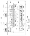
図1は、本発明の実施形態に係る情報処理装置を含むネットワーク環境の一例を示す図である。 FIG. 1 is a diagram illustrating an example of a network environment including an information processing apparatus according to an embodiment of the present invention.
MFP(Multifunction Peripheral)100は、画像データの入出力や送受信、それらに関連する各種の画像処理を行う情報処理装置である。 An MFP (Multifunction Peripheral) 100 is an information processing apparatus that performs input / output and transmission / reception of image data, and various image processing related thereto.
MFP100は、装置全体を制御するメインコントローラ101と、ユーザインタフェースである操作部102と、画像入力デバイスであるスキャナ部103と、画像出力デバイスであるプリンタ部104とを備える。
The MFP 100 includes a
メインコントローラ101は、操作部102、スキャナ部103、及びプリンタ部104に接続され、これら各部の動作を制御する。
The
MFP100は、LAN(Local Area Network)113上の無線LANアクセスポイント(AP)112(無線中継端末)との間で無線LAN接続する通信機能を備える。 The MFP 100 has a communication function for establishing a wireless LAN connection with a wireless LAN access point (AP) 112 (wireless relay terminal) on a LAN (Local Area Network) 113.
AP112は、LAN113を介してパーソナルコンピュータであるPC110,111に接続されている。
The AP 112 is connected to the PCs 110 and 111 that are personal computers via the
次に、図1におけるメインコントローラ101について図2を用いて説明する。
Next, the
図2は、図1におけるメインコントローラ101の概略構成を示すブロック図である。
FIG. 2 is a block diagram showing a schematic configuration of the
メインコントローラ101は、以下に説明する各部を備える。
The
CPU(Central Processing Unit)201は、システムバス207を介して、RAM(Random Access Memory)202、及びROM(Read Only Memory)203と接続される。また、CPU201は、システムバス207を介して、フラッシュメモリ204、イメージバスI/F205、操作部I/F206、有線LAN I/F208、モデム部209、及び無線LAN I/F224と接続される。
A CPU (Central Processing Unit) 201 is connected to a RAM (Random Access Memory) 202 and a ROM (Read Only Memory) 203 via a
RAM202は、CPU201の作業領域を提供するための随時読み書き可能なメモリである。RAM202は、画像データを一時記憶するための画像メモリとしても使用される。ROM203は、ブートROMであり、システムのブートプログラムが格納される。フラッシュメモリ204は、不揮発性メモリであり、MFP100の電源遮断後にも保持が必要なシステムソフトウェアや設定値データ等が格納される。
The
操作部I/F206は、例えば、液晶タッチパネル等を備える操作部102との間で入出力を行うためのインターフェースである。操作部I/F206は、操作部102に対して表示すべき画像データを出力し、また、ユーザが操作部102を介して入力した情報をCPU201に伝送するために使用される。
The operation unit I /
有線LAN I/F208は、LANと接続するためのインターフェースであり、LANに対して情報の入出力を行う。なお、このLANは、LAN113とは異なるものとする。モデム部209は、公衆回線と接続するためのインターフェースであり、公衆回線に対して情報の入出力を行う。
The wired LAN I /
イメージバスI/F205は、システムバス207と画像バス210とを接続するインターフェースであり、データ構造を変換するバスブリッジとして動作する。
The image bus I /
画像バス210には、RIP(Raster Image Processor)211、デバイスI/F212、スキャナ画像処理部213、プリンタ画像処理部214、画像回転部215、及び画像圧縮部216が接続される。
A RIP (Raster Image Processor) 211, a device I /
RIP211は、LAN等を介して外部から受信したPDL(Page Description Language)データをビットマップイメージに展開する。デバイスI/F212は、スキャナ部103及びプリンタ部104とメインコントローラ101とを接続するインターフェースであり、画像データの同期系/非同期系の変換を行う。
The
スキャナ画像処理部213は、スキャナ部103から読み込んだ入力画像データに対して、補正、加工、編集等の処理を行う。プリンタ画像処理部214は、プリンタ部104へ出力するプリント出力画像データに対して、色変換、フィルタ処理、解像度変換等の処理を行う。画像回転部215は、画像データの回転を行う。画像圧縮部216は、多値画像データに対してはJPEG圧縮伸長処理を行い、2値画像データに対してはJBIG、MMR、MHなどの圧縮伸長処理を行う。
The scanner
HDD(Hard Disk Drive)217は、不揮発なデータ記憶装置であり、画像データ、システムデータ、ユーザデータ等の各種データ、及びCPU201が実行する動作プログラムが保持される。メインコントローラ101が、HDD217を接続しない構成をとる場合は、上記各種データはフラッシュメモリ204に保持されるものとする。
An HDD (Hard Disk Drive) 217 is a non-volatile data storage device, and holds various data such as image data, system data, user data, and an operation program executed by the
電源制御部218は、電力供給手段である電源装置219から電力供給ライン220を介して受容したDC電源を、電力供給ライン221,222を介してメインコントローラ101内の主制御部240、副制御部241に供給する。
The power
主制御部240は、CPU201、ROM203、フラッシュメモリ204、イメージバスI/F205、RIP211、デバイスI/F212、スキャナ画像処理部213、プリンタ画像処理部214を備える。さらに、主制御部240は、画像回転部215、画像圧縮部216、HDD217を備える。
The
一方、副制御部241は、無線LAN I/F224、RAM202、操作部I/F206、有線LAN I/F208、及びモデム部209を備える。
On the other hand, the
電力供給ライン221は、主制御部240内の各部に接続される。電力供給ライン222は、副制御部241内の各部に接続される。
The
また、電源装置219は、不図示の大容量給電用の大電源回路と、不図示の小容量給電用の小電源回路との2系統の電源回路を備える。
The
電源制御部218は、副制御部241からの制御信号線223と、CPU201からの制御信号線225を介して制御信号を受信する。そして、受信した制御信号に基づいて各電力供給ライン221,222の電力供給制御を行う。また、電源制御部218は、後述するMFP100の電力状態に応じて電源回路を切り替えて給電制御を行う。
The power
無線LAN I/F224は、通信制御手段として、LAN113に接続されたAP112と接続するためにインターフェースである。無線LAN I/F224は、IEEE(Institute of Electrical and Electronic Enginerrs)が定めるIEEE802.11b/a/g/n等の規格が定める接続方式や通信速度に基づき無線通信を行う。メインコントローラ101は、この無線LAN I/F224によりAP112と無線接続することでLAN113に接続することができる。
The wireless LAN I /
このように、メインコントローラ101は、LANや公衆回線に接続され、有線LAN I/F208やモデム部209、無線LANI/F224を介して、外部機器との間で画像情報、デバイス情報、その他各種情報の入出力を行う。
As described above, the
MFP100は、装置の電力状態に応じて、通常電力モードと省電力モードの2つの動作モードを備える。
通常電力モードでは、CPU201は、電力供給ライン221と電力供給ライン222に対する電力供給が有効となるように電源制御部218を制御する。その結果、主制御部240と副制御部241の双方に電力が供給され、MFP100は通常状態(第一の電力状態)となる。
In the normal power mode, the
省電力モードでは、CPU201は、電力供給ライン222に対する電力供給が有効となるように、そして、電力供給ライン221に対する電力供給が無効となるように電源制御部218を制御する。その結果、主制御部240に対する電力供給は遮断され、MFP100は省電力状態(第二の電力状態)となる。省電力状態では、通常状態と比較してMFP100の消費電力を大幅に低減することができる。
In the power saving mode, the
省電力状態にあるMFP100では、例えば、AP112から印刷ジョブ等を受信した場合、無線LAN I/F224が電源制御部218を制御して、省電力状態から通常状態へ復帰させる。なお、省電力状態から通常状態への復帰は、無線LAN I/224のデータ受信に限るものではなく、有線LAN I/F208のデータ受信やモデム部209のFAX受信や操作部102が備える不図示のボタン押下を起因として復帰できるものとする。
In the
省電力状態では、RAM202にも電力が供給されるので、RAM202はセルフリフレッシュ動作してシステムプログラムのバックアップを行う。これにより、省電力状態から通常状態へ復帰すると、RAM202上にシステムプログラムが速やかに展開されて、状態復帰を迅速に行うことができる。
In the power saving state, since power is also supplied to the
なお、省電力モードでは、CPU201を含む主制御部240に対する電力供給が遮断されるものとしたが、これに限るものではない。例えば、他の態様として、主制御部240に対する電力供給を遮断することなく、通常電力モード時よりも低電力状態にある電力状態を省電力状態としてもよい。このとき、省電力モードでは、通常電力モードと比較してCPU201の動作周波数を下げる必要があり、CPU201の単位時間当たりの処理性能が低下する。よって、省電力モードとして電力供給を低減した場合でも、電力遮断時と同様、例えば多数のパケット受信により省電力モードでは処理できずに通常状態へ復帰してパケット応答処理すべき状況が発生する。
In the power saving mode, power supply to the
次に、図2における無線LAN I/F224の詳細な構成について図3を用いて説明する。
Next, a detailed configuration of the wireless LAN I /
図3は、図2における無線LAN I/F224の詳細な構成を示すブロック図である。
FIG. 3 is a block diagram showing a detailed configuration of the wireless LAN I /
無線LAN I/F224は、CPU301と、ROM302と、RAM303と、無線送受信部304と、アンテナ305と、ホストI/F306とを備えるサブシステムで構成される。
The wireless LAN I /
CPU301は、無線LAN I/F224の主制御を司る。ROM302には、メインコントローラ101の起動シーケンスにより無線LAN I/F224が起動したときに実行されるブートプログラム、及びCPU301が実行する動作プログラムが保持される。
The
CPU301は、ROM302に保持された動作プログラムに基づき無線LAN I/F224を制御する。
The
RAM303は、CPU301のワークメモリとして使用される。また、RAM303には、AP112と無線接続するための各種管理情報として、通信方式、認証方式、MAC(Media Access Control)アドレス、IP(Internet Protocol)アドレス等が保持される。更に、RAM303には、MFP100が省電力状態時に応答可能な通信要求を判別するためのパケットパターン(比較情報)が保持される。本実施形態では、このパケットパターンは、MFP100が通常状態から省電力状態への移行時にメインコントローラ101のCPU201の指示でRAM202からRAM303へ転送されるものとする。
A
無線送受信部304は、アンテナ305に接続され、無線接続時のデータ送受信に用いられる搬送波の変復調処理に伴う物理的、電気的処理を行う。
The wireless transmission /
ホストI/F306は、システムバス207と接続するためのバス変換処理部である。ホストI/F306は、例えば、SDIO(Secure Digital Input/Output)やUSB(Universal Serial Bus)等の汎用インターフェースで構成される。
The host I /
無線LAN I/F224は、さらに、不図示のDMA(Direct Memory Access)を備え、ホストI/F306を介して、RAM303とメインコントローラ101内のRAM202との間でデータ送受信を行う。
The wireless LAN I /
次に、AP112の詳細な構成について図4を用いて説明する。
Next, a detailed configuration of the
図4は、AP112の詳細な構成を示すブロック図である。
FIG. 4 is a block diagram showing a detailed configuration of the
AP112は、CPU401と、ROM402と、RAM403と、無線送受信部404と、アンテナ405と、有線送受信部406とを備える。
The
CPU401は、AP112の主制御を司る。ROM402には、AP112の起動時に実行されるブートプログラム、及びCPU401が実行する動作プログラムが保持される。
The
RAM403は、CPU401のワークメモリとして使用される。また、RAM403には、MFP100と無線接続するための各種管理情報として、通信方式、認証方式、各種アドレス情報等を保持する。
The
無線送受信部404は、アンテナ405に接続され、無線接続時のデータ送受信に用いられる搬送波の変調及び復調処理を行う。有線送受信部406は、不図示のMAC(Media Access Control)制御部とPHYとを備え、LANとの有線接続に必要な物理的、電気的な処理を行う。
The wireless transmission /
次に、MFP100がAP112に無線LAN接続するときに実行される処理について図5を参照して説明する。
Next, processing executed when
本実施形態では、AP112は、IEEE802.11v規格に規定されたARP(Address Resolution Protocol)プロキシ機能に対応し、当該ARPプロキシ機能が有効化されているものとする。AP112は、ARP要求を受信したときに、上述した管理情報に基づきARP要求の宛先のIPアドレスを備える機器(例えばMFP100)の接続有無を判定する。そして、接続有りと判定した場合は、当該機器の代理でARP要求に応答し、当該機器のMACアドレスをARP要求の送信元に通知する。
In this embodiment, the
MFP100は、ARPプロキシ機能に対応するAP112に無線LAN接続し、ARPプロキシ機能の提供の有無に応じて、省電力状態で応答可能な通信要求を判別するパケットパターンを変更する。
The
図5は、MFP100とAP112との間の無線接続時の動作の流れを示すシーケンス図である。なお、図示の処理はMFP100がAP112への接続試行時に開始されるものとする。また、MFP100での処理は、CPU201が無線LAN I/F224を制御して行うものとする。
FIG. 5 is a sequence diagram showing a flow of operation during wireless connection between
図5において、AP112は、ビーコンフレームを用いてアクセスポイント識別情報をブロードキャストで送信する(501)。
In FIG. 5, the
MFP100は、ビーコンフレームを一定時間受信後、ビーコンフレーム記載のアクセスポイント識別情報に基づいてアクセスポイントを探索する(502)。該当するアクセスポイントの探索に成功すると、受信したアクセスポイント識別情報に基づき探索したアクセスポイント宛てに認証種別に応じた事前共有鍵情報を認証要求として送信する(503)。
After receiving the beacon frame for a predetermined time, the
AP112は、受信した事前共有鍵情報が正しければ接続可とし、間違っている場合は接続不可として認証応答を行う(504)。なお、アクセスポイント識別情報に認証設定が無い場合は認証処理を行わない。
If the received pre-shared key information is correct, the
次に、MFP100は、アクセスポイントに接続するためにアソシエーション要求を送信する(505)。
Next, the
AP112は、アソシエーション要求に対して接続許可のアソシエーション応答を送信して接続が完了する(506)。AP112はARPプロキシ機能に対応することから、アソシエーション応答時にARPプロキシ対応情報を併せて送信する。具体的には、IEEE802.11v規格で規定される拡張Capability Fieldが備えるProxy ARP Serviceのビット値を1としてアソシエーション応答を行う。
In response to the association request, the
アソシエーション応答を受信したMFP100は、応答情報内のARPプロキシ対応情報に応じて、自身が接続する無線LANアクセスポイントがARPプロキシ機能対応か否かを判定する(507)。そして、省電力状態で応答可能なパケットか否かを判別するためのパケットパターンを変更する(507)。このARPプロキシ判定処理の詳細は後述する。アソシエーション応答が終了した後、MFP100とAP112とはデータ送受信が可能となる(508)。
Receiving the association response, the
次に、MFP100にて実行されるARPプロキシ判定処理(図5の507)の詳細について図6を用いて説明する。
Next, details of the ARP proxy determination process (507 in FIG. 5) executed in
図6は、MFP100にて実行されるARPプロキシ判定処理の詳細を示すフローチャートである。なお、本処理は、無線LAN I/F224が、アソシエーション応答で受信したデータをメインコントローラ101のRAM202へ転送し、転送終了をメインコントローラ101のCPU201が検出した後に開始されるものとする。また、本処理は、CPU201がRAM202上に展開された動作プログラムに基づき実行されるものとする。
FIG. 6 is a flowchart showing details of the ARP proxy determination process executed in
まずステップS601では、CPU201は、RAM202に格納された受信済みアソシエーション応答の拡張Capability Fieldを取得する。
First, in step S <b> 601, the
次に、ステップS602では、CPU201は、読み出した拡張Capability FieldのProxy ARP Serviceのビット値を参照する。
Next, in step S602, the
次に、ステップS603では、CPU201は、ステップS602で参照したビット値が1であるか否かを判定する。Proxy ARP Serviceのビット値が1であると判定した場合はステップS604に移行する。一方、ステップS603でProxy ARP Serviceのビット値が1でないと判定した場合、パケットパターンの変更を行わずに本処理を終了する。
Next, in step S603, the
ステップS604では、CPU201は、省電力状態で応答可能な通信要求かを判別するためのパケットパターンファイルからARPプロキシに対応するパターン(以下、「ARPプロキシパターン」とも呼ぶ)を削除して、本処理を終了する。ステップS604におけるARPプロキシパターン削除処理の詳細は後述する。
In step S604, the
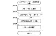
次に、図6のステップS604におけるARPプロキシパターン削除処理の詳細について図7を用いて説明する。 Next, details of the ARP proxy pattern deletion processing in step S604 in FIG. 6 will be described with reference to FIG.
図7は、図6のステップS604におけるARPプロキシパターン削除処理の詳細を示すフローチャートである。なお、本処理は、CPU201がRAM202上に展開された動作プログラムに基づき実行されるものとする。
FIG. 7 is a flowchart showing details of the ARP proxy pattern deletion process in step S604 of FIG. Note that this processing is executed by the
まずステップS701では、CPU201は、RAM202に格納されたパケットパターンに対応するアドレスを参照して現在のパケットパターンファイルを取得する。
First, in step S701, the
次に、ステップS702では、CPU201は、取得したパケットパターンファイルを参照し、ARPプロキシに対応するパターンの有無を判定する。ARPプロキシに対応するパターンがないと判定した場合、パケットパターンから何も削除せずに本処理を終了する。一方、ステップS702でARPプロキシに対応するパターンがあると判定した場合、CPU201は、パケットパターンファイルからARPプロキシに対応するパターンを削除する(ステップS703)。つづいて、ステップS704において、CPU201は、削除したARPプロキシパターンの代わりとなるパケットパターンを追加変更して、リターンする。
Next, in step S702, the
図8(a)は、MFP100に保持される初期状態のパケットパターンの一例を示す図である。
FIG. 8A is a diagram illustrating an example of an initial state packet pattern held in the
図8(a)において、パケットパターン800は、各種通信要求に対応するパケットパターンを最大3つ保持する。図示例では、ARP要求用パターン801、SNMP要求用パターン802、及び自装置宛て要求用パターン803の3パターンが保持される。また、初期状態のパケットパターン800には、通信要求の種類別に設定された通信要求受信時の動作設定804と、パターンの有効/無効を示す設定805とを備える。ここで、SNMP要求用パターン802は、Windows(登録商標)がサポートするプリンタ管理用MIB(Management Information Base)を有する。
In FIG. 8A, a
パターン判定は、ID806に示す番号の昇順に高い優先度で行うものとし、受信した通信要求に対して、まずIDが1のARP要求用パターンと比較し、一致しなければ次のIDが2のSNMP要求用パターンの比較を行う。
The pattern judgment is performed in the ascending order of the numbers shown in the
省電力状態のMFP100は、初期状態のパケットパターンを用いることでARP要求やSNMP要求の受信を判別し、機器自体を通常状態に復帰させることなく、無線LAN I/F224内のCPU301が応答処理を行う。一方、ARP要求やSNMP要求と異なり、自装置宛ての通信要求を受信したときは、MFP100が省電力状態から通常状態へ復帰した後にメインコントローラ101内のCPU201が応答処理を行う。
The power-saving
図8(b)は、図8(a)に示すARP要求用パターン801の詳細を示す図である。
FIG. 8B is a diagram showing details of the
図8(b)において、ARP要求用パターン801は、宛先のMACアドレス情報である宛先Etherアドレスと、プロトコル識別用のフレームタイプ及びプロトコルタイプと、パケット内容を示すオペレーションとを備える。各項目は、比較文字列を示すパターン列810と、パターン列810のバイト長811とを備える。なお、パターンが備える項目は図示例に限定されるものではなく、発信元アドレス等の項目追加やプロトコルタイプ項目の削除等、応答すべき通信要求を判別できる範囲で変更してもよい。
In FIG. 8B, the
また、各項目は、いずれもRFC(Request For Comment)で規定されるパケットフレーム上の所定のデータ位置で定義される。無線LAN I/F224内のCPU301は、受信したパケットが格納されたRAM303の先頭アドレスに基づき、RFCの定義に基づく所定のオフセット分のデータ位置からバイト長811分のデータを参照することで、各項目を取得できる。各項目で定義されるパターン列810と対応する取得データとを比較し、全ての項目が一致すると、通信要求受信時の動作設定804で設定された処理が行われる。
Each item is defined at a predetermined data position on a packet frame defined by RFC (Request For Comment). The
本実施形態では、図7のステップS703のARPプロキシパターン削除処理により、図8(c)に示すパケットパターン820が得られる。その後、図7のステップS704のパターン追加変更により、SNMP要求用パターン802のIDはそのままとし、図9(d)に示すように、固有MIBを備える新たなSNMP要求用パターン831がID2に追加される。さらに、自装置宛て要求用パターン803のIDがID2からID3に変更される。これにより、図9(d)に示す変更後のパケットパターン830が得られる。
In the present embodiment, the
図7のステップS704におけるパターン追加変更の処理では、MFP100が通常状態で受信する通信要求に対して、図9(e)に示すようなカウントテーブル840(受信頻度テーブル)に基づいて行われるものとする。カウントテーブル840は、通信要求の種類別の受信回数を示すテーブル情報である。
In the pattern addition / change process in step S704 of FIG. 7, the communication request received by the
具体的には、SNMP要求用パターン802は、カウントテーブル840を参照すると最も受信回数が多いことから、最も優先度が高いID1に変更される。また、カウントテーブル840で受信回数が2番目に多いSNMP要求用パターン831(固有MIB2)がID2として追加される。
Specifically, the
図9(d)に示すようなパターン追加変更後のパケットパターン830を用いることで、MFP100は、省電力状態で受信するSNMP及び固有MIBを備えるSNMPを判別して応答することができる。さらに、自装置宛ての通信要求(自装置宛て要求用パターン)受信時には、省電力状態から通常状態に復帰して処理を継続することができる。
By using the
なお、ARPプロキシパターン削除処理は、上記に限定されるものではない。例えば、ステップS703でARPプロキシパターンを削除した後、ステップS704のパターン追加変更でパターンを追加しなくてもよい。この場合、図7に示す処理フローにより図8(c)に示すパケットパターン820が得られる。このとき、MFP100は、省電力状態で受信するSNMPに応答でき、自装置宛ての通信要求受信時には通常状態に起動して処理を継続することができる。
The ARP proxy pattern deletion process is not limited to the above. For example, after deleting the ARP proxy pattern in step S703, it is not necessary to add a pattern in the pattern addition change in step S704. In this case, the
次に、省電力状態のMFP100がPC110から受信したARP要求に応答した後、後続するSNMP要求に応答する処理について図10を用いて説明する。
Next, processing in which the
図10は、PC110とMFP100とAP112との間のデータ通信処理の流れを示すシーケンス図である。なお、図示の処理では、MFP100が通常状態にあり、PC110がMFP100のMACアドレスを解決できてない状態にあって、MFP100とAP112とが接続した状態で開始される。また、MFP100は、PC110にデバイス登録済みとする。
FIG. 10 is a sequence diagram showing a flow of data communication processing among the
MFP100は、通常状態から省電力状態へ移行する(900)。省電力状態への移行要因としては、CPU201が、メインコントローラ101内のタイマー(不図示)を利用し、所定時間内に通信要求の受信や操作部102への操作が無いことを検出した場合が挙げられる。さらに、CPU201が、操作部102が備える不図示の省電力状態移行ボタンの押下を検出した場合が挙げられる。
The
また、MFP100が通常状態から省電力状態に移行した際に、CPU201の指示によりパケットパターンファイルが無線LAN I/F224内のRAM303へ転送され、CPU301が参照できる状態となる。
Further, when the
MFP100が省電力状態へ移行した後、例えば、Windows(登録商標)を備えるPC110が、既に使用デバイスとして登録済みのMFP100に対して、所定時間間隔で生存確認するために管理用SNMP要求を送信する(901)。
After the
次に、PC110は、自身が備える不図示のプロトコルスタックのARPテーブル上にMFP100のMACアドレスが無いことを確認し、MFP100のMACアドレス解決用ARP要求をブロードキャスト送信する(902)。
Next, the
上記MFP100のMACアドレス解決用ARP要求を受信したAP112は、RAM403に保持している接続済み機器の管理情報に基づき、ARP要求の宛先のIPアドレスを備える機器が存在するか否かを判定する(903)。本実施形態では、ARP要求宛先のIPアドレスは、MFP100のIPアドレスと一致する。よって、AP112は、ARPプロキシ機能によりARP要求に代理で応答し、PC110へMFP100のMACアドレスを通知する(904)。
The
PC110は、ARP応答を受信してMFP100のMACアドレスを解決し(905)、MFP100宛てにSNMP要求を送信する(906)。SNMP要求は、AP112を経てMFP100に送信される(907)。
The
MFP100は、パケットパターン830に基づき無線LAN I/F224で受信したSNMP要求を自装置宛ての通信要求と判定し、省電力状態を維持したままSNMP要求に応答する(908)。
The
SNMP要求に対する応答は、AP112を経て(909)、PC110へ到達し(910)、MFP100の生存確認が成功する。
The response to the SNMP request passes through the AP 112 (909), reaches the PC 110 (910), and the survival confirmation of the
なお、上述したSNMP要求は、Windows(登録商標)が用いるSNMPに限定されず、例えば、他のデバイス管理系アプリケーションが用いる固有MIBを備えるSNMPであってもよい。この場合でも、MFP100は、図7に示す処理で追加変更された固有MIBを備えるSNMP要求用パターン831を用いて応答可能な通信要求と判断し、省電力状態を維持したまま応答することができる。
The SNMP request described above is not limited to the SNMP used by Windows (registered trademark), and may be, for example, an SNMP provided with a unique MIB used by another device management system application. Even in this case, the
また、パケットパターン830は、MFP100が通常動作状態時に操作部102で確認できるように構成されてもよい。
Further, the
図11(a)及び図11(b)は、操作部102の液晶タッチパネル上に表示されるネットワーク設定画面の一例を示す図である。図示の画面は、MFP100が通常状態時にユーザが操作部102で所定のメニュー操作を行うことで表示されるものとする。
FIGS. 11A and 11B are diagrams illustrating an example of a network setting screen displayed on the liquid crystal touch panel of the
図11(a)に示す設定画面1000には、図6に示すARPプロキシ判定処理の結果に基づき、MFP100がARPプロキシに対応するAP112に接続しているか否かを示すウィンドウ1001が表示されている。図示例では、ARPプロキシに対応する無線LANアクセスポイントに接続している旨が表示されている。一方、図6のステップS603の判定結果がNOであった場合は、ARPプロキシに対応していない無線LANアクセスポイントに接続している旨が表示される。
A
図11(b)に示す設定画面1000には、図7に示すARPプロキシパターン削除処理にて決定されたパケットパターン830に基づき、MFP100が省電力状態で応答する通信要求種別の選択ウィンドウ1010が表示されている。
A setting
選択ウィンドウ1010では、カウントテーブル840に基づく情報として、各SNMPの受信回数と、省電力状態での応答の有効/無効が表示される(1011)。また、残り有効設定数1012には、有効設定上限が表示される。有効/無効の設定は、操作部102における不図示の所定のメニュー操作で変更できてもよく、本実施形態では、残り有効設定数1012が0であり、既に有効設定されているSNMPを無効化すれば他のSNMPを有効設定できる。
In the
以上説明したように、MFP100は、受信する通信要求に対してAP112が自装置の代理で応答可能か否かを判別し、その結果に基づいて、省電力状態での通信要求の種類を判別するためのパケットパターンを変更する。そして、省電力状態時には、変更されたパケットパターンを利用することで、追加されたパケットパターン分だけより多くの通信要求に対する応答処理が可能となる。その結果、より長く省電力状態を維持することができ、情報処理装置の更なる省電力化を実現することができる。
As described above, the
なお、上述した実施形態は本発明を限定するものではない。例えば、図7に示すARPプロキシパターン削除処理により、ARPプロキシに対応するパターンを削除したパケットパターン820を得てもよい。この場合でも、AP112のARPプロキシ機能により、情報処理装置は省電力状態においてARP要求の応答処理を行うことなく省電力状態を維持しつつSNMP要求にも応答できる。即ち、冗長となるARPRパターン削除した少サイズのパケットパターン820を用いることで、従来の省電力状態での通信要求に対する応答処理機能を落とすことなく、パケットパターンの転送処理負荷や保持に要するメモリ容量を低減することができる。
In addition, embodiment mentioned above does not limit this invention. For example, the
また、上述した実施形態において、MFP100が省電力状態で応答するパケットパターンの削除はARP要求に対応するパターンに限定するものではない。即ち、MFP100が接続するAP112が応答でき、かつ、MFP100が省電力状態で応答可能な通信要求に対応するものであれば、如何なるパターンであってもよい。
Further, in the above-described embodiment, the deletion of the packet pattern to which the
更には、上述した実施形態において、ARPプロキシに対応するパターン削除後にMFP100が接続するAP112のARPプロキシ機能が利用できなくなった場合は、ARPプロキシに対応するパターンを再設定してもよい。これにより、例えば、他のARPプロキシ機能非対応の無線LANアクセスポイントに再接続する際は、初期状態のパケットパターン800を用いることで、MFP100は省電力状態でARP応答することができる。
Furthermore, in the above-described embodiment, when the ARP proxy function of the
また、本発明は、以下の処理を実行することによっても実現される。即ち、上述した実施形態の機能を実現するソフトウェア(プログラム)を、ネットワーク又は各種記憶媒体を介してシステム或いは装置に供給し、そのシステム或いは装置のコンピュータ(またはCPUやMPU等)がプログラムを読み出して実行する処理である。 The present invention can also be realized by executing the following processing. That is, software (program) that realizes the functions of the above-described embodiments is supplied to a system or apparatus via a network or various storage media, and a computer (or CPU, MPU, or the like) of the system or apparatus reads the program. It is a process to be executed.
100 複合機(MFP)
101 メインコントローラ
112 無線LANアクセスポイント(AP)
224 無線LAN I/F
301,401 CPU
304,404 無線送受信部
800,820,830 パケットパターン
100 MFP (MFP)
101
224 Wireless LAN I / F
301,401 CPU
304, 404
Claims (8)
前記情報処理装置が省電力モードで動作する場合に、応答条件に従って前記省電力モードを維持したまま受信パケットに応答する応答手段と、
前記情報処理装置の代わりに受信パケットに応答する応答機能を前記中継装置が有しているか否かを判定する判定手段と、
前記応答機能を前記中継装置が有していると前記判定手段によって判定された場合に、前記応答条件を変更する変更手段とを備えることを特徴とする情報処理装置。 An information processing device capable of communicating with an external device via a relay device ,
A response means for responding to a received packet while maintaining the power saving mode according to a response condition when the information processing apparatus operates in a power saving mode;
Determining means for determining whether or not the relay device has a response function for responding to a received packet instead of the information processing device;
Wherein when the response function is determined by said determining means and said relay device has an information processing apparatus characterized by comprising a changing means for changing the response condition.
前記応答手段は、前記受信パケットが前記複数のパケットパターンのいずれかに一致する場合に、前記省電力モードを維持したまま前記受信パケットに応答し、
前記変更手段は、前記複数のパケットパターンのうち、前記中継装置が有する前記応答機能に対応するパケットパターンを削除することを特徴とする請求項1に記載の情報処理装置。 The response condition indicates a plurality of packet patterns,
The response means responds to the received packet while maintaining the power saving mode when the received packet matches any of the plurality of packet patterns.
The information processing apparatus according to claim 1, wherein the changing unit deletes a packet pattern corresponding to the response function of the relay apparatus from the plurality of packet patterns .
前記変更手段は、前記複数のパケットパターンのうち、前記ARP要求に対応するパケットパターンを削除することを特徴とする請求項2又は3に記載の情報処理装置。 The response function is a function in which the relay device responds to an ARP request instead of the information processing device,
The information processing apparatus according to claim 2 , wherein the changing unit deletes a packet pattern corresponding to the ARP request from the plurality of packet patterns .
前記情報処理装置が省電力モードで動作する場合に、応答条件に従って前記省電力モードを維持したまま受信パケットに応答する応答工程と、
前記情報処理装置の代わりに受信パケットに応答する応答機能を前記中継装置が有しているか否かを判定する判定工程と、
前記応答機能を前記中継装置が有していると前記判定工程で判定された場合に、前記応答条件を変更する変更工程とを備えることを特徴とする情報処理装置。 An information processing apparatus control method capable of communicating with an external apparatus via a relay apparatus ,
When the information processing apparatus operates in a power saving mode, a response step of responding to a received packet while maintaining the power saving mode according to a response condition;
A determination step of determining whether or not the relay device has a response function for responding to a received packet instead of the information processing device;
An information processing apparatus comprising: a changing step of changing the response condition when it is determined in the determination step that the relay device has the response function .
Priority Applications (2)
| Application Number | Priority Date | Filing Date | Title |
|---|---|---|---|
| JP2013073048A JP6112938B2 (en) | 2013-03-29 | 2013-03-29 | Information processing apparatus, control method therefor, and program |
| US14/225,685 US9625975B2 (en) | 2013-03-29 | 2014-03-26 | Information processing apparatus capable of connecting to network in power saving state, method of controlling the same, and storage medium |
Applications Claiming Priority (1)
| Application Number | Priority Date | Filing Date | Title |
|---|---|---|---|
| JP2013073048A JP6112938B2 (en) | 2013-03-29 | 2013-03-29 | Information processing apparatus, control method therefor, and program |
Publications (3)
| Publication Number | Publication Date |
|---|---|
| JP2014197333A JP2014197333A (en) | 2014-10-16 |
| JP2014197333A5 JP2014197333A5 (en) | 2016-07-28 |
| JP6112938B2 true JP6112938B2 (en) | 2017-04-12 |
Family
ID=51622050
Family Applications (1)
| Application Number | Title | Priority Date | Filing Date |
|---|---|---|---|
| JP2013073048A Expired - Fee Related JP6112938B2 (en) | 2013-03-29 | 2013-03-29 | Information processing apparatus, control method therefor, and program |
Country Status (2)
| Country | Link |
|---|---|
| US (1) | US9625975B2 (en) |
| JP (1) | JP6112938B2 (en) |
Families Citing this family (10)
| Publication number | Priority date | Publication date | Assignee | Title |
|---|---|---|---|---|
| JP5835291B2 (en) * | 2013-09-05 | 2015-12-24 | コニカミノルタ株式会社 | COMMUNICATION DEVICE, ITS CUSTOMIZATION METHOD, AND COMPUTER PROGRAM |
| JP6464768B2 (en) * | 2015-01-21 | 2019-02-06 | 富士ゼロックス株式会社 | Response device and program |
| US20160227097A1 (en) * | 2015-02-04 | 2016-08-04 | Casio Computer Co., Ltd. | Data processing device that executes predetermined data processing by linking with other apparatus |
| JP6376109B2 (en) * | 2015-11-19 | 2018-08-22 | 京セラドキュメントソリューションズ株式会社 | Information processing apparatus and program |
| KR102375847B1 (en) * | 2015-12-04 | 2022-03-18 | 삼성전자 주식회사 | ELECTRONIC DEVICE AND METHOD OF PROVIDING INFORMATION ABOUT THE AP((access point) |
| JP6634894B2 (en) | 2016-03-07 | 2020-01-22 | コニカミノルタ株式会社 | Image processing apparatus, control method thereof, and program |
| WO2017177030A1 (en) * | 2016-04-06 | 2017-10-12 | Emerge Print Management, Llc | Apparatus and method for metering and monitoring printer related data on-networked printers |
| US10244477B2 (en) | 2016-08-01 | 2019-03-26 | Ricoh Company, Ltd. | Communication apparatus, communication terminal, and communication system |
| US11405519B2 (en) * | 2020-03-06 | 2022-08-02 | Oki Data Corporation | Information processing apparatus and information processing method |
| JP2022003742A (en) | 2020-06-23 | 2022-01-11 | 株式会社リコー | Electronic device, control method thereof, and program |
Family Cites Families (6)
| Publication number | Priority date | Publication date | Assignee | Title |
|---|---|---|---|---|
| US7916687B2 (en) * | 2006-03-03 | 2011-03-29 | Qualcomm Incorporated | Standby time improvements |
| JP5064995B2 (en) * | 2007-12-20 | 2012-10-31 | キヤノン株式会社 | Data processing apparatus, data processing method, and program |
| JP5341630B2 (en) | 2009-06-15 | 2013-11-13 | キヤノン株式会社 | Data processing apparatus and data processing method |
| JP5436176B2 (en) * | 2009-12-04 | 2014-03-05 | キヤノン株式会社 | Information processing apparatus and control method thereof |
| JP4861539B1 (en) * | 2010-06-02 | 2012-01-25 | パナソニック株式会社 | Communication control apparatus and packet filtering method |
| JP5704904B2 (en) * | 2010-11-29 | 2015-04-22 | キヤノン株式会社 | DATA PROCESSING DEVICE, DATA PROCESSING DEVICE CONTROL METHOD, AND PROGRAM |
-
2013
- 2013-03-29 JP JP2013073048A patent/JP6112938B2/en not_active Expired - Fee Related
-
2014
- 2014-03-26 US US14/225,685 patent/US9625975B2/en not_active Expired - Fee Related
Also Published As
| Publication number | Publication date |
|---|---|
| US9625975B2 (en) | 2017-04-18 |
| JP2014197333A (en) | 2014-10-16 |
| US20140298054A1 (en) | 2014-10-02 |
Similar Documents
| Publication | Publication Date | Title |
|---|---|---|
| JP6112938B2 (en) | Information processing apparatus, control method therefor, and program | |
| US11792632B2 (en) | Communicating apparatus, communication method, and storage medium storing program | |
| US20170359251A1 (en) | Communication apparatus, control method therefor, and computer-readable storage medium | |
| US9641713B2 (en) | Apparatus and method for deactivating power-saving mode, relay device, and computer-readable storage medium for computer program | |
| US9172834B2 (en) | Image forming system and method for recovering image forming apparatus from three different power saving modes | |
| US9516596B2 (en) | Apparatus and method | |
| CN105848191B (en) | Communication apparatus and control method | |
| JP6218563B2 (en) | Information processing apparatus, setting change method, and program | |
| JP2015106798A (en) | Communication device, communication system, control method and program of communication device | |
| US10389703B2 (en) | Communication apparatus and communication method | |
| JP2017208775A (en) | Communication device, control method therefor and program | |
| JP6700972B2 (en) | Communication device, control method, and program | |
| JP6212280B2 (en) | COMMUNICATION DEVICE, COMMUNICATION METHOD, AND PROGRAM | |
| US10306455B2 (en) | Communication apparatus, communication method, and non-transitory computer-readable storage medium | |
| JP6766551B2 (en) | Image processing device | |
| JP2016045697A (en) | Print control unit, printing system, control method of print control unit, and program | |
| JP6302169B2 (en) | COMMUNICATION DEVICE, COMMUNICATION METHOD, AND PROGRAM | |
| JP6484357B2 (en) | Communication apparatus and program | |
| JP5774163B2 (en) | COMMUNICATION DEVICE, COMMUNICATION DEVICE CONTROL METHOD, AND PROGRAM | |
| JP2002300360A (en) | Image communication unit | |
| JP2013258734A (en) | Image forming apparatus and restoration method |
Legal Events
| Date | Code | Title | Description |
|---|---|---|---|
| A621 | Written request for application examination |
Free format text: JAPANESE INTERMEDIATE CODE: A621 Effective date: 20160328 |
|
| A521 | Written amendment |
Free format text: JAPANESE INTERMEDIATE CODE: A523 Effective date: 20160608 |
|
| TRDD | Decision of grant or rejection written | ||
| A01 | Written decision to grant a patent or to grant a registration (utility model) |
Free format text: JAPANESE INTERMEDIATE CODE: A01 Effective date: 20170214 |
|
| A61 | First payment of annual fees (during grant procedure) |
Free format text: JAPANESE INTERMEDIATE CODE: A61 Effective date: 20170314 |
|
| R151 | Written notification of patent or utility model registration |
Ref document number: 6112938 Country of ref document: JP Free format text: JAPANESE INTERMEDIATE CODE: R151 |
|
| LAPS | Cancellation because of no payment of annual fees |