JP6112783B2 - Package - Google Patents
Package Download PDFInfo
- Publication number
- JP6112783B2 JP6112783B2 JP2012131295A JP2012131295A JP6112783B2 JP 6112783 B2 JP6112783 B2 JP 6112783B2 JP 2012131295 A JP2012131295 A JP 2012131295A JP 2012131295 A JP2012131295 A JP 2012131295A JP 6112783 B2 JP6112783 B2 JP 6112783B2
- Authority
- JP
- Japan
- Prior art keywords
- cartridge
- packing
- frame
- packing member
- opening
- Prior art date
- Legal status (The legal status is an assumption and is not a legal conclusion. Google has not performed a legal analysis and makes no representation as to the accuracy of the status listed.)
- Active
Links
- 238000012856 packing Methods 0.000 claims description 152
- 238000004806 packaging method and process Methods 0.000 claims description 18
- 238000004140 cleaning Methods 0.000 description 43
- 238000012546 transfer Methods 0.000 description 30
- 238000000034 method Methods 0.000 description 21
- 230000008569 process Effects 0.000 description 20
- 230000001105 regulatory effect Effects 0.000 description 17
- 239000005022 packaging material Substances 0.000 description 15
- 238000003860 storage Methods 0.000 description 9
- 239000011162 core material Substances 0.000 description 6
- 230000006870 function Effects 0.000 description 5
- 239000000463 material Substances 0.000 description 5
- 230000015572 biosynthetic process Effects 0.000 description 4
- 238000011161 development Methods 0.000 description 4
- -1 polyethylene terephthalate Polymers 0.000 description 4
- 239000002699 waste material Substances 0.000 description 4
- 230000004308 accommodation Effects 0.000 description 3
- 230000008878 coupling Effects 0.000 description 3
- 238000010168 coupling process Methods 0.000 description 3
- 238000005859 coupling reaction Methods 0.000 description 3
- 230000005489 elastic deformation Effects 0.000 description 3
- 238000012423 maintenance Methods 0.000 description 3
- 239000004033 plastic Substances 0.000 description 3
- 229920003023 plastic Polymers 0.000 description 3
- 238000003825 pressing Methods 0.000 description 3
- 239000011347 resin Substances 0.000 description 3
- 229920005989 resin Polymers 0.000 description 3
- 210000000707 wrist Anatomy 0.000 description 3
- 239000004743 Polypropylene Substances 0.000 description 2
- 230000005484 gravity Effects 0.000 description 2
- 238000001746 injection moulding Methods 0.000 description 2
- 239000000203 mixture Substances 0.000 description 2
- 238000000465 moulding Methods 0.000 description 2
- 239000002985 plastic film Substances 0.000 description 2
- 229920006255 plastic film Polymers 0.000 description 2
- 229920000139 polyethylene terephthalate Polymers 0.000 description 2
- 239000005020 polyethylene terephthalate Substances 0.000 description 2
- 229920001155 polypropylene Polymers 0.000 description 2
- 230000001681 protective effect Effects 0.000 description 2
- 238000007666 vacuum forming Methods 0.000 description 2
- 239000000853 adhesive Substances 0.000 description 1
- 238000013459 approach Methods 0.000 description 1
- 239000003086 colorant Substances 0.000 description 1
- 238000007599 discharging Methods 0.000 description 1
- 230000000694 effects Effects 0.000 description 1
- 238000005304 joining Methods 0.000 description 1
- 238000004519 manufacturing process Methods 0.000 description 1
- 230000007246 mechanism Effects 0.000 description 1
- 239000002184 metal Substances 0.000 description 1
- 230000002093 peripheral effect Effects 0.000 description 1
- 238000011112 process operation Methods 0.000 description 1
- 230000004044 response Effects 0.000 description 1
- 238000011144 upstream manufacturing Methods 0.000 description 1
- 238000003466 welding Methods 0.000 description 1
Images


Classifications
-
- G—PHYSICS
- G03—PHOTOGRAPHY; CINEMATOGRAPHY; ANALOGOUS TECHNIQUES USING WAVES OTHER THAN OPTICAL WAVES; ELECTROGRAPHY; HOLOGRAPHY
- G03G—ELECTROGRAPHY; ELECTROPHOTOGRAPHY; MAGNETOGRAPHY
- G03G21/00—Arrangements not provided for by groups G03G13/00 - G03G19/00, e.g. cleaning, elimination of residual charge
- G03G21/16—Mechanical means for facilitating the maintenance of the apparatus, e.g. modular arrangements
- G03G21/1661—Mechanical means for facilitating the maintenance of the apparatus, e.g. modular arrangements means for handling parts of the apparatus in the apparatus
- G03G21/1671—Mechanical means for facilitating the maintenance of the apparatus, e.g. modular arrangements means for handling parts of the apparatus in the apparatus for the photosensitive element
-
- B—PERFORMING OPERATIONS; TRANSPORTING
- B65—CONVEYING; PACKING; STORING; HANDLING THIN OR FILAMENTARY MATERIAL
- B65D—CONTAINERS FOR STORAGE OR TRANSPORT OF ARTICLES OR MATERIALS, e.g. BAGS, BARRELS, BOTTLES, BOXES, CANS, CARTONS, CRATES, DRUMS, JARS, TANKS, HOPPERS, FORWARDING CONTAINERS; ACCESSORIES, CLOSURES, OR FITTINGS THEREFOR; PACKAGING ELEMENTS; PACKAGES
- B65D43/00—Lids or covers for rigid or semi-rigid containers
- B65D43/14—Non-removable lids or covers
- B65D43/16—Non-removable lids or covers hinged for upward or downward movement
- B65D43/162—Non-removable lids or covers hinged for upward or downward movement the container, the lid and the hinge being made of one piece
-
- B—PERFORMING OPERATIONS; TRANSPORTING
- B65—CONVEYING; PACKING; STORING; HANDLING THIN OR FILAMENTARY MATERIAL
- B65D—CONTAINERS FOR STORAGE OR TRANSPORT OF ARTICLES OR MATERIALS, e.g. BAGS, BARRELS, BOTTLES, BOXES, CANS, CARTONS, CRATES, DRUMS, JARS, TANKS, HOPPERS, FORWARDING CONTAINERS; ACCESSORIES, CLOSURES, OR FITTINGS THEREFOR; PACKAGING ELEMENTS; PACKAGES
- B65D55/00—Accessories for container closures not otherwise provided for
- B65D55/02—Locking devices; Means for discouraging or indicating unauthorised opening or removal of closure
- B65D55/024—Closures in which a part has to be ruptured to gain access to the contents
-
- B—PERFORMING OPERATIONS; TRANSPORTING
- B65—CONVEYING; PACKING; STORING; HANDLING THIN OR FILAMENTARY MATERIAL
- B65D—CONTAINERS FOR STORAGE OR TRANSPORT OF ARTICLES OR MATERIALS, e.g. BAGS, BARRELS, BOTTLES, BOXES, CANS, CARTONS, CRATES, DRUMS, JARS, TANKS, HOPPERS, FORWARDING CONTAINERS; ACCESSORIES, CLOSURES, OR FITTINGS THEREFOR; PACKAGING ELEMENTS; PACKAGES
- B65D81/00—Containers, packaging elements, or packages, for contents presenting particular transport or storage problems, or adapted to be used for non-packaging purposes after removal of contents
- B65D81/02—Containers, packaging elements, or packages, for contents presenting particular transport or storage problems, or adapted to be used for non-packaging purposes after removal of contents specially adapted to protect contents from mechanical damage
- B65D81/025—Containers made of sheet-like material and having a shape to accommodate contents
-
- G—PHYSICS
- G03—PHOTOGRAPHY; CINEMATOGRAPHY; ANALOGOUS TECHNIQUES USING WAVES OTHER THAN OPTICAL WAVES; ELECTROGRAPHY; HOLOGRAPHY
- G03G—ELECTROGRAPHY; ELECTROPHOTOGRAPHY; MAGNETOGRAPHY
- G03G21/00—Arrangements not provided for by groups G03G13/00 - G03G19/00, e.g. cleaning, elimination of residual charge
- G03G21/16—Mechanical means for facilitating the maintenance of the apparatus, e.g. modular arrangements
- G03G21/18—Mechanical means for facilitating the maintenance of the apparatus, e.g. modular arrangements using a processing cartridge, whereby the process cartridge comprises at least two image processing means in a single unit
- G03G21/1803—Arrangements or disposition of the complete process cartridge or parts thereof
- G03G21/181—Manufacturing or assembling, recycling, reuse, transportation, packaging or storage
Landscapes
- Engineering & Computer Science (AREA)
- Mechanical Engineering (AREA)
- Physics & Mathematics (AREA)
- General Physics & Mathematics (AREA)
- Life Sciences & Earth Sciences (AREA)
- Manufacturing & Machinery (AREA)
- Sustainable Development (AREA)
- Computer Vision & Pattern Recognition (AREA)
- Electrophotography Configuration And Component (AREA)
Description
本発明は、画像形成装置に着脱可能なカートリッジの梱包部材、梱包部材に梱包されたカートリッジに関するものである。 The present invention relates to a packing member for a cartridge that can be attached to and detached from an image forming apparatus, and a cartridge packed in the packing member.
ここで、画像形成装置の例としては、例えば電子写真複写機、電子写真プリンタ(例えば、レーザービームプリンタ、LEDプリンタ等)、ファクシミリ装置およびワードプロセッサ等が含まれる。またカートリッジとは、例えば像担持体である電子写真感光体を有するもの、また、電子写真感光体と電子写真感光体に作用する現像手段を一体的にカートリッジ化し、画像形成装置に対して着脱可能とするものである。 Here, examples of the image forming apparatus include an electrophotographic copying machine, an electrophotographic printer (for example, a laser beam printer, an LED printer, etc.), a facsimile apparatus, a word processor, and the like. The cartridge includes, for example, an electrophotographic photosensitive member that is an image carrier, and the electrophotographic photosensitive member and the developing means that acts on the electrophotographic photosensitive member are integrally formed into a cartridge that can be attached to and detached from the image forming apparatus. It is what.
また、梱包部材とは、カートリッジを輸送する際に外部からの振動、衝撃からカートリッジを保護するためのものである。 The packing member is for protecting the cartridge from external vibration and impact when the cartridge is transported.
電子写真プロセスを用いたプリンタ等の電子写真画像形成装置は、像担持体である電子写真感光体を一様に帯電させ、前記電子写真感光体への選択的な露光によって潜像を形成する。そして前記潜像は現像剤で現像され、現像剤像として顕在化される。そして前記現像剤像を記録媒体に転写する。 An electrophotographic image forming apparatus such as a printer using an electrophotographic process uniformly charges an electrophotographic photosensitive member, which is an image carrier, and forms a latent image by selective exposure to the electrophotographic photosensitive member. Then, the latent image is developed with a developer and is visualized as a developer image. Then, the developer image is transferred to a recording medium.
転写された現像剤像に熱や圧力を加えることで前記現像剤像を記録媒体に定着させて画像を記録している。従来このような電子写真画像形成装置は現像剤補給や各種プロセス手段のメンテナンスを伴っていた。 By applying heat or pressure to the transferred developer image, the developer image is fixed on a recording medium to record an image. Conventionally, such an electrophotographic image forming apparatus has been accompanied by developer replenishment and maintenance of various process means.
この現像剤補給作業やメンテナンスを容易にする手段として電子写真感光体、帯電手段、現像手段、クリーニング手段等の全てもしくは一部を枠体内にまとめてカートリッジ化している。そして、このプロセスカートリッジを電子写真画像形成装置に着脱可能とするプロセスカートリッジ方式が採用されている。 As means for facilitating the developer replenishment operation and maintenance, all or a part of the electrophotographic photosensitive member, charging means, developing means, cleaning means, etc. are collected into a cartridge to form a cartridge. A process cartridge system is employed in which the process cartridge is detachable from the electrophotographic image forming apparatus.
このプロセスカートリッジ方式によれば、装置のメンテナンスをプロセスカートリッジ(以下、カートリッジと称す)の交換という形でユーザ自身が行えるため、格段に操作性を向上させることができた。このように着脱可能にしたカートリッジにおいては、ユーザがカートリッジの交換を行う。この際、電子写真画像形成装置本体からカートリッジを取り出し、新しいカートリッジと交換することが一般的となっている。 According to this process cartridge system, the user can perform maintenance of the apparatus in the form of replacement of a process cartridge (hereinafter referred to as a cartridge), so that the operability can be improved remarkably. In such a removable cartridge, the user replaces the cartridge. At this time, it is common to take out the cartridge from the electrophotographic image forming apparatus main body and replace it with a new cartridge.
ここで、生産工場から出荷された新品のカートリッジは、運搬時の振動や衝撃からカートリッジを保護するための梱包部材に梱包されている。そして、電子写真画像形成装置本体への新品のカートリッジ装着時には、梱包部材を開梱し、カートリッジの把持部を把持し梱包部材から取り出し、電子写真画像形成装置本体に装着する。 Here, a new cartridge shipped from the production factory is packed in a packing member for protecting the cartridge from vibration and impact during transportation. When a new cartridge is attached to the main body of the electrophotographic image forming apparatus, the packing member is unpacked, the grip portion of the cartridge is gripped, removed from the packing member, and attached to the main body of the electrophotographic image forming apparatus.
カートリッジを梱包し、運搬時の振動や衝撃から保護する梱包部材については、例えば特許文献1、特許文献2に示すような種々の梱包部材が提案されている。
Various packing members as shown in Patent Document 1 and
このうち、特許文献2に示す構成によると、梱包部材はカートリッジの外形に沿って押し出し成形された部材である。梱包部材には多数の凹凸が形成され、その凹凸によりカートリッジを支持している。また、梱包部材の両端の開口を、カートリッジの外形に合わせて成型された蓋で塞いでいる。
Among these, according to the configuration shown in
しかしながら、先行技術で示す構成では、以下のような課題がある。 However, the configuration shown in the prior art has the following problems.
梱包部材に対して、カートリッジを固定するために、カートリッジにおける電子写真感光体の軸線方向両端にそれぞれ別部材である蓋を配置することで、前記軸線方向の位置規制を行っている。そのために梱包部材の構成が複雑となり、コストがかかっていた。また、梱包部材からカートリッジを取り出す際、梱包部材の側面開口より、梱包部材の蓋を前記軸線方向にスライドさせて、梱包部材から分離することになる。そして、カートリッジを梱包部材から前記軸線方向にスライドさせて取り出す。つまり、ユーザが梱包部材からカートリッジを取り出すために、煩雑な工程を行わなければならない。 In order to fix the cartridge to the packing member, the axial position is regulated by disposing lids, which are separate members, at both ends in the axial direction of the electrophotographic photosensitive member in the cartridge. This complicates the structure of the packaging member and costs high. Moreover, when taking out a cartridge from a packing member, the lid | cover of a packing member is slid to the said axial direction from the side surface opening of a packing member, and will separate from a packing member. Then, the cartridge is taken out from the packing member by sliding in the axial direction. That is, in order for a user to take out a cartridge from a packing member, a complicated process must be performed.
そこで本発明の目的は、より簡易な構成で、カートリッジを運搬時の振動や衝撃から保護することができる梱包部材、カートリッジを提供することである。 Accordingly, an object of the present invention is to provide a packing member and a cartridge that can protect the cartridge from vibration and impact during transportation with a simpler configuration.
上記目的を達成するための、本発明は、画像形成装置に着脱可能なカートリッジを梱包する、樹脂で成形された梱包部材であって、(a)開口と、前記開口から進入した前記カートリッジを収納する第一凹部と、前記第一凹部に設けられた、前記カートリッジの長手方向と交差する方向の位置規制をする第一規制部と、を有する枠体部と、(b)前記開口を開放可能に塞ぐ蓋部であって、前記第一規制部に位置規制された前記カートリッジが前記第一規制部から離間する方向に移動するのを規制する第二規制部を有する蓋部と、を有することを特徴とする梱包部材である。 In order to achieve the above object, the present invention provides a packing member formed of resin for packing a removable cartridge in an image forming apparatus, and (a) an opening and the cartridge that has entered from the opening are accommodated. A frame body portion having a first recess portion and a first restriction portion provided in the first recess portion for restricting a position in a direction intersecting a longitudinal direction of the cartridge, and (b) the opening can be opened. A lid portion having a second restriction portion that restricts movement of the cartridge, the position of which is restricted by the first restriction portion, in a direction away from the first restriction portion. It is the packaging member characterized by these.
以上説明したように、より簡易な構成で、カートリッジを運搬時の振動や衝撃から保護することができる。 As described above, the cartridge can be protected from vibration and impact during transportation with a simpler configuration.
(実施例1)
以下、本発明の実施例1について図2〜図12を用いて説明する。
Example 1
Hereinafter, Example 1 of the present invention will be described with reference to FIGS.
尚、以下の実施形態では電子写真画像形成装置として、4個のカートリッジが着脱可能なフルカラー電子写真画像形成装置を例示している。 In the following embodiments, a full-color electrophotographic image forming apparatus in which four cartridges can be attached and detached is illustrated as an electrophotographic image forming apparatus.
しかしながら、前記電子写真画像形成装置(以下、画像形成装置と称す)に装着するカートリッジの個数はこれに限定されるものではない。必要に応じて適宜設定されるものである。例えば、モノクロの画像を形成する画像形成装置の場合には、前記画像形成装置に装着されるカートリッジの個数は1個である。また、以下説明する実施形態によれば、画像形成装置の一態様としてプリンタを例示している。しかしながら、これに限定されるものではない。例えば複写機、ファクシミリ装置等の他の画像形成装置や、或いはこれらの機能を組み合わせた複合機等の他の画像形成装置にも適用することができる。 However, the number of cartridges attached to the electrophotographic image forming apparatus (hereinafter referred to as image forming apparatus) is not limited to this. It is appropriately set as necessary. For example, in the case of an image forming apparatus that forms a monochrome image, the number of cartridges attached to the image forming apparatus is one. Further, according to the embodiment described below, a printer is exemplified as one aspect of the image forming apparatus. However, the present invention is not limited to this. For example, the present invention can also be applied to other image forming apparatuses such as a copying machine and a facsimile machine, or other image forming apparatuses such as a multi-function machine combining these functions.
≪画像形成装置の概略構成≫
まず、本実施例の画像形成装置の断面概略図を図2に示す。
<< Schematic configuration of image forming apparatus >>
First, a schematic cross-sectional view of the image forming apparatus of this embodiment is shown in FIG.
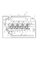
図2に示すように、この画像形成装置1は、電子写真プロセスを用いた4色フルカラーレーザプリンタであり、記録媒体Sにカラー画像形成を行う。画像形成装置1はプロセスカートリッジ方式であり、カートリッジを装置本体2に取り外し可能に装着して、記録媒体Sにカラー画像を形成するものである。ここで、画像形成装置1に関して、開閉ドア3を設けた側を正面(前面)、正面と反対側の面を背面(後面)とする。また、画像形成装置1を正面から見て右側を駆動側、左側を非駆動側と称す。
As shown in FIG. 2, the image forming apparatus 1 is a four-color full-color laser printer using an electrophotographic process, and forms a color image on a recording medium S. The image forming apparatus 1 is a process cartridge type, and a cartridge is detachably attached to the apparatus
装置本体2には第1のカートリッジPY、第2のカートリッジPM、第3のカートリッジPC、第4のカートリッジPKの4つのカートリッジP(PY・PM・PC・PK)が水平方向に配置されている。第1〜第4の各カートリッジP(PY・PM・PC・PK)は、それぞれ同様の電子写真プロセス機構を有しており、現像剤(以下トナーと称す)の色が各々異なるものである。第1〜第4のカートリッジP(PY・PM・PC・PK)には装置本体2の駆動出力部(不図示)から回転駆動力が伝達される。また、第1〜第4の各カートリッジP(PY・PM・PC・PK)には装置本体2からバイアス電圧(帯電バイアス、現像バイアス等)が供給される(不図示)。
In the apparatus
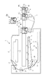
図3に示すように、本実施例の第1〜第4の各カートリッジP(PY・PM・PC・PK)は、電子写真感光体4(以下、感光体ドラムと称す)と、この感光体ドラム4に作用するプロセス手段としての帯電手段及びクリーニング手段を備えた第一枠体を有する。尚、第一枠体をクリーニングユニット8とする。
As shown in FIG. 3, each of the first to fourth cartridges P (PY, PM, PC, PK) of this embodiment includes an electrophotographic photosensitive member 4 (hereinafter referred to as a photosensitive drum) and the photosensitive member. A first frame having a charging unit and a cleaning unit as a process unit that acts on the
また、第1〜第4の各カートリッジP(PY・PM・PC・PK)は、感光体ドラム4上の静電潜像を現像する現像手段を備えた第二枠体である現像装置9を有する。
Each of the first to fourth cartridges P (PY, PM, PC, PK) includes a developing
クリーニングユニット8と現像装置9は互いに結合されている。また、帯電手段としては帯電ローラ5、クリーニング手段としてはクリーニングブレード7、現像手段としては現像剤担持体6(以下、現像ローラと称す)を用いている。カートリッジのより具体的な構成については後述する。
The
第1のカートリッジPYは、現像枠体29内にイエロー(Y)のトナーを収容しており、感光体ドラム4の表面にイエロー色のトナー像を形成する。第2のカートリッジPMは、現像枠体29内にマゼンタ(M)のトナーを収容してあり、感光体ドラム4の表面にマゼンタ色のトナー像を形成する。第3のカートリッジPCは、現像枠体29内にシアン(C)のトナーを収容してあり、感光体ドラム4の表面にシアン色のトナー像を形成する。第4のカートリッジPKは、現像枠体29内にブラック(K)のトナーを収容しており、感光体ドラム4の表面にブラック色のトナー像を形成する。
The first cartridge PY contains yellow (Y) toner in the developing
図2に示すように、第1〜第4のカートリッジP(PY・PM・PC・PK)の上方には、露光手段としてのレーザスキャナユニットLBが設けられている。このレーザスキャナユニットLBは、画像情報に対応してレーザ光Zを出力する。そして、レーザ光Zは、カートリッジPの露光窓部10を通過して感光体ドラム4の表面を走査露光する。
As shown in FIG. 2, a laser scanner unit LB as an exposure unit is provided above the first to fourth cartridges P (PY / PM / PC / PK). The laser scanner unit LB outputs a laser beam Z corresponding to the image information. The laser beam Z passes through the
第1〜第4のカートリッジP(PY・PM・PC・PK)の下方には、転写部材としての中間転写ベルトユニット11を設けている。この中間転写ベルトユニット11は、駆動ローラ13・ターンローラ14・テンションローラ15を有し、可撓性を有する転写ベルト12を掛け渡している。第1〜第4の各カートリッジP(PY・PM・PC・PK)の感光体ドラム4は、その下面が転写ベルト12の上面に接している。その接触部が1次転写部である。転写ベルト12の内側には、感光体ドラム4に対向させて1次転写ローラ16を設けている。
Below the first to fourth cartridges P (PY, PM, PC, PK), an intermediate
ターンローラ14には転写ベルト12を介して2次転写ローラ17を当接させている。転写ベルト12と2次転写ローラ17の接触部が2次転写部である。中間転写ベルトユニット11の下方には、給送ユニット18を設けている。この給送ユニット18は、記録媒体Sを積載して収容した給紙トレイ19、給紙ローラ20を有する。図2における装置本体2内の左上方には、定着ユニット21と、排出ユニット22を設けている。装置本体2の上面は排出トレイ23としている。記録媒体Sは前記定着ユニット21に設けられた定着手段によりトナー像が定着され、前記排出トレイ23へ排出される。
A
≪画像形成動作≫
フルカラー画像を形成するための動作は次のとおりである。
≪Image formation operation≫
The operation for forming a full-color image is as follows.
第1〜第4の各カートリッジP(PY・PM・PC・PK)の感光体ドラム4が所定の速度で回転駆動される(図3矢印D方向、図2において反時計回り)。
The
転写ベルト12も感光体ドラム4の回転に順方向(図2矢印C方向)に感光体ドラム4の速度に対応した速度で回転駆動される。レーザスキャナユニットLBも駆動される。レーザスキャナユニットLBの駆動に同期し、各カートリッジPにおいて、帯電ローラ5が感光体ドラム4の表面を所定の極性、電位に帯電する。そして、信号に応じて感光体ドラム4の表面をレーザ光Zで走査露光する。これにより、各感光体ドラム4の表面に対応色の画像信号に応じた静電潜像が形成される。形成された静電潜像は、所定の速度で回転駆動(図3矢印E方向、図2において時計回り)される現像ローラ6により現像される。
The
前記のような電子写真画像形成プロセス動作により、第1のカートリッジPYの感光体ドラム4にはフルカラー画像のイエロー成分に対応するイエロー色のトナー像が形成される。そして、そのトナー像が転写ベルト12上に1次転写される。同様に第2のカートリッジPMの感光体ドラム4にはフルカラー画像のマゼンタ成分に対応するマゼンタ色トナー像が形成される。そして、そのトナー像が、転写ベルト12上にすでに転写されているイエロー色のトナー像に重畳されて1次転写される。同様に第3のカートリッジPCの感光体ドラム4にはフルカラー画像のシアン成分に対応するシアン色トナー像が形成される。そして、そのトナー像が、転写ベルト12上にすでに転写されているイエロー色、マゼンタ色のトナー像に重畳されて1次転写される。同様に第4のカートリッジPKの感光体ドラム4にはフルカラー画像のブラック成分に対応するブラック色トナー像が形成される。そして、そのトナー像が、転写ベルト12上にすでに転写されているイエロー色、マゼンタ色、シアン色のトナー像に重畳されて1次転写される。このようにして、転写ベルト12上にイエロー色、マゼンタ色、シアン色、ブラック色の4色フルカラーの未定着トナー像が形成される。
By the electrophotographic image forming process operation as described above, a yellow toner image corresponding to the yellow component of the full color image is formed on the
一方、所定の制御タイミングで記録媒体Sが1枚ずつ分離されて給送される。その記録媒体Sは、所定の制御タイミングで2次転写ローラ17と転写ベルト12との当接部である2次転写部に導入される。これにより、記録媒体Sが前記2次転写部へ搬送されていく過程で、転写ベルト12上の4色重畳のトナー像が記録媒体Sの面に順次に一括転写される。
On the other hand, the recording medium S is separated and fed one by one at a predetermined control timing. The recording medium S is introduced into a secondary transfer portion that is a contact portion between the
≪カートリッジの構成≫
図4(a)、(b)は、本実施例に関わるカートリッジP(PY・PM・PC・PK)を、それぞれ別の角度から見た斜視図である。ここから先の説明において、カートリッジP(PY・PM・PC・PK)は、各色同様な構成をとるため、表記をカートリッジPとする。
≪Configuration of cartridge≫
FIGS. 4A and 4B are perspective views of the cartridge P (PY / PM / PC / PK) according to the present embodiment as seen from different angles. In the following description, since the cartridge P (PY, PM, PC, PK) has the same configuration as each color, the notation is referred to as the cartridge P.
カートリッジPは、感光体ドラム4の回転軸線aの方向を長手方向(X方向)とする横長の略直方体形状であり、クリーニングユニット8と、現像装置9と、駆動側カバー部材24、非駆動側カバー部材25を有する。
The cartridge P has a laterally substantially rectangular parallelepiped shape in which the direction of the rotation axis a of the
図4(a)は、カートリッジPを駆動側から見た斜視図である。また、図4(b)は、カートリッジPを非駆動側から見た斜視図である。カートリッジPは、クリーニングユニット8に固定された駆動側カバー部材24と非駆動側カバー部材25が、現像装置9の揺動中心(図4(a)中一点鎖線a)を中心として回転可能に支持した二枠体構成となっている。なお詳細は後述するが、現像装置9はバネ(不図示)等で一定方向(図3矢印W1方向)に付勢されている。
FIG. 4A is a perspective view of the cartridge P viewed from the drive side. FIG. 4B is a perspective view of the cartridge P viewed from the non-driving side. The cartridge P is supported by a drive-
図3に示すように、クリーニングユニット(ドラムユニット)8は、感光体ドラム4と、帯電ローラ5と、クリーニングブレード7を有するクリーニング容器26、把持部45により構成される。図4(a)、(b)に示すように、感光体ドラム4は、駆動側カバー部材24、非駆動側カバー部材25によって回転可能に支持されており、ドラム駆動カップリング4aから装置本体2のモータ(不図示)の駆動力を得て回転駆動する(図3矢印D方向)。図3に示すように、帯電ローラ5は、クリーニング容器26の帯電ローラ軸受27によって両端部を回転可能に支持されており、感光体ドラム4の表面に接触して従動回転し、帯電バイアスの供給を受けて感光体ドラム4の表面を帯電させる。このとき、表面を均一に帯電させるため、帯電ローラ5の両端部は帯電ローラ加圧バネ28によって感光体ドラム4の表面に加圧されている。クリーニングブレード7は、クリーニング容器26に固定されており、先端の弾性ゴム部を感光体ドラム4の回転方向(図3矢印D方向)に対してカウンター方向に当接させて設けている。画像形成時には、感光体ドラム4上に残留した転写残トナーを掻き取って感光体ドラム4の表面をクリーニングする。このとき、転写残トナーを完全に掻き取るためにクリーニングブレード7の先端は、感光体ドラム4の表面に対して所定の圧をもって当接している。また、クリーニングブレード7によって感光体ドラム4の表面から掻き取られた転写残トナーは、廃トナーとしてクリーニング容器26の廃トナー収容部26aに収容される。そのためクリーニング容器26には、感光体ドラム4やクリーニングブレード7との隙間からの廃トナーの漏れ出しを防止するための廃トナー回収シート部材70を感光ドラム4の長手方向に固定している。また、クリーニングブレード7の長手方向両端部にクリーニングブレード端部シール部材(不図示)が設けられている。
As shown in FIG. 3, the cleaning unit (drum unit) 8 includes a
把持部45は、ユーザがカートリッジPを把持するための箇所であり、クリーニング容器26に一体、もしくは、別部品として取り付けられている。ただし、画像形成装置1の構成によっては、後述する装置本体2へのカートリッジPの着脱姿勢が本実施例と異なる場合がある。その場合、把持部45は、現像枠体29にあってもよい。
The
本実施例では、カートリッジPは、略直方体である。6面体のうち一面58は、先に述べた感光体ドラム4上のトナー像を中間転写ベルトユニット11に転写するための露出部4bを有している。また、一面58に対向する面59は、上述した把持部45を有している。
In the present embodiment, the cartridge P is a substantially rectangular parallelepiped. One
また、図4(a)、(b)に示すように、カートリッジPは、後述する梱包部材46に梱包された際、梱包部材46内での位置が規制される部位として、以下を有する。即ち、被第一規制部24b、25b、24g、25gは、梱包部材46に対して鉛直下方向(Z2方向)と水平方向(Y1、Y2方向)の位置規制がされる。また、被第二規制部26cは、梱包部材46に対して鉛直上方向(Z1方向)への移動が規制される。さらに、被第三規制部24f、25fは、カートリッジPの長手方向(感光体ドラム4の軸線方向、X1、X2方向)の移動が規制される。尚、上記の各被規制部を用いたカートリッジPの梱包部材46内での位置規制に関しては、後に詳細に説明する。
Further, as shown in FIGS. 4A and 4B, the cartridge P has the following as a portion whose position in the packing
≪カートリッジの着脱構成≫
次に、カートリッジPの装置本体2への着脱動作について説明する。
≪Removal configuration of cartridge≫
Next, the attaching / detaching operation of the cartridge P to the apparatus
図5はカートリッジトレイ43が装置本体2から引き出され、カートリッジPが着脱可能な状態を示した概略断面図である。図6はカートリッジPのカートリッジトレイ43への着脱動作を示した概略断面図である。図5に示すように、装置本体2内にはカートリッジPを装着可能なカートリッジトレイ43が設けられている。カートリッジトレイ43は装置本体2に対して実質的に水平方向であるG1、G2方向に直線移動(引き出し、押し込み)可能に構成されている。そして、カートリッジトレイ43は、装置本体2内の装着位置と、装着位置から引き出された引き出し位置とをとりうる。
FIG. 5 is a schematic cross-sectional view showing a state in which the
まず、カートリッジPの装置本体2への装着動作について説明する。
First, the mounting operation of the cartridge P to the apparatus
開閉ドア3を開け、カートリッジトレイ43を図5中矢印G1方向に移動させることで、カートリッジトレイ43は引き出し位置に移動する。この状態において、カートリッジPは図6中矢印H1方向からカートリッジトレイ43に装着され、保持される。カートリッジPを保持したカートリッジトレイ43を図5中矢印G2方向に移動させ、カートリッジトレイ43は装置本体2内の装着位置に移動する。そして、開閉ドア3を閉めることで、カートリッジPの装置本体2への装着動作が完了する。
By opening the opening /
次に、カートリッジPの装置本体2からの取り出しについて説明する。前述したカートリッジPの装置本体2への装着動作と同様にして、カートリッジトレイ43を引き出し位置に移動させる。この状態において、カートリッジPが図6中矢印H2方向に取り出され、カートリッジPの装置本体2からの取り出し動作が完了する。以上の動作により、カートリッジPは装置本体2に着脱可能となっている。尚、梱包部材46から装置本体2にカートリッジPを装着する過程は、後に詳細に説明する。
Next, the removal of the cartridge P from the apparatus
≪現像装置の構成≫
図3、図7に示すように、現像装置9は現像手段としての現像ローラ6の回転軸方向を長手方向に延びた横長の形状である。現像ローラ6の他に、現像枠体29、現像ブレード31、現像剤供給ローラ33、現像端部シール部材34R・34L、可撓性シート部材35、供給ローラ軸シール37R・37Lによって構成される(図7)。また、図3に示すように、現像枠体29は、トナーを収容するためのトナー収容室29cを備え、トナー収容室29cからトナーを排出するための開口部29bを有している。現像ローラ6および現像剤供給ローラ33は現像枠体29の開口部29bに配置されている。そして、図7に示すように、前記現像ローラ6の軸両端部(芯材6a)は、それぞれ現像枠体29の両側面に取り付けられた駆動側軸受38、非駆動側軸受39によって回転自在に支持されている。また、現像ローラ6の芯材6aと現像剤供給ローラ33の芯材33aの駆動側端部には、それぞれ現像ローラギア40と供給ローラギア41が配置され、現像駆動入力ギア42と噛み合っている。現像駆動入力ギア42は、現像駆動カップリング42aを備えており、装置本体2側の駆動出力カップリング(不図示)が係合して装置本体2の駆動モータ(不図示)の駆動力の伝達がなされ、現像ローラ6と現像剤供給ローラ33が所定の速度で回転駆動される。現像ブレード31は、厚み0.1mm程度の弾性を有する金属薄板であり、現像ブレード31の短手方向の自由端は現像ローラ6の回転方向(図3における矢印E方向)に対してカウンター方向に当接している。
≪Developer configuration≫
As shown in FIGS. 3 and 7, the developing
図7に示すように、現像端部シール部材34R・34Lは現像枠体29の開口部の両端に配置され、現像ブレード31および現像ローラ6と、第二枠体である現像枠体29との隙間からのトナー漏れを防止している。また、可撓性シート部材35は、現像枠体29の開口部における現像ブレード31と対向する側に、長手方向に沿って、現像ローラ6と当接するように配置され、現像枠体29と現像ローラ6との隙間からのトナー漏れを防止している。また、供給ローラ軸シール37R・37Lは、現像剤供給ローラ33の芯材33aにおける現像枠体29の外側に露出した部分に装着されており、現像枠体29に設けられた芯材通し穴29dと芯材33aの隙間からのトナー漏れを防止している。
As shown in FIG. 7, the developing
現像装置(現像ユニット)9は、図4に示した揺動中心(軸線a)を中心に現像ローラ6が感光体ドラム4に接触する方向(図3矢印W1方向)に加圧バネ(不図示)によって常に付勢されており、現像ローラ6が感光体ドラム4に当接している。画像形成時には、駆動により現像剤供給ローラ33と現像ローラ6が回転して摺擦することで現像枠体29内のトナーが現像ローラ6上に担持される。現像ブレード31は、現像ローラ6の周面に形成されるトナー層の厚みを規制すると共に、当接圧により現像ローラ6との間で摩擦帯電による電荷をトナーに付与する。そして現像ローラ6と感光体ドラム4の接触部で現像ローラ6上の電荷を帯びたトナーが感光体ドラム4上の静電潜像に付着し、潜像が現像されている。
また、非像形成時には、現像ローラ6が感光体ドラム4から離間して、現像ローラ6の表面が変形するのを防いでいる。即ち、現像装置9は、クリーニングユニット8に対して移動可能で現像ローラ6を感光体ドラム4に対して接離させることが可能な構成になっている。
The developing device (developing unit) 9 has a pressure spring (not shown) in a direction (in the direction of arrow W1 in FIG. 3) in which the developing
Further, at the time of non-image formation, the developing
≪梱包部材の構成≫
梱包部材46の構成について図1、図8、図9、図10を用いて説明する。
≪Package material composition≫
The configuration of the packing
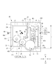
図1は、本実施例のカートリッジPと梱包部材46の梱包状態を示す概略断面図である。図8(a)、(b)は、本実施例の梱包部材46のカートリッジPを取り出し可能な状態を示す梱包部材46の概略斜視図であり、それぞれ別の角度から見た斜視図である。図9(a)、(b)は、本実施例のカートリッジPの梱包部材46から取り出し可能な状態を示す概略斜視図であり、それぞれ別の角度から見た斜視図である。ここで、梱包部材46の長手方向は、梱包部材46にカートリッジPを収納した時のカートリッジPの長手方向(図中X1、X2方向)と同一方向である。図10は、本実施例の梱包部材46のカートリッジ梱包状態を示す概略斜視図である。
図8(a)、(b)に示すように、梱包部材46は、枠体部47と蓋部48、ヒンジ部49から構成される。枠体部47と蓋部48は、枠体部47と蓋部48と一体成形されたヒンジ部49の回転軸49aを回転中心として、互いに回転自在となっている(図1)。梱包部材46を構成する枠体部47、蓋部48、ヒンジ部49は、薄肉のプラスチックフィルム、例えばポリエチレンテレフタレート、ポリプロピレン等の樹脂から構成され、真空成型、プレス、射出成型によって成形することが可能である。但し、真空成型で形成することで、低コストで加工可能である。図8に示すように、枠体部47は第一開口47c1を有する凹形状である第一凹部47cを有する。また、蓋部48は第二開口48b1を有する凹形状である第二凹部48bを有する。また、枠体部47、蓋部48には、第一凹部47c、第二凹部48bの外周を囲うようにしてフランジ部47a、48aが形成されている。そして、枠体部47と蓋部48は、ヒンジ部49で連結され、一体成形されている。そして、蓋部48は、枠体部47の第一開口47c1を覆う閉じ位置(図1、図11)と、第一開口47c1を開放する開放位置(図12)とをとることができる。
FIG. 1 is a schematic cross-sectional view showing a packing state of the cartridge P and the packing
As shown in FIGS. 8A and 8B, the packing
梱包部材46へのカートリッジPの装着について説明する。カートリッジPは、梱包部材46の枠体部47に、図9(a)、(b)に示すように、第一の状態で支持される。支持の詳細について後述する。ここで、第一の状態とは、図9(a)、(b)に示すように、第一開口47c1からZ2方向に進入したカートリッジPが枠体部47から取り出し可能に装着されている。そして、カートリッジPが枠体部47によって保持された状態であり、枠体部47がカートリッジPの感光体ドラム4の露出部4b(図4(b)参照)を覆っている状態である。また、この第一の状態では、感光体ドラム4の露出部4bが枠体部47の内面に接触することがなく、かつ、ユーザがカートリッジPの把持部45を把持可能な姿勢である。そして、図9(a)、(b)に示す状態から、枠体部47に対して蓋部48をヒンジ部49の回転軸49aで回転させ、図10に示すように、枠体部47のフランジ部47aと蓋部48のフランジ部48aを合わせる。その後、枠体部47のフランジ部47aと蓋部のフランジ部48aを、全面または一部で接合する。これにより、図1に示すように、枠体部47の第一凹部47cと蓋部48の第二凹部48bが一緒になって、接合部46a(図1、図10)を形成する。そして、内部に収納空間46bを作り、その収納空間46bにカートリッジPを内包することが可能となる 第二の状態(梱包状態)となる(図10)。この状態において、蓋部48の第二凹部48bは、略直方体であるカートリッジPの把持部45と収納するようにカートリッジPの全体、または、一部を覆っている。尚、接合部46aは、ヒンジ部49と対向する位置に開封部46a1を有している。詳細は後述するが、ユーザは接合部46aの開封部46a1から梱包部材46を開封することになる。また、開封部46a1が接合されていない場合も当然ありうる。 以上の梱包により、カートリッジP全体が枠体部47と蓋部48で覆われ、梱包状態となる(図1、図10参照)。尚、図1では、カートリッジPに対する枠体部47のフランジ部47aと蓋部48のフランジ部48aの接合部46aは、カートリッジPを長手方向から見て、カートリッジPの高さcの略半分の位置に形成されているが、その限りではない。例えば、接合部がカートリッジPの高さcよりも上であっても良い。また、カートリッジPは略直方体として、梱包部材46は相似形状としたが、カートリッジPはどのような形でも良く、カートリッジPの全体もしくは、保護すべき一部が包まれていれば梱包部材46もどのような形状でも構わない。また、枠体部47のフランジ部47aと蓋部48のフランジ部48aとの接合手段としては、熱溶着、接着剤、両面テープ、引っ掛け等が挙げられる。しかし、フランジ部47aと蓋部48のフランジ部48aの接合が可能であれば良く、これらの手段に限定されるものでは無い。即ち、枠体部47と蓋部48とは別体で、フランジ部47aとフランジ部48aとが接合する構成でも良い。
The mounting of the cartridge P on the packing
次に、梱包状態における、梱包部材46によるカートリッジPの位置規制について説明する。カートリッジPのX1、X2方向の位置規制を行うため、梱包部材46は図8(a)、(b)に示す枠体部47の内面の長手方向両端に形成された一対の第三規制部47fを、図9(a)、(b)に示すカートリッジPの被第三規制部24f、25fに接触させる。従って、カートリッジPのX1、X2方向の位置は、先に説明した、第一の状態で規制される。また、図4(a)、図4(b)に示すカートリッジPのY1、Y2方向及びZ2方向の位置規制を行うため、梱包部材46は、図8(a)、図8(b)に示す枠体部47の内面に形成された第一規規制部47g、47bを有する。ここで、Z2方向は、カートリッジPの枠体部47に対する進入方向である。また、Y1、Y2方向は、カートリッジPの長手方向と交差する方向(直交する方向)かつカートリッジPが枠体部47に進入する進入方向Z2と交差する方向(直交する方向)である。
Next, the position restriction of the cartridge P by the packing
そして、図9(a)、(b)に示す、カートリッジPの被第一規制部24g、25g、24b、25bに接触させる。従って、カートリッジPのY方向の位置は、先に説明した、第一の状態で規制される。また、図8(a)、図8(b)に示すように、蓋部48には第二規制部48cが形成されている。図9(a)、図9(b)に示すように、第二規制部48cは、梱包部材46の梱包状態(第二の状態)において、カートリッジPの被第二規制部26cと相対する位置に形成されている。そして、カートリッジPは、梱包状態(第二の状態)において、被第二規制部26cが蓋部48の第二規制部48cと接触する。これにより、カートリッジPが第一規規制部47bから離間する方向であるZ1方向への移動を規制することによって、カートリッジPの位置規制がなされる。つまり、図9(a)、図9(b)に示す、第一の状態ではカートリッジPが重力方向とは反対のZ1方向には規制されていない状態である。上述した梱包状態(第二の状態)において、梱包部材46は、図8に示す、規制部47f、47b、48c、47g以外のところでは、カートリッジPに接していない。そのため、梱包部材46は、運搬時の振動や衝撃が発生したとき、各規制部以外の部分で弾性変形や塑性変形が発生し、運搬時の振動や衝撃を吸収することができる。故に、梱包部材46は、運搬時の振動や衝撃を感光体ドラム4及びプロセス手段に直接伝えず、カートリッジPを保護する保護部材として機能する。したがって、感光体ドラム4を保護するドラムシャッタをカートリッジPから無くすことも可能になってくる。また、梱包部材46の各規制部は、カートリッジPの感光体ドラム4の潜像を形成する領域を除く部位であれば、カートリッジPのどの位置で当接しても良い。例えば、現像枠体29に当接させても同様の効果を得ることができる。但し、被第三規制部24b、25bの剛性は高く形成されている方が、運搬時の衝撃等でカートリッジPが破損することが少なくなる。また、第一の状態において、既にカートリッジPは梱包部材46の枠体部47に、X1、X2方向と、Y1、Y2方向と、Z2方向を規制されている。つまり、梱包部材46にカートリッジPを固定するため、第一の状態から第二の状態に至る際に、蓋部48を被せるだけで良く、より組立性を向上させることができる。また、規制部47f、47b、48c、47gは、梱包部材46に形成されているとしたが、別部材で構成されていても良い。
And it is made to contact with the to-
先に説明したように、図4(a)に示すように、現像装置9は、前述したようにクリーニングユニット8に固定された駆動側カバー部材24と非駆動側カバー部材25に回転可能に支持されている。そのため、図11(b)で示すように、現像装置9は、カートリッジPの運搬時に発生する振動や衝撃により、付勢力に逆らって時計回り方向(図中矢印W2方向)に回動する可能性がある。このとき、現像装置9は、付勢力によって付勢された姿勢に復帰する回動運動が発生し、クリーニングユニット8に対して衝突してしまい、感光体ドラム4と現像ローラ6の摺擦メモリが画像不良となる可能性がある。また、上述においては、現像装置9がバネ等の付勢手段を有する場合に関して述べたが、付勢手段を有しない構成においても、カートリッジP運搬時において、同様の衝突が発生する可能性がある。ここで、カートリッジPの運搬時における、梱包部材46内での現像装置9がクリーニングユニット8に対して移動しづらい固定方法について、説明する。 図11は、カートリッジPと梱包部材46の梱包状態を示す概略断面図である。図11(a)は、現像装置9がクリーニング枠体8に対してバネ(不図示)等で時計回り方向(図中矢印W1方向)に付勢された状態で、現像ローラ6が感光体ドラム4に当接した状態を示している。それに対して図11(b)は、現像装置9がクリーニング枠体8に対して、付勢力に逆らって時計回り方向(図中矢印W2方向)に回動した状態を示している。
As described above, as shown in FIG. 4A, the developing
現像装置9は、被第四規制部29dを有している。また、梱包部材46の蓋部48には第四規制部48dを形成している。つまり、図11(b)に示すように、回転軸線a(図4(a)参照)を中心とした、時計回り方向(図中矢印w1方向)において、現像装置9の被第四規制部29dの下流側に第四規制部48dを配置する。そこで、梱包部材46は、カートリッジPを梱包した際、第四規制部48dで現像装置9の被第四規制部29dを支持し、現像装置9の時計回り方向(図11(b)矢印W2方向)への過度の回動を抑えることができる。以上説明したように、現像装置9に被第四規制部29dを設け、また、梱包部材46の蓋部48に第四規制部48dを形成することで、現像装置9の時計回り方向(図11(b)矢印W2方向)の過度の回動を抑えることができる。これにより、カートリッジPを運搬時に発生する振動や衝撃による現像装置9とクリーニングユニット8の衝突を低減することが可能である。これにより、例えば、現像ローラ6と感光体ドラム4との摺擦による感光体ドラム上のメモリを低減することが可能である。
The developing
≪把持部と梱包部材の関係≫
カートリッジPの把持部45と梱包部材46の位置関係について、図11を用いて説明する。カートリッジPは、クリーニングユニット8に把持部45を設けており、Y1方向において、クリーニングユニット8、現像装置9、ヒンジ部49の順になる姿勢で梱包される。ただし、前述したように、把持部45は、現像装置9に設けられることもある。その場合、カートリッジPは、Y1方向において、ヒンジ部49、クリーニングユニット8、現像装置9の順になる姿勢で梱包される。
≪Relationship between gripping part and packing material≫
The positional relationship between the gripping
梱包部材46からのカートリッジP取り出し動作について、図10、図12を用いて説明する。図12は、梱包部材46からカートリッジPを取り出し可能な状態を示した概略断面図である。尚、カートリッジPの取り出し動作は、蓋部46の開封、把持部45の把持、カートリッジPの取り出しから装置本体2への装着の順で行われる。
The operation of taking out the cartridge P from the packing
図10において、ユーザは、枠体部47と開放可能に結合した蓋部46を、不図示の手段により開封部46a1から接合部46aを分離する。すなわち、フランジ部47aとフランジ部48aに分ける。そして、ユーザは、蓋部48をヒンジ部49の回転軸49aを軸として、図12矢印R方向へ回動させる。蓋部48が概ね180度回動することでカートリッジPが取り出し可能な状態になり(図12)、蓋部48の開封動作は、完了する。尚、カートリッジPが取り出し可能であれば、蓋部48は、180度回動していなくても良い。ここで、ユーザは、梱包部材46を開封する際、ヒンジ部49を手前側にするよりも、開封部46a1を手前側にする方が、梱包部材46の開封作業を行う操作が容易である。故に、今後の説明は、ユーザが梱包部材46の開封部46a1を手前側にした状態で開封したこととする。
In FIG. 10, the user separates the
次に、ユーザは把持部45を把持する。把持部45の把持は、ユーザが蓋部48を回動後、把持部45を把持することで行われる。このとき、前述したように把持部45は、開封部46a1側に位置している。そのため、ユーザは、蓋部48を開封した際、把持部45を認識しやすく、また、蓋部48に把持動作を阻害されず、把持部45の把持をスムーズに行えることになる。
Next, the user grips the
次に、カートリッジPの取り出しから装置本体2への装着動作について説明する。この動作は、ユーザが図12で示す矢印J方向にカートリッジPを移動させ取り出し、装置本体2へカートリッジを装着することで行われる。ところで、ユーザは装置本体2へカートリッジPを装着する際、図5で示すカートリッジトレイ43の引き出し方向G1に対して、装置本体2よりも下流側に位置して、操作することとなる。また、ユーザがカートリッジPを装置本体2へ装着するときのカートリッジPの姿勢は、引き出し方向G1において、クリーニングユニット8が現像装置9よりも下流側になった姿勢である。また、図6に示す、カートリッジPの装着方向H1において、下流側に感光ドラム4があり上流側に把持部45となる姿勢である。この姿勢は、ユーザが梱包部材46にあるカートリッジPの把持部45を把持するときのカートリッジPの姿勢と同じである。つまり、ユーザは、梱包部材46からカートリッジPを取り出したそのままの姿勢でカートリッジPを装置本体2に装着することができる。よって、ユーザは、梱包部材46からカートリッジPを取り出し装置本体2に装着する間、カートリッジPの持ち替えや手首のひねりといった煩わしさがなく、ユーザビリティ向上につながることになる。
Next, the operation of removing the cartridge P and mounting it on the apparatus
以上説明したように、本実施例は、梱包部材46は、運搬時の振動や衝撃が発生したとき、各規制部以外の部分で弾性変形や塑性変形が発生し、運搬時の振動や衝撃を吸収することができる。梱包部材46は、カートリッジPを運搬時の振動や衝撃から保護することができるカートリッジPの梱包部材46として機能する。
As described above, according to the present embodiment, the packing
また、カートリッジPが感光体ドラム4を回転可能に支持するクリーニング枠体である第一枠体8と、第一枠体8に回転可能に支持されプロセス手段を支持する現像枠体である第二枠体9で構成される。そして、梱包部材46は、第二枠体9の収納空間46b内での移動を規制する第四規制部48dを有する。これにより、カートリッジPは、プロセス手段が感光体ドラム4から離れる方向への第二枠体9の回転が規制され、運搬時の振動や衝撃を抑制される。
The cartridge P is a
また、カートリッジPが感光体ドラム4との対向部に梱包部材46からカートリッジPを取り出すための把持する把持部45を有する。このとき、感光体ドラム4の軸線方向と直交する断面において、枠体部47側に感光体ドラム4を、蓋部48側に把持部45を配置している。これにより、ユーザは、梱包部材46からのカートリッジP開梱時に、ユーザビリティ性を損なうことなく梱包部材46からカートリッジPを取り出すことが可能になる。
In addition, the cartridge P has a
尚、本実施例において、カートリッジPを略直方体とし、感光ドラム4の露出部と対向する面に把持部45を有する構成としたが、それに限定されるものではない。カートリッジPが梱包部材46に梱包される際、枠体部47の第一凹部47cに露出部4bが収容され、蓋部48の第二凹部48bに把持部45が収容されるような構成とすれば本発明を適用可能である。例えば、カートリッジを略三角柱とし、三角面以外の一面に露出部を有するとする。このとき、把持部は露出部に対向しない面に配置されることになる。この場合においても、カートリッジが梱包部材に梱包されたとき、枠体部の凹部に露出部が収容され、蓋部の凹部に把持部が収容される構成をとれば、本発明を適用可能となる。
In the present embodiment, the cartridge P has a substantially rectangular parallelepiped shape and the
以上説明したように、本実施例は、カートリッジPを梱包する梱包部材46、及び、梱包部材46に梱包されたカートリッジPに関するものである。ここでのカートリッジPとは、把持部45を有した第一枠体であるクリーニングユニット8と第二枠体である現像装置9で構成されたものである。ここでの梱包部材46とは、互いに回転可能に支持する回転軸であるヒンジ部49で連結された枠体部47と蓋部48から構成されたものである。また、枠体部47には、第一凹部47cを、蓋部48には、第二凹部48bをそれぞれ有している。そして、梱包部材46は、ヒンジ部49を回転中心として回動し、第一凹部47cと第二凹部48bでカートリッジPを収容する空間である収容空間46bを形成する。カートリッジPは、梱包部材46の収容空間46bに梱包されたときに以下のように規制部47g、47bで位置規制される。即ち、感光体ドラム4の軸線方向X1,X2と直交する方向、かつ、カートリッジPが枠体部47に進入する進入方向Z2と交差する方向において、ヒンジ部49、現像装置9、クリーニングユニット8の順になる状態である。これにより、ユーザは、開封部46a1を手前側に梱包部材46を開梱した際、クリーニングユニット8にある把持部45がユーザに近い位置にあるので、把持部45を認識しやすい。また、蓋部48が把持動作を妨げないので、ユーザは把持部45を把持しやすい。そのため、ユーザは、梱包部材46からカートリッジPの取り出しをスムーズに行うことが可能となる。そして、ユーザが梱包部材46からカートリッジPを取り出すときのカートリッジPの姿勢と、装置本体2へのカートリッジPを装着する姿勢が概ね一致することになる。そのため、カートリッジPを梱包部材46から取り出して装置本体2へ装着する間、ユーザは、カートリッジPの持ち替えや手首のひねり等の動作を極力減らすことが可能になる。そのため、本実施例によってユーザビリティ性は大きく向上することとなる。
As described above, the present embodiment relates to the packing
(実施例2)
次に、実施例2として、図13〜図15を用いて説明する。実施例2は、実施例1の実施形態であったクリーニングユニット8と現像装置9で構成された、カートリッジPに対し、現像装置のみで構成されたカートリッジQ(QY、QM、QC、QK)としている。そのため、実施例1と説明が重複する箇所に関しては、その説明を省略する。
(Example 2)
Next, a second embodiment will be described with reference to FIGS. Example 2 is a cartridge Q (QY, QM, QC, QK) constituted only by the developing device with respect to the cartridge P constituted by the
≪画像形成装置の概略構成≫
まず、本実施例の画像形成装置100の断面概略図を、図14に示す。
<< Schematic configuration of image forming apparatus >>
First, a schematic cross-sectional view of the
この画像形成装置100は、電子写真プロセスを用いた4色フルカラーレーザプリンタであり、記録媒体Sにカラー画像形成を行う。画像形成装置100は、図14に示すように、カートリッジQを装置本体102に取り外し可能に装着可能とし、記録媒体Sにカラー画像を形成するものである。ただし、本実施例おいて、カートリッジQを装置本体102に取り外し可能に装着する構成としているが、その限りではない。クリーニングユニット8が装置本体102に着脱可能な構成をとってもよい。尚、実施例1と同様な機能を持つ装置本体102のその他の部品は、同一符号として、その説明を省略する。
The
≪カートリッジの構成≫
図13(a)、(b)は、本実施例に関わるカートリッジQの斜視図である。図13(a)は、非駆動側から見た斜視図を示している。また、図13(b)は、駆動側から見た斜視図を示している。カートリッジQは、把持部145を有している。把持部145は、ユーザがカートリッジQを把持するための箇所であり、現像枠体129に一体、もしくは、別部品として取り付けられている。また、カートリッジQは、略直方体である。6面体のうち一面158は、現像ローラ6上のトナーを感光体ドラム4に現像するための露出部6bを有している。また、一面158に対向する面159は、上述した把持部145を有している。尚、把持部149の位置については、後述する。
≪Configuration of cartridge≫
FIGS. 13A and 13B are perspective views of the cartridge Q according to the present embodiment. FIG. 13A shows a perspective view seen from the non-driving side. FIG. 13B shows a perspective view seen from the driving side. The cartridge Q has a
カートリッジQには、後述する梱包部材146に梱包された際に、梱包部材146内での位置が規制される部位として、被第三規制部139f、144f、被第一規制部139b、144b、139g、144g、被第二規制部129cを有している。
The cartridge Q has a third
被第三規制部139f、144fは、カートリッジQの現像ローラ6の軸線方向である、長手方向(図中X方向)の後述する梱包部材146内での位置規制に用いられる。被第一規制部139b、144b、129cは、X1、X2方向との直交方向(交差する方向)である水平方向であるY1,Y2と、鉛直下方向であるZ2方向の位置規制に用いられる。 尚、上記の各被規制部を用いたカートリッジQの梱包部材146内での位置規制に関しては、後に詳細に説明する。
The third
その他の構成は、実施例1で説明した現像装置9の構成と同様なため、その説明を省略する。
Since other configurations are the same as the configuration of the developing
≪カートリッジの着脱構成≫
次に、カートリッジQの装置本体102への着脱動作について説明する。
≪Removal configuration of cartridge≫
Next, the attaching / detaching operation of the cartridge Q to the apparatus
図14は、カートリッジトレイ43が装置本体102から引き出され、カートリッジQが着脱可能な状態を示した概略断面図であり、カートリッジQのカートリッジトレイ43への着脱動作を示した概略断面図である。装置本体102内には、カートリッジQを装着可能なカートリッジトレイ43が設けられている。また、カートリッジトレイ43には、あらかじめ、クリーニングユニット8が装着されている。カートリッジトレイ43は、図14に示すように、装置本体102に対して実質的に水平方向であるG1、G2方向に直線移動(引き出し、押し込み)可能に構成されている。そして、カートリッジトレイ43は、装置本体102内の装着位置と、装着位置から引き出された引き出し位置とをとりうる。
FIG. 14 is a schematic cross-sectional view showing a state in which the
まず、カートリッジQの装置本体102への装着動作について説明する。
First, the mounting operation of the cartridge Q to the apparatus
開閉ドア3を開け、カートリッジトレイ43を図14中矢印G1方向に移動させることで、カートリッジトレイ43は引き出し位置に移動する。この状態において、カートリッジQは、図14中矢印H1方向からカートリッジトレイ43に装着され、現像ローラ6の露出部6b(図13参照)が感光体ドラム4の対向部に位置決めされる。次に、カートリッジトレイ43を図14中矢印G2方向に移動させ、カートリッジトレイ43は装置本体102内の装着位置に移動する。そして、開閉ドア3を閉めることで、カートリッジQの装置本体102への装着動作が完了する。
By opening the opening /
一方で、カートリッジQの装置本体102からの取り出しについて説明する。まず、カートリッジトレイ43を図14矢印G1方向に移動させ、引き出し位置に移動させる。この状態において、カートリッジQが図14中矢印H2方向に取り出され、カートリッジQの装置本体102からの取り出し動作が完了する。以上の動作により、カートリッジQは装置本体102に着脱可能となっている。
On the other hand, the removal of the cartridge Q from the apparatus
尚、本実施例では、カートリッジトレイ43にあらかじめクリーニングユニット8が装着されているが、構成はこの限りではなく、装置本体102内にあらかじめクリーニングユニット8が配置されている構成でも良い。また、梱包部材146からカートリッジQを取り出し、装置本体102に装着するまでの過程は、後述する。
In this embodiment, the
≪梱包部材の構成≫
梱包部材146の構成について図15を用いて説明する。
≪Package material composition≫
The configuration of the packing
尚、実施例1の梱包部材46の構成と同様な点に関しては、その説明を省略する。
In addition, about the point similar to the structure of the
図15は、本発明に係る梱包部材146のカートリッジQの梱包状態を示す概略断面図である。梱包部材146は、枠体部147と蓋部148、ヒンジ部149から構成される。枠体部147と蓋部148は、ヒンジ部149の回転軸149aを回転中心として、互いに回転自在となっている。梱包部材146を構成する枠体部147、蓋部148、ヒンジ部149は、薄肉のプラスチックフィルム、例えばポリエチレンテレフタレート、ポリプロピレン等の樹脂から構成され、例えば真空成型、プレス、射出成型によって成型することが可能である。但し、実施例1と同様、真空成型で形成することで、低コストで加工可能である。
FIG. 15 is a schematic sectional view showing a packing state of the cartridge Q of the packing
また、梱包部材146は、梱包部材146を開封するための接合部146aを有する。接合部146aは、梱包部材146が梱包状態において、ヒンジ部149と対向する位置にある。枠体部147は第一開口147c1を有する凹形状である第一凹部147cを有する。また、蓋部148は第二開口148b1を有する凹形状である第二凹部148bを有する。また、枠体部147、蓋部148には、第一凹部147c、第二凹部148bの外周を囲うようにしてフランジ部147a、148aが形成されている。そして、枠体部147と蓋部148は、ヒンジ部149で連結され、一体成形されている。そして、蓋部148は、枠体部147の第一開口47c1を覆う閉じ位置(図1、図11)と、第一開口147c1を開放する開放位置とをとることができる。
Further, the packing
次に、梱包部材146へのカートリッジQの固定について説明する。
Next, fixing of the cartridge Q to the packing
カートリッジQは、梱包部材146の枠体部147に第一の状態で支持される。支持の詳細について後述する。第一の状態とは、第一開口147c1から進入したカートリッジQが枠体部147から取り出し可能に装着されている。で、そして、カートリッジQが枠体部147によって保持された状態であり、枠体部147がカートリッジQの現像ローラ6の露出部6bを覆っている状態である。また、この第一の状態では、現像ローラ6の露出部6bが枠体部147の内面に接することがなく、枠体部147に対して蓋部148をヒンジ部149の回転軸149aで回転させ開梱した状態で、ユーザがカートリッジQの把持部145を把持可能な姿勢である。
The cartridge Q is supported in the first state by the
上記の開梱状態(不図示)から、枠体部147に対して蓋部148をヒンジ部149の回転軸149aで回転させ、図15に示すように、枠体部147のフランジ部147aと蓋部148のフランジ部148aを合わせる。その後、相対した枠体部147のフランジ部147aと、蓋部のフランジ部148aを、全面または一部で接合する。これにより、図15に示すように、枠体部147の第一凹部147cと蓋部148の第二凹部148bが一緒になって、接合部146aを形成し、内部に収納空間146bを作り、その収納空間146bにカートリッジQを内包することが可能となる。この状態において、蓋部148の第二凹部148bは、略直方体であるカートリッジQの把持部145と収納するようにカートリッジQの全体、または、一部を覆っている。以上の梱包により、カートリッジQ全体が枠体部147と蓋部148で覆われ、梱包状態(第二の状態)となる(図15)。
From the unpacking state (not shown), the
次に、梱包状態における、梱包部材146によるカートリッジQの位置規制について説明する。カートリッジQのX方向の位置の規制を行うため、梱包部材146は、枠体部147の内面に形成された一対の第三規制部(不図示)を、図13(a)、(b)に示すカートリッジQの被第三規制部139fと被第三規制部144fに接触させる。従って、カートリッジQのX1、X2方向の位置は、先に説明した、第一の状態で規制される。また、図15に示すカートリッジQのY1、Y2方向、及びZ2方向への位置規制を行う。そのため、梱包部材146は、枠体部147の内面に形成された第一規制部147g、147bを、図13(a)、(b)に示すカートリッジQの被第一規制部144g、144bに接触させる。従って、カートリッジQのY1、Y2方向、及びZ2方向の位置は、先に説明した、第一の状態で規制される。
Next, the position restriction of the cartridge Q by the packing
また、図15に示すように、蓋部148には第二規制部148cが形成されている。第二規制部148cは、梱包部材146の梱包状態(第二の状態)において、カートリッジQの被第二規制部129cと対応する位置に形成されている。そして、カートリッジQは、梱包状態(第二の状態)において、被第二規制部129cが蓋部148の第二規制部148cと接触する。これにより、カートリッジQは、Z1方向の位置規制がなされる。つまり、第一の状態ではカートリッジQが重力方向と反対のZ1方向には規制されていない状態である。
Further, as shown in FIG. 15, the
上述した梱包状態(第二の状態)において、梱包部材146は、図15に示す、規制部144f、147b、148c、147gの以外のところでは、カートリッジQに接していない。そのため、梱包部材146は、実施例1と同様に、運搬時の振動や衝撃が発生したとき、各規制部以外の部分で弾性変形や塑性変形が発生し、運搬時の振動や衝撃を吸収することができる。故に、梱包部材146は、運搬時の振動や衝撃を現像ローラ6及びその他のプロセス手段に直接伝えず、カートリッジQを保護する保護部材として機能する。
In the packing state (second state) described above, the packing
また、梱包部材146の各規制部は、カートリッジQの現像ローラ6の現像を形成する領域を除く部位であれば、カートリッジQのどの位置で当接しても良い。但し、被第三規制部139b、144bの剛性は高く形成されている方が、これにより運搬時の衝撃等でカートリッジQが破損することが少なくなる。また、第一の状態において、既にカートリッジQは梱包部材146の枠体部147に、長手方向と、Y1、Y2方向と、Z2方向を規制されている。つまり、梱包部材146にカートリッジQを固定するため、第一の状態から第二の状態に至る際に、蓋部148を被せるだけで良く、より組立性を向上させることができる。
Further, each regulating portion of the packing
また、第三規制部144f、147b、148c、147gは、梱包部材146の枠体部147と蓋部148に形成されているとしたが、別部材で構成されていても良い。
Moreover, although the
≪把持部と梱包部材の関係≫
カートリッジQの把持部145と梱包部材146の位置関係について、図15を用いて説明する。Y2方向において、図に示すように、ヒンジ部149に最も近いカートリッジQの稜線を第一稜線109a、最も遠い稜線を第二稜線109bとする。また、Y2方向において第一稜線109aと第二稜線109bの中線をカートリッジQの中心線mとする。このとき、把持部145は、中心線mよりも図中右側(Y2方向)に配置される。このとき、カートリッジQは、梱包材146に梱包された際、把持部145が中心線mよりもヒンジ部149とは逆側に配置される姿勢となる。また、梱包部材146からのカートリッジQの取り出し動作の説明については、実施例1のカートリッジQをカートリッジQとした場合と同様になるため、その説明を省略する。
≪Relationship between gripping part and packing material≫
The positional relationship between the
以上説明したように本実施例では、カートリッジQを梱包する梱包部材146、及び、梱包部材146に梱包されたカートリッジQに関するものである。ここでのカートリッジQとは、カートリッジQを把持するための把持部145と、像担持体である感光ドラム或いは感光ドラムに作用するプロセス手段のうち、少なくとも1つを有したものである。ここでの梱包部材146とは、互いに回転可能に支持する回転軸であるヒンジ部149で連結された枠体部147と蓋部148から構成されたものである。また、枠体部147には、第一凹部147cを、蓋部148には、第二凹部148bをそれぞれ有している。そして、梱包部材146は、回転軸149を回転中心として回動し第一凹部147cと第二凹部148bでカートリッジQを収容する空間である収容空間146bが形成される。ここで、カートリッジQが収容空間146bに梱包されたときに以下のように規制部147g、147bで位置規制される。即ち、現像ローラ6の軸線方向X1,X2と直交する方向、かつ、カートリッジQが枠体部147に進入する進入方向Z2と交差する方向において、把持部145が中心線mよりもヒンジ部149に対して遠い位置になる状態である。これにより、ユーザは、開封部146a1を手前側に梱包部材146を開梱した際、把持部145がユーザに近い位置にあるので、把持部145を認識しやすい。また、蓋部148が把持動作を妨げないので、ユーザは把持部145を把持しやすい。そのため、ユーザは、梱包部材146からカートリッジQの取り出しをスムーズに行うことが可能となる。
As described above, the present embodiment relates to the packing
そして、ユーザが梱包部材146からカートリッジQを取り出すときのカートリッジQの姿勢と装置本体102へのカートリッジQを装着する姿勢が概ね一致することとなる。そのため、カートリッジQを梱包部材146から取り出し装置本体102への装着の間、ユーザは、カートリッジQの持ち替えや手首をひねる等の動作を極力減らすことが可能になる。そのため、本発明によりユーザビリティ性は大きく向上することとなる。
Then, the posture of the cartridge Q when the user takes out the cartridge Q from the packing
4、204 感光体ドラム
6 現像ローラ
8、208 第一枠体(クリーニングユニット)
9、109、209 第二枠体(現像装置)
45、145 把持部
46、146 梱包部材
47、147 枠体部
47c、147c 第一凹部
47a、147a フランジ部
47c1、147c1 開口
48、148 蓋部
48b、148b 第二凹部
48a、148a フランジ部
48b1、148b1 開口
47g、47b、147g、147b 第一規制部
48c、148c 第二規制部
47f、148f 第三規制部
24g 第四規制部
P、Q カートリッジ
m 中心線
4, 204
9, 109, 209 Second frame (developing device)
45, 145
Claims (10)
前記カートリッジを梱包する梱包部材と、
を有する梱包体であって、
前記カートリッジは、前記カートリッジの長手方向と交差する短手方向において前記カートリッジの中心を通る中心線からずれた位置に設けられた、前記カートリッジを把持するための把持部を有し、
前記梱包部材は、(a)開口と、前記開口から進入した前記カートリッジを収納する第一凹部と、を有する枠体部と、(b)前記開口を開放可能に塞ぐ、ヒンジ部によって前記枠体部に対して回転可能に、前記枠体部の短手方向の端に結合した蓋部と、を有し、
前記第一凹部は、前記短手方向における前記カートリッジの位置を規制可能とする、規制部が前記短手方向に複数設けられ、前記短手方向において、前記ヒンジ部に対して前記把持部が前記カートリッジの中心線よりも遠い位置に位置させたことを特徴とする梱包体。 A cartridge removable from the image forming apparatus ;
A packing member for packing the cartridge;
A package having
The cartridge is in the lateral direction intersecting the longitudinal direction of the cartridge is provided at a position shifted from a center line passing through the center of the cartridge, have a grip portion for gripping the cartridge,
The packaging member includes : (a) a frame body portion having an opening and a first recess for storing the cartridge that has entered from the opening; and (b) a hinge portion that closes the opening so as to be openable. A lid portion coupled to an end in a short direction of the frame body portion so as to be rotatable with respect to the portion,
The first recess is provided with a plurality of restriction portions in the short direction, the position of the cartridge in the short direction , and the grip portion is in the short direction with respect to the hinge portion. A packing body characterized by being positioned farther from the center line of the cartridge.
前記カートリッジを梱包する梱包部材と、
を有する梱包体であって、
前記カートリッジは、前記カートリッジを把持するための把持部を有する第一枠体と、前記第一枠体と結合する第二枠体と、有し、
前記梱包部材は、(a)開口と、前記開口から進入した前記カートリッジを収納する第一凹部と、を有する枠体部と、(b)前記開口を開放可能に塞ぐ、ヒンジ部によって前記枠体部に対して回転可能に、前記枠体部の短手方向の端に結合した蓋部と、を有し、
前記第一凹部は、短手方向における前記カートリッジの位置を規制可能とする、規制部が前記短手方向に複数設けられ、前記短手方向において、前記ヒンジ部に対して前記把持部が前記第二枠体よりも遠い位置に位置させたことを特徴とする梱包体。 A cartridge removable from the image forming apparatus ;
A packing member for packing the cartridge;
A package having
The cartridge includes a first frame having a grip portion for gripping the cartridge, and a second frame that binds to said first frame, possess,
The packaging member includes : (a) a frame body portion having an opening and a first recess for storing the cartridge that has entered from the opening; and (b) a hinge portion that closes the opening so as to be openable. A lid portion coupled to an end in a short direction of the frame body portion so as to be rotatable with respect to the portion,
The first recess includes a plurality of restriction portions in the short direction, the position of the cartridge in the short direction being restricted, and the grip portion is located in the short direction with respect to the hinge portion. A packaging body characterized by being positioned at a position farther than a two-frame body .
Priority Applications (8)
| Application Number | Priority Date | Filing Date | Title |
|---|---|---|---|
| JP2012131295A JP6112783B2 (en) | 2012-06-08 | 2012-06-08 | Package |
| KR1020147033865A KR20150006046A (en) | 2012-06-08 | 2013-06-07 | Packing member and cartridge packed in the packing member |
| EP13735082.3A EP2858916B1 (en) | 2012-06-08 | 2013-06-07 | Packing member and cartridge packed in the packing member |
| TW104123869A TWI598276B (en) | 2012-06-08 | 2013-06-07 | Packing member and cartridge packed in the packing member |
| CN201380029207.5A CN104334469B (en) | 2012-06-08 | 2013-06-07 | Packing member and cartridge packed in the packing member |
| TW102120331A TWI505976B (en) | 2012-06-08 | 2013-06-07 | Packing member and cartridge packed in the packing member |
| PCT/JP2013/066409 WO2013183793A1 (en) | 2012-06-08 | 2013-06-07 | Packing member and cartridge packed in the packing member |
| US14/396,537 US9423767B2 (en) | 2012-06-08 | 2013-06-07 | Packing member and cartridge packed in the packing member |
Applications Claiming Priority (1)
| Application Number | Priority Date | Filing Date | Title |
|---|---|---|---|
| JP2012131295A JP6112783B2 (en) | 2012-06-08 | 2012-06-08 | Package |
Publications (3)
| Publication Number | Publication Date |
|---|---|
| JP2013254175A JP2013254175A (en) | 2013-12-19 |
| JP2013254175A5 JP2013254175A5 (en) | 2015-07-09 |
| JP6112783B2 true JP6112783B2 (en) | 2017-04-12 |
Family
ID=48771675
Family Applications (1)
| Application Number | Title | Priority Date | Filing Date |
|---|---|---|---|
| JP2012131295A Active JP6112783B2 (en) | 2012-06-08 | 2012-06-08 | Package |
Country Status (7)
| Country | Link |
|---|---|
| US (1) | US9423767B2 (en) |
| EP (1) | EP2858916B1 (en) |
| JP (1) | JP6112783B2 (en) |
| KR (1) | KR20150006046A (en) |
| CN (1) | CN104334469B (en) |
| TW (2) | TWI505976B (en) |
| WO (1) | WO2013183793A1 (en) |
Families Citing this family (10)
| Publication number | Priority date | Publication date | Assignee | Title |
|---|---|---|---|---|
| CN104349992A (en) | 2012-06-08 | 2015-02-11 | 佳能株式会社 | Packing member and cartridge packed in the packing member |
| JP6108728B2 (en) * | 2012-08-31 | 2017-04-05 | キヤノン株式会社 | Packaging materials and cartridges |
| JP6415198B2 (en) | 2013-09-12 | 2018-10-31 | キヤノン株式会社 | cartridge |
| US10109830B2 (en) * | 2014-03-25 | 2018-10-23 | Sanyo Electric Co., Ltd. | Battery system |
| JP6855284B2 (en) | 2017-03-03 | 2021-04-07 | キヤノン株式会社 | Cartridge and image forming device |
| EP3640742B1 (en) | 2017-06-15 | 2023-08-16 | Canon Kabushiki Kaisha | Cartridge and electrophotographic image formation device |
| WO2019176890A1 (en) * | 2018-03-15 | 2019-09-19 | Canon Kabushiki Kaisha | Packing member and packing unit |
| JP7306017B2 (en) * | 2019-03-28 | 2023-07-11 | ブラザー工業株式会社 | Packaging device and its inner box |
| AU2020294030A1 (en) | 2019-06-12 | 2021-12-02 | Canon Kabushiki Kaisha | Cartridge, attachment, and mounting kit |
| WO2022124422A1 (en) | 2020-12-07 | 2022-06-16 | キヤノン株式会社 | Toner container and image forming system |
Family Cites Families (38)
| Publication number | Priority date | Publication date | Assignee | Title |
|---|---|---|---|---|
| US2217455A (en) * | 1937-11-20 | 1940-10-08 | Western Electric Co | Package |
| JPS6144683A (en) | 1984-08-10 | 1986-03-04 | Honshu Paper Co Ltd | Thermosensitive recording body |
| JPH02304460A (en) * | 1989-05-19 | 1990-12-18 | Nec Corp | Package box for process unit |
| JPH04114173A (en) | 1990-09-04 | 1992-04-15 | Canon Inc | Packing material for process cartridge |
| JPH05232752A (en) * | 1992-02-20 | 1993-09-10 | Ricoh Co Ltd | Process cartridge of image forming device |
| US5335770A (en) * | 1992-08-06 | 1994-08-09 | Moulded Fibre Technology, Inc. | Molded pulp fiber interior package cushioning structures |
| US6408142B1 (en) | 1992-09-04 | 2002-06-18 | Canon Kabushiki Kaisha | Process cartridge and image forming apparatus |
| DE69326169T2 (en) | 1992-09-04 | 2000-04-06 | Canon Kk | Process cartridge and imaging device |
| JPH06186895A (en) * | 1992-12-16 | 1994-07-08 | Ricoh Co Ltd | Packing case |
| JP3530644B2 (en) * | 1995-07-31 | 2004-05-24 | キヤノン株式会社 | Developing frame, process cartridge, and electrophotographic image forming apparatus |
| JPH1029616A (en) * | 1996-07-15 | 1998-02-03 | Saidetsuku Kk | Container for transferring object |
| USD395234S (en) * | 1996-07-25 | 1998-06-16 | Sydek Kabushiki Kaisha | Safeguard case for toner cartridge |
| JPH11242371A (en) | 1997-10-31 | 1999-09-07 | Canon Inc | Connector, unit, process cartridge and electrophotographic image forming device |
| US6321911B1 (en) * | 2000-01-31 | 2001-11-27 | Display Pack, Inc. | Fragility package |
| US6920980B2 (en) * | 2002-06-24 | 2005-07-26 | Hewlett-Packard Development Company, L.P. | Container |
| US7243815B2 (en) * | 2002-09-23 | 2007-07-17 | See The Shoes, Llc | Thermoformed package |
| JP3639834B2 (en) | 2003-05-19 | 2005-04-20 | キヤノン株式会社 | Packing member, packing method using packing member, and manufacturing method of packing member |
| JP3885062B2 (en) | 2004-03-30 | 2007-02-21 | キヤノン株式会社 | Electrophotographic photosensitive drum, process cartridge, and electrophotographic image forming apparatus |
| JP4630615B2 (en) | 2004-03-30 | 2011-02-09 | キヤノン株式会社 | Process cartridge and process cartridge assembly method |
| JP4110128B2 (en) | 2004-04-26 | 2008-07-02 | キヤノン株式会社 | Process cartridge, electrophotographic image forming apparatus and bearing member |
| US7158749B2 (en) | 2004-04-26 | 2007-01-02 | Canon Kabushiki Kaisha | Cleaning device, process cartridge, cleaning member and electrophotographic image forming apparatus |
| JP3840232B2 (en) | 2004-05-06 | 2006-11-01 | キヤノン株式会社 | Process cartridge |
| US20060042995A1 (en) * | 2004-09-02 | 2006-03-02 | Ade, Inc. | Suspension packages |
| JP4856974B2 (en) | 2005-02-22 | 2012-01-18 | キヤノン株式会社 | Charging device, process cartridge, and image forming apparatus |
| JP4280772B2 (en) | 2006-12-28 | 2009-06-17 | キヤノン株式会社 | Process cartridge and electrophotographic image forming apparatus |
| US7856192B2 (en) | 2006-12-28 | 2010-12-21 | Canon Kabushiki Kaisha | Process cartridge and electrophotographic image forming apparatus |
| JP5094186B2 (en) | 2007-04-10 | 2012-12-12 | キヤノン株式会社 | Process cartridge and electrophotographic image forming apparatus |
| JP5288900B2 (en) | 2008-06-20 | 2013-09-11 | キヤノン株式会社 | Process cartridge and electrophotographic image forming apparatus |
| JP2010102006A (en) | 2008-10-22 | 2010-05-06 | Canon Inc | Image forming apparatus |
| US8328034B2 (en) * | 2009-06-08 | 2012-12-11 | 3Rd Stone Design Inc. | Food container |
| TWI442195B (en) | 2009-12-16 | 2014-06-21 | Canon Kk | Process cartridge, photosensitive drum unit, developing unit and electrophotographic image forming apparatus |
| JP5690655B2 (en) | 2011-05-26 | 2015-03-25 | 株式会社沖データ | Image forming unit |
| CN112698561B (en) | 2011-12-06 | 2023-11-28 | 佳能株式会社 | Cartridge, method of assembling photosensitive drum driving device, and electrophotographic image forming apparatus |
| CN104349992A (en) * | 2012-06-08 | 2015-02-11 | 佳能株式会社 | Packing member and cartridge packed in the packing member |
| JP6108728B2 (en) * | 2012-08-31 | 2017-04-05 | キヤノン株式会社 | Packaging materials and cartridges |
| JP6218493B2 (en) | 2012-09-06 | 2017-10-25 | キヤノン株式会社 | Unit, unit manufacturing method, image forming apparatus, and image forming apparatus manufacturing method |
| US9002235B2 (en) * | 2013-02-27 | 2015-04-07 | Hewlett-Packard Development Company, L.P. | Toner cartridge packaging |
| JP2014237472A (en) * | 2013-06-07 | 2014-12-18 | キヤノン株式会社 | Packing member and cartridge packed in the same |
-
2012
- 2012-06-08 JP JP2012131295A patent/JP6112783B2/en active Active
-
2013
- 2013-06-07 WO PCT/JP2013/066409 patent/WO2013183793A1/en active Application Filing
- 2013-06-07 TW TW102120331A patent/TWI505976B/en active
- 2013-06-07 KR KR1020147033865A patent/KR20150006046A/en not_active Application Discontinuation
- 2013-06-07 EP EP13735082.3A patent/EP2858916B1/en active Active
- 2013-06-07 US US14/396,537 patent/US9423767B2/en active Active
- 2013-06-07 TW TW104123869A patent/TWI598276B/en active
- 2013-06-07 CN CN201380029207.5A patent/CN104334469B/en active Active
Also Published As
| Publication number | Publication date |
|---|---|
| EP2858916A1 (en) | 2015-04-15 |
| TWI598276B (en) | 2017-09-11 |
| CN104334469A (en) | 2015-02-04 |
| CN104334469B (en) | 2017-02-22 |
| KR20150006046A (en) | 2015-01-15 |
| WO2013183793A1 (en) | 2013-12-12 |
| EP2858916B1 (en) | 2020-04-08 |
| TWI505976B (en) | 2015-11-01 |
| TW201540618A (en) | 2015-11-01 |
| JP2013254175A (en) | 2013-12-19 |
| US9423767B2 (en) | 2016-08-23 |
| US20150114870A1 (en) | 2015-04-30 |
| TW201406622A (en) | 2014-02-16 |
Similar Documents
| Publication | Publication Date | Title |
|---|---|---|
| JP6112783B2 (en) | Package | |
| JP6108728B2 (en) | Packaging materials and cartridges | |
| KR101919185B1 (en) | Packing member and cartridge packed in the packing member | |
| JP2014237472A (en) | Packing member and cartridge packed in the same | |
| JP2014013386A (en) | Packaging member, and cartridge packaged in packaging member | |
| JP6622451B2 (en) | Packing material | |
| JP2014081404A (en) | Packaging member and cartridge packaged by packaging member | |
| JP6297187B2 (en) | Packaging materials and cartridges |
Legal Events
| Date | Code | Title | Description |
|---|---|---|---|
| A521 | Request for written amendment filed |
Free format text: JAPANESE INTERMEDIATE CODE: A523 Effective date: 20150525 |
|
| A621 | Written request for application examination |
Free format text: JAPANESE INTERMEDIATE CODE: A621 Effective date: 20150525 |
|
| A131 | Notification of reasons for refusal |
Free format text: JAPANESE INTERMEDIATE CODE: A131 Effective date: 20160517 |
|
| A02 | Decision of refusal |
Free format text: JAPANESE INTERMEDIATE CODE: A02 Effective date: 20161011 |
|
| A521 | Request for written amendment filed |
Free format text: JAPANESE INTERMEDIATE CODE: A523 Effective date: 20170111 |
|
| A911 | Transfer to examiner for re-examination before appeal (zenchi) |
Free format text: JAPANESE INTERMEDIATE CODE: A911 Effective date: 20170123 |
|
| TRDD | Decision of grant or rejection written | ||
| A01 | Written decision to grant a patent or to grant a registration (utility model) |
Free format text: JAPANESE INTERMEDIATE CODE: A01 Effective date: 20170214 |
|
| A61 | First payment of annual fees (during grant procedure) |
Free format text: JAPANESE INTERMEDIATE CODE: A61 Effective date: 20170314 |
|
| R151 | Written notification of patent or utility model registration |
Ref document number: 6112783 Country of ref document: JP Free format text: JAPANESE INTERMEDIATE CODE: R151 |