JP6112773B2 - Radiation imaging apparatus, control method thereof, and program - Google Patents
Radiation imaging apparatus, control method thereof, and program Download PDFInfo
- Publication number
- JP6112773B2 JP6112773B2 JP2012093983A JP2012093983A JP6112773B2 JP 6112773 B2 JP6112773 B2 JP 6112773B2 JP 2012093983 A JP2012093983 A JP 2012093983A JP 2012093983 A JP2012093983 A JP 2012093983A JP 6112773 B2 JP6112773 B2 JP 6112773B2
- Authority
- JP
- Japan
- Prior art keywords
- radiation
- irradiation
- unit
- image data
- ray
- Prior art date
- Legal status (The legal status is an assumption and is not a legal conclusion. Google has not performed a legal analysis and makes no representation as to the accuracy of the status listed.)
- Active
Links
- 238000003384 imaging method Methods 0.000 title claims description 94
- 230000005855 radiation Effects 0.000 title claims description 69
- 238000000034 method Methods 0.000 title claims description 27
- 238000001514 detection method Methods 0.000 claims description 41
- 230000001678 irradiating effect Effects 0.000 claims description 13
- 238000010586 diagram Methods 0.000 description 6
- 238000006073 displacement reaction Methods 0.000 description 1
- 238000005516 engineering process Methods 0.000 description 1
- 239000004973 liquid crystal related substance Substances 0.000 description 1
- 230000001225 therapeutic effect Effects 0.000 description 1
Images


Classifications
-
- A—HUMAN NECESSITIES
- A61—MEDICAL OR VETERINARY SCIENCE; HYGIENE
- A61B—DIAGNOSIS; SURGERY; IDENTIFICATION
- A61B6/00—Apparatus or devices for radiation diagnosis; Apparatus or devices for radiation diagnosis combined with radiation therapy equipment
- A61B6/52—Devices using data or image processing specially adapted for radiation diagnosis
- A61B6/5211—Devices using data or image processing specially adapted for radiation diagnosis involving processing of medical diagnostic data
- A61B6/5229—Devices using data or image processing specially adapted for radiation diagnosis involving processing of medical diagnostic data combining image data of a patient, e.g. combining a functional image with an anatomical image
- A61B6/5235—Devices using data or image processing specially adapted for radiation diagnosis involving processing of medical diagnostic data combining image data of a patient, e.g. combining a functional image with an anatomical image combining images from the same or different ionising radiation imaging techniques, e.g. PET and CT
-
- A—HUMAN NECESSITIES
- A61—MEDICAL OR VETERINARY SCIENCE; HYGIENE
- A61B—DIAGNOSIS; SURGERY; IDENTIFICATION
- A61B6/00—Apparatus or devices for radiation diagnosis; Apparatus or devices for radiation diagnosis combined with radiation therapy equipment
- A61B6/42—Arrangements for detecting radiation specially adapted for radiation diagnosis
- A61B6/4283—Arrangements for detecting radiation specially adapted for radiation diagnosis characterised by a detector unit being housed in a cassette
-
- A—HUMAN NECESSITIES
- A61—MEDICAL OR VETERINARY SCIENCE; HYGIENE
- A61B—DIAGNOSIS; SURGERY; IDENTIFICATION
- A61B6/00—Apparatus or devices for radiation diagnosis; Apparatus or devices for radiation diagnosis combined with radiation therapy equipment
- A61B6/44—Constructional features of apparatus for radiation diagnosis
- A61B6/4405—Constructional features of apparatus for radiation diagnosis the apparatus being movable or portable, e.g. handheld or mounted on a trolley
-
- A—HUMAN NECESSITIES
- A61—MEDICAL OR VETERINARY SCIENCE; HYGIENE
- A61B—DIAGNOSIS; SURGERY; IDENTIFICATION
- A61B6/00—Apparatus or devices for radiation diagnosis; Apparatus or devices for radiation diagnosis combined with radiation therapy equipment
- A61B6/44—Constructional features of apparatus for radiation diagnosis
- A61B6/4429—Constructional features of apparatus for radiation diagnosis related to the mounting of source units and detector units
- A61B6/4452—Constructional features of apparatus for radiation diagnosis related to the mounting of source units and detector units the source unit and the detector unit being able to move relative to each other
-
- A—HUMAN NECESSITIES
- A61—MEDICAL OR VETERINARY SCIENCE; HYGIENE
- A61B—DIAGNOSIS; SURGERY; IDENTIFICATION
- A61B6/00—Apparatus or devices for radiation diagnosis; Apparatus or devices for radiation diagnosis combined with radiation therapy equipment
- A61B6/52—Devices using data or image processing specially adapted for radiation diagnosis
- A61B6/5211—Devices using data or image processing specially adapted for radiation diagnosis involving processing of medical diagnostic data
- A61B6/5229—Devices using data or image processing specially adapted for radiation diagnosis involving processing of medical diagnostic data combining image data of a patient, e.g. combining a functional image with an anatomical image
-
- A—HUMAN NECESSITIES
- A61—MEDICAL OR VETERINARY SCIENCE; HYGIENE
- A61B—DIAGNOSIS; SURGERY; IDENTIFICATION
- A61B6/00—Apparatus or devices for radiation diagnosis; Apparatus or devices for radiation diagnosis combined with radiation therapy equipment
- A61B6/54—Control of apparatus or devices for radiation diagnosis
- A61B6/547—Control of apparatus or devices for radiation diagnosis involving tracking of position of the device or parts of the device
-
- H—ELECTRICITY
- H05—ELECTRIC TECHNIQUES NOT OTHERWISE PROVIDED FOR
- H05G—X-RAY TECHNIQUE
- H05G1/00—X-ray apparatus involving X-ray tubes; Circuits therefor
- H05G1/08—Electrical details
- H05G1/26—Measuring, controlling or protecting
Landscapes
- Health & Medical Sciences (AREA)
- Life Sciences & Earth Sciences (AREA)
- Engineering & Computer Science (AREA)
- Medical Informatics (AREA)
- General Health & Medical Sciences (AREA)
- Pathology (AREA)
- Molecular Biology (AREA)
- Biophysics (AREA)
- Nuclear Medicine, Radiotherapy & Molecular Imaging (AREA)
- Optics & Photonics (AREA)
- Physics & Mathematics (AREA)
- Radiology & Medical Imaging (AREA)
- Biomedical Technology (AREA)
- Heart & Thoracic Surgery (AREA)
- High Energy & Nuclear Physics (AREA)
- Surgery (AREA)
- Animal Behavior & Ethology (AREA)
- Veterinary Medicine (AREA)
- Public Health (AREA)
- Computer Vision & Pattern Recognition (AREA)
- Toxicology (AREA)
- Apparatus For Radiation Diagnosis (AREA)
Description
本発明は、被写体に放射線を照射して放射線画像データを生成する技術に関するものである。 The present invention relates to a technique for generating radiation image data by irradiating a subject with radiation.
近年、病院等で使用されているX線撮影装置は、X線照射部より被写体にX線を照射し、被写体を透過したX線をX線受光部により検出して電気信号として出力し、この電気信号を画像処理して、いわゆるX線画像データを生成する。このため、X線照射部とX線受光部とが対向して配置されることが必要である。 In recent years, an X-ray imaging apparatus used in a hospital or the like irradiates a subject with X-rays from an X-ray irradiation unit, detects X-rays transmitted through the subject with an X-ray light receiving unit, and outputs them as electrical signals. The electrical signal is subjected to image processing to generate so-called X-ray image data. For this reason, it is necessary that the X-ray irradiation unit and the X-ray light receiving unit are arranged to face each other.
特許文献1には、X線が照射された照射領域を検出し、その照射領域に基づく位置情報によりX線照射部とX線センサとの相対的な位置ずれの有無を検出し、X線照射部によるX線照射を制御する技術が開示されている。また、特許文献2には、可視カメラで撮像された画像データに平面センサの外形をオーバーレイして表示する技術が開示されている。また、特許文献3には、治療放射線が当たる被検体の体表面上の範囲をマーキングする際の指標として、被検体の体表面に光(指標光)を照射する技術が開示されている。 In Patent Document 1, an irradiation region irradiated with X-rays is detected, the presence / absence of relative displacement between the X-ray irradiation unit and the X-ray sensor is detected based on position information based on the irradiation region, and X-ray irradiation is performed. A technique for controlling the X-ray irradiation by the unit is disclosed. Patent Document 2 discloses a technique for overlaying and displaying the outline of a flat sensor on image data captured by a visible camera. Patent Document 3 discloses a technique for irradiating light (index light) on the body surface of a subject as an index for marking a range on the body surface of the subject that is irradiated with therapeutic radiation.
X線撮影装置を移動台車に搭載し、移動先でX線撮影を行うような移動用X線撮影装置等では、撮影機会毎にX線照射部とX線受光部とを対向させることが必要となる。しかしながら、X線受光部は、被写体となる被検者(患者)、シーツ又は衣類等で隠れるため、X線照射部とX線受光部とを正確に対向させることが困難である。 In a moving X-ray imaging apparatus that mounts an X-ray imaging apparatus on a moving carriage and performs X-ray imaging at the destination, it is necessary to make the X-ray irradiation unit and the X-ray light receiving unit face each other at every imaging opportunity. It becomes. However, since the X-ray light receiving unit is hidden by a subject (patient), a sheet, or clothing serving as a subject, it is difficult to accurately face the X-ray irradiation unit and the X-ray light receiving unit.
上述した特許文献1乃至3に開示された技術においても、X線照射部の照射範囲とX線受光部の位置とをユーザが同時に確認することができず、X線照射部とX線受光部とを正確に対向させることが困難である。 Even in the technologies disclosed in Patent Documents 1 to 3 described above, the user cannot confirm the irradiation range of the X-ray irradiation unit and the position of the X-ray light reception unit at the same time, and the X-ray irradiation unit and the X-ray light reception unit It is difficult to accurately face each other.
そこで、本発明の目的は、照射手段と受光手段とを容易に対向させることができるようにすることにある。 Therefore, an object of the present invention is to make it possible to easily make the irradiation means and the light receiving means face each other.
本発明の放射線撮影装置は、放射線を照射すると共に、位置及び姿勢角を調整することが可能な照射手段と、前記照射手段により照射された放射線を検出し、検出した放射線に対応する電気信号を出力する放射線検出手段と、前記照射手段と前記放射線検出手段の位置及び姿勢角をそれぞれ検出し、前記放射線検出手段の前記照射手段に対する相対的な位置情報を算出する位置検出手段と、前記照射手段の放射線照射方向と略同方向を撮像する撮像手段と、前記照射手段の放射線照射範囲を示す画像データを生成し、前記放射線照射範囲を示す画像データと、前記位置検出手段により検出された前記放射線検出手段の前記照射手段に対する相対的な位置情報を示す画像データと、前記撮像手段により撮像された画像データと、を重畳して表示手段に表示させる表示制御手段とを有することを特徴とする。 The radiation imaging apparatus of the present invention irradiates radiation and adjusts the position and posture angle , detects radiation irradiated by the irradiation means, and outputs an electrical signal corresponding to the detected radiation. Radiation detecting means for outputting, position detecting means for detecting position and posture angle of the irradiating means and the radiation detecting means, respectively, and calculating relative position information of the radiation detecting means with respect to the irradiating means; and the radiation generated and the image pickup means, the image data representing the radiation irradiation range of the irradiation unit, and the image data representing the radiation irradiation range, detected by said position detecting means for capturing an irradiation direction substantially same direction displayed superimposed image data indicating the relative position information, the image data captured by the pre-Symbol imaging means, for said irradiation means detecting means And having a display control means for displaying on the stage.
本発明によれば、照射手段と受光手段とを容易に対向させることが可能となる。 According to the present invention, the irradiation unit and the light receiving unit can be easily opposed to each other.
以下、本発明を適用した好適な実施形態を、添付図面を参照しながら詳細に説明する。 DESCRIPTION OF EXEMPLARY EMBODIMENTS Hereinafter, preferred embodiments to which the invention is applied will be described in detail with reference to the accompanying drawings.
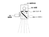
先ず、本発明の第1の実施形態について説明する。図1は、本発明の第1の実施形態に係るX線撮影装置の外観構成を示す図である。図1に示すように、本実施形態に係るX線撮影装置は、回診車100、X線照射部101、撮像部102、X線受光部103及び表示部104を備えており、回診車100の移動機構により移動することが可能である。
First, a first embodiment of the present invention will be described. FIG. 1 is a diagram showing an external configuration of an X-ray imaging apparatus according to the first embodiment of the present invention. As shown in FIG. 1, the X-ray imaging apparatus according to the present embodiment includes a round wheel 100, an
なお、本実施形態に係るX線撮影装置は、放射線の一種であるX線を照射し、被験者を透過したX線を検知することにより、放射線画像データを生成するものを想定している。但し、本発明に適用可能な放射線は、X線に限定されず、α線、β線又はγ線等の他の放射線も含まれる。つまり、本実施形態に係るX線撮影装置は、放射線撮影装置の一例である。 Note that the X-ray imaging apparatus according to the present embodiment is assumed to generate radiation image data by irradiating X-rays, which are a kind of radiation, and detecting X-rays transmitted through a subject. However, the radiation applicable to the present invention is not limited to X-rays, and includes other radiations such as α rays, β rays, and γ rays. That is, the X-ray imaging apparatus according to the present embodiment is an example of a radiation imaging apparatus.
回診車100の筐体内部には、X線撮影装置を制御するための制御装置が設けられている。制御装置は、CPU、ROM及びRAM等を備え、X線照射部101のX線照射や表示部104の画像表示等を制御するとともに、X線受光部103のX線照射部101に対する相対的な位置を検出する。
A control device for controlling the X-ray imaging apparatus is provided inside the casing of the round-trip vehicle 100. The control device includes a CPU, a ROM, a RAM, and the like, controls X-ray irradiation of the
X線照射部101は、X線管及びコリメータ(X線絞り)等によって構成されるX線を発生させるための機構を備える。撮像部102は、X線照射部101の内部に設けられたハーフミラーを介してX線管と共役な位置に配置され、X線の照射方向と略同方向を撮像するようになっている。X線受光部103は、X線照射部101によって照射されたX線を受光し、受光したX線に対応する電気信号を出力する一種の光電センサである。X線受光部103から出力された電気信号は、回診車100の筐体内部の制御装置に入力される。
The
表示部104は、CRTや液晶ディスプレイ等の一般的な表示モニタによって構成され、画像データやGUI(グラフィカルユーザインタフェース)等を画面に表示する。なお、X線撮影装置には、フットペダル、キーボード及びマウス(何れも不図示)といった、ユーザがX線撮影装置を操作及び制御するための入力装置が備えられている。
The
次に、図2を参照しながら、X線照射部101と撮像部102との位置関係について説明する。図2に示すように、X線照射部101は、X線を発生するX線管200と、X線管200で発生したX線の照射方向及び照射領域を限定するためのコリメータ201と、X線を透過し、可視光線を反射するハーフミラー202とを備える。撮像部102は、光学的にX線管200と同等な位置(共役な位置)に配置され、X線照射方向と略同方向を撮像することができる。なお、撮像部102がX線照射部101のX線照射方向と略同方向を撮像する方法は、これに限られない。例えば、撮像部102とX線照射部101とを極めて近接させて配置する方法や、特開平8−84351号公報に開示されるような、複数の撮像された画像データ及び補間画像データより、任意の視点及び方向の画像データを得る方法等を用いてもよい。
Next, the positional relationship between the
次に、回診車100の筐体内部に設けられている制御装置の機能的な構成について説明する。図3は、制御装置300の機能的な構成を示す図である。図3に示すように、制御装置300は、その機能的な構成として、位置検出部301、表示制御部302及び照射制御部303を備える。また、上述したように、制御装置300は、そのハードウェア構成として、CPU、ROM及びRAMを備えている。位置検出部301、表示制御部302及び照射制御部303は、CPUがROMから必要なデータ及びプログラムを読み込んでRAM上に展開し、実行することにより、実現する機能的な構成である。
Next, a functional configuration of the control device provided inside the casing of the round-wheel 100 will be described. FIG. 3 is a diagram illustrating a functional configuration of the
位置検出部301は、X線受光部103のX線照射部101に対する相対的な位置を検出する。表示制御部302は、X線受光部103から出力される電気信号に基づいて、いわゆるX線画像データを生成し、表示部104に表示させる。また、表示制御部302は、位置検出部301によって検出される、X線受光部103のX線照射部101に対する相対的な位置に基づいて、X線受光部103の仮想画像データを生成する。そして、表示制御部302は、撮像部102によって撮像される画像データにX線受光部103の仮想画像データを重畳し、表示部104に表示させる。照射制御部303は、X線照射部101に対する撮影開始及び終了(照射開始及び終了)やX線照射パターンの指示及び制御を行う。移動センサ304は、X線照射部101に連接して設けられ、X線照射部101の移動方向及び移動量を検出する。このような移動センサ304には、静電容量方式によるものや振動ジャイロ方式によるもの等、種々多様なものが実用可能に提供されている。
The
次に、図4及び図5を参照しながら、本発明の第1の実施形態に係るX線撮影装置の処理について説明する。図4は、本発明の第1の実施形態に係るX線撮影装置の処理を示すフローチャートである。図5は、X線受光部103の仮想画像データを説明するための図である。なお、図5のAは、撮像部102の撮像領域を示し、図5のBは、X線受光部103の仮想画像データを示している。
Next, processing of the X-ray imaging apparatus according to the first embodiment of the present invention will be described with reference to FIGS. 4 and 5. FIG. 4 is a flowchart showing processing of the X-ray imaging apparatus according to the first embodiment of the present invention. FIG. 5 is a diagram for explaining virtual image data of the X-ray
ステップS401において、照射制御部303は、図5(a)に示すように、コリメータ201により縦に絞られたX線501をX線照射部101からX線受光部103に対して照射させる。ステップS402において、表示制御部302は、X線を受光したX線受光部103から出力される電気信号に対して信号処理を施すことにより、図5(b)に示すようなX線501に対応する第1のX線画像データ502を生成する。なお、103´は、X線受光部103の仮想的な位置を示している。
In step S401, the
ステップS403において、照射制御部303は、図5(c)に示すように、コリメータ201により横に絞られたX線503をX線照射部101からX線受光部103に対して照射させる。ステップS404において、表示制御部302は、X線を受光したX線受光部103から出力される電気信号に対して信号処理を施すことにより、図5(d)に示すようなX線503に対応する第2のX線画像データ504を生成する。
In step S <b> 403, the
ステップS405において、表示制御部302は、図5(e)に示すように、第1のX線画像データ502と第2のX線画像データ504とがそれぞれの中心において直交するように合成する。ステップS406において、表示制御部302は、第1のX線画像データ502と第2のX線画像データ504との交点を、撮像部102の撮像領域Aの中心点と一致させる。これは、撮像部102がX線照射部101のX線照射方向と略同方向を撮像しているためである。ステップS407において、表示制御部302は、撮像部102の撮像画角(ズーム比率)とコリメータ201による絞りの値とを比較して、撮像領域Aにおける第1のX線画像データ502及び第2のX線画像データ504の大きさを定める。
In step S405, the
ステップS408において、表示制御部302は、図5(f)に示すように、撮像領域Aにおける第1のX線画像データ502及び第2のX線画像データ504の位置及び大きさに基づいて、撮像領域Aにおける仮想画像データBの位置及び大きさを計算する。そして、表示制御部302は、計算した撮像領域Aにおける仮想画像データBの位置及び大きさに基づいて、撮像部102によって撮像されている画像データに仮想画像データBを重畳させる。そして、表示制御部302は、仮想画像データBが重畳された画像データを表示部104に表示させる。
In step S408, the
ステップS409において、照射制御部303は、移動センサ304によって検知されるX線照射部101の移動方向及び移動量に基づいて、X線照射部101の位置が変更されたか否かを判定する。X線照射部101の位置が変更された場合、処理はステップS410に移行する。一方、X線照射部101の位置が変更されていない場合、処理はステップS409に戻り、X線照射部101の位置が変更されるまで待機する。なお、ステップS409は、位置検知手段の処理例である。
In step S409, the
ステップS410において、表示制御部302は、撮像領域Aにおける仮想画像データBの位置及び大きさを再計算する。ステップS411において、表示制御部302は、仮想画像データBを再描画して、撮像されている画像データに重畳し、表示部104に表示させる。ステップS412において、表示制御部302は、ユーザによる電源切断等の所定の終了条件を満たしたか否かを判定する。所定の終了条件を満たした場合、処理は終了する。一方、所定の終了条件を満たしていない場合、処理はステップS409に戻る。
In step S410, the
なお、上記の方法において、X線受光部103の位置を検出するために照射されるX線は、画像ノイズ等を考慮する必要が小さいため、医療診断用画像データを得るために照射されるX線と比較して微弱なものであって構わない。さらに、撮像領域AにおけるX線受光部103の位置を検出する方法は、上記の方法に限られない。例えば、X線照射部101及びX線受光部103それぞれにおいて、GPS(Global Positioning System)衛星から送信される衛星電波を介して測位情報を受信するとともに、姿勢角センサ(地磁気センサ等)により姿勢角を検出する。位置検出部301は、これらの測位情報及びに姿勢角情報に基づいて、X線受光部103のX線照射部101に対する相対的な位置を算出する。そして、位置検出部301は、X線受光部103のX線照射部101に対する相対的な位置と、撮像部102の撮像画角(ズーム比率)とに基づいて、撮像領域AにおけるX線受光部103の位置を検出する方法等もある。
In the above method, X-rays irradiated to detect the position of the X-ray
図6は、本実施形態に係るX線撮影装置の使用例を説明するための図である。図6(b)に示すように、本実施形態に係るX線撮影装置は、被験者の背部にX線受光部103を配置するとともに、X線照射部101のX線管200と共役な位置に配置された撮像部102によって、X線の照射方向と略同方向(被験者の胸部)を撮像する。すると、図6(a)に示すように、表示部104において、X線受光部103の仮想画像データBとX線照射範囲を示す仮想画像データCとが、撮像領域Aの画像データに重畳されて表示される。なお、撮像部102は、X線照射部101のX線照射方向と略同方向を撮像しているため、図6(a)に示すように、X線照射範囲を示す仮想画像データCの中心は、撮像範囲Aの中心と一致する。
FIG. 6 is a diagram for explaining a usage example of the X-ray imaging apparatus according to the present embodiment. As shown in FIG. 6 (b), the X-ray imaging apparatus according to the present embodiment has an X-ray
ここで、X線照射範囲を示す仮想画像データCの生成方法について説明する。図6(b)に示すように、撮像部102の撮像画角(ズーム比率)をθとし、コリメータ201による絞りの値により定まる照射角度をΦとする。さらに、撮像部102の横方向の撮像画角(ズーム比率)をθhとし、コリメータ201による絞りの値により定まる横方向の照射角度をΦhとした場合、X線照射範囲の横方向の長さの、撮像範囲A全体の横方向の長さに対する比率は、tanΦh/tanθhとなる。同様に、撮像部102の縦方向の撮像画角(ズーム比率)をθvとし、コリメータによる絞りの値により定まる縦方向の照射角度をΦvとした場合、X線照射範囲の縦方向の長さの、撮像範囲A全体の縦方向の長さに対する比率は、tanΦv/tanθvとなる。以上のようにして、撮像範囲AからX線照射範囲を求めることができ、X線照射範囲を示す仮想画像データCを生成することが可能となる。
Here, a method for generating virtual image data C indicating the X-ray irradiation range will be described. As shown in FIG. 6B, the imaging angle of view (zoom ratio) of the
本実施形態に係るX線撮影装置にいては、表示部104上に、撮像部102によって撮像されている撮像領域Aの画像データに対し、X線受光部103の仮想画像データBとX線照射範囲を示す仮想画像データCとを重畳させて表示することができる。従って、ユーザは、表示部104を参照しながら、X線照射部101の位置や向きを調整し、X線受光部103と対向させることが可能となる。
In the X-ray imaging apparatus according to the present embodiment, the virtual image data B of the X-ray
また、ユーザがコリメータ201による絞りの値を変更すると、これに合わせて、X線照射範囲を示す仮想画像データCの横方向及び縦方向のうちの少なくとも何れか一方の長さが変更される。従って、ユーザは、撮像部102によって撮像された撮像領域Aの画像データ中の被写体(患部)の大きさと、X線照射範囲を示す仮想画像データCとを同時に確認しながら、コリメータ201による絞りの値を調整することが可能となる。なお、上述したコリメータの絞り値の変更を検知する処理は、絞り値検知手段の処理例である。
When the user changes the aperture value by the collimator 201, the length of at least one of the horizontal direction and the vertical direction of the virtual image data C indicating the X-ray irradiation range is changed accordingly. Therefore, the user simultaneously checks the size of the subject (affected part) in the image data of the imaging area A imaged by the
次に、本発明の第2の実施形態について説明する。図7は、本発明の第2の実施形態に係るX線撮影装置の使用例を説明するための図である。本発明の第2の実施形態に係るX線撮影装置では、X線照射部101に表示部104が設けられており、ユーザが表示部104を参照しながら、X線照射部101の位置や向きを調整することができる。なお、表示部104がX線照射部101に設けられていること以外は、第1の実施形態と同様である。
Next, a second embodiment of the present invention will be described. FIG. 7 is a diagram for explaining an example of use of the X-ray imaging apparatus according to the second embodiment of the present invention. In the X-ray imaging apparatus according to the second embodiment of the present invention, the
次に、本発明の第3の実施形態について説明する。近年、上述したX線管に代わる電子源として、冷陰極型マルチ電子源を使用したX線照射部が知られている。このようなマルチ電子源を使用したX線照射部は、一つ一つの電子源を小さく構成して平面状に配列するため、全体として小型に構成することが可能となっている。また、マルチ電子源を使用したX線源は、複数の焦点を持つため、一度のX線照射によりX線受光部の位置検出のための所定の照射パターン(例えば、十字形)のX線照射が可能である。本発明の第3の実施形態に係るX線撮影装置は、図1に示すX線照射部101として、上述したマルチ電子源を使用したX線照射部を適用したものであり、その他の構成は、第1の実施形態に係るX線撮影装置と同様である。
Next, a third embodiment of the present invention will be described. In recent years, an X-ray irradiation unit using a cold cathode type multi-electron source is known as an electron source replacing the above-described X-ray tube. An X-ray irradiation unit using such a multi-electron source can be made compact as a whole because each electron source is configured to be small and arranged in a plane. In addition, since an X-ray source using a multi-electron source has a plurality of focal points, X-ray irradiation of a predetermined irradiation pattern (for example, a cross shape) for detecting the position of the X-ray light receiving unit by one X-ray irradiation. Is possible. The X-ray imaging apparatus according to the third embodiment of the present invention applies the X-ray irradiation unit using the above-described multi-electron source as the
図8は、本発明の第3実施形態に係るX線撮影装置の処理を示すフローチャートである。以下、図8を参照しながら、本発明の第3の実施形態に係るX線撮影装置の処理について詳細に説明する。 FIG. 8 is a flowchart showing processing of the X-ray imaging apparatus according to the third embodiment of the present invention. Hereinafter, the processing of the X-ray imaging apparatus according to the third embodiment of the present invention will be described in detail with reference to FIG.
ステップS801において、照射制御部303は、所定の照射パターン(例えば、十字形)のX線をX線照射部101からX線受光部103に照射させる。ステップS802において、表示制御部302は、X線を受光したX線受光部103から出力される電気信号に対して信号処理を施すことにより、X線画像データを生成する。ステップS803において、表示制御部302は、得られたX線画像データと上記所定の照射パターンとを比較して、撮像領域AにおけるX線画像データの位置及び大きさを定める。ステップS804において、表示制御部302は、上記X線画像データの位置及び大きさに基づいて、X線受光部103の仮想画像データBを撮像領域AにおけるX線画像データに重畳させ、表示部104において表示させる。なお、ステップS803及びS804は、図4のステップS407及びS408と同様の処理である。
In step S801, the
本発明の第3実施形態によれば、一度のX線照射によりX線受光部103の位置を検出するが可能であり、X線照射毎に絞りの値を変更する必要もないため、X線受光部103の位置を迅速に検出することが可能となる。
According to the third embodiment of the present invention, the position of the X-ray
また、本発明は、以下の処理を実行することによっても実現される。即ち、上述した実施形態の機能を実現するソフトウェア(プログラム)を、ネットワーク又は各種記憶媒体を介してシステム或いは装置に供給し、そのシステム或いは装置のコンピュータ(またはCPUやMPU等)がプログラムを読み出して実行する処理である。 The present invention can also be realized by executing the following processing. That is, software (program) that realizes the functions of the above-described embodiments is supplied to a system or apparatus via a network or various storage media, and a computer (or CPU, MPU, or the like) of the system or apparatus reads the program. It is a process to be executed.
100:回診車、101:X線照射部、102:撮像部102:X線受光部、104:表示部、200:X線管、201:コリメータ、202:ハーフミラー、300:制御装置、301:位置検出部、302:表示制御部、303:照射制御部、304:移動センサ DESCRIPTION OF SYMBOLS 100: Round-trip wheel, 101: X-ray irradiation part, 102: Imaging part 102: X-ray light-receiving part, 104: Display part, 200: X-ray tube, 201: Collimator, 202: Half mirror, 300: Control apparatus, 301: Position detection unit, 302: display control unit, 303: irradiation control unit, 304: movement sensor
Claims (12)
前記照射手段により照射された放射線を検出し、検出した放射線に対応する電気信号を出力する放射線検出手段と、
前記照射手段と前記放射線検出手段の位置及び姿勢角をそれぞれ検出し、前記放射線検出手段の前記照射手段に対する相対的な位置情報を算出する位置検出手段と、
前記照射手段の放射線照射方向と略同方向を撮像する撮像手段と、
前記照射手段の放射線照射範囲を示す画像データを生成し、前記放射線照射範囲を示す画像データと、前記位置検出手段により検出された前記放射線検出手段の前記照射手段に対する相対的な位置情報を示す画像データと、前記撮像手段により撮像された画像データと、を重畳して表示手段に表示させる表示制御手段と
を有することを特徴とする放射線撮影装置。 Irradiation means capable of irradiating radiation and adjusting the position and posture angle;
A radiation detecting device for outputting an electric signal to detect the radiation irradiated, corresponding to the detected radiation by the irradiation unit,
Position detection means for detecting the position and the posture angle of the irradiation means and the radiation detection means, respectively, and calculating relative position information of the radiation detection means with respect to the irradiation means ;
An image pickup means for picking up an image in substantially the same direction as a radiation irradiation direction of the irradiation means;
Image data indicating the radiation irradiation range of the irradiation unit is generated, image data indicating the radiation irradiation range, and an image indicating relative position information of the radiation detection unit detected by the position detection unit with respect to the irradiation unit data and, before Symbol radiographic apparatus, characterized in that it comprises a display control means for displaying on the display means by superimposing the image data captured, the by the imaging means.
前記位置検出手段は、前記位置検知手段により前記照射手段の位置の変更が検知された場合に、前記放射線検出手段の位置を再び検出することを特徴とする請求項1に記載の放射線撮影装置。 It further has a position detection means for detecting a change in the position of the irradiation means,
The radiation imaging apparatus according to claim 1, wherein the position detection unit detects the position of the radiation detection unit again when a change in the position of the irradiation unit is detected by the position detection unit.
前記表示制御手段は、前記絞り値検知手段により検知される前記コリメータの絞り値に応じて、前記照射手段の放射線照射範囲に係る画像データを変更することを特徴とする請求項1に記載の放射線撮影装置。 Further comprising aperture value detection means for detecting the aperture value of the collimator of the irradiation means,
2. The radiation according to claim 1, wherein the display control unit changes image data related to a radiation irradiation range of the irradiation unit according to the aperture value of the collimator detected by the aperture value detection unit. Shooting device.
前記照射手段により照射された放射線を検出し、検出した放射線に対応する電気信号を出力する放射線検出手段と、
前記照射手段と前記放射線検出手段の位置及び姿勢角をそれぞれ検出し、前記放射線検出手段の前記照射手段に対する相対的な位置情報を算出する位置検出手段と、
前記位置検出手段により検出された前記放射線検出手段の前記照射手段に対する相対的な位置情報を示す画像データと、前記照射手段の放射線照射範囲を示す画像データと、を重畳して表示手段に表示させる表示制御手段と
を有することを特徴とする放射線撮影装置。 Irradiation means capable of irradiating radiation and adjusting the position and posture angle;
A radiation detecting device for outputting an electric signal to detect the radiation irradiated, corresponding to the detected radiation by the irradiation unit,
Position detection means for detecting the position and the posture angle of the irradiation means and the radiation detection means, respectively, and calculating relative position information of the radiation detection means with respect to the irradiation means ;
Image data indicating relative position information of the radiation detection means detected by the position detection means with respect to the irradiation means and image data indicating a radiation irradiation range of the irradiation means are superimposed and displayed on the display means. A radiation imaging apparatus comprising: a display control unit.
前記位置検出手段は、前記位置検知手段により前記照射手段の位置の変更が検知された場合に、撮像手段による撮像範囲内における前記放射線検出手段の位置を再び検出することを特徴とする請求項6に記載の放射線撮影装置。 It further has a position detection means for detecting a change in the position of the irradiation means,
The position detection means detects again the position of the radiation detection means within an imaging range by the imaging means when a change in the position of the irradiation means is detected by the position detection means. The radiation imaging apparatus described in 1.
前記表示制御手段は、前記絞り値検知手段により検知される前記コリメータの絞り値に応じて、前記照射手段の放射線照射範囲を示す画像データを変更することを特徴とする請求項6に記載の放射線撮影装置。 Further comprising aperture value detection means for detecting the aperture value of the collimator of the irradiation means,
The radiation according to claim 6, wherein the display control unit changes image data indicating a radiation irradiation range of the irradiation unit according to the aperture value of the collimator detected by the aperture value detection unit. Shooting device.
放射線を照射すると共に、位置及び姿勢角を調整することが可能な照射手段と、前記照射手段により照射された放射線を検出する手段であり、かつ検出した放射線に対応する電気信号を出力する手段である放射線検出手段の位置及び姿勢角をそれぞれ検出し、前記放射線検出手段の前記照射手段に対する相対的な位置情報を算出する位置検出ステップと、
前記照射手段の放射線照射方向と略同方向を撮像する撮像ステップと、
前記照射手段の放射線照射範囲を示す画像データを生成し、前記放射線照射範囲を示す画像データと、前記位置検出ステップにおいて検出された前記放射線検出手段の前記照射手段に対する相対的な位置情報を示す画像データと、前記撮像ステップにおいて撮像された画像データと、を重畳して表示手段に表示させる表示制御ステップと
を含むことを特徴とする放射線撮影装置の制御方法。 A control method executed by the radiation imaging apparatus,
An irradiating means capable of irradiating radiation and adjusting a position and an attitude angle; a means for detecting the radiation irradiated by the irradiating means; and a means for outputting an electrical signal corresponding to the detected radiation. A position detection step of detecting a position and an attitude angle of a certain radiation detection unit, and calculating relative position information of the radiation detection unit with respect to the irradiation unit ;
An imaging step of imaging in substantially the same direction as the radiation irradiation direction of the irradiation means;
Image data indicating the radiation irradiation range of the irradiation unit is generated, and image data indicating the radiation irradiation range and an image indicating relative position information of the radiation detection unit detected in the position detection step with respect to the irradiation unit. data and, before Symbol method of controlling a radiation imaging apparatus which comprises a display control step of displaying on the display means by superimposing the image data captured, the at imaging step.
放射線を照射すると共に、位置及び姿勢角を調整することが可能な照射手段と、前記照射手段により照射された放射線を検出する手段であり、かつ検出した放射線に対応する電気信号を出力する手段である放射線検出手段の位置及び姿勢角をそれぞれ検出し、前記放射線検出手段の前記照射手段に対する相対的な位置情報を算出する位置検出ステップと、
前記位置検出ステップにおいて検出された前記放射線検出手段の前記照射手段に対する相対的な位置情報を示す画像データと、前記照射手段の放射線照射範囲を示す画像データと、を重畳して表示手段に表示させる表示制御ステップと
を含むことを特徴とする放射線撮影装置の制御方法。 A control method executed by the radiation imaging apparatus,
An irradiating means capable of irradiating radiation and adjusting a position and an attitude angle; a means for detecting the radiation irradiated by the irradiating means; and a means for outputting an electrical signal corresponding to the detected radiation. A position detection step of detecting a position and an attitude angle of a certain radiation detection unit, and calculating relative position information of the radiation detection unit with respect to the irradiation unit ;
Image data indicating relative position information of the radiation detection means detected in the position detection step with respect to the irradiation means and image data indicating the radiation irradiation range of the irradiation means are superimposed and displayed on the display means. A control method for the radiation imaging apparatus, comprising: a display control step.
請求項9又は10に記載の制御方法の各ステップを実行させるためのプログラム。 On the computer,
The program for performing each step of the control method of Claim 9 or 10.
Priority Applications (2)
| Application Number | Priority Date | Filing Date | Title |
|---|---|---|---|
| JP2012093983A JP6112773B2 (en) | 2012-04-17 | 2012-04-17 | Radiation imaging apparatus, control method thereof, and program |
| US13/862,778 US9125623B2 (en) | 2012-04-17 | 2013-04-15 | Radiographic imaging apparatus, control method therefor, and storage medium having stored program |
Applications Claiming Priority (1)
| Application Number | Priority Date | Filing Date | Title |
|---|---|---|---|
| JP2012093983A JP6112773B2 (en) | 2012-04-17 | 2012-04-17 | Radiation imaging apparatus, control method thereof, and program |
Publications (3)
| Publication Number | Publication Date |
|---|---|
| JP2013220218A JP2013220218A (en) | 2013-10-28 |
| JP2013220218A5 JP2013220218A5 (en) | 2015-05-07 |
| JP6112773B2 true JP6112773B2 (en) | 2017-04-12 |
Family
ID=49325110
Family Applications (1)
| Application Number | Title | Priority Date | Filing Date |
|---|---|---|---|
| JP2012093983A Active JP6112773B2 (en) | 2012-04-17 | 2012-04-17 | Radiation imaging apparatus, control method thereof, and program |
Country Status (2)
| Country | Link |
|---|---|
| US (1) | US9125623B2 (en) |
| JP (1) | JP6112773B2 (en) |
Families Citing this family (10)
| Publication number | Priority date | Publication date | Assignee | Title |
|---|---|---|---|---|
| US10285656B2 (en) * | 2010-10-18 | 2019-05-14 | Carestream Health, Inc. | X-ray imaging system and method |
| JP6277951B2 (en) * | 2014-12-24 | 2018-02-14 | 株式会社島津製作所 | X-ray equipment |
| JP2016193177A (en) * | 2015-03-31 | 2016-11-17 | 富士フイルム株式会社 | Radiation irradiation device |
| JP6412044B2 (en) * | 2015-05-11 | 2018-10-24 | 富士フイルム株式会社 | Radiographic imaging apparatus, and radiographic imaging apparatus control method and program |
| WO2016208155A1 (en) * | 2015-06-22 | 2016-12-29 | 富士フイルム株式会社 | Radiation-irradiating device, control method for radiation-irradiating device, and program |
| CN107708564B (en) | 2015-07-07 | 2021-11-05 | 富士胶片株式会社 | Radiographic imaging device, control method for radiographic imaging device, and recording medium |
| JP6632847B2 (en) * | 2015-09-28 | 2020-01-22 | キヤノンメディカルシステムズ株式会社 | X-ray diagnostic equipment |
| JP6830402B2 (en) * | 2017-04-27 | 2021-02-17 | 富士電機株式会社 | X-ray inspection system and X-ray irradiation device |
| CN112770673A (en) * | 2018-09-27 | 2021-05-07 | 富士胶片株式会社 | Radiographic apparatus |
| JP2020141748A (en) * | 2019-03-04 | 2020-09-10 | 富士フイルム株式会社 | Rounding imaging management apparatus, method of operating rounding imaging management apparatus, program for operating rounding imaging management apparatus, data structure, and recording apparatus |
Family Cites Families (30)
| Publication number | Priority date | Publication date | Assignee | Title |
|---|---|---|---|---|
| JP3456718B2 (en) * | 1993-01-27 | 2003-10-14 | 株式会社東芝 | X-ray equipment |
| JPH0966116A (en) | 1995-08-31 | 1997-03-11 | Shimadzu Corp | Index light radiating device for marking assist in radiotherapeutic program |
| DE19729414A1 (en) * | 1997-07-09 | 1999-02-11 | Siemens Ag | Medical radiation screening system |
| DE19837512A1 (en) * | 1998-08-19 | 2000-02-24 | Philips Corp Intellectual Pty | X-ray examination device with an aperture unit |
| JP3624106B2 (en) | 1998-10-29 | 2005-03-02 | キヤノン株式会社 | Digital photography stand |
| US6260999B1 (en) * | 1999-07-26 | 2001-07-17 | Siemens Medical Systems, Inc. | Isocenter localization using electronic portal imaging |
| US6473489B2 (en) * | 1999-09-30 | 2002-10-29 | Siemens Corporate Research, Inc | Apparatus for superimposition of X-ray and video images |
| US6227704B1 (en) * | 1999-09-30 | 2001-05-08 | Siemens Corporate Research, Inc. | Laser-based method for aligning apparatus for superimposing X-ray and video images |
| US6463121B1 (en) * | 1999-10-13 | 2002-10-08 | General Electric Company | Interactive x-ray position and exposure control using image data as reference information |
| US6757355B1 (en) * | 2000-08-17 | 2004-06-29 | Siemens Medical Solutions Usa, Inc. | High definition radiation treatment with an intensity modulating multi-leaf collimator |
| US6447164B1 (en) * | 2000-09-07 | 2002-09-10 | Ge Medical Systems Global Technology Company, Llc | X-ray imaging system with viewable beam angulation adjustment |
| JP2002143139A (en) * | 2000-11-15 | 2002-05-21 | Fuji Photo Film Co Ltd | Portable radiographic system and radiographic image detector to be used for the system |
| US6478462B2 (en) * | 2001-02-20 | 2002-11-12 | Ge Medical Systems Global Technology Company, Llc | Methodology for determining x-ray to light field decentering on digital radiographic image systems |
| JP3647440B2 (en) * | 2002-05-28 | 2005-05-11 | キヤノン株式会社 | X-ray equipment |
| JP4149230B2 (en) * | 2002-10-16 | 2008-09-10 | 富士フイルム株式会社 | Radiographic imaging system and radiographic image detector |
| US7522701B2 (en) * | 2005-12-20 | 2009-04-21 | General Electric Company | System and method for image composition using position sensors |
| US7555100B2 (en) * | 2006-12-20 | 2009-06-30 | Carestream Health, Inc. | Long length imaging using digital radiography |
| JP5196798B2 (en) * | 2007-02-15 | 2013-05-15 | キヤノン株式会社 | Radiation image projection apparatus and method |
| JP5143471B2 (en) * | 2007-05-08 | 2013-02-13 | 株式会社日立製作所 | Imaging device |
| US7572057B2 (en) * | 2007-06-21 | 2009-08-11 | Canon Kabushiki Kaisha | Radiography control apparatus and radiography control method |
| JP4946677B2 (en) * | 2007-07-06 | 2012-06-06 | コニカミノルタホールディングス株式会社 | Transmission image photographing system and transmission image photographing method |
| DE102007034218B4 (en) * | 2007-07-23 | 2013-06-13 | Siemens Aktiengesellschaft | Apparatus and method for image composition |
| JP5398133B2 (en) * | 2007-10-23 | 2014-01-29 | キヤノン株式会社 | X-ray imaging apparatus, control method for X-ray imaging apparatus, program, and storage medium |
| JP5209935B2 (en) * | 2007-10-23 | 2013-06-12 | キヤノン株式会社 | X-ray imaging apparatus, control method for X-ray imaging apparatus, program, and storage medium |
| JP2009131323A (en) * | 2007-11-28 | 2009-06-18 | Canon Inc | Imaging apparatus |
| JP4693884B2 (en) * | 2008-09-18 | 2011-06-01 | キヤノン株式会社 | Multi X-ray imaging apparatus and control method thereof |
| JP2010075245A (en) * | 2008-09-24 | 2010-04-08 | Fujifilm Corp | Radiographic imaging apparatus |
| US8678648B2 (en) * | 2010-04-13 | 2014-03-25 | Carestream Health, Inc. | Mobile radiography unit having single sign on and methods for using the same |
| US8622614B2 (en) * | 2010-08-23 | 2014-01-07 | Carestream Health, Inc. | Locking device for mobile X-ray system |
| US8891734B2 (en) * | 2011-10-12 | 2014-11-18 | Carestream Health, Inc. | Portable digital radiography detector loss prevention |
-
2012
- 2012-04-17 JP JP2012093983A patent/JP6112773B2/en active Active
-
2013
- 2013-04-15 US US13/862,778 patent/US9125623B2/en active Active
Also Published As
| Publication number | Publication date |
|---|---|
| US9125623B2 (en) | 2015-09-08 |
| JP2013220218A (en) | 2013-10-28 |
| US20130272502A1 (en) | 2013-10-17 |
Similar Documents
| Publication | Publication Date | Title |
|---|---|---|
| JP6112773B2 (en) | Radiation imaging apparatus, control method thereof, and program | |
| US9949707B2 (en) | Radiographic imaging system, control method, and storage medium | |
| JP5376766B2 (en) | X-ray imaging apparatus, X-ray imaging method, and X-ray image display method | |
| US20120050277A1 (en) | Stereoscopic image displaying method and device | |
| JP5702236B2 (en) | X-ray imaging apparatus and calibration method thereof | |
| US20140093036A1 (en) | Tomographic image generation device and method | |
| CN103327897A (en) | Mobile x-ray apparatus | |
| JP4561990B2 (en) | X-ray equipment | |
| JP5658209B2 (en) | X-ray imaging apparatus, X-ray imaging method, and X-ray image display method | |
| US20120027170A1 (en) | Radiological image capturing and displaying method and apparatus | |
| US20120027169A1 (en) | Radiological image radiographing and displaying method and apparatus | |
| US20120027168A1 (en) | Radiological image radiographing and displaying method and radiological image radiographing and displaying apparatus | |
| CN105407803A (en) | Method for imaging by means of an X-ray appliance, and X-ray appliance | |
| JP5506726B2 (en) | Radiation image capturing method, radiation detector, and radiation image capturing apparatus | |
| JP2012115380A (en) | Stereoscopic image acquiring method and apparatus | |
| WO2012105188A1 (en) | Stereoscopic image display device and method, and program | |
| JP2012050517A (en) | Radiographic apparatus | |
| JP2017006595A (en) | Image processing apparatus, tomographic image generation system, and program | |
| WO2012132320A1 (en) | Stereoscopic image display apparatus and stereoscopic image display method | |
| US20120025088A1 (en) | Radiological image radiographing and displaying method and apparatus | |
| JP2012050518A (en) | Radiation imaging apparatus | |
| WO2012056693A1 (en) | Distance measurement/display method and device, and 3d image display method and device | |
| WO2012029726A1 (en) | Method and apparatus for imaging/displaying breast image | |
| JP2012095274A (en) | Stereoscopic image display device and stereoscopic image display method | |
| JP2013202058A (en) | Radiographic imaging and displaying system, and method thereof |
Legal Events
| Date | Code | Title | Description |
|---|---|---|---|
| A521 | Request for written amendment filed |
Free format text: JAPANESE INTERMEDIATE CODE: A523 Effective date: 20150320 |
|
| A621 | Written request for application examination |
Free format text: JAPANESE INTERMEDIATE CODE: A621 Effective date: 20150320 |
|
| A977 | Report on retrieval |
Free format text: JAPANESE INTERMEDIATE CODE: A971007 Effective date: 20160128 |
|
| A131 | Notification of reasons for refusal |
Free format text: JAPANESE INTERMEDIATE CODE: A131 Effective date: 20160223 |
|
| A521 | Request for written amendment filed |
Free format text: JAPANESE INTERMEDIATE CODE: A523 Effective date: 20160315 |
|
| A131 | Notification of reasons for refusal |
Free format text: JAPANESE INTERMEDIATE CODE: A131 Effective date: 20160913 |
|
| A521 | Request for written amendment filed |
Free format text: JAPANESE INTERMEDIATE CODE: A523 Effective date: 20160927 |
|
| TRDD | Decision of grant or rejection written | ||
| A01 | Written decision to grant a patent or to grant a registration (utility model) |
Free format text: JAPANESE INTERMEDIATE CODE: A01 Effective date: 20170214 |
|
| A61 | First payment of annual fees (during grant procedure) |
Free format text: JAPANESE INTERMEDIATE CODE: A61 Effective date: 20170314 |
|
| R151 | Written notification of patent or utility model registration |
Ref document number: 6112773 Country of ref document: JP Free format text: JAPANESE INTERMEDIATE CODE: R151 |