JP6110595B2 - Manufacturing method of polarizing plastic lens for spectacles - Google Patents
Manufacturing method of polarizing plastic lens for spectacles Download PDFInfo
- Publication number
- JP6110595B2 JP6110595B2 JP2012024252A JP2012024252A JP6110595B2 JP 6110595 B2 JP6110595 B2 JP 6110595B2 JP 2012024252 A JP2012024252 A JP 2012024252A JP 2012024252 A JP2012024252 A JP 2012024252A JP 6110595 B2 JP6110595 B2 JP 6110595B2
- Authority
- JP
- Japan
- Prior art keywords
- lens
- polarizing film
- mold
- polarizing
- plastic lens
- Prior art date
- Legal status (The legal status is an assumption and is not a legal conclusion. Google has not performed a legal analysis and makes no representation as to the accuracy of the status listed.)
- Active
Links
- 229920003023 plastic Polymers 0.000 title claims description 96
- 239000004033 plastic Substances 0.000 title claims description 95
- 238000004519 manufacturing process Methods 0.000 title claims description 25
- 239000000758 substrate Substances 0.000 claims description 44
- 239000000853 adhesive Substances 0.000 claims description 34
- 230000001070 adhesive effect Effects 0.000 claims description 33
- 239000000463 material Substances 0.000 claims description 30
- 230000002093 peripheral effect Effects 0.000 claims description 17
- 239000002994 raw material Substances 0.000 claims description 10
- 239000000203 mixture Substances 0.000 claims description 8
- 239000000178 monomer Substances 0.000 description 31
- 239000011347 resin Substances 0.000 description 17
- 229920005989 resin Polymers 0.000 description 17
- 210000005252 bulbus oculi Anatomy 0.000 description 16
- 239000004372 Polyvinyl alcohol Substances 0.000 description 15
- 229920002451 polyvinyl alcohol Polymers 0.000 description 15
- 238000000034 method Methods 0.000 description 12
- 230000000052 comparative effect Effects 0.000 description 10
- 238000005498 polishing Methods 0.000 description 9
- 239000011521 glass Substances 0.000 description 8
- 238000010438 heat treatment Methods 0.000 description 8
- 238000000465 moulding Methods 0.000 description 8
- 239000002390 adhesive tape Substances 0.000 description 7
- 229920002284 Cellulose triacetate Polymers 0.000 description 5
- NNLVGZFZQQXQNW-ADJNRHBOSA-N [(2r,3r,4s,5r,6s)-4,5-diacetyloxy-3-[(2s,3r,4s,5r,6r)-3,4,5-triacetyloxy-6-(acetyloxymethyl)oxan-2-yl]oxy-6-[(2r,3r,4s,5r,6s)-4,5,6-triacetyloxy-2-(acetyloxymethyl)oxan-3-yl]oxyoxan-2-yl]methyl acetate Chemical compound O([C@@H]1O[C@@H]([C@H]([C@H](OC(C)=O)[C@H]1OC(C)=O)O[C@H]1[C@@H]([C@@H](OC(C)=O)[C@H](OC(C)=O)[C@@H](COC(C)=O)O1)OC(C)=O)COC(=O)C)[C@@H]1[C@@H](COC(C)=O)O[C@@H](OC(C)=O)[C@H](OC(C)=O)[C@H]1OC(C)=O NNLVGZFZQQXQNW-ADJNRHBOSA-N 0.000 description 5
- 239000010410 layer Substances 0.000 description 5
- 238000012545 processing Methods 0.000 description 5
- 239000011241 protective layer Substances 0.000 description 5
- VSSFYDMUTATOHG-UHFFFAOYSA-N 2-(2-sulfanylethylsulfanyl)-3-[3-sulfanyl-2-(2-sulfanylethylsulfanyl)propyl]sulfanylpropane-1-thiol Chemical compound SCCSC(CS)CSCC(CS)SCCS VSSFYDMUTATOHG-UHFFFAOYSA-N 0.000 description 4
- ZCYVEMRRCGMTRW-UHFFFAOYSA-N 7553-56-2 Chemical compound [I] ZCYVEMRRCGMTRW-UHFFFAOYSA-N 0.000 description 4
- 238000002347 injection Methods 0.000 description 4
- 239000007924 injection Substances 0.000 description 4
- 238000003780 insertion Methods 0.000 description 4
- 230000037431 insertion Effects 0.000 description 4
- 229910052740 iodine Inorganic materials 0.000 description 4
- 239000011630 iodine Substances 0.000 description 4
- 239000006082 mold release agent Substances 0.000 description 4
- 238000002360 preparation method Methods 0.000 description 4
- 238000003756 stirring Methods 0.000 description 4
- 125000005068 thioepoxy group Chemical group S(O*)* 0.000 description 4
- 239000003054 catalyst Substances 0.000 description 3
- 238000010586 diagram Methods 0.000 description 3
- 239000000975 dye Substances 0.000 description 3
- 239000007788 liquid Substances 0.000 description 3
- -1 polyethylene terephthalate Polymers 0.000 description 3
- 239000005020 polyethylene terephthalate Substances 0.000 description 3
- 229920000139 polyethylene terephthalate Polymers 0.000 description 3
- 239000002356 single layer Substances 0.000 description 3
- 239000000126 substance Substances 0.000 description 3
- 239000006097 ultraviolet radiation absorber Substances 0.000 description 3
- JRKRMWWBDZSDMT-UHFFFAOYSA-N 2-[(thiiran-2-ylmethyldisulfanyl)methyl]thiirane Chemical compound C1SC1CSSCC1CS1 JRKRMWWBDZSDMT-UHFFFAOYSA-N 0.000 description 2
- OCGYTRZLSMAPQC-UHFFFAOYSA-N 3-(2-sulfanylethylsulfanyl)-2-[1-sulfanyl-3-(2-sulfanylethylsulfanyl)propan-2-yl]sulfanylpropane-1-thiol Chemical compound SCCSCC(CS)SC(CS)CSCCS OCGYTRZLSMAPQC-UHFFFAOYSA-N 0.000 description 2
- 230000015572 biosynthetic process Effects 0.000 description 2
- 230000008859 change Effects 0.000 description 2
- 150000001875 compounds Chemical class 0.000 description 2
- 238000005520 cutting process Methods 0.000 description 2
- RJGHQTVXGKYATR-UHFFFAOYSA-L dibutyl(dichloro)stannane Chemical compound CCCC[Sn](Cl)(Cl)CCCC RJGHQTVXGKYATR-UHFFFAOYSA-L 0.000 description 2
- 239000003822 epoxy resin Substances 0.000 description 2
- 210000001508 eye Anatomy 0.000 description 2
- 230000001678 irradiating effect Effects 0.000 description 2
- 239000011159 matrix material Substances 0.000 description 2
- 238000002156 mixing Methods 0.000 description 2
- 238000007517 polishing process Methods 0.000 description 2
- 229920000647 polyepoxide Polymers 0.000 description 2
- 229920006295 polythiol Polymers 0.000 description 2
- 238000003825 pressing Methods 0.000 description 2
- 230000008569 process Effects 0.000 description 2
- 239000000523 sample Substances 0.000 description 2
- 238000004381 surface treatment Methods 0.000 description 2
- XLYOFNOQVPJJNP-UHFFFAOYSA-N water Substances O XLYOFNOQVPJJNP-UHFFFAOYSA-N 0.000 description 2
- RTTZISZSHSCFRH-UHFFFAOYSA-N 1,3-bis(isocyanatomethyl)benzene Chemical compound O=C=NCC1=CC=CC(CN=C=O)=C1 RTTZISZSHSCFRH-UHFFFAOYSA-N 0.000 description 1
- CEUQYYYUSUCFKP-UHFFFAOYSA-N 2,3-bis(2-sulfanylethylsulfanyl)propane-1-thiol Chemical compound SCCSCC(CS)SCCS CEUQYYYUSUCFKP-UHFFFAOYSA-N 0.000 description 1
- IYAZLDLPUNDVAG-UHFFFAOYSA-N 2-(benzotriazol-2-yl)-4-(2,4,4-trimethylpentan-2-yl)phenol Chemical compound CC(C)(C)CC(C)(C)C1=CC=C(O)C(N2N=C3C=CC=CC3=N2)=C1 IYAZLDLPUNDVAG-UHFFFAOYSA-N 0.000 description 1
- 125000003903 2-propenyl group Chemical group [H]C([*])([H])C([H])=C([H])[H] 0.000 description 1
- BYPFICORERPGJY-UHFFFAOYSA-N 3,4-diisocyanatobicyclo[2.2.1]hept-2-ene Chemical compound C1CC2(N=C=O)C(N=C=O)=CC1C2 BYPFICORERPGJY-UHFFFAOYSA-N 0.000 description 1
- NXYWIOFCVGCOCB-UHFFFAOYSA-N 3-(2-sulfanylethylsulfanyl)-2-[3-sulfanyl-2-(2-sulfanylethylsulfanyl)propyl]sulfanylpropane-1-thiol Chemical compound SCCSCC(CS)SCC(CS)SCCS NXYWIOFCVGCOCB-UHFFFAOYSA-N 0.000 description 1
- HZKNDOAKHOSZRY-UHFFFAOYSA-N 3-[2-[2-(2-sulfanylethylsulfanyl)ethylsulfanyl]ethylsulfanyl]propane-1,2-dithiol Chemical compound SCCSCCSCCSCC(S)CS HZKNDOAKHOSZRY-UHFFFAOYSA-N 0.000 description 1
- 239000004925 Acrylic resin Substances 0.000 description 1
- 229920000178 Acrylic resin Polymers 0.000 description 1
- 244000043261 Hevea brasiliensis Species 0.000 description 1
- SVYKKECYCPFKGB-UHFFFAOYSA-N N,N-dimethylcyclohexylamine Chemical compound CN(C)C1CCCCC1 SVYKKECYCPFKGB-UHFFFAOYSA-N 0.000 description 1
- 239000004743 Polypropylene Substances 0.000 description 1
- 239000004820 Pressure-sensitive adhesive Substances 0.000 description 1
- JOBBTVPTPXRUBP-UHFFFAOYSA-N [3-(3-sulfanylpropanoyloxy)-2,2-bis(3-sulfanylpropanoyloxymethyl)propyl] 3-sulfanylpropanoate Chemical compound SCCC(=O)OCC(COC(=O)CCS)(COC(=O)CCS)COC(=O)CCS JOBBTVPTPXRUBP-UHFFFAOYSA-N 0.000 description 1
- NIXOWILDQLNWCW-UHFFFAOYSA-N acrylic acid group Chemical group C(C=C)(=O)O NIXOWILDQLNWCW-UHFFFAOYSA-N 0.000 description 1
- 239000000654 additive Substances 0.000 description 1
- 230000000996 additive effect Effects 0.000 description 1
- 239000012790 adhesive layer Substances 0.000 description 1
- 230000008901 benefit Effects 0.000 description 1
- 239000011248 coating agent Substances 0.000 description 1
- 238000000576 coating method Methods 0.000 description 1
- 239000005331 crown glasses (windows) Substances 0.000 description 1
- 238000013461 design Methods 0.000 description 1
- 230000004438 eyesight Effects 0.000 description 1
- 238000000227 grinding Methods 0.000 description 1
- 239000003999 initiator Substances 0.000 description 1
- 238000010030 laminating Methods 0.000 description 1
- 238000005259 measurement Methods 0.000 description 1
- 239000000113 methacrylic resin Substances 0.000 description 1
- 238000012986 modification Methods 0.000 description 1
- 230000004048 modification Effects 0.000 description 1
- 229920003052 natural elastomer Polymers 0.000 description 1
- 229920001194 natural rubber Polymers 0.000 description 1
- 239000003921 oil Substances 0.000 description 1
- 230000010287 polarization Effects 0.000 description 1
- 229920005668 polycarbonate resin Polymers 0.000 description 1
- 239000004431 polycarbonate resin Substances 0.000 description 1
- 238000006116 polymerization reaction Methods 0.000 description 1
- 230000000379 polymerizing effect Effects 0.000 description 1
- 229920001155 polypropylene Polymers 0.000 description 1
- 230000000750 progressive effect Effects 0.000 description 1
- 230000002940 repellent Effects 0.000 description 1
- 239000005871 repellent Substances 0.000 description 1
- 230000004044 response Effects 0.000 description 1
- 238000007493 shaping process Methods 0.000 description 1
- 229910052710 silicon Inorganic materials 0.000 description 1
- 239000010703 silicon Substances 0.000 description 1
- 239000007787 solid Substances 0.000 description 1
- 239000000243 solution Substances 0.000 description 1
- 229920003002 synthetic resin Polymers 0.000 description 1
- 239000000057 synthetic resin Substances 0.000 description 1
- 229920001187 thermosetting polymer Polymers 0.000 description 1
- 150000003553 thiiranes Chemical class 0.000 description 1
Images


Classifications
-
- B—PERFORMING OPERATIONS; TRANSPORTING
- B29—WORKING OF PLASTICS; WORKING OF SUBSTANCES IN A PLASTIC STATE IN GENERAL
- B29D—PRODUCING PARTICULAR ARTICLES FROM PLASTICS OR FROM SUBSTANCES IN A PLASTIC STATE
- B29D11/00—Producing optical elements, e.g. lenses or prisms
- B29D11/00009—Production of simple or compound lenses
- B29D11/00403—Producing compound lenses
-
- B—PERFORMING OPERATIONS; TRANSPORTING
- B29—WORKING OF PLASTICS; WORKING OF SUBSTANCES IN A PLASTIC STATE IN GENERAL
- B29C—SHAPING OR JOINING OF PLASTICS; SHAPING OF MATERIAL IN A PLASTIC STATE, NOT OTHERWISE PROVIDED FOR; AFTER-TREATMENT OF THE SHAPED PRODUCTS, e.g. REPAIRING
- B29C39/00—Shaping by casting, i.e. introducing the moulding material into a mould or between confining surfaces without significant moulding pressure; Apparatus therefor
- B29C39/22—Component parts, details or accessories; Auxiliary operations
- B29C39/24—Feeding the material into the mould
-
- B—PERFORMING OPERATIONS; TRANSPORTING
- B29—WORKING OF PLASTICS; WORKING OF SUBSTANCES IN A PLASTIC STATE IN GENERAL
- B29C—SHAPING OR JOINING OF PLASTICS; SHAPING OF MATERIAL IN A PLASTIC STATE, NOT OTHERWISE PROVIDED FOR; AFTER-TREATMENT OF THE SHAPED PRODUCTS, e.g. REPAIRING
- B29C39/00—Shaping by casting, i.e. introducing the moulding material into a mould or between confining surfaces without significant moulding pressure; Apparatus therefor
- B29C39/22—Component parts, details or accessories; Auxiliary operations
- B29C39/26—Moulds or cores
-
- B—PERFORMING OPERATIONS; TRANSPORTING
- B29—WORKING OF PLASTICS; WORKING OF SUBSTANCES IN A PLASTIC STATE IN GENERAL
- B29D—PRODUCING PARTICULAR ARTICLES FROM PLASTICS OR FROM SUBSTANCES IN A PLASTIC STATE
- B29D11/00—Producing optical elements, e.g. lenses or prisms
- B29D11/00634—Production of filters
- B29D11/00644—Production of filters polarizing
-
- B—PERFORMING OPERATIONS; TRANSPORTING
- B29—WORKING OF PLASTICS; WORKING OF SUBSTANCES IN A PLASTIC STATE IN GENERAL
- B29D—PRODUCING PARTICULAR ARTICLES FROM PLASTICS OR FROM SUBSTANCES IN A PLASTIC STATE
- B29D11/00—Producing optical elements, e.g. lenses or prisms
- B29D11/0073—Optical laminates
-
- G—PHYSICS
- G02—OPTICS
- G02B—OPTICAL ELEMENTS, SYSTEMS OR APPARATUS
- G02B5/00—Optical elements other than lenses
- G02B5/30—Polarising elements
- G02B5/3025—Polarisers, i.e. arrangements capable of producing a definite output polarisation state from an unpolarised input state
- G02B5/3033—Polarisers, i.e. arrangements capable of producing a definite output polarisation state from an unpolarised input state in the form of a thin sheet or foil, e.g. Polaroid
- G02B5/3041—Polarisers, i.e. arrangements capable of producing a definite output polarisation state from an unpolarised input state in the form of a thin sheet or foil, e.g. Polaroid comprising multiple thin layers, e.g. multilayer stacks
- G02B5/305—Polarisers, i.e. arrangements capable of producing a definite output polarisation state from an unpolarised input state in the form of a thin sheet or foil, e.g. Polaroid comprising multiple thin layers, e.g. multilayer stacks including organic materials, e.g. polymeric layers
-
- G—PHYSICS
- G02—OPTICS
- G02C—SPECTACLES; SUNGLASSES OR GOGGLES INSOFAR AS THEY HAVE THE SAME FEATURES AS SPECTACLES; CONTACT LENSES
- G02C7/00—Optical parts
- G02C7/12—Polarisers
-
- B—PERFORMING OPERATIONS; TRANSPORTING
- B29—WORKING OF PLASTICS; WORKING OF SUBSTANCES IN A PLASTIC STATE IN GENERAL
- B29D—PRODUCING PARTICULAR ARTICLES FROM PLASTICS OR FROM SUBSTANCES IN A PLASTIC STATE
- B29D11/00—Producing optical elements, e.g. lenses or prisms
- B29D11/00009—Production of simple or compound lenses
- B29D11/00413—Production of simple or compound lenses made by moulding between two mould parts which are not in direct contact with one another, e.g. comprising a seal between or on the edges
-
- B—PERFORMING OPERATIONS; TRANSPORTING
- B29—WORKING OF PLASTICS; WORKING OF SUBSTANCES IN A PLASTIC STATE IN GENERAL
- B29D—PRODUCING PARTICULAR ARTICLES FROM PLASTICS OR FROM SUBSTANCES IN A PLASTIC STATE
- B29D11/00—Producing optical elements, e.g. lenses or prisms
- B29D11/00009—Production of simple or compound lenses
- B29D11/0048—Moulds for lenses
- B29D11/00528—Consisting of two mould halves joined by an annular gasket
-
- G—PHYSICS
- G02—OPTICS
- G02C—SPECTACLES; SUNGLASSES OR GOGGLES INSOFAR AS THEY HAVE THE SAME FEATURES AS SPECTACLES; CONTACT LENSES
- G02C2202/00—Generic optical aspects applicable to one or more of the subgroups of G02C7/00
- G02C2202/16—Laminated or compound lenses
Description
本発明は、眼鏡用偏光プラスチックレンズおよび眼鏡用偏光プラスチックレンズの製造方法に関する。 The present invention relates to a polarizing plastic lens for spectacles and a method for manufacturing a polarizing plastic lens for spectacles.
従来、水面などにより反射された所定の偏光方向の光を遮断する偏光プラスチックレンズが知られている(例えば、特許文献1参照)。
偏光レンズとしては、2枚のレンズ基材の間に偏光フィルムを貼り合わせて構成されたプラスチック偏光レンズや、偏光フィルムの周囲に原料モノマーを注入してから重合硬化することによって、レンズ内部に偏光フィルムが埋設されたプラスチック偏光レンズが知られている。
2. Description of the Related Art Conventionally, a polarizing plastic lens that blocks light in a predetermined polarization direction reflected by a water surface or the like is known (for example, see Patent Document 1).
As a polarizing lens, a plastic polarizing lens constructed by sticking a polarizing film between two lens base materials, or by polymerizing and curing after injecting a raw material monomer around the polarizing film, it is polarized inside the lens. A plastic polarizing lens in which a film is embedded is known.
レンズ内部に偏光フィルムが埋設されたプラスチック偏光レンズを製造する際には、特許文献1に記載されているようなガスケットが使用される。
特許文献1に記載されたガスケットは、側壁部内面に偏光フィルムをセット支持するための支持凸部が全周にわたって形成されており、支持凸部の頂面には偏光フィルムの周縁部が差し込み支持される挿入溝が同じく全周にわたって形成されている。そして、支持凸部の挿入溝内に偏光フィルムの周縁部を差し込み支持し、偏光フィルムの周囲に原料モノマーを注入して、プラスチック偏光レンズを製造していた。
When manufacturing a plastic polarizing lens in which a polarizing film is embedded inside the lens, a gasket as described in Patent Document 1 is used.
In the gasket described in Patent Document 1, a support convex part for setting and supporting the polarizing film is formed on the inner surface of the side wall part, and the peripheral part of the polarizing film is inserted and supported on the top surface of the support convex part. Similarly, an insertion groove is formed over the entire circumference. And the peripheral part of the polarizing film was inserted and supported in the insertion groove of the support convex part, and the raw material monomer was inject | poured around the polarizing film, and the plastic polarizing lens was manufactured.
しかしながら、ガスケットを用いて偏光フィルムを保持する場合、あらかじめ設けられた挿入溝に挿し込むことによって偏光フィルムを保持するため、偏光フィルムの厚みや形状差(曲面精度)に関係なく、ガスケットの設計および製造精度で偏光フィルムの保持位置が決まってしまう。その結果、成形後の偏光フィルムの位置がばらついてしまう。そのため、当該ばらつきを考慮した厚さにレンズを成形する必要があり、通常の眼鏡用プラスチックレンズ(偏光フィルムを備えていない眼鏡用プラスチックレンズ)よりも厚みのあるレンズになってしまうという問題があった。 However, when holding a polarizing film using a gasket, since the polarizing film is held by being inserted into an insertion groove provided in advance, the design of the gasket and the difference in thickness and shape difference (curved surface accuracy) of the polarizing film The holding position of the polarizing film is determined by the manufacturing accuracy. As a result, the position of the molded polarizing film varies. Therefore, it is necessary to mold the lens to a thickness that takes into account the variation, and there is a problem that the lens becomes thicker than a normal plastic lens for spectacles (a plastic lens for spectacles without a polarizing film). It was.
本発明の目的は、通常の眼鏡用プラスチックレンズと同等の薄さを備えた眼鏡用偏光プラスチックレンズおよび眼鏡用偏光プラスチックレンズの製造方法を提供することにある。 An object of the present invention is to provide a polarizing plastic lens for spectacles having a thickness equivalent to that of a normal plastic lens for spectacles and a method for manufacturing the polarizing plastic lens for spectacles.
本発明の一態様は、物体側の面を有する第一のレンズ基材と、眼球側の面を有する第二のレンズ基材と、前記第一のレンズ基材と前記第二のレンズ基材との間に設けられ、かつ、前記物体側の面との距離の最小値が0.3mm以上0.7mm以下である偏光フィルムと、を含む、眼鏡用偏光プラスチックレンズである。 One embodiment of the present invention includes a first lens substrate having an object-side surface, a second lens substrate having an eyeball-side surface, the first lens substrate, and the second lens substrate. And a polarizing film having a minimum distance from the object-side surface of 0.3 mm or more and 0.7 mm or less.
この構成によれば、物体側の面と偏光フィルムとの距離の最小値が0.3mm以上0.7mm以下であるので、偏光フィルムを備えていない通常の完成品レンズと同等の薄さの眼鏡用偏光プラスチックレンズを製造することができる。ここで、物体側の面と偏光フィルムとの距離の最小値を0.3mm未満にしようとすると、製造時に、眼球側の面を形成することが困難となり、結果として、眼鏡用偏光プラスチックレンズを製造することが困難となる。一方、物体側の面と偏光フィルムとの距離の最小値が0.7mmを超えてしまうと、眼球側の面を加工限界まで研磨をしても、眼鏡用偏光プラスチックレンズの薄型化が困難となる。一般に、偏光フィルムを備えていない通常の完成品レンズの厚さは、最も薄い箇所で1.1mm程度である。また、眼球側の面を研磨によって薄くすることができる加工限界は0.4mm程度である。したがって、物体側の面と偏光フィルムとの距離の最大値が0.7mmを超えてしまうと、眼球側の面を加工限界まで研磨しても、完成品レンズの厚さが1.1mmを超えてしまうので、通常の完成品レンズと同等の薄さにすることができない。なお、眼鏡用偏光プラスチックレンズとは、セミフィニッシュレンズと、セミフィニッシュレンズを研磨して得られる完成品レンズのいずれをも意味する。完成品レンズは、眼鏡フレームに合わせて玉型加工したレンズおよび玉型加工前のレンズを含む。 According to this configuration, since the minimum distance between the object-side surface and the polarizing film is 0.3 mm or more and 0.7 mm or less, the glasses are as thin as a normal finished product lens that does not include the polarizing film. Polarizing plastic lenses can be manufactured. Here, if the minimum value of the distance between the object-side surface and the polarizing film is less than 0.3 mm, it becomes difficult to form the eyeball-side surface at the time of manufacture. It becomes difficult to manufacture. On the other hand, if the minimum distance between the object-side surface and the polarizing film exceeds 0.7 mm, it is difficult to reduce the thickness of the polarizing plastic lens for spectacles even if the eyeball-side surface is polished to the processing limit. Become. In general, the thickness of a normal finished product lens not provided with a polarizing film is about 1.1 mm at the thinnest part. Moreover, the process limit which can make the eyeball side surface thin by grinding | polishing is about 0.4 mm. Therefore, if the maximum distance between the object-side surface and the polarizing film exceeds 0.7 mm, the thickness of the finished lens will exceed 1.1 mm even if the eyeball-side surface is polished to the processing limit. Therefore, it cannot be made as thin as a normal finished product lens. The polarizing plastic lens for spectacles means both a semi-finished lens and a finished product lens obtained by polishing the semi-finished lens. The finished product lens includes a lens formed into a lens shape according to the spectacle frame and a lens before the lens processing.
本態様において、前記偏光フィルムが、前記物体側の面に向かって凸形状を有することが好ましい。 In this aspect, it is preferable that the polarizing film has a convex shape toward the object-side surface.
この構成によれば、偏光フィルムが物体側の面に向かって凸形状を有しているため、物体側の曲面に沿って偏光フィルムを第一のレンズ基材と第二のレンズ基材との間に配置させることができる。その結果、薄型の眼鏡用偏光プラスチックレンズを提供することができる。 According to this configuration, since the polarizing film has a convex shape toward the object-side surface, the polarizing film is formed between the first lens substrate and the second lens substrate along the object-side curved surface. Can be placed in between. As a result, a thin polarizing plastic lens for spectacles can be provided.
本態様において、前記物体側の面が球面であることが好ましい。 In this aspect, the object side surface is preferably a spherical surface.
この構成によれば、物体側の面が球面であるので、汎用のモールドを用いて眼鏡用偏光プラスチックレンズを製造できる。 According to this configuration, since the object-side surface is a spherical surface, a polarizing plastic lens for spectacles can be manufactured using a general-purpose mold.
また、本態様において、眼球側の面が処方面であることが好ましい。 In this embodiment, the eyeball side surface is preferably a prescription surface.
この構成によれば、眼球側の面が処方面であるので、眼球側の面を装用者の処方に合わせて研磨することで、視力矯正用の眼鏡用偏光プラスチックレンズを提供することができる。 According to this configuration, since the eyeball side surface is a prescription surface, it is possible to provide a polarizing plastic lens for eyeglasses for correcting eyesight by polishing the eyeball side surface according to the prescription of the wearer.
本態様において、前記第一のレンズ基材および前記第二のレンズ基材は、屈折率が1.60以上であることが好ましい。 In this aspect, the first lens base material and the second lens base material preferably have a refractive index of 1.60 or more.
この構成によれば、屈折率の高いレンズ基材を用いるので、眼鏡用偏光プラスチックレンズを一層薄型化できる。 According to this configuration, since the lens base material having a high refractive index is used, the polarizing plastic lens for spectacles can be made thinner.
さらに、本態様において、前記偏光フィルムは、ポリビニルアルコールを含むことが好ましい。 Furthermore, in this aspect, the polarizing film preferably contains polyvinyl alcohol.
ポリビニルアルコール(以後、PVAと略記することがある。)は偏光材料として一般的であるので、PVAを偏光フィルムとして用いることによって、簡易に眼鏡用偏光プラスチックレンズを提供することができる。 Since polyvinyl alcohol (hereinafter sometimes abbreviated as PVA) is a general polarizing material, a polarizing plastic lens for spectacles can be easily provided by using PVA as a polarizing film.
本発明の別の一態様は、凹面が形成された第一のレンズ基材用モールドの前記凹面との距離の最小値が0.3mm以上0.7mm以下となるように、前記第一のレンズ基材用モールドの周縁部の少なくとも一部と偏光フィルムの周縁部の少なくとも一部とを接着させることと、前記偏光フィルムを挟んで前記第一のレンズ基材用モールドと反対側に第二のレンズ基材用モールドを配置することと、前記第一のレンズ基材用モールドと前記偏光フィルムとの間、および、前記偏光フィルムと前記第二のレンズ基材用モールドとの間にプラスチック原料組成物を注入して、第一のレンズ基材および第二のレンズ基材を形成することと、を含む、眼鏡用偏光プラスチックレンズの製造方法である。 Another aspect of the present invention is the first lens, wherein a minimum value of the distance from the concave surface of the first lens base mold on which the concave surface is formed is 0.3 mm or more and 0.7 mm or less. Adhering at least a part of the peripheral part of the mold for the base material and at least a part of the peripheral part of the polarizing film; and a second side opposite to the mold for the first lens base material with the polarizing film interposed therebetween Placing a lens base mold, a plastic raw material composition between the first lens base mold and the polarizing film, and between the polarizing film and the second lens base mold Injecting an object to form a first lens substrate and a second lens substrate.
この構成によれば、第一のレンズ基材用モールドの前記凹面との距離の最小値が0.3mm以上0.7mm以下となるように、第一のレンズ基材用モールドの周縁部の少なくとも一部と偏光フィルムの周縁部の少なくとも一部とを接着させるので、レンズの製造過程において、第一のレンズ基材用モールドと偏光フィルムとの位置関係が大きく変動することがない。その結果、上述した物体側の面と偏光フィルムとの距離の最大値が0.3mm以上0.7mm以下の眼鏡用偏光プラスチックレンズを製造することが可能となる。 According to this configuration, at least the peripheral portion of the first lens substrate mold is set so that the minimum value of the distance from the concave surface of the first lens substrate mold is 0.3 mm or more and 0.7 mm or less. Since a part and at least a part of the peripheral edge of the polarizing film are bonded, the positional relationship between the first lens substrate mold and the polarizing film does not vary greatly in the manufacturing process of the lens. As a result, it is possible to manufacture a polarizing plastic lens for spectacles having a maximum distance between the object-side surface and the polarizing film described above of 0.3 mm to 0.7 mm.
本発明の一実施形態を図面に基づいて説明する。
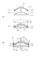
図1は、眼鏡用偏光プラスチックレンズの断面図である。図1のレンズはセミフィニッシュレンズ(以下、プラスチックレンズという)である。なお、本実施形態において、プラスチックレンズ100を処方に合わせて研磨することにより得られたレンズを完成品レンズと言う。図1(A)はベースカーブが相対的に小さい眼鏡用偏光プラスチックレンズの例、図1(B)はベースカーブが相対的に大きい眼鏡用偏光プラスチックレンズの例である。
An embodiment of the present invention will be described with reference to the drawings.
FIG. 1 is a cross-sectional view of a polarizing plastic lens for spectacles. The lens in FIG. 1 is a semi-finished lens (hereinafter referred to as a plastic lens). In the present embodiment, a lens obtained by polishing the
<レンズの構成>
図1(A)、(B)に示すように、プラスチックレンズ100は、眼鏡用のプラスチックレンズであり、第一のレンズ基材110と第二のレンズ基材120との間に、偏光フィルム14が設けられた構成である。第一のレンズ基材110は、プラスチックレンズ100の表面(物体側)に設けられ、第二のレンズ基材120は、裏面(眼球側)に設けられている。そして、第一のレンズ基材110は、偏光フィルム14に対向する面と反対側の面に物体側の面111を有し、第二のレンズ基材120は、偏光フィルム14に対向する面と反対側の面に眼球側の面121を有する。ここで、偏光フィルム14は、プラスチックレンズ100において、物体側の面111に向かって凸形状を有することが好ましい。これにより、物体側の面111の形状に沿うように偏光フィルム14を配置できるので、眼球側の面121に向かって偏光フィルムが凸形状を有する場合よりも、第二のレンズ基材120における研磨可能な厚さを大きくすることができる。
<Lens configuration>
As shown in FIGS. 1A and 1B, the
第一のレンズ基材110および第二のレンズ基材120は、屈折率が1.60以上の透明なプラスチック製であることが好ましい。第一のレンズ基材110および第二のレンズ基材120の材料としては、アクリル樹脂、チオウレタン系樹脂、チオエポキシ系樹脂、メタクリル系樹脂、アリル系樹脂、エピスルフィド系樹脂、ポリカーボネート樹脂等が例示できる。薄型化の観点から、これらの中でも、チオウレタン系樹脂およびチオエポキシ系樹脂が好ましい。なお、第一のレンズ基材110と第二のレンズ基材120とは同じ材料であることが好ましい。
The
プラスチックレンズ100の物体側の面111と偏光フィルム14との距離の最小値は0.3mm以上0.7mm以下である。物体側の面111と偏光フィルム14との距離が最小となる位置は物体側の面111の曲率(単焦点レンズにおいてはベースカーブ、単位はディオプター)と偏光フィルム14の曲率との組み合わせによって異なる。また、物体側の面111と偏光フィルム14との距離が最小となる点は1点とは限らない。例えば、物体側の面111の曲率よりも偏光フィルム14の曲率の方が大きければ、物体側の面111の頂点Tが偏光フィルム14との距離W1が最も小さい点であり、物体側の面111の曲率よりも偏光フィルム14の曲率の方が小さければ、物体側の面111の外周部が偏光フィルム14との距離W1が最も小さい点を含む。物体側の面111の曲率と偏光フィルム14の曲率とが等しい場合には、物体側の面111の全体において偏光フィルム14との距離は一定して最小であるとみなすことができる。図1(A)に示されるプラスチックレンズ100は、ベースカーブが2D(ディオプター)、偏光フィルム14の曲率が3Dで処方度数がマイナスの単焦点レンズである。図1(A)のプラスチックレンズ100においては、物体側の面111の頂点Tが偏光フィルム14との距離W1が最も小さい点であり、頂点Tと偏光フィルム14との距離が0.3mm以上0.7mm以下である。ここで、頂点Tは、セミフィニッシュレンズ(プラスチックレンズ100)を平面視でみたときの円の中心を通る垂線と物体側の面111との交点とする。あるいは、完成品レンズにおけるアイポイント(眼鏡を掛けたときの第一眼位において視線と物体側の面111とが交わる点)またはフィッティングポイントであってもよい。図1(B)に示されるプラスチックレンズ100は、ベースカーブが10D、偏光フィルム14の曲率が8Dで処方度数がプラスの単焦点レンズである。図1(B)のプラスチックレンズ100においては、物体側の面111の外周部(レンズの側面と物体側の面111とが交差する位置)が偏光フィルム14との距離W1が最も小さい領域であり、外周部と偏光フィルム14との距離が0.3mm以上0.7mm以下である。
The minimum distance between the object-
また、第一のレンズ基材110は、偏光フィルム14に対向する面とは反対側の面が物体側の面111であって、物体側の面111は球面であることが好ましい。物体側の面111を球面とすることにより、プラスチックレンズ100の製造が容易になり、汎用のモールドを用いて製造することができる。
In the
第二のレンズ基材120は、眼球側の面121が処方面である。
完成品レンズを製造するにあたっては、第二のレンズ基材120の眼球側の面121を研磨することにより、第二のレンズ基材120と偏光フィルム14との距離W2の最小値を0.3mmから0.4mm程度とする。その結果、完成品レンズの厚さWの最小値を通常の完成品レンズと同等の薄さの1.1mm以下とすることができる。ここで、通常の完成品レンズとは、偏光フィルム等のフィルムが第一のレンズ基材110と第二のレンズ基材120との間に設けられていない眼鏡用レンズを言う。また、完成品レンズの厚さが最小となる位置は、物体側の面111の曲率と偏光フィルム14の曲率との組み合わせによって異なり、1点とは限らない。例えば、物体側の面111の曲率よりも偏光フィルム14の曲率の方が大きければ、頂点Tの位置において完成品レンズの厚さWが最小となる。この場合、プラスチックレンズ100(セミフィニッシュレンズ)において物体側の面111と偏光フィルム14との距離W1が最小となる点と完成品レンズの厚さWが最小となる点は一致し、完成品レンズを平面視でみたときに物体側の面111の頂点Tを通る垂線と眼球側の面121との交点と頂点Tとを結ぶ線分の長さが完成品レンズの厚さWの最小値である。また、プラスチックレンズ100における距離W1の最小値と完成品レンズにおける距離W1の最小値は一致する。一方、物体側の面111の曲率よりも偏光フィルム14の曲率の方が小さければ、完成品レンズにおいて、物体側の面111の外周部が完成品レンズの厚さWが最小となる点を含む。この場合、プラスチックレンズ100において物体側の面111と偏光フィルム14との距離W1が最小となる点と完成品レンズの厚さWが最小となる点は必ずしも一致せず、プラスチックレンズ100における距離W1と完成品レンズにおける距離W1も等しいとは限らない。例えば、完成品レンズが玉型加工済みである場合には、完成品レンズの物体側の面111の外周部(レンズ側面と物体側の面111とが交差する位置)は、プラスチックレンズ100における物体側の面111の外周部よりも平面視において内側に位置し、完成品レンズにおける距離W1の最小値はプラスチックレンズ100における距離W1の最小値よりも大きく、0.7mm以下とは限らない。なお、物体側の面111の曲率と偏光フィルム14の曲率とが等しい場合には、物体側の面111の全体において完成品レンズの厚さWは一定して最小であるとみなすことができる。また、プラスチックレンズ100の厚さWに対して、偏光フィルム14の厚さは後述するように無視できる程度の厚さのため、便宜上、偏光フィルム14の厚みは無視している。
As for the 2nd
In manufacturing a finished lens, the minimum value of the distance W2 between the
本実施形態の偏光フィルム14は、市販のヨウ素系偏光フィルムがプレス成形、真空成形等によって所定の曲率に曲面加工が施され、外形が円形状に切り抜かれたフィルム状の基材である。偏光フィルム14の厚さは、10μm〜500μm程度が好ましい。厚さが10μm未満の場合には、剛性が弱く、取り扱いが難しくなる。また500μmを超える場合には、曲面加工を施す際に、所定の曲率が得られ難くなる。
The
偏光フィルム14に用いる偏光フィルムとしては、ポリビニルアルコール(PVA)からなる樹脂層を備える単層または多層のフィルムであることが好ましい。PVAは透明性、耐熱性、染色剤であるヨウ素または二色性染料との親和性、延伸時の配向性のいずれもが優れた材料である。
多層の偏光フィルム14は、PVAにヨウ素を含浸させものをフィルム状に成形して一軸方向に延伸した樹脂層を形成後、当該樹脂層の両面にトリアセチルセルロース(TAC)を保護層として積層することにより得られる。
なお、ヨウ素の替わりに二色性染料を用いて作製された偏光フィルムを使用することも可能である。また、単層の偏光フィルムとして、TACでの保護層を積層していないPVAや、PVAに替えてポリエチレンテレフタレート(PET)を用いた偏光フィルムを用いることもできる。本実施形態ではTACでの保護層を積層していないPVAの偏光フィルム14を用いる。
As a polarizing film used for the
The multi-layer
In addition, it is also possible to use the polarizing film produced using the dichroic dye instead of iodine. In addition, as a single-layer polarizing film, a PVA in which a protective layer of TAC is not laminated, or a polarizing film using polyethylene terephthalate (PET) instead of PVA can be used. In this embodiment, a PVA
<レンズの製造方法>
本実施形態のプラスチックレンズ100の製造方法を図面に基づいて説明する。
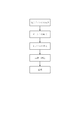
図2は、本実施形態に係るプラスチックレンズ100の製造工程を示す図である。本実施形態の製造方法は、図2に示すように大きく分けて5つの工程によって実行される。以下、工程を順に説明する。
<Lens manufacturing method>
A method for manufacturing the
FIG. 2 is a diagram illustrating a manufacturing process of the
(偏光フィルムの成形)
図3は、本実施形態に係る偏光フィルム14の成形方法を示す図である。図3(A)に示すように、一軸延伸したPVA製フィルムを長方形形状にカットした平板状のシート体10を周知のプレス手段によってプレスすることで2つの球面形状の湾曲面12が形成される。湾曲面12の曲率は製造される予定のプラスチックレンズ100(図1参照)のベースカーブ(物体側の面111の曲率)に応じて設定されている。例えば、ベースカーブが大きいほど湾曲面12の曲率を大きくしてもよい。偏光フィルム14は、プラスチックレンズ100のベースカーブと同じ曲率に形成されていてもよい。本実施形態では、ベースカーブの大きさを数段階に区分し、各段階に対して異なる曲率の湾曲面12を設定する。本実施形態では各々の湾曲面12の周囲のシート体10部分を残しながら図の破線Kに沿ってカットして偏光フィルム14を得る。
(Formation of polarizing film)
FIG. 3 is a diagram illustrating a method for forming the
偏光フィルム14の径は、図3(B)に示すように、第一のモールド(第一のレンズ基材用モールド)16及び第二のモールド(第二のレンズ基材用モールド)18の内径よりも小さいことが好ましい。例えば、本実施形態における偏光フィルム14の径は、第一のモールド16の内径より2mm程度小さい。これにより、レンズ基材のモノマーをキャビティーに注入する場合に、偏光フィルム14の両側にモノマーが回り込むようになり、キャビティー内へのモノマーの注入をスムーズに行うことができる。
As shown in FIG. 3B, the
(モールドの組立)
図4は、本実施形態に係る第一のモールド16を下方(製造されるプラスチックレンズ100の眼球側)から見た平面図である。
偏光フィルム14の成形の次に、第一のモールド16の裏面16aに接着剤20を塗布する。接着剤20は、第一のモールド16の裏面16aの周縁部である外周部に複数個所塗布される。例えば3、4箇所に塗布される。本実施形態では直交する4方向の縁取り上に4箇所塗布されている。例えば、偏光フィルム14の外周部に紫外線硬化タイプの接着剤20をディスペンサーで塗布する。
(Mold assembly)
FIG. 4 is a plan view of the
Following the formation of the
第一のモールド16は、プラスチックレンズ100の物体側の面111および眼球側の面121のうちいずれか一方の面を形成することに用いられるモールドである。本実施形態では、第一のモールド16は、プラスチックレンズ100の物体側の面111を形成することに用いられるモールドである。第一のモールド16はガラス製で、平面視において円形状である。第一のモールド16の凹面である裏面16aは成形されるプラスチックレンズ100の物体側の面111を成形するための曲面とされている。第一のモールド16は、紫外線が透過する特性を有する材料であれば、特に種類(無機物、有機物)は問わない。本実施形態では、第一のモールド16にクラウンガラスを用いる。なお、光透過性の有機物(例えば樹脂)は、紫外線の照射により劣化するため、プラスチックレンズを大量に成形するモールドには適さない。しかし、コスト安の利点を利用して、例えば少量のサンプル製品等を成型するモールドに用いてもよい。
The
本実施形態で用いる接着剤20は、紫外線硬化樹脂材である。紫外線硬化樹脂材は、周知のように紫外線の光エネルギーに反応して液体から固体に化学的に変化する特性を有する。紫外線硬化樹脂材は、プレポリマー、モノマー、光重合開始剤及び添加剤を含む合成樹脂からなる。なお、本実施形態に用いる紫外線硬化樹脂材としては、特に種類は限定しないが、モノマーの仕様に応じて適切なものを選択する。本実施形態においては、紫外線硬化性エポキシ樹脂Pを使用する。 The adhesive 20 used in the present embodiment is an ultraviolet curable resin material. As is well known, the ultraviolet curable resin material has a characteristic of chemically changing from a liquid to a solid in response to light energy of ultraviolet rays. The ultraviolet curable resin material is made of a synthetic resin containing a prepolymer, a monomer, a photopolymerization initiator, and an additive. In addition, although the kind in particular is not limited as an ultraviolet curable resin material used for this embodiment, A suitable thing is selected according to the specification of a monomer. In the present embodiment, an ultraviolet curable epoxy resin P is used.
図5は、第一のモールド16に接着剤20を塗布する方法を示す図であり、図6は、接着剤20を塗布する吐出装置を示す図である。図5及び図6に基づいて接着剤20を塗布する吐出装置22の概略を説明する。吐出装置22は図示しないモーター装置が内蔵された本体24と本体24から上方に突出する回転軸26と回転軸26の上端に配設されたターンテーブル28とを備えている。ターンテーブル28上面には第一のモールド16の表面16b周縁近傍に当接する可撓性のあるリング状の固定パッド30がセットされている(図には側面が示されている)。リング状の固定パッド30を使用するのは第一のモールド16の固定手段を表面16bの光透過面になるべく接触させないためである。本体24から上方に延出されるロッド32にはスライダー34を介してシリンジ36が装着されている。シリンジ36は図示しない本体24内のディスペンサー装置による空圧制御によって先端のニードル38から粘性のある接着剤20(紫外線硬化性エポキシ樹脂P)を一定の吐出量で吐出させる。
FIG. 5 is a view showing a method for applying the adhesive 20 to the
なお、実際には吐出装置22におけるターンテーブル28やシリンジ36は複数用意され、1台の吐出装置22で多数の第一のモールド16に接着剤20を塗布する処理が可能となっている。
In practice, a plurality of
次に吐出装置22を使用した接着剤20の塗布方法について簡単に説明する。第一のモールド16の外周部に接着剤20としてディスペンサーで塗布する。第一のモールド16を位置決めした後、第一のモールド16の外周部に接着剤を塗布する。図5及び図6に示すように、ターンテーブル28の固定パッド30上に第一のモールド16を載置し、シリンジ36の位置を適宜調整して、ニードル38を第一のモールド16の裏面16aの外周部に対向する位置に配置する。そして、吐出装置22を駆動させる。つまりターンテーブル28を回転させて第一のモールド16を周方向に回転させ、第一のモールド16における接着剤20を塗布すべき位置がニードル38の下方に到達したところで、ディスペンサー装置を駆動させてニードル38先端から裏面16aの外周部に接着剤20を吐出させる。接着剤20の高さは、接着剤20を塗布すべき位置ごとにほぼ同じ高さに形成される。また、偏光フィルム14と第一のモールド16との距離W1の最小値を0.3mm以上とするために、接着剤20の高さは0.3mm以上とする。接着剤20の高さは、偏光フィルム14と第一のモールド16との距離に応じて調節してもよい。
Next, a method for applying the adhesive 20 using the
図7及び図8は、本実施形態に係るプラスチックレンズ100の製造方法を示す図である。
まず、組み立てる第一のモールド16の中心高さ、保持された偏光フィルム14の中心の高さを計測する。偏光フィルム14の高さ測定では、偏光フィルム14は軟質であるため、非接触タイプのセンサー(例えば、キーエンスCCD透過型デジタルレーザーセンサー IGシリーズ)を用いて偏光フィルム14の頂点高さを測定する。
第一のモールド16の高さ測定では、第一のモールド16は硬質なので、接触式の測定プローブ(例えば、NikonデジマイクロMFシリーズあるいはミツトヨデジマチックインジケーター543シリーズ)で第一のモールド16の頂点高さを測定する。
次に、図7(A)に示すように、偏光フィルム14の表方向から第一のモールド16を偏光フィルム14上に載せる。あるいは、固定台51に保持された偏光フィルム14を、固定パッド52に保持された第一のモールド16に接近させる。
7 and 8 are diagrams illustrating a method for manufacturing the
First, the center height of the
In measuring the height of the
Next, as shown in FIG. 7A, the
次に、第一のモールド16と偏光フィルム14との中心高さを元に、第一のモールド16の裏面16aと偏光フィルム14との距離Hの最小値(以後、クリアランスHとも言う。)が0.3mm以上0.7mm以下となるまで近づけて偏光フィルム14に接着剤20を接触させる。その後紫外線照射装置40を駆動させて照射灯44先端から紫外線を接着剤20に照射し、接着剤20を固化させる。紫外線を照射する時間は、選択した接着剤20の種類にもよるが短時間(数秒〜数十秒)で済むため、製造サイクルへの影響を抑えることができる。例えば、500mWで15秒間紫外線を照射する。なお、紫外線照射量が不足すると判断される場合には適宜ターンテーブル28を回転させて紫外線照射装置40による紫外線の照射を、形成させた接着剤20に継続して行うことも可能である。本実施形態では、後述する加熱・硬化等によるモノマーの収縮または膨張は無視できる程度であるため、クリアランスHの最小値は物体側の面111と偏光フィルム14との距離W1の最小値に等しいとみなすことができる。なお、加熱・硬化等によってモノマー硬化品の厚さが変化する場合には、変化量を考慮してクリアランスHの最小値を設定することが好ましい。
Next, based on the center height between the
次に、設定された厚さWとなるように第二のモールド18を偏光フィルム14に対向配置させる。すなわち、第一のモールド16及び第二のモールド18で偏光フィルム14を挟むようにする。第二のモールド18はガラス製の円形板状体とされている。第二のモールド18の表面18aは成形されるプラスチックレンズ100の眼球側の面121を成形するための曲面とされている。
Next, the
次に、図7(B)に示すように、一対の第一のモールド16及び第二のモールド18を、プラスチックレンズ100の成形に必要な間隔をとって保持し、2枚の第一及び第二のモールド16,18の側面に、片面に接着剤層を有する粘着テープ(間隔保持用部材)46を1周より少し多く巻き付ける。この際、第一のモールド16及び第二のモールド18は、固定パッド52にセットされている。固定パッド52は、図示しないモーター装置から突出する回転軸54により回転駆動される。
Next, as shown in FIG. 7B, the pair of the
粘着テープ46の材質は特に限定されない。なお、使いやすさや経済性等の観点から、プラスチックの粘着テープを使用することが好ましい。例えば、粘着テープの基材としてはポリプロピレン製のものとポリエチレンテレフタレート製のものを、粘着剤としてはアクリル系、天然ゴム系、シリコン系のものを各々組み合わせて用意する。なお、粘着テープ46には、モノマーを注入するための注入孔(図示せず)を設けても良い。
The material of the
偏光フィルム14を介在させて組み立てられた第一のモールド16及び第二のモールド18と粘着テープ46との状態を母型48とする。
The state of the
(モノマーの注入)
次に、図8に示すように、組み立てられた母型48に対して調合されたモノマーを注入孔より注入器を用いて、一対の第一のモールド16及び第二のモールド18と粘着テープ46とで形成されたキャビティー50内に、キャビティー50内に気泡が残らないようにモノマーを充填する。
(Monomer injection)
Next, as shown in FIG. 8, a pair of
(加熱・硬化)
その後、モノマーを充填した母型48を加熱炉に入れて加熱する。ここで、加熱温度は、好ましくは0〜150℃、より好ましくは10〜130℃であり、好ましくは5〜50時間、より好ましくは10〜25時間かけて昇温し、重合を行う。例えば、30℃で7時間保持し、その後30〜120℃まで10時間かけて昇温する。
(Heating / curing)
Thereafter, the
(脱型)
加熱処理が終了すると、モノマーが固化して母型48内に偏光フィルム14が内蔵されたモノマー硬化品が成形される。母型48を加熱炉より取り出し、粘着テープ46を剥離し、第一のモールド16及び第二のモールド18とモノマー硬化品とを分離させて図1に示すプラスチックレンズ100(セミフィニッシュレンズ)を得る。なお、本実施形態におけるプラスチックレンズ100の厚さWの最小値は5mmである。
(Demolding)
When the heat treatment is completed, the monomer is solidified, and a cured monomer product in which the
(研磨加工)
その後、プラスチックレンズ100の眼球側の面121を研磨加工して、第二のレンズ基材120と偏光フィルム14との距離W2の最小値を0.3mmから0.4mm程度とすることで、厚さWの最小値が1.1mm以下の完成品レンズを得る。
(Polishing)
Then, the
(表面処理)
上記研磨加工後の完成品レンズには、さらに通常のプライマー、ハードコート、および反射防止膜の塗布や、撥水撥油処理をおこなってもよい。
(surface treatment)
The finished lens after the polishing may be further subjected to normal primer, hard coat, and antireflection coating, and water / oil repellent treatment.
本実施形態によれば、クリアランスHの最小値を0.3mm以上0.7mm以下に設定したので、物体側の面111と偏光フィルム14との距離W1の最小値が0.3mm以上0.7mm以下であるプラスチックレンズ100が得られる。プラスチックレンズ100において、第二のレンズ基材120の眼球側の面121を研磨すれば、完成品レンズの厚さWの最小値を1.1mm以下とすることができ、通常の完成品レンズと同等に薄型化された完成品レンズを提供できる。
According to the present embodiment, since the minimum value of the clearance H is set to 0.3 mm or more and 0.7 mm or less, the minimum value of the distance W1 between the object-
さらに、第一のレンズ基材110の物体側の面111を球面としたので、製造が容易であり、汎用のモールドを用いることができる。
また、第一のレンズ基材110および第二のレンズ基材120の屈折率を1.60とすることで、プラスチックレンズ100をより薄型化できる。例えば、処方度数の絶対値が大きい(強度の処方の)レンズにおいては、高屈折率の基材を使用すれば、より弱い度数のレンズと同等の厚さとすることができる。
また、偏光フィルム14としてPVAを用いたので、簡易に眼鏡用偏光プラスチックレンズを提供することができる。
Furthermore, since the object-
Moreover, the
Moreover, since PVA was used as the
なお、本発明は、次のように変更して具体化することも可能である。
上記実施形態では接着剤20を、光硬化性樹脂を使用して紫外線を照射することで固化させていたが、熱硬化性樹脂を使用して加熱によって固化させてもよい。
It should be noted that the present invention can be embodied with the following modifications.
In the said embodiment, although the
上記実施形態では第一のモールド16を回転させて接着剤20を塗布するようにしていたが、シリンジ36側が移動して接着剤20を塗布する構成であっても構わない。
In the above embodiment, the
上記実施形態で接着剤20を塗布する対象は、第一のモールド16に限らず、偏光フィルム14に塗布してもよい。また、第一のモールド16と偏光フィルム14とを近接させる場合、偏光フィルム14のみを移動させるだけでなく、第一のモールド16を移動させる方法や第一のモールド16と偏光フィルム14との両方を移動させて近接させてもよい。また、第二のモールド18(眼球側の面を形成するためのモールド)に接着剤20を塗布しても良い。この場合は、クリアランスHの最小値が0.3mm以上0.7mm以下となる高さまで接着剤を塗布する。例えば、第一のモールド16と第二のモールド18との間隔の最小値とクリアランスHの最小値との差を、接着剤の高さとしてもよい。
The object to which the adhesive 20 is applied in the above embodiment is not limited to the
上記実施形態では球面形状に湾曲した偏光フィルム14を例として挙げたが、平板な偏光フィルム14を使用してもよい。また、偏光フィルム14は必ずしも周囲が円形形状に構成されていなくともよい。
In the said embodiment, although the
上記実施形態の偏光フィルム14の材質は上記に限定されるものではない。上記実施形態では単層のPVAを用いたが、PVAからなる樹脂層の両面をトリアセチルセルロースからなる保護層で挟んだフィルム(TPT)を用いてもよい。また、保護層は片面だけでもよい。
The material of the
上記実施形態の吐出装置22の構成は一例であって他の構成で実現したその他の接着剤20を塗布させる手段に適宜変更することは自由である。
また、第一のモールド16および第二のモールド18の形状は、上記実施形態で用いた形状に限らない。また、完成品レンズは単焦点レンズであっても、累進屈折力レンズであっても良い。
The configuration of the
Moreover, the shape of the
次に実施例について説明する。
まず、実施例に用いたモノマーの調合について、以下に説明する。
(モノマーの調合)
(1)1.60チオウレタン(屈折率が1.60のチオウレタンのモノマー)
プラスチックレンズ原料として、ノルボルネンジイソシアネートを50g、ペンタエリスリトールテトラキス(3−メルカプトプロピオネート)を主成分とするポリチオール化合物を24g、4−メルカプトメチル−3,6−ジチア−1,8−オクタンジチオールを主成分とするポリチオール化合物を26gを混合し、十分に撹拌を行った。
Next, examples will be described.
First, preparation of the monomers used in the examples will be described below.
(Monomer preparation)
(1) 1.60 thiourethane (a thiourethane monomer having a refractive index of 1.60)
As raw materials for plastic lenses, 50 g of norbornene diisocyanate, 24 g of polythiol compound mainly composed of pentaerythritol tetrakis (3-mercaptopropionate), mainly 4-mercaptomethyl-3,6-dithia-1,8-octanedithiol 26 g of the polythiol compound as a component was mixed and sufficiently stirred.
そこに紫外線吸収剤として商標名「SEESORB709」(シプロ化成工業製)を2.5g、内部離型剤として商標名「MR用内部離型剤」(三井化学社製)を0.1g添加し、混合した後、十分に撹拌して、完全に分散または溶解させたプラスチックレンズ原料中に、触媒としてジブチル錫ジクロライドを250ppm添加し、室温で十分に撹拌して均一な液体の組成物とした。ついで組成物を5mmHgに減圧して攪拌しながら30分間脱気を行った。 2.5 g of the trade name “SEESORB709” (manufactured by Sipro Kasei Kogyo Co., Ltd.) is added as an ultraviolet absorber, and 0.1 g of the trade name “internal mold release agent for MR” (manufactured by Mitsui Chemicals) is added as an internal mold release agent. After mixing, 250 ppm of dibutyltin dichloride was added as a catalyst to the plastic lens raw material which was sufficiently stirred and completely dispersed or dissolved, and stirred sufficiently at room temperature to obtain a uniform liquid composition. Next, the composition was degassed for 30 minutes while reducing the pressure to 5 mmHg and stirring.
(2)1.67チオウレタン(屈折率が1.67のチオウレタン基材のモノマー)
プラスチックレンズ原料として、m−キシレンジイソシアネートを50.6g、4,8−ジメルカプトメチル−1,11−ジメルカプト−3,6,9−トリチアウンデカン49.4gを混合し、十分に撹拌を行った。なお、4,8−ジメルカプトメチル−1,11−ジメルカプト−3,6,9−トリチアウンデカンに代えて、4,7−ジメルカプトメチル−1,11−ジメルカプト−3,6,9−トリチアウンデカン或いは5,7−ジメルカプトメチル−1,11−ジメルカプト−3,6,9−トリチアウンデカンを用いても良い。
(2) 1.67 thiourethane (a thiourethane base monomer having a refractive index of 1.67)
As a plastic lens raw material, 50.6 g of m-xylene diisocyanate and 49.4 g of 4,8-dimercaptomethyl-1,11-dimercapto-3,6,9-trithiaundecane were mixed and sufficiently stirred. . In place of 4,8-dimercaptomethyl-1,11-dimercapto-3,6,9-trithiaundecane, 4,7-dimercaptomethyl-1,11-dimercapto-3,6,9-tri Thiaundecane or 5,7-dimercaptomethyl-1,11-dimercapto-3,6,9-trithiaundecane may be used.
そこに紫外線吸収剤として商標名「SEESORB701」(シプロ化成工業製)を1.2g、内部離型剤として商標名「MR用内部離型剤」(三井化学社製)を0.1g添加し、混合した後、十分に撹拌して、完全に分散または溶解させたプラスチックレンズ原料中に、触媒としてジブチル錫ジクロライドを100ppm添加し、室温で十分に撹拌して均一液とした。
ついで、組成物を5mmHgに減圧して攪拌しながら30分間脱気を行った。
1.2 g of the trade name “SEESORB701” (manufactured by Sipro Kasei Kogyo Co., Ltd.) is added as an ultraviolet absorber, and 0.1 g of the trade name “internal mold release agent for MR” (manufactured by Mitsui Chemicals) is added as an internal mold release agent. After mixing, 100 ppm of dibutyltin dichloride as a catalyst was added to the plastic lens raw material which was sufficiently stirred and completely dispersed or dissolved, and stirred sufficiently at room temperature to obtain a uniform solution.
Next, the composition was degassed for 30 minutes while reducing the pressure to 5 mmHg and stirring.
(3)1.74チオエポキシ(屈折率が1.74のチオエポキシ基材のモノマー)
プラスチックレンズ原料として、ビス−(2,3エピチオプロピル)ジスルフィドを90.0g、4,8−ジメルカプトメチル−1,11−ジメルカプト−3,6,9−トリチアウンデカン10.0gを混合し、十分に撹拌を行った。なお、ビス−(2,3エピチオプロピル)ジスルフィドを90.0g、4,8−ジメルカプトメチル−1,11−ジメルカプト−3,6,9−トリチアウンデカンに代えて、4,7−ジメルカプトメチル−1,11−ジメルカプト−3,6,9−トリチアウンデカン或いは5,7−ジメルカプトメチル−1,11−ジメルカプト−3,6,9−トリチアウンデカンを用いても良い。
(3) 1.74 thioepoxy (a thioepoxy base monomer having a refractive index of 1.74)
As a plastic lens raw material, 90.0 g of bis- (2,3 epithiopropyl) disulfide and 10.0 g of 4,8-dimercaptomethyl-1,11-dimercapto-3,6,9-trithiaundecane are mixed. Stir well. In addition, instead of 90.0 g of bis- (2,3 epithiopropyl) disulfide and 4,8-dimercaptomethyl-1,11-dimercapto-3,6,9-trithiaundecane, Mercaptomethyl-1,11-dimercapto-3,6,9-trithiaundecane or 5,7-dimercaptomethyl-1,11-dimercapto-3,6,9-trithiaundecane may be used.
そこに紫外線吸収剤として商標名「SEESORB701」(シプロ化成工業製)を1.2g添加し、十分に撹拌して、完全に溶解させた。その後、触媒としてN,N−ジメチルシクロヘキシルアミンを0.10g混合し、室温で十分に撹拌して均一液とした。
ついで、組成物を5mmHgに減圧して攪拌しながら30分間脱気を行った。
1.2 g of a trade name “SEESORB701” (manufactured by Sipro Kasei Kogyo Co., Ltd.) was added as an ultraviolet absorber, and the mixture was sufficiently stirred to dissolve completely. Thereafter, 0.10 g of N, N-dimethylcyclohexylamine as a catalyst was mixed and sufficiently stirred at room temperature to obtain a uniform liquid.
Next, the composition was degassed for 30 minutes while reducing the pressure to 5 mmHg and stirring.
表1に、実施例1〜12および比較例1〜5の詳細を示した。表1において、モノマーは上記「モノマーの調合」で得られたモノマーである。Hはクリアランスの最小値(以下単にクリアランスHという)、W1はプラスチックレンズ(セミフィニッシュレンズ)の眼球側の面と偏光フィルムとの距離の最小値(以下単に距離W1という)、Wは完成品レンズの厚さの最小値(以下単に厚さWという)である。SFはセミフィニッシュの略である。本実施例においては、クリアランスが最小となる位置は、ベースカーブが6D未満の場合にはセミフィニッシュレンズの中心部(頂点Tの位置)、ベースカーブが6D以上ではセミフィニッシュレンズの外周部であったので、それぞれの例においては、当該位置においてクリアランスHを設定した。作成されたプラスチックレンズにおいて、眼球側の面と偏光フィルムとの距離が最小となった位置は、クリアランスHを設定したのと同じ位置であった。各実施例および比較例において、10個のレンズを作成した。なお、一部の実施例において、レンズのベースカーブに応じて偏光フィルムの曲率を変更しているが、全ての例において同じ曲率の偏光フィルムを使用することも可能である。 Table 1 shows details of Examples 1 to 12 and Comparative Examples 1 to 5. In Table 1, a monomer is a monomer obtained by the above-mentioned “preparation of monomer”. H is the minimum clearance (hereinafter simply referred to as clearance H), W1 is the minimum distance between the eyeball side surface of the plastic lens (semi-finished lens) and the polarizing film (hereinafter simply referred to as distance W1), and W is the finished product lens. Is the minimum value (hereinafter simply referred to as thickness W). SF is an abbreviation for semi-finish. In the present embodiment, the position where the clearance is minimum is the center of the semi-finished lens (the position of the apex T) when the base curve is less than 6D, and the outer periphery of the semi-finished lens when the base curve is 6D or more. Therefore, in each example, the clearance H is set at the position. In the produced plastic lens, the position where the distance between the eyeball side surface and the polarizing film was minimized was the same position where the clearance H was set. In each example and comparative example, 10 lenses were prepared. In some embodiments, the curvature of the polarizing film is changed according to the base curve of the lens. However, it is also possible to use a polarizing film having the same curvature in all examples.
(実施例1)
モノマーの調合で得られた1.60チオウレタンのモノマーを用いて、実施形態に記載の方法でプラスチックレンズ100を得た。次いで、得られたプラスチックレンズ100に、上記研磨加工および表面処理を施し、完成品レンズを得た。
Example 1
A
(実施例2)
実施例1において、クリアランスHの最小値を表1に記載の値とした以外は、実施例1と同様にして完成品レンズを得た。
(Example 2)
A finished product lens was obtained in the same manner as in Example 1 except that the minimum value of the clearance H in Example 1 was changed to the value shown in Table 1.
(実施例3〜4)
実施例1において、モノマーを表1に記載の材料に変更した以外は、実施例1と同様にして完成品レンズを得た。
(Examples 3 to 4)
A finished lens was obtained in the same manner as in Example 1 except that the monomer was changed to the material shown in Table 1 in Example 1.
(実施例5〜6)
実施例1において、偏光フィルムを表1に記載の材料に変更した以外は、実施例1と同様にして完成品レンズを得た。
(Examples 5-6)
In Example 1, a finished lens was obtained in the same manner as in Example 1 except that the polarizing film was changed to the materials shown in Table 1.
(実施例7)
実施例1において、レンズのベースカーブを表1に記載の値とした以外は、実施例1と同様にして完成品レンズを得た。
(Example 7)
A finished product lens was obtained in the same manner as in Example 1 except that the base curve of the lens was changed to the values shown in Table 1.
(実施例8)
実施例2において、レンズのベースカーブを表1に記載の値とした以外は、実施例1と同様にして完成品レンズを得た。
(Example 8)
In Example 2, a finished lens was obtained in the same manner as in Example 1 except that the base curve of the lens was changed to the value shown in Table 1.
(実施例9〜10、12)
実施例1において、レンズのベースカーブおよび偏光フィルムの曲率を表1に記載の値とした以外は、実施例1と同様にして完成品レンズを得た。
(Examples 9 to 10 and 12)
A finished product lens was obtained in the same manner as in Example 1 except that the base curve of the lens and the curvature of the polarizing film were changed to the values shown in Table 1.
(実施例11)
実施例2において、レンズのベースカーブおよび偏光フィルムの曲率を表1に記載の値とした以外は、実施例1と同様にして完成品レンズを得た。
(Example 11)
In Example 2, a finished lens was obtained in the same manner as in Example 1 except that the base curve of the lens and the curvature of the polarizing film were set to the values shown in Table 1.
(比較例1〜2)
実施例7または実施例8において、クリアランスHの最小値を表1に記載の値とした以外は、実施例1と同様にして作業を行った。
(Comparative Examples 1-2)
In Example 7 or Example 8, the operation was performed in the same manner as in Example 1 except that the minimum value of the clearance H was changed to the value shown in Table 1.
(比較例3〜4)
実施例10または実施例11において、クリアランスHの最小値を表1に記載の値とした以外は、実施例1と同様にして作業を行った。
(Comparative Examples 3-4)
In Example 10 or Example 11, the operation was performed in the same manner as in Example 1 except that the minimum value of clearance H was set to the value shown in Table 1.
(比較例5)
実施例1において、接着剤に偏光フィルムを接着させることでクリアランスHの最小値を決定する代わりに、ガスケットに設けられた挿入溝に偏光フィルムを挿し込んで保持した以外は実施例1と同様にして完成品レンズを得た。
(Comparative Example 5)
In Example 1, instead of determining the minimum value of clearance H by adhering the polarizing film to the adhesive, the same as in Example 1 except that the polarizing film was inserted and held in the insertion groove provided in the gasket. And finished product lens.

実施例1〜2において、クリアランスHを0.3mm以上0.7mm以下としたところ、距離W1が0.3mm以上0.7mm以下であるプラスチックレンズが得られた。そして、プラスチックレンズの第二のレンズ基材を研磨することにより偏光フィルムを傷つけることなく、いずれも厚さWが1.1mmの完成品レンズが得られた。モノマーを変更した実施例3〜4、偏光フィルムの材料を変更した実施例5〜6、レンズのベースカーブを変更した実施例7〜12においても、同様に厚さWが1.1mmの完成品レンズが得られた。ここで、距離W1が0.3mmのプラスチックレンズ(実施例2および8)は厚さWが0.6mmから0.7mm程度まで研磨可能であるが、厚さWを1.1mm未満とすると完成品レンズの強度が不足する場合があるため、1.1mmで研磨を終了している。
これに対して、比較例1および比較例3では、クリアランスHを0.2mmとしたため、モノマーの注入工程において、第一のモールドと偏光フィルムとの間にモノマーを均一に流れこませることができず、プラスチックレンズおよび完成品レンズを製造することができなかった。また、比較例2および比較例4では、クリアランスHを0.8mmとしたため、処方面の研磨加工の限界により、完成品レンズの厚さW1が1.2mmとなり、通常の完成品レンズよりも厚くなった。比較例5では、プラスチックレンズをガスケットを用いて製造したので、偏光フィルムの曲面精度のばらつきを吸収することが困難であり、製造した10個のプラスチックレンズの間で距離W1に0.5mmから1.2mmの範囲でばらつきが生じた。その結果、偏光フィルムを傷つけてしまう可能性があるため、第二のレンズ基材を厚さWが0.3mmから0.4mmとなるまで研磨することができず、完成品レンズの厚さWは1.6mmと通常の完成品レンズよりも厚くなった。
In Examples 1 and 2, when the clearance H was set to 0.3 mm to 0.7 mm, a plastic lens having a distance W1 of 0.3 mm to 0.7 mm was obtained. Then, the finished lens having a thickness W of 1.1 mm was obtained without damaging the polarizing film by polishing the second lens substrate of the plastic lens. Similarly, in Examples 3 to 4 in which the monomer was changed, Examples 5 to 6 in which the material of the polarizing film was changed, and Examples 7 to 12 in which the base curve of the lens was changed, a finished product having a thickness W of 1.1 mm was also obtained. A lens was obtained. Here, the plastic lens having the distance W1 of 0.3 mm (Examples 2 and 8) can be polished from a thickness W of about 0.6 mm to about 0.7 mm, but is completed when the thickness W is less than 1.1 mm. Since the strength of the product lens may be insufficient, the polishing is finished at 1.1 mm.
On the other hand, in Comparative Example 1 and Comparative Example 3, since the clearance H is 0.2 mm, the monomer can flow uniformly between the first mold and the polarizing film in the monomer injection step. Therefore, plastic lenses and finished lenses could not be manufactured. In Comparative Example 2 and Comparative Example 4, since the clearance H is set to 0.8 mm, the thickness W1 of the finished product lens is 1.2 mm due to the limit of the polishing process on the prescription surface, which is thicker than a normal finished product lens. became. In Comparative Example 5, since the plastic lens was manufactured using the gasket, it is difficult to absorb the variation in the curved surface accuracy of the polarizing film, and the distance between the 10 manufactured plastic lenses is 0.5 mm to 1 mm. Variation occurred in the range of 2 mm. As a result, the polarizing film may be damaged, and the second lens substrate cannot be polished until the thickness W becomes 0.3 mm to 0.4 mm. Is 1.6 mm, which is thicker than a normal finished product lens.
14…偏光フィルム、16…第一のモールド(第一のレンズ基材用モールド)、16a…裏面(凹面)、18…第二のモールド(第二のレンズ基材用モールド)、100…プラスチックレンズ(眼鏡用偏光プラスチックレンズ)、110…第一のレンズ基材、111…物体側の面、120…第二のレンズ基材、121…眼球側の面(処方面)、T…頂点
DESCRIPTION OF
Claims (2)
前記偏光フィルムを挟んで前記第一のレンズ基材用モールドと反対側に第二のレンズ基材用モールドを配置することと、
前記第一のレンズ基材用モールドと前記偏光フィルムとの間、および、前記偏光フィルムと前記第二のレンズ基材用モールドとの間にプラスチック原料組成物を注入して、第一のレンズ基材および第二のレンズ基材を形成することと、
を含み、
前記第一のレンズ基材用モールドの周縁部の一部と偏光フィルムの周縁部の一部とを複数箇所にて接着させ、前記第一のレンズ基材用モールドと前記偏光フィルムとの間のキャビティーと、前記第二のレンズ基材用モールドと前記偏光フィルムとの間のキャビティーとを連通させた上で、前記プラスチック原料組成物を注入する、眼鏡用偏光プラスチックレンズの製造方法。 At least the peripheral portion of the first lens substrate mold so that the minimum distance from the concave surface of the first lens substrate mold on which the concave surface is formed is 0.3 mm or more and 0.7 mm or less. Adhering a part and at least a part of the peripheral edge of the polarizing film;
Placing the second lens substrate mold on the opposite side of the first lens substrate mold across the polarizing film;
A plastic raw material composition is injected between the first lens base mold and the polarizing film, and between the polarizing film and the second lens base mold, and the first lens base Forming a material and a second lens substrate;
Including
Adhering a part of the peripheral part of the mold for the first lens substrate and a part of the peripheral part of the polarizing film at a plurality of locations, between the mold for the first lens base material and the polarizing film A method for producing a polarizing plastic lens for spectacles, wherein the plastic raw material composition is injected after communicating a cavity and a cavity between the second lens substrate mold and the polarizing film.
Priority Applications (5)
| Application Number | Priority Date | Filing Date | Title |
|---|---|---|---|
| JP2012024252A JP6110595B2 (en) | 2012-02-07 | 2012-02-07 | Manufacturing method of polarizing plastic lens for spectacles |
| US14/377,351 US9782941B2 (en) | 2012-02-07 | 2013-01-25 | Polarized plastic lens for spectacles and method for manufacturing polarized plastic lens for spectacles |
| EP13746050.7A EP2813883B1 (en) | 2012-02-07 | 2013-01-25 | Polarized plastic lens for glasses and method for manufacturing polarized plastics lens for glasses |
| PCT/JP2013/000404 WO2013118444A1 (en) | 2012-02-07 | 2013-01-25 | Polarized plastic lens for glasses and method for manufacturing polarized plastics lens for glasses |
| CN201380008229.3A CN104105997B (en) | 2012-02-07 | 2013-01-25 | The glasses manufacture method of polarization glass lens and glasses polarization glass lens |
Applications Claiming Priority (1)
| Application Number | Priority Date | Filing Date | Title |
|---|---|---|---|
| JP2012024252A JP6110595B2 (en) | 2012-02-07 | 2012-02-07 | Manufacturing method of polarizing plastic lens for spectacles |
Publications (3)
| Publication Number | Publication Date |
|---|---|
| JP2013160994A JP2013160994A (en) | 2013-08-19 |
| JP2013160994A5 JP2013160994A5 (en) | 2015-03-19 |
| JP6110595B2 true JP6110595B2 (en) | 2017-04-05 |
Family
ID=48947222
Family Applications (1)
| Application Number | Title | Priority Date | Filing Date |
|---|---|---|---|
| JP2012024252A Active JP6110595B2 (en) | 2012-02-07 | 2012-02-07 | Manufacturing method of polarizing plastic lens for spectacles |
Country Status (5)
| Country | Link |
|---|---|
| US (1) | US9782941B2 (en) |
| EP (1) | EP2813883B1 (en) |
| JP (1) | JP6110595B2 (en) |
| CN (1) | CN104105997B (en) |
| WO (1) | WO2013118444A1 (en) |
Families Citing this family (19)
| Publication number | Priority date | Publication date | Assignee | Title |
|---|---|---|---|---|
| WO2014077339A1 (en) * | 2012-11-14 | 2014-05-22 | ホーヤ レンズ マニュファクチャリング フィリピン インク | Method for manufacturing polarizing plastic lens |
| ITPD20130209A1 (en) * | 2013-07-26 | 2015-01-27 | Safilo Spa | METHOD OF MANUFACTURING A POLARIZED LENS FOR GLASSES AND LENSES MADE WITH A CALLED METHOD |
| US9977262B2 (en) * | 2014-03-12 | 2018-05-22 | Honeywell International, Inc. | Electrochromic lenses and methods of fabricating the same |
| KR101625484B1 (en) * | 2015-05-18 | 2016-05-30 | 조정애 | Manufacturing Method of Polarizing Lens and Polarizing Lens made thereby |
| CN105204184B (en) * | 2015-10-12 | 2018-02-27 | 欧阳诚 | A kind of preparation method of safety glass resin polaroid glasses |
| CN105527727A (en) * | 2016-02-16 | 2016-04-27 | 侯绪华 | Plastic polarized glasses |
| EP3521867B1 (en) * | 2016-09-28 | 2022-10-12 | Mitsubishi Gas Chemical Company, Inc. | Optical lens |
| CN108908822A (en) * | 2018-06-21 | 2018-11-30 | 王中安 | A kind of manufacturing method of myopia polarized resin spectacle lens |
| US11962928B2 (en) | 2018-12-17 | 2024-04-16 | Meta Platforms Technologies, Llc | Programmable pixel array |
| US11888002B2 (en) | 2018-12-17 | 2024-01-30 | Meta Platforms Technologies, Llc | Dynamically programmable image sensor |
| US11850811B1 (en) * | 2019-06-18 | 2023-12-26 | Meta Platforms Technologies, Llc | Monolithic compound lens |
| JP7232927B2 (en) * | 2019-09-25 | 2023-03-03 | ホヤ レンズ タイランド リミテッド | Spectacle lens and manufacturing method thereof |
| JP7350588B2 (en) | 2019-09-26 | 2023-09-26 | ホヤ レンズ タイランド リミテッド | ophthalmic lenses |
| US11935291B2 (en) | 2019-10-30 | 2024-03-19 | Meta Platforms Technologies, Llc | Distributed sensor system |
| US11948089B2 (en) | 2019-11-07 | 2024-04-02 | Meta Platforms Technologies, Llc | Sparse image sensing and processing |
| US11458699B2 (en) * | 2019-12-09 | 2022-10-04 | Meta Platforms Technologies, Llc | Fabricating a lens assembly |
| US11825228B2 (en) | 2020-05-20 | 2023-11-21 | Meta Platforms Technologies, Llc | Programmable pixel array having multiple power domains |
| JP2022136683A (en) | 2021-03-08 | 2022-09-21 | ホヤ レンズ タイランド リミテッド | Polarizing lens for spectacles, method for manufacturing polarizing lens for spectacles, method for manufacturing spectacles with frame, and method for inspecting polarizing lens for spectacles |
| EP4197762A1 (en) * | 2021-12-16 | 2023-06-21 | Essilor International | Process and device for making a mold assembly suitable for molding an ophthalmic lens |
Family Cites Families (18)
| Publication number | Priority date | Publication date | Assignee | Title |
|---|---|---|---|---|
| US4090830A (en) | 1974-07-03 | 1978-05-23 | American Optical Corporation | Mold for producing polarizing optical devices |
| JPS63184816A (en) * | 1987-01-28 | 1988-07-30 | Hitachi Ltd | Key depression detecting circuit |
| JP3481183B2 (en) | 2000-05-02 | 2003-12-22 | タレックス光学工業株式会社 | Plastic polarized lens and manufacturing method thereof |
| US7077985B2 (en) * | 2000-05-30 | 2006-07-18 | Vision-Ease Lens | Injection molding of lens |
| JP2003154555A (en) * | 2001-11-20 | 2003-05-27 | Dainippon Printing Co Ltd | Manufacturing method for reflection-preventing article by injection-molding |
| FR2847198B1 (en) * | 2002-11-18 | 2006-07-28 | Marc Delery | METHOD FOR MANUFACTURING A CORRECTIVE GLASS AND PALLET GLASS FOR REALIZING A CORRECTIVE GLASS GLASS |
| JP2005067186A (en) * | 2003-08-20 | 2005-03-17 | Hanii Optical Co Ltd | Method for manufacturing polarizing lens, structure of gasket mold used therefor and polarizing lens manufactured by using these |
| FR2897693B1 (en) * | 2006-02-23 | 2008-11-21 | Essilor Int | POLARIZING OPTICAL ELEMENT COMPRISING A POLARIZER FILM AND METHOD OF FARBINATING SUCH A ELEMENT |
| JP5045148B2 (en) | 2006-04-27 | 2012-10-10 | セイコーエプソン株式会社 | Plastic polarizing lens |
| CN101058232A (en) * | 2007-05-23 | 2007-10-24 | 上海康耐特光学有限公司 | Method for manufacturing super slight type polarizing optical resin lens |
| JP5166785B2 (en) | 2007-06-25 | 2013-03-21 | 株式会社 サンルックス | Manufacturing method of polarizing plastic lens |
| AU2008304553B2 (en) * | 2007-09-24 | 2013-02-14 | Qspex Technologies, Inc. | Method for manufacturing polarized ophthalmic lenses |
| EP2244111B1 (en) * | 2008-02-07 | 2019-05-15 | Mitsui Chemicals, Inc. | Plastic polarizing lens and method for producing the same |
| JP2010039220A (en) * | 2008-08-05 | 2010-02-18 | Miyoshi Industrial Enterprise Inc | Polarizing lens and method of manufacturing method therefor |
| CN101726764A (en) * | 2008-10-17 | 2010-06-09 | 金泰德 | Polarized lens and method for manufacturing same |
| WO2010073625A1 (en) * | 2008-12-22 | 2010-07-01 | 株式会社ニコン・エシロール | Method of manufacturing resin lens, mold for manufacturing resin lens, and film for resin lens insertion |
| JP5331874B2 (en) * | 2009-03-31 | 2013-10-30 | Hoya株式会社 | Manufacturing method of progressive-power spectacle lens |
| JP5616642B2 (en) * | 2010-01-15 | 2014-10-29 | 伊藤光学工業株式会社 | Manufacturing method of polarizing element |
-
2012
- 2012-02-07 JP JP2012024252A patent/JP6110595B2/en active Active
-
2013
- 2013-01-25 CN CN201380008229.3A patent/CN104105997B/en active Active
- 2013-01-25 EP EP13746050.7A patent/EP2813883B1/en active Active
- 2013-01-25 WO PCT/JP2013/000404 patent/WO2013118444A1/en active Application Filing
- 2013-01-25 US US14/377,351 patent/US9782941B2/en active Active
Also Published As
| Publication number | Publication date |
|---|---|
| EP2813883A4 (en) | 2015-10-14 |
| EP2813883B1 (en) | 2020-08-19 |
| US20150158259A1 (en) | 2015-06-11 |
| CN104105997B (en) | 2016-07-20 |
| US9782941B2 (en) | 2017-10-10 |
| CN104105997A (en) | 2014-10-15 |
| JP2013160994A (en) | 2013-08-19 |
| EP2813883A1 (en) | 2014-12-17 |
| WO2013118444A1 (en) | 2013-08-15 |
Similar Documents
| Publication | Publication Date | Title |
|---|---|---|
| JP6110595B2 (en) | Manufacturing method of polarizing plastic lens for spectacles | |
| JP6316184B2 (en) | Manufacturing method of polarizing lens | |
| JP5851627B2 (en) | Manufacturing method of polarizing plastic lens | |
| KR100510226B1 (en) | Precision Composite Article | |
| JP6085310B2 (en) | Manufacturing method of polarizing plastic lens | |
| JP2012198390A (en) | Method of manufacturing eyeglass polarizing plastic lens | |
| WO2010073625A1 (en) | Method of manufacturing resin lens, mold for manufacturing resin lens, and film for resin lens insertion | |
| JP2014142440A (en) | Method of manufacturing polarizing lens | |
| JP2012198389A (en) | Method of manufacturing eyeglass polarizing plastic lens | |
| JPS6226289B2 (en) | ||
| JP6150461B2 (en) | Manufacturing method of polarizing lens for spectacles | |
| JP2016035597A (en) | Method for manufacturing polarizing plastic lens for spectacle | |
| JP2022533289A (en) | Manufacturing method of high refraction polarizing lens | |
| JPS61235113A (en) | Manufacture of composite plastic | |
| US20220283448A1 (en) | Polarized lens for spectacles, method for manufacturing polarized lens for spectacles, method for manufacturing framed spectacle, and method for inspecting polarized lens for spectacles | |
| JP2010120324A (en) | Method for manufacturing plastic lens | |
| JPS61213114A (en) | Manufacture of composite plastics | |
| KR20180088702A (en) | Method of manufacturing lens mold, method of manufacturing spectacle lens, and spectacle lens | |
| JP2012006190A (en) | Mold for molding plastic lens and method for producing plastic lens | |
| JP2002120232A (en) | Method for molding plastic lens | |
| JP2011245830A (en) | Mold for molding plastic lens and method for manufacturing plastic lens | |
| JP2010264621A (en) | Method for producing plastic lens |
Legal Events
| Date | Code | Title | Description |
|---|---|---|---|
| A521 | Request for written amendment filed |
Free format text: JAPANESE INTERMEDIATE CODE: A523 Effective date: 20150128 |
|
| A621 | Written request for application examination |
Free format text: JAPANESE INTERMEDIATE CODE: A621 Effective date: 20150128 |
|
| A131 | Notification of reasons for refusal |
Free format text: JAPANESE INTERMEDIATE CODE: A131 Effective date: 20160127 |
|
| A601 | Written request for extension of time |
Free format text: JAPANESE INTERMEDIATE CODE: A601 Effective date: 20160427 |
|
| A601 | Written request for extension of time |
Free format text: JAPANESE INTERMEDIATE CODE: A601 Effective date: 20160627 |
|
| A521 | Request for written amendment filed |
Free format text: JAPANESE INTERMEDIATE CODE: A523 Effective date: 20160721 |
|
| A02 | Decision of refusal |
Free format text: JAPANESE INTERMEDIATE CODE: A02 Effective date: 20160824 |
|
| A521 | Request for written amendment filed |
Free format text: JAPANESE INTERMEDIATE CODE: A523 Effective date: 20161216 |
|
| A911 | Transfer to examiner for re-examination before appeal (zenchi) |
Free format text: JAPANESE INTERMEDIATE CODE: A911 Effective date: 20161226 |
|
| TRDD | Decision of grant or rejection written | ||
| A01 | Written decision to grant a patent or to grant a registration (utility model) |
Free format text: JAPANESE INTERMEDIATE CODE: A01 Effective date: 20170222 |
|
| A61 | First payment of annual fees (during grant procedure) |
Free format text: JAPANESE INTERMEDIATE CODE: A61 Effective date: 20170310 |
|
| R150 | Certificate of patent or registration of utility model |
Ref document number: 6110595 Country of ref document: JP Free format text: JAPANESE INTERMEDIATE CODE: R150 |
|
| R250 | Receipt of annual fees |
Free format text: JAPANESE INTERMEDIATE CODE: R250 |
|
| R250 | Receipt of annual fees |
Free format text: JAPANESE INTERMEDIATE CODE: R250 |
|
| R250 | Receipt of annual fees |
Free format text: JAPANESE INTERMEDIATE CODE: R250 |
|
| R250 | Receipt of annual fees |
Free format text: JAPANESE INTERMEDIATE CODE: R250 |
|
| R250 | Receipt of annual fees |
Free format text: JAPANESE INTERMEDIATE CODE: R250 |