JP6109509B2 - Article alignment supply device - Google Patents
Article alignment supply device Download PDFInfo
- Publication number
- JP6109509B2 JP6109509B2 JP2012189332A JP2012189332A JP6109509B2 JP 6109509 B2 JP6109509 B2 JP 6109509B2 JP 2012189332 A JP2012189332 A JP 2012189332A JP 2012189332 A JP2012189332 A JP 2012189332A JP 6109509 B2 JP6109509 B2 JP 6109509B2
- Authority
- JP
- Japan
- Prior art keywords
- article
- carry
- bucket
- conveyor
- servo loop
- Prior art date
- Legal status (The legal status is an assumption and is not a legal conclusion. Google has not performed a legal analysis and makes no representation as to the accuracy of the status listed.)
- Active
Links
Images


Landscapes
- Attitude Control For Articles On Conveyors (AREA)
Description
この発明は、物品整列供給装置に関し、より具体的には、次段の包装機のような装置での物品の処理を効果的に行うため、特に、薄板状の物品がランダムな間隔で搬送されてくるような場合であっても、当該物品を一定間隔を置いて一縦列に整列させながら搬送して、当該次段の装置に供給する物品整列供給装置に関する。 The present invention relates to an article alignment and supply apparatus, and more specifically, in order to effectively process an article in an apparatus such as a subsequent packaging machine, in particular, thin plate-like articles are conveyed at random intervals. The present invention also relates to an article alignment and supply apparatus that conveys the articles while aligning them in one column at regular intervals and supplies the articles to the next apparatus.
従来、ランダムに搬送されてくる煎餅等の薄片状物品を一列に整列させた上で順次包装処理する包装機が実用に供されている。製袋充填包装のような包装処理の場合、物品が袋内で所定の位置を占めるように物品を袋内へと供給することが必要であり、したがって、ランダムに搬送されてくる物品をその搬送途中で一定の間隔で前後に並ぶように整列させ、その状態のまま順次包装機に供給することが求められる。前後に一列に並ばせるためには、例えば搬送路の横幅を徐々に狭めて薄片状物品の幅に合わせればよいが、前後方向の搬送ピッチを一定にするためには、薄片状物品の搬送ピッチが当該一定のピッチより短い場合にはその途中で搬送を一時停止するなどして前後の間隔を広げ、逆に搬送ピッチが長くなると間隔を狭める処理が必要となる。更に、上流からの薄片状物品の供給自体が一時停止したり、連続して搬送ピッチが長くなることにも対処する必要がある。 2. Description of the Related Art Conventionally, packaging machines have been put to practical use in which flaky articles such as rice crackers, which are randomly conveyed, are arranged in a line and then sequentially packed. In the case of a packaging process such as bag-filling packaging, it is necessary to supply the article into the bag so that the article occupies a predetermined position in the bag. It is required to arrange them so that they are lined up at the front and back at regular intervals in the middle, and sequentially supply them to the packaging machine in that state. In order to arrange them in a line in the front-rear direction, for example, the lateral width of the conveyance path may be gradually reduced to match the width of the flaky article, but in order to make the conveyance pitch in the front-rear direction constant, the conveyance pitch of the flaky article If the pitch is shorter than the fixed pitch, the front and rear intervals are widened by temporarily stopping the transfer in the middle of the process, and conversely, when the transport pitch is longer, the interval is narrowed. Furthermore, it is necessary to cope with the fact that the supply of the flaky article from the upstream itself is temporarily stopped or the conveying pitch is continuously increased.
ところで、従来、縦一列で搬送されてきた物品を横に複数個並んだ状態に変換して排出する装置として、サーボループ装置が用いられている。当該サーボループ装置は、搬送路を挟んで両側にスプロケットを配置するとともに、そのスプロケットにエンドレスチェーンを掛け渡し、そのエンドレスチェーンにバケットを一定間隔に取り付け、更に、スプロケットは、自転してエンドレスチェーンを回転させるとともに、搬送路の搬送方向と直交方向に往復移動できるようにした装置である。サーボループ装置の搬入側では、縦一列で搬送されてきた物品が順次バケットに送り込まれ、搬出側では、連続する複数のバケットに収容されている物品が横に並んで、即ち、グループ化されて次段に搬出される。 By the way, conventionally, a servo loop device has been used as a device that converts a plurality of articles conveyed in a vertical row into a state in which a plurality of articles are arranged horizontally and ejects them. In the servo loop device, sprockets are arranged on both sides of the conveyance path, endless chains are spanned over the sprockets, buckets are attached to the endless chains at regular intervals, and the sprockets rotate to attach endless chains. It is an apparatus that can be rotated and reciprocated in a direction orthogonal to the transport direction of the transport path. On the carry-in side of the servo loop device, articles conveyed in a vertical row are sequentially fed into the bucket, and on the carry-out side, articles contained in a plurality of continuous buckets are arranged side by side, that is, grouped. It is carried out to the next stage.
薄板状の物品を定間隔を置いて整列させる装置として、特許文献1に開示された物品搬送供給装置がある。この物品搬送供給装置は、上述のサーボループ装置を貯留装置として用いており、搬送されてくるピッチのほうが排出ピッチより短い場合(即ち、物品が密に搬送されてくる)にはサーボループ装置上で物品を貯留していき、逆に供給されてくるピッチのほうが長い場合(即ち、物品が疎に搬送されてくる)には上記サーボループ装置上に貯留した物品を排出することにより、ランダムに搬送されてきた物品の受け取りタイミングに関わらず一定間隔に薄板状物品を排出することを可能にしている。貯留装置は、物品の搬入側の搬送手段の延長線上を挟んで配置された一対の回転体(「スプロケット」に対応)と、その回転体に掛け渡された無端状動力伝達手段(「エンドレスチェーン」に対応)と、その無端状動力伝達手段に取り付けられた複数のバケットを有しているコンベア手段である。 As an apparatus for aligning thin plate-like articles at regular intervals, there is an article transport and supply apparatus disclosed in Patent Document 1. This article transport and supply apparatus uses the servo loop device described above as a storage device, and when the transported pitch is shorter than the discharge pitch (that is, the article is transported densely) In the case where the article is stored in the case where the supplied pitch is longer (that is, the article is sparsely conveyed), the article stored on the servo loop device is discharged at random. The thin plate-like article can be discharged at a constant interval regardless of the receiving timing of the conveyed article. The storage device includes a pair of rotating bodies (corresponding to “sprockets”) arranged across the extension line of the conveying means on the article carry-in side, and endless power transmission means (“endless chain”) spanning the rotating bodies. And the conveyor means having a plurality of buckets attached to the endless power transmission means.
薄板状物品は、横に寝かせた状態のほうが縦にするよりも安定的であるが、横にした状態のまま搬送・整列処理をすると、横幅が大きいためサーボループ装置に設けるバケットの幅(間隔)が大きくなり装置全体も大型化する。そこで、当該物品搬送供給装置では、薄板状物品を縦にして搬送・整列処理をすることを図っており、水平面上で回転可能とされたバケットの側壁内面を傾斜状とすることにより、薄板状物品も所定傾斜角度で起立した状態のまま搬出側の搬送手段上へ移し替えている。サーボループ装置から搬出側の搬送手段上への移替えに際して、傾斜した薄板状物品の下端が搬出側搬送手段の搬送面の一方の側縁近傍に位置し、押送フィンガーが薄板状物品の後側中央部位に接する方が安定して押送可能であるので、押送フィンガーの移動経路を確保するための搬出側搬送手段の搬送面に形成される開口部は必然的に中央付近となる。こうした構造によって、側縁近傍で接触する薄板状物品が当該開口部に落ちることが防がれている。 Laminar articles are more stable when they are laid sideways than when they are placed vertically, but if they are transported and aligned while they are laid down horizontally, the width of the bucket (space between them) provided in the servo loop device is large because the width is large. ) Becomes larger and the entire device becomes larger. Therefore, in the article conveying and supplying apparatus, the thin plate-like article is conveyed and aligned in a vertical direction, and the inner surface of the side wall of the bucket that can be rotated on a horizontal plane is inclined to form a thin plate shape. The article is also transferred onto the carrying means on the carry-out side while standing up at a predetermined inclination angle. When transferring from the servo loop device onto the carrying means on the carry-out side, the lower end of the inclined thin plate-like article is located near one side edge of the carrying surface of the carry-out carrying means, and the pushing finger is on the rear side of the thin plate-like article Since the direction in contact with the central portion can be stably fed, the opening formed on the carrying surface of the carry-out side conveying means for securing the moving path of the pushing finger is necessarily near the center. Such a structure prevents a thin plate-like article that contacts in the vicinity of the side edge from falling into the opening.
このように、特許文献1に開示されている装置は、ランダムに搬入される薄板状物品を搬送方向に一定間隔を置いて順次、次段の処理装置へと搬出する物品搬送供給装置としてサーボループ装置を備えており、サーボループ装置の適宜の往復運動によって、受け取りタイミングに関わらず処理可能としている。 As described above, the apparatus disclosed in Patent Document 1 is a servo loop as an article conveyance supply apparatus that sequentially unloads a thin plate-like article carried into a subsequent processing apparatus at regular intervals in the conveyance direction. The apparatus is provided, and can be processed regardless of the reception timing by an appropriate reciprocating motion of the servo loop device.
しかしながら、特許文献1に開示されている物品搬送供給装置においては、貯留装置として用いられているサーボループ装置が側壁の内面が傾斜状に構成されているという特殊な構造のバケットを備えており、更に平コンベアから成る搬入側の搬送装置とサーボループ装置との間においては、薄板状物品を所定傾斜角度で起立させるため、一対のエンドレスベルトとそのエンドレスベルトを掛け渡すための第1,第2プーリとを備え、上流側(第1ベルトコンベア側)の第1プーリを水平方向に伸びるように配置し、下流側の第2プーリを斜め上下方向に伸びるように配置してなる姿勢反転装置を配設することが必要である。また、サーボループ装置と平コンベアから成る搬出側の搬送装置との間においては、バケット内に斜め起立状態の薄板状物品を搬出側の搬送コンベアに移し替えるため、両装置を跨ぐようにしてその上方にプッシャーを備えた小ヤグラコンベア装置と、プッシャーの移動に伴いバケット内から前方に押し出される薄板状物品の傾斜を徐々に下降させるガイド部材とを配設してなる移し替え機構を備えることが必要である。 However, in the article transport and supply device disclosed in Patent Document 1, the servo loop device used as a storage device includes a bucket having a special structure in which the inner surface of the side wall is configured in an inclined shape, Furthermore, between the conveying device on the carry-in side composed of a flat conveyor and the servo loop device, a pair of endless belts and a first and a second for bridging the endless belts are used to stand up the thin plate article at a predetermined inclination angle. A posture reversing device comprising a pulley, the first pulley on the upstream side (first belt conveyor side) arranged to extend in the horizontal direction, and the second pulley on the downstream side arranged to extend obliquely in the vertical direction It is necessary to arrange. In addition, between the servo loop device and the carry-out side conveyance device composed of a flat conveyor, the thin plate-like article in an obliquely standing state is transferred to the carry-out side conveyer in the bucket, so that both devices are straddled. It is provided with a transfer mechanism comprising a small Yagula conveyor device having a pusher on the upper side and a guide member for gradually lowering the inclination of the thin plate-like article pushed forward from the inside of the bucket as the pusher moves. is necessary.
したがって、サーボループ装置それ自体が、特殊な構造のバケットを備えることで構造が複雑で且つ製造コストが上昇しており、更に、サーボループ装置の搬入側において姿勢反転装置を備え、搬出側において小ヤグラコンベア装置とガイド部材とを備えた移し替え機構を配設する必要があり、部品点数の大幅な増加と製造コストの上昇を招いており、これらの配設された装置については作動の良好であることを常に監視する必要があると共にメンテナンスにおいても多大な負担を強いられている。 Therefore, the servo loop device itself has a complicated structure and a manufacturing cost is increased by including a bucket with a special structure. Further, the servo loop device has a posture reversing device on the carry-in side of the servo loop device and a small on the carry-out side. It is necessary to arrange a transfer mechanism equipped with a YAGURA conveyor device and a guide member, which causes a significant increase in the number of parts and an increase in manufacturing cost. It is necessary to constantly monitor a certain thing, and a great burden is imposed on maintenance.
その他、関連する技術として、所定間隔毎に供給される袋詰め物品等を集合させ、この集合物品を箱詰め機等の次工程に向けて所定個数単位で一括して搬送供給するための物品の集合搬送装置が特許文献2、3に開示されている。この物品の集合搬送装置は、物品搬送方向に平行に配置した一対の無端搬送手段を夫々独立して駆動可能とすることにより、一方の無端搬送手段の保持部材群に保持した物品群を排出位置まで搬送する間は他方の無端搬送手段の保持部材群に後続の物品を受入れることで、物品の排出作業と受入れ作業とを同時に行なって物品の高速搬送処理と作業能率の向上を図るものである。即ち、平行に配置された一方の無端搬送手段の保持手段を物品の受取り位置に臨ませて該搬送手段を独立駆動して前進させることで物品を物品搬送方向に対向する保持手段に順次受入れ、当該保持手段に所定個数の物品が受入れられると該保持手段を速い速度で物品の排出位置まで移動させ、また、一方の無端搬送手段における保持手段を排出位置に移動した間は、他方の無端搬送手段の保持手段が受取り位置に臨むと共に、独立駆動されて前進することにより該保持手段に前工程から順次供給される物品が間断なく受入れられる。なお、一方の無端搬送手段である無端チェンに配設された保持部材群に所定個数の物品が供給される毎に、その保持部材群を物品排出位置に臨む位置まで一気に前進移動した後に位置決め停止し、無端チェンと交差方向に動作するプッシャーの作動により物品は機外に排出される。
In addition, as a related technique, a set of articles for collecting bag-packed articles supplied at predetermined intervals, and transporting and supplying the aggregated articles in batches to the next process such as a boxing machine. A conveying device is disclosed in
また特許文献4には、サーボループ装置の一構造が開示されている。当該サーボループ装置は、横長の機枠にその長手方向に沿って所定範囲で略水平に往復移動可能に移動体を配設しておき、この移動体にその移動方向に所定間隔離間して水平スプロケットを配置し、更に搬入位置側と搬出位置側とにはそれぞれ回転駆動源としての正逆回転可能なサーボモータの出力軸に駆動用回転体としての駆動用スプロケットを取着して配置し、水平スプロケットと駆動用スプロケットとに無端チェンを巻き掛けて、サーボモータの回転方向及び回転速度・回転量等の出力を制御することで、物品搬送体の搬入位置に対する移動・停止と、物品搬送体の搬出位置に対する移動・停止とをタイミング的に独立して行なうよう構成されている。
そこで、サーボループ装置を備えており、ランダムに搬入される薄板状物品を、当該サーボループ装置の適宜の往復運動によって一定間隔に揃えて順次、次段の処理装置へと搬出する物品整列供給装置において、サーボループ装置それ自体を特殊な構造に構成することなく、また搬入側での姿勢変更装置や搬出側での移し替え機構を要しない構造簡単な物品整列供給装置を得る点で解決すべき課題がある。 Therefore, an article alignment and supply device that includes a servo loop device and that sequentially delivers thin plate-like articles that are randomly loaded to a subsequent processing apparatus at regular intervals by appropriate reciprocation of the servo loop apparatus. Therefore, the servo loop device itself should not be configured in a special structure, and the structure should be solved in that it can obtain a simple article alignment and supply device that does not require a posture changing device on the carry-in side or a transfer mechanism on the carry-out side. There are challenges.
この発明の目的は、上記課題を解決することであり、サーボループ装置を用いてランダムに搬入されてくる物品を一定間隔に整列させるに当たって、サーボループ装置それ自体も特殊な構造を備えておらず構造が簡単であり、しかも搬入側と搬出側とで姿勢変更装置や移し替え機構のような特殊な装置を必要とせず、部品点数も少なく安価に製造することができ、しかもメンテナンスも最小限なもので済ますことができる物品整列供給装置を提供することである。 An object of the present invention is to solve the above-mentioned problem, and the servo loop device itself does not have a special structure in order to align the articles that are randomly loaded using the servo loop device at a constant interval. The structure is simple, and no special equipment such as a posture change device or a transfer mechanism is required on the carry-in side and the carry-out side, the number of parts can be reduced, and maintenance can be minimized. It is an object to provide an article alignment and supply apparatus that can be completed with a thing.
上記の課題を解決するため、この発明による物品整列供給装置は、搬入側に配設されていて物品を搬送する搬入コンベア、搬出側に配設されていて前記物品を搬送する搬出コンベア、及び前記搬入コンベアと前記搬出コンベアとの間に配設されていて、前記搬入コンベアから搬送されてくる前記物品をそれぞれが受け取り且つ前記物品を起立又は傾斜状態で収容可能な複数のバケットを備えており、前記バケットに受け取った前記物品を前記バケット内に収容状態でループに沿って搬送し、前記バケットに収容されて搬送されてくる前記物品を一定間隔を置いて整列して前記搬出コンベアに搬出可能とするサーボループ装置を備えており、前記搬入コンベアと前記サーボループ装置との間には、前記搬入コンベアで搬送されてくる前記物品を前記サーボループ装置の物品受取り位置に到来した前記バケットに起立又は傾斜状態で受け渡すための投入シュートが配設されており、前記サーボループ装置と前記搬出コンベアとの間には、前記サーボループ装置の前記バケット内に起立又は傾斜状態で収容されて物品受渡し位置に搬送されてくる前記物品を前記搬出コンベアに搬出するための搬出シュートが配設されており、前記サーボループ装置は、前記搬入コンベアと前記搬出コンベアとに対して上下方向に傾斜して配設されており、前記サーボループ装置の前記傾斜により、前記投入シュートによる前記物品の受取り方向及び前記搬出シュートへの前記物品の受渡し方向が、前記バケットの収容高さ方向に倣っていることを特徴としている。 In order to solve the above problems, an article alignment and supply apparatus according to the present invention includes a carry-in conveyor that is disposed on the carry-in side and conveys the articles, a carry-out conveyor that is disposed on the carry-out side and conveys the articles, and A plurality of buckets disposed between the carry-in conveyor and the carry-out conveyor, each of which receives the articles conveyed from the carry-in conveyor and accommodates the articles in an upright or inclined state; The article received in the bucket is conveyed along a loop in a state of being accommodated in the bucket, and the articles accommodated in the bucket and conveyed can be aligned at regular intervals and carried out to the carry-out conveyor. A servo loop device, and the article conveyed by the carry-in conveyor is interposed between the carry-in conveyor and the servo loop device. An input chute is provided in the bucket that has arrived at the article receiving position of the servo loop device in a standing or inclined state, and the servo loop device is interposed between the servo loop device and the carry-out conveyor. An unloading chute is provided for unloading the article, which is stored in the bucket in an upright or inclined state and is conveyed to the article delivery position, to the unloading conveyor, and the servo loop device includes the unloading conveyor And the carry-out conveyor are inclined in the up-down direction, and the inclination of the servo loop device changes the receiving direction of the article by the charging chute and the delivery direction of the article to the carry-out chute. The bucket is characterized in that it follows the accommodation height direction of the bucket .
この物品整列供給装置によれば、搬入側に配設されている搬入コンベアによって物品が搬送されてくると、物品は、投入シュートによってサーボループ装置の物品受取り位置に到来しているバケットに投入されて起立又は傾斜した状態で受け取られ、サーボループ装置においてはバケット内に起立又は傾斜して収容された状態でループに沿って搬送され、更にバケットに起立又は傾斜して収容された状態で物品受渡し位置に搬送されてくる物品は搬出シュートを経て一定間隔を置いて整列する状態になるように搬出コンベアに搬出される。サーボループ装置の作動には駆動源を要するが、それ以外の物品の受取りと受渡しは、いずれも特別の駆動機構を有する装置によるものではなく、重力を利用したシュートによって行われる。したがって、サーボループ装置における物品の受取りと受渡しは、簡素な構造で且つ駆動源を要しない省エネルギーにて行うことができる。 According to this article alignment and supply apparatus, when an article is conveyed by the carry-in conveyor disposed on the carry-in side, the article is thrown into the bucket that has arrived at the article receiving position of the servo loop device by the throwing chute. In the servo loop device, it is conveyed along the loop while being stood or tilted in the bucket, and further delivered in a state of being stood or tilted in the bucket. The articles conveyed to the position are unloaded to the unloading conveyor through the unloading chute so as to be aligned at a predetermined interval. A drive source is required for the operation of the servo loop device, but receiving and delivery of other articles are not performed by a device having a special drive mechanism, but are performed by a chute using gravity. Therefore, the receipt and delivery of the article in the servo loop device can be performed with a simple structure and energy saving that does not require a drive source.
この物品整列供給装置において、前記サーボループ装置は、前記搬入コンベアと前記搬出コンベアとに対して上下方向に傾斜して配設されている。搬入コンベアと搬出コンベアとは、装置の設置スペース、他の装置との配置関係及び作業のし易さから、搬送高さに大きな差がないように配置することが好ましい。このような場合、サーボループ装置を両コンベアに対して上下方向に傾斜して配設することで、搬入コンベアからサーボループ装置への接続及びサーボループ装置から搬出コンベアへの接続に、重力を利用することで駆動源を要しないシュートを利用することができる。 In this article alignment and supply apparatus, the servo loop device is disposed so as to be inclined in the vertical direction with respect to the carry-in conveyor and the carry-out conveyor. The input conveyor and output conveyor, the installation space of the apparatus, the positional relationship and working ease with other devices, have preferably be arranged so that there is no great difference in the transport height. In such a case, by using the servo loop device tilted vertically with respect to both conveyors, gravity is used for connection from the carry-in conveyor to the servo loop device and from the servo loop device to the carry-out conveyor. By doing so, a chute that does not require a drive source can be used.
この物品整列供給装置において、前記サーボループ装置の前記傾斜により、前記投入シュートによる前記物品の受取り方向及び前記搬出シュートへの前記物品の受渡し方向は、前記バケットの収容高さ方向に倣わされている。この物品整列供給装置によれば、サーボループ装置における物品の受取りと受渡しの方向とがバケットの収容高さ方向に倣っているので、物品は投入シュートからバケット内へと姿勢を殆ど維持した状態でスムーズに受け取られる。また、搬出シュートへの物品の受渡し方向についてもバケットの高さ方向に倣っているので、物品はバケット内から姿勢を殆ど変えることなく搬出シュートへとスムーズに受け渡される。サーボループ装置の傾斜方向の定め方により、サーボループ装置の物品受取り位置におけるバケットの走行方向を傾斜昇り方向とすることができる。物品受取り位置におけるバケットの走行方向を傾斜昇り方向とすることにより、サーボループ装置の上方のスペースを利用して搬入コンベアと搬入シュートを配置することができるとともに、サーボループ装置における物品の搬送や搬送状態のチェックが容易になる。また、サーボループ装置の物品受渡し位置におけるバケットの走行方向を傾斜下り方向とすることができる。物品受渡し位置におけるバケットの走行方向を傾斜下り方向とすることにより、サーボループ装置の下方のスペースを利用して搬出シュートと搬出コンベアを配置することができる。 In the article alignment and supply apparatus, due to the inclination of the servo loop device, the receiving direction of the article by the charging chute and the delivery direction of the article to the carry-out chute are imitated in the accommodation height direction of the bucket. Yes . According to this article alignment and supply device, since the receiving and delivery directions of the articles in the servo loop device follow the accommodation height direction of the bucket, the articles are in a state where the posture is almost maintained from the input chute into the bucket. Received smoothly. Further, since the delivery direction of the article to the carry-out chute is also similar to the height direction of the bucket, the article is smoothly delivered from the inside of the bucket to the carry-out chute with almost no change in posture. By determining the inclination direction of the servo loop device, the traveling direction of the bucket at the article receiving position of the servo loop device can be the upward direction. By making the traveling direction of the bucket at the article receiving position an upward direction of inclination, it is possible to arrange the carry-in conveyor and carry-in chute using the space above the servo loop device, and to convey and carry articles in the servo loop device. The status can be easily checked. Further, the traveling direction of the bucket at the article delivery position of the servo loop device can be set to the inclined downward direction. By setting the traveling direction of the bucket at the article delivery position to be an inclined downward direction, the carry-out chute and the carry-out conveyor can be arranged using the space below the servo loop device.
この物品整列供給装置において、前記搬入コンベアと前記搬出コンベアは水平に配設されており、前記搬入コンベアを前記搬出コンベアよりも高い位置に配置することができる。搬入コンベアと搬出コンベアの間に比較的に高低差があっても良い場合には、搬入コンベアと搬出コンベアを水平に配設し、搬入コンベアを搬出コンベアよりも高い位置に配置することで、搬入コンベアから傾斜したサーボループ装置への接続及び傾斜したサーボループ装置から搬出コンベアへの接続に、重力を利用することで駆動源を要しないシュートを利用することができる。 In this article alignment supply apparatus, the carry-in conveyor and the carry-out conveyor are arranged horizontally, and the carry-in conveyor can be arranged at a position higher than the carry-out conveyor. When there may be a relatively high level difference between the carry-in conveyor and the carry-out conveyor , the carry-in conveyor and the carry-out conveyor are arranged horizontally, and the carry-in conveyor is placed at a higher position than the carry-out conveyor. connections from servo loop device connected and inclined to the servo loop arrangement which is inclined from the conveyor to the discharge conveyor, can be utilized chute does not require a drive source by utilizing gravity.
また、この物品整列供給装置において、前記サーボループ装置は、上下方向に傾斜して配置されているとともに左右に互いに平行に形成され且つ面一な共通面内に置かれた傾斜面をそれぞれ備えるベース、前記両傾斜面間において当該ベースの傾斜昇降方向にスライド可能に配置されているスライド体、前記スライド体に対して前記傾斜昇降方向に隔置して且つ回転可能に支持されて配置されており前記傾斜面に平行な面内で回転可能な二つの回転体、前記二つの回転体にそれぞれ巻き掛けられる二つの巻掛け走行路と両巻掛け走行路間を繋ぐ搬入側走行路と搬出側走行路とを含んで前記ループを形成しており、前記バケットが前記ベースの前記傾斜面に沿って移動可能に前記ループに沿って並べて取り付けられている無端帯、及び前記搬入側走行路と前記搬出側走行路とにそれぞれ配置されており、前記搬入側走行路の前記無端帯の走行と前記搬出側走行路の前記無端帯の走行とをそれぞれ独立して制御して前記物品の前記バケットへの受取りと前記バケットから前記搬出コンベアへの前記物品の受渡しとのタイミングを制御する二つのサーボモータを備えるものとすることができる。
搬入コンベアからランダムに到来する物品のバケットへの受取りは、搬入側走行路における物品受取り位置で行われ、バケットから搬出シュートへの物品の受渡しは、搬出側走行路における物品受渡し位置で一定のタイミング間隔を置いて行われる。
この物品整列供給装置によれば、搬入側走行路と搬出側走行路とにおける無端帯の送りは、それぞれの走行路に配置されたサーボモータのサーボ制御により独立して制御されるので、物品がランダムに搬送されてきても物品受取り位置において物品をバケットに順次受け取ることができ、またバケットに収容された状態の物品を物品受渡し位置においてバケットから一定のタイミング間隔を置いて搬出シュートに受け渡すことができる。搬入側走行路と搬出側走行路とにおける無端帯の送り量に差があるときには、無端帯及び二つの回転体を支持するスライド体がその差に応じてベースに対して傾斜方向にスライドする。ループの物品受取り位置と物品受渡し位置との間においてバケット内に貯留されるべき物品の数が変動しても、このスライド体のスライドにより、自動的に吸収される。
Further, in this article alignment supply device, the servo loop device is provided with inclined surfaces arranged in a vertical direction and parallel to each other on the left and right sides and placed on a common surface. A slide body that is slidably disposed in the slanting / lifting direction of the base between the two slanting surfaces, and is disposed to be supported in a rotatable manner in the slanting / lifting direction with respect to the slide body. Two rotating bodies rotatable in a plane parallel to the inclined surface, two winding traveling paths wound around the two rotating bodies, and a carry-in traveling path and a carrying-out traveling that connect the both winding traveling paths. An endless belt that includes a path and forms the loop, and the bucket is mounted side by side along the loop so as to be movable along the inclined surface of the base, and the carry-in The article is disposed on each of the travel path and the unloading side travel path, and independently controls the travel of the endless belt of the carry-in travel path and the endless belt of the unloading travel path. It is possible to provide two servo motors for controlling the timing of receiving the article to the bucket and delivering the article from the bucket to the carry-out conveyor.
Receipt of articles arriving at random from the carry-in conveyor into the bucket is performed at the article receiving position on the carry-in side travel path, and delivery of articles from the bucket to the carry-out chute is at a fixed timing at the article delivery position on the carry-out side run path. It is done at intervals.
According to this article alignment supply device, the feed of the endless belt in the carry-in side travel path and the carry-out side travel path is controlled independently by the servo control of the servo motors arranged in the respective travel paths. Articles can be sequentially received in the bucket at the article receiving position even if they are transported randomly, and the articles stored in the bucket are delivered from the bucket to the carry-out chute at a certain timing interval at the article delivery position. Can do. When there is a difference in the feed amount of the endless belt between the carry-in side travel path and the carry-out side travel path, the slide body that supports the endless belt and the two rotating bodies slides in an inclined direction with respect to the base according to the difference. Even if the number of articles to be stored in the bucket varies between the article receiving position and the article delivery position of the loop, it is automatically absorbed by the slide of the slide body.
また、この物品整列供給装置において、前記ベースには、前記物品受渡し位置に対応して前記搬出シュートに繋がる排出孔が形成されており、前記搬出側走行路を走行する前記バケットが前記排出孔に整合したとき、前記バケット内に収容されていた前記物品を前記バケットから前記排出孔を通じて前記搬出シュートに受け渡すことができる。この物品整列供給装置によれば、ベースに形成するものは物品が通り抜ける排出孔だけでよく、搬出シュートとともに構造を極めて簡素にすることができる。また、バケット内の物品は、バケットが排出孔に整合したときに当該排出孔を通じて搬出シュートに受け渡される。バケットが搬出側走行路を走行する際には、排出孔を通じて物品を受け渡すことを可能にするため、バケット内に収容されている物品がベースの傾斜面上を摺接するが、バケットの形状を工夫することによって、搬出側走行路以外の走行路を走行する際には、物品がベース及びスライド体の傾斜面に直接に摺接するのを回避する極力回避することができる。 Further, in this article alignment supply device, the base has a discharge hole connected to the carry-out chute corresponding to the article delivery position, and the bucket traveling on the carry-out side travel path is formed in the discharge hole. When aligned, the article stored in the bucket can be transferred from the bucket to the carry-out chute through the discharge hole. According to this article alignment and supply apparatus, what is formed on the base is only a discharge hole through which articles pass, and the structure can be extremely simplified together with the carry-out chute. Also, the articles in the bucket are delivered to the carry-out chute through the discharge hole when the bucket is aligned with the discharge hole. When the bucket travels on the carry-out side travel path, the article accommodated in the bucket slides on the inclined surface of the base so that the article can be delivered through the discharge hole. By devising, when traveling on a travel path other than the carry-out side travel path, it is possible to avoid as much as possible that the article avoids direct sliding contact with the inclined surfaces of the base and the slide body.
また、この物品整列供給装置において、前記スライド体に作用する傾斜下り方向の落下力と対抗するため、前記スライド体に傾斜上方のエア力を与えるエアシリンダと、当該エアシリンダにおける圧力を精密に制御する精密レギュレータとを備えることができる。
スライド体に作用する傾斜下り方向の落下力に対抗するために、ばねを用いることが考えられるが、ばねはその伸びに伴って復元力が変動するので、ばねによってスライド体に作用する傾斜昇り方向の力がスライド体の昇降方向位置によって変動する。こうしたばね力の変動に起因して、スライド体を傾斜に沿って昇降させるために無端帯に与えるサーボモータによる正味の出力が、スライド体の昇降方向位置に応じて変動することになるので、こうした状況は好ましくない。スライド体に傾斜上方のエア力を与えるエアシリンダの圧力を、スライド体の昇降方向位置、即ち、エアシリンダのピストン位置に関わらず、精密レギュレータによって常に同じに精密制御することにより、サーボループ装置のスライド体の作動を常に正確に制御することができる。
Further, in this article alignment supply device, in order to counter the falling force in the downward direction that acts on the slide body, an air cylinder that applies an upward air force to the slide body, and the pressure in the air cylinder is precisely controlled. And a precision regulator.
It is conceivable to use a spring to counter the downward falling force acting on the slide body, but since the restoring force of the spring fluctuates with its extension, the upward direction of the slope acting on the slide body by the spring The power of fluctuates depending on the position of the slide body in the up / down direction. Due to the fluctuation of the spring force, the net output by the servo motor that is applied to the endless belt to raise and lower the slide body along the inclination varies depending on the position of the slide body in the up-and-down direction. The situation is not good. Regardless of the position of the slide body in the up-and-down direction, that is, the piston position of the air cylinder, the pressure of the air cylinder that applies the upward air force to the slide body is always precisely controlled by the precision regulator, so that the servo loop device The operation of the slide body can always be accurately controlled.
更に、この物品整列供給装置において、物品は煎餅のような薄板状の食品であるとすることができる。コンベア、シュート及びバケットは、いずれも薄板状の物品の取扱いがし易く、整列供給するのに適している。また、次段の処理工程は、当該食品を袋包装する横型製袋充填包装機による包装工程であるとすることができる。横型製袋充填包装機は、帯状の包装フィルムを製筒器によって筒状に湾曲成形し、センターシーラによって筒状の包装フィルムに成形し、物品を横方向に送られる筒状の包装フィルム内に送り込み、エンドシーラによって筒状の包装フィルムを物品の前後方向両側でシールすることにより、物品を内部に収容・包装した袋包装体を連続して製造する包装機であって、周知のものでよい。 Furthermore, in this article alignment and supply apparatus, the article may be a thin plate-like food such as rice cracker. The conveyor, chute, and bucket are all easy to handle thin plate-like articles and are suitable for aligning and feeding. Further, the processing step in the next stage can be a packaging step by a horizontal bag making filling and packaging machine for packaging the food . The horizontal bag making filling and packaging machine forms a belt-like packaging film into a cylindrical shape by a cylinder making machine, forms it into a cylindrical packaging film with a center sealer, and places the article in a cylindrical packaging film that is fed in the horizontal direction. A packaging machine that continuously manufactures a bag package that contains and packs an article inside by sealing the cylindrical packaging film on both sides in the front-rear direction of the article by feeding and an end sealer, and may be a well-known machine .
この発明による物品整列供給装置は上記のように構成されており、搬入されてくる物品を一定間隔に整列させるに当たって、搬入コンベアと搬出コンベアとの間に、搬入コンベアから投入シュートによって受け取った物品を収容・搬送し、搬出コンベアに一定間隔を置いて搬出するために物品を搬出シュートに受け渡すサーボループ装置を配設している。物品がたとえランダムに搬入されるときでも、サーボループ装置はランダムなタイミングで物品を受け取ることができる。したがって、サーボループ装置それ自体も、サーボループ装置への物品の受け取り及びサーボループ装置からの物品の受け渡しに特殊な構造を備えておらず、物品をそれぞれが受け取り且つ起立又は傾斜状態で収容可能な複数のバケットを備えているだけであって構造が簡単である。また、サーボループ装置への物品の受取り及び受渡しに際して姿勢変更装置や移し替え機構のような駆動源を伴う特殊な装置を必要とせず、投入シュートや搬出シュートという物品に作用する重力を利用した駆動源を要しない簡単な構造を採用している。サーボループ装置のバケット内への物品の投入とバケットからの物品の排出とは、かかる簡単な構造を備えるシュートによって行うことができる。物品整列供給装置の全体としても、主要な構成であるサーボループ装置とその周辺の装置の部品点数が少なく安価に製造することができ、しかも運転やメンテナンスの費用も最小限なもので済ますことができる。
また、サーボループ装置は搬入コンベアと搬出コンベアとに対して上下方向に傾斜して配設されているので、搬入コンベアと搬出コンベアとは、装置の設置スペース、他の装置との配置関係及び作業のし易さから、搬送高さに大きな差がないように配置することができるとともに、搬入コンベアからサーボループ装置への接続及びサーボループ装置から搬出コンベアへの接続に、重力を利用することで駆動源を要しないシュートを利用し易くなる。
更に、サーボループ装置における物品の受取りと受渡しの方向とがバケットの収容高さ方向に倣っているので、物品を投入シュートからバケット内へと姿勢を殆ど維持した状態でスムーズに受け取ることができる。また、搬出シュートへの物品の受渡し方向についてもバケットの高さ方向に倣っているので、物品をバケット内から姿勢を殆ど変えることなく搬出シュートへとスムーズに受け渡すことができる。
The article aligning and supplying apparatus according to the present invention is configured as described above, and when aligning the incoming articles at regular intervals, the articles received by the input chute from the carry-in conveyor are arranged between the carry-in conveyor and the carry-out conveyor. A servo loop device is provided that accommodates and conveys and delivers the article to the carry-out chute in order to carry it out to the carry-out conveyor at regular intervals. Even when an article is randomly loaded, the servo loop device can receive the article at random timing. Therefore, the servo loop device itself does not have a special structure for receiving an article to the servo loop device and delivering an article from the servo loop device, and each of the articles can be received and accommodated in an upright or inclined state. The structure is simple because only a plurality of buckets are provided. Also, there is no need for a special device with a drive source such as a posture changing device or a transfer mechanism when receiving and delivering the article to the servo loop device, and driving using the gravity that acts on the article such as a loading chute and a carrying chute. A simple structure that does not require a source is adopted. The input of the article into the bucket of the servo loop device and the discharge of the article from the bucket can be performed by a chute having such a simple structure. The entire article alignment and supply device can be manufactured inexpensively with a small number of parts for the servo loop device and its peripheral devices, which are the main components, and the operation and maintenance costs can be minimized. it can.
In addition, since the servo loop device is disposed so as to be inclined in the vertical direction with respect to the carry-in conveyor and the carry-out conveyor, the carry-in conveyor and the carry-out conveyor are the installation space of the device, the arrangement relationship with other devices, and the work. Because it is easy to operate, it can be arranged so that there is no big difference in transport height, and gravity is used for connection from the carry-in conveyor to the servo loop device and from the servo loop device to the carry-out conveyor. It becomes easier to use a chute that does not require a drive source.
Further, since the receiving and delivery directions of the articles in the servo loop device follow the bucket receiving height direction, the articles can be smoothly received from the charging chute into the bucket while maintaining almost the posture. Moreover, since the delivery direction of the article to the carry-out chute follows the bucket height direction, the article can be smoothly delivered from the bucket to the carry-out chute with almost no change in posture.
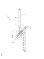
以下、添付した図面に基づいて、この発明による物品整列供給装置の実施例を説明する。図1はこの発明による物品整列供給装置の一実施例を示す側面図、図2はその上面図である。 Hereinafter, an embodiment of an article alignment and supply apparatus according to the present invention will be described with reference to the accompanying drawings. FIG. 1 is a side view showing an embodiment of an article alignment and supply apparatus according to the present invention, and FIG. 2 is a top view thereof.
図1及び図2に示す物品整列供給装置1は、搬入側に配設されている搬入コンベア2と、搬出側に配設されている搬出コンベア3と、搬入コンベア2と搬出コンベア3との間に配設されているサーボループ装置4とを備えている。搬入コンベア2は、上流側の工程である、例えば煎餅のような食品製造物である薄板状物品P(以下、「物品P」という。)を、その製造装置からの排出や集積装置からの繰り出し等によって、ランダムに即ち送り方向の間隔が不揃いの状態で搬送する。サーボループ装置4は、ランダムに搬送されてくる物品Pを、一定間隔を置いた整列状態で搬出コンベア3に搬出する働きをする。
The article alignment and supply apparatus 1 shown in FIGS. 1 and 2 includes a carry-in
サーボループ装置4は、搬入コンベア2から搬送されてくる物品Pをそれぞれが受け取り可能な複数のバケット5を備えている。バケット5に受け取られた物品Pは、バケット5内に収容状態でループに沿って搬送される。バケット5内に収容状態で搬送されてくる物品Pは、順次、バケット5から搬出コンベア4に対して、搬出コンベア4で搬送されるときに一定間隔を置くように搬出される。
The
サーボループ装置4は、搬入コンベア2と搬出コンベア3とに対して上下方向に傾斜して配設されている。即ち、搬入コンベア2は搬出コンベア3よりも大きな高低差ではないが高い位置に配置されており、サーボループ装置4は、側面図である図1に示すように、搬入コンベア2側の端部を搬入コンベア2よりも低い位置にそして搬出コンベア3側の端部を搬出コンベア3よりも高い位置に置くように、上下方向に傾斜して配設されている。サーボループ装置4における物品Pの搬送ループは、搬入コンベア2から搬入された物品Pを傾斜の上側寄りの経路を経て搬出コンベア3に搬出するループ部分である。上面図である図2示すように、搬入コンベア2は、サーボループ装置4の傾斜昇り経路に沿って配置され、搬出コンベア3はサーボループ装置4の傾斜下り経路に沿って配置されており、搬入コンベア2と搬出コンベア3は横方向にオフセットして配置されている。
The
搬入コンベア2とサーボループ装置4との間には、搬入コンベア2で搬送されてくる物品Pをサーボループ装置4の物品受取り位置6に到来したバケット5に受け渡すための投入シュート7が配設されている。また、サーボループ装置4と搬出コンベア3との間には、サーボループ装置4のバケット5内に収容されて物品受渡し位置8に搬送されてくる物品Pを搬出コンベア3に受け渡すための搬出シュート9が配設されている。
Between the carry-in
したがって、物品整列供給装置1によれば、搬入コンベア2によって物品Pがランダムに搬送されてくると、物品Pは投入シュート7によってサーボループ装置4の物品受取り位置6に到来しているバケット5に投入されることでバケット5に受け取られる。サーボループ装置4においては、物品Pはバケット5内に収容状態で上記のループ部分に沿って搬送される。そして、バケット5に収容状態で物品受渡し位置8に搬送されてくる物品Pは、バケット5から搬出シュート9に受け渡されて、搬出シュート9を経て搬出コンベア3に搬出される。サーボループ装置4の作動には駆動源(後述するサーボモータ)を要するが、サーボループ装置4における物品Pの投入シュート7からの受取りと搬出シュート9への受渡しとは、いずれも重力を利用したシュートによる投入・搬出であって特別の駆動機構を有する装置によって行われるものではない。したがって、サーボループ装置4における物品Pの受取りと受渡しを簡素な構造にて且つ駆動源を要しない省エネルギーにて行うことができる。
Therefore, according to the article alignment supply device 1, when the articles P are randomly conveyed by the carry-in
物品整列供給装置1において、サーボループ装置4は、図3及び図4にも詳細に示されているように、機械フレームに対して不動であって上下方向に傾斜して取り付けられているベース10と、上下方向に傾斜して置かれており且つベース10に対して傾斜の昇降方向にスライド可能に配置されているスライド体11とを備えている。ベース10は、傾斜方向に対して左右の側に、当該傾斜方向に延びる傾斜面12,12を備えている。傾斜面12,12は,面一な共通面内に置かれている面である。スライド体11においても、その傾斜方向両端側において、それぞれ、左右の傾斜面12,12と面一に接続する傾斜面13,13を有している。ベース10には、左右の傾斜面12,12間に形成されている凹部14の凹部底において、傾斜方向に延びるレール15が取り付けられている。また、スライド体11は、レール15に嵌合し且つレール15が延びる方向にスライド可能なスライド部材16を備えている。したがって、スライド体11は、ベース10に対して傾斜方向にスライド可能である。ベース10の傾斜面12,12及びスライド体11の傾斜面13,13は、サーボループ装置4の搬送面を定めている。
In the article alignment and supply device 1, the
サーボループ装置4は、スライド体11に対して昇り下り方向に隔置して且つ回転可能に支持されて配置された二つの回転体17,18を備えている。回転体17,18は、傾斜面12,13に平行な面内で回転可能である。回転体17,18には、無端帯19が巻き掛けられてループを形成している。無端帯19には、複数のバケット5が当該ループに沿って等間隔に並べて取り付けられている。各バケット5は、ベース10やスライド体11の傾斜面12,13の直上を当該傾斜面12,13に沿って移動可能である。回転体17,18及び無端帯19は、この実施例では、二つのスプロケットと当該スプロケットに噛み合い係合するチェーンとされており、かかる噛み合いによって、各バケット5の滑りのない確実な位置制御を可能にしている。ベース10及びスライド体11については、物品Pが食品であることを考慮して、適宜分割構成も可能であり、機械フレームに対して取り外し可能とすることで洗浄や清掃・消毒等の衛生面での対応を取ることもできる。チェーン・スプロケットに代えて、歯付きのタイミングベルト・タイミングプーリを用いることも可能である。
The
無端帯19は、二つの回転体17,18にそれぞれ巻き掛けられている二つの巻掛け走行路20,21と両巻掛け走行路20,21間を繋ぐ直線状の搬入側走行路22と搬出側走行路23とを含んで循環するループを形成している。搬入側走行路22は、サーボループ装置4の傾斜昇り経路にあり、搬出側走行路23はサーボループ装置4の傾斜下り経路にある。無端帯19の搬入側走行路22と搬出側走行路23の外側側方には、無端帯19と噛み合い係合する回転体(スプロケット)26,27が配置されており、それぞれサーボモータ24,25によって駆動される。サーボモータ24,25の出力制御により、回転体26,27をそれぞれ独立して駆動可能である。図3及び図4に示すように、回転体26,27はベース10の内部に形成された窪み28,29内に配置されている。
The
サーボモータ24,25の出力が同じになるようにサーボ制御をすると、回転体26,27の回動量は同じになり、その回動量に応じて無端帯19が走行し、バケット5が移動する。バケット5がループに沿って移動することで、バケット5に収容された状態の物品Pが搬送される。サーボモータ24,25の出力が異なるようにサーボ制御をすると、スライド体11は、レール15とスライド部材16とがスライド係合をしていることによって、回動量の差に応じて傾斜方向に移動する。スライド体11の移動量は、回動量の差に応じた無端帯19の走行量の半分の長さに相当する。投入シュート7からランダムに到来する物品Pのバケット5への受取りは、搬入側走行路22における物品受取り位置で行われ、バケット5から搬出シュート9への物品の受渡しは、搬出側走行路23における物品受渡し位置で行われる。
When the servo control is performed so that the outputs of the
物品整列供給装置1のサーボループ装置4によれば、二つのサーボモータ24,25によって、搬入側走行路22における無端帯19の走行と、搬出側走行路23における無端帯19の走行とをサーボ制御している。ランダムに到来する物品Pをセンサで検出し、その検出情報に基づいてサーボモータ24を制御することで、回転体26の出力を介して搬入側走行路22における無端帯19の走行が制御される。それによって、ランダムに到来する物品Pを物品受取り位置においてバケット5で受け取るタイミング制御が行われる。また、サーボモータ25を制御することで、回転体27の出力を介して搬出側走行路23における無端帯19の走行が制御される。それによって、物品受渡し位置においてバケット5から物品Pを一定間隔を置いて搬出シュート9へ受け渡すタイミング制御が行われる。サーボモータ24,25の両制御によって、無端帯19の走行に伴ってバケット5が進行し、バケットに収容された状態の物品Pが搬送される。搬入側走行路22における無端帯19の走行量と、搬出側走行路23における無端帯19の走行量との間に差があると、スライド体11が移動して、物品Pを受け取る位置(物品受取り位置6)を占めるバケット5と物品Pを受け渡す位置(物品受渡し位置8)を占めるバケット5との間に存在するバケット5の数、即ち、ループに貯留される物品Pの貯留量、即ち、物品Pの数の変動を吸収することができる。
According to the
バケット5は、図5に示すように上下が開口した概して断面長四角形の筒状体である。各バケット5は、長四角形の一方の短辺側において無端帯19に起立した取付けピン30に取り付けられており、長四角形の長辺側が無端帯19の側方外側に向かって延びている。取付けピン30については、チェーンに用いられるピンを軸方向に延長した態様で設けることができる。薄板状の物品Pは、バケット5内において、板の面方向を四角形の長辺に沿わせ板厚方向を四角形の短辺に沿わせるように収容される。即ち、薄板状の物品Pは、バケット5内において起立した状態又は傾斜した状態に収容され、バケット5の数に応じて密な状態で搬送される。サーボループ装置4は傾斜しているので、物品Pは、搬入側走行路22,23を走行中には長辺側の内壁面に凭れた傾斜状態で搬送される。
As shown in FIG. 5, the
物品整列供給装置1においては、サーボループ装置4が傾斜しており、その傾斜の程度は、投入シュート7からの物品Pの受取り方向(即ち、投入シュート7による物品Pの投入方向;図1においてBで示す。)及び搬出シュート9への物品Pの受渡し方向(即ち、搬出シュート9による物品Pの搬出方向;図1においてCで示す。)が、バケット5の収容高さ方向に倣うものとなっている。バケット5の収容高さ方向は、開口が開く上下方向のことであって、図5においてDで示されている。サーボループ装置4の傾斜とバケット5の高さ方向とについて上記のように設定していることにより、物品Pは投入シュート7からバケット5内へと姿勢を殆ど維持した状態でスムーズに受け取られる。また、バケット5から搬出シュート9への物品Pの受渡しについても、物品Pはバケット5内から姿勢を殆ど変えることなく搬出シュート9へとスムーズに受け渡される。
In the article alignment and supply device 1, the
図2に示すように、物品整列供給装置1において、投入シュート7によるサーボループ装置4への物品Pの投入方向Bと、サーボループ装置4の物品受取り位置6におけるバケット5の走行方向Eとは、水平方向には横方向に振れることなく順方向に倣っている。バケット5による物品Pの受取り前後において、物品Pの移動についてはその水平方向の動きが同じ方向となり、物品Pに対する横方向の衝撃とそれによる損傷が少なくなって、バケット5にスムーズに受け取られる。また、サーボループ装置4の物品受取り位置6におけるバケット5の走行方向Eは、傾斜昇り方向とされており、サーボループ装置4の上方のスペースを利用して搬入コンベア2と投入シュート7を配置することができるとともに、サーボループ装置4における物品の搬送や搬送状態のチェックが容易になる。本実施例では、搬入コンベア2による物品Pの搬入方向Fについても、投入シュート7による物品の送り込み方向Bに対して横方向に振れることなく順方向に倣う方向となっており、この場合には、搬入コンベア2、投入シュート7及びサーボループ装置4の配置が無駄なく省スペースで簡素な配置となり、物品Pの移動についても水平方向の動きが同じ方向に倣うので、物品Pへの衝撃の度合いを更に小さくすることができる。
As shown in FIG. 2, in the article alignment and supply device 1, the loading direction B of the article P into the
サーボループ装置4の物品受渡し位置8におけるバケット5の走行方向Gと、サーボループ装置4のバケット5から搬出シュート9への物品Pの受渡し方向Cとは、水平方向には横方向に振れることなく逆順方向に倣っている。サーボループ装置4から搬出シュート9への物品受渡し前後において、物品Pの移動の方向について水平方向の動きとしては逆順方向となっても、物品Pの横方向の衝撃とそれによる損傷が小さく、スムーズな受渡しを行わせることができる。更に、サーボループ装置4の物品受渡し位置8におけるバケット5の走行方向Gは傾斜下り方向となっているので、サーボループ装置4の下方のスペースを利用して搬出シュート9と搬出コンベア3を配置することができる。本実施例では、搬出コンベア3による物品Pの搬出方向Hについても、搬出シュート9による物品Pの搬出方向Cに対して横方向に振れることなく順方向に倣う方向となっており、この場合には、サーボループ装置4、搬出シュート9及び搬出コンベア3の配置が無駄なく省スペースで簡素な配置となり、物品Pの移動についても水平方向には直線状に整列するので、物品Pへの特に横方向の衝撃の度合いを小さくすることができる。
The traveling direction G of the
ベース10には、図1に破線で示すように、搬出側走行路23に置かれる物品受渡し位置8に対応して、搬出シュート9に繋がる排出孔31が形成されている。搬出側走行路23を走行するバケット5が排出孔31に整合したとき、バケット5内に収容されていた物品Pは、排出孔31を通じて搬出シュート9に受け渡される。ベース10には、物品受渡し位置8に対応して、物品Pが通り抜ける排出孔31を形成するだけでよく、ベース10の構造が極めて簡素である。バケット5が単に筒状体に形成されている場合には、各走行路20,21,22,23を走行する際に、バケット5内に収容されている物品Pがベース10の傾斜面12,13上を摺接する。バケット5の形状、特に底部の構造について、例えば、進行方向後ろ側の一部に底部を形成するなどの工夫をすることによって、搬出側走行路23以外の走行路を走行する際には、物品Pがベース10及びスライド体11の傾斜面12,13に直接に摺接するのを極力回避することができる。
As shown by a broken line in FIG. 1, the
図6には、物品整列供給装置1に用いられるサーボループ装置4のスライド体11の支持構造の一例が示されている。スライド体11はベース10にスライド支持されているので、回転体17,18及び無端帯19とそれらを支持するスライド体11(取付けピン30及びスライド部材16を含む。)とからなるスライド組立体35には、その合計重さに比例して、傾斜下り方向の落下力が作用する。かかる落下力に対抗するため、ベース10とスライド体11との間には、スライド組立体35を傾斜上方に引き上げる方向にエア力を与えるエアシリンダ40が配設されている。エアシリンダ40を配設することで、サーボモータ24,25に要求される出力を低出力のものとことができる。この例では、シリンダ部41がレール15に取り付けられ、シリンダ部41内を摺動するピストン部42がスライド体11に取り付けられている。エアシリンダ40における圧力を一定圧力に精密に制御するため、エア配管44を通じて、精密レギュレータ43がエアシリンダ40に接続されている。
FIG. 6 shows an example of a support structure of the
スライド体11に作用する傾斜下り方向の落下力に対抗するために、機械的な手段としてばねを用いることが考えられる。しかしながら、ばねはその伸びに伴って復元力が変動するので、ばねによってスライド体11を傾斜昇り方向に持ち上げる力はスライド体11の昇降方向位置によって変動する。このようにばね力が変動すると、スライド組立体35を傾斜に沿って昇降させる力は、ばね力と無端帯19に与えるサーボモータ24,25による出力との合計であるので、ばね力の変動を補償するようにサーボモータ24,25による出力を制御しなければ、スライド体11の昇降方向位置に応じて変動することになり、スライド組立体35のスライド制御上、好ましくない。そこで、スライド組立体35に傾斜上方のエア力を与えるエアシリンダ40の圧力を、シリンダ部41のピストン位置に関わらず、精密レギュレータ43によって常に同じに精密制御する。これによって、スライド組立体35の昇降方向位置に関わらず、サーボループ装置4のスライド組立体35の作動、即ち、物品受取り位置6と物品受渡し位置8とにおけるバケット5の位置を常に正確に制御することができる。
In order to counter the downward falling force acting on the
物品整列供給装置1において、処理すべき物品Pは、例えば煎餅のような薄板状の食品である。搬入及び搬出コンベア2,3、投入及び搬出シュート7,9及びバケット5は、いずれも薄板状の物品Pの取扱いがし易い構造を備えており、整列供給するのに適している。また、物品整列供給装置1の次段の処理工程は、例えば、煎餅を袋包装する横型製袋充填包装機による包装工程である。横型製袋充填包装機は、特に図示しないが周知のものであって良く、帯状の包装フィルムを製筒器によって筒状に湾曲成形し、センターシーラによって両側縁部をヒートシールして筒状の包装フィルムに成形し、物品Pを横方向に送られる筒状の包装フィルム内に送り込み、エンドシーラによって筒状の包装フィルムを物品Pの前後方向両側で横断方向にシールすることにより、物品Pを内部に収容・包装した袋包装体を連続して製造する包装機である。
In the article alignment and supply apparatus 1, the article P to be processed is a thin plate-like food such as rice cracker. The carry-in and carry-out
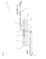
図7には、本発明による物品整列供給装置の別実施例が側面図として示されている。図7に示す物品整列供給装置50においては、図1等に示す本発明による物品整列供給装置1を構成する各要素と同等のものには、同じ符号と名称を使用することで、再度の詳細な説明を省略する。搬入コンベア2と搬出コンベア3の両搬送面間により大きな高低差があっても良い場合には、物品整列供給装置50は、搬入コンベア2の搬送面を搬出コンベア3の搬送面よりも高い位置に配置し、サーボループ装置4の搬送面を搬入コンベア2と搬出コンベア3とに対して高さ方向の中間で且つ平行、即ち、水平配置している。搬入コンベア2からサーボループ装置4への接続、即ち、物品Pのサーボループ装置4への移載には投入シュート7が用いられ、サーボループ装置4から搬出コンベア3への接続、即ち、物品Pの搬出コンベア3への移載には搬出シュート9が用いられており、いずれも、重力を利用することで駆動源を要しないシュートが利用されている。
FIG. 7 shows a side view of another embodiment of the article alignment and supply apparatus according to the present invention. In the article alignment and
以上、説明したように、物品整列供給装置1によれば、物品Pがたとえランダムに搬入されてきても、当該物品を一定間隔に整列させるに当たって、搬入コンベア2と搬出コンベア3との間において、サーボループ装置4を配設している。サーボループ装置4は、搬入コンベア2から投入シュート7によって受け取り、受け取った物品Pを起立又は傾斜した状態で収容し搬送し、そして搬出コンベア3に一定間隔を置いて搬出するために物品を搬出シュート9に受け渡す。サーボループ装置4それ自体も、特殊な構造を備えておらず、物品Pをそれぞれが受け取り且つ起立又は傾斜した状態で収容可能な複数のバケット5を備えており、簡単な構造とされている。また、サーボループ装置4への物品の受取り及び受渡しに際して、姿勢変更装置や移し替え機構のような駆動源を伴う特殊な装置を必要とせず、投入シュート7や搬出シュート9という物品Pに作用する重力を利用した駆動源を要しない簡単な構造によって、サーボループ装置4のバケット5内への物品Pの投入とバケット5からの物品Pの排出とを行うことができる。物品整列供給装置1は、その全体として、部品点数が少なく安価に製造することができ、しかも運転コストも安く且つメンテナンス費用も最小限なものとなり、物品Pがたとえランダムに搬入されてくるものであっても、当該物品Pを一定間隔に整列させる装置として極めて有用である。サーボループ装置4は、搬入コンベア2と搬出コンベア3とに対して上下方向に傾斜して配設されていてもよく、或いは搬入コンベア2が搬出コンベア3よりも高い位置に置かれている場合にはその高さ方向中間で且つ水平に配設されていてもよい。
As described above, according to the article alignment and supply device 1, even when the articles P are randomly loaded, the articles are arranged between the carry-in
1,50 物品整列供給装置 2 搬入コンベア
3 搬出コンベア 4 サーボループ装置
5 バケット 6 物品受取り位置
7 投入シュート 8 物品受渡し位置
9 搬出シュート 10 ベース
11 スライド体 12,13 傾斜面
14 凹部 15 レール
16 スライド部材 17,18 回転体
19 無端帯 20,21 巻掛け走行路
22 搬入側走行路 23 搬出側走行路
24,25 サーボモータ 26,27 回転体
28,29 窪み 30 取付けピン
31 排出孔 35 スライド組立体
40 エアシリンダ 41 シリンダ部
42 ピストン部 43 精密レギュレータ
44 エア配管
P 物品
A−A 断面
B 投入シュート7による物品Pの投入方向
C 搬出シュート9による物品Pの搬出方向
D バケット5の収容高さ方向
E 物品受取り位置6におけるバケット5の走行方向
F 搬入コンベア2による物品Pの搬入方向
G 物品受渡し位置8におけるバケット5の走行方向
H 搬出コンベア3による物品Pの搬出方向
DESCRIPTION OF
Claims (6)
搬出側に配設されていて前記物品を搬送する搬出コンベア、及び
前記搬入コンベアと前記搬出コンベアとの間に配設されていて、前記搬入コンベアから搬送されてくる前記物品をそれぞれが受け取り且つ前記物品を起立又は傾斜状態で収容可能な複数のバケットを備えており、前記バケットに受け取った前記物品を前記バケット内に収容状態でループに沿って搬送し、前記バケットに収容されて搬送されてくる前記物品を一定間隔を置いて整列して前記搬出コンベアに搬出可能とするサーボループ装置を備えており、
前記搬入コンベアと前記サーボループ装置との間には、前記搬入コンベアで搬送されてくる前記物品を前記サーボループ装置の物品受取り位置に到来した前記バケットに起立又は傾斜状態で受け渡すための投入シュートが配設されており、
前記サーボループ装置と前記搬出コンベアとの間には、前記サーボループ装置の前記バケット内に起立又は傾斜状態で収容されて物品受渡し位置に搬送されてくる前記物品を前記搬出コンベアに搬出するための搬出シュートが配設されており、
前記サーボループ装置は、前記搬入コンベアと前記搬出コンベアとに対して上下方向に傾斜して配設されており、
前記サーボループ装置の前記傾斜により、前記投入シュートによる前記物品の受取り方向及び前記搬出シュートへの前記物品の受渡し方向が、前記バケットの収容高さ方向に倣っている
ことを特徴とする物品整列供給装置。 A carry-in conveyor that is arranged on the carry-in side and conveys articles;
An unloading conveyor disposed on the unloading side for conveying the article, and an unloading conveyor disposed between the unloading conveyor and the unloading conveyor, each receiving the articles conveyed from the unloading conveyor and A plurality of buckets capable of accommodating articles in an upright or inclined state are provided, and the articles received in the bucket are conveyed along the loop in the accommodated state in the bucket, and are accommodated and conveyed in the bucket. A servo loop device is provided that enables the articles to be aligned at regular intervals and carried out to the carry-out conveyor,
Between the carry-in conveyor and the servo loop device, an input chute for delivering the article conveyed by the carry-in conveyor in an upright or inclined state to the bucket that has arrived at the article receiving position of the servo loop device Is arranged,
Between the servo loop device and the carry-out conveyor, the article that is housed in an upright or inclined state in the bucket of the servo loop device and is conveyed to the article delivery position is carried out to the carry-out conveyor. A carry-out chute is arranged ,
The servo loop device is disposed to be inclined in the vertical direction with respect to the carry-in conveyor and the carry-out conveyor,
The inclination of the servo loop device causes the receiving direction of the article by the charging chute and the delivery direction of the article to the unloading chute to follow the accommodation height direction of the bucket. Article alignment and supply device.
ことを特徴とする請求項1に記載の物品整列供給装置。 The traveling direction of the bucket at the article receiving position of the servo loop device is an ascending direction, and the traveling direction of the bucket at the article delivery position of the servo loop device is an inclined downward direction. The article alignment supply apparatus according to claim 1.
上下方向に傾斜して配置されているとともに左右に互いに平行に形成され且つ面一な共通面内に置かれた傾斜面をそれぞれ備えるベース、
前記両傾斜面間において当該ベースの傾斜昇降方向にスライド可能に配置されているスライド体、
前記スライド体に対して前記傾斜昇降方向に隔置して且つ回転可能に支持されて配置されており前記傾斜面に平行な面内で回転可能な二つの回転体、
前記二つの回転体にそれぞれ巻き掛けられる二つの巻掛け走行路と両巻掛け走行路間を繋ぐ搬入側走行路と搬出側走行路とを含んで前記ループを形成しており、前記バケットが前記ベースの前記傾斜面に沿って移動可能に前記ループに沿って並べて取り付けられている無端帯、及び
前記搬入側走行路と前記搬出側走行路とにそれぞれ配置されており、前記搬入側走行路の前記無端帯の走行と前記搬出側走行路の前記無端帯の走行とをそれぞれ独立して制御して前記物品の前記バケットへの受取りと前記バケットから前記搬出コンベアへの前記物品の受渡しとのタイミングを制御する二つのサーボモータ
を備えていることを特徴とする請求項1〜3のいずれか一項に記載の物品整列供給装置。 The servo loop device is
Bases each provided with an inclined surface arranged in a vertical direction and parallel to each other on the left and right sides and placed in a common plane.
A slide body arranged so as to be slidable in the direction of elevation of the base between the two inclined surfaces;
Two rotating bodies that are spaced apart from the slide body in the inclined up-and-down direction and are rotatably supported and arranged in a plane parallel to the inclined surface;
The loop is formed by including two winding travel paths wound around the two rotating bodies and a carry-in travel path and a carry-out travel path that connect the both travel travel paths, and the bucket includes the bucket An endless belt that is mounted side by side along the loop so as to be movable along the inclined surface of the base, and is disposed in the carry-in side travel path and the carry-out side travel path, respectively. Timing of receiving the article to the bucket and delivering the article from the bucket to the carry-out conveyor by independently controlling the running of the endless belt and the running of the endless belt of the carry-out side travel path The article alignment supply apparatus according to claim 1, further comprising two servo motors for controlling the servomotor.
前記搬出側走行路を走行する前記バケットが前記排出孔に整合したとき、前記バケット内に収容されていた前記物品が前記バケットから前記排出孔を通じて前記搬出シュートに受け渡され、
更に、前記スライド体に作用する傾斜下り方向の落下力と対抗するため、前記スライド体に傾斜上方のエア力を与えるエアシリンダと、当該エアシリンダにおける圧力を精密に制御する精密レギュレータとを備えている
ことを特徴とする請求項4に記載の物品整列供給装置。 The base has a discharge hole connected to the carry-out chute corresponding to the article delivery position,
When the bucket traveling on the carry-out side travel path is aligned with the discharge hole, the article housed in the bucket is transferred from the bucket to the carry-out chute through the discharge hole,
Further, in order to counter the falling force in the downward direction acting on the slide body, an air cylinder that applies an air force upward to the slide body and a precision regulator that precisely controls the pressure in the air cylinder are provided. The article alignment supply device according to claim 4, wherein
Priority Applications (1)
| Application Number | Priority Date | Filing Date | Title |
|---|---|---|---|
| JP2012189332A JP6109509B2 (en) | 2012-08-29 | 2012-08-29 | Article alignment supply device |
Applications Claiming Priority (1)
| Application Number | Priority Date | Filing Date | Title |
|---|---|---|---|
| JP2012189332A JP6109509B2 (en) | 2012-08-29 | 2012-08-29 | Article alignment supply device |
Publications (3)
| Publication Number | Publication Date |
|---|---|
| JP2014047002A JP2014047002A (en) | 2014-03-17 |
| JP2014047002A5 JP2014047002A5 (en) | 2015-10-08 |
| JP6109509B2 true JP6109509B2 (en) | 2017-04-05 |
Family
ID=50607065
Family Applications (1)
| Application Number | Title | Priority Date | Filing Date |
|---|---|---|---|
| JP2012189332A Active JP6109509B2 (en) | 2012-08-29 | 2012-08-29 | Article alignment supply device |
Country Status (1)
| Country | Link |
|---|---|
| JP (1) | JP6109509B2 (en) |
Families Citing this family (5)
| Publication number | Priority date | Publication date | Assignee | Title |
|---|---|---|---|---|
| JP6379012B2 (en) * | 2014-11-07 | 2018-08-22 | 大森機械工業株式会社 | Goods transfer device |
| JP6493065B2 (en) * | 2015-07-27 | 2019-04-03 | 株式会社豊田自動織機 | Article supply apparatus and article conveyance system |
| JP6615715B2 (en) * | 2016-08-08 | 2019-12-04 | 株式会社フジキカイ | Article supply equipment |
| CN110408759A (en) * | 2019-08-29 | 2019-11-05 | 河南省瑞歌传动机械有限公司 | A kind of automation feeding device |
| CN114633915B (en) * | 2022-05-19 | 2022-08-16 | 百信信息技术有限公司 | Automatic unloader of server detecting system |
Family Cites Families (4)
| Publication number | Priority date | Publication date | Assignee | Title |
|---|---|---|---|---|
| JP4112698B2 (en) * | 1998-08-13 | 2008-07-02 | 大森機械工業株式会社 | Article transport and supply equipment |
| JP2000211733A (en) * | 1999-01-22 | 2000-08-02 | Tokyo Autom Mach Works Ltd | Conveying attitude changing device of product |
| JP4039505B2 (en) * | 1999-03-16 | 2008-01-30 | オカノ電機株式会社 | Appearance inspection device |
| JP2011051642A (en) * | 2009-09-03 | 2011-03-17 | Oji Nepia Co Ltd | Box transporting posture changing device and method |
-
2012
- 2012-08-29 JP JP2012189332A patent/JP6109509B2/en active Active
Also Published As
| Publication number | Publication date |
|---|---|
| JP2014047002A (en) | 2014-03-17 |
Similar Documents
| Publication | Publication Date | Title |
|---|---|---|
| US7900766B2 (en) | Conveyance device and packing device provided therewith | |
| EP2060495A1 (en) | Conveyance device, and box packing device and box packing system with the same | |
| JP6109509B2 (en) | Article alignment supply device | |
| JP5704705B2 (en) | Product supply / stacking apparatus and product supply / stacking method | |
| JP5628548B2 (en) | Boxing equipment | |
| US7475768B2 (en) | Accumulation device and box packing system having same | |
| JP2012201409A (en) | Cartoner | |
| JP5409140B2 (en) | PTP sheet group supply device and product supply system using the same | |
| MX2012004300A (en) | A slip conveyor. | |
| JP2013086827A (en) | Stacking device for package | |
| JP2013508242A (en) | Equipment for forming product batches for loading into containers | |
| JP2014047002A5 (en) | ||
| KR101753145B1 (en) | Arrangement apparatus of liquid storage pouch | |
| JP2007217020A (en) | Automatic commercial product stacking method and machine therefor | |
| JP2008013227A (en) | Transfer device and boxing apparatus equipped with the same | |
| JP4844989B2 (en) | Supply device for horizontal bag making and filling machine and control method thereof | |
| JP2020066503A (en) | Conveying device | |
| JP6254041B2 (en) | Article conveying device | |
| US8052371B2 (en) | Bag supply apparatus | |
| JP2021102448A (en) | Article accumulation transfer device | |
| JP2016179896A (en) | Conveyor system control method and conveyor system | |
| JP2008019085A (en) | Carrying device and boxing apparatus having it | |
| JP4182411B2 (en) | Article conveying device | |
| JP6472623B2 (en) | Stacking device | |
| JP2007137624A (en) | Conveying device |
Legal Events
| Date | Code | Title | Description |
|---|---|---|---|
| A521 | Request for written amendment filed |
Free format text: JAPANESE INTERMEDIATE CODE: A523 Effective date: 20150824 |
|
| A621 | Written request for application examination |
Free format text: JAPANESE INTERMEDIATE CODE: A621 Effective date: 20150824 |
|
| A977 | Report on retrieval |
Free format text: JAPANESE INTERMEDIATE CODE: A971007 Effective date: 20160517 |
|
| A131 | Notification of reasons for refusal |
Free format text: JAPANESE INTERMEDIATE CODE: A131 Effective date: 20160705 |
|
| A521 | Request for written amendment filed |
Free format text: JAPANESE INTERMEDIATE CODE: A523 Effective date: 20160905 |
|
| TRDD | Decision of grant or rejection written | ||
| A01 | Written decision to grant a patent or to grant a registration (utility model) |
Free format text: JAPANESE INTERMEDIATE CODE: A01 Effective date: 20170228 |
|
| A61 | First payment of annual fees (during grant procedure) |
Free format text: JAPANESE INTERMEDIATE CODE: A61 Effective date: 20170308 |
|
| R150 | Certificate of patent or registration of utility model |
Ref document number: 6109509 Country of ref document: JP Free format text: JAPANESE INTERMEDIATE CODE: R150 |
|
| R250 | Receipt of annual fees |
Free format text: JAPANESE INTERMEDIATE CODE: R250 |
|
| R250 | Receipt of annual fees |
Free format text: JAPANESE INTERMEDIATE CODE: R250 |