JP6105055B2 - System for joining bones - Google Patents
System for joining bones Download PDFInfo
- Publication number
- JP6105055B2 JP6105055B2 JP2015510391A JP2015510391A JP6105055B2 JP 6105055 B2 JP6105055 B2 JP 6105055B2 JP 2015510391 A JP2015510391 A JP 2015510391A JP 2015510391 A JP2015510391 A JP 2015510391A JP 6105055 B2 JP6105055 B2 JP 6105055B2
- Authority
- JP
- Japan
- Prior art keywords
- fastening member
- caulking
- region
- surrounding
- bone
- Prior art date
- Legal status (The legal status is an assumption and is not a legal conclusion. Google has not performed a legal analysis and makes no representation as to the accuracy of the status listed.)
- Active
Links
- 210000000988 bone and bone Anatomy 0.000 title claims description 123
- 238000002788 crimping Methods 0.000 claims description 16
- 238000001356 surgical procedure Methods 0.000 claims description 4
- 210000001847 jaw Anatomy 0.000 description 133
- 210000001562 sternum Anatomy 0.000 description 89
- 238000000034 method Methods 0.000 description 76
- 238000010168 coupling process Methods 0.000 description 72
- 230000008878 coupling Effects 0.000 description 71
- 238000005859 coupling reaction Methods 0.000 description 71
- 238000009434 installation Methods 0.000 description 21
- 230000006835 compression Effects 0.000 description 18
- 238000007906 compression Methods 0.000 description 18
- 230000036961 partial effect Effects 0.000 description 17
- 210000000845 cartilage Anatomy 0.000 description 11
- 210000000038 chest Anatomy 0.000 description 9
- QTCANKDTWWSCMR-UHFFFAOYSA-N costic aldehyde Natural products C1CCC(=C)C2CC(C(=C)C=O)CCC21C QTCANKDTWWSCMR-UHFFFAOYSA-N 0.000 description 9
- ISTFUJWTQAMRGA-UHFFFAOYSA-N iso-beta-costal Natural products C1C(C(=C)C=O)CCC2(C)CCCC(C)=C21 ISTFUJWTQAMRGA-UHFFFAOYSA-N 0.000 description 9
- 210000000115 thoracic cavity Anatomy 0.000 description 8
- 230000008859 change Effects 0.000 description 7
- 239000000463 material Substances 0.000 description 7
- 239000012634 fragment Substances 0.000 description 5
- 229910052751 metal Inorganic materials 0.000 description 4
- 239000002184 metal Substances 0.000 description 4
- 230000002093 peripheral effect Effects 0.000 description 4
- 230000008901 benefit Effects 0.000 description 3
- 238000010276 construction Methods 0.000 description 3
- 229920003023 plastic Polymers 0.000 description 3
- 239000004033 plastic Substances 0.000 description 3
- 229920003229 poly(methyl methacrylate) Polymers 0.000 description 3
- 239000004926 polymethyl methacrylate Substances 0.000 description 3
- -1 polytetrafluoroethylene Polymers 0.000 description 3
- 230000002829 reductive effect Effects 0.000 description 3
- 239000004696 Poly ether ether ketone Substances 0.000 description 2
- 239000000560 biocompatible material Substances 0.000 description 2
- 229920001577 copolymer Polymers 0.000 description 2
- 230000000670 limiting effect Effects 0.000 description 2
- 230000013011 mating Effects 0.000 description 2
- 229920000747 poly(lactic acid) Polymers 0.000 description 2
- 229920002530 polyetherether ketone Polymers 0.000 description 2
- 229920002338 polyhydroxyethylmethacrylate Polymers 0.000 description 2
- 239000004626 polylactic acid Substances 0.000 description 2
- 229920000642 polymer Polymers 0.000 description 2
- 229920001343 polytetrafluoroethylene Polymers 0.000 description 2
- 239000004810 polytetrafluoroethylene Substances 0.000 description 2
- 238000000926 separation method Methods 0.000 description 2
- RBMHUYBJIYNRLY-UHFFFAOYSA-N 2-[(1-carboxy-1-hydroxyethyl)-hydroxyphosphoryl]-2-hydroxypropanoic acid Chemical compound OC(=O)C(O)(C)P(O)(=O)C(C)(O)C(O)=O RBMHUYBJIYNRLY-UHFFFAOYSA-N 0.000 description 1
- ALRHLSYJTWAHJZ-UHFFFAOYSA-N 3-hydroxypropionic acid Chemical compound OCCC(O)=O ALRHLSYJTWAHJZ-UHFFFAOYSA-N 0.000 description 1
- OZJPLYNZGCXSJM-UHFFFAOYSA-N 5-valerolactone Chemical compound O=C1CCCCO1 OZJPLYNZGCXSJM-UHFFFAOYSA-N 0.000 description 1
- BVKZGUZCCUSVTD-UHFFFAOYSA-L Carbonate Chemical compound [O-]C([O-])=O BVKZGUZCCUSVTD-UHFFFAOYSA-L 0.000 description 1
- 229920001661 Chitosan Polymers 0.000 description 1
- 102000008186 Collagen Human genes 0.000 description 1
- 108010035532 Collagen Proteins 0.000 description 1
- 206010017076 Fracture Diseases 0.000 description 1
- JVTAAEKCZFNVCJ-REOHCLBHSA-N L-lactic acid Chemical compound C[C@H](O)C(O)=O JVTAAEKCZFNVCJ-REOHCLBHSA-N 0.000 description 1
- 229920003171 Poly (ethylene oxide) Polymers 0.000 description 1
- 229920001244 Poly(D,L-lactide) Polymers 0.000 description 1
- 229920001397 Poly-beta-hydroxybutyrate Polymers 0.000 description 1
- 229920000954 Polyglycolide Polymers 0.000 description 1
- 229920000331 Polyhydroxybutyrate Polymers 0.000 description 1
- 229920002472 Starch Polymers 0.000 description 1
- 206010042015 Sternal fracture Diseases 0.000 description 1
- 229910001069 Ti alloy Inorganic materials 0.000 description 1
- RTAQQCXQSZGOHL-UHFFFAOYSA-N Titanium Chemical compound [Ti] RTAQQCXQSZGOHL-UHFFFAOYSA-N 0.000 description 1
- 229920010741 Ultra High Molecular Weight Polyethylene (UHMWPE) Polymers 0.000 description 1
- 241000251539 Vertebrata <Metazoa> Species 0.000 description 1
- WAIPAZQMEIHHTJ-UHFFFAOYSA-N [Cr].[Co] Chemical class [Cr].[Co] WAIPAZQMEIHHTJ-UHFFFAOYSA-N 0.000 description 1
- 239000002253 acid Substances 0.000 description 1
- 229910052586 apatite Inorganic materials 0.000 description 1
- 239000001506 calcium phosphate Substances 0.000 description 1
- 229910000389 calcium phosphate Inorganic materials 0.000 description 1
- 235000011010 calcium phosphates Nutrition 0.000 description 1
- 229920002678 cellulose Polymers 0.000 description 1
- 239000001913 cellulose Substances 0.000 description 1
- 210000003109 clavicle Anatomy 0.000 description 1
- 229920001436 collagen Polymers 0.000 description 1
- 230000000295 complement effect Effects 0.000 description 1
- 239000004020 conductor Substances 0.000 description 1
- 239000013078 crystal Substances 0.000 description 1
- 230000003247 decreasing effect Effects 0.000 description 1
- 238000006073 displacement reaction Methods 0.000 description 1
- 210000002683 foot Anatomy 0.000 description 1
- 150000004676 glycans Chemical class 0.000 description 1
- 210000002758 humerus Anatomy 0.000 description 1
- 229910052588 hydroxylapatite Inorganic materials 0.000 description 1
- JJTUDXZGHPGLLC-UHFFFAOYSA-N lactide Chemical compound CC1OC(=O)C(C)OC1=O JJTUDXZGHPGLLC-UHFFFAOYSA-N 0.000 description 1
- 210000002414 leg Anatomy 0.000 description 1
- 210000004072 lung Anatomy 0.000 description 1
- 210000004373 mandible Anatomy 0.000 description 1
- 210000001872 metatarsal bone Anatomy 0.000 description 1
- 229920005615 natural polymer Polymers 0.000 description 1
- 210000000056 organ Anatomy 0.000 description 1
- 230000001009 osteoporotic effect Effects 0.000 description 1
- 238000004806 packaging method and process Methods 0.000 description 1
- 210000004197 pelvis Anatomy 0.000 description 1
- VSIIXMUUUJUKCM-UHFFFAOYSA-D pentacalcium;fluoride;triphosphate Chemical compound [F-].[Ca+2].[Ca+2].[Ca+2].[Ca+2].[Ca+2].[O-]P([O-])([O-])=O.[O-]P([O-])([O-])=O.[O-]P([O-])([O-])=O VSIIXMUUUJUKCM-UHFFFAOYSA-D 0.000 description 1
- XYJRXVWERLGGKC-UHFFFAOYSA-D pentacalcium;hydroxide;triphosphate Chemical compound [OH-].[Ca+2].[Ca+2].[Ca+2].[Ca+2].[Ca+2].[O-]P([O-])([O-])=O.[O-]P([O-])([O-])=O.[O-]P([O-])([O-])=O XYJRXVWERLGGKC-UHFFFAOYSA-D 0.000 description 1
- 229920001434 poly(D-lactide) Polymers 0.000 description 1
- 229920001432 poly(L-lactide) Polymers 0.000 description 1
- 239000005014 poly(hydroxyalkanoate) Substances 0.000 description 1
- 229920002463 poly(p-dioxanone) polymer Polymers 0.000 description 1
- 229920001610 polycaprolactone Polymers 0.000 description 1
- 239000004632 polycaprolactone Substances 0.000 description 1
- 239000000622 polydioxanone Substances 0.000 description 1
- 229920000728 polyester Polymers 0.000 description 1
- 239000004633 polyglycolic acid Substances 0.000 description 1
- 229920001184 polypeptide Polymers 0.000 description 1
- 229920001282 polysaccharide Polymers 0.000 description 1
- 239000005017 polysaccharide Substances 0.000 description 1
- 229920000166 polytrimethylene carbonate Polymers 0.000 description 1
- 102000004196 processed proteins & peptides Human genes 0.000 description 1
- 108090000765 processed proteins & peptides Proteins 0.000 description 1
- 230000002441 reversible effect Effects 0.000 description 1
- 210000001991 scapula Anatomy 0.000 description 1
- 210000003625 skull Anatomy 0.000 description 1
- 210000004872 soft tissue Anatomy 0.000 description 1
- 230000000087 stabilizing effect Effects 0.000 description 1
- 229910001220 stainless steel Inorganic materials 0.000 description 1
- 239000010935 stainless steel Substances 0.000 description 1
- 239000008107 starch Substances 0.000 description 1
- 235000019698 starch Nutrition 0.000 description 1
- 210000004233 talus Anatomy 0.000 description 1
- 210000002303 tibia Anatomy 0.000 description 1
- 239000010936 titanium Substances 0.000 description 1
- 229910052719 titanium Inorganic materials 0.000 description 1
- 230000007704 transition Effects 0.000 description 1
- QORWJWZARLRLPR-UHFFFAOYSA-H tricalcium bis(phosphate) Chemical compound [Ca+2].[Ca+2].[Ca+2].[O-]P([O-])([O-])=O.[O-]P([O-])([O-])=O QORWJWZARLRLPR-UHFFFAOYSA-H 0.000 description 1
- 210000000623 ulna Anatomy 0.000 description 1
- 210000000689 upper leg Anatomy 0.000 description 1
- 210000000707 wrist Anatomy 0.000 description 1
Images


Classifications
-
- A—HUMAN NECESSITIES
- A61—MEDICAL OR VETERINARY SCIENCE; HYGIENE
- A61B—DIAGNOSIS; SURGERY; IDENTIFICATION
- A61B17/00—Surgical instruments, devices or methods, e.g. tourniquets
- A61B17/56—Surgical instruments or methods for treatment of bones or joints; Devices specially adapted therefor
- A61B17/58—Surgical instruments or methods for treatment of bones or joints; Devices specially adapted therefor for osteosynthesis, e.g. bone plates, screws, setting implements or the like
- A61B17/68—Internal fixation devices, including fasteners and spinal fixators, even if a part thereof projects from the skin
- A61B17/82—Internal fixation devices, including fasteners and spinal fixators, even if a part thereof projects from the skin for bone cerclage
- A61B17/823—Internal fixation devices, including fasteners and spinal fixators, even if a part thereof projects from the skin for bone cerclage for the sternum
-
- A—HUMAN NECESSITIES
- A61—MEDICAL OR VETERINARY SCIENCE; HYGIENE
- A61B—DIAGNOSIS; SURGERY; IDENTIFICATION
- A61B17/00—Surgical instruments, devices or methods, e.g. tourniquets
- A61B17/56—Surgical instruments or methods for treatment of bones or joints; Devices specially adapted therefor
- A61B17/58—Surgical instruments or methods for treatment of bones or joints; Devices specially adapted therefor for osteosynthesis, e.g. bone plates, screws, setting implements or the like
- A61B17/68—Internal fixation devices, including fasteners and spinal fixators, even if a part thereof projects from the skin
- A61B17/80—Cortical plates, i.e. bone plates; Instruments for holding or positioning cortical plates, or for compressing bones attached to cortical plates
-
- A—HUMAN NECESSITIES
- A61—MEDICAL OR VETERINARY SCIENCE; HYGIENE
- A61B—DIAGNOSIS; SURGERY; IDENTIFICATION
- A61B17/00—Surgical instruments, devices or methods, e.g. tourniquets
- A61B17/56—Surgical instruments or methods for treatment of bones or joints; Devices specially adapted therefor
- A61B17/58—Surgical instruments or methods for treatment of bones or joints; Devices specially adapted therefor for osteosynthesis, e.g. bone plates, screws, setting implements or the like
- A61B17/68—Internal fixation devices, including fasteners and spinal fixators, even if a part thereof projects from the skin
- A61B17/82—Internal fixation devices, including fasteners and spinal fixators, even if a part thereof projects from the skin for bone cerclage
-
- A—HUMAN NECESSITIES
- A61—MEDICAL OR VETERINARY SCIENCE; HYGIENE
- A61B—DIAGNOSIS; SURGERY; IDENTIFICATION
- A61B17/00—Surgical instruments, devices or methods, e.g. tourniquets
- A61B17/56—Surgical instruments or methods for treatment of bones or joints; Devices specially adapted therefor
- A61B17/58—Surgical instruments or methods for treatment of bones or joints; Devices specially adapted therefor for osteosynthesis, e.g. bone plates, screws, setting implements or the like
- A61B17/88—Osteosynthesis instruments; Methods or means for implanting or extracting internal or external fixation devices
- A61B17/8861—Apparatus for manipulating flexible wires or straps
Landscapes
- Health & Medical Sciences (AREA)
- Orthopedic Medicine & Surgery (AREA)
- Life Sciences & Earth Sciences (AREA)
- Surgery (AREA)
- Medical Informatics (AREA)
- Engineering & Computer Science (AREA)
- Biomedical Technology (AREA)
- Heart & Thoracic Surgery (AREA)
- Nuclear Medicine, Radiotherapy & Molecular Imaging (AREA)
- Molecular Biology (AREA)
- Animal Behavior & Ethology (AREA)
- General Health & Medical Sciences (AREA)
- Public Health (AREA)
- Veterinary Medicine (AREA)
- Neurology (AREA)
- Surgical Instruments (AREA)
Description
他の資料の相互参照
以下の特許文献の各々は、本明細書において、参照によりその全体において、すべての目的のために組み込まれている。2000年1月25日に公布された米国特許第6,017,347号、2010年4月15日に発行された米国特許出願公開第2010/0094294(A1)号、および、2011年5月12日に発行された米国特許出願公開第2011/0112537(A1)号。
Cross-reference of other documents Each of the following patent documents is hereby incorporated by reference in its entirety for all purposes. U.S. Patent No. 6,017,347 issued on January 25, 2000, U.S. Patent Application Publication No. 2010/0094294 (A1) issued on April 15, 2010, and issued on May 12, 2011 US Patent Application Publication No. 2011/0112537 (A1).
胸郭または肋骨郭は、胸腔、および、心臓および肺などの胸腔内の器官を包囲する骨および軟骨から構成されている。人間では、胸郭は、典型的には、24個の肋骨、12個の胸椎、胸骨(sternumまたはbreastbone)、および肋軟骨から構成されている。助骨は、下側の2組の助骨(浮遊肋骨)を除いて、胸椎と後側で関節接合しており、肋軟骨を介して前側で胸骨に接続されている。 The thorax or rib cage is composed of the thoracic cavity and bones and cartilage that surround organs within the thoracic cavity, such as the heart and lungs. In humans, the rib cage is typically composed of 24 ribs, 12 thoracic vertebrae, sternum (sternum or breastbone), and rib cartilage. The prosthesis is articulated with the thoracic vertebra and the posterior side, except for the lower two sets of prosthesis (floating ribs), and is connected to the sternum via the costal cartilage.
心臓切開手術など、胸腔内での大きな手術は、胸郭を開く必要がある。胸郭を開くための一般的な手順には、胸骨を切断することが含まれている。外科医は、例えば、特にはJ形の切断、T形の切断、縦方向の切断、または横方向の切断で、胸骨を分断できる。胸腔での手術が終了した後、胸骨は、胸骨の断片を近づけてそれらを互いに固定することで閉じられ得る。 Large surgeries in the thoracic cavity, such as open heart surgery, require opening the thorax. A common procedure for opening the rib cage involves cutting the sternum. The surgeon can sever the sternum, for example with a J-shaped cut, a T-shaped cut, a longitudinal cut, or a transverse cut, among others. After the thoracic surgery is complete, the sternum can be closed by bringing the sternum pieces close together and fixing them together.
外科医は、ワイヤ(またはケーブル)が胸骨に沿う位置で胸骨に結合する締結法または結合法を用いて、胸骨を固定できる。各々のワイヤは、締結部材を用いて環にされた形態で固定され得る。締結部材は、骨に加えられる負荷を分散するように機能できる。その結果、締結部材は、ワイヤを骨に切り込ませようとする傾向、および/または、ワイヤを骨に切り通そうとする傾向を限定することで、骨の損傷を減らすことができる。同様に、または、代替で、締結部材は、ワイヤを弱くさせてしまうことになるワイヤの端同士を互いの周りに撚り合わせることによって締結部材なしでワイヤを固定することと比べて、ワイヤの破損を減らすことができる。 The surgeon can fix the sternum using a fastening or coupling method where the wire (or cable) is coupled to the sternum at a location along the sternum. Each wire may be secured in an annulus using a fastening member. The fastening member can function to distribute the load applied to the bone. As a result, the fastening member can reduce bone damage by limiting the tendency to cut the wire into the bone and / or the tendency to cut the wire through the bone. Similarly or in the alternative, the fastening member breaks the wire compared to securing the wire without the fastening member by twisting the ends of the wire around each other that would cause the wire to weaken. Can be reduced.
例示の締結部材は、米国特許出願公開第2010/0094294(A1)号に開示されており、ワイヤを受け入れるための板材として構成されている。ワイヤは、ループ(loop)を形成するために板材の導通路に配置でき、適切に位置決めして引っ張ることができる。そして、板材は、ループの両端を板材に締結するためにかしめ(crimp)られ、それによって、骨の周りを包囲する形態にワイヤを維持することができる。 An exemplary fastening member is disclosed in US Patent Application Publication No. 2010/0094294 (A1) and is configured as a plate for receiving a wire. The wire can be placed in the conduction path of the plate material to form a loop and can be properly positioned and pulled. The plate is then crimped to fasten the ends of the loop to the plate, thereby maintaining the wire in a form that surrounds the bone.
前述の板材によってもたらされる様々な利点にもかかわらず、より簡単な取り外し、ワイヤへのより信頼できる取り付け、より優れた調節性、より多くの設置上の選択肢など、さらなる改良がなおも必要とされている。 Despite the various advantages afforded by the aforementioned plates, further improvements are still needed, including easier removal, more reliable attachment to the wire, better adjustability, and more installation options. ing.
本発明は、骨を結合するための方法、装置、およびキット(kit)を含むシステムを提供する。システムは、包囲部材と、包囲部材を骨の一部の周りにおいてループで固定する締結部材とを備え得る。一部の実施形態では、締結部材は、特には切断窓部、かしめ工具の顎部を締結部材のかしめ領域に案内する案内開口、複数のかしめ領域、および/または、調整可能な突起部材を受け入れる開口といったものの任意の組み合わせを備え得る。 The present invention provides a method, apparatus, and system including a kit for joining bones. The system may comprise an enclosing member and a fastening member that secures the enclosing member in a loop around a portion of the bone. In some embodiments, the fastening member receives in particular a cutting window, a guide opening that guides the jaws of the caulking tool to the caulking region of the fastening member, a plurality of caulking regions, and / or adjustable projecting members. Any combination of apertures and the like may be provided.
本発明は、骨を結合するための方法、装置、およびキットを含むシステムを提供する。システムは、包囲部材と、包囲部材を骨の一部の周りにおいてループで固定する締結部材とを備え得る。一部の実施形態では、締結部材は、特には切断窓部、かしめ工具の顎部を締結部材のかしめ領域に案内する案内開口、複数のかしめ領域、および/または、調整可能な突起部材を受け入れる開口といったものの任意の組み合わせを備え得る。 The present invention provides systems including methods, devices, and kits for joining bones. The system may comprise an enclosing member and a fastening member that secures the enclosing member in a loop around a portion of the bone. In some embodiments, the fastening member receives in particular a cutting window, a guide opening that guides the jaws of the caulking tool to the caulking region of the fastening member, a plurality of caulking regions, and / or adjustable projecting members. Any combination of apertures and the like may be provided.
本開示のこれらの態様および他の態様が、以下の節、すなわち、(I)骨用の例示の締結システム、(II)例示のかしめ工具、(III)設置、(IV)システム組み合わせ、および(V)実施例で説明される。 These and other aspects of the disclosure include the following sections: (I) an exemplary fastening system for bone, (II) an exemplary crimping tool, (III) installation, (IV) a system combination, and ( V) Illustrated in the examples.
I.骨用の例示の締結システム
本節は、例示の締結システム50(骨結合システムと入れ替え可能に称される)の選択された態様を説明している。図1〜図13を参照されたい。
I. Exemplary Fastening System for Bone This section describes selected aspects of an exemplary fastening system 50 (referred to as interchangeable with a bone binding system). Please refer to FIGS.
図1は、締結システム50で閉じられた胸郭54の外科的に二分された胸骨52の前面像を示し、この場合、システム50の複数の複製の例示の結合装置60で閉じられている。ここで、左側および右側の胸骨の半分または断片64、66へと胸骨を分割する縦長の切れ目62を形成するために、胸骨はその長さに沿って切断されている。各々の結合装置60は、切れ目62に2回(つまり、正確には2回、または、少なくとも2回)架けることができ、胸骨52の一部を包囲して、胸骨の断片を一体に保持することによって胸骨を安定させ、胸郭を閉じたままにさせることができる(例えば、開胸手術の後)。別の例では、締結システムは、異なって(例えば、特には横方向、J形、T形、または、それらの組み合わせで)切断された胸骨、破砕された胸骨を安定させることができ、または、胸骨または任意の他の適切な骨に、骨に存在する切れ目があってもなくても設置できる。
FIG. 1 shows a frontal view of a surgically bisected
各々の結合装置60は、少なくとも1つの包囲部材68と、包囲部材の少なくとも2つの縦方向に離間した領域を締結部材に固定する締結部材70とを備え得る。他の例示のシステムの構成要素は、II節〜V節など、本開示のいずれかにおいて説明されている。
Each
各々の包囲部材は、十分な長さで、例えば、骨の一部を包囲するループといった、ループに配置できる任意の細長い部材であり得る。包囲部材は、骨に押し付くように引っ張られるだけの十分な強度であり得る。包囲部材は、締結部材の開口を通る包囲部材の摺動を容易にするために、滑らかな表面を有してもよく、ならびに/または、包囲部材が締結部材に取り付けられた後の摺動に抗するために、凹部および/もしくは凸部などの表面構造を含んでもよい。包囲部材は、特には円形、楕円形、多角形(例えば、四角形)、または、それらの任意の組み合わせを含む、任意の適切な断面形状を有し得る。例示の包囲部材は、ワイヤ、ケーブル、紐、縫合糸などを備えてもよい。 Each surrounding member can be any elongated member that is of sufficient length and can be placed in a loop, for example, a loop that surrounds a portion of bone. The surrounding member may be strong enough to be pulled to press against the bone. The surrounding member may have a smooth surface to facilitate sliding of the surrounding member through the opening of the fastening member and / or for sliding after the surrounding member is attached to the fastening member. In order to withstand, surface structures such as recesses and / or protrusions may be included. The enclosing member may have any suitable cross-sectional shape, including in particular circular, elliptical, polygonal (eg, square), or any combination thereof. Exemplary wrapping members may comprise wires, cables, strings, sutures, and the like.
例示の実施形態では、包囲部材は、金属から形成され得るワイヤまたはケーブルを備えている。外科用途における用語「ワイヤ」および「ケーブル」は、それぞれ、一本で撚られた構造および複数本で撚られた構造を概して指し示す。したがって、ワイヤおよびケーブルは、個別の使途および特性(例えば、個別の可撓性ならびにねじれおよびほつれの傾向)を有している。しかしながら、本開示を通じて、ワイヤまたはケーブルは、締結装置または締結方法における包囲部材として利用され得る。 In the illustrated embodiment, the enclosure member comprises a wire or cable that may be formed from metal. The terms “wire” and “cable” in surgical applications generally refer to a single twisted structure and a multiple twisted structure, respectively. Thus, wires and cables have individual uses and characteristics (eg, individual flexibility and tendency to twist and fray). However, throughout this disclosure, a wire or cable can be utilized as an enclosure member in a fastening device or method.
各々の締結部材は、固定部材または板部材と入れ替え可能に称されてもよい。締結部材は、包囲部材よりも非可撓性であってもよく、包囲部材が骨の一部の周りにそこから延びることができる安定した基盤を提供してもよい。締結部材は、少なくとも骨の最も外側において、骨の任意の適切な表面領域に隣接して配置され得る。例えば、ここでは、締結部材70は、胸骨52の前面領域に配置されている。
Each fastening member may be referred to as being interchangeable with a fixing member or a plate member. The fastening member may be less flexible than the surrounding member and may provide a stable base from which the surrounding member can extend around a portion of the bone. The fastening member may be placed adjacent to any suitable surface area of the bone, at least on the outermost side of the bone. For example, here, the
包囲部材および締結部材は、各々、任意の適切な構成部品を備え得る。各々が、任意の適切な生体適合性の材料、および/または、生体吸収性(bioresorbableもしくはbioabsorbable)の材料から形成され得る。包囲部材または締結部材に適し得る例示の生体適合性の材料には、(1)金属(例えば、チタンまたはチタン合金、コバルト-クロム合金、ステンレス鋼など)、(2)プラスチック(例えば、超高分子量ポリエチレン(UHMWPE)、ポリメタクリル酸メチル(PMMA)、ポリテトラフルオロエチレン(PTFE)、ポリエーテルエーテルケトン(PEEK)、および/またはPMMA/ポリメタクリル酸ヒドロキシエチル(PHEMA))、(3)生体吸収性材料またはポリマー(例えば、a-ヒドロキシルカルボン酸(例えば、ポリ乳酸(PLLA、PDLLA、および/またはPDLAなど)、ポリグリコール酸、ラクチド/グリコリド共重合体など)、ポリジオキサノン、ポリカプロラクトン、ポリトリメチレンカーボネート、ポリエチレンオキシド、ポリ-β-ヒドロキシ酪酸塩、ポリ-β-ヒドロキシプロピオン酸、ポリ-δ-バレロラクトン、PHB-PHVクラスのポリ(ヒドロキシアルカノエート)、他の生体吸収性のポリエステル、および/または、天然高分子(コラーゲンまたは他のポリペプチドなど、多糖(例えば、でんぷん、セルロース、および/またはキトサン)、それらの任意の共重合体など)といったポリマー)、(4)骨材料または骨などの材料(例えば、骨片、リン酸カルシウム結晶(例えば、ヒドロキシアパタイト、炭酸リン灰石など))、あるいは、(5)それらの任意の組み合わせが含まれる。 The enclosing member and the fastening member may each comprise any suitable component. Each can be formed from any suitable biocompatible material and / or bioresorbable or bioabsorbable material. Exemplary biocompatible materials that may be suitable for the enclosure or fastening member include: (1) metal (e.g., titanium or titanium alloy, cobalt-chromium alloy, stainless steel, etc.), (2) plastic (e.g., ultra high molecular weight Polyethylene (UHMWPE), polymethyl methacrylate (PMMA), polytetrafluoroethylene (PTFE), polyetheretherketone (PEEK), and / or PMMA / polyhydroxyethyl methacrylate (PHEMA)), (3) bioabsorbable Material or polymer (e.g., a-hydroxylcarboxylic acid (e.g., polylactic acid (e.g., polylactic acid (PLLA, PDLLA, and / or PDLA), polyglycolic acid, lactide / glycolide copolymer, etc.), polydioxanone, polycaprolactone, polytrimethylene carbonate) , Polyethylene oxide, poly-β-hydroxybutyrate, poly-β-hydroxypropionic acid, poly-δ-valerolactone PHB-PHV class poly (hydroxyalkanoates), other bioabsorbable polyesters, and / or natural polymers (such as collagen or other polypeptides, polysaccharides (e.g. starch, cellulose, and / or chitosan), Polymers such as any copolymer thereof), (4) bone material or material such as bone (e.g. bone fragments, calcium phosphate crystals (e.g. hydroxyapatite, apatite carbonate, etc.)), or (5) Any combination thereof is included.
包囲部材および締結部材は、同じ材料または異なる材料から形成され得る。例えば、両部材とも金属から形成されてもよく、両部材ともプラスチックから形成されてもよく、両部材とも生体吸収性であってもよく、包囲部材が金属から形成される一方で締結部材はプラスチック(生体吸収性であり得る)から形成されてもよい(または、その逆でもよい)。 The surrounding member and the fastening member may be formed from the same material or different materials. For example, both members may be formed from metal, both members may be formed from plastic, both members may be bioabsorbable, and the surrounding member is formed from metal while the fastening member is plastic. (Which may be bioabsorbable) (or vice versa).
締結システム50は、1つまたは複数の結合装置60を利用できる。例えば、この例示では、胸骨の胸骨柄72が、胸骨の周囲の周り全体というよりも各々が胸骨を通って延びる上方の2つの別々の結合装置60で、固定されている。したがって、これらのより上位に位置決めされた結合装置の各々は、胸骨の前部分のみを包囲している。対照的に、胸骨の主部74は、より下方に位置決めされた3つの結合装置60で固定されており、それらの結合装置60は、各々、胸骨52に沿う互いから離間された3つの別々の位置で、胸骨の周りに完全に延びている。
The
図2は、図1の結合装置60のうちの1つを、結合装置がかしめられる前の組み立てられた構成で示している。包囲部材68は、締結部材70から骨の一部を回って締結部材70へと戻るように延びて、ループ76と、そのループから延びると共に各々が任意の適切な長さを有する一対の自由端78、80とを形成することができる。自由端78、80は、引っ張り矢印82、84によって指示された反対方向に引っ張られて、ループ76を骨の周りに締め付けることができる。
FIG. 2 shows one of the
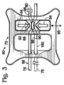
図2および図3は、それぞれ、結合装置60がかしめられる前および後の結合装置を示している。ループ76は、締結部材70の少なくとも1つのかしめ領域92(挟み領域または変形領域と入れ替え可能に称される)によって、締結部材に固定されるループ端88、90を有する。かしめ領域92は、かしめ領域の変形によって同じくかしめ(変形と入れ替え可能に称される)られ得る一方または両方のループ端88、90を係合(例えば、把持)させるために、図3において圧縮矢印94によって指示されるように、変形できる(例えば、一体的に押し付けられる)。圧縮は、圧縮軸線95(直線状または曲線状であり得る)と平行に加えられ得る。ある場合には、一対のかしめ領域が、各々、ループの個別の端を固定してもよい。図3に示した設置構成では、各々の自由端78、80は、結合装置が締結部材70の内側または外側の位置でかしめられた後、先が切り取られてもよいし(仮想輪郭線で指示されている)、切り取られなくてもよい。例えば、ここでは、両方の自由端は、先が切り取られ、または、切断されて、それぞれのループ端90および88から包囲部材の反対の長手方向の境界へと延びる切取部96、98を形成している。切取部96および98は、締結部材の周囲部の内側および外側でそれぞれ途切れている。他の実施形態では、両方の切取部が、締結部材の周囲部の内側で途切れてもよいし、または、周囲部の外側で途切れてもよい。
2 and 3 show the coupling device before and after the
ループ端88、90は、かしめ領域92において互いと重なり合ってもよい(図3参照)。それらの端は、離間された経路(例えば、平行な経路)でかしめ領域92を通って位置付けられてもよく、そのため、かしめ領域を変形することによって、互いに向かわされてもよく、および/または、互いと接触させられてもよい。ある場合には、ループ端88、90は、かしめ領域が変形される前(図2にあるように)、横側で互いに対して配置され、そして、かしめ領域が変形された後(図3にあるように)、互いの上方および下方に配置されてもよい。
The loop ends 88, 90 may overlap each other in the caulking region 92 (see FIG. 3). Their ends may be positioned through the
包囲部材68は、かしめ領域が変形される前および/または後、締結部材70に1回または複数回科架かってもよい。例えば、図2では、包囲部材68は、締結部材を越えて相対する離間部位100、102の間で締結部材を2回通すように延ばすことによって、締結部材70に2回架かっている。
The encircling
図2、図4、および図5は、締結部材70のさらなる態様を示している。締結部材は、底面領域112と反対の上面領域110を含み得る。上面領域(外側面領域と入れ替え可能に称される)は、結合装置が取り付けられる骨部分から離れる方を向くように構成され得る。底面領域(内側面領域または骨対向面領域と入れ替え可能に称される)は、結合装置が取り付けられる骨部分の方を向くように構成され得る。締結部材は、面領域110および112に直角に配置された中心高さ方向軸線114など、高さ方向軸線(垂直軸線と入れ替え可能に称される)を定めている(図4および図5参照)。
2, 4 and 5 show a further embodiment of the
ある実施形態では、締結部材は、入れ替え可能な上面領域と底面領域とを有してもよい。例えば、締結部材は、水平方向の平面に対して鏡映対称であり、いずれかの面領域が骨に向かい合う状態で締結部材を設置させることができてもよい。 In some embodiments, the fastening member may have an interchangeable top region and bottom region. For example, the fastening member may be mirror symmetric with respect to a horizontal plane, and the fastening member may be installed with any surface region facing the bone.
周囲側部壁領域116(横側部壁領域と入れ替え可能に称される)が、上面領域110と底面領域112との間に配置され、締結部材の周囲部を形成している(図4および図5参照)。横側部壁領域は、中心高さ方向軸線114を中心として展開され得る。側部壁領域は、横側部壁領域がいずれかの面領域とぶつかる締結部材の周りの各々の位置で、上面領域110および/または底面領域112との明確な縁を形成してもよいし、または、形成しなくてもよい。したがって、横側部壁領域は、締結部材の周りのいずれかの位置、もしくは、すべての位置において、一方または両方の面領域110および112へと滑らかに推移してもよいし、または、いずれの位置でも滑らかに推移しなくてもよい。
A peripheral side wall region 116 (referred to be interchangeable with the lateral side wall region) is disposed between the
締結部材は、包囲部材が締結部材および/またはそのかしめ領域を1回または複数回通って延びることができる、少なくとも1つの経路もしくは通路、または、2つ以上の経路もしくは通路が形成されてもよい。包囲部材は、締結部材に形成された架設軸線118と平行に延びてもよい(図4および図5参照)。例えば、締結部材70には、経路/通路120および122が形成される。各々の通路は、上面領域110の平均高さおよび底面領域112の平均高さの間の平均高さにおいてなどの面領域110および112の中間にある経路において、横側部壁部位100、102の間で延びることができる。したがって、包囲部材は、各通路の端同士の間で底面領域112から持ち上げられ得る。各々の経路は、一方または両方の面領域110および112と実質的に平行であってもよく、また、実質的に直線状であってもよい。
The fastening member may be formed with at least one path or passage, or two or more paths or passages through which the surrounding member may extend one or more times through the fastening member and / or its crimped area. . The surrounding member may extend in parallel to the
通路120および122は、締結部材70に形成された複数の開口によって形成できる(図4および図5参照)。各々の開口は、通路のうちの1つのみの少なくとも一部、または、2つ以上の通路の少なくとも一部を形成できる。例えば、締結部材70には、横側部壁部位100から締結部材70内へと別々に延び、通路120および122のそれぞれの端を形成する一対の導通路124および126が形成されてもよい。また、締結部材70には、反対の部位102から締結部材70内へと別々に延び、通路120および122のそれぞれの反対の端を形成する別の一対の導通路128、130が形成されてもよい。導通路124、126、128、および130は、周囲が囲まれ得る。周囲が囲まれる場合、導通路は、ここで図示するように、完全に囲まれた周囲部、または、完全に閉じられた周囲部を有する。代替で、導通路のいずれかは、閉じられた周囲部がなくてもよい(例えば、導通路の上方または下方が開いていてもよい)。各々の通路は、少なくとも1つの窓部132(図2、図4、および図5参照)、および/または、少なくとも1つの折り畳める開口134(図2および図3を比較されたい)によって部分的に形成されてもよいし、それら窓部132および/または開口134と相互作用してもよいし、および/または、それら窓部132および/または開口134を通って延びてもよい。窓部132および折り畳み可能な開口134は、各々、上面領域110から底面領域112へと延びる貫通した開口部であってもよい。
The
窓部は、締結部材に形成された大きな開口部(例えば、最大開口部)によって形成され得る。窓部は、締結部材の上面/底面領域と平行な線で測定される特徴的な寸法を有してもよく、その特徴的な寸法は、同じ線に沿って締結部材の周囲部において測定される締結部材の対応する寸法の4分の1または2分の1より大きい。代替または追加で、窓部は、締結部材の周囲部によって取り囲まれた面積の10分の1、4分の1、または2分の1より大きい面積を有してもよい。 The window portion may be formed by a large opening (for example, a maximum opening) formed in the fastening member. The window may have a characteristic dimension measured in a line parallel to the top / bottom area of the fastening member, and the characteristic dimension is measured at the periphery of the fastening member along the same line. Greater than one-quarter or one-half of the corresponding dimension of the fastening member. Alternatively or additionally, the window may have an area that is greater than one tenth, one quarter, or one half of the area surrounded by the periphery of the fastening member.
図6は、窓部132から見た導通路124および126を示している。導通路は、各々、両方の端の間で囲まれており、互いから横側において離間され得る。
FIG. 6 shows the
図7〜図10は、導通路124および126(ならびに/または、折り畳み可能な開口134の一方の側のみ、もしくは、両側の導通路128および130)に取って代わることができる開口部の他の実施形態を示している。図7は、上部で開いて垂直な壁を備える単一の凹部または凹面136を有する締結部材を示している。図8は、上部で開いた一対の凹部または凹面138を有する締結部材を示している。図9は、単一の開口部140を有する締結部材を示しており、その単一の開口部140は、開口部の主部の上方に配置されると共にその主部と連通する狭められた口部または隙間142を形成するために、上向きに先細りとなっている。開口部は、開口部において包囲部材を保持するように構成された口部142の唇部144で、包囲部材を2回受け入れるような大きさとされ得る。ある実施形態では、開口部140は、囲まれた周囲部を形成するために、上部において閉じられてもよい。図10は、一対のU字形の開口部146を有する締結部材を示している。各々の開口部の留め領域または唇部148は、開口部において包囲部材を保持できる。
FIGS. 7-10 show other paths that can replace the
図5、図11、および図12は、締結部材70の底面領域112から突出し得る、突起150などの滑り止め部を示している。滑り止め部は、位置決めするための、および/または、締結部材の骨におけるずれに抗するための、任意の下方に突出する部材であり得る。突起は、締結部材の主部から離れる方向で下方へと先細りになる任意の滑り止め部であり得る。締結部材は、なし、1つだけ、少なくとも一対、または、3つ以上といった、任意の適切な数の滑り止め部を備えることができる。各々の滑り止め部は、締結部材70にあるように、一体的に(例えば、一体品の締結部材の一部として)形成さてもよいし、または、別の部品として形成されてもよい(例えば、実施例2参照)。滑り止め部の大部分は、締結部材が設置された後、底面領域112に直角に測定される長さだけ、骨および/または骨を覆う軟組織に配置されてもよいし、または、配置されなくてもよい。滑り止め部は、回転対称および/または鏡映対称であってもよいし、または、なくてもよい。滑り止め部は、滑り止め部が底面領域112から突出する長さと、その長さに直角に測定される(最大)幅/直径とを有してもよい。長さは、幅より大きくてもよく、幅とほとんど同じでもよく、または、幅より小さくてもよい。
5, 11, and 12 show a non-slip portion such as a
図5は、締結部材70のタブ152(横側凸部と入れ替え可能に称される)の下に配置された突起150を示している。各々のタブ152は、締結部材70の丸くされた角および/または細長とされた角として形成できるか、または、特には締結部材によって形成された一対の角の中間といった、任意の他の適切な位置で締結部材の主部から突出してもよい。
FIG. 5 shows a
図11および図12は、胸骨52が仮想線で概略的に示された状態で、互いと直角に取られた締結部材70の一対の側面図を示している。各々の場合で、締結部材70の底面領域112は、突起150によって胸骨から持ち上げられている。したがって、突起は、締結部材が、図11の凸面の骨など、平面でない表面で用いられることを可能としている。骨の上方に締結部材を持ち上げることは、特には包囲部材68および/または締結部材70への工具(例えば、引っ張り工具、かしめ工具、切断工具など)のより良いアクセスなど、実質的な利点を外科医に提供できる。
FIGS. 11 and 12 show a pair of side views of the
図11は、圧縮軸線95と平行に見るとき、非対称の輪郭を有する突起150を示している。各々の突起150は、底面領域112に形成された平面156に対して斜めに配向された突起軸線154を定めてもよい。突起の内側158が凹面の輪郭であってもよく、また、突起の外側160が、特には、より抑えた凹面、直線状、または凸面の輪郭であってもよい。本明細書で描画された非対称の輪郭は、胸骨の断片の散乱を防ぐことができ、包囲部材68が引っ張られるときの胸骨52の圧縮を容易にすることができる。
FIG. 11 shows a
図12は、架設軸線118と平行に見るとき、対称の輪郭を有する突起150を示している。各々の突起の輪郭は、内側162および外側164の両方において、凹面、直線状、または凸面であってもよい。
FIG. 12 shows a
図13は、通路を通って延びる包囲部材68と共に通路122を通って取られた締結部材70の断面図を示している。締結部材70は、各々の通路120および122の反対にある端に形成された相対する一対の面取り部166、168を有してもよい(特には図4および図5も参照)。面取り部166および168の各々は、下に切り取られた(または、下に切り取られたかのように成形された)横側部壁領域116の一部に形成されて、張出部を形成してもよい。各々の面取り部は、面取り部が上面領域110から離れて底面領域112に向かって延びるにつれて、内向きに、すなわち、架設軸線118に直角な中心平面170に向かって傾斜してもよい。別の言い方をすれば、面取り部は、各々の面取り部が底面領域112に向かって延びるにつれて収束して傾斜してもよい。
FIG. 13 shows a cross-sectional view of the
下に切り取られた面取り部166および168は、面取り部のないことに対して、特に、反対の方向で傾斜する面取り部(「上に切り取られた面取り部」)に対して、実質的な利点を提供できる。結合装置の設置の間、包囲部材が環にされた形態において引っ張りを包囲部材に加えることは、締結部材を骨において逆さまの向きにひっくり返してしまう回転モーメントを締結部材に加える可能性がある。外科医は、締結部材のこの望ましくない再配向を、包囲部材が引っ張られる前に締結部材を骨にかしめることによって、防止できる。下に切り取られた面取り部は、包囲部材を引っ張ることが締結部材を骨にかしめることなく行うことができるように、正確で正しい側が上になる締結部材の配向を安定させることができ、それによって時間および労力を節約できる。
締結部材70は、各々の導通路124、126の反対の端において、窓部132の側部壁領域によって形成された面取り部172を有してもよい(図4および図13参照)。面取り部172は、少なくとも、下に切り取られた面取り部166と同じ大まかな方向で(例えば、下に切り取られた面取り部と平行に)、つまり、中心平面170に向かって傾斜する上に切り取られた面取り部であり得る。面取り部166および172は、協働して、包囲部材68により優れた回転の移動性を提供できるか、または、包囲部材68から切断された長さ方向の部分を提供できる。例えば、包囲部材は、符号174において矢印で指示された、窓部132で切断され、新しい端176、178を形成できる。面取り部166、172は、端176を上向きに回転させることを許容して、導通路126から除去するなど、その端をさらに取り扱うことを可能にする。端176は、特には、包囲部材の固定されたループの内部の部位で(例えば、ループを開いて結合装置を取り外すために)、または、ループの外部の部位で(例えば、自由端78を切断することで一片部180および切取部96を作り出すために。図3参照)、切断することによって作り出され得る。
The
図4および図5は、かしめ領域92のさらなる態様を示している。締結部材70には、かしめ工具の顎部を、かしめ領域92の両方の接触部位184に案内させて接触部位184に対して操作可能に位置決めさせることができる少なくとも1つの位置合わせ開口(例えば、一対の位置合わせ開口182)が形成されてもよい。(各々の位置合わせ開口は、案内開口と入れ替え可能に称されてもよい)。接触部位184同士は、圧縮軸線95に沿う離間された位置にそれぞれ配置さてもよく、互いから離れる方を向いてもよい。各々の接触部位は、ここで示すように、各々の位置合わせ開口182の壁領域の突出部(例えば、ボタン)によって、少なくとも一部において、提供されてもよいし、開口182の側面にある壁領域と面一とされてもよいし、または、凹面とされてもよい(例えば、実施例5参照)。あらゆる場合において、接触部位同士は、かしめ工具で押しつぶされてかしめ領域92が変形されるとき、互いに対して近づくように移動されて変形され得る(例えば、図2および図3の比較)。かしめ領域を変形すると、包囲部材のループの両端を締結部材に同時に固定できる。代替で、ループの端は、異なる時間に締結部材の一対のかしめ領域をかしめることによって、連続して固定/かしめられてもよい(例えば、実施例3、および、本明細書において参照により組み込まれている2010年4月15日に発行された米国特許出願公開第2010/0094294(A1)号を参照)。
4 and 5 show a further embodiment of the
適切と考えられる結合装置のさらなる態様は、V節において、および、関連出願として先に特定した参考文献においてなど、本開示のいずれかにおいて説明されており、それら関連出願は、本明細書において参照により組み込まれており、特には、2012年4月30日に出願された米国仮特許出願第61/640,486号、2012年5月2日に出願された米国仮特許出願第61/641,703号、2010年4月15日に発行された米国特許出願公開第2010/0094294(A1)号、および2000年1月25日に公布された米国特許第6,017,347号である。 Further embodiments of coupling devices that may be suitable are described in any of the present disclosure, such as in Section V and in the references identified above as related applications, which are referenced herein. In particular, U.S. Provisional Patent Application No. 61 / 640,486, filed Apr. 30, 2012, U.S. Provisional Patent Application No. 61 / 641,703, filed May 2, 2012, 2010. US Patent Application Publication No. 2010/0094294 (A1) issued on April 15, 2000, and US Patent No. 6,017,347 issued on January 25, 2000.
II.例示のかしめ工具
本節は、包囲部材を締結部材および骨に固定するために、本明細書で開示された締結部材のいずれかをかしめるために利用され得る例示のかしめ工具200を説明している。図14〜図17を参照されたい。
II. Exemplary Caulking Tool This section describes an
図14は、かしめ工具200を、より開いた形態(実線)(かしめる前)と、より開いていない形態(仮想線)(かしめた後)とで示している。かしめ工具は、手動で(例えば、片手のみで)係合および操作されるように構成されている一対の作動部材またはレバー204に、操作可能に接続された一対の顎部202を備えている。符号206において矢印によって指示されるように、作動レバーを互いに向かって握ると、符号208において矢印で指示されるように、顎部202も互いへと向かわされる。顎部同士の間に形成された隙間の大きさとしての、顎部同士の互いからの離間は、減少される。レバーへの圧力が十分に低減または遮断されると、付勢部材210(例えば、板バネ)は、レバー204をより開いた形態へと戻すことができる。
FIG. 14 shows the
顎部202は、回動結合部214(例えば、蝶番結合部)においてレバー204に回動可能に接続された、それぞれのかしめ部材212によって提供され得る。かしめ部材は、それぞれの回動結合部218(例えば、蝶番結合部)を各々のかしめ部材212と共に形成するために、接続部材216によって互いと接続されてもよい。
The
レバー204同士は、回動結合部220(例えば、蝶番結合部)において互いと回動可能に接続されてもよい。レバーを握ると、レバーは回動結合部220において互いに対して回動させられ、回動結合部214同士を互いから離すように移動させる。回動結合部が動くにつれて、かしめ部材212同士は回動結合部218において反対の回動方向に回動して、顎部同士を一緒により近づける。レバー204の一方または両方の近位端における移動停止部222が、レバーの互いに向かう移動の許容された範囲を定めてもよく、さらには、顎部同士が互いとどれだけ近づけるかを(そして、締結部材のかしめ領域がどれだけ変形され得るかを)定めてもよい。移動停止部は、かしめ領域が工具によってかしめ/変形される度合いを増加または減少させるために、顎部同士の最小の離間を変化させるように調整可能であってもよい。
The
図15は、顎部202が締結部材70のそれぞれの案内開口182と嵌め合わされた状態における、かしめ工具200の遠位端の部分図を示している。各々の顎部202は、対応するかしめ部材212の肩部または停止領域224に隣接して遠位に配置されている。各々の肩部224は、高さ方向軸線114に関しての顎部202の高さまたは深さを設定するために、顎部の位置合わせ開口182内への高さ方向軸線に沿って進むのを制限できる。ある実施形態では、単一の肩部または停止領域が、両方の顎部の高さを設定するのに十分であってもよい。しかしながら、各々の顎部に対して肩部または停止領域があることは、かしめ工具(例えば、工具によって定められる近位-遠位軸線)が締結部材および/もしくはかしめ領域に対して直角で、ならびに/または、工具200の圧縮軸線226がかしめ領域92の圧縮軸線95と実質的に平行に配置された状態であることを、より信頼性よく再現可能に確保できる。工具の肩部または停止領域は、概して上面領域110であって、接触部位184に隣接するかしめ領域92の上側、および/または、位置合わせ開口182の任意の他の適切な周囲領域に隣接する上面領域110の境界域など、締結部材70の任意の適切な部分と係合できる。肩部224は、図示するように、顎部が位置合わせ開口182を通って底面領域112と同じかまたは下方の位置まで進ませることができてもよい。突起150は、底面領域112を骨から持ち上げることができるため(図12参照)、顎部を底面領域112の下方へと突出させることができる。
FIG. 15 shows a partial view of the distal end of the
各々の顎部202は、顎部の位置が圧縮軸線95(および/または、架設軸線118)に沿って定められるように、位置合わせ開口182と嵌まり合うように構成されてもよい。したがって、顎部は、位置合わせ開口に密接に嵌まるように、圧縮軸線95(および/または、架設軸線118)に沿って、位置合わせ開口と対応する大きさとされてもよい。
Each
図16は、工具200がより開いた形態における(図14参照)、工具200の顎部202の遠位端の様子を示している。顎部202同士は、圧縮軸線226に直角に配置された、および/または、互いと向き合った、相対する顎部の面228を備え得る。各々の面228は横に凸面(つまり、圧縮軸線226に直角で、工具200によって定められる近位-遠位軸線232(選択的に、長手軸線)に直角な横方向軸線230に沿って凸面。図14も参照されたい)であってもよい。面228は、他方の顎部に向かって先細りとなる顎部202の突出領域234に形成されてもよい。突出領域234の先端部が面228を提供してもよい。
FIG. 16 shows the distal end of the
各々の顎部202は、互いから離れる方を向く反対にある横側部壁領域236を有してもよい。側部壁領域は、横方向軸線230に沿って互いから離間されてもよい。
Each
図17は、締結部材70がかしめられる前、図15に示すように、かしめ工具200の顎部202が位置合わせ開口182と嵌め合わされた状態における、かしめ工具200の顎部202の遠位端の様子を示している。側部壁領域236同士の間で測定される、各々の顎部の横方向の寸法は、架設軸線118と平行に測定される各々の案内開口182の特徴的な寸法に対応してもよい。開口182は、顎部がかしめ領域において中心に置かれるように、顎部をかしめ領域へと案内できる。例えば、平面237が、かしめ領域の中心部238を通って架設軸線118に直角に延びてもよく、顎部は、顎部が平面237の周りで中心に置かれる位置へと案内さえ得る。平面は、概念的に、かしめ領域を半分に分割できる。
FIG. 17 shows the distal end of the
一方または両方の横側部壁領域236は、顎部を中心に置くために、位置合わせ開口182の対応する側部壁領域と接触できる。別の言い方をすれば、位置合わせ開口182は、横方向軸線230と平行に測定された顎部202より幅広であってもよく、また、案内開口の一方の側部壁領域だけとの接触によって中心に置かれてもよい(例えば、実施例2参照)。
One or both lateral
かしめ工具および締結部材は、工具200の圧縮軸線226を締結部材の圧縮軸線と平行に、工具の横方向軸線230を締結部材の架設軸線と平行に、および/または、工具の近位-遠位軸線232を締結部材の高さ方向軸線と平行に(および/または、締結部材によって定められた平面と直角に)配置する所定の構成で、嵌め合わされるように構成されてもよい。別の言い方をすれば、位置合わせ開口182は、工具200の顎部をかしめ領域と位置合わせするように構成されてもよい。
The caulking tool and the fastening member may have a
III.設置
本節は、骨結合システムを骨に設置する例示の方法を説明している。図18〜図21を参照されたい。本節で説明されるステップは、任意の適切な順番および組み合わせで、本開示で説明される特徴の任意の適切な組み合わせを有する任意の適切な装置で実施できる。
III. Installation This section describes an exemplary method of installing a bone attachment system in bone. See FIGS. 18-21. The steps described in this section can be performed in any suitable order and in any suitable apparatus having any suitable combination of features described in this disclosure in any suitable order and combination.
少なくとも1つの骨が、安定するために選択され得る。骨は、人間または他の脊椎動物種の任意の適切な骨であり得る、または、その骨を含み得る。適切であり得る例示の骨には、とりわけ、腕(上腕骨、橈骨、および/または尺骨)、手首(手根骨)、手(中手骨および/または指骨)、脚(大腿骨、脛骨、および/または腓骨)、足(距骨、踵骨、足根骨、中足骨、および/または指骨)、肋骨、背骨、骨盤、または頭蓋、または胸骨、鎖骨、下顎骨、または肩甲骨うちの少なくとも1つの骨が含まれる。選択された骨は、不連続(例えば、切断、破砕、偽関節など)を有し得るか、または、構造的に傷つけられている可能性がある(例えば、骨粗しょう症の骨)。 At least one bone can be selected to be stable. The bone can be or include any suitable bone of a human or other vertebrate species. Exemplary bones that may be suitable include, inter alia, the arms (humerus, radius and / or ulna), wrist (carpal), hand (metacarpal and / or phalange), leg (femur, tibia), And / or ribs), feet (talus, ribs, tarsals, metatarsals, and / or phalanges), ribs, spine, pelvis, or skull, or at least the sternum, clavicle, mandible, or scapula One bone is included. The selected bone may have discontinuities (eg, cuts, fractures, false joints, etc.) or may be structurally damaged (eg, osteoporotic bone).
1つまたは複数の結合装置が、骨を安定させるために選択され得る。各々の結合装置は、締結部材と、1つまたは複数の包囲部材とを備え得る。 One or more coupling devices may be selected to stabilize the bone. Each coupling device may comprise a fastening member and one or more surrounding members.
結合装置の締結部材および包囲部材は、骨の一部の周りで組み立てできる。組み立ては、ループを形成することを含み得る。ループを形成するために、包囲部材は、締結部材の1つまたは複数の通路に配置され得る。例えば、包囲部材の両方の自由端が、締結部材の両側から締結部材のそれぞれの通路に通されてもよい。代替で、包囲部材の一端が、締結部材の第1の通路に通されてもよく、そして、同じ自由端が、締結部材の同じ側から第2の通路に(または、再び第1の通路に)通されてもよい。あらゆる場合において、組み立ての後、包囲部材は、締結部材、および/または、そのかしめ領域に2回(つまり、正確に2回または少なくとも2回)架かってもよい。 The fastening member and the surrounding member of the coupling device can be assembled around a portion of the bone. Assembly can include forming a loop. To form the loop, the enclosing member can be disposed in one or more passages of the fastening member. For example, both free ends of the surrounding member may be passed through the respective passages of the fastening member from both sides of the fastening member. Alternatively, one end of the enclosure member may be threaded through the first passage of the fastening member and the same free end from the same side of the fastening member to the second passage (or again into the first passage) ) May be passed. In all cases, after assembly, the enclosure member may be suspended twice (ie, exactly twice or at least twice) on the fastening member and / or its crimped area.
結合装置を組み立てることは、選択された骨の一部を包囲部材で包囲することを含み得る。例えば、包囲部材は、骨の周囲部の周りに完全に延びてもよいし、または、骨の周囲部によって部分的に、および、内部骨によって部分的に囲まれた骨の一部のみの周りに完全に延びてもよい。ある実施形態では、包囲部材が典型的には骨の同じ側における離間された位置で骨に出入りする状態で、外科医が骨を通して包囲部材を動かすことができる曲げられた手術針に、包囲部材が接続されてもよい。 Assembling the coupling device may include surrounding a selected portion of the bone with the surrounding member. For example, the surrounding member may extend completely around the periphery of the bone, or only around the part of the bone partially surrounded by the bone periphery and partially surrounded by the internal bone May extend completely. In certain embodiments, the surrounding member is in a bent surgical needle that allows the surgeon to move the surrounding member through the bone with the surrounding member entering and exiting the bone, typically at spaced locations on the same side of the bone. It may be connected.
締結部材は骨に位置付けられてもよい。締結部材を位置付けることで、締結部材を骨における不連続部に架けることができ、締結部材の1つまたは複数の突起を、不連続部の両側において骨に位置決めできる。締結部材は、(a)締結部材が包囲部材と共に組み立てられる前に、(b)締結部材が包囲部材と部分的に組み立てられた状態で(例えば、包囲部材がかしめ領域に1回のみ架かる状態で)、または、(c)ループを形成するために締結部材が包囲部材と組み立てられた後、ループの大きさを小さくすることによって、締結部材を骨の上の位置へと引き込むことによって、骨の上に位置付けられてもよい。 The fastening member may be positioned on the bone. Positioning the fastening member allows the fastening member to span a discontinuity in the bone and allows one or more protrusions of the fastening member to be positioned on the bone on both sides of the discontinuity. The fastening member is (a) before the fastening member is assembled with the surrounding member, and (b) with the fastening member partially assembled with the surrounding member (e.g., with the surrounding member hanging only once in the caulking region). ), Or (c) after the fastening member is assembled with the surrounding member to form a loop, by reducing the size of the loop and by pulling the fastening member to a position above the bone, It may be positioned above.
図18は、胸骨52の周りに包囲部材68および締結部材70を組み立てることによって作られ得るそれら部材の例示の組み立てを示している(図2も参照されたい)。包囲部材は、ループ76を形成するために、締結部材に2回架かってもよい。ループは、胸骨の両方の横側部において肋軟骨の整列された対同士の間で(つまり、ループが胸骨52の長手軸線に概して直角な状態で)延びてもよいし、または、肋軟骨のずれた対同士の間で延びてもよい(例えば、図3参照)。ある実施形態では、ループは、肋軟骨の任意の対同士の間で延びることなく、胸骨を通して延びてもよい(例えば、図1参照)。
FIG. 18 shows an exemplary assembly of these members that may be made by assembling the
ある実施形態では、締結部材は、複数の包囲部材と組み立てられてもよい。各々の対の包囲部材は、互いと平行または非平行に(例えば、直角または斜めに)配置されてもよい。包囲部材の対は、互いと交差してもよいし、または、交差しなくてもよい。ある実施形態では、2つ以上の対の包囲部材は、各々の対の部材が互いと交差するが他の対のいずれの部材とも交差しない状態で、締結部材と組み立てられてもよい。 In certain embodiments, the fastening member may be assembled with a plurality of surrounding members. Each pair of surrounding members may be disposed parallel or non-parallel (eg, at right angles or diagonally) to each other. The pair of surrounding members may or may not intersect each other. In some embodiments, two or more pairs of surrounding members may be assembled with a fastening member with each pair of members intersecting each other but not any other member of the other pair.
包囲部材68の両方の自由端78、80は、引っ張り矢印82、84で指示され、引っ張られてもよい。引っ張りは、自由端が手で掴まれて加えられてもよいし、および/または、引っ張り工具で加えられてもよい。例えば、自由端78、80は、引っ張り工具が操作されて包囲部材への引っ張りを増大する前に、引っ張り工具に取り付けられてもよい。適切であり得る例示の引っ張り工具は、2011年5月12日に発行された米国特許出願公開第2011/0112537(A1)号に開示されており、この特許出願は、本明細書において参照により組み込まれている。引っ張り工具の使用は、ある場合には、引っ張り工具が包囲部材の引っ張りを維持できる一方で包囲部材が固定(例えば、かしめ)されているため、有利であり得る。包囲部材を引っ張ることは、胸骨の断片64、66を互いに向かわせるなど、骨を圧縮できる。
Both free ends 78, 80 of the
図19は、包囲部材68のループ端88、90を締結部材に取り付けるために締結部材がかしめられた後の結合装置60を示している(図3も参照されたい)。包囲部材は、胸骨を圧縮する引っ張られた構成で固定され得る。締結部材は、圧縮を締結部材のかしめ領域に加えることができる任意の適切な道具でかしめることができる。例えば、図14〜図17のかしめ工具200が用いられてもよい(II節参照)。
FIG. 19 shows the
図20は、ループの外側の包囲部材の両方の端片240、242が切り取られた後の結合装置60を示している。各々の端片は、除去されてもよく(例えば、手術部位/患者から離される)、符号244において矢印によって指示されている。ここで、端片240は窓部132において包囲部材68を切断することによって作り出され、これは、窓部132に架かるループ76のみを残す。したがって、結合装置が、胸腔への再進入のため、後で取り外す必要がある場合、外科医は、締結部材に取り付けられていない分離片を作り出すことなく、窓部に架かる包囲部材を切断できる。他の実施形態では、端片240は、窓部32の外側で、つまり、図20において締結部材70の左側で、包囲部材68を切断することによって作り出され得る。
FIG. 20 shows the
図21は、胸腔に再アクセスする再進入の手順の間の結合装置60を示している。包囲部材のループは、符号246において矢印で指示された、窓部132内で切断されており、これは、包囲部材を2つの部分に分断し、それらの部分の各々がかしめ領域において締結部材に取り付けられる。ループが切断された後、包囲部材68の新しい端248は、導通路126を自由に移動できる。例えば、図21における締結部材70の左側部は、締結部材を新しい端248から滑り外すために、上向きに持ち上げられ得る(図13に相当する)。別の例として、新しい端248は、包囲部材を操作することによって、導通路126を通して引っ張られてもよいし、または、押されてもよい。あらゆる場合において、ループが切断された後、締結部材および包囲部材は、胸骨52から分離され得る。
FIG. 21 shows the
締結システムの結合装置を設置するさらなる態様は、本開示において、および、本明細書において参照により組み込まれている、関連出願として先に特定した参考文献において、いずれかに説明されている。 Additional aspects of installing the coupling device of the fastening system are described either in this disclosure and in the references previously identified as related applications, which are incorporated herein by reference.
IV.システム組み合わせ
本明細書で開示された装置は、キットとして供給され得るシステムを提供するために、任意の適切な方法で、利用されてもよいし、および/または、一まとめに集められてもよい。システム(またはキット)は、1つまたは複数の締結部材と、1つまたは複数の包囲部材とを備え得る。システムは、追加または代替で、以下のもの、つまり、引っ張り工具、かしめ工具、切断工具、および使用説明書の任意の組み合わせを備え得る。各々のシステム構成部品は、一回の使用のために(例えば、締結部材および固定部材)、または、複数回の使用のために(例えば、工具)構成され得る。システム(または、キット)の構成部品の一部または全部は、無菌容器での包装など、無菌状態で提供され得る。
IV. System Combinations The devices disclosed herein may be utilized and / or collected together in any suitable manner to provide a system that can be supplied as a kit. Also good. The system (or kit) may comprise one or more fastening members and one or more surrounding members. The system may additionally or alternatively comprise any combination of the following: a pulling tool, a caulking tool, a cutting tool, and instructions for use. Each system component may be configured for a single use (eg, a fastening member and a securing member) or for multiple uses (eg, a tool). Some or all of the components of the system (or kit) may be provided in a sterile condition, such as packaging in a sterile container.
V.実施例
以下の実施例は、骨を結合するためのシステムに関する、本開示の選択された態様および実施形態を説明している。これらの実施例は、説明のために含まれており、本開示の全体範囲を限定または定義するように意図されていない。
V. Examples The following examples illustrate selected aspects and embodiments of the present disclosure relating to a system for joining bones. These examples are included for purposes of illustration and are not intended to limit or define the overall scope of the disclosure.
(実施例1)
小さな寸法の締結部材
この実施例は、締結部材70(例えば、図2〜図5)の簡略化した形式である例示の締結部材270を説明している。図22および図23を参照されたい。
(Example 1)
Small Dimensions Fastening Member This example describes an
締結部材270は、かしめ領域92を通って延びる、架かる導通路128、130を備え得る。また、締結部材には、かしめ工具の顎部を受け入れる位置合わせ開口182が形成され得る。しかしながら、締結部材270は切断窓部を欠いてもよい。また、締結部材は、底面領域から突出する突起または他の滑り止め部を備えてもよいし、または、備えなくてもよい。締結部材は、少なくとも概して矩形であり得るし、架設軸線に対して横方向に細長とされてもよい。
The
(実施例2)
調節可能な突起を備えた結合装置
この実施例は、複数の別々の突起部材292を受け入れることができる例示の締結部材290を説明している。図24および図25を参照されたい。
(Example 2)
Coupling Device with Adjustable Protrusions This example describes an
締結部材290には、位置合わせ開口および切断窓部の両方として機能する開口294が形成され得る。開口294は、一対の位置合わせ領域296と窓部領域298とを形成するために、U字形とされてもよい。かしめ工具の顎部は、かしめ領域92をかしめるための顎部を位置決めするために、位置合わせ領域296に受け入れられてもよい。かしめ領域は、締結部材70のかしめ領域92について先に開示された構造または特徴(例えば、図2〜図5参照)の任意の適切な組み合わせを備えてもよい。位置合わせ領域296の側部壁領域302は、顎部をかしめ領域に対して中心に置くために(例えば、架設軸線118に沿って顎部の位置を定めるために)、顎部の横側部壁と当接され得る。切断工具の顎部は、包囲部材68を切断するために、窓部領域298に位置付けられてもよい。
The
締結部材290には、突起部材292を受け入れるために、開口304が形成され得る。各々の開口は、突起部材と調節可能に係合するように構成され得る。例えば、開口には雌ねじが形成されてもよく、また、突起部材には、ねじ領域306によって形成された補完的な雄ねじが形成されてもよい。突起部材は、外面的に螺合される領域から突出すると共に螺合される領域から離れる方へと選択的に先細りとなっている非螺合とされた先端部310を備えてもよい。螺合される先端部に代わって、非螺合とされる先端部が存在することは、締結部材の位置決めの調節にとって有利であり得る。例えば、締結部材の下方へと突出する突起部材の長さが、先端部を前進または後退のいずれかをするために、突起部材を回転することによって調節できる。突起部材を調節することは、先端部が骨を掘り下げる量を変化させることができる。ある場合には、先端部が骨へと捩じ込まないため、締結部材の下方へと突出する先端部の長さの変化は、締結部材の底面領域と下にある骨の表面領域との間の隙間の大きさを生成または調節し、骨の上方での締結部材の高さを変えることができる。突起部材の全部または一部のみを前進または後退させることは、締結部材を上昇または下降させて、締結部材と骨との間の離間を増加または低下させることができる。ある場合には、締結部材の少なくとも一部の高さを上昇させるために、締結部材のうちの1つまたは複数を前進させることは、包囲部材のループの引っ張りを増加させる可能性があり、これは、胸骨(または、他の骨)の断片を一体にさせる閉じる力を提供できる。代替で、突起部材(突起部材の一部など)を前進または後退させることは、締結部材(例えば、締結部材によって定められる平面)が骨に対して配向される角度を変化させることができ、これは、骨の隣接する表面領域に対する締結部材の傾きがある場合には、その傾きを増加または低下させることができる。例えば、突起部材を調節することで、骨の上方で締結部材を水平にすることができる(図25参照)。
An
各々の突起部材は、とりわけ頭部312またはねじ終了部などの停止構造を有してもよく、その構造は、突起部材の開口304を通る前進を防ぐ。ある場合には、突起部材は、頭部がなくてもよく、また、選択的に、突起部材が締結部材の上面領域の上方に突出しない位置に前進可能であってもよい(例えば、突起部材の近位端が、締結部材の上面領域と面一とされ得るか、または、締結部材の上面領域に対して窪まされ得る)。
Each protruding member may have a stop structure, such as a
本開示の締結部材のうちのいずれかに、1つまたは複数の突起部材292と任意に使用するための1つまたは複数の開口304が設けられてもよい。各々の突起部材は、締結部材が包囲部材と共に配置されてループを形成する前もしくは後、および/または、締結部材がかしめられて包囲部材を取り付ける前もしくは後といった、任意の適切なときに螺合によって締結部材に取り付けできる。
Any of the fastening members of the present disclosure may be provided with one or
(実施例3)
複数の包囲部材に固定された締結部材
この実施例は、2つ以上の包囲部材によって形成された2つ以上のループを受け入れて固定するように各々構成された例示の締結部材を説明している。図26〜図31を参照されたい。各々の締結部材は、少なくとも一対の包囲部材を、平行、直角、または斜めの締結部材を通る経路で、骨の一部の周りで、および/または、骨の長手軸線に対して、位置決めできる。包囲部材の各々の対は、互いと交差してもよいし、または、交差しなくてもよい。例えば、一対の包囲部材は、各々、部材同士が交差するように、骨の長手軸線に直角でない経路で延びてもよい。他の例では、一対の包囲部材は、平行であるため、または、平行ではないが骨に沿って互いから十分にずれているため、交差しなくてもよい。各々の対の包囲部材は、同じ窓部、別々の窓部に架かってもよいし、または、一方もしくは両方が窓部に架からなくてもよい。
(Example 3)
Fastening members secured to a plurality of surrounding members This example describes exemplary fastening members each configured to receive and secure two or more loops formed by two or more surrounding members. . See FIGS. 26-31. Each fastening member can position at least a pair of surrounding members around a portion of the bone and / or relative to the longitudinal axis of the bone, in a path through the parallel, right angle, or diagonal fastening members. Each pair of surrounding members may or may not intersect each other. For example, the pair of surrounding members may each extend along a path that is not perpendicular to the longitudinal axis of the bone so that the members intersect. In other examples, the pair of surrounding members may not intersect because they are parallel or because they are not parallel but sufficiently offset from each other along the bone. Each pair of surrounding members may span the same window, separate windows, or one or both may not span the window.
図26は、切断された胸骨52を安定させる例示の結合装置320であって、骨の一部の周りに一対の別々の包囲部材68a、68bを固定するために、一対の横方向に配置されたかしめ領域92を有する締結部材322を備える例示の結合装置320を示している。締結部材322には、各々の包囲部材68a、68bが架けられる窓部132が形成され得る。包囲部材は、各々のループ76a、76bが互いと1回または複数回交差する交差された形態で配置され得る。例えば、包囲部材同士は、窓部132において、符号324で指示された互いとの交差をしてもよく、また、胸骨52(または、骨の他の部分)の反対側(ここでは、後側)における第2の位置で互いと交差してもよい。各々のループ76aおよび76bは、各々のループの両側が胸骨52に沿った異なる位置にある状態で、胸骨52によって定められる長手軸線326に対して斜めに配置され得る。ここで、ループ76aの左側は、右側よりも上方に位置決めされており、胸骨の左側および右側のそれぞれで異なる対の肋軟骨同士の中間に延びている。ループ76bの反対側も、胸骨の左側と右側との間でループの下方から上方への構成で、異なる対の肋軟骨同士の中間に延びている。
FIG. 26 is an
各々の包囲部材68aおよび68bは、締結部材322および/または窓部132に1回または複数回架かってもよい。例えば、ここで、各々の包囲部材は、対応するかしめ領域92を2回通り、かつ、窓部132を1回のみ横切って延びる。ある実施形態では、各々の包囲部材は引っ張られてもよく、かしめ領域は包囲部材が締結部材に2回架かった状態でかしめられてもよく(例えば、図2、図18、および図19にあるように)、そして、包囲部材の端は窓部132で切り取られて切取部96を形成してもよい。
Each of the surrounding
締結部材322は、追加の包囲部材を収容するために変更されてもよい。例えば、締結部材が細長とされ、4つ以上のかしめ領域で固定された2つ以上の対の包囲部材を、各々の包囲部材が締結部材の同じ窓部に架かる状態で受け入れるように構成されてもよい。各々の対の包囲部材は互いと交差してもよく、別々の対は、互いから締結部材に沿って配置されてもよい。一方の対の部材は、他方の対の一方または両方の部材と交差してもよいし、または、交差しなくてもよい。
Fastening
ある実施形態では、締結部材322は、各々が別々の窓部を形成する2つ以上の部分を、それらの部分が締結部材の長手軸線に沿って配置された状態で形成するために、変形されてもよい。例えば、締結部材は、8の字形を集合的に形成する一対の部分を備えてもよい。各々の部分は、一対の包囲部材を、各々の対の包囲部材が他の対のいずれかの部材と交差しない状態で、交差形態で受け入れるために、締結部材322のような構造とされてもよい。
In certain embodiments, the
図27は、3つの複製の包囲部材を固定するように構成された例示の締結部材340を示している。締結部材は、上面領域110および底面領域112を提供する環体部342を備えてもよい。突起150が、底面領域112から下向きに突出してもよく、3対の通路部材344、346が、上面領域110から上向きに突出してもよい。通路部材344はかしめ領域92を提供する。通路部材346は、包囲部材を受け入れる1つの導通路348または一対の導通路を提供できる。包囲部材は、1つの導通路または一対の導通路で1回または複数回受け入れられ得る。例えば、導通路348は、包囲部材を2回受け入れる大きさとされ得る(仮想輪郭線で示されている)。
FIG. 27 shows an
環体部342および通路部材には、窓部132を集合的に形成され得る。通路部材344、346の各々の対は、締結部材および/または窓部132に1回または複数回架かる別々の包囲部材のループを受け入れて固定してもよい。ループは、窓部において骨の反対側の締結部材の外側で、骨に対して任意の適切な配向で、交差された形態で配置されてもよい。例えば、ループのうちの2つは、図26にあるように概して配置されてもよく、3番目のループは、胸骨または他の骨に対して長手方向に配向されてもよい。
図28は、交差された形態で骨の一部の周りに延びる一対の包囲部材を固定するように構成された別の締結部材360を示している。締結部材は、各々の包囲部材に対して一対の専用の導通路362または364を備え得る。導通路362および導通路364は、締結部材の底面領域の上方で異なる高さに配置されてもよいし、または、同じ高さに配置されてもよい。例えば、ここでは、導通路364は、導通路362の上方に配置されて、包囲部材が互いと干渉し得る導通路の公差を回避している。締結部材は、各々の導通路に対して別々のかしめ領域366を提供してもよく、そのかしめ領域366は、各々の包囲部材のループの端を、締結部材に個々に固定させることができる。他の実施形態では、各々の包囲部材についての対のかしめ領域366は、締結部材70のかしめ領域92など、単一のかしめ領域によって置き換えられてもよい。締結部材360に適し得る構造および特徴のさらなる態様は、2010年4月15日に発行された米国特許出願公開第2010/0094294(A1)号に説明されており、この特許出願は、本明細書において参照により組み込まれている。
FIG. 28 shows another
図29は、切断された胸骨52を安定させる一対の例示の結合装置380を示している。各々の装置380は、胸骨の長手軸線に直角で、平行な形態で胸骨の一部の周りに固定された一対の包囲部材68を、同じ締結部材382と共に備えている。各々の包囲部材は、胸骨内へと延びてもよいし、または、延びなくてもよい。
FIG. 29 illustrates a pair of
締結部材382には、各々の包囲部材68が架けられた単一の窓部132が形成されている。各々の包囲部材は、別々のかしめ領域92で固定されている。締結部材は、各々のかしめ領域を相対して側方に位置させる位置合わせ開口182を備えている。位置合わせ開口のうちの一方は、両方のかしめ領域によって共有されてもよい。
The
図30は、切断された胸骨52を安定させる一対の例示の結合装置400を示している。各々の装置400は、平行な形態で胸骨の一部の周りに固定された一対の包囲部材68を、同じ締結部材402と共に備えている。各々の包囲部材は、胸骨内へと延びてもよいし、または、延びなくてもよい。
FIG. 30 shows a pair of
締結部材402には、包囲部材のうちの一方の各々が架けられた一対の窓部132が形成されている。各々の窓部は、ここで示すように、横側で開いていてもよいし(開いた周囲部)、または、その周囲部の周りで完全に囲まれてもよい(閉じた周囲部)(例えば、図2〜図5参照)。窓部132は、締結部材402の相対する横側部で開いていてもよい。
The
各々の包囲部材は、別々のかしめ領域92で固定されている。位置合わせ開口182は、両方のかしめ領域によって共有されてもよい。かしめ領域を変形するために、かしめ工具の顎部は、一方の顎部が開口182に配置され、他方の顎部が締結部材の周囲部において横側壁領域と当接される状態で、かしめ領域の相対する側部に位置付けられ得る。
Each surrounding member is fixed by a
図31は、切断された胸骨52を安定させる一対の例示の結合装置420を示している。各々の装置420は、胸骨の長手軸線に直角で、平行な形態で胸骨の一部の周りに固定された一対の包囲部材68を、同じ締結部材422と共に備えている。各々の包囲部材は、胸骨内へと延びてもよいし、または、延びなくてもよい。締結部材422には、切断工具の顎部を受け入れるための窓部と、かしめ工具の顎部を受け入れるための位置合わせ開口との両方として機能するU字形の開口294が形成されている(図24も参照されたい)。
FIG. 31 shows a pair of
(実施例4)
周囲部の切断する窓部を備えた締結部材
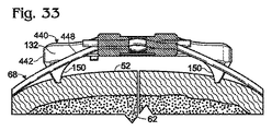
この実施例は、一対の周囲部の切断する窓部132を相対して側方に位置させる細長いタブまたは凸部442を備えた締結部材440を含む例示の結合装置を説明している。図32および図33を参照されたい。タブ442には、各々のタブの下に形成され、各々のタブから下向きに突出する突起150が各々設けられている。
(Example 4)
Fastening Member with Peripheral Cutting Window This example includes a
各々のタブ442は、締結部材の細長い角として構成されてもよい。タブは、かしめ領域92を提供する主部444から突出してもよい。タブは、締結部材の架設軸線118に平行または斜めである軸線446に沿って突出できる。例えば、軸線446は、かしめ軸線95とよりも架設軸線118とより小さい角度を形成し得る。架設軸線118と平行に測定される、締結部材および/またはタブの特徴的な寸法は、同じ軸線と平行に測定される、主部444の特徴的な寸法の少なくとも約2倍であり得る。
Each
図33は、胸骨52に配置され、包囲部材68を胸骨に固定する締結部材440を示している。タブ442は、突起150との組み合わせで、窓部132から骨に向かって延びる包囲部材の領域448を持ち上げることができる。包囲部材の持ち上げられた領域は、再進入の手順における包囲部材の切断のために、窓部132で都合よく位置決めできる。
FIG. 33 shows a
(実施例5)
雄顎部および雌顎部を用いる締結部材をかしめる
この実施例は、それぞれが凸面および凹面である顎面を提供する相対可能な顎部462、464を備える例示のかしめ工具460の使用を説明している。図34〜図36を参照されたい。
(Example 5)
Clamping fasteners using male and female jaws This example illustrates the use of an
図34は、例示の結合装置470を、工具460(図35および図36参照)でかしめる前の組み立てられた構成で示している。装置470は、締結部材472と、かしめ領域92に2回架かる包囲部材68とを備えている。
FIG. 34 shows an
かしめ領域は複数の変形可能な開口134を備えてもよく、それら開口134は、架設軸線118に沿って、または、架設軸線118の横方向で、互いと配置され得る。位置合わせ開口182は、ここで示されるように直線状に、または、凸面および/もしくは凹面である接触部位184によって、囲まれてもよい。
The caulking region may comprise a plurality of
図35は、締結部材472と嵌め合わされたかしめ工具460を、雄顎部462および雌顎部464がそれぞれの位置合わせ開口182に受け入れられた状態で示している。雄顎部462は、雌顎部464の顎面に形成される凹部476と架設軸線118に沿って位置が合わせられる突起474が形成された顎面を備え得る。
FIG. 35 shows the
図36は、顎部462、464が、かしめ領域92の相対する接触部位に、符号478において矢印で指示される圧縮力を加えるとき、顎部がかしめ領域をどのように変形できるかを示している。雄顎部は、かしめ領域の隣接する接触部位に、凹部480を形成できる。雌顎部は、凸部482を、かしめ領域の隣接する接触部位に、凹部480と位置合わせされた状態で形成できる。ある場合には、雌顎部は、かしめ領域の隣接する接触部位に、1つまたは複数の凹部484を形成してもよい。
FIG. 36 shows how the
(実施例6)
選択された実施形態
この実施例は、一連の番号付けされた段落で提示された本開示の選択された実施形態を説明している。
(Example 6)
Selected Embodiments This example describes selected embodiments of the present disclosure presented in a series of numbered paragraphs.
A1.骨を結合する方法であって、(a)かしめ領域を含む締結部材であって、締結部材の壁領域によって少なくとも部分的に囲まれた窓部が形成された締結部材を選択するステップと、(b)包囲部材を、かしめ領域に貫通させて延在させると共に骨の一部の周りにループを形成させ、壁領域の離間部位同士の間においてかしめ領域の外で窓部に架かるように配置するステップと、(c)ループの少なくとも一方の端を締結部材に固定するように、かしめ領域をかしめるステップとを含む方法。 A1. A method for joining bones, comprising: (a) selecting a fastening member including a crimped region, wherein the fastening member is formed with a window portion at least partially surrounded by a wall region of the fastening member; (B) The encircling member extends through the caulking area and forms a loop around a part of the bone so that the surrounding area extends between the spaced areas of the wall area and outside the caulking area. And (c) caulking the caulking area to secure at least one end of the loop to the fastening member.
A2.包囲部材を、窓部に架かる包囲部材の一部を通るように位置付けられた切断で分断するステップをさらに含む、段落A1に記載の方法。 A2. The method of paragraph A1, further comprising the step of dividing the enclosure member with a cut positioned to pass through a portion of the enclosure member spanning the window.
A3.包囲部材を分断するステップは、窓部に配置された切断工具で実施される、段落A2に記載の方法。 A3. The method according to paragraph A2, wherein the step of dividing the enclosing member is performed with a cutting tool arranged in the window.
A4.包囲部材を分断するステップは、かしめるステップの後にループを切断するステップを含む、段落A2に記載の方法。 A4. The method of paragraph A2, wherein the step of dividing the enclosing member includes the step of cutting the loop after the step of caulking.
A5.包囲部材を分断するステップは、ループの外側の位置で包囲部材を切り通すステップを含む、段落A2に記載の方法。 A5. The method of paragraph A2, wherein the step of dividing the enclosing member includes cutting the enclosing member at a location outside the loop.
A6.包囲部材を分断するステップは、ループに沿う第1の位置と、ループの外側の第2の位置とで、包囲部材を切り通す、段落A5に記載の方法。 A6. The method of paragraph A5, wherein the step of dividing the enclosing member cuts through the enclosing member at a first position along the loop and a second position outside the loop.
A7.配置するステップは、締結部材の上面領域が骨の部分から離れる方を向き、締結部材の底面領域が骨の部分の方を向くように、締結部材を配置するステップを含む、段落A1に記載の方法。 A7. Placing the fastening member in paragraph A1 includes the step of positioning the fastening member such that the upper surface region of the fastening member faces away from the bone portion and the bottom surface region of the fastening member faces the bone portion. The method described.
A8.配置するステップは、ループの両端が、上面領域および底面領域の間にある経路で、締結部材を貫通して延在するように、包囲部材を配置するステップを含む、段落A7に記載の方法。 A8. The paragraph A7, wherein the step of placing includes placing the enclosure member such that both ends of the loop extend through the fastening member in a path between the top region and the bottom region. Method.
A9.配置するステップは、包囲部材の一部を窓部で露出する、段落A1に記載の方法。 A9. The method according to paragraph A1, wherein the placing step exposes a part of the surrounding member at the window.
A10.締結部材は、骨に向かい合う底面領域を含み、配置するステップは、包囲部材が、壁領域の離間部位同士の各々において底面領域から持ち上げられるように、包囲部材を位置決めする、段落A1に記載の方法。 A10. The paragraph A1, wherein the fastening member includes a bottom region facing the bone and the positioning step positions the surrounding member such that the surrounding member is lifted from the bottom region at each of the spaced apart portions of the wall region. the method of.
A11.配置するステップは、包囲部材を、締結部材の窓部に2回架ける、段落A1に記載の方法。 A11. The method according to paragraph A1, wherein the placing step hangs the surrounding member twice on the window portion of the fastening member.
A12.窓部は閉じられた周囲部を含む、段落A1に記載の方法。 A12. The method of paragraph A1, wherein the window includes a closed perimeter.
A13.かしめるステップは、窓部の形を実質的に変化させない、段落A1に記載の方法。 A13. The method according to paragraph A1, wherein the step of caulking does not substantially change the shape of the window.
A14.包囲部材は、ワイヤ、ケーブル、または両方を備える、段落A1に記載の方法。 A14. The method of paragraph A1, wherein the surrounding member comprises a wire, a cable, or both.
A15.窓部はU字形である、段落A1に記載の方法。 A15. The method of paragraph A1, wherein the window is U-shaped.
A16.締結部材は一対のかしめ領域を含み、配置するステップおよびかしめるステップは、別々のかしめ領域によって各々固定された一対の包囲部材で実施される、段落A1に記載の方法。 A16. The method of paragraph A1, wherein the fastening member includes a pair of caulking areas and the placing and caulking steps are performed with a pair of surrounding members each secured by separate caulking areas.
A17.一対の包囲部材は、互いと平行な一対のループを形成する、段落A16に記載の方法。 A17. The method of paragraph A16, wherein the pair of surrounding members forms a pair of loops parallel to each other.
A18.一対の包囲部材は、互いと直角または斜めな一対のループを形成する、段落A16に記載の方法。 A18. The method of paragraph A16, wherein the pair of surrounding members forms a pair of loops that are perpendicular or diagonal to each other.
A19.一対のループは窓部で互いと交差する、段落A18に記載の方法。 A19. The method of paragraph A18, wherein the pair of loops intersect each other at the window.
A20.一対のループは窓部で互いと交差しない、段落A18に記載の方法。 A20. The method of paragraph A18, wherein the pair of loops do not intersect each other at the window.
A21.包囲部材の各々は窓部に架かる、段落A16に記載の方法。 A21. The method of paragraph A16, wherein each of the surrounding members spans a window.
A22.締結部材は一対の窓部を備え、包囲部材の各々は、一対の窓部の別々の窓部に架かる、段落A16に記載の方法。 A22. The method of paragraph A16, wherein the fastening member comprises a pair of windows and each of the surrounding members spans a separate window of the pair of windows.
A23.1つまたは複数の突起部材の各々を、締結部材と螺合させ、かつ、骨と螺合させないで配置するステップをさらに含む、段落A1に記載の方法。 A23.1. The method of paragraph A1, further comprising the step of positioning each of the one or more projecting members threadably with the fastening member and without screwing with the bone.
B1.骨を結合するためのシステムであって、(a)外科用包囲部材と、(b)かしめ領域を含む締結部材であって、締結部材の壁領域によって少なくとも部分的に囲まれた窓部が形成された締結部材とを備え、締結部材は、包囲部材がかしめ領域を2回貫通して延在すると共に骨の一部の周りにループを形成し、前記ループが壁領域の離間部位同士の間においてかしめ領域の外で窓部に架かる、包囲部材との配置を形成するように構成され、かしめ領域は、ループの両端が締結部材に固定されるように、かしめられるように構成されるシステム。 B1. A system for joining bones, comprising: (a) a surgical enclosing member; and (b) a fastening member comprising a crimped region, wherein the window is at least partially surrounded by a wall region of the fastening member A fastening member formed with the surrounding member extending through the caulking region twice and forming a loop around a portion of the bone, the loop being spaced apart from each other in the wall region Is configured to form an arrangement with the surrounding member that spans the window outside the crimped area between, and the crimped area is configured to be crimped so that both ends of the loop are secured to the fastening member system.
B2.窓部に架かる包囲部材の一部を通るように位置付けられた切断で包囲部材を分断できる切断工具をさらに備える、段落B1に記載のシステム。 B2. The system of paragraph B1, further comprising a cutting tool capable of cutting the enclosure member with a cut positioned to pass through a portion of the enclosure member over the window.
B3.切断工具は、包囲部材を分断するために窓部に操作可能に配置できる一対の顎部を有する、段落B1に記載のシステム。 B3. The system of paragraph B1, wherein the cutting tool has a pair of jaws that can be operably disposed in the window to sever the enclosure member.
B4.締結部材は、底面領域と反対の上面領域を有すると共に、包囲部材を上面領域と底面領域との間で締結部材を貫通して延在させるための経路が形成されている、段落B1に記載のシステム。 B4. The fastening member has a top surface region opposite to the bottom surface region, and a path for extending the surrounding member through the fastening member between the top surface region and the bottom surface region is formed in paragraph B1 The system described.
B5.窓部に架かる包囲部材の領域が窓部で露出される、段落B1に記載のシステム。 B5. The system of paragraph B1, wherein an area of the surrounding member that spans the window is exposed at the window.
B6.締結部材は、骨に向かい合うように構成された底面領域を含み、包囲部材は、離間部位同士の各々において底面領域から持ち上げられる、段落B1に記載のシステム。 B6. The system of paragraph B1, wherein the fastening member includes a bottom region configured to face the bone, and the surrounding member is lifted from the bottom region at each of the spaced apart sites.
B7.窓部は閉じられた周囲部を含む、段落B1に記載のシステム。 B7. The system of paragraph B1, wherein the window includes a closed perimeter.
B8.外科用包囲部材は、ワイヤ、ケーブル、または両方を備える、段落B1に記載のシステム。 B8. The system of paragraph B1, wherein the surgical wrap member comprises a wire, a cable, or both.
B9.締結部材は、包囲部材が、かしめ領域を貫通して延在することによって前記ループを形成すると共に、壁領域の離間部位同士の間においてかしめ領域の外で窓部に架かるように、包囲部材と共にすでに組み立てられており、かしめ領域は、ループの両端が締結部材に固定されるようにかしめられている、段落B1に記載のシステム。 B9. The fastening member encloses the surrounding member so that the surrounding member extends through the caulking region to form the loop and spans the window portion outside the caulking region between the separated portions of the wall region. The system of paragraph B1, wherein the system is already assembled with the member and the crimped area is crimped such that both ends of the loop are secured to the fastening member.
B10.締結部材は、1つまたは複数の包囲部材によって形成された一対のループを固定するように構成された一対のかしめ領域を含む、段落B1に記載のシステム。 B10. The system of paragraph B1, wherein the fastening member includes a pair of caulking regions configured to secure a pair of loops formed by the one or more surrounding members.
B11.一対のかしめ領域は互いと平行に配置される、段落B10に記載のシステム。 B11. The system according to paragraph B10, wherein the pair of caulking areas are arranged parallel to each other.
B12.一対のかしめ領域は互いと斜めまたは直角に配置される、段落B10に記載のシステム。 B12. The system according to paragraph B10, wherein the pair of caulking regions are arranged obliquely or at right angles to each other.
B13.締結部材は、一対のループが締結部材の窓部で互いと交差する交差形態に、一対のループを位置決めするように構成される、段落B12に記載のシステム。 B13. The system of paragraph B12, wherein the fastening member is configured to position the pair of loops in an intersecting configuration where the pair of loops intersect each other at a window of the fastening member.
B14.締結部材は、一対のループが締結部材の窓部で互いと交差しないように、一対のループを非交差形態に位置決めするように構成される、段落B12に記載のシステム。 B14. The system of paragraph B12, wherein the fastening member is configured to position the pair of loops in a non-intersecting configuration such that the pair of loops do not cross each other at a window of the fastening member.
B15.締結部材は、両方のループが締結部材の同じ窓部に架かるように、一対のループを位置決めするように構成される、段落B10に記載のシステム。 B15. The system of paragraph B10, wherein the fastening member is configured to position the pair of loops such that both loops span the same window of the fastening member.
B16.締結部材は、一対の窓部を備え、各々のループが一対の窓部の別々の窓部に架かるように、包囲部材を受け入れるように構成される、段落10に記載のシステム。 B16. The system of paragraph 10, wherein the fastening member comprises a pair of windows and is configured to receive the enclosing member such that each loop spans a separate window of the pair of windows.
B17.締結部材には複数の開口が形成され、システムは複数の突起部材をさらに備え、複数の突起部材は、各々の突起部材の先端部が骨と螺合しないために締結部材から調整可能な距離で突出する状態で、締結部材と螺合し、複数の開口に受け入れられるように構成される、段落B1に記載のシステム。 B17. A plurality of openings are formed in the fastening member, and the system further includes a plurality of projecting members, and the plurality of projecting members can be adjusted from the fastening members so that the tip of each projecting member does not screw into the bone The system of Paragraph B1, wherein the system is configured to be threadedly engaged with a fastening member and received in a plurality of openings while protruding at a distance.
B18.かしめ領域をかしめる一対の顎部を備える工具をさらに備え、締結部材には、顎部をかしめ領域へと案内するように構成された開口が形成されている、段落B1に記載のシステム。 B18. The system of paragraph B1, further comprising a tool comprising a pair of jaws for caulking the caulking area, wherein the fastening member is formed with an opening configured to guide the jaws to the caulking area .
B19.包囲部材は、架設軸線と平行な経路でかしめ領域を通って延び、開口は、工具の顎部が、架設軸線に対して直角でかしめ領域の中心部を通って延びる平面に関して中心に置かれるように、顎部をかしめ領域における位置へと案内するように構成される、段落B18に記載のシステム。 B19.The enclosure member extends through the caulking area in a path parallel to the installation axis, and the opening is centered with respect to a plane in which the tool jaws extend perpendicular to the installation axis and through the center of the caulking area. The system of paragraph B18, wherein the system is configured to guide the jaw to a position in the caulking region as it is.
B20.平面は、かしめ領域を架設軸線に沿って互いから配置された両半分に概念的に分割する、段落B19に記載のシステム。 B20. The system of paragraph B19, wherein the plane conceptually divides the caulking region into halves arranged from each other along an erection axis.
B21.包囲部材は、架設軸線と平行な経路でかしめ領域を通って延び、開口は、架設軸線と平行な線に沿う所定位置に顎部を案内するように構成される、段落B18に記載のシステム。 B21. The paragraph B18, wherein the surrounding member extends through the caulking region in a path parallel to the installation axis, and the opening is configured to guide the jaw to a predetermined position along a line parallel to the installation axis. system.
B22.かしめ領域をかしめる一対の顎部と、締結部材に接触して顎部のうちの少なくとも一方が開口を通って進むのを防ぎ、かしめ領域をかしめるために少なくとも一方の顎部の高さを設定するように構成された停止領域とを備えるかしめ工具をさらに備える、段落B1に記載のシステム。 B22. A pair of jaws for caulking the caulking area and at least one of the jaws for contacting the fastening member and preventing at least one of the jaws from passing through the opening and caulking the caulking area The system of paragraph B1, further comprising a caulking tool comprising a stop region configured to set the thickness.
B23.停止領域は工具の顎部における肩部として形成される、段落B1に記載のシステム。 B23. The system of paragraph B1, wherein the stop region is formed as a shoulder in the tool jaw.
B24.窓部は、締結部材の周囲部によって取り囲まれた面積の少なくとも4分の1である面積を含む、段落B1に記載のシステム。 B24. The system of paragraph B1, wherein the window includes an area that is at least a quarter of the area surrounded by the periphery of the fastening member.
C1.骨を結合する方法であって、(a)包囲部材を、締結部材のかしめ領域を2回貫通させて延在させるとともに、骨の一部の周りにループが形成されるように配置するステップと、(b)工具の顎部を、締結部材の開口を備えたかしめ領域に案内するステップと、(c)ループの両端を締結部材に固定するように、締結部材のかしめ領域を工具でかしめるステップとを含む方法。 C1. A method for joining bones, wherein (a) the surrounding member extends through the crimping region of the fastening member twice so that a loop is formed around a portion of the bone A step of (b) guiding the jaw of the tool to a caulking area provided with an opening of the fastening member; and (c) a caulking area of the fastening member with a tool so that both ends of the loop are fixed to the fastening member. And a step including caulking.
C2.包囲部材は、架設軸線と平行な経路でかしめ領域を貫通して延在し、案内するステップは、顎部が、架設軸線に対して直角でかしめ領域の中心部を通って延びる平面に関して中心に置かれるように、顎部を案内する、段落C1に記載の方法。 C2. The surrounding member extends through the caulking area in a path parallel to the installation axis, and the guiding step relates to a plane in which the jaws extend perpendicularly to the installation axis and through the center of the caulking area. The method of paragraph C1, wherein the jaws are guided so that they are centered.
C3.平面は、かしめ領域を架設軸線に沿って互いから配置された両半分に概念的に分割する、段落C2に記載の方法。 C3. The method according to paragraph C2, wherein the plane conceptually divides the caulking area into halves arranged from each other along the construction axis.
C4.案内するステップは、顎部を、開口の一部を囲むと共に架設軸線に対して横方向に延びる壁領域と接触するステップを含む、段落C1に記載の方法。 C4. The method of paragraph C1, wherein the guiding step includes contacting the jaw with a wall region surrounding a portion of the opening and extending transversely to the erection axis.
C5.顎部は、かしめ領域に接触する面領域と、相対する面領域の横方向に配置される横側部とを含み、開口は、案内するステップの間に、顎部の横側部と接触する壁領域を含む、段落C1に記載の方法。 C5. The jaw includes a surface area that contacts the caulking area and a lateral side that is disposed laterally of the opposing surface area, and the opening includes a lateral side of the jaw during the guiding step The method of paragraph C1, comprising a wall region that contacts.
C6.工具は一対の顎部を備え、案内するステップは、締結部材の開口が顎部の各々をかしめ領域へと案内するように、顎部を締結部材に形成される1つまたは複数の開口に配置するステップ含む、段落C1に記載の方法。 C6. The tool comprises a pair of jaws, and the step of guiding includes one or more openings formed in the fastening member such that the opening of the fastening member guides each of the jaws to the crimped area. The method of paragraph C1, comprising the step of:
C7.別々の開口が各々の顎部をかしめ領域に案内する、段落C6に記載の方法。 C7. The method of paragraph C6, wherein separate openings guide each jaw to the crimped area.
C8.顎部は、開口に対応している大きさとされる、段落C1に記載の方法。 C8. The method of paragraph C1, wherein the jaw is sized to correspond to the opening.
C9.顎部は、開口に対応している形とされる、段落C1に記載の方法。 C9. The method of paragraph C1, wherein the jaw is shaped to correspond to the opening.
C10.工具は、一対の顎部と、締結部材に接触して少なくとも1つの顎部が開口内へと進むのを防ぐことで、締結部材をかしめるために少なくとも1つの顎部の高さを設定するように構成された停止領域とを備える、段落C1に記載の方法。 C10. The tool increases the height of at least one jaw to crimp the fastening member by contacting the fastening member and preventing the at least one jaw from moving into the opening by contacting the fastening member. The method of paragraph C1, comprising a stop region configured to set.
C11.停止領域は、かしめるステップの前および/または最中に、締結部材と接触している、段落C10に記載の方法。 C11. The method of paragraph C10, wherein the stop region is in contact with the fastening member before and / or during the caulking step.
C12.停止領域は工具の顎部における肩部として形成される、段落C10に記載の方法。 C12. The method of paragraph C10, wherein the stop region is formed as a shoulder in a tool jaw.
D1.骨を結合するためのシステムであって、(a)外科用包囲部材と、(b)かしめ領域を含み、締結部材は、包囲部材が、かしめ領域を2回貫通して延在すると共に骨の一部の周りにループを形成する、包囲部材との配置を形成するように構成された締結部材であって、ループの両端が締結部材に固定されるように工具によってかしめられるように構成されたかしめ領域に、工具の顎部を案内するように構成された開口が形成されている締結部材とを備えるシステム。 D1. A system for joining bones, comprising: (a) a surgical surrounding member; and (b) a crimped region, wherein the fastening member extends twice through the crimped region Fastening member configured to form an arrangement with an encircling member that forms a loop around a portion of the bone and configured to be crimped by a tool so that both ends of the loop are secured to the fastening member And a fastening member having an opening configured to guide the jaw of the tool in the crimped area.
E1.骨を結合する方法であって、(a)第1の包囲部材および第2の包囲部材を、各々の包囲部材が締結部材を2回貫通して延在することによって骨の一部の周りに各々延びると共に互いと交差する第1のループおよび第2のループをそれぞれ形成するように配置するステップと、(b)各々のループの両端が締結部材に固定されるように、締結部材をかしめるステップとを含む方法。 E1. A method for joining bones, wherein (a) a first enclosing member and a second enclosing member are passed through a portion of the bone by each encircling member extending twice through the fastening member. Arranging to respectively form a first loop and a second loop each extending around and intersecting each other; and (b) fastening members such that both ends of each loop are fixed to the fastening members. And a step including caulking.
E2.骨は胸骨によって提供され、各々のループは胸骨に対して斜めに配向される、段落E1に記載の方法。 E2. The method of paragraph E1, wherein the bone is provided by a sternum and each loop is oriented obliquely relative to the sternum.
E3.各々のループは、胸骨の両側にある第1の対の肋軟骨と第2の対の肋軟骨との間で延び、第1の対の肋軟骨は、上位方向または下位方向において第2の対の肋軟骨からずらされる、段落E1に記載の方法。 E3. Each loop extends between a first pair of costal cartilages on either side of the sternum and a second pair of costal cartilages, the first pair of costal cartilages being second in the superior or inferior direction The method of paragraph E1, wherein the method is offset from a pair of costal cartilage.
E4.ループ同士は、胸骨の後面領域に隣接してか、胸骨内で、または、それら両方で、互いと交差する、段落E1に記載の方法。 E4. The method of paragraph E1, wherein the loops intersect each other adjacent to the posterior region of the sternum, within the sternum, or both.
E5.ループ同士は、締結部材に形成された同じ窓部で互いと交差する、段落E1に記載の方法。 E5. The method of paragraph E1, wherein the loops intersect each other at the same window formed in the fastening member.
E6.ループは互いと2回交差する、段落E1に記載の方法。 E6. The method of paragraph E1, wherein the loops intersect each other twice.
E7.締結部材は、第1のループおよび第2のループを締結部材に固定するように構成された一対のかしめ領域を含む、段落E1に記載の方法。 E7. The method of paragraph E1, wherein the fastening member includes a pair of caulking regions configured to secure the first loop and the second loop to the fastening member.
E8.一対のかしめ領域は互いと平行に配置される、段落E7に記載の方法。 E8. The method of paragraph E7, wherein the pair of caulking regions are disposed parallel to each other.
E9.一対のかしめ領域は互いと斜めまたは直角に配置される、段落E7に記載の方法。 E9. The method of paragraph E7, wherein the pair of caulking regions are disposed at an angle or perpendicular to each other.
E10.第1のループおよび第2のループは、締結部材に形成された窓部で互いと交差する交差形態で位置決めされる、段落E1に記載の方法。 E10. The method of paragraph E1, wherein the first loop and the second loop are positioned in an intersecting configuration that intersects each other at a window formed in the fastening member.
E11.第1のループおよび第2のループは、互いと交差しないように非交差形態で位置決めされる、段落E1に記載の方法。 E11. The method of paragraph E1, wherein the first loop and the second loop are positioned in a non-intersecting configuration so as not to intersect each other.
E12.両方のループは、締結部材に形成された同じ窓部に架かる、段落E1に記載の方法。 E12. The method of paragraph E1, wherein both loops span the same window formed in the fastening member.
E13.締結部材は一対の窓部を備え、各々のループは、一対の窓部の別々の窓部に架かる、段落E1に記載の方法。 E13. The method of paragraph E1, wherein the fastening member comprises a pair of windows and each loop spans a separate window of the pair of windows.
F1.骨を結合するためのシステムであって、(a)外科用包囲部材と、(b)かしめ領域を含むと共に、包囲部材がかしめ領域を2回貫通して延在することによって骨の一部の周りにループを形成するように包囲部材と配置可能な締結部材と、(c)かしめ領域をかしめる一対の顎部を備える工具とを備え、締結部材には、工具の顎部をかしめ領域へと案内するように構成された開口が形成されている、システム。 F1. A system for joining bones, comprising: (a) a surgical surrounding member; and (b) a crimping region, wherein the surrounding member extends twice through the crimping region and the bone A fastening member that can be arranged with the surrounding member so as to form a loop around the part, and (c) a tool having a pair of jaws for caulking the caulking area, and the fastening member is caulked with the jaw part of the tool. A system in which an opening configured to guide to an area is formed.
F2.包囲部材は、架設軸線と平行な経路でかしめ領域を通って延び、かしめ領域に案内された後の顎部は、架設軸線に対して直角でかしめ領域の中心部を通って延びる平面に関して中心に置かれる、段落F1に記載のシステム。 F2. The surrounding member extends through the caulking area in a path parallel to the installation axis, and the jaw after being guided to the caulking area is perpendicular to the installation axis with respect to a plane extending through the center of the caulking area The system of paragraph F1, centered.
F3.開口は、開口の一部を囲むと共に架設軸線に対して横方向に延びる壁領域を備え、壁領域は、顎部をかしめ領域へと案内するように顎部と接触するように構成される、段落F1に記載のシステム。 F3. The opening comprises a wall region that surrounds a portion of the opening and extends transversely to the erection axis, the wall region being configured to contact the jaws to guide the jaws to the caulking region The system of paragraph F1.
F4.顎部は、かしめ領域に接触する面領域と、相対する面領域の横方向に配置される横側部とを含み、開口は、顎部をかしめ領域へと案内するために、顎部の横側部と接触するように構成された壁領域を含む、段落F1に記載のシステム。 F4. The jaw includes a surface area that contacts the caulking area and a lateral side that is disposed laterally of the opposing surface area, and the opening is configured to guide the jaw to the caulking area. The system of paragraph F1, comprising a wall region configured to contact a lateral side of the.
F5.締結部材に、両方の顎部を受け入れるための1つまたは複数の開口が形成されていることで、開口は各々の顎部をかしめ領域へと案内する、段落F1に記載のシステム。 F5. The system of paragraph F1, wherein the fastening member is formed with one or more openings for receiving both jaws so that the openings guide each jaw to the caulking area.
F6.1つまたは複数の開口は一対の別々の開口である、段落F5に記載のシステム。 F6.1 The system of paragraph F5, wherein the one or more openings are a pair of separate openings.
F7.顎部は、かしめ領域に接触する面領域と、相対する面領域の横方向に配置される横側部とを含み、横側部同士の間で測定される顎部の幅が、架設軸線と平行に測定される開口の寸法に相当する、段落F2に記載のシステム。 F7. The jaw includes a surface area in contact with the caulking area and a lateral part arranged in the lateral direction of the opposing surface area, and the width of the jaw measured between the lateral parts is The system of paragraph F2, corresponding to an opening dimension measured parallel to an axis.
F8.工具は、締結部材に接触して、締結部材をかしめるために顎部のうちの少なくとも一方の高さを設定するように構成された停止領域を備える、段落F1に記載のシステム。 F8. The system of paragraph F1, wherein the tool comprises a stop region configured to contact the fastening member and set a height of at least one of the jaws to crimp the fastening member.
F9.停止領域は顎部から突出する肩部である、段落F8に記載のシステム。 F9. The system of paragraph F8, wherein the stop region is a shoulder protruding from the jaw.
G1.骨を結合する方法であって、(a)包囲部材および締結部材を、包囲部材が締結部材を2回貫通して延在することによって骨の一部の周りにループを形成するように配置するステップと、(b)ループの両端が締結部材に固定されるように、締結部材をかしめるステップと、(c)1つまたは複数の突起部材の各々を、締結部材と螺合させ、かつ、骨と螺合させないで配置するステップとを含む方法。 G1. A method of joining bones, wherein (a) the wrapping member and the fastening member form a loop around a portion of the bone by the wrapping member extending twice through the fastening member. A step of arranging, (b) a step of crimping the fastening member such that both ends of the loop are fixed to the fastening member, and (c) screwing each of the one or more projecting members with the fastening member, And positioning without screwing into the bone.
G2.締結部材の底面領域の下方へと、骨において突起部材のうちの1つの深さで延びる突起部材の非螺合部の長さを調節するために、配置するステップの後に、1つの突起部材を回転するステップをさらに含む、段落G1に記載の方法。 G2. One projection after the positioning step to adjust the length of the non-threaded portion of the projection member extending in the bone at a depth of one of the projection members below the bottom area of the fastening member The method of paragraph G1, further comprising rotating the member.
G3.締結部材の骨に対する位置が変化されるように、締結部材の底面領域の下方へと延びる突起部材のうちの1つの一部の長さを調節するために、配置するステップの後に、1つの突起部材を回転するステップをさらに含む、段落G1に記載の方法。 G3. After adjusting the length of one of the protruding members extending downwardly of the bottom surface region of the fastening member so that the position of the fastening member relative to the bone is changed, The method of paragraph G1, further comprising rotating the two protruding members.
G4.回転するステップは、締結部材の底面領域の下方へと延びる突起部材の一部の長さを増加し、締結部材の少なくとも一部を骨から離すようにする、段落G3に記載の方法。 G4. The method of paragraph G3, wherein the rotating step increases a length of a portion of the protruding member that extends downwardly from a bottom region of the fastening member, such that at least a portion of the fastening member is separated from the bone.
G5.回転するステップは、かしめるステップの後に実施され、ループの引っ張りを増大する、段落G3に記載の方法。 G5. The method of paragraph G3, wherein the rotating step is performed after the caulking step to increase loop pull.
G6.回転するステップは、かしめるステップの前に実施され、締結部材の骨に対する傾斜を調節する、段落G3に記載の方法。 G6. The method of paragraph G3, wherein the rotating step is performed before the caulking step to adjust the inclination of the fastening member relative to the bone.
G7.配置するステップはかしめるステップの前に実施される、段落G1に記載の方法。 G7. The method of paragraph G1, wherein the placing step is performed before the caulking step.
G8.配置するステップは、3つ以上の突起部材を配置するステップを含む、段落G1に記載の方法。 G8. The method of paragraph G1, wherein the placing step includes placing three or more projecting members.
G9.配置するステップは、4つの突起部材を締結部材の4つの角にそれぞれ隣接して配置するステップを含む、段落G8に記載の方法。 G9. The method of paragraph G8, wherein the placing step includes placing the four projecting members adjacent to the four corners of the fastening member, respectively.
G10.各々の角は、締結部材の本体部から突出するタブによってそれぞれ形成される、段落G9に記載の方法。 G10. The method of paragraph G9, wherein each corner is formed by a tab protruding from the body portion of the fastening member.
H1.骨を結合する方法であって、(a)包囲部材を、包囲部材が締結部材を2回貫通して延在することによって骨の一部の周りにループを形成するように配置するステップと、(b)ループの両端が締結部材に固定されるように、締結部材を工具でかしめるステップとを含み、工具は、一対の顎部と、締結部材に接触して少なくとも1つの顎部が開口内へと進むのを防ぐことで、締結部材をかしめるために顎部のうちの少なくとも一方の高さを設定するように構成された停止領域とを備える方法。 H1. A method of joining bones, wherein (a) the surrounding member is positioned so that the surrounding member forms a loop around a portion of the bone by extending twice through the fastening member And (b) caulking the fastening member with a tool so that both ends of the loop are fixed to the fastening member, the tool contacting the fastening member and at least one jaw contacting the fastening member And a stop region configured to set the height of at least one of the jaws to crimp the fastening member by preventing it from proceeding into the opening.
H2.停止領域は、かしめるステップの前および/または最中に、締結部材と接触している、段落H1に記載の方法。 H2. The method of paragraph H1, wherein the stop area is in contact with the fastening member before and / or during the caulking step.
H3.停止領域は工具の顎部における肩部として形成される、段落H1に記載の方法。 H3. The method of paragraph H1, wherein the stop region is formed as a shoulder in the jaw of the tool.
H4.締結部材は上面領域を含み、停止領域は上面領域と接触して高さを設定する、段落H1に記載の方法。 H4. The method of paragraph H1, wherein the fastening member includes a top region and the stop region sets a height in contact with the top region.
H5.各々の顎部は、顎部のそれぞれの高さを設定するように構成された停止領域を含む、段落H1に記載の方法。 H5. The method of paragraph H1, wherein each jaw includes a stop region configured to set a respective height of the jaw.
H6.締結部材には、少なくとも1つの顎部を受け入れる開口が形成され、停止領域は、少なくとも1つの顎部が開口を通って進むのを停止する、段落H1に記載の方法。 H6. The method of paragraph H1, wherein the fastening member is formed with an opening that receives at least one jaw and the stop region stops the advancement of at least one jaw through the opening.
H7.締結部材は平面を定め、工具は近位-遠位軸線を定め、停止領域の締結部材との接触は、近位-遠位軸線を平面に対して配向するように構成される、段落H1に記載の方法。 H7. The fastening member defines a plane, the tool defines a proximal-distal axis, and the contact of the stop region with the fastening member is configured to orient the proximal-distal axis relative to the plane, paragraph The method according to H1.
H8.締結部材には少なくとも1つの開口が形成され、工具の近位-遠位軸線が締結部材によって定められる平面と直角にあるように、少なくとも1つの顎部を少なくとも1つの開口と嵌め合わすステップをさらに含む、段落H7に記載の方法。 H8. Mating at least one jaw with at least one opening such that at least one opening is formed in the fastening member and the proximal-distal axis of the tool is perpendicular to a plane defined by the fastening member The method of paragraph H7, further comprising:
H9.締結部材には一対の開口が形成され、各々の顎部がかしめるステップの最中に開口のうちの1つに配置されるように、工具を締結部材と嵌め合わすステップをさらに含む、段落H1に記載の方法。 H9. Further comprising mating the tool with the fastening member such that a pair of openings are formed in the fastening member and each jaw is positioned in one of the openings during the caulking step. The method of paragraph H1.
I1.骨を結合するためのシステムであって、(a)外科用包囲部材と、(b)包囲部材が締結部材を2回貫通して延在することによって骨の一部の周りにループを形成するように、包囲部材と共に配置されるように構成された締結部材と、(c)ループの両端が締結部材に固定されるように締結部材をかしめるように構成された工具とを備え、工具は、一対の顎部と、締結部材に接触して顎部のうちの少なくとも1つが進むのを防ぐことで、締結部材をかしめるために少なくとも1つの顎部の高さを設定するように構成された停止領域とを備えるシステム。 I1. A system for joining bones, comprising: (a) a surgical surrounding member; and (b) a loop around a portion of the bone by extending the surrounding member twice through the fastening member. A fastening member configured to be disposed with the surrounding member to form, and (c) a tool configured to crimp the fastening member so that both ends of the loop are fixed to the fastening member, The tool sets the height of at least one jaw to crimp the fastening member by preventing the pair of jaws and at least one of the jaws from advancing in contact with the fastening member A system comprising a configured stop area.
I2.停止領域は顎部のうちの一方に固定される、段落I1に記載のシステム。 I2. The system of paragraph I1, wherein the stop region is secured to one of the jaws.
I3.各々の顎部は、顎部のそれぞれの高さを設定する停止領域を含む、段落I1に記載のシステム。 I3. The system of paragraph I1, wherein each jaw includes a stop region that sets a respective height of the jaw.
I4.停止領域は顎部のうちの一方における肩部として形成される、段落I1に記載のシステム。 I4. The system of paragraph I1, wherein the stop region is formed as a shoulder on one of the jaws.
I5.締結部材は、それに沿って包囲部材が締結部材内へと延びるように構成される架設軸線を定め、停止領域と締結部材との接触は、架設軸線と平行な線に関して少なくとも1つの顎部の配向を確立するように構成される、段落I1に記載のシステム。 I5. The fastening member defines an erection axis along which the surrounding member is configured to extend into the fastening member, the contact between the stop region and the fastening member being at least one jaw relative to a line parallel to the erection axis The system of paragraph I1, configured to establish an orientation of:
I6.締結部材には、少なくとも1つの顎部を受け入れる開口が形成され、停止領域は、少なくとも1つの顎部が開口を通って進むのを停止するように構成される、段落I1に記載のシステム。 I6. The system of paragraph I1, wherein the fastening member is formed with an opening that receives at least one jaw and the stop region is configured to stop the at least one jaw from advancing through the opening. .
I7.締結部材は平面を定め、工具は近位-遠位軸線を定め、停止領域の締結部材との接触は、近位-遠位軸線を平面に対して配向するように構成される、段落I1に記載のシステム。 I7. The fastening member defines a plane, the tool defines a proximal-distal axis, and the contact of the stop region with the fastening member is configured to orient the proximal-distal axis relative to the plane, paragraph The system described in I1.
I8.締結部材には少なくとも1つの開口が形成され、少なくとも1つの顎部は、工具の近位-遠位軸線が締結部材によって定められる平面と直角にあるように、少なくとも1つの開口と嵌め合わされるように構成される、段落I7に記載のシステム。 I8. The fastening member is formed with at least one opening, and the at least one jaw is mated with the at least one opening such that the proximal-distal axis of the tool is perpendicular to the plane defined by the fastening member The system of paragraph I7, configured to:
I9.締結部材には一対の開口が形成され、工具は、各々の顎部が開口のうちの1つに配置されるように、一対の開口と嵌め合わされるように構成される、段落I1に記載のシステム。 I9. In the paragraph I1, wherein the fastening member is formed with a pair of openings, and the tool is configured to be mated with the pair of openings such that each jaw is disposed in one of the openings. The described system.
J1.骨を結合する方法であって、(a)締結部材の周囲部を形成する側部壁領域を含む締結部材を選択するステップと、(b)包囲部材が、側部壁領域の第1の部位および第2の部位で面取りされてそれぞれの張出部を形成する締結部材を、第1の部位から第2の部位へと2回貫通して延在することによって骨の一部の周りにループを形成するように、包囲部材および締結部材を配置するステップと、(c)ループの両端が締結部材に固定されるようにかしめ領域をかしめるステップとを含む方法。 J1. A method for joining bones, comprising: (a) selecting a fastening member that includes a side wall region that forms a periphery of the fastening member; and (b) a surrounding member is a first of the side wall region. Around the part of the bone by extending the fastening member that is chamfered at each part and the second part to form the respective overhangs twice from the first part to the second part. Placing the encircling member and the fastening member so as to form a loop, and (c) caulking the crimped area so that both ends of the loop are secured to the fastening member.
K1.骨を結合するためのシステムであって、(a)外科用包囲部材と、(b)底面領域と反対の上面領域、および、締結部材の周囲部を形成する側部壁領域を含む締結部材とを備え、締結部材には、包囲部材が側部壁領域の第1の部位から第2の部位へと締結部材を2回通って延びて、骨の一部の周りにループを形成するように、包囲部材を受け入れるように構成された1つまたは複数の通路が形成され、側部壁領域は、第1の部位および第2の部位が底面領域に向かって各々延びるにつれて収束して傾斜するように、第1の部位および第2の部位において面取りされ、締結部材は、ループの両端が締結部材に固定されるように、かしめられるように構成されるシステム。 K1. A system for joining bones, comprising: (a) a surgical enclosure member; (b) a top surface region opposite to the bottom surface region; and a side wall region forming a perimeter of the fastening member A fastening member, the surrounding member extending twice through the fastening member from the first part of the side wall region to the second part, forming a loop around a portion of the bone As such, one or more passages configured to receive the enclosing member are formed, and the side wall region converges and slopes as the first portion and the second portion each extend toward the bottom region. As such, the system is configured to be chamfered at the first portion and the second portion and the fastening member is crimped such that both ends of the loop are secured to the fastening member.
K2.第1の部位および第2の部位は締結部材の相対する側にある、段落K1に記載のシステム。 K2. The system of paragraph K1, wherein the first portion and the second portion are on opposite sides of the fastening member.
前述の開示は、独立した実用性のある複数の別個の発明を包含し得る。これらの発明の各々は、その好ましい態様で開示されているが、本明細書で開示および例示されたようなその特定の実施形態は、多くの変形が可能であるため、限定する意味で考慮されることはない。本発明の主題は、本明細書で開示された様々な要素、特徴、機能、および/または特性のすべての新規または非自明の組み合わせおよび部分的な組み合わせを含んでいる。以下の特許請求の範囲は、新規または非自明と考えられる特定の組み合わせおよび部分的な組み合わせを具体的に指摘している。特徴、機能、要素、および/または特性の他の組み合わせおよび他の部分的な組み合わせで具体化された発明が、この出願または関連する出願からの優先権を主張する出願で請求されてもよい。このような請求も、異なる発明に向けられようが同じ発明に向けられようが、さらには、元の特許請求の範囲に対して広い、狭い、等しい、または異なっていても、本開示の発明の主題内に含まれるとして解釈される。さらに、第1、第2、または第3などの要素を特定するための序数の指示は、要素同士を区別するために使用されており、特に述べられていなければ、それら要素の特定の位置付けまたは順番を指し示してはいない。 The foregoing disclosure may encompass a plurality of separate inventions with independent utility. Although each of these inventions is disclosed in its preferred aspects, the specific embodiments as disclosed and exemplified herein are considered in a limiting sense, since many variations are possible. Never happen. The subject matter of the present invention includes all novel or non-obvious combinations and partial combinations of the various elements, features, functions, and / or properties disclosed herein. The following claims specifically point out specific combinations and subcombinations considered novel or non-obvious. Inventions embodied in other combinations and other partial combinations of features, functions, elements, and / or properties may be claimed in this or an application claiming priority from related applications. Such claims may be directed to different inventions, to the same invention, or even broader, narrower, equal, or different from the original claims. Interpreted as included in subject matter. In addition, ordinal indications to identify elements such as first, second, or third are used to distinguish elements from each other and unless otherwise stated the specific positioning or It does not indicate the order.
50 締結システム
52 胸骨
54 胸郭
60 結合装置
62 縦長の切れ目
64 左側の胸骨の半分または断片
66 右側の胸骨の半分または断片
68 包囲部材
68a 包囲部材
68b 包囲部材
70 締結部材
72 胸骨柄
74 主部
76 ループ
76a ループ
76b ループ
78 自由端
80 自由端
82 引っ張り矢印
84 引っ張り矢印
88 ループ端
90 ループ端
92 かしめ領域
94 圧縮矢印
95 圧縮軸線
96 切取部
98 切取部
100 離間部位
100 横側部壁部位
102 離間部位
102 横側部壁部位
110 上面領域
112 底面領域
114 中心高さ方向軸線
116 周囲側部壁領域
116 横側部壁領域
118 架設軸線
120 経路/通路
122 経路/通路
124 導通路
126 導通路
128 導通路
130 導通路
132 窓部
134 開口
136 凹部
136 凹面
138 凹部
138 凹面
140 開口部
142 口部
142 隙間
144 唇部
146 開口部
148 留め領域
148 唇部
150 突起
152 タブ
154 突起軸線
156 平面
158 内側
160 外側
162 内側
164 外側
166 面取り部
168 面取り部
170 中心平面
172 面取り部
174 矢印
176 端
178 端
180 一片部
182 位置合わせ開口
182 案内開口
184 接触部位
200 かしめ工具
202 顎部
204 レバー
206 矢印
208 矢印
210 付勢部材
212 かしめ部材
214 回動結合部
216 接続部材
218 回動結合部
220 回動結合部
222 移動停止部
224 肩部
224 停止領域
226 圧縮軸線
228 面
230 横方向軸線
232 近位-遠位軸線
234 突出領域
236 横側部壁領域
237 平面
238 中心部
240 端片
242 端片
244 矢印
246 矢印
248 新しい端
270 締結部材
290 締結部材
292 突起部材
294 開口
296 位置合わせ領域
298 窓部領域
304 開口
310 先端部
312 頭部
320 結合装置
322 締結部材
324 交差
326 長手軸線
340 締結部材
342 環体部
344 通路部材
346 通路部材
348 導通路
360 締結部材
362 導通路
364 導通路
366 かしめ領域
380 結合装置
382 締結部材
400 結合装置
402 締結部材
420 結合装置
422 締結部材
440 締結部材
442 タブ
442 凸部
444 主部
446 軸線
460 かしめ工具
462 雄顎部
464 雌顎部
478 圧縮力
480 凹部
482 凸部
484 凹部
50 Fastening system
52 Sternum
54 Thorax
60 coupling devices
62 Long cut
64 Half or fragment of left sternum
66 Half or fragment of right sternum
68 Enclosure
68a Enclosing member
68b Enclosure
70 Fastener
72 sternum
74 Main part
76 loops
76a loop
76b loop
78 Free end
80 Free end
82 Pull arrow
84 Pull arrow
88 Loop end
90 Loop end
92 Caulking area
94 Compression arrow
95 Compression axis
96 Cutout
98 Cutout
100 spaced parts
100 Lateral side wall
102 Spacing area
102 Lateral side wall
110 Top area
112 Bottom area
114 Center height axis
116 Peripheral side wall area
116 Lateral side wall area
118 Installation axis
120 routes / passages
122 Route / Aisle
124 conduction path
126 conduction path
128 conduction path
130 conduction path
132 Window
134 opening
136 recess
136 Concave
138 recess
138 Concave
140 opening
142 mouth
142 Clearance
144 Lips
146 opening
148 Fastening area
148 Lips
150 protrusions
152 tabs
154 Projection axis
156 plane
158 inside
160 outside
162 Inside
164 outside
166 Chamfer
168 Chamfer
170 center plane
172 Chamfer
174 arrow
176 end
178 edge
180 piece
182 Alignment opening
182 Guide opening
184 Contact area
200 Caulking tool
202 jaws
204 lever
206 Arrow
208 arrow
210 Biasing member
212 Caulking member
214 Rotating joint
216 Connecting member
218 Rotating joint
220 Rotating joint
222 Movement stop section
224 shoulder
224 Stop area
226 compression axis
228 faces
230 Horizontal axis
232 Proximal-distal axis
234 Protruding area
236 Lateral side wall area
237 plane
238 Center
240 end pieces
242 end piece
244 arrow
246 arrow
248 new edge
270 Fastener
290 Fastener
292 Protruding member
294 opening
296 Alignment area
298 Window area
304 opening
310 Tip
312 head
320 coupling device
322 Fastening member
324 intersection
326 Long axis
340 Fastener
342 Annulus
344 Passage member
346 Passage member
348 Conductor
360 Fastening member
362 conduction path
364 conduction path
366 Caulking area
380 coupling equipment
382 Fastening member
400 coupling device
402 Fastening member
420 coupling device
422 Fastening member
440 Fastener
442 Tab
442 Convex
444 Main part
446 axis
460 Caulking tool
462 Male jaw
464 Female jaw
478 compression force
480 recess
482 Convex
484 recess
Claims (10)
外科用の包囲部材と、
かしめ領域を有する締結部材であって、窓部が形成された締結部材と
を備え、
前記締結部材は、前記包囲部材が前記かしめ領域を貫通して延在し、それから前記かしめ領域の外で前記窓部に架かり、且つ、前記包囲部材が骨の一部の周りにループを形成する、前記包囲部材との配置を形成するように構成され、
前記かしめ領域は、前記ループが前記骨の一部の周りに固定されるように、かしめられるように構成され、
前記窓部は、前記包囲部材を切断するためのアクセスを提供するように構成されている、システム。 A system for joining bones,
And the enclosing member of the surgical,
A fastening member having a caulking region, the fastening member having a window portion formed thereon,
The fastening member, the enclosing member extend through said crimping region, then it takes the window outside of the crimping region, and forming a loop around said enclosing member is part of the bone to, is configured to form the arrangement of the enclosing member,
The caulking area is configured to be caulked such that the loop is secured around a portion of the bone ;
The system, wherein the window is configured to provide access for cutting the enclosure member .
前記かしめ領域は、前記ループの両端が前記締結部材に固定されるようにかしめられている、請求項1から5のうちの何れか一項に記載のシステム。 The fastening member is already assembled with the surrounding member such that the surrounding member forms the loop and spans the window outside the caulking area;
6. The system according to claim 1, wherein the caulking region is caulked so that both ends of the loop are fixed to the fastening member.
Applications Claiming Priority (5)
| Application Number | Priority Date | Filing Date | Title |
|---|---|---|---|
| US201261640486P | 2012-04-30 | 2012-04-30 | |
| US61/640,486 | 2012-04-30 | ||
| US201261641703P | 2012-05-02 | 2012-05-02 | |
| US61/641,703 | 2012-05-02 | ||
| PCT/US2013/038904 WO2013166036A1 (en) | 2012-04-30 | 2013-04-30 | System for binding bone |
Publications (3)
| Publication Number | Publication Date |
|---|---|
| JP2015516865A JP2015516865A (en) | 2015-06-18 |
| JP2015516865A5 JP2015516865A5 (en) | 2016-06-23 |
| JP6105055B2 true JP6105055B2 (en) | 2017-03-29 |
Family
ID=49477926
Family Applications (1)
| Application Number | Title | Priority Date | Filing Date |
|---|---|---|---|
| JP2015510391A Active JP6105055B2 (en) | 2012-04-30 | 2013-04-30 | System for joining bones |
Country Status (7)
| Country | Link |
|---|---|
| US (2) | US9241748B2 (en) |
| JP (1) | JP6105055B2 (en) |
| AU (1) | AU2013256502B2 (en) |
| CA (1) | CA2871483C (en) |
| DE (1) | DE202013011968U1 (en) |
| GB (1) | GB2515712B (en) |
| WO (1) | WO2013166036A1 (en) |
Families Citing this family (74)
| Publication number | Priority date | Publication date | Assignee | Title |
|---|---|---|---|---|
| US8303604B2 (en) | 2004-11-05 | 2012-11-06 | Biomet Sports Medicine, Llc | Soft tissue repair device and method |
| US8088130B2 (en) | 2006-02-03 | 2012-01-03 | Biomet Sports Medicine, Llc | Method and apparatus for coupling soft tissue to a bone |
| US9801708B2 (en) | 2004-11-05 | 2017-10-31 | Biomet Sports Medicine, Llc | Method and apparatus for coupling soft tissue to a bone |
| US7749250B2 (en) | 2006-02-03 | 2010-07-06 | Biomet Sports Medicine, Llc | Soft tissue repair assembly and associated method |
| US8137382B2 (en) | 2004-11-05 | 2012-03-20 | Biomet Sports Medicine, Llc | Method and apparatus for coupling anatomical features |
| US8840645B2 (en) | 2004-11-05 | 2014-09-23 | Biomet Sports Medicine, Llc | Method and apparatus for coupling soft tissue to a bone |
| US8118836B2 (en) | 2004-11-05 | 2012-02-21 | Biomet Sports Medicine, Llc | Method and apparatus for coupling soft tissue to a bone |
| US8128658B2 (en) | 2004-11-05 | 2012-03-06 | Biomet Sports Medicine, Llc | Method and apparatus for coupling soft tissue to bone |
| US7658751B2 (en) | 2006-09-29 | 2010-02-09 | Biomet Sports Medicine, Llc | Method for implanting soft tissue |
| US7905904B2 (en) | 2006-02-03 | 2011-03-15 | Biomet Sports Medicine, Llc | Soft tissue repair device and associated methods |
| US7909851B2 (en) | 2006-02-03 | 2011-03-22 | Biomet Sports Medicine, Llc | Soft tissue repair device and associated methods |
| US8298262B2 (en) | 2006-02-03 | 2012-10-30 | Biomet Sports Medicine, Llc | Method for tissue fixation |
| US8361113B2 (en) | 2006-02-03 | 2013-01-29 | Biomet Sports Medicine, Llc | Method and apparatus for coupling soft tissue to a bone |
| US9017381B2 (en) | 2007-04-10 | 2015-04-28 | Biomet Sports Medicine, Llc | Adjustable knotless loops |
| US8998949B2 (en) | 2004-11-09 | 2015-04-07 | Biomet Sports Medicine, Llc | Soft tissue conduit device |
| US8562647B2 (en) | 2006-09-29 | 2013-10-22 | Biomet Sports Medicine, Llc | Method and apparatus for securing soft tissue to bone |
| US8652172B2 (en) | 2006-02-03 | 2014-02-18 | Biomet Sports Medicine, Llc | Flexible anchors for tissue fixation |
| US9149267B2 (en) | 2006-02-03 | 2015-10-06 | Biomet Sports Medicine, Llc | Method and apparatus for coupling soft tissue to a bone |
| US8597327B2 (en) | 2006-02-03 | 2013-12-03 | Biomet Manufacturing, Llc | Method and apparatus for sternal closure |
| US8574235B2 (en) | 2006-02-03 | 2013-11-05 | Biomet Sports Medicine, Llc | Method for trochanteric reattachment |
| US9538998B2 (en) | 2006-02-03 | 2017-01-10 | Biomet Sports Medicine, Llc | Method and apparatus for fracture fixation |
| US9078644B2 (en) | 2006-09-29 | 2015-07-14 | Biomet Sports Medicine, Llc | Fracture fixation device |
| US8968364B2 (en) | 2006-02-03 | 2015-03-03 | Biomet Sports Medicine, Llc | Method and apparatus for fixation of an ACL graft |
| US10517587B2 (en) | 2006-02-03 | 2019-12-31 | Biomet Sports Medicine, Llc | Method and apparatus for forming a self-locking adjustable loop |
| US8801783B2 (en) | 2006-09-29 | 2014-08-12 | Biomet Sports Medicine, Llc | Prosthetic ligament system for knee joint |
| US11259792B2 (en) | 2006-02-03 | 2022-03-01 | Biomet Sports Medicine, Llc | Method and apparatus for coupling anatomical features |
| US9271713B2 (en) | 2006-02-03 | 2016-03-01 | Biomet Sports Medicine, Llc | Method and apparatus for tensioning a suture |
| US11311287B2 (en) | 2006-02-03 | 2022-04-26 | Biomet Sports Medicine, Llc | Method for tissue fixation |
| US8506597B2 (en) | 2011-10-25 | 2013-08-13 | Biomet Sports Medicine, Llc | Method and apparatus for interosseous membrane reconstruction |
| US8251998B2 (en) | 2006-08-16 | 2012-08-28 | Biomet Sports Medicine, Llc | Chondral defect repair |
| US8562645B2 (en) | 2006-09-29 | 2013-10-22 | Biomet Sports Medicine, Llc | Method and apparatus for forming a self-locking adjustable loop |
| US8652171B2 (en) | 2006-02-03 | 2014-02-18 | Biomet Sports Medicine, Llc | Method and apparatus for soft tissue fixation |
| US8936621B2 (en) | 2006-02-03 | 2015-01-20 | Biomet Sports Medicine, Llc | Method and apparatus for forming a self-locking adjustable loop |
| US8771352B2 (en) | 2011-05-17 | 2014-07-08 | Biomet Sports Medicine, Llc | Method and apparatus for tibial fixation of an ACL graft |
| US11259794B2 (en) | 2006-09-29 | 2022-03-01 | Biomet Sports Medicine, Llc | Method for implanting soft tissue |
| US8500818B2 (en) | 2006-09-29 | 2013-08-06 | Biomet Manufacturing, Llc | Knee prosthesis assembly with ligament link |
| US8672969B2 (en) | 2006-09-29 | 2014-03-18 | Biomet Sports Medicine, Llc | Fracture fixation device |
| US9918826B2 (en) | 2006-09-29 | 2018-03-20 | Biomet Sports Medicine, Llc | Scaffold for spring ligament repair |
| US8343227B2 (en) | 2009-05-28 | 2013-01-01 | Biomet Manufacturing Corp. | Knee prosthesis assembly with ligament link |
| US9357991B2 (en) | 2011-11-03 | 2016-06-07 | Biomet Sports Medicine, Llc | Method and apparatus for stitching tendons |
| US9381013B2 (en) | 2011-11-10 | 2016-07-05 | Biomet Sports Medicine, Llc | Method for coupling soft tissue to a bone |
| US9370350B2 (en) | 2011-11-10 | 2016-06-21 | Biomet Sports Medicine, Llc | Apparatus for coupling soft tissue to a bone |
| US9357992B2 (en) | 2011-11-10 | 2016-06-07 | Biomet Sports Medicine, Llc | Method for coupling soft tissue to a bone |
| US9265543B2 (en) | 2011-12-27 | 2016-02-23 | Pioneer Surgical Technology, Inc. | Bone plate system and method |
| US10765465B2 (en) | 2012-11-21 | 2020-09-08 | A&E Advanced Closure Systems, Llc | Tensioning instrument |
| US9561064B2 (en) | 2012-11-21 | 2017-02-07 | Pioneer Surgical Technology, Inc. | Bone plate system and method |
| US9597132B2 (en) | 2013-01-12 | 2017-03-21 | Louis Houff | Sternum fixation device and method |
| US9131968B2 (en) | 2013-02-27 | 2015-09-15 | Biomet C.V. | Periprosthetic plating system including plate with system for retaining tension on a cable |
| US9757119B2 (en) | 2013-03-08 | 2017-09-12 | Biomet Sports Medicine, Llc | Visual aid for identifying suture limbs arthroscopically |
| US9918827B2 (en) | 2013-03-14 | 2018-03-20 | Biomet Sports Medicine, Llc | Scaffold for spring ligament repair |
| JP6309975B2 (en) | 2013-03-15 | 2018-04-11 | ホウフ,ルイス | Sternum fixation device and method |
| US9999454B2 (en) | 2013-12-05 | 2018-06-19 | A&E Advanced Closure Systems, Llc | Bone plate system and method |
| US10136886B2 (en) | 2013-12-20 | 2018-11-27 | Biomet Sports Medicine, Llc | Knotless soft tissue devices and techniques |
| US9820793B1 (en) * | 2014-04-21 | 2017-11-21 | Dallen Medical, Inc. | Tensioning devices and methods for dynamic suture systems |
| US10314635B2 (en) | 2014-05-28 | 2019-06-11 | A&E Advanced Closure Systems, Llc | Tensioning instruments |
| US9615822B2 (en) | 2014-05-30 | 2017-04-11 | Biomet Sports Medicine, Llc | Insertion tools and method for soft anchor |
| US9700291B2 (en) | 2014-06-03 | 2017-07-11 | Biomet Sports Medicine, Llc | Capsule retractor |
| US10039543B2 (en) | 2014-08-22 | 2018-08-07 | Biomet Sports Medicine, Llc | Non-sliding soft anchor |
| WO2016090500A1 (en) * | 2014-12-08 | 2016-06-16 | Noetzli Hubert Pius | Tie rod for stabilizing elements of the musculoskeletal system |
| US9955980B2 (en) | 2015-02-24 | 2018-05-01 | Biomet Sports Medicine, Llc | Anatomic soft tissue repair |
| US9974534B2 (en) | 2015-03-31 | 2018-05-22 | Biomet Sports Medicine, Llc | Suture anchor with soft anchor of electrospun fibers |
| EP3184064B1 (en) * | 2015-12-23 | 2019-05-01 | Stryker European Holdings I, LLC | Bone plate with guiding channels |
| KR101625177B1 (en) * | 2016-01-07 | 2016-06-07 | 주식회사 지에스엠코리아 | Implant for fixing the femoral |
| AU2017210022B2 (en) | 2016-01-22 | 2021-05-13 | A&E Advanced Closure Systems, Llc | Bone plate having a connector and a connector for a surgical loop |
| CA3031931C (en) | 2016-07-29 | 2022-10-04 | A&E Advanced Closure Systems, Llc | Surgical cable tensioner |
| EP3595480A4 (en) * | 2017-03-13 | 2020-12-02 | Xpand Inc. | Shoe lace lock and system and method for lacing shoes |
| FR3065871B1 (en) * | 2017-05-04 | 2021-12-10 | Fournitures Hospitalieres Ind | STRAPPING DEVICE FOR A LONG AND ANCILLARY BONE FOR THE PLACEMENT OF SUCH A STRAPPING DEVICE |
| CN111343935B (en) | 2017-11-13 | 2021-12-14 | 捷迈拜欧米特Cmf和胸腔有限公司 | Chest plate implant and method of use |
| IT201800009065A1 (en) * | 2018-10-01 | 2020-04-01 | Medico Nilli Del | Device for the cerclage of fractured bones and a cerclage system using such a device |
| CN114554899A (en) * | 2019-10-18 | 2022-05-27 | 耐克创新有限合伙公司 | Easy entry article of footwear with cord lock |
| EP4044864A1 (en) * | 2019-10-18 | 2022-08-24 | NIKE Innovate C.V. | Lock for an adjustment cord of a wearable article |
| EP4064923A1 (en) | 2019-11-25 | 2022-10-05 | NIKE Innovate C.V. | Tension-retaining system for a wearable article |
| AU2021202888A1 (en) | 2020-05-26 | 2021-12-16 | Howmedica Osteonics Corp. | Medial trochanteric plate fixation |
| US20220338911A1 (en) * | 2021-04-21 | 2022-10-27 | Daniel Robert Schlatterer | Periprosthetic hip fracture cabling system |
Family Cites Families (73)
| Publication number | Priority date | Publication date | Assignee | Title |
|---|---|---|---|---|
| US190641A (en) | 1877-05-08 | Improvement in bale-ties | ||
| US76141A (en) | 1868-03-31 | Improved cotton-bale tib | ||
| US866144A (en) | 1906-08-06 | 1907-09-17 | Frank P Kobert | Rope-clamp. |
| US2171524A (en) | 1938-03-16 | 1939-09-05 | Gates Lee Orville | Concrete form tie |
| US2276571A (en) | 1939-08-30 | 1942-03-17 | Theodore J Grypma | Splicing method |
| US2464432A (en) | 1944-11-13 | 1949-03-15 | American Steel & Wire Co | Method for securing fittings to wire structures |
| US2452098A (en) * | 1945-05-15 | 1948-10-26 | Brooks Elinor | Method of securing identification tags to seals |
| US2903772A (en) * | 1957-06-19 | 1959-09-15 | Danielson Mfg Co | Cable connector or clamp |
| US2986787A (en) | 1959-01-27 | 1961-06-06 | Edward L Ackermann | Removable wire connector |
| US3515795A (en) | 1967-12-14 | 1970-06-02 | Thomas & Betts Corp | Connector for electrical conductors with deformable side panels for contact with such conductors |
| US3641629A (en) | 1970-06-18 | 1972-02-15 | Band It | Band buckle, method of making and tool for applying |
| US3754303A (en) | 1972-03-30 | 1973-08-28 | Ideal Corp | High compression band clamp |
| GB1551707A (en) | 1975-04-28 | 1979-08-30 | Downs Surgical Ltd | Surgical instrument |
| GB2017502B (en) | 1978-03-30 | 1982-09-15 | Dall D | Surgical implants |
| US4473925A (en) | 1982-07-12 | 1984-10-02 | Houdaille Industries, Inc. | Band clamp |
| JPS5939870U (en) | 1982-09-09 | 1984-03-14 | 沖電気工業株式会社 | crimp terminal |
| CA1189293A (en) | 1982-10-27 | 1985-06-25 | Entreprises Tritton Ltee. (Les) | Shield |
| DE3319149C1 (en) | 1983-05-26 | 1984-12-13 | Franz 7202 Mühlheim Leibinger | Arrangement for the mutual fixation of bone parts and tool for fastening this arrangement |
| US4643178A (en) | 1984-04-23 | 1987-02-17 | Fabco Medical Products, Inc. | Surgical wire and method for the use thereof |
| US4688560A (en) | 1985-12-30 | 1987-08-25 | Schultz Robert J | Surgical wire cap and method of using same |
| FR2596978A1 (en) | 1986-04-10 | 1987-10-16 | Peters | BONE FIXING PLATE, PROVIDED WITH SUTURE WIRES |
| US4790303A (en) | 1987-03-11 | 1988-12-13 | Acromed Corporation | Apparatus and method for securing bone graft |
| JPH0531817Y2 (en) | 1988-02-18 | 1993-08-16 | ||
| US5116340A (en) | 1989-01-26 | 1992-05-26 | Songer Robert J | Surgical securance apparatus |
| IT8903410A0 (en) | 1989-04-03 | 1989-04-03 | Citieffe Srl | CLAMP DEVICE FOR TENSIONING TRACTION WIRES IN ORTHOPEDIC SURGERY |
| US5051543A (en) | 1989-09-22 | 1991-09-24 | E. I. Du Pont De Nemours And Company | Slotted grounding ferrule |
| US5190545A (en) | 1991-08-27 | 1993-03-02 | Pfizer Hospital Products Group, Inc. | Cerclage wire positioning insert |
| FR2689750B1 (en) | 1992-04-10 | 1997-01-31 | Eurosurgical | BONE ANCHORING ELEMENT AND SPINAL OSTEOSYNTHESIS DEVICE INCORPORATING SUCH ELEMENTS. |
| US5318566A (en) | 1992-06-22 | 1994-06-07 | Danek Medical, Inc. | Sternotomy cable and method |
| US5356412A (en) | 1992-10-09 | 1994-10-18 | United States Surgical Corporation | Sternum buckle with rotational engagement and method of closure |
| US5312410A (en) | 1992-12-07 | 1994-05-17 | Danek Medical, Inc. | Surgical cable tensioner |
| US6120505A (en) | 1995-06-01 | 2000-09-19 | Acumed, Inc. | Wire clamp assembly |
| US5810825A (en) | 1995-06-01 | 1998-09-22 | Huebner; Randall J. | Surgical wire clamp |
| US6017347A (en) | 1995-06-01 | 2000-01-25 | Acumed, Inc. | Wire clamp assembly |
| US5476465A (en) | 1993-04-21 | 1995-12-19 | Amei Technologies Inc. | Surgical cable crimp |
| JP2987037B2 (en) * | 1993-08-09 | 1999-12-06 | 喜十郎 早野 | Wire fastener |
| EP0647436A1 (en) | 1993-10-06 | 1995-04-12 | SMITH & NEPHEW RICHARDS, INC. | Bone section reattachment apparatus |
| US5415658A (en) | 1993-12-14 | 1995-05-16 | Pioneer Laboratories, Inc. | Surgical cable loop connector |
| US5536270A (en) | 1994-02-24 | 1996-07-16 | Pioneer Laboratories, Inc. | Cable system for bone securance |
| US5545168A (en) | 1994-03-11 | 1996-08-13 | Burke; Dennis W. | Apparatus for both tensioning and crimping a surgical wire |
| US5720747A (en) | 1994-03-11 | 1998-02-24 | Burke; Dennis W. | Apparatus for crimping a surgical wire |
| US5653711A (en) | 1994-08-08 | 1997-08-05 | Kijuro Hayano | Wire fastening tool |
| US5609596A (en) | 1995-03-09 | 1997-03-11 | Smith & Nephew Richards Inc. | Guide rod holder for manipulating surgical wires and pins |
| US5649927A (en) * | 1995-09-27 | 1997-07-22 | Pioneer Laboratories, Inc. | Cable crimp system |
| KR100361341B1 (en) | 1995-11-30 | 2003-01-24 | 신테스 아게 츄어 | Bone Lock |
| US5741259A (en) | 1996-02-22 | 1998-04-21 | Chan; Kwan-Ho | Surgical fastener device for use in bone fracture fixation |
| US5702399A (en) | 1996-05-16 | 1997-12-30 | Pioneer Laboratories, Inc. | Surgical cable screw connector |
| DE19627864C2 (en) | 1996-07-11 | 2003-05-08 | Aesculap Ag & Co Kg | Surgical jig |
| DE19703770C1 (en) | 1997-02-01 | 1998-07-23 | Daimler Benz Ag | Venting device with integrated oil separator for a crankcase of an internal combustion engine |
| US6017345A (en) | 1997-05-09 | 2000-01-25 | Spinal Innovations, L.L.C. | Spinal fixation plate |
| GB9715440D0 (en) | 1997-07-22 | 1997-09-24 | Dall Desmond Meiring | Bone grip |
| US5964769A (en) | 1997-08-26 | 1999-10-12 | Spinal Concepts, Inc. | Surgical cable system and method |
| US5941881A (en) | 1998-01-09 | 1999-08-24 | Medidea, Llc | Bone fastening apparatus and related procedures |
| US5993452A (en) | 1998-08-24 | 1999-11-30 | Biomet Inc. | Cerclage system |
| US6146386A (en) | 1999-02-04 | 2000-11-14 | Sdgi Holdings, Inc. | Cable operated bone anchor compressor |
| EP1080693A1 (en) | 1999-09-02 | 2001-03-07 | Heinz Robert Dr. med. Zurbrügg | Haemostatic and/or reinforcing surgical suture system for sternal cerclages |
| DE50007759D1 (en) | 1999-11-25 | 2004-10-21 | Sulzer Orthopedics Ltd | Surgical instrument for tensioning a cable-like tensioning element |
| TW411263B (en) * | 1999-11-30 | 2000-11-11 | Taiwan Ind Fastener Corp | Braid buckle |
| JP3844960B2 (en) * | 2000-01-31 | 2006-11-15 | Ykk株式会社 | Tie fastener |
| US7993349B2 (en) | 2000-07-27 | 2011-08-09 | Synthes Usa, Llc | Cranial flap clamp instrument |
| US6872210B2 (en) | 2001-02-23 | 2005-03-29 | James P. Hearn | Sternum fixation device |
| US8702768B2 (en) | 2001-10-18 | 2014-04-22 | Orthoip, Llc | Cannulated bone screw system and method |
| US6581251B2 (en) * | 2001-10-26 | 2003-06-24 | Allied Bolt, Inc. | Drop wire clamp |
| US7250054B2 (en) | 2002-08-28 | 2007-07-31 | Smith & Nephew, Inc. | Systems, methods, and apparatuses for clamping and reclamping an orthopedic surgical cable |
| US7094240B2 (en) | 2003-01-10 | 2006-08-22 | Sdgi Holdings, Inc. | Flexible member tensioning instruments and methods |
| DE602004028451D1 (en) * | 2003-03-26 | 2010-09-16 | Swiss Orthopedic Solutions Sa | FIXING BONE PLATE |
| US7704252B2 (en) | 2004-04-21 | 2010-04-27 | Synthes Usa, Llc | Sternal reconstruction system |
| US7229444B2 (en) | 2004-08-25 | 2007-06-12 | Howmedica Osteonics Corp. | Trochanteric cerclage plate |
| JP2006288864A (en) * | 2005-04-13 | 2006-10-26 | Padoru:Kk | Bone fixture for surgical operation |
| US7648126B2 (en) * | 2006-12-05 | 2010-01-19 | Conterra, Inc. | Systems and methods for controlling rope |
| US8322297B2 (en) * | 2008-01-25 | 2012-12-04 | Leonid Petrenko | Securing device |
| US8486114B2 (en) | 2008-10-10 | 2013-07-16 | Acute Innovations Llc | Cerclage system for bone |
| JP5475291B2 (en) * | 2009-01-20 | 2014-04-16 | アルフレッサファーマ株式会社 | Fastening aid for bone fastening cable |
-
2013
- 2013-04-30 US US13/874,171 patent/US9241748B2/en active Active
- 2013-04-30 JP JP2015510391A patent/JP6105055B2/en active Active
- 2013-04-30 CA CA2871483A patent/CA2871483C/en active Active
- 2013-04-30 WO PCT/US2013/038904 patent/WO2013166036A1/en active Application Filing
- 2013-04-30 DE DE202013011968.3U patent/DE202013011968U1/en not_active Expired - Lifetime
- 2013-04-30 GB GB1419776.8A patent/GB2515712B/en active Active
- 2013-04-30 AU AU2013256502A patent/AU2013256502B2/en active Active
-
2016
- 2016-01-19 US US15/000,600 patent/US9421050B2/en active Active
Also Published As
| Publication number | Publication date |
|---|---|
| AU2013256502B2 (en) | 2016-11-10 |
| US9241748B2 (en) | 2016-01-26 |
| DE202013011968U1 (en) | 2015-01-15 |
| CA2871483A1 (en) | 2013-11-07 |
| US20160128749A1 (en) | 2016-05-12 |
| AU2013256502A1 (en) | 2014-11-13 |
| US20130289564A1 (en) | 2013-10-31 |
| US9421050B2 (en) | 2016-08-23 |
| GB2515712A (en) | 2014-12-31 |
| GB201419776D0 (en) | 2014-12-24 |
| JP2015516865A (en) | 2015-06-18 |
| GB2515712B (en) | 2018-10-24 |
| CA2871483C (en) | 2020-10-27 |
| WO2013166036A1 (en) | 2013-11-07 |
Similar Documents
| Publication | Publication Date | Title |
|---|---|---|
| JP6105055B2 (en) | System for joining bones | |
| US10022161B2 (en) | Vertebral facet joint fusion implant and method for fusion | |
| US10624680B2 (en) | Device and method for reinforcement of a facet | |
| US8486114B2 (en) | Cerclage system for bone | |
| KR101819765B1 (en) | Bone fixation system including k-wire compression | |
| US9962204B2 (en) | Modular bone plate | |
| RU2641858C2 (en) | Bone implant | |
| US9289252B2 (en) | Orthopaedic plate and spreader apparatuses and methods | |
| JP7343521B2 (en) | Bone fixation with plates and couplers connected by flexible members | |
| US10213237B2 (en) | Periprosthetic extension plate | |
| US20180098802A1 (en) | System and method for bone fixation using a plate straddled by a retainer | |
| AU2012222230B9 (en) | Vertebral facet joint fusion implant and method for fusion |
Legal Events
| Date | Code | Title | Description |
|---|---|---|---|
| A521 | Request for written amendment filed |
Free format text: JAPANESE INTERMEDIATE CODE: A523 Effective date: 20160427 |
|
| A621 | Written request for application examination |
Free format text: JAPANESE INTERMEDIATE CODE: A621 Effective date: 20160427 |
|
| TRDD | Decision of grant or rejection written | ||
| A01 | Written decision to grant a patent or to grant a registration (utility model) |
Free format text: JAPANESE INTERMEDIATE CODE: A01 Effective date: 20170130 |
|
| A61 | First payment of annual fees (during grant procedure) |
Free format text: JAPANESE INTERMEDIATE CODE: A61 Effective date: 20170301 |
|
| R150 | Certificate of patent or registration of utility model |
Ref document number: 6105055 Country of ref document: JP Free format text: JAPANESE INTERMEDIATE CODE: R150 |
|
| R250 | Receipt of annual fees |
Free format text: JAPANESE INTERMEDIATE CODE: R250 |
|
| R250 | Receipt of annual fees |
Free format text: JAPANESE INTERMEDIATE CODE: R250 |