JP6096928B2 - Discharge cleaning device and method - Google Patents
Discharge cleaning device and method Download PDFInfo
- Publication number
- JP6096928B2 JP6096928B2 JP2015549369A JP2015549369A JP6096928B2 JP 6096928 B2 JP6096928 B2 JP 6096928B2 JP 2015549369 A JP2015549369 A JP 2015549369A JP 2015549369 A JP2015549369 A JP 2015549369A JP 6096928 B2 JP6096928 B2 JP 6096928B2
- Authority
- JP
- Japan
- Prior art keywords
- tip
- discharge
- voltage
- electrode
- present
- Prior art date
- Legal status (The legal status is an assumption and is not a legal conclusion. Google has not performed a legal analysis and makes no representation as to the accuracy of the status listed.)
- Active
Links
- 238000004140 cleaning Methods 0.000 title claims description 89
- 238000000034 method Methods 0.000 title claims description 71
- 210000004262 dental pulp cavity Anatomy 0.000 claims description 101
- 239000003990 capacitor Substances 0.000 claims description 71
- 239000002105 nanoparticle Substances 0.000 claims description 26
- 125000002887 hydroxy group Chemical group [H]O* 0.000 claims description 20
- 150000002500 ions Chemical class 0.000 claims description 19
- 239000003795 chemical substances by application Substances 0.000 claims description 10
- OUUQCZGPVNCOIJ-UHFFFAOYSA-M Superoxide Chemical compound [O-][O] OUUQCZGPVNCOIJ-UHFFFAOYSA-M 0.000 claims description 9
- 230000002223 anti-pathogen Effects 0.000 claims description 6
- 230000008878 coupling Effects 0.000 claims description 6
- 238000010168 coupling process Methods 0.000 claims description 6
- 238000005859 coupling reaction Methods 0.000 claims description 6
- 230000005855 radiation Effects 0.000 claims description 6
- 238000007906 compression Methods 0.000 claims description 5
- 230000006835 compression Effects 0.000 claims description 5
- XUIMIQQOPSSXEZ-UHFFFAOYSA-N Silicon Chemical compound [Si] XUIMIQQOPSSXEZ-UHFFFAOYSA-N 0.000 claims description 4
- 229910052710 silicon Inorganic materials 0.000 claims description 4
- 239000010703 silicon Substances 0.000 claims description 4
- 230000003213 activating effect Effects 0.000 claims 1
- 210000000214 mouth Anatomy 0.000 claims 1
- XLYOFNOQVPJJNP-UHFFFAOYSA-N water Substances O XLYOFNOQVPJJNP-UHFFFAOYSA-N 0.000 description 104
- 239000007788 liquid Substances 0.000 description 69
- 238000010586 diagram Methods 0.000 description 60
- 238000003860 storage Methods 0.000 description 53
- 239000012530 fluid Substances 0.000 description 32
- 241000894006 Bacteria Species 0.000 description 31
- 230000006870 function Effects 0.000 description 31
- 238000010304 firing Methods 0.000 description 28
- 239000006193 liquid solution Substances 0.000 description 27
- 230000000844 anti-bacterial effect Effects 0.000 description 23
- 238000011282 treatment Methods 0.000 description 23
- 239000004020 conductor Substances 0.000 description 22
- 239000000463 material Substances 0.000 description 21
- 239000000243 solution Substances 0.000 description 21
- 230000008901 benefit Effects 0.000 description 20
- 239000000126 substance Substances 0.000 description 19
- 230000035939 shock Effects 0.000 description 18
- 206010068150 Acoustic shock Diseases 0.000 description 17
- 210000004027 cell Anatomy 0.000 description 17
- 230000000694 effects Effects 0.000 description 14
- 229910052751 metal Inorganic materials 0.000 description 14
- 210000002381 plasma Anatomy 0.000 description 14
- 239000000047 product Substances 0.000 description 14
- 230000015572 biosynthetic process Effects 0.000 description 13
- 244000005700 microbiome Species 0.000 description 13
- CBENFWSGALASAD-UHFFFAOYSA-N Ozone Chemical compound [O-][O+]=O CBENFWSGALASAD-UHFFFAOYSA-N 0.000 description 12
- 239000002184 metal Substances 0.000 description 12
- KCXVZYZYPLLWCC-UHFFFAOYSA-N EDTA Chemical compound OC(=O)CN(CC(O)=O)CCN(CC(O)=O)CC(O)=O KCXVZYZYPLLWCC-UHFFFAOYSA-N 0.000 description 11
- 239000012459 cleaning agent Substances 0.000 description 11
- 230000006378 damage Effects 0.000 description 11
- 239000012212 insulator Substances 0.000 description 11
- SUKJFIGYRHOWBL-UHFFFAOYSA-N sodium hypochlorite Chemical compound [Na+].Cl[O-] SUKJFIGYRHOWBL-UHFFFAOYSA-N 0.000 description 11
- 229910001220 stainless steel Inorganic materials 0.000 description 11
- 239000010935 stainless steel Substances 0.000 description 11
- MHAJPDPJQMAIIY-UHFFFAOYSA-N Hydrogen peroxide Chemical compound OO MHAJPDPJQMAIIY-UHFFFAOYSA-N 0.000 description 10
- WHXSMMKQMYFTQS-UHFFFAOYSA-N Lithium Chemical compound [Li] WHXSMMKQMYFTQS-UHFFFAOYSA-N 0.000 description 10
- 229910019093 NaOCl Inorganic materials 0.000 description 10
- 229910052744 lithium Inorganic materials 0.000 description 10
- 244000052769 pathogen Species 0.000 description 10
- 239000004033 plastic Substances 0.000 description 10
- 230000008569 process Effects 0.000 description 10
- 210000001519 tissue Anatomy 0.000 description 10
- 239000003344 environmental pollutant Substances 0.000 description 9
- 231100000719 pollutant Toxicity 0.000 description 9
- 241000894007 species Species 0.000 description 9
- 229910000859 α-Fe Inorganic materials 0.000 description 9
- 230000001580 bacterial effect Effects 0.000 description 8
- 229920003023 plastic Polymers 0.000 description 8
- 229910052709 silver Inorganic materials 0.000 description 8
- 239000004332 silver Substances 0.000 description 8
- 230000001954 sterilising effect Effects 0.000 description 8
- BQCADISMDOOEFD-UHFFFAOYSA-N Silver Chemical compound [Ag] BQCADISMDOOEFD-UHFFFAOYSA-N 0.000 description 7
- 208000002599 Smear Layer Diseases 0.000 description 7
- FAPWRFPIFSIZLT-UHFFFAOYSA-M Sodium chloride Chemical compound [Na+].[Cl-] FAPWRFPIFSIZLT-UHFFFAOYSA-M 0.000 description 7
- 230000009471 action Effects 0.000 description 7
- 230000001775 anti-pathogenic effect Effects 0.000 description 7
- 125000003636 chemical group Chemical group 0.000 description 7
- 238000013461 design Methods 0.000 description 7
- 230000000670 limiting effect Effects 0.000 description 7
- 239000002245 particle Substances 0.000 description 7
- XEEYBQQBJWHFJM-UHFFFAOYSA-N Iron Chemical compound [Fe] XEEYBQQBJWHFJM-UHFFFAOYSA-N 0.000 description 6
- 208000005888 Periodontal Pocket Diseases 0.000 description 6
- 239000000919 ceramic Substances 0.000 description 6
- 239000000356 contaminant Substances 0.000 description 6
- 230000036541 health Effects 0.000 description 6
- 150000002894 organic compounds Chemical class 0.000 description 6
- 239000011780 sodium chloride Substances 0.000 description 6
- 238000004659 sterilization and disinfection Methods 0.000 description 6
- 238000009281 ultraviolet germicidal irradiation Methods 0.000 description 6
- SXRSQZLOMIGNAQ-UHFFFAOYSA-N Glutaraldehyde Chemical compound O=CCCCC=O SXRSQZLOMIGNAQ-UHFFFAOYSA-N 0.000 description 5
- 150000001768 cations Chemical class 0.000 description 5
- 238000011010 flushing procedure Methods 0.000 description 5
- 230000003239 periodontal effect Effects 0.000 description 5
- 239000000376 reactant Substances 0.000 description 5
- 238000005393 sonoluminescence Methods 0.000 description 5
- 238000005406 washing Methods 0.000 description 5
- HBBGRARXTFLTSG-UHFFFAOYSA-N Lithium ion Chemical compound [Li+] HBBGRARXTFLTSG-UHFFFAOYSA-N 0.000 description 4
- 206010052428 Wound Diseases 0.000 description 4
- 208000027418 Wounds and injury Diseases 0.000 description 4
- 210000002421 cell wall Anatomy 0.000 description 4
- 239000003599 detergent Substances 0.000 description 4
- 238000005553 drilling Methods 0.000 description 4
- 208000015181 infectious disease Diseases 0.000 description 4
- 229910001416 lithium ion Inorganic materials 0.000 description 4
- 238000004519 manufacturing process Methods 0.000 description 4
- 230000004048 modification Effects 0.000 description 4
- 238000012986 modification Methods 0.000 description 4
- 230000001338 necrotic effect Effects 0.000 description 4
- 230000001717 pathogenic effect Effects 0.000 description 4
- 210000004746 tooth root Anatomy 0.000 description 4
- 231100000331 toxic Toxicity 0.000 description 4
- 230000002588 toxic effect Effects 0.000 description 4
- RYGMFSIKBFXOCR-UHFFFAOYSA-N Copper Chemical compound [Cu] RYGMFSIKBFXOCR-UHFFFAOYSA-N 0.000 description 3
- 208000006389 Peri-Implantitis Diseases 0.000 description 3
- 210000003484 anatomy Anatomy 0.000 description 3
- 150000001450 anions Chemical class 0.000 description 3
- 230000009286 beneficial effect Effects 0.000 description 3
- -1 but not limited to Substances 0.000 description 3
- 239000012141 concentrate Substances 0.000 description 3
- 229910052802 copper Inorganic materials 0.000 description 3
- 239000010949 copper Substances 0.000 description 3
- 230000007797 corrosion Effects 0.000 description 3
- 238000005260 corrosion Methods 0.000 description 3
- 238000007599 discharging Methods 0.000 description 3
- 230000005611 electricity Effects 0.000 description 3
- 229910052742 iron Inorganic materials 0.000 description 3
- 239000012528 membrane Substances 0.000 description 3
- 208000028169 periodontal disease Diseases 0.000 description 3
- 238000000746 purification Methods 0.000 description 3
- 230000009467 reduction Effects 0.000 description 3
- 239000000758 substrate Substances 0.000 description 3
- 231100000765 toxin Toxicity 0.000 description 3
- 101100109978 Arabidopsis thaliana ARP3 gene Proteins 0.000 description 2
- OKTJSMMVPCPJKN-UHFFFAOYSA-N Carbon Chemical compound [C] OKTJSMMVPCPJKN-UHFFFAOYSA-N 0.000 description 2
- 108020004414 DNA Proteins 0.000 description 2
- 101100427547 Saccharomyces cerevisiae (strain ATCC 204508 / S288c) ULS1 gene Proteins 0.000 description 2
- 239000003242 anti bacterial agent Substances 0.000 description 2
- 230000000845 anti-microbial effect Effects 0.000 description 2
- 229940088710 antibiotic agent Drugs 0.000 description 2
- 230000008033 biological extinction Effects 0.000 description 2
- 239000006227 byproduct Substances 0.000 description 2
- 229910052799 carbon Inorganic materials 0.000 description 2
- 239000002131 composite material Substances 0.000 description 2
- 230000000249 desinfective effect Effects 0.000 description 2
- 230000001627 detrimental effect Effects 0.000 description 2
- 101150117607 dis1 gene Proteins 0.000 description 2
- 239000006185 dispersion Substances 0.000 description 2
- 239000003651 drinking water Substances 0.000 description 2
- 235000020188 drinking water Nutrition 0.000 description 2
- 230000003670 easy-to-clean Effects 0.000 description 2
- 230000008030 elimination Effects 0.000 description 2
- 238000003379 elimination reaction Methods 0.000 description 2
- 238000004146 energy storage Methods 0.000 description 2
- 230000003628 erosive effect Effects 0.000 description 2
- 230000005669 field effect Effects 0.000 description 2
- 230000002068 genetic effect Effects 0.000 description 2
- 239000003365 glass fiber Substances 0.000 description 2
- 230000001965 increasing effect Effects 0.000 description 2
- 230000001939 inductive effect Effects 0.000 description 2
- 239000004973 liquid crystal related substance Substances 0.000 description 2
- 239000007769 metal material Substances 0.000 description 2
- 229910044991 metal oxide Inorganic materials 0.000 description 2
- 150000004706 metal oxides Chemical class 0.000 description 2
- 210000005036 nerve Anatomy 0.000 description 2
- 239000012811 non-conductive material Substances 0.000 description 2
- 238000012545 processing Methods 0.000 description 2
- 230000002829 reductive effect Effects 0.000 description 2
- 229920006395 saturated elastomer Polymers 0.000 description 2
- 239000004065 semiconductor Substances 0.000 description 2
- 230000009182 swimming Effects 0.000 description 2
- 238000002560 therapeutic procedure Methods 0.000 description 2
- 239000003053 toxin Substances 0.000 description 2
- 108700012359 toxins Proteins 0.000 description 2
- 238000002604 ultrasonography Methods 0.000 description 2
- 101100163122 Arabidopsis thaliana ARPC2A gene Proteins 0.000 description 1
- ZAMOUSCENKQFHK-UHFFFAOYSA-N Chlorine atom Chemical compound [Cl] ZAMOUSCENKQFHK-UHFFFAOYSA-N 0.000 description 1
- 208000006558 Dental Calculus Diseases 0.000 description 1
- 241000588724 Escherichia coli Species 0.000 description 1
- 102100024359 Exosome complex exonuclease RRP44 Human genes 0.000 description 1
- 241000233866 Fungi Species 0.000 description 1
- 101000937756 Homo sapiens Box C/D snoRNA protein 1 Proteins 0.000 description 1
- 101000627103 Homo sapiens Exosome complex exonuclease RRP44 Proteins 0.000 description 1
- 101001139126 Homo sapiens Krueppel-like factor 6 Proteins 0.000 description 1
- 101000894525 Homo sapiens Transforming growth factor-beta-induced protein ig-h3 Proteins 0.000 description 1
- 102100020679 Krueppel-like factor 6 Human genes 0.000 description 1
- 101100191082 Saccharomyces cerevisiae (strain ATCC 204508 / S288c) GLC7 gene Proteins 0.000 description 1
- 101100030351 Schizosaccharomyces pombe (strain 972 / ATCC 24843) dis2 gene Proteins 0.000 description 1
- 239000005708 Sodium hypochlorite Substances 0.000 description 1
- 102100021398 Transforming growth factor-beta-induced protein ig-h3 Human genes 0.000 description 1
- 241000700605 Viruses Species 0.000 description 1
- 230000004913 activation Effects 0.000 description 1
- 230000002411 adverse Effects 0.000 description 1
- 230000003321 amplification Effects 0.000 description 1
- 239000007864 aqueous solution Substances 0.000 description 1
- 230000003190 augmentative effect Effects 0.000 description 1
- 230000003796 beauty Effects 0.000 description 1
- 230000003115 biocidal effect Effects 0.000 description 1
- 239000003139 biocide Substances 0.000 description 1
- 230000004071 biological effect Effects 0.000 description 1
- 239000003131 biological toxin Substances 0.000 description 1
- 239000007844 bleaching agent Substances 0.000 description 1
- 210000000988 bone and bone Anatomy 0.000 description 1
- 239000003575 carbonaceous material Substances 0.000 description 1
- 230000015556 catabolic process Effects 0.000 description 1
- 239000003518 caustics Substances 0.000 description 1
- 230000005779 cell damage Effects 0.000 description 1
- 208000037887 cell injury Diseases 0.000 description 1
- 230000001413 cellular effect Effects 0.000 description 1
- 230000008859 change Effects 0.000 description 1
- 239000013043 chemical agent Substances 0.000 description 1
- 238000006243 chemical reaction Methods 0.000 description 1
- 239000000460 chlorine Substances 0.000 description 1
- 229910052801 chlorine Inorganic materials 0.000 description 1
- 238000000576 coating method Methods 0.000 description 1
- 230000008602 contraction Effects 0.000 description 1
- 230000007547 defect Effects 0.000 description 1
- 208000002925 dental caries Diseases 0.000 description 1
- 230000037123 dental health Effects 0.000 description 1
- 230000001066 destructive effect Effects 0.000 description 1
- 238000010790 dilution Methods 0.000 description 1
- 239000012895 dilution Substances 0.000 description 1
- 239000002270 dispersing agent Substances 0.000 description 1
- 238000006073 displacement reaction Methods 0.000 description 1
- 238000009826 distribution Methods 0.000 description 1
- 230000005684 electric field Effects 0.000 description 1
- 238000005868 electrolysis reaction Methods 0.000 description 1
- 238000005265 energy consumption Methods 0.000 description 1
- 239000003822 epoxy resin Substances 0.000 description 1
- 238000000605 extraction Methods 0.000 description 1
- 230000002349 favourable effect Effects 0.000 description 1
- 238000011049 filling Methods 0.000 description 1
- 239000006260 foam Substances 0.000 description 1
- 239000007789 gas Substances 0.000 description 1
- 230000036449 good health Effects 0.000 description 1
- 230000005484 gravity Effects 0.000 description 1
- 238000009499 grossing Methods 0.000 description 1
- 230000007407 health benefit Effects 0.000 description 1
- 238000011065 in-situ storage Methods 0.000 description 1
- 238000010348 incorporation Methods 0.000 description 1
- 239000012678 infectious agent Substances 0.000 description 1
- 239000011810 insulating material Substances 0.000 description 1
- 230000010354 integration Effects 0.000 description 1
- 238000002955 isolation Methods 0.000 description 1
- 230000000155 isotopic effect Effects 0.000 description 1
- 208000028485 lattice corneal dystrophy type I Diseases 0.000 description 1
- 238000003754 machining Methods 0.000 description 1
- 238000012423 maintenance Methods 0.000 description 1
- 239000002082 metal nanoparticle Substances 0.000 description 1
- 150000002739 metals Chemical class 0.000 description 1
- 230000000813 microbial effect Effects 0.000 description 1
- 239000003595 mist Substances 0.000 description 1
- 210000000944 nerve tissue Anatomy 0.000 description 1
- 238000003199 nucleic acid amplification method Methods 0.000 description 1
- 238000013021 overheating Methods 0.000 description 1
- 239000007800 oxidant agent Substances 0.000 description 1
- 230000001590 oxidative effect Effects 0.000 description 1
- 230000000149 penetrating effect Effects 0.000 description 1
- 230000000737 periodic effect Effects 0.000 description 1
- 230000002688 persistence Effects 0.000 description 1
- 229920000647 polyepoxide Polymers 0.000 description 1
- 230000003252 repetitive effect Effects 0.000 description 1
- 238000011160 research Methods 0.000 description 1
- 238000002271 resection Methods 0.000 description 1
- 229920005989 resin Polymers 0.000 description 1
- 239000011347 resin Substances 0.000 description 1
- 239000000523 sample Substances 0.000 description 1
- 238000009738 saturating Methods 0.000 description 1
- 239000007921 spray Substances 0.000 description 1
- 238000011272 standard treatment Methods 0.000 description 1
- 238000003756 stirring Methods 0.000 description 1
- 238000010254 subcutaneous injection Methods 0.000 description 1
- 239000007929 subcutaneous injection Substances 0.000 description 1
- 239000000725 suspension Substances 0.000 description 1
- BWMISRWJRUSYEX-SZKNIZGXSA-N terbinafine hydrochloride Chemical compound Cl.C1=CC=C2C(CN(C\C=C\C#CC(C)(C)C)C)=CC=CC2=C1 BWMISRWJRUSYEX-SZKNIZGXSA-N 0.000 description 1
- 238000009210 therapy by ultrasound Methods 0.000 description 1
- 201000004647 tinea pedis Diseases 0.000 description 1
- 210000000332 tooth crown Anatomy 0.000 description 1
- 231100000419 toxicity Toxicity 0.000 description 1
- 230000001988 toxicity Effects 0.000 description 1
- 238000012546 transfer Methods 0.000 description 1
- 230000000007 visual effect Effects 0.000 description 1
- 230000003313 weakening effect Effects 0.000 description 1
Images


Classifications
-
- A—HUMAN NECESSITIES
- A61—MEDICAL OR VETERINARY SCIENCE; HYGIENE
- A61N—ELECTROTHERAPY; MAGNETOTHERAPY; RADIATION THERAPY; ULTRASOUND THERAPY
- A61N1/00—Electrotherapy; Circuits therefor
- A61N1/44—Applying ionised fluids
-
- A—HUMAN NECESSITIES
- A61—MEDICAL OR VETERINARY SCIENCE; HYGIENE
- A61C—DENTISTRY; APPARATUS OR METHODS FOR ORAL OR DENTAL HYGIENE
- A61C17/00—Devices for cleaning, polishing, rinsing or drying teeth, teeth cavities or prostheses; Saliva removers; Dental appliances for receiving spittle
- A61C17/02—Rinsing or air-blowing devices, e.g. using fluid jets or comprising liquid medication
- A61C17/024—Rinsing or air-blowing devices, e.g. using fluid jets or comprising liquid medication with constant liquid flow
-
- A—HUMAN NECESSITIES
- A61—MEDICAL OR VETERINARY SCIENCE; HYGIENE
- A61C—DENTISTRY; APPARATUS OR METHODS FOR ORAL OR DENTAL HYGIENE
- A61C19/00—Dental auxiliary appliances
- A61C19/06—Implements for therapeutic treatment
- A61C19/063—Medicament applicators for teeth or gums, e.g. treatment with fluorides
-
- A—HUMAN NECESSITIES
- A61—MEDICAL OR VETERINARY SCIENCE; HYGIENE
- A61C—DENTISTRY; APPARATUS OR METHODS FOR ORAL OR DENTAL HYGIENE
- A61C5/00—Filling or capping teeth
- A61C5/40—Implements for surgical treatment of the roots or nerves of the teeth; Nerve needles; Methods or instruments for medication of the roots
-
- A—HUMAN NECESSITIES
- A61—MEDICAL OR VETERINARY SCIENCE; HYGIENE
- A61M—DEVICES FOR INTRODUCING MEDIA INTO, OR ONTO, THE BODY; DEVICES FOR TRANSDUCING BODY MEDIA OR FOR TAKING MEDIA FROM THE BODY; DEVICES FOR PRODUCING OR ENDING SLEEP OR STUPOR
- A61M3/00—Medical syringes, e.g. enemata; Irrigators
- A61M3/02—Enemata; Irrigators
- A61M3/0233—Enemata; Irrigators characterised by liquid supply means, e.g. from pressurised reservoirs
-
- A—HUMAN NECESSITIES
- A61—MEDICAL OR VETERINARY SCIENCE; HYGIENE
- A61N—ELECTROTHERAPY; MAGNETOTHERAPY; RADIATION THERAPY; ULTRASOUND THERAPY
- A61N1/00—Electrotherapy; Circuits therefor
- A61N1/02—Details
- A61N1/04—Electrodes
- A61N1/05—Electrodes for implantation or insertion into the body, e.g. heart electrode
- A61N1/0526—Head electrodes
- A61N1/0548—Oral electrodes
-
- A—HUMAN NECESSITIES
- A61—MEDICAL OR VETERINARY SCIENCE; HYGIENE
- A61M—DEVICES FOR INTRODUCING MEDIA INTO, OR ONTO, THE BODY; DEVICES FOR TRANSDUCING BODY MEDIA OR FOR TAKING MEDIA FROM THE BODY; DEVICES FOR PRODUCING OR ENDING SLEEP OR STUPOR
- A61M3/00—Medical syringes, e.g. enemata; Irrigators
- A61M3/02—Enemata; Irrigators
- A61M3/0202—Enemata; Irrigators with electronic control means or interfaces
Description
本発明は、洗浄及び消毒を目的として放電によって形成される音波を利用する装置及び方法に関する。 The present invention relates to an apparatus and method using sound waves formed by discharge for the purpose of cleaning and disinfection.
本出願は、2012年12月17日に提出された「ELECTRICAL DISCHARGE IRRIGATOR APPARATUS AND METHOD」というタイトルが付けられたPCT出願第PCT/US12/70080号の一部継続であり、これは、2012年9月11日に提出された米国仮出願第61/699,568号の利益を主張する。本出願は、これら両方の出願に対して優先権を主張し、これらの出願は、その全体が参照により本明細書に組み込まれる。 This application is a continuation of PCT Application No. PCT / US12 / 70080 entitled “ELECTRIC DISCHARGE IRRIGATOR APPARATUS AND METHOD” filed on December 17, 2012, which is Claims the benefit of US Provisional Application No. 61 / 699,568, filed 11 months ago. This application claims priority to both of these applications, which are incorporated herein by reference in their entirety.
細菌及び微生物などの異物は、歯の健康に対するリスクをもたらす。このような異物は、根管(canal)や歯の構造の到達しにくい他の領域に侵入し、歯の健康を損なう恐れがある。患者の歯内の健康に対する最大のリスクの1つをもたらすものは、このような異物の持続性によって生じる感染である。 Foreign substances such as bacteria and microorganisms pose risks to dental health. Such foreign matter may enter the canal and other areas where the tooth structure is difficult to reach and impair the health of the teeth. It is the infection caused by the persistence of such foreign bodies that poses one of the greatest risks to the patient's endodontic health.
有害な根管の内容物を除去するための治療、したがって感染のリスクを抑えるための治療は、例えば摘出などの侵襲的な治療から、はるかに侵襲性が低いが、常に有効であるわけではない洗浄まで及ぶ。洗浄には、抗菌性の溶液を利用して根管を洗い流すことが含まれる。今日の洗浄溶液には、流体を根管内へと移動させるために揚力、変位及び/又は重力ポンプの利用、超音波先端部の変動する速度での利用、例えばやすりなどの機械的な器具の利用、流体を噴射するための正圧(例えば皮下注射の利用)及び流体を除去するための負圧の利用並びにこれらの技術の組み合わせが含まれる。 Treatments that remove harmful root canal contents, and therefore treatments that reduce the risk of infection, are much less invasive than invasive treatments, such as removal, but are not always effective It extends to washing. Washing involves washing off the root canal using an antibacterial solution. Today's cleaning solutions include the use of lift, displacement and / or gravity pumps to move fluid into the root canal, the use of ultrasonic tips at varying speeds, eg mechanical instruments such as files. Use, use of positive pressure to eject fluid (eg, use of subcutaneous injection), use of negative pressure to remove fluid, and combinations of these techniques are included.
機械的な器具のみでは、根管を消毒することはできないことを研究が証明している。これは、機械的な手段は、歯の中の全ての表面に到達しこれと物理的に接触することができないことから歯根尖のリボン形状及び楕円形の根管を含めた根管の壁の大きな面積を機械的に清浄することができないため、このような領域にいる微生物が生き延びる可能性があることがその理由である。洗浄溶液は一般に、このような微生物を撲滅させる必要があり、多様な化学物質がこの目的に使用されてきた。 Research has shown that root canals cannot be disinfected with mechanical instruments alone. This is because the mechanical means cannot reach all the surfaces in the tooth and make physical contact with it, so that the root canal walls, including the apical ribbon shape and the oval root canal, The reason is that microorganisms in such areas can survive because large areas cannot be mechanically cleaned. Cleaning solutions generally need to eradicate such microorganisms and a variety of chemicals have been used for this purpose.
理想的には、洗浄剤は細菌を消滅させ、壊死した組織を溶解し、根管を滑らかにし、スミア層を除去し、かつ健康な組織を刺激しない。目下のところ、次亜塩素酸ナトリウム(NaOCl)及びエチレンジアミン四酢酸(EDTA)を含む溶液が歯科医に好まれている。NaOCl溶液は通常、1%〜3%の濃度で使用され、組織を溶解し、消毒する(細菌を除去する)一方で、EDTAはスミア層を除去する。洗浄処置において、NaOClを最初に使用して組織を溶解し消毒し、EDTAが処置の終わりに導入されてスミア層を除去する。EDTAを適用した後に、別のNaOCl又は別の不活性溶液でさらに洗い流す。 Ideally, the cleaning agent will kill the bacteria, lyse the necrotic tissue, smooth the root canal, remove the smear layer, and do not irritate healthy tissue. Currently, a solution comprising sodium hypochlorite (NaOCl) and ethylenediaminetetraacetic acid (EDTA) is preferred by dentists. NaOCl solution is usually used at a concentration of 1% to 3% to lyse and disinfect tissue (removes bacteria) while EDTA removes the smear layer. In the wash procedure, NaOCl is first used to dissolve and disinfect the tissue, and EDTA is introduced at the end of the procedure to remove the smear layer. After applying EDTA, rinse further with another NaOCl or another inert solution.
抽出よりは確実に侵襲性が低いが洗浄にもその欠点がある。まず、洗浄には有効であることがわかっているNaOCl、EDTA及び他の溶液は、他の漂白剤を含んだ苛性アルカリ溶液であり、これは、適用される際、口及び周辺構造を著しく刺激する可能性がある。適用する際、このような溶液が根管の先端に、すなわち神経が骨にぶつかる根管の端部に穴をあけるリスクがある。このようなことが起こった場合、その結果は患者にとって大変痛みを伴うものであり、患者は、少なくとも2日、時には2ヶ月もの長期にわたってかなりの痛みの処置をされる、すなわち痛み止めの処方をされることになってしまう。第2に、現在の洗浄技術は5%までの失敗率を伴い、これはしばしば、処置が根管系において感染した全ての神経組織を除去し損なうことで残存する細菌が生き残ってしまうためである。第3に、洗浄溶液は、それらが適用される時のみ有効である。患者がNaOCl及び/又はEDTAによって治療された後、この溶液は外に流れ出てしまい、治療が完了した後に好ましい残存する効果は存在しない。よって到達しにくい根管に残ったままの何らかの細菌が、無期限に残ったままになり、感染につながる可能性がある。 Although it is definitely less invasive than extraction, cleaning also has its drawbacks. First, NaOCl, EDTA and other solutions that have been found to be effective for cleaning are caustic solutions containing other bleaches, which, when applied, significantly irritate the mouth and surrounding structures. there's a possibility that. When applied, there is a risk that such a solution will puncture the tip of the root canal, ie the end of the root canal where the nerve hits the bone. When this happens, the consequences are very painful for the patient, and the patient is treated for significant pain for at least two days, sometimes as long as two months, ie prescribing painkillers. Will be done. Second, current washing techniques have a failure rate of up to 5%, often because the remaining bacteria survive because the treatment fails to remove all the infected nerve tissue in the root canal system. . Third, cleaning solutions are only effective when they are applied. After the patient has been treated with NaOCl and / or EDTA, the solution will flow out and there will be no favorable residual effect after the treatment is complete. Therefore, some bacteria that remain in the root canal that are difficult to reach can remain indefinitely, leading to infection.
口や周辺構造に損傷及び/又は痛みを生じさせることなく、未解決の利点を生み出すような方法で到達しにくい歯の根管ですら効果的に洗浄するための方法及び装置に対する要望がある。 There is a need for a method and apparatus for effectively cleaning even the root canal of teeth that are difficult to reach in a way that produces unresolved benefits without causing damage and / or pain to the mouth and surrounding structures.
本発明の一実施形態の一態様は、第1の電圧を生成するための電源と、前記電源に結合され、第1の電圧を第2の電圧に変換する回路と、前記回路から第2の電圧を受け取る放電コンデンサと、放電コンデンサに結合され第2の電圧を受け取る、トランジスタと制御された整流器の少なくとも一方と、トランジスタと制御された整流器の少なくとも一方に結合された出力先端部とを備える放電洗浄デバイスである。出力先端部は、第1端部及び第2端部と、それらの間に延びる長手方向軸と、トランジスタと制御された整流器の少なくとも一方から電荷を受け取り放電を放つように構成された出力先端部の内部空間に位置する電極と、出力先端部の外側の面である大地帰路とを備える。電極と大地帰路との間にある空間は導電性媒体を有し、導電性媒体が電極及び大地帰路と接触することで放電を生成する大地帰路とを備える。 One aspect of an embodiment of the present invention includes a power source for generating a first voltage, a circuit coupled to the power source and converting the first voltage to a second voltage, and a second voltage from the circuit. A discharge comprising a discharge capacitor receiving a voltage, at least one of a transistor and a controlled rectifier coupled to the discharge capacitor and receiving a second voltage, and an output tip coupled to at least one of the transistor and the controlled rectifier It is a cleaning device. The output tip is configured to receive and discharge a charge from at least one of a first end and a second end, a longitudinal axis extending therebetween, and a transistor and a controlled rectifier. And an electrode located in the inner space, and a ground return path that is the outer surface of the output tip. The space between the electrode and the ground return has a conductive medium, and includes a ground return that generates a discharge when the conductive medium contacts the electrode and the ground return.
本発明の一実施形態の一態様は、第1端部及び第2端部と、それらの間に延びる長手方向軸と、電源から電荷を受け取るように出力先端部の内部空間に位置する電極と、出力先端部の外側の面である大地帰路であって、電極と大地帰路の間に導電性媒体が配置され、電極及び大地帰路が導電性媒体と接触する大地帰路とを備える出力先端部である。出力先端部はまた、少なくとも1つの穿孔を含む絶縁層を含み、絶縁層は電極と大地帰路の一方に結合される。大地帰路は少なくとも1つの穿孔を介して電気的に結合され放電を引き起こす。先端部はまた、出力先端部の外側の面を貫通するように延在する少なくとも1つの排出口とを備える。 One aspect of an embodiment of the present invention includes a first end and a second end, a longitudinal axis extending therebetween, and an electrode located in the interior space of the output tip to receive charge from a power source. A ground return that is the outer surface of the output tip, wherein the conductive tip is disposed between the electrode and the ground return, and the electrode and the ground return are in contact with the conductive medium. is there. The output tip also includes an insulating layer including at least one perforation, the insulating layer being coupled to one of the electrode and the ground return . The ground return is electrically coupled through at least one perforation to cause a discharge. The tip also includes at least one outlet that extends through the outer surface of the output tip.
本発明の一実施形態の一態様は、放電洗浄デバイスを利用する方法であって、第1の電圧を生成するための電源と、前記電源に結合され、第1の電圧を第2の電圧に変換する回路と、回路から第2の電圧を受け取るための放電コンデンサと、放電コンデンサに結合され第2の電圧を受け取る、トランジスタと制御された整流器の少なくとも一方と、トランジスタと制御された整流器の少なくとも一方に結合された出力先端部とを備える放電洗浄デバイスを実現するステップを備える。出力先端部は、第1端部及び第2端部と、それらの間に延びる長手方向軸と、トランジスタと制御された整流器の少なくとも一方から電荷を受け取り放電を放つように構成された出力先端部の内部空間に位置する電極と、出力先端部の外側の面である大地帰路とを備える。電極と大地帰路との間の空間は第1の導電性媒体を有し、第1の導電性媒体は電極及び大地帰路と接触することで放電を生じさせる大地帰路とを備える。方法はまた、デバイスの出力先端部を第2の導電性媒体の中に位置決めするステップと、デバイスにあるトリガを連動させることで放電を制御するステップとを備える。 One aspect of an embodiment of the present invention is a method of using a discharge cleaning device, a power source for generating a first voltage, coupled to the power source, wherein the first voltage is a second voltage. A circuit for converting; a discharge capacitor for receiving a second voltage from the circuit; at least one of a transistor and a controlled rectifier coupled to the discharge capacitor for receiving the second voltage; and at least one of the transistor and the controlled rectifier Realizing a discharge cleaning device comprising an output tip coupled to one side. The output tip is configured to receive and discharge a charge from at least one of a first end and a second end, a longitudinal axis extending therebetween, and a transistor and a controlled rectifier. And an electrode located in the inner space, and a ground return path that is the outer surface of the output tip. The space between the electrode and the ground return has a first conductive medium, and the first conductive medium includes a ground return that contacts the electrode and the ground return to generate a discharge. The method also includes positioning the output tip of the device in the second conductive medium and controlling the discharge by linking a trigger on the device.
本発明の目的は、口及び周辺構造に損傷及び/又は痛みを生じさせずに、毒素、細菌及び微生物を含めた異性因子を消滅させ、壊死した組織を溶解及び除去し、根管を滑らかにし、スミア層を除去することである。 The object of the present invention is to eliminate isotopic factors including toxins, bacteria and microorganisms, dissolve and remove necrotic tissue, and smooth the root canal without causing damage and / or pain to the mouth and surrounding structures. The smear layer is removed.
本発明の別の目的は、漂白剤又は他の化学剤の望ましくない副作用がない状態で特定の液体を洗浄に利用することであり、その一方で望ましい抗菌及び他の口の健康に関する利点を達成することである。 Another object of the present invention is to utilize certain liquids for washing without the undesirable side effects of bleach or other chemical agents while achieving the desired antimicrobial and other oral health benefits. It is to be.
本発明の別の目的は、利用する際、洗浄処置が完了した後、患者に残存する抗菌作用を提供する洗浄のための方法及び装置を提供することである。 Another object of the present invention is to provide a method and apparatus for cleaning that, when utilized, provides a residual antimicrobial action to the patient after the cleaning procedure is completed.
本発明の別の目的は、米国歯科協会(ADA)ガイドラインに準拠した適切な根管処置のための歯の根管の清浄、洗浄を実現することである。 Another object of the present invention is to provide dental root canal cleaning and cleaning for proper root canal treatment in accordance with American Dental Association (ADA) guidelines.
本発明の別の目的は、歯周病及びインプラント周囲炎の両方に関連した処置において歯周ポケットを洗浄することである。 Another object of the present invention is to clean the periodontal pocket in procedures related to both periodontal disease and peri-implantitis.
本発明のさらなる目的は、根管又は歯周ポケット内にUV光源を設けることでバイオレメディエーション、歯科処置のその地点における、かつ新たな手法の操作のオペレータに対するリアルタイムのフィードバックとして光を提供することである。 A further object of the present invention is to provide light as a real-time feedback to the operator of bioremediation, at that point in the dental procedure and in the operation of the new procedure by providing a UV light source in the root canal or periodontal pocket. is there.
本発明の一実施形態は、洗浄治療において、放電を生成し、異性因子を消滅させることを含め歯の根管及び他の構造を洗浄するキャビテーション及びキャビテーション副産物並びに/あるいはプラズマ、音波衝撃波及びUV放射を形成し、また以下の、UV光、水和電子、OH基、H2O2、H3O、O2、MnO2、O3(オゾン)、O、HO2、電子、正又は負イオン、反応性の化学基、ヒドロキシル基、超酸化物、ナノ粒子及び/又は他の既知の抗病原体剤、抗化学汚染物質剤、化学反応剤のうちの1つ又は複数を導入し、これらがデバイスの利用を中止した後も異性因子と戦うように作用する手持ち式の洗浄デバイスである。 One embodiment of the present invention is a cavitation and cavitation byproduct and / or plasma, sonic shock wave and UV radiation that cleans the tooth root canal and other structures, including generating electrical discharges and extinguishing isomeric factors in cleaning treatments. In addition, the following UV light, hydrated electrons, OH groups, H 2 O 2 , H 3 O, O 2 , MnO 2 , O 3 (ozone), O, HO 2 , electrons, positive or negative ions Introducing one or more of reactive chemical groups, hydroxyl groups, superoxides, nanoparticles and / or other known anti-pathogenic agents, anti-chemical pollutants, chemical reactive agents, which are devices It is a hand-held cleaning device that acts to fight against isomeric factors even after the use of is stopped.
本発明の一実施形態は、筐体と、低圧電源と、これに限定するものではないがタイミング回路を含めた低電圧を高電流電圧に変換する手段と、これに限定するものではないが直接噴射されるパルスを生成するMOSFETハイサイド及びローサイドを含めた高電圧スパイクを生成する手段と、高圧点火器スイッチ及び/又はエアギャップスイッチとを備えることで、エネルギーが本実施形態の先端部に及び/又はその外側に埋め込まれた1つ又は複数の電極により完全に放電することを可能にする。本発明の一実施形態は、放電する前にエネルギーを蓄積するためのコンデンサを利用する。スパークギャップを利用しない本発明の一実施形態では、高インピーダンス状態の変圧器が、高電圧スパイク及び電流を出力することで、プラズマ形成、キャビテーション及び音響衝撃波を生じさせる。 One embodiment of the present invention includes a housing, a low voltage power supply, a means for converting a low voltage, including but not limited to a timing circuit, to a high current voltage, and directly, but not limited thereto. By providing means for generating high voltage spikes including MOSFET high side and low side generating pulses to be injected, and a high voltage igniter switch and / or an air gap switch, the energy reaches the tip of this embodiment. And / or allows complete discharge by one or more electrodes embedded on the outside thereof. One embodiment of the present invention utilizes a capacitor to store energy before discharging. In one embodiment of the present invention that does not utilize a spark gap, a transformer in a high impedance state produces high voltage spikes and currents to generate plasma formation, cavitation, and acoustic shock waves.
本方法及び装置の一実施形態の先端部は、これに限定するものではないが銀、銅、ステンレス鋼及び/又は鉄を含めた生物学的に不活性な材料から成る電極を利用し、これらは細菌に対して毒性を有し、抗病原体として作用する。本発明の別の実施形態における電極は、セラミックベースの電極、炭素ベースの電極及び他の導電性材料を含む場合がある。電極及び大地帰路によって形成されるナノ粒子が根管内の細菌及び異物と戦う。ナノ粒子はまた、電極及び/又は他の作用面に対するコーティング、分散剤及び他の作用面の導入によって形成することができる。作用面は、キャビテーションが生成したマイクロジェットと接することで、上記に述べたナノ相の粒子を形成する面である。 The tip of one embodiment of the method and apparatus utilizes electrodes made of biologically inert materials including, but not limited to, silver, copper, stainless steel and / or iron. Is toxic to bacteria and acts as an anti-pathogen. The electrodes in other embodiments of the present invention may include ceramic based electrodes, carbon based electrodes and other conductive materials. Nanoparticles formed by electrodes and ground return fight bacteria and foreign bodies in the root canal. Nanoparticles can also be formed by the introduction of coatings, dispersants and other working surfaces on the electrodes and / or other working surfaces. The working surface is a surface that forms the nanophase particles described above by contacting the microjet generated by cavitation.
本装置及び方法の一実施形態は、装置の一実施形態において電極からの放電を利用して歯の構造を洗浄する、すなわち口及び周辺構造に損傷及び/又は痛みを生じさせずに、毒物、細菌、ウイルス及び微生物を含めた異性因子を消滅させ、壊死した組織を溶解し、根管を滑らかにし、スメア層を除去する一方で、このような異性因子に対して残存する抵抗を与える。本装置の一実施形態において電極からのスパーク放電を利用することで洗浄流体中に「衝撃波」を形成し、この衝撃波がその前面に大きな勾配を有するために、洗浄流体中に生じた圧力差が細菌の膜を破壊し、大抵の場合それらを壊滅させる、又は弱らせる。当業者はまた、このような衝撃波は、それらが圧縮及び希薄化の両方を引き起こすため、圧縮波とみなす場合もある。このような波は効果を生むために細菌性の対象物に直接当たる必要がないため、波の作用は、到達するのが難しい根管及び歯の構造に侵入することができる。本装置の実施形態によって生じる波には、圧力波、圧縮波、音波及び/又は衝撃波が含まれる。 One embodiment of the device and method utilizes a discharge from the electrode in one embodiment of the device to clean the tooth structure, i.e. without causing damage and / or pain to the mouth and surrounding structures, It eliminates isomeric factors including bacteria, viruses and microorganisms, lyses necrotic tissue, smoothes the root canal and removes the smear layer while providing residual resistance to such isomeric factors. In one embodiment of the present apparatus, a “shock wave” is formed in the cleaning fluid by utilizing a spark discharge from the electrode, and this shock wave has a large gradient on the front surface thereof. Breaks down bacterial membranes, often destroying or weakening them. Those skilled in the art may also consider such shock waves as compression waves because they cause both compression and dilution. Because such waves do not have to hit the bacterial object directly in order to be effective, the action of the waves can penetrate root canals and tooth structures that are difficult to reach. Waves generated by embodiments of the apparatus include pressure waves, compression waves, sound waves and / or shock waves.
本方法及び装置の一実施形態を利用して形成される放電柱は、紫外線(UV)放射の供給源であり、これは洗浄流体中の水分子によって及び/又は他の導電性媒体によって吸収される際、UV光、水和電子、OH基、H2O2、H3O、O2、MnO2、O3(オゾン)、O、HO2、電子、正又は負イオン、反応性の化学基、ヒドロキシル基、超酸化物、ナノ粒子及び/又は他の既知の抗病原体剤、抗化学汚染物質剤、化学反応剤を生成し、これらが微生物及びまた一部の有機化合物を破壊する。キャビテーション及び/又はプラズマ形成並びに放出を制御することによる本発明の一実施形態の放電は付加的に水和電子、ナノ粒子及び陽イオン(種々の実施形態において利用される金属電極からの)を散布し、これらは、洗浄処置が終了した後も異性因子に対して殺菌及び抗菌作用を継続する。 The discharge column formed using one embodiment of the method and apparatus is a source of ultraviolet (UV) radiation that is absorbed by water molecules in the cleaning fluid and / or by other conductive media. UV light, hydrated electrons, OH groups, H 2 O 2 , H 3 O, O 2 , MnO 2 , O 3 (ozone), O, HO 2 , electrons, positive or negative ions, reactive chemistry Groups, hydroxyl groups, superoxides, nanoparticles and / or other known anti-pathogens, anti-chemical pollutants, chemical reactants, which destroy microorganisms and also some organic compounds. The discharge of one embodiment of the present invention by controlling cavitation and / or plasma formation and emission additionally disperses hydrated electrons, nanoparticles and cations (from metal electrodes utilized in various embodiments). However, they continue bactericidal and antibacterial action against isomeric factors even after the cleaning procedure is finished.
本発明の一実施形態は、組織改変及び除去において上記に述べた装置の機能を利用することで、口の中以外の解剖学的構造に関連する体内での医療処置を完璧なものにする。本発明の実施形態は、組織の除去及び組織の切除を含めた処置に対して利用することができる。 One embodiment of the present invention takes advantage of the functions of the devices described above in tissue modification and removal to perfect medical procedures in the body related to anatomical structures other than in the mouth. Embodiments of the present invention can be utilized for procedures including tissue removal and tissue resection.
本発明の実施形態の利点は、キャビテーションプロセス及びキャビテーション生成物形成及びその後の利用を制御することである。例えば記載されるデバイス及び方法によって可能になる様々な電力供給スキーム、これに限定するものではないが電子機器の相違を含めた電力供給スキーム利用することによって、装置及び方法は、キャビテーションを管理するパラメータを制御することができる。キャビテーションのパラメータを制御することによって、装置及び方法の実施形態は、様々な程度が制御された電力供給、洗浄及び/又は活性種の形成などを実現する。液体におけるキャビテーションは、圧力の急速な変化の結果としての空隙又は泡の形成、成長及び内破である。キャビテーションは、大量のエネルギーを集中させ、この種のエネルギーを別のエネルギーに変換する独自の能力を有する。キャビテーションの商業的な用途は、最も一般的に産業上の清浄用途に関連しており、この場合、空洞を形成する泡を利用して粒子と基板の接着力に打ち勝ち、汚染物質を放ち、それらを清浄した面から移動させ、その結果液体ベースの清浄技術となる。キャビテーションは、プラズマの形成を担っているが、プラズマはまた電荷によっても直接形成される。 An advantage of embodiments of the present invention is to control the cavitation process and cavitation product formation and subsequent utilization. By utilizing the various power supply schemes enabled by the described devices and methods, including, but not limited to, electronic equipment differences, the apparatus and method allows parameters to manage cavitation. Can be controlled. By controlling cavitation parameters, embodiments of the apparatus and method provide various degrees of controlled power supply, cleaning, and / or active species formation, and the like. Cavitation in liquid is the formation, growth and implosion of voids or bubbles as a result of rapid changes in pressure. Cavitation has a unique ability to concentrate large amounts of energy and convert this kind of energy into another energy. The commercial use of cavitation is most commonly associated with industrial cleaning applications, in which the bubbles that form cavities are used to overcome particle and substrate adhesion, release contaminants, and Is moved from the cleaned surface, resulting in a liquid-based cleaning technique. Cavitation is responsible for the formation of plasma, but plasma is also formed directly by charge.
本発明の実施形態の利点は、プラズマの形成及びその後の利用を制御することである。プラズマは、放電並びに、キャビテーションが起こるデバイスの実施形態ではキャビテーションの生成物を介してデバイスによって形成される。よってキャビテーションを制御する場合と同様に、これに限定するものではないが電子機器の相違を含めた記載した本装置及び方法によって可能になる様々な電力供給スキームを利用することによって、本装置及び方法は、プラズマ形成を管理するパラメータを制御することができる。プラズマ形成及び放出のパラメータを制御することによって、本装置及び方法の実施形態は、様々な程度が制御された電力供給、洗浄及び/又は活性種の形成などを実現する。よって装置の実施形態及びその利用法に応じて、所与の実施形態は、キャビテーション生成物及びプロセス並びに/あるいはプラズマを形成することができる。 An advantage of embodiments of the present invention is to control the formation and subsequent utilization of the plasma. The plasma is formed by the device via the discharge as well as the product of cavitation in the embodiment of the device where cavitation occurs. Thus, as in the case of controlling cavitation, the present apparatus and method by utilizing various power supply schemes enabled by the described apparatus and method, including but not limited to differences in electronic equipment. Can control parameters governing plasma formation. By controlling plasma formation and emission parameters, embodiments of the present apparatus and method provide varying degrees of power supply, cleaning, and / or active species formation, and the like. Thus, depending on the embodiment of the apparatus and how it is used, a given embodiment can form cavitation products and processes and / or plasmas.
空洞を形成する泡は、結果として作用媒体における種々の圧力の管理された領域となる短いパルスの電流を印加することによって液体を急速に過熱することによって生成される。キャビテーション泡の形成の閾値エネルギーは、電極に隣接する(この場合、隣接は、電気パルスからエネルギーを受けるのに必要な近さとして定義される)極小の薄い水の層を100℃まで加熱するのに必要なエネルギーとして推定することができる。このエネルギーは、電極の半径、加えられる電力の特性及び空洞が形成される媒体によって確定される。キャビテーションの際、各々の泡は、狭いパルスの光子(ソノルミネッセンス)を放出し、関連するマイクロジェットを形成する。 The bubbles forming the cavities are created by rapidly superheating the liquid by applying a short pulse of current that results in a controlled area of varying pressure in the working medium. The threshold energy for cavitation bubble formation is to heat a minimal thin water layer adjacent to the electrode (in this case, adjacent is defined as the proximity required to receive energy from the electrical pulse) to 100 ° C. It can be estimated as the energy required for. This energy is determined by the radius of the electrode, the characteristics of the applied power and the medium in which the cavity is formed. During cavitation, each bubble emits a narrow pulse of photons (sonoluminescence), forming an associated microjet.
本発明の実施形態は、液体中にキャビテーションを形成し、これを管理するのに利用され、このキャビテーションは、望ましくない物体を処理し破壊するように機能する。 Embodiments of the present invention are used to create and manage cavitation in liquids, which function to treat and destroy unwanted objects.
本発明の一実施形態において、細菌などの汚染物質を撲滅するために装置の一実施形態において電極からの放電を利用する結果には、これに限定するものではないが細菌及び微生物の細胞を機械的に破壊し、これらの細胞を化学的かつ永久的に変化させることでそれらが通常の生化学的活動を止め、細胞の遺伝系を不可逆的に変化させることを含むことが含まれてよい。汚染物質によって被る細胞の損傷には、これに限定するものではないが細胞の中身を放出せずに細胞壁を破ること、細胞の壁及び細胞の中身を分散させ細胞のDNA構造に損傷を与えることが含まれる。 In one embodiment of the present invention, the results of utilizing the discharge from the electrodes in one embodiment of the device to eradicate contaminants such as bacteria include but are not limited to mechanical and bacterial cells. May include disrupting the cells and altering these cells chemically and permanently so that they cease normal biochemical activity and irreversibly alter the cell's genetic system. Damage to cells caused by contaminants includes, but is not limited to, breaking the cell wall without releasing the cell contents, or diffusing the cell walls and cell contents to damage the DNA structure of the cells. Is included.
本方法の一実施形態は、方法の目的に応じて非研磨性又は研磨性の洗浄剤のいずれかであり得る洗浄剤を利用する。本方法で利用される洗浄剤には、これに限定するものではないが食塩水、水、グルタルアルデヒド、ナノ粒子分散物、過酸化水素及び/又は任意の抗生物質及び/又は殺菌溶液が含まれる。 One embodiment of the method utilizes a cleaning agent that can be either non-abrasive or abrasive depending on the purpose of the method. Detergents utilized in the method include, but are not limited to, saline, water, glutaraldehyde, nanoparticle dispersions, hydrogen peroxide and / or any antibiotic and / or bactericidal solution. .
本発明の一実施形態は、背景技術のセクションで考察した現行のNaOCl及びEDTAプロトコルと併せて利用される。 One embodiment of the present invention is utilized in conjunction with the current NaOCl and EDTA protocols discussed in the background section.
本発明の一実施形態は、超音波エネルギーを利用してバイオフィルム(細菌のコロニー)を破壊してバイオフィルムを除去し、細菌を破壊する超音波先端部を利用する。本発明の一実施形態において、超音波パルスは1〜99Hzの速度で対象領域に提供されバイオフィルムを機械的に除去し細菌を破壊する。この用途で利用される先端部は、先端部を冷却し、キャビテーション媒体を促進させる導電性媒体を提供し、水によって歯周ポケットを洗い流し、先に記載したようにその後の殺菌反応のためにナノ粒子種を提供するために水を供給する外側及び/又は内側水ラインシステムを備える。この洗い流す作用が、先端部の機械的作用がバイオフィルム内で破壊した細菌の領域及び歯の構造からの歯石を清浄し、この領域を生物学的に改善する。 One embodiment of the present invention utilizes an ultrasonic tip that uses ultrasonic energy to destroy a biofilm (bacterial colony), remove the biofilm, and destroy bacteria. In one embodiment of the invention, ultrasonic pulses are provided to the area of interest at a rate of 1-99 Hz to mechanically remove the biofilm and destroy bacteria. The tip utilized in this application provides a conductive medium that cools the tip and promotes the cavitation medium, flushes the periodontal pockets with water, and is nano-sized for subsequent sterilization reactions as described above. An outer and / or inner water line system that supplies water to provide the particle species is provided. This flushing action cleans the area of bacteria and the tartar from the tooth structure where the mechanical action of the tip has broken down in the biofilm and biologically improves this area.
本発明の実施形態は、圧電/磁歪スカラー及び/又はウォーターピックにおける超音波治療において利用される。このような実施形態では、ハンドピースの外側及び/又はハンドピース内の貯蔵槽が、これに限定するものではないが誘導性流体を含む導電性媒体内に放電を生成する電極を含む。本発明の一実施形態において、電極はデバイスの先端部に埋め込まれる。水及び/又は流体などの導電性媒体は、この電極によって処理され、それが放電事象を受けた後、患者の口の中に投与され、この放電事象には、これに限定するものではないがキャビテーション、衝撃波の形成、活性化された粒子/イオンの形成が含まれる。適用される処理に応じて異なる放電計画が望ましく、これにはコロナ及びアーク放電事象が含まれる。 Embodiments of the present invention are utilized in ultrasonic therapy in piezoelectric / magnetostrictive scalars and / or water picks. In such embodiments, the reservoir outside and / or within the handpiece includes electrodes that generate a discharge in a conductive medium including, but not limited to, an inductive fluid. In one embodiment of the invention, the electrode is embedded in the tip of the device. A conductive medium such as water and / or fluid is treated by this electrode and administered into the patient's mouth after it has undergone a discharge event, including but not limited to this discharge event. Includes cavitation, shock wave formation, activated particle / ion formation. Different discharge schemes are desirable depending on the process applied, including corona and arcing events.
本発明の実施形態は、歯周病並びにインプラント周囲炎のための治療に関連して歯周ポケットの洗浄に利用される。 Embodiments of the present invention are utilized for periodontal pocket cleaning in connection with treatment for periodontal disease as well as peri-implantitis.
本発明の装置及び方法は放電を利用して振動する圧力を形成することで特定の媒体から望ましくない物体を撲滅する。本発明の実施形態は、歯内治療並びに歯周病及びインプラント周囲炎の治療を含めた歯周治療において洗浄システムとして利用される。このような歯科洗浄システムには、これに限定するものではないが圧電/磁歪スカラーのための洗浄システム、歯のくぼみ(例えば根管又は歯周又は歯内領域)を清浄しバイオフィルムを除去するための洗浄システム、歯を清浄するためのウォーターピック洗浄システム、歯周ポケットを洗い流すための洗浄システム及び/又は傷を消毒するための外科手術用洗浄システムが含まれる。本発明の一部の実施形態は、例えば歯内用途における歯の根管では、デバイスの外にある液体に直接パルス放出するが、その一方で本発明の一部の実施形態は、例えば圧電/磁歪スカラー及び/又はウォーターピックでは、1つ又は複数の内側の貯蔵槽が中に含まれ、そこで使用される液体及び/又は水は、それが治療領域に放出される前に事前処理される(事前にパルス放出される)。 The apparatus and method of the present invention uses an electrical discharge to create an oscillating pressure to eradicate unwanted objects from a particular medium. Embodiments of the present invention are utilized as a cleaning system in periodontal therapy, including endodontic treatment and treatment of periodontal disease and peri-implantitis. Such dental cleaning systems include, but are not limited to, cleaning systems for piezoelectric / magnetostrictive scalars, cleaning dental depressions (eg root canal or periodontal or endodontic areas) and removing biofilms. A cleaning system for cleaning teeth, a water pick cleaning system for cleaning teeth, a cleaning system for flushing periodontal pockets and / or a surgical cleaning system for disinfecting wounds. Some embodiments of the present invention, for example, in a dental root canal for endodontic applications, pulse directly into the liquid outside the device, while some embodiments of the present invention, for example, piezoelectric / In a magnetostrictive scalar and / or water pick, one or more inner reservoirs are included therein, and the liquid and / or water used therein is pre-treated before it is released to the treatment area ( Pulsed in advance).
歯内処置に利用される本発明の一実施形態は、電極を備えた管を備えることで、このような処置の多くにおいて所望される音波、キャビテーション関連の副生成物及び/又はプラズマを生じさせる放電を出力し、利用される実施形態は、スパーク放電として装置の一実施形態の先端部を貫通する電気パルスを放出する。 One embodiment of the present invention utilized for endodontic procedures includes a tube with electrodes to produce the desired acoustic waves, cavitation-related byproducts and / or plasma in many such procedures. The embodiment that outputs and utilizes the discharge emits an electrical pulse that penetrates the tip of one embodiment of the device as a spark discharge.
本出願を通して、用語「先端部」及び「出力先端」は、本発明の実施形態の一態様を記載するために相互に入れ替え可能に使用される。 Throughout this application, the terms “tip” and “output tip” are used interchangeably to describe one aspect of embodiments of the present invention.
電気パルスは、先端部が浸される液体を攪拌し、毒素、細菌及び微生物を含む異性因子を消滅させる音波、衝撃波、キャビテーション、プラズマ、ソノルミネッセンス、マイクロジェット及びその他の放出を引き起こし、壊死した組織を溶解し、根管を滑らかにし、スミア層を除去する一方で、治療中と治療後の両方に抗菌及び殺菌の利点を提供する。よって本発明の一実施形態を利用して、細菌及び他の感染因子を照射し、ADAガイドラインに従って適切な根管処置のための歯の根管の清浄及び洗浄を行うことができる。 Electrical pulses stir the liquid in which the tip is immersed and cause sound waves, shock waves, cavitation, plasma, sonoluminescence, microjets, and other emissions that destroy the isomeric factors including toxins, bacteria and microorganisms, necrotic tissue It provides antibacterial and bactericidal benefits both during and after treatment, while dissolving the root canal and smoothing the smear layer. Thus, one embodiment of the present invention can be used to irradiate bacteria and other infectious agents to clean and wash the tooth root canal for proper root canal treatment according to ADA guidelines.
本発明の一実施形態は、圧電/磁歪スカラーとして使用される。後により詳細に考察するように、圧電/磁歪スカラーとして利用される本発明の一実施形態は、超音波エネルギーを利用してバイオフィルム(細菌のコロニー)を破壊してバイオフィルムを除去し細菌を崩壊させる超音波先端部を利用する。本発明の一実施形態において、超音波パルスは、およそ1−99Hzの特定の速度でミリジュールからマイクロジュールの範囲に及ぶ電力設定において100−500マイクロ秒のパルス持続期間で標的領域内に提供され、機械的にバイオフィルムを除去し、細菌を崩壊させる。この用途で利用される先端部は、先端部を冷却し、放電のための媒体を提供し、水で歯周ポケットを洗い流すために水を供給する外側及び/又は内側の水ラインシステムを備える。この洗い流す作用が、先端部の機械的作用が歯の構造内で分断した及び/又は歯の構造から破砕した細菌の領域を清浄する。 One embodiment of the invention is used as a piezoelectric / magnetostrictive scalar. As will be discussed in more detail later, one embodiment of the present invention utilized as a piezoelectric / magnetostrictive scalar utilizes ultrasonic energy to destroy the biofilm (bacterial colonies) and remove the biofilm. Use the ultrasonic tip to disintegrate. In one embodiment of the invention, ultrasound pulses are provided in the target region with a pulse duration of 100-500 microseconds at a power setting ranging from millijoules to microjoules at a specific rate of approximately 1-99 Hz. Mechanically removes biofilm and disrupts bacteria. The tip utilized in this application comprises an outer and / or inner water line system that supplies water to cool the tip, provide a medium for discharge, and flush the periodontal pocket with water. This flushing action cleans the area of bacteria where the mechanical action of the tip has been disrupted and / or crushed from the tooth structure.
圧電/磁歪実施形態の一態様において、電流がパルス放出される水及び/又は流体は基本的に、それが先端部に供給する水ラインへと進む前に装置の内側の1つ又は複数の「保持チャンバ」内で事前処理される。この場合、先端部が使用される際、この処理済みの水がポケットを洗い流し、単に水又は穏やかな化学薬剤と水を使用する現行の方法と比べて長期間の保護及びより優れた病原体の消滅を実現する。現行の産業標準の治療は、本方法の実施形態とは対照的に、殺菌作用を有するが、それは実際にポケットを洗い流す間のみである。この作用は持続しない。圧電/磁歪実施形態の一態様において、この殺菌作用は、ポケットを洗い流した後も継続する。この用途で利用される液体には、これに限定するものではないが2%のグルタルアルデヒド溶液が含まれる。本発明の実施形態において、この用途で利用される液体は、グルタルアルデヒド、過酸化水素水などの一般に知られた殺菌溶液である場合もあり、そうでない場合もある。内部貯蔵槽内の水/液体の事前処理は、使用される実施形態において歯周の傷の箇所を清浄するのにも使用される。このようなタイプの用途は、図10においてより詳細に考察される。 In one aspect of the piezoelectric / magnetostrictive embodiment, the water and / or fluid from which the current is pulsed is essentially one or more “" Pre-processed in a “holding chamber”. In this case, when the tip is used, this treated water will wash out the pockets, providing longer term protection and better pathogen elimination compared to current methods that simply use water or mild chemicals and water. Is realized. Current industry standard treatments, in contrast to the method embodiment, have a bactericidal effect, but only during the actual flushing of the pocket. This effect does not last. In one aspect of the piezoelectric / magnetostrictive embodiment, this bactericidal action continues after flushing the pockets. Liquids utilized in this application include, but are not limited to, 2% glutaraldehyde solution. In embodiments of the present invention, the liquid utilized in this application may or may not be a commonly known sterilizing solution such as glutaraldehyde, hydrogen peroxide. Pretreatment of the water / liquid in the internal reservoir is also used to clean the periodontal wound site in the embodiment used. This type of application is discussed in more detail in FIG.
歯内用途に戻ると、本発明の一実施形態は、放電を生成し、洗浄治療において、歯の根管及び他の構造を洗浄する洗浄剤及びUV放射において音響衝撃波を形成し、また以下の、UV光、水和電子、OH基、H2O2、H3O、O2、MnO2、O3(オゾン)、O、HO2、電子、正又は負イオン、反応性の化学基、ヒドロキシル基、超酸化物、ナノ粒子及び/又は他の既知の抗病原体剤、抗化学汚染物質剤、化学反応剤のうちの1つ又は複数を導入し、これらはデバイスの利用を中断した後も異性因子と戦うように作用する。本発明の別の実施形態は、手持ち式とは対照的に設置型又は卓上式モデルである。 Returning to endodontic use, one embodiment of the present invention produces an electrical shock wave in the cleaning and UV radiation that produces a discharge and in the cleaning treatment to clean the root canal and other structures of the tooth, and , UV light, hydrated electron, OH group, H 2 O 2 , H 3 O, O 2 , MnO 2 , O 3 (ozone), O, HO 2 , electron, positive or negative ion, reactive chemical group, Introduce one or more of hydroxyl groups, superoxides, nanoparticles and / or other known anti-pathogens, anti-chemical pollutants, chemical reactants, even after discontinuing use of the device Acts to fight against isomeric factors. Another embodiment of the invention is a stationary or tabletop model as opposed to handheld.
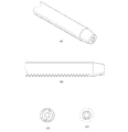
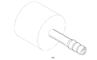
本装置の手持ち式の型の一実施形態は、例えば歯内治療に利用され、装置を把持し操作するのに使用されるハンドルと、多様な電気構成要素が収容される本体と、1つ又は複数の電極及び大地帰路を収容し、装置内の1つ又は複数の回路によって生成される音波を利用して選択された領域を洗浄するために患者の口の中で導電性液体中に差し込まれる先端部とで構成される。装置の先端部の一実施形態は、可撓性の材料で構成されことで、歯の根管内の深いところにそれを位置決めすることができる。可撓性の材料から成る先端部の一実施形態を利用することは先端部の位置決めを助けるが、当業者は、記載される結果は、可撓性ではない、すなわち剛性の材料から成る先端部でも同様に達成可能であることを認識するであろう。 One embodiment of the hand-held mold of the device is, for example, used for endodontic treatment, a handle used to grasp and operate the device, a body containing various electrical components, and one or Houses multiple electrodes and ground return and is inserted into a conductive liquid in the patient's mouth to clean selected areas using sound waves generated by one or more circuits in the device It consists of a tip. One embodiment of the tip of the device is constructed of a flexible material so that it can be positioned deep within the root canal of the tooth. While utilizing one embodiment of a tip made of a flexible material aids in positioning the tip, those skilled in the art have found that the results described are tips that are not flexible, i.e., made of a rigid material. But you will recognize that it can be achieved as well.
装置の一実施形態は、低電圧電源と、以下でより詳細に考察される装置の内部回路とを含み、これは最初の低電圧電力を高電圧電力に変換し、この高電圧電力が先端部が浸される液体に電流をパルス放出する。本方法及び装置の一実施形態の先端部は、生物学的に不活性な材料で構成された電極を利用しており、これに限定するものではないが細菌に対して毒性を有し抗病原体として作用する銀、銅、ステンレス鋼及び/又は鉄(フェライト)が含まれる。本発明の別の実施形態における電極は、セラミックベースの電極、炭素ベースの電極及び他の導電性材料を含む場合がある。電極によって形成されたナノ粒子及び/又は作用面が、根管内の細菌及び他の異物と戦う。 One embodiment of the device includes a low voltage power supply and the internal circuitry of the device, discussed in more detail below, which converts the initial low voltage power to high voltage power, which is the tip. A current is pulsed into the liquid to be immersed. The tip of one embodiment of the present method and apparatus utilizes an electrode constructed of a biologically inert material, and is not limited thereto and is toxic to bacteria and is an anti-pathogen Silver, copper, stainless steel and / or iron (ferrite) acting as The electrodes in other embodiments of the present invention may include ceramic based electrodes, carbon based electrodes and other conductive materials. Nanoparticles and / or working surfaces formed by the electrodes fight bacteria and other foreign bodies in the root canal.
本発明の一実施形態において、放電自体が、洗浄治療中と治療後の両方で異性因子を破壊するため、利用される洗浄剤は、その独自の殺菌性又は抗菌性を有する必要がない。例えばNaOCl及びEDTAがこの方法と併せて使用される場合があるが、食塩水及び水溶液もまたこの方法と共に効果的に使用される。一般に、洗浄プロトコルで利用される抗菌及び/又は殺菌流体は、誘電性の液体が放電を伝達しそれらが使用中にその効力を高めることができるため、このような装置及び方法と適合可能である。かかるに水は導電性であるため、それは本方法及び装置と共に十分に作用する。 In one embodiment of the invention, the cleaning agent utilized need not have its own bactericidal or antibacterial properties because the discharge itself destroys isomeric factors both during and after the cleaning treatment. For example, NaOCl and EDTA may be used in conjunction with this method, but saline and aqueous solutions are also effectively used with this method. In general, antibacterial and / or sterilizing fluids utilized in cleaning protocols are compatible with such devices and methods because dielectric liquids can conduct discharges and increase their effectiveness during use. . Thus, since water is conductive, it works well with the present method and apparatus.
図1〜2及び図4〜5Bの実施形態では、装置の電源は装置のハンドル内に位置しており、回路は本体内にあるが、当業者は、このような配置は、装置の人間工学性を操作する又は改善することが望まれる際、改変することができることを認識するであろう。本発明の別の実施形態は、流動電源を利用する場合もある。 In the embodiment of FIGS. 1-2 and 4-5B, the power source of the device is located in the handle of the device and the circuit is in the body, but those skilled in the art will recognize that such an arrangement is ergonomic for the device. It will be appreciated that modifications can be made when it is desired to manipulate or improve sex. Another embodiment of the present invention may utilize a fluid power source.
本装置の一実施形態の先端部における1つ又は複数の電極からの放電の利用は、洗浄流体中に「衝撃波」を形成し、これはその前面に大きな勾配を有するため、洗浄流体中に生じた圧力差が細菌膜を損傷させ、及び/又はそれらを破壊する。この波は、所与の半径において有効であるため、根管及び到達するのが困難な歯の構造に侵入し、それらを効果的に洗浄する。 Utilization of the discharge from one or more electrodes at the tip of one embodiment of the apparatus creates a “shock wave” in the cleaning fluid, which has a large gradient in front of it and thus occurs in the cleaning fluid. The differential pressure damages the bacterial membrane and / or destroys them. Because this wave is effective at a given radius, it penetrates into the root canal and tooth structures that are difficult to reach and effectively cleans them.
放電はパルス放射される衝撃波を形成し、この衝撃波は、汚染物質を細胞レベルで損傷させる。このようなパルスは、細菌及び微生物細胞を機械的に破壊し、化学的かつ永久的に細胞を変化させることでそれらは通常の生物学的な活動を止め、及び/又は細胞の遺伝系を不可逆的に変化させる。汚染物質によって被る細胞の損傷には、これに限定するものではないが細胞の内容物を放出せずに細胞壁を破ること、及び細胞壁及び細胞の内容物を分散させること、すなわちDNA破壊が含まれる。 The discharge forms a pulsed shock wave that damages contaminants at the cellular level. Such pulses mechanically destroy bacterial and microbial cells, chemically and permanently alter the cells so that they cease normal biological activities and / or irreversibly affect the cell's genetic system Change. Cell damage caused by contaminants includes, but is not limited to, breaking the cell wall without releasing the contents of the cell, and dispersing the cell wall and the contents of the cell, i.e., destroying the DNA. .
先端部のこの実施形態は付加的にUV放射を放出し、これは洗浄流体中の水分子、過酸化水素、及び考察される他の媒体及び/又は洗浄流体によって様々な度合いで吸収される際、オゾン、H2O2及びOH基を生成し、これらが微生物及びまた一部の有機化合物を破壊する。本発明の一実施形態の放電は付加的に、水和電子、ナノ粒子及び陽イオン及び/又は陰イオン(種々の実施形態において利用される金属電極から)を散布し、これらは洗浄処置が完了した後も異性因子に対して殺菌及び抗菌作用を継続する。先端部の実施形態は、以下のUV放射、水和電子、OH基、H2O2、H3O、O2、MnO2、O3(オゾン)、O、HO2、電子、正又は負イオン、反応性の化学基、ヒドロキシル基、超酸化物、ナノ粒子及び/又は他の既知の抗病原体剤、抗化学汚染物質剤、化学反応剤のうちの1つ又は複数を放出する。 This embodiment of the tip additionally emits UV radiation, which is absorbed to varying degrees by water molecules in the cleaning fluid, hydrogen peroxide, and other media and / or cleaning fluids considered. , Ozone, H 2 O 2 and OH groups, which destroy microorganisms and also some organic compounds. The discharge of one embodiment of the present invention additionally disperses hydrated electrons, nanoparticles and cations and / or anions (from the metal electrodes utilized in various embodiments), which are complete in the cleaning procedure. After that, it continues bactericidal and antibacterial action against isomeric factors. Embodiments of the tip include the following UV radiation, hydrated electrons, OH groups, H 2 O 2 , H 3 O, O 2 , MnO 2 , O 3 (ozone), O, HO 2 , electrons, positive or negative Release one or more of ions, reactive chemical groups, hydroxyl groups, superoxides, nanoparticles and / or other known anti-pathogenic agents, anti-chemical pollutants, chemical reactive agents.
本発明の実施形態の1つの利点は、それらが汚染物質に対して効果的であり、さらに相対的に短い期間にわたって比較的低い電力環境を利用し、高レベルの効率を達成することができる点である。特に低い電力環境を使用する本発明の実施形態によって駆動回路の小型化及び電力要件の簡素化が可能になる。例えば、本発明の一実施形態は、25秒から5分間で20Hzの間で、すなわち26マイクロジュール〜4ジュールのエネルギーで選択された媒体から異性因子を撲滅する。本発明の一部の実施形態は、先の例より少なくとも3等級低い電力要件を利用する、すなわちジュールの代わりにマイクロモジュールを利用する。このような環境は、装置の使用及び装置の実施形態による一例であり、電極環境及び治療の期間は変化する。 One advantage of embodiments of the present invention is that they are effective against pollutants and can utilize a relatively low power environment over a relatively short period of time to achieve a high level of efficiency. It is. Embodiments of the present invention that use a particularly low power environment allow miniaturization of the drive circuit and simplification of power requirements. For example, one embodiment of the present invention eliminates isomeric factors from a selected medium between 20 Hz in 25 seconds to 5 minutes, i.e. with an energy of 26 microjoules to 4 joules. Some embodiments of the present invention utilize power requirements that are at least three grades lower than the previous example, ie, use micromodules instead of joules. Such an environment is an example according to the use of the device and the embodiment of the device, the electrode environment and the duration of treatment vary.
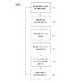
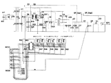
図1及び図1Aは、本装置100,1800の一実施形態を描いている。簡素化するために、これら実施形態の要素は、ブラックボックスとして描かれている。当業者は、それぞれの説明から構成要素を認識するであろう。また、これより後の図面、例えば図2は、個々の構成要素の視覚的な外観に関するより詳細な図面を提供している。
1 and 1A depict one embodiment of the
図1及び図1Aの実施形態において、電源、すなわち蓄電池101,1801が、ハンドピース筐体(描かれていない)内に収容されている。図1では中心電極115、大地帰路電極116及び下部電極組立体117が、先端部内に又は先端部に配置されており、この下部電極組立体117が先端部の一部が沈められる液体と接触することで液体中に音波を形成する。図1Aにおいて、高電圧放電中心電極1815、高電圧放電接地電極1816及び下部大地帰路電極組立体1817が、先端部内に又は先端部に配置されており、この下部大地帰路電極組立体1817が先端部の一部が沈められる液体と接触することで液体中に音波を形成する。図6〜図6Fを参照して後に説明するように、先端部は正極及び負極並びに/あるいは大地帰路を収容する。先端部のこの実施形態における電極の間隔は、先端部の機能の一因となり得る。例えば異なる実施形態は、放電特性(電力、時間及び電力曲線の形状)と、放電を認める流体を含めた導電性媒体と、電極/接地組立体の表面積との間に均衡を与える。
In the embodiment of FIGS. 1 and 1A, a power source, i.e.,
まず、図1を参照すると、筐体(描かれていない)は、電子回路及び他の壊れやすい電気充電式の要素を取り囲んでいる。本発明のいくつかの実施形態において、筐体は、装置が操作者のむき出しの手又は最小限に保護された手に保持されるので電気を伝えない材料でできている。筐体を形成するのに使用される材料には、これに限定するものではないがプラスチック、木、ガラス繊維、金属及び/又は複合材料が含まれる。本発明の一実施形態におけるプラスチック筐体の利用は、製造コストの削減を表している。本発明の別の実施形態では、筐体は導電性であり、大地帰路として機能する。筐体は、筐体の内側の蓄電池区画(描かれていない)内に蓄電池101を交換しやすくするための開口を含む。筐体はまた、清掃しやすく、1つ又は複数の蓄電池101を交換しやすくするように成型され、かつ操作者によって保持され操作されるように人間工学的に設計される。
Referring first to FIG. 1, a housing (not shown) surrounds electronic circuitry and other fragile electrically rechargeable elements. In some embodiments of the invention, the housing is made of a material that does not conduct electricity because the device is held in the operator's bare or minimally protected hands. Materials used to form the housing include, but are not limited to, plastic, wood, glass fiber, metal and / or composite materials. The use of a plastic housing in one embodiment of the present invention represents a reduction in manufacturing costs. In another embodiment of the present invention, the housing is conductive and functions as a ground return. The housing includes an opening for facilitating
当業者は、1つ又は複数の蓄電池101が単にこのようなデバイスのための多くの電源選択肢の1つであることを理解するであろう。例えば、本発明の別の実施形態は、電源として太陽電池を利用する。図1において、1つ又は複数の蓄電池101は、本実施形態のその後の構成要素によって、後により高い電圧に変換される低電圧電源として機能する。この装置の実施形態において利用される蓄電池101には、これに限定するものではないがイオンリチウム電池などのリチウム電池が含まれる。本発明の一部の実施形態において、リチウム電池は、それらが高い電流と、迅速な充電時間を有することが理由で利用されている。付加的にリチウムイオン電池は、そのサイズにしては高いエネルギー貯蔵密度を有し、これは、装置が小さくなるほど、操作者がそれを利用しやすくなるため本発明の実施形態において有利である。付加的にリチウムイオン電池は、そのサイズにしては高いエネルギー密度を有するため、メモリ問題がなく、迅速に充電することができるため電流を効率的に放出する。当業者は、リチウム及びリチウムイオン電池は本発明の一部の実施形態に適合可能であるが、本装置の実施形態によって利用される電源の一例にすぎないことを理解するであろう。
One skilled in the art will appreciate that the battery or
低電圧電源を利用し、後に低電圧電源を高電圧電源に変換することによって、例えば蓄電池などの容易に利用可能な電源を利用するといった利点を提供する。記載される実施形態は、低電圧電源をデバイスによって利用される高電圧に変換するための構成要素を含む。しかしながら当業者は、本発明の別の実施形態は、利用される電源に応じて、これに限定するものではないがキャビテーションプロセス、キャビテーション生成物、UV光、水和電子、OH基、H2O2、H3O、O2、MnO2、O3(オゾン)、O、HO2、電子、正又は負イオン、反応性の化学基、ヒドロキシル基、超酸化物、ナノ粒子及び/又は他の既知の抗病原体剤、抗化学汚染物質剤、化学反応剤を含めた所望されるものを形成する際に利用できる特定の電圧を達成する及び/又は維持する目的で、一貫した電圧を維持する及び/又は電源によって提供された電圧を下げるように構成され得ることを理解するであろう。 By using a low-voltage power supply and later converting the low-voltage power supply to a high-voltage power supply, the advantage of using an easily available power supply such as a storage battery is provided. The described embodiments include components for converting a low voltage power supply to a high voltage utilized by the device. However, those skilled in the art will appreciate that other embodiments of the present invention may include, but are not limited to, cavitation processes, cavitation products, UV light, hydrated electrons, OH groups, H 2 O, depending on the power source utilized. 2 , H 3 O, O 2 , MnO 2 , O 3 (ozone), O, HO 2 , electrons, positive or negative ions, reactive chemical groups, hydroxyl groups, superoxides, nanoparticles and / or other Maintaining a consistent voltage for the purpose of achieving and / or maintaining a specific voltage that can be utilized in forming a desired one, including known anti-pathogenic agents, anti-chemical pollutants, chemical reactants; and It will be appreciated that / or can be configured to reduce the voltage provided by the power source.
蓄電池以外の低電圧電源が別の実施形態と併せて使用される。例えば卓上式の本発明の別の実施形態は、電線を利用してハンドピースを電源及びボックスに接続する。この実施形態は、標準的な電源コードを利用して、これに限定するものではないが110Vから220ac50/60Hzを含めた電力を供給する。本発明の種々の実施形態は、AC、DC及び/又は他の電流並びに世界中で使用される電力を利用するように構成される。 A low voltage power supply other than a storage battery is used in conjunction with another embodiment. For example, another embodiment of the table-top type of the present invention utilizes a wire to connect the handpiece to a power source and box. This embodiment utilizes standard power cords to provide power including but not limited to 110V to 220ac50 / 60Hz. Various embodiments of the present invention are configured to utilize AC, DC and / or other currents and power used throughout the world.
蓄電池区画及び筐体によって、1つ又は複数の蓄電池101を交換しやすくすることが可能になる。したがって電源のメンテナンスが簡素化される。蓄電池区画に収容され装置に電力を与える1つ及び/又は複数の蓄電池101には、これに限定するものではないが0.8vdc〜30vdc、及び/又は3〜7ボルト蓄電池が含まれる。
One or
DC低電圧調整器102が内部の蓄電池区画を備えた筐体に結合され、これは装置のこの実施形態において電子構成要素及び集積回路における機能を調整する。低電圧調整器102には、金属−酸化物半導体電界効果トランジスタ(MOSFET)110に動力を提供するDC電圧スイッチング集積回路(IC)駆動装置103、及び0.8vdc〜30vdc及び/又は3から7ボルトの蓄電池入力をこれに限定するものではないが180vdc〜300vdcを含めたバス電圧に変換する高電圧スイッチング変圧器104が結合される。高電圧スイッチング変圧器104は、これに限定するものではないが高周波数フェライト磁心変圧器が含まれる。
A DC low voltage regulator 102 is coupled to a housing with an internal battery compartment, which coordinates functions in the electronic components and integrated circuits in this embodiment of the device. The low voltage regulator 102 includes a DC voltage switching integrated circuit (IC)
この実施形態において、フェライト磁心変圧器は、それが高い周波数を有し、小型であり、極めて効率的であり、高い電流を扱うことができるために利用されている。サイズが小さいことは、デバイスの手持ち式の実施形態において人間工学的に有利である。高い電流の許容性により、フェライト磁心変圧器が、フォトフラッシュ蓄積コンデンサなどの高電圧放電蓄積コンデンサフィルタ107を迅速に充電することが可能になる。装置内に生成される音響パルスは高速かつ反復的であるため、よってその作動において迅速な充電が望ましい。本発明の別の実施形態は、フェライト磁心変圧器に関して挙げられる1つ又は複数の利点を有する種々の変圧器を利用する。本発明の別の実施形態は、同様の電気特性を有する種々のコンデンサを利用する。
In this embodiment, a ferrite core transformer is utilized because it has a high frequency, is small, extremely efficient, and can handle high currents. The small size is ergonomically advantageous in the handheld embodiment of the device. High current tolerance allows a ferrite core transformer to quickly charge a high voltage discharge
本実施形態において、変換後の300vdc電圧が、液体溶液中で音響衝撃波を推進させ、これが、歯内治療における洗浄を含めた洗浄に利用される所望される音響効果を生み出す。本発明の別の実施形態は、例えば蓄電池などの電源からの低い電圧をより高い電圧の電力に、例えば250vdc〜500vdcの電力に変換する。本発明の別の実施形態は、180vdc〜250vdcまで電圧を変換する。電圧の大きさは、関連する実施形態の用途に応じて変化する。 In this embodiment, the converted 300 vdc voltage drives an acoustic shock wave in the liquid solution, which produces the desired acoustic effect utilized for cleaning, including cleaning in endodontic treatment. Another embodiment of the present invention converts a low voltage from a power source, such as a storage battery, to a higher voltage power, for example from 250 vdc to 500 vdc. Another embodiment of the present invention converts the voltage from 180 vdc to 250 vdc. The magnitude of the voltage varies depending on the application of the related embodiment.
ブリッジ整流器105が、高電圧スイッチング変圧器104に結合され、高電圧スイッチング変圧器104のAC出力を変換する。その後高電圧フィルタインダクタ106が、高電圧放電蓄積コンデンサフィルタが適切に作動するようにACリップル電流を取り除く。
A
本発明の一実施形態において、フォトフラッシュ蓄積コンデンサが、高電圧放電蓄積コンデンサフィルタ107として使用されるが、これはフォトフラッシュ蓄積コンデンサが低インピーダンスを有し、過熱したり故障したりせずに、すなわちその電気特性に損傷を招くことなく複数の反復する放電に耐えることが可能であるためである。別の実施形態は、低インピーダンスを有する異なる高電圧エネルギー蓄積コンデンサ及び/又はコンデンサバンクを利用する。当業者は、上記に挙げた特性を有する他のコンデンサがフォトフラッシュ蓄積コンデンサに勝ることを理解するであろう。本発明の実施形態は、このような特性を有する1つ又は複数のコンデンサを利用する場合がある。複数のコンデンサが利用される場合、それらは同一である又は異なる種類の場合がある。単一のコンデンサを利用する本発明の実施形態は、これに限定するものではないが小型化し易い、ノイズが抑えられる及び設計が簡素化されることを含めた利点を提供する。
In one embodiment of the present invention, a photoflash storage capacitor is used as the high voltage discharge
高電圧放電蓄積コンデンサフィルタ107が高放電負荷インダクタ108に結合されることで、高放電負荷インダクタ108が、高い放電電流の下で低インピーダンスから高インピーダンスに飽和し、これにより回路のスイッチング出力部を隔絶する。
The high voltage discharge
このような隔絶が達成された後、高電圧放電点火器コンデンサ109が全てのエネルギーを高電圧放電点火器変圧器114へと放出し、一部の実施形態では高電圧パルス、あるいは他の実施形態ではより低電圧のパルス、例えば250V未満のパルスを含み得るパルスを発生させ、これを利用して液体を攪拌し洗浄及び消毒に利用される音波を形成する。この実施形態において、MOSFET110は電圧放電点火器コンデンサ109を高電圧放電点火器変圧器114へと放電させる。本発明の別の実施形態は追加のトランジスタを利用し、これに限定するものではないがシリコン制御整流器(SCR)トランジスタが含まれる。
After such isolation is achieved, the high voltage
MOSFET110の作用は、マイクロコントローラデバイス118によって制御される。MOSFET110の作用に加えて、マイクロコントローラデバイス118は、装置のこの実施形態における機能を制御し、これに限定するものではないが周期時間、サイクル時間(Hz)及び回路の出力部の電流が含まれる。パルス時間は、蓄積されたエネルギーの1つの機能であり、これは本実施形態ではマイクロ秒で表示される。マイクロコントローラデバイス118を利用して電流を設定することによって、電池残量が本実施形態において温存される。
The operation of
高電圧放電点火器コンデンサ109によってエネルギーが放出されると、高電圧放電点火器変圧器114は高電圧パルスを形成する。高電圧パルスが、エアスパークギャップと液体溶液を分断することで、高電圧放電点火器コンデンサ109は、全てのそのエネルギーを放出することができる。高電圧放電点火器変圧器114は、高電圧ブロックコンデンサ113によって隔絶される。上記に述べたように、高電圧放電点火器変圧器114は、低インピーダンスデバイスであり、高電圧放電蓄積フィルタ107内に放電され蓄積される高い電流によって損傷を受ける。図1の実施形態は、電気ギャップとしてスパークギャップを含むが、本発明の別の実施形態はこの構成要素を利用しない。
When energy is released by the high voltage
本実施形態において、スパークギャップ112は、高電圧スイッチとして機能する。スパークギャップ112は、高電圧電源及び高電圧放電蓄積フィルタ107内に蓄積されたエネルギーを隔絶する。装置の先端部が浸される液体溶液は、誘電性であるため、スパークギャップ112なしで液体中で行われる充電は、回路の出力部に負荷をかける。本実施形態では、スパークギャップ112によって、高電圧出力部が完全に充電することで高い電流の放出を達成することが可能になる。高電圧放電点火器変圧器114によって形成される高電圧パルスが、エアスパークギャップと液体溶液を分断し、高電圧放電点火器コンデンサ109がその全てのエネルギーを放出することを可能にし、このスパークギャップ112を高電圧スイッチにする。
In the present embodiment, the
装置の先端部は、随意選択で交換可能であり、図6〜図6Fを参照してより詳細に考察する。しかしながらこの先端部の構成要素は図1において描かれている。 The tip of the device is optionally interchangeable and will be discussed in more detail with reference to FIGS. However, the tip components are depicted in FIG.
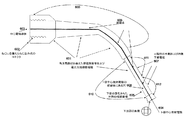
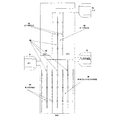
図1を参照すると、先端部は、本発明の一実施形態において高電圧放電正極である中心電極115と、本発明の一実施形態において高電圧放電負極である大地帰路電極116と、発射室(描かれていない)を備える下部電極組立体117とを含む。中心電極115は、先端部の一部の実施形態におけるその位置によりそのように呼ばれており、先端部に埋め込まれており、大地帰路電極116は、先端部の外側に位置しており、これに限定するものではないが先端部の外側の覆い上に位置している。先端部の下部において、先端部にある電極を取り囲む導電性の筐体(描かれていない)と、先端部の中にある絶縁体(描かれていない)の両方にある穴によって液体溶液が発射室(描かれていない)へと進入することが可能になる。発射室は、下部電極組立体117を含む。これは、放電が行われる場所である。先端部にある下部電極組立体117が液体中に置かれることで、液体を攪拌し、目標とする領域の洗浄に利用される音波を形成する。
Referring to FIG. 1, the tip includes a
本発明の一実施形態において、中心電極115は負極であり、大地帰路電極116は正極である。パルスを生成するために異なる電荷を有する中心電極と帰路電極があるという条件で電極の電荷は変化する。装置は、中心電極115と、大地帰路電極116とを利用して放電を形成するが、これらは図6を参照してより詳細に考察される。
In one embodiment of the present invention, the
上記で述べたマイクロコントローラデバイス118には、液晶ディスプレイ(LCD)119が結合され、ユーザが装置を正確に利用するのを助ける。この実施形態はプログラム可能であるため、LCD119は選択された環境をユーザに表示する。
Coupled to the microcontroller device 118 described above is a liquid crystal display (LCD) 119 that helps the user to use the device correctly. Since this embodiment is programmable, the
本発明の別の実施形態は、異なるディスプレイを利用し、一部の実施形態は、ディスプレイはユーザフレンドリーであるが、装置のコストに影響を及ぼす可能性があるためディスプレイを利用しない。マイクロコントローラデバイス118に結合された開始/停止スイッチ120が装置を開始させ停止させる。第2のスイッチ、すなわち周期サイクルパルス時間選択スイッチ121によってユーザが周期時間及びサイクル時間を選択することが可能になる。本発明の別の実施形態において、LCDディスプレイ119、又は代替のディスプレイは、開始/停止スイッチ120及び周期サイクルパルス時間選択スイッチ121と同じ機能を含む開始/停止及び/又は選択制御装置を備えたタッチスクリーンと一体化される。またマイクロコントローラ118には、プログラム可能な電流制御トリムポット122が結合され、これはマイクロコントローラデバイス118とDC電圧スイッチングIC駆動装置103を接続するのに使用される。
Another embodiment of the present invention utilizes a different display and some embodiments do not utilize a display because the display is user friendly but may affect the cost of the device. A start /
図1を参照して考察したように、本発明の別の実施形態はスパークギャップを利用しない。図1Aは、この構成要素を利用しない一実施形態の一例である。 As discussed with reference to FIG. 1, another embodiment of the present invention does not utilize a spark gap. FIG. 1A is an example of one embodiment that does not utilize this component.
図1Aを参照すると、筐体(描かれていない)が、電子回路及び他の壊れやすい帯電製品を取り囲んでいる。本発明の一部の実施形態において、筐体は、オペレータの裸の又は最小限に保護された手の中に保持されるため電気を伝えない材料で作成される。図1の実施形態でのように、筐体を形成するのに使用される材料には、これに限定するものではないがプラスチック、木、ガラス繊維、金属及び/又は複合材料が含まれ、筐体は、筐体の内側の蓄電池区画(描かれていない)内に蓄電池1801を交換し易くするための開口を含む。当業者は、1つ又は複数の蓄電池1801はこのデバイスのための多くの電源オプションの1つにすぎないことを認識するであろう。本装置の実施形態で利用される蓄電池1801には、これに限定するものではないがリチウムイオン電池などのリチウム電池が含まれる。本発明の一部の実施形態において、リチウム電池は、高い電流と、迅速な充電時間を有することから利用される。装置に電力を供給するために蓄電池区画内に収容される1つ又は複数の蓄電池101には、これに限定するものではないが0.8vdc〜30vdcの電圧範囲を有する電池が含まれる。
Referring to FIG. 1A, a housing (not shown) surrounds electronic circuitry and other fragile charged products. In some embodiments of the invention, the housing is made of a material that does not conduct electricity because it is held in the operator's bare or minimally protected hands. As in the embodiment of FIG. 1, the materials used to form the housing include, but are not limited to, plastic, wood, glass fiber, metal and / or composite materials. body includes an opening for facilitating the
図1Aを参照すると、蓄電池1801からの電圧は低電圧調整器1802へ流れ、この調整器が電圧を全ての集積回路及びマイクロプロセッサに対して調整する。スイッチングIC駆動装置1803が蓄電池1801から調整されない電圧を受け取り、スイッチングIC駆動装置1803が高電圧スイッチング変圧器1804と連動してAC電圧をDCブリッジ整流器1805へと送りブリッジ整流器がAC高電圧をDCに変換する。このDC高電圧は、インダクタ1806を通って流れ、インダクタがいかなるリップル電流も取り除く。インダクタ1806を通過した後、電圧は高電圧フィルタコンデンサ1807(このコンデンサもまた高電圧蓄積バンクである)へと流れ、高電圧放電コンデンサを迅速に充填する。
Referring to FIG. 1A, the voltage from the
高電圧フィルタコンデンサ1807は次に高電圧放電負荷インダクタ1808へと流れ、このインダクダは本発明の一実施形態において飽和式インダクタである。電圧はその後高電圧放電負荷インダクタ1808から高電圧放電コンデンサ1809へと流れ、この高電圧放電コンデンサは、ハイサイドローサイド金属酸化膜半導体電界効果トランジスタ(MOSFET)1810bに接続される(MOSFETは一般に、この呼び名は重複しているにも関わらずMOSFETトランジスタと呼ばれる)。
The high
マイクロコントローラデバイス1818は、これに限定するものではないが開始と停止、処理時間、サイクル時間、Hz周波数及びパルス時間を含めた機能を制御する。マイクロコントローラデバイス1818はまた、液晶ディスプレイ(LCD)1819及びプログラム可能なトリムポット1822も制御する。この実施形態において、LCD1819は、ユーザが装置を正確に利用するのを助ける。この実施形態はプログラム可能であるため、LCD1819は選択された環境をユーザに対して表示する。図1Aの1つ又は複数の態様を採用する本発明の別の実施形態は、様々なディスプレイを利用し、ディスプレイはユーザフレンドリーであるが、装置のコストに影響を与える場合があるためディスプレイを利用しないものもある。この実施形態では、プログラム可能なトリムポット1822はバス電圧を制御する。
図1Aに戻ると、この実施形態では、マイクロコントローラ1818が、ハイサイド及びローサイドMOSFET駆動装置1810aに信号を送信し、このMOSFET駆動装置は、ハイサイド及びローサイドMOSFETトランジスタ1810bに接続されている。そしてハイサイドMOSFETトランジスタ1810bは、高電圧放電コンデンサ1809に接続される。
Returning to FIG. 1A, in this embodiment, the
上記に述べたように、高電圧放電中心電極1815、高電圧放電接地電極1816及び下部大地帰路電極組立体1817は、この実施形態の先端部を構成する。理解し易くするために、高電圧放電中心電極1815、高電圧放電接地電極1816及び下部大地帰路電極組立体1817は、先端部組立体としてひとまとめに呼ぶことにする。
As described above, the high-voltage
図1Aに戻ると、高電圧放電中心電極1815は、MOSFETトランジスタ1810bのハイサイドに結合される。高電圧放電コンデンサ1809内に蓄積された高電圧が、マイクロコントローラデバイス1818のコマンドで高電圧放電中心電極1815に送られる。この信号が送信される際、高電圧ハイサイドMOSFET1810bが電気を伝え、電流/電圧が高電圧放電中心電極1815へと下方に流れる。電圧は高電圧放電中心電極1815へと下方に流れ、そこで例えば誘電性溶液などの導電性の溶液と接触する。電流はこの液体溶液中を流れ、高電圧放電大地帰路電極1816及び下部大地帰路電極組立体1817を通る回路経路を完成させる。
Returning to FIG. 1A, the high voltage
本発明の一実施形態では、下部大地帰路電極組立体1817によって液体溶液が組立体の底部における排出口(描かれない)を通って発射室に侵入することが可能になる。先端部組立体が誘電性の液体溶液中に浸される際、回路は、高電圧放電中心電極1815を通る高電圧パルスを送り、高電圧電流が液体溶液中を流れ、液体溶液中に放電を生じさせる。このような放電によって、キャビテーション衝撃波が生じ、回路経路を完成させる。
In one embodiment of the present invention, the lower earth
図1Aの実施形態において、ハイサイドローサイドMOSFET1810bは、高電圧放電コンデンサ1809からの電流/電圧を高電圧放電中心電極1815へと下方に伝える役割を担っている。これらの機能には、電子信号の増幅及び/又は切り換え作業の1つ又は複数が伴う。この実施形態におけるハイサイドローサイドMOSFETの利用は、この機能を果たすために利用され得る電気構成要素の一例である。当業者は、同様の機能を達成するために、追加の電気構成要素が1つ又は複数のハイサイドローサイドMOSFETの代わりをする、及び/又は1つ又は複数のハイサイドローサイドMOSFETと組み合わされることもあることを認識するであろう。ハイサイドローサイドMOSFET1810bに属する機能を実行するために本発明の種々の実施形態に含まれる電気構成要素には、これに限定するものではないが絶縁ゲートバイポーラトランジスタ(IGBT)、シリコン制御整流器(SCR)、バイポーラトランジスタ(NPN及びPNPを含む)及びダーリントントランジスタが含まれる。
In the embodiment of FIG. 1A, the high-side low-
等価な機能を達成する代替の構成要素の代わりに、本発明の実施形態におけるハイサイドローサイドMOSFETを利用することで、特定の有利な電気特性をデバイスの構造に取り込むことができる。MOSFETを利用する利点には、これに限定するものではないがロスを制限すること(MOSFETは、等価な機能と備えた構成要素と比べてそれほどロスが大きくない)及び低インピーダンスの構成要素を提供することが含まれる。 By utilizing the high-side low-side MOSFET in the embodiments of the present invention instead of alternative components that achieve equivalent functions, certain advantageous electrical characteristics can be incorporated into the device structure. Advantages of using MOSFETs include, but are not limited to, limiting loss (MOSFETs are not as lossy as components with equivalent functions) and low impedance components For example.
図1Aに戻ると、当業者によって認識されるように、図1Aと同等の実施形態において1つ又は複数のハイサイド及びローサイドMOSFET1810aの代わりに、あるいはそれと併せて、高電圧放電コンデンサ1809から電流/電圧を高電圧放電中心電極1815へと下方に伝えるのに利用される電気構成要素は、ハイサイド及びローサイドMOSFET駆動装置1810aの代わりに代替の駆動装置を利用する場合がある。
Returning to FIG. 1A, as will be appreciated by those skilled in the art, a current / current from the high
図2は、装置200の別の実施形態である。図1の実施形態と同様に、図2はスパークギャップを利用する。図2は、装置の形状及び人間工学的な設計を反映するように設計されている。この実施形態は手持ち式であるためハンドピース筐体201は掴みやすく、装置の実施形態はユーザによって容易に操作される。装置200の一端には、交換可能な先端部210があり、この実施形態は図6〜図6Fを参照してさらに考察される。
FIG. 2 is another embodiment of the
図1の実施形態と同様に図2のハンドピース筐体201は、例えばプラスチックなどの非導電性材料で成型されており、ハンドピース筐体201はまた、清掃しやすく、中の蓄電池202を容易に交換できるように成型されている。本発明の別の実施形態において、筐体は導電性であり、大地帰路として機能する。プラスチックを利用する実施形態、すなわち非導電性の筐体は製造コストを抑えることができる。
Similar to the embodiment of FIG. 1, the
この実施形態では蓄電池202のための2つの区画が、非制限的な例として示されている。選択される蓄電池によって、装置によって生成される音響パルスを実現するために使用される数は変化する。本実施形態において利用される蓄電池202には、これに限定するものではないが0.8vdc〜30vdc電池、及び/又は180vdc 3〜7ボルト電池が含まれる。蓄電池202の低い電圧は、図1の実施形態でのようにこの実施形態において追加の構成要素によって後に増大され、例えば歯内洗浄において利用される音響作用を生む音響衝撃波を液体溶液中で駆動する。
In this embodiment, two compartments for the
蓄電池202は、電力接地204を備えた低電圧DC電源205を充電する。タイミング回路206が低電圧DC電源205から入力を取得し、また開始/停止スイッチ203から入力を取得する。ユーザによる開始/停止スイッチ203の作動が、装置が動作可能であるかどうかを制御する。このタイミング回路206は、高電圧点火器スイッチ回路209に電力を供給する。装置200のこの実施形態において、開始/停止スイッチ203は実施形態の作動を制御する。
The
この実施形態200において、高電圧点火器スイッチ回路209がスパークギャップスイッチ208に結合される。スパークギャップスイッチ208には高電圧DC電源207も結合される。低電圧DC電源205はタイミング回路206に入力し、これが高電圧DC電源207に入力する。
In this
図1Aと同様に、図2Aの実施形態は、スパークギャップ又は点火器を利用しない。しかしながら図1Aの実施形態と同様に、図2Aのハンドピース筐体201は、プラスチックなどの非導電性材料で成型され、ハンドピース筐体201はまた、清掃し易く、中の蓄電池202を交換し易くすることができるように成型される。本発明の別の実施形態では、筐体は導電性であり、大地帰路として機能する。プラスチックを利用する実施形態、すなわち非導電性の筐体は、製造コストを下げることができる。
Similar to FIG. 1A, the embodiment of FIG. 2A does not utilize a spark gap or igniter. However, similar to the embodiment of FIG. 1A, the
図2Aに戻ると、この実施形態における蓄電池202のための2つの区画は非制限的な例として示される。選択される蓄電池によって、装置によって生成される音響パルスを達成する(及びキャビテーションを制御する)のに使用される数は変化する。この実施形態において利用される蓄電池202には、これに限定するものではないが0.8vdc〜30vdcの蓄電池及び/又は180vdc 3〜7ボルトの蓄電池が含まれる。本発明の種々の実施形態において、蓄電池はリチウムであり、電圧の範囲は、3.6V〜7.4Vである。蓄電池202の低電圧は、実施形態において追加の構成要素によって後に拡大され、図1Aの実施形態でのように、例えば歯内洗浄で利用される音響作用を生む音響衝撃波を液体溶液中に推し進める。
Returning to FIG. 2A, the two compartments for the
図2Aの実施形態において、蓄電池202は、電圧及び電流を出力して回路を作動させる。電圧が蓄電池202から低電圧電源204へと流れ、この低電圧電源が電力を全ての集積回路及びタイミング回路206に対して調整する。電圧は低電圧電源204から高電圧電源207へと進み、この高電圧電源が蓄電池202からの電圧を高電圧に変換する。例えば本発明の種々の実施形態において、電圧は全ての160ボルトのDCから300ボルトDCの高さに、又はこれより高い高さに変換させることができる。
In the embodiment of FIG. 2A, the
図2Aの実施形態において、タイミング回路206はマイクロコントローラデバイスである。LCDディスプレイ又は代替のディスプレイを利用する実施形態では、タイミング回路206がこのディスプレイを制御する。図2Aの実施形態では、タイミング回路206は、開始停止スイッチ203、周期時間、サイクル時間、パルス幅時間を制御し、この実施形態で利用される場合、開始停止スイッチ203はまた、バス電圧を制御する電子トリムポットを制御する。
In the embodiment of FIG. 2A,
高電圧放電コンデンサ208は、これに限定するものではないがハイサイドローサイドMOSFETを含めたトランジスタ又は制御された整流器209に接続され、高電圧放電コンデンサ208が電力をジュールで出力する。ハイトランジスタ又は制御された整流器(例えばハイサイドローサイドMOSFET及び駆動回路)209は、タイミング回路206によって制御される。理解し易くするために、図2Aでは、トランジスタ又は制御された整流器は、単一の要素で描かれるが、本発明の実施形態では、この要素が、これに限定するものではないがハイサイドローサイドMOSFET及び駆動回路を含む場合がある。トランジスタ又は制御された整流器209において、タイミング回路206は、トランジスタ又は制御された整流器を制御する。ハイサイドローサイドMOSFET及びMOSFET駆動装置を利用する実施形態では、タイミング回路206が駆動回路を制御し、この駆動回路はMOSFETに接続される。タイミング回路206がデバイスに信号を送信する際、高電圧放電コンデンサ208は、エネルギーを先端部組立体に出力する。エネルギーは、交換式の先端部210において放出され、これが交換式の先端部210が少なくとも部分的に沈められる液体中に音響衝撃波を形成する。
The high
当業者は、本発明の別の実施形態において、ハイサイドローサイドMOSFET及び駆動回路が1つ又は複数のハイサイドローサイドMOSFETとして及び/又はそれと組み合わせて利用される実施形態において、追加の電気構成要素が1つ又は複数のハイサイドローサイドMOSFETに置換えられることで、高電圧放電コンデンサ208から交換式の先端部210へと電力を供給する場合もあることを認識するであろう。このような機能を実行するために本発明の種々の実施形態に含まれる電気構成要素には、これに限定するものではないがトランジスタ、制御された整流器、絶縁ゲートバイポーラトランジスタ(IGBT)、シリコン制御整流器(SCR)、バイポーラトランジスタ(NPN及びPNPを含む)及びダーリントントランジスタが含まれる。
One skilled in the art will recognize that, in another embodiment of the present invention, in an embodiment where the high-side low-side MOSFET and drive circuit are utilized as and / or in combination with one or more high-side low-side MOSFETs, the additional electrical components are It will be appreciated that one or more high side low side MOSFETs may be replaced to supply power from the high
図3は、図1及び図5の実施形態のように点火器を利用する本発明の一態様の全体のワークフロー300である。図3を通して、簡素化するために図2の要素が参照される。しかしながら図2は、装置の一実施形態にすぎない。ワークフロー300は装置の別の実施形態にも適用可能である。図3の後に考察される図3Aは、スパークギャップ及び/又は点火器を利用しない図1Aの実施形態などの実施形態に関するワークフローである。
FIG. 3 is an
図3を参照すると、1つ又は複数の蓄電池202が、電圧及び電流を供給して回路を作動する(310)。図2では手持ち式デバイスに適合するのに十分に小さい低電圧DC電源205及びタイミング回路420が低電圧を高電流/電圧に変換する(320)。高電圧点火器スイッチ回路209が、電流が低い極めて鋭い高電圧スパイクを生成する(330)。高電圧スパイクはこの構成要素を利用する一実施形態においてエアギャップスイッチ208を切断する(340)、及び/又はMOSFETハイサイド及びローサイドを直接利用して投入される。スパークがエアギャップを埋める際、この隙間は導電性になり、それによって蓄積された全てのエネルギーを完全に放出することが可能になる(350)。本発明の種々の実施形態において、このエネルギーは図1における高電圧コンデンサ109のようなコンデンサに蓄積される。
Referring to FIG. 3, one or
蓄積されたエネルギーが放出される際、装置210先端部の先端部は液体溶液中にあり、先端部210を貫通して進むエネルギーが液体中に音響衝撃波を形成する(360)。波がひとたび形成されると、工程は蓄電池202が継続して電圧を回路に供給するので繰り返される(310)。
When the stored energy is released, the tip of the
本発明の一実施形態において、図3(及び図1について説明される)において実現される放電は、細菌などの異性因子と戦うためにただ単に音波を出力するだけではない。(350)における放電は、上記に挙げた音響衝撃波、液体媒体中のキャビテーション、UV照射、水和電子、OH基、H2O2、ナノ粒子及び正又は負イオン(図6で後に考察される、先端部において金属電極を利用する本発明の実施形態の)を出力する。この実施形態は、以下のUV照射、水和電子、OH基、H2O2、H3O、O2、MnO2、O3(オゾン)、O、HO2、電子、正又は負イオン、反応性の化学基、ヒドロキシル基、超酸化物、ナノ粒子及び/又は他の既知の抗病原体剤、抗化学汚染物質剤、化学反応剤の1つ又は複数を出力することができる。 In one embodiment of the present invention, the discharge realized in FIG. 3 (and described with respect to FIG. 1) does not simply output a sound wave to combat isomeric factors such as bacteria. The discharge in ( 350) is the acoustic shock wave listed above, cavitation in liquid media, UV irradiation, hydrated electrons, OH groups, H 2 O 2 , nanoparticles and positive or negative ions (discussed later in FIG. 6). Of the embodiment of the present invention utilizing a metal electrode at the tip. This embodiment includes the following UV irradiation, hydrated electrons, OH groups, H 2 O 2 , H 3 O, O 2 , MnO 2 , O 3 (ozone), O, HO 2 , electrons, positive or negative ions, One or more of reactive chemical groups, hydroxyl groups, superoxide, nanoparticles and / or other known anti-pathogenic agents, anti-chemical pollutants, chemical reactive agents can be output.
図3Aは、図1A及び図2Aと同様の回路を利用する、すなわち点火器もスパークギャップもない本発明の一実施形態の一例のワークフローである。このワークフローでは、本発明の一実施形態において、蓄電池(又は代替の電源)が電圧及び電流を出力し回路を作動させる(310)。回路は蓄電池からの低電圧をより高い電圧に変換する(320)。このときより高くなったこの電圧がコンデンサに送られ(330)、コンデンサからハイサイドローサイドMOSFETへと送られる(340)。MOSFETハイサイドにスイッチが入り、エネルギーが先端部において放出されると(350)、先端部が液体中に音響衝撃波を形成する(360)。 FIG. 3A is an example workflow of an embodiment of the present invention that utilizes a circuit similar to that of FIGS. 1A and 2A, ie, no igniter and no spark gap. In this workflow, in one embodiment of the present invention, a storage battery (or alternative power source) outputs voltage and current to activate the circuit ( 310). The circuit converts the low voltage from the battery to a higher voltage ( 320). This higher voltage is then sent to the capacitor ( 330) and from the capacitor to the high side low side MOSFET ( 340). When the MOSFET is turned on and the energy is released at the tip ( 350), the tip forms an acoustic shock wave in the liquid ( 360).
本発明の一実施形態において、図3Aにおいて(及び図1Aを参照して記載した)達成される放電は、例えば細菌などの異性因子と戦う単なる音波を出力するだけではない。(350)における放電は、上記に挙げた音響衝撃波、液体媒体中のキャビテーション、UV照射、水和電子、OH基、H2O2、H3O、O2、MnO2、O3(オゾン)、O、HO2、電子、正又は負イオン(図6で後に考察される、先端部において金属電極を利用する本発明の実施形態の)、反応性の化学基、ヒドロキシル基、超酸化物、ナノ粒子及び/又は他の既知の抗病原体剤、抗化学汚染物質剤、化学反応剤を出力する。 In one embodiment of the present invention, the discharge achieved in FIG. 3A (and described with reference to FIG. 1A) does not just output a sonic wave that fights isomeric factors such as bacteria. The discharge in ( 350) is the acoustic shock wave, cavitation in the liquid medium, UV irradiation, hydrated electron, OH group, H 2 O 2 , H 3 O, O 2 , MnO 2 , O 3 (ozone) ), O, HO 2 , electrons, positive or negative ions (discussed later in FIG. 6, embodiments of the invention utilizing a metal electrode at the tip), reactive chemical groups, hydroxyl groups, superoxide , Output nanoparticles and / or other known anti-pathogenic agents, anti-chemical pollutants, chemical reactants.
本装置の実施形態の先端部における電極によって生成される放電は、高圧である衝撃波を形成するため、その圧力差によって細菌の膜を損傷させる。この圧力差による細菌に対する破壊作用は、より高速の放電によって及び/又は破壊される細胞に対する音波に対してさらに強力に実現される。 Since the discharge generated by the electrode at the tip of the embodiment of the device forms a high-pressure shock wave, the pressure difference damages the bacterial membrane. The destructive action on bacteria due to this pressure difference is realized even more powerfully by the faster discharge and / or the sound waves on the cells to be destroyed.
本発明の一実施形態において、衝撃波は、奇妙な形状にされたものを含め極めて小さい副根管の洗浄と合わさった主根管の洗浄を達成する特定の圧力で微小な副根管を通過するように洗浄剤を押しやる。本発明の一実施形態を利用することによって、副根管が根管から離れるように生じたために副根管が歯から離れる場合、放電が副根管すぐそばであるように先端部を位置決めすることができ、副根管に直接入るように洗浄剤を推し進めることができる。本発明の一実施形態において、図6でさらに考察する先端部にある電極は、それが根管内を下方に進むことができる、及び/又は近接して配置することができるように小さいものである。 In one embodiment of the present invention, the shock wave passes through the micro root canal at a specific pressure to achieve main root canal cleaning combined with very small sub root canal cleaning, including strangely shaped ones. Push away the cleaning agent. By utilizing one embodiment of the present invention, if the root canal leaves the tooth because it has occurred away from the root canal, the tip is positioned so that the discharge is adjacent to the root canal The cleaning agent can be pushed to enter the accessory root canal directly. In one embodiment of the present invention, the electrode at the tip discussed further in FIG. 6 is small so that it can travel down the root canal and / or be placed in close proximity. is there.
本デバイスの実施形態の先端部の1つ又は複数の実施形態を空気中及び/又は空気/水の境界面に向けて放電することは、いくつかの利点を提供する可能性がある。本発明の実施形態において、そのチャンバ内に導電性溶液を有する先端部を空気中に放電させることができ、結果として、例えばイオン化などの空気に対する明確な浄化効果となる場合がある。後に考察するように、空気及び水(又は他の導電性の液体)が出会う地点に放出される先端部の一実施形態はまた、誘電性流体中への完全な放出に関連して考察される1つ又は複数の利点を提供する。本発明の実施形態において、空気中の湿気は、放電を行う助けをする場合がある。 Discharging one or more embodiments of the tip of the device embodiment toward the air and / or air / water interface may provide several advantages. In an embodiment of the present invention, the tip having a conductive solution in the chamber can be discharged into the air, resulting in a clear purification effect on the air, such as ionization, for example. As will be discussed later, one embodiment of a tip that is released to the point where air and water (or other conductive liquid) meet is also considered in connection with full release into a dielectric fluid. One or more advantages are provided. In embodiments of the present invention, moisture in the air may help perform the discharge.
OH及びH2O2に加えて、放電の他の生成物には、これに限定するものではないがH*、O*及びO3(オゾン)が含まれ、これらはOH及びH2O2と共に酸化剤として作用する。このような放電の電場は、複数種の微生物に対して致命的である。付加的にH2O2及びO3は、遊離基へと分離し、これらの遊離基が有機化合物を酸化させる。OH*もまた有機化合物を酸化させる。これらの粒子は、洗浄剤の表面より上及び下の両方で有機化合物を酸化させる。 In addition to OH and H 2 O 2 , other products of the discharge include, but are not limited to, H *, O * and O 3 (ozone), which are OH and H 2 O 2. And acts as an oxidant. Such an electric field of discharge is fatal to a plurality of types of microorganisms. Additionally, H 2 O 2 and O 3 separate into free radicals, which oxidize organic compounds. OH * also oxidizes organic compounds. These particles oxidize organic compounds both above and below the surface of the cleaning agent.
UV照射もまた、洗浄剤中の有機化合物を酸化させる。よってこれらの酸化剤と衝撃波の組み合わせは、洗浄剤を滅菌するように機能する。 UV irradiation also oxidizes organic compounds in the cleaning agent. Thus, the combination of these oxidizers and shock waves functions to sterilize the cleaning agent.
OH基、H2O2及び水和電子が消散した後、すなわちわずか数日後、電極の腐食によって生成されたナノ粒子及び金属の陽イオンが引き続き抗菌性の利益を提供する。本発明の一実施形態において、電極の腐食は、記載した装置の一実施形態をより低いエネルギーレベルで稼働させることによって抑えられる。腐食が低下することによって、広範囲の種々の材料システム、すなわちより細かく測定された(より薄い)電極から生成されるシステムの利用が可能になり、キャビテーションが生成した腐食によってそれ自体を破壊することのない作用システムを提供する。上記に述べたように、本発明の実施形態の利用は、以下のUV照射、水和電子、OH基、H2O2、H3O、O2、MnO2、O3(オゾン)、O、HO2,電子、正又は負イオン(図6で後に考察される、先端部において金属電極を利用する本発明の実施形態の)、反応性の化学基、ヒドロキシル基、超酸化物、ナノ粒子及び/又は他の既知の抗病原体剤、抗化学汚染物質剤、化学反応剤を生成することができる。 After the OH groups, H 2 O 2 and hydrated electrons have dissipated, ie only a few days later, the nanoparticles and metal cations generated by electrode corrosion continue to provide antibacterial benefits. In one embodiment of the present invention, electrode erosion is suppressed by operating one embodiment of the described apparatus at a lower energy level. The reduced corrosion allows the use of a wide variety of material systems, ie systems generated from more finely measured (thinner) electrodes, and the destruction of itself by cavitation-generated corrosion. Provides no working system. As mentioned above, the use of embodiments of the invention, following UV irradiation, hydrated electrons, OH groups, H 2 O 2, H 3 O, O 2, MnO 2, O 3 ( ozone), O , HO 2 , electrons, positive or negative ions (discussed later in FIG. 6, embodiments of the present invention utilizing a metal electrode at the tip), reactive chemical groups, hydroxyl groups, superoxide, nanoparticles And / or other known anti-pathogenic agents, anti-chemical pollutants, chemical reactants can be produced.
ナノ粒子が細菌を破壊する1つの方法は、細菌に侵入し、細菌にとって毒性のイオンを放出することによるものである。ナノ粒子が細菌に近接する際、毒性イオンの誘導された流れが現れ、これが殺菌効果を生む。よってこのような協働して残存する殺菌作用は、ナノ粒子及びそれらによって放出される陽イオン/陰イオンの作用によって少なくとも一部が達成される。金属のナノ粒子及び陽イオン/陰イオンの残存する作用は、これに限定するものではないが数ヶ月を含めた一定の期間にわたって実現される。 One way that nanoparticles destroy bacteria is by invading the bacteria and releasing ions that are toxic to the bacteria. When the nanoparticles are in close proximity to the bacteria, an induced flow of toxic ions appears, which produces a bactericidal effect. Thus, such cooperatively remaining bactericidal action is at least partially achieved by the action of the nanoparticles and the cations / anions released by them. The remaining action of metal nanoparticles and cations / anions is realized over a period of time, including but not limited to several months.
本発明の実施形態は、NaOCl及びEDTAプロトコルと合わせた場合と、それらなしでの場合の両方で使用することで、神経及び感染した歯の材質を全て除去し、スメア層を清浄し細菌又は病原体を消滅させることができる。NaOCl及びEDTAプロトコルと併せて使用する場合、本装置及び方法は、このプロトコルの後に残った細菌及び病原体を消滅させ、プロトコルによって実現されない残存効果を与えることになる。プロトコルなしで使用する場合、本装置及び方法は、体内に生物学的毒物を取り込まずに記載された機能を提供することができる。使用することができる洗浄剤には、これに限定するものではないが食塩水、過酸化水素、グルタルアルデヒド及び/又は抗生物質及び/又は殺菌溶液が含まれる。 Embodiments of the present invention can be used both with and without the NaOCl and EDTA protocols to remove all nerve and infected tooth material, clean the smear layer, and remove bacteria or pathogens. Can be extinguished. When used in conjunction with the NaOCl and EDTA protocols, the device and method will destroy the bacteria and pathogens remaining after this protocol and provide a residual effect not realized by the protocol. When used without a protocol, the present devices and methods can provide the described functionality without taking up biological toxins in the body. Detergents that can be used include, but are not limited to, saline, hydrogen peroxide, glutaraldehyde and / or antibiotics and / or bactericidal solutions.
図5は、本装置の一実施形態において利用される回路の一実施形態を描いている。この装置は、図3のワークフロー300を実践する。図5の電気要素は、非導電性の筐体(描かれていない)の中に封入されている。図4に設けられる回路の詳細は、開示される方法を実践するのに利用される回路要素の可能な構成の一例である。当業者は、特定の要素は置き換えることが可能であり、それでもなお洗浄音波を形成することができることを理解するであろう。例えば、図5は、17個のコンデンサC1〜C17を特徴としており、これはいかにしてコンデンサを本装置の回路内で構成することができるかのほんの一例である。
FIG. 5 depicts one embodiment of a circuit utilized in one embodiment of the device. This apparatus implements the
図5における装置の機能は、マイクロチップコントローラU1を利用することによってプログラム可能である。マイクロチップコントローラU1は、これに限定するものではないが周期時間及びサイクル時間(Hz)を含めた全てのタイミング機能を制御する。パルス時間は、蓄積されたエネルギーの1つの作用であり、マイクロ秒で測定される。 The functions of the device in FIG. 5 can be programmed by utilizing the microchip controller U1. The microchip controller U1 controls all timing functions including, but not limited to, cycle time and cycle time (Hz). Pulse time is an effect of stored energy and is measured in microseconds.
図5の実施形態は、リチウム電池V1によって電力が供給される。リチウム電池V1は、0.8vdc〜30vdcの電圧範囲を有する低電圧電池である。本装置の別の実施形態は、3〜7ボルトの範囲を有する蓄電池を利用する。本装置の別の実施形態は、この範囲内の電圧を有する追加の電源を利用する。図1〜図2を参照して考察するように、本実施形態において、この低電圧電源は後に高電圧に変換されて、装置の先端部(描かれていない)を貫通して流れる液体を攪拌し患者の口の中の歯の構造を洗浄する音波を形成する。安全フューズF1がこの実施形態では付加的に組み込まれている。フィルタコンデンサC4を使用して、本実施形態においてスイッチング電源又は他のICの要素によって生成される可能性のあるいかなる電気ノイズも解消する。スイッチング電源U2が低い電池電圧を高いバス電圧に変換し、このバス電圧は、これに限定するものではないが250vdc〜500vdc及び/又は180vdc〜250vdcの範囲を含む。 In the embodiment of FIG. 5 , power is supplied by the lithium battery V1. The lithium battery V1 is a low voltage battery having a voltage range of 0.8 vdc to 30 vdc. Another embodiment of the device utilizes a storage battery having a range of 3-7 volts. Another embodiment of the device utilizes an additional power source having a voltage within this range. As discussed with reference to FIGS. 1-2, in this embodiment, this low voltage power supply is later converted to a high voltage to agitate the liquid flowing through the tip (not shown) of the device. A sound wave is then generated to clean the tooth structure in the patient's mouth. A safety fuse F1 is additionally incorporated in this embodiment. The filter capacitor C4 is used to eliminate any electrical noise that may be generated by the switching power supply or other IC elements in this embodiment. Switching power supply U2 converts a low battery voltage into a high bus voltage, which includes but is not limited to a range of 250 vdc to 500 vdc and / or 180 vdc to 250 vdc.
図5に見られるように、このスイッチング電源U2は、全てのレベル及び基準器を設定するのに補助的な受動要素及び能動要素を利用する。これらの要素には、5ボルトの基準器、すなわち抵抗器R13、R21が含まれ、これらはスイッチング電源U2につながれる。一方で抵抗器R15及びR16は、電圧分圧器フィードバックループを形成し、高電圧バス出力につながれる。追加の抵抗器R19及びR20は、MOSFETQ1、Q3のゲートへの電流及びIC最大電流駆動出力を制限する。MOSFETが、スイッチング電源U2と共に高周波変圧器をスイッチングし、所定の周波数でスイッチをオン及びオフにするようにそれらを駆動する。抵抗器R18は、電流感知抵抗器として働き、回路内の電気抵抗を実行する。一方で抵抗R22及びコンデンサC8は、バッファフィルタとして作用して誘導負荷をスイッチングすることによって生じるスパイクを解消させる。 As can be seen in FIG. 5 , this switching power supply U2 utilizes auxiliary passive and active elements to set all levels and reference devices. These elements include a 5 volt reference, i.e. resistors R13, R21, which are connected to a switching power supply U2. Resistors R15 and R16, on the other hand, form a voltage divider feedback loop and are connected to the high voltage bus output. Additional resistors R19 and R20 limit the current to the gates of MOSFETs Q1, Q3 and the IC maximum current drive output. A MOSFET switches the high frequency transformer along with the switching power supply U2 and drives them to turn the switch on and off at a predetermined frequency. Resistor R18 acts as a current sensing resistor and performs the electrical resistance in the circuit. On the other hand, the resistor R22 and the capacitor C8 act as a buffer filter to eliminate spikes caused by switching the inductive load.
図5は、高周波数フェライト変圧器T1を利用しており、これに限定するものではないがフェライト磁心変圧器が含まれる。高周波数変圧器T1は、MOSFETピン1及び3を含み、そう呼ばれるのはいわゆるそれらがMOSFETQ1、Q3につながれているためである。MOSFETピン2は、電源に、本実施形態では0.8vdc〜30vdcの蓄電池電源につながれる。別の実施形態は、これに限定するものではないが1つ又は複数の3〜7ボルトの蓄電池を含めた多様な電源を利用する。高周波数変圧器T1のAC出力ピン4、5は、ダイオードD1、D4、D7及びD8に給電し、これらは全波ブリッジ整流器として設定され、整流されたACをDCに変換する。抵抗器R23及びコンデンサC13は、抵抗器R24及びコンデンサC1のようにRCスナバとして作用し、RCスナバはフィルタのように働き、スパイク及び無線周波干渉(RFI)ノイズを最小限に維持する。 FIG. 5 utilizes a high frequency ferrite transformer T1, including but not limited to a ferrite core transformer. High frequency transformer T1 includes MOSFET pins 1 and 3, so called because they are connected to MOSFETs Q1, Q3. The MOSFET pin 2 is connected to a power source, and in this embodiment, a storage battery power source of 0.8 vdc to 30 vdc. Alternative embodiments utilize a variety of power sources including, but not limited to, one or more 3-7 volt accumulators. The AC output pins 4, 5 of the high frequency transformer T1 feed diodes D1, D4, D7 and D8, which are set up as full-wave bridge rectifiers to convert the rectified AC to DC. Resistor R23 and capacitor C13 act as RC snubbers like resistor R24 and capacitor C1, which acts like a filter and keeps spikes and radio frequency interference (RFI) noise to a minimum.
本実施形態において、インダクタL1は、コンデンサC1、C16、C14及びC11と共に、高電流率で放出されるエネルギーをフィルタにかけ蓄積する。具体的にはインダクタL1は、コンデンサC1、C16、C14及びC11が放電される際飽和する。 In the present embodiment, the inductor L1 filters and stores energy released at a high current rate together with the capacitors C1, C16, C14, and C11. Specifically, the inductor L1 is saturated when the capacitors C1, C16, C14, and C11 are discharged.
回路の高電圧点火器部は、インダクタL5と、MOSFETQ4と、コンデンサC6と、変圧器T2とで構成される。コンデンサC9はブロックコンデンサとして作用し、高放電コンデンサが蓄積した電流が変圧器T2を損傷させるのを阻止する。図1及び図2における実施形態でのように、エアギャップSP_ギャップ1〜SP_ギャップ2をスイッチとして利用し、これがコンデンサC1、C16、C14、C11が充電される際に負荷を与える。バス電圧は、多少導電性である液体溶液を分解させるのに十分である。したがってコンデンサC9は、変圧器T2が負荷により故障しないように保護する。
The high voltage igniter part of the circuit is composed of an inductor L5, a MOSFET Q4, a capacitor C6, and a transformer T2. Capacitor C9 acts as a block capacitor and prevents the current stored by the high discharge capacitor from damaging transformer T2. As in the embodiment in FIGS. 1 and 2, the
図5は、本装置の一実施形態で利用される回路を描いている。回路は、図4と同様であるが、装置はユーザ入力のために異なる制御装置を利用する。図4の実施形態と図5の実施形態は共に、マイクロチップコントローラU1を利用することによってプログラム可能である。図4において、ユーザは、ユーザBCDスイッチBCD1〜BCD6を利用することで環境を調整して周期時間及びサイクル時間を設定する。このような環境は、マイクロチップコントローラU1によって実現される。発光ダイオード(LED)が、DIS1〜DIS6を表示し、DIS5〜DIS6にカウントダウンタイマーを、ディスプレイDIS3からDIS4にサイクル時間を、ディスプレイプレイDIS1〜DIS2にパルス時間をユーザに表示する。 FIG. 5 depicts a circuit utilized in one embodiment of the apparatus. The circuit is similar to FIG. 4, but the device utilizes a different controller for user input. Both the embodiment of FIG. 4 and the embodiment of FIG. 5 are programmable by utilizing the microchip controller U1. In FIG. 4 , the user adjusts the environment by using the user BCD switches BCD1 to BCD6 to set the cycle time and the cycle time. Such an environment is realized by the microchip controller U1. A light emitting diode (LED) displays DIS1 to DIS6, displays a countdown timer on DIS5 to DIS6, a cycle time on displays DIS3 to DIS4, and a pulse time on display plays DIS1 to DIS2.
図5は、LCDディスプレイLCD1を利用してカウントダウンタイマー、サイクル時間及びパルス時間をユーザに表示する。 FIG. 5 displays the countdown timer, cycle time and pulse time to the user using the LCD display LCD1.
図5Aはまた、装置の一実施形態の一態様によって利用される回路を描いている。図5Aの回路を利用する装置の実施形態において、電源は先端部(描かれていない)に異なるように供給される。図1Aのように、この実施形態は、音波を形成するのにスパークギャップを利用しない。 FIG. 5A also depicts a circuit utilized by one aspect of one embodiment of the apparatus. In the embodiment of the apparatus utilizing the circuit of FIG. 5A, power is supplied differently to the tip (not shown). As in FIG. 1A, this embodiment does not utilize a spark gap to form sound waves.
図5Aを参照すると、電圧/電流は、インダクタL5に進み、これに限定するものではないが1つ又は複数の光放出コンデンサを含めた1つ又は複数のコンデンサC7、C11、C14、C16に進む。図5Aで利用される4つのコンデンサは、付加的な実施形態が用途によって必要に応じて異なる数のコンデンサを利用する際の一例として描かれている。充電されると、コンデンサC7、C11、C14、C16は、変圧器T2の一次側において放電する。 Referring to FIG. 5A, the voltage / current goes to inductor L5 and goes to one or more capacitors C7, C11, C14, C16, including but not limited to one or more light emitting capacitors. . The four capacitors utilized in FIG. 5A are depicted as an example when additional embodiments utilize a different number of capacitors as needed depending on the application. When charged, the capacitors C7, C11, C14, C16 are discharged on the primary side of the transformer T2.
この実施形態において、変圧器T2は、高電圧スパイク及び電流を出力して、音響衝撃波を形成する。変圧器T2は、それが高電圧スパイクと、音響衝撃波を形成するのに十分な電流を出力するため頑丈である。変圧器T2は、太い電線とその構成によって頑丈にされる。太い電線だけでなく、変圧器T2の二次側は、回路から隔絶されており、先端部(描かれていない)にある電極に直接接続されている。 In this embodiment, transformer T2 outputs a high voltage spike and current to form an acoustic shock wave. The transformer T2 is rugged because it outputs high voltage spikes and enough current to form an acoustic shock wave. The transformer T2 is ruggedized by a thick wire and its configuration. Not only the thick wire but also the secondary side of the transformer T2 is isolated from the circuit and directly connected to the electrode at the tip (not drawn).
電圧/電流がインダクタL5を通り抜け、コンデンサC7、C16、C11及びC14を充電する前に、MOSFETQ4がマイクロチップコントローラU1からの指示を得る。マイクロチップコントローラU1は、MOSFETQ4のゲートに、これに限定するものではないが5ボルトを含めた電圧を印加することで、それが電圧/電流を導く。MOSFETQ4はその後、コンデンサC7、C16、C11及びC14から蓄積された全てのエネルギーを変圧器T2へと放出し、これによりインダクタL5を一時的に飽和させる。変圧器T2は、このとき高インピーダンス状態にあり、高電圧スパイク及び電流を出力して音響衝撃波を形成する。 Before the voltage / current passes through the inductor L5 and charges the capacitors C7, C16, C11 and C14, the MOSFET Q4 gets an instruction from the microchip controller U1. Microchip controller U1 applies a voltage, including but not limited to 5V, to the gate of MOSFET Q4, which leads to a voltage / current. MOSFET Q4 then releases all the energy stored from capacitors C7, C16, C11 and C14 to transformer T2, thereby temporarily saturating inductor L5. Transformer T2 is now in a high impedance state and outputs a high voltage spike and current to form an acoustic shock wave.
図5Aと同様に、図5Bは、スパークギャップを利用しない本発明の一実施形態の一態様の概略図である。図5Bの実施形態は、DCパルス又はACパルスを先端部に供給することができる。このために、図5Bの実施形態はハイサイドローサイドMOSFETの組を利用することで放電コンデンサに蓄積されたエネルギーを解放し、蓄積されたエネルギーを先端部へと供給する。 Similar to FIG. 5A, FIG. 5B is a schematic diagram of an aspect of an embodiment of the present invention that does not utilize a spark gap. The embodiment of FIG. 5B can deliver a DC pulse or an AC pulse to the tip. For this purpose, the embodiment of FIG. 5B uses a set of high-side and low-side MOSFETs to release the energy stored in the discharge capacitor and supply the stored energy to the tip.
図5Bを参照すると、この実施形態によって利用することができる電源は、3.6vdc〜7.4vdcまでのリチウム電池パックである。この電源の1つの利点は、このような電池式パックが標準であることである。 Referring to FIG. 5B, the power source that can be utilized by this embodiment is a lithium battery pack from 3.6 vdc to 7.4 vdc. One advantage of this power supply is that such battery powered packs are standard.
この実施形態において、電池パックの低電圧は2方向へと流れる。第1の方向は、全ての集積回路及びマイクロコントローラデバイスに対して電力を調整する低電圧調整器に向かう。第2の方向はスイッチングIC駆動装置に向かう。 In this embodiment, the low voltage of the battery pack flows in two directions. The first direction is towards a low voltage regulator that regulates power for all integrated circuits and microcontroller devices. The second direction is towards the switching IC drive.
IC駆動装置は、2つのモードで、すなわちフライバック又はプッシュプルで作動することができる。図5Bにおいて、IC駆動装置は第2のモードにある。このスイッチングIC駆動装置は、Mosfetに結合されたMOSFETQ1、Q2を駆動させ、それらは一次高周波数フェライト変圧器T1に結合される。一次高周波数フェライト変圧器T1は、低DC蓄電池電圧をより高い電圧に変換する。本発明の一部の実施形態では、このより高い電圧は、160ボルトから300ボルトACを遙かに超える範囲である。 IC drivers can operate in two modes: flyback or push-pull. In FIG. 5B, the IC driver is in the second mode. This switching IC driver drives MOSFETs Q1, Q2 coupled to Mosfet, which are coupled to the primary high frequency ferrite transformer T1. The primary high frequency ferrite transformer T1 converts the low DC battery voltage to a higher voltage. In some embodiments of the invention, this higher voltage is in the range of 160 volts to well above 300 volts AC.
図5Bに戻ると、このときより高くなった電圧は、すなわちAC電圧は、ダイオードD1、D2、D3、D4へと流れ、これらのダイオードは、ブリッジ整流器として設定されている。整流された電圧はこの後、インダクタL1を通り抜け、このインダクタがリップル電流を取り除く。電圧はその後フィルタコンデンサC9へと流れ、継続してインダクタL2を通り抜け高電圧放電コンデンサへと流れ込む。高電圧放電コンデンサは高電圧MOSFETQ1、Q2に結合される。 Returning to FIG. 5B, the higher voltage at this time, ie the AC voltage, flows to the diodes D1, D2, D3, D4, which are set as bridge rectifiers. The rectified voltage then passes through inductor L1, which removes the ripple current. The voltage then flows to filter capacitor C9 and continues through inductor L2 and into the high voltage discharge capacitor. The high voltage discharge capacitor is coupled to high voltage MOSFETs Q1, Q2.
装置の一実施形態の先端部600の一実施形態が図6に示される。先端部600は、一体式のユニットとして表されており、但しその機能性を理解するために構成要素に分解されている。使用する際、先端部600の端部が患者の口の中に挿入され、欠損部を清浄するなどの一部の用途では洗浄される固有の歯の中に埋め込まれる場合もある。先端部600は、先端部設計に組み込まれたコネクタ602によって装置の本体に接続する。図6の実施形態において、コネクタ602は、ねじ山を備えたねじ込み式のコネクタである。ねじ山の受入れ部は、装置の本体(描かれていない)に位置している。
One embodiment of a
先の図面で考察した手持ち部分のように、先端部600は、筐体601で構成される。先端部600のこの筐体601は、導電材料で構成され、これに限定するものではないがステンレス鋼などの金属が含まれる。この筐体601は、それが大地帰路電極を兼ねるために導電性である。筐体601は、患者の口の中及び装置のユーザが洗浄したいと望む歯などの歯の構造の中に入るように先端部を操作するのに利用される屈曲部を有するように成形される。
Like the hand-held part considered in the previous drawings, the
筐体601は連続しているが、筐体の上部609と、筐体の下部610は異なる特徴を有する。内部要素を保護するために、本発明の一実施形態において、筐体609の上部は厚みがあり剛性である。筐体の下部610は、可撓性のステンレス鋼の管などの導電性かつ可撓性の材料で構成される。筐体の下部610は、第1の部分611と第2の部分612とで構成される。第1の部分611が密であるのに対して第2の下部612は多孔性である。多孔性の第2の下部612によって放電が先端部600の下部において生じ、先端部を液体中に浸透させることが可能になる。
Although the
筐体601の内部には、中心電極導体603があり、これは先端部600を貫通するように電荷を導く。この中心電極導体603は、絶縁体606の層を使用して先端部600及び中心電極導体603の長さ全体にわたって絶縁される。絶縁体608の多孔性の部分が、下部中心発射電極604を囲繞する。異なる先端部構成に従って後に考察するように、絶縁体における除去、また穿孔とも呼ばれる作用がシステムの実施形態が作動するのを可能にする、すなわち中心電極を接地電極と適合させる。例えば先端部における1つ又は複数の穿孔の位置は、スパーク、キャビテーション、圧縮、ナノ粒子の発生が生じる場所を規定する。当業者によって認識されるように、異なる穿孔の配置を有する先端部を利用することは、異なる処置の効果を高めるのに有効である。先端部を製造する実施形態の方法において、絶縁層は、中心電極上に配置され選択的に除去されることによって、中心電極と大地帰路との電気結合の近接性を規定する。電気結合は、絶縁層が除去された場所に生じる。
Inside the
本発明の一実施形態において、下部中心発射電極604は、図1において参照される中心電極115である。本発明の一実施形態において、下部の穿孔された帰路電極605は、図1で参照される大地帰路電極116であり、絶縁体606及び穿孔された帰路電極605は、図1において参照される下部電極組立体117と、発射室とを備える。本発明の一実施形態において、中心電極115は、全ての壁から均等に先端部内の中心に配置される。
In one embodiment of the present invention, the lower
本発明の実施形態において、中心発射電極604は、正極又は負極のどちらかであり、下部の穿孔された帰路電極605は、負極又は正極のどちらかである。各々の実施形態において、中心発射電極604は、下部の穿孔された帰路電極605と反対の電荷を有する。当業者は、中心電極及び大地電極が、電荷にかかわらず、本発明の実施形態の先端部において所望される電気的事象を生み出すように適合され得ることを理解するであろう。
In embodiments of the present invention, the
図6に戻ると、下部中心発射電極604は、先端部600の中に埋め込まれ、下部の穿孔された帰路電極605は、先端部600の外側に位置している。先端部600の多孔性の第2の下部612、下部中心発射電極604を囲繞する絶縁体608の多孔性の部分、及び穿孔された帰路電極605によって、液体溶液が下部中心発射電極604と接触することが可能になる。導電性の液体が、下部の穿孔された帰路電極605と下部中心発射電極604の間の接続部を架橋することで、先端部は、先端部が対象とする領域に音波を送り出すことができる。下部中心発射電極604は、音響衝撃波を生じさせるエネルギーを液体溶液中に送り込み、その一方で下部の穿孔された外側の帰路電極605にある穴によって、音響衝撃波が液体溶液内に侵入することを可能にし、上記に挙げた殺菌特性を取り込む液体溶液が先端部の内部から作業が行われている歯の表面、例えば根管へと流れることが可能になる。
Returning to FIG. 6, the lower
可撓性の外側及び内側下部電極607が、対象とする領域に音波を供給するために先端部600を位置決めするのを助ける。具体的には、可撓性の外側及び内側下部電極607によって、根管及び副根管の洗浄作業を行うために先端部600が歯又は根管内に入って作業することが可能になる。根管内の多くの感染源は歯科処置の間に取り込まれる。図6の先端部の利用は、例えば歯科的な処置においてリアルタイムのバイオレメディエーションを提供するため、その利用は、歯の内部に異性種を取り込むのを抑える。
Flexible outer and inner
本発明の一実施形態において、利用される電極には銀が含まれる。銀電極によって処理される水は、最も高い殺菌作用を有するが、これは銀イオンが、細菌に対して最も高い毒性を有するため、すなわちそれが抗病原体であるためである。このように銀電極によって生成されるナノ粒子もまた、根管において細菌及び異物と戦う。本発明の別の実施形態は、生物学的に不活性である別の材料から成る電極を利用する。電極を構成するのに使用される材料にはこれに限定するものではないが、銀、銅、ステンレス鋼、セラミック、炭素ベースの材料、鉄及び/又は他の導電性材料が含まれる。本発明の一実施形態によって利用される懸濁液はまた、ナノ粒子を含む場合があり、このナノ粒子は、細菌及び異物と戦う際にデバイスの実施形態の効果をさらに助ける。本発明の実施形態において、先に記載したソノルミネッセンスは、処置の間に生じ、作業面にオペレータがデバイスの作動を確認するのを助ける光を提供し、同様に微生物/生物種をさらに修正するのに知られるUV照射も提供する。 In one embodiment of the present invention, the electrode utilized includes silver. The water treated by the silver electrode has the highest bactericidal action because silver ions have the highest toxicity to bacteria, i.e. it is an anti-pathogen. The nanoparticles thus produced by the silver electrode also fight bacteria and foreign bodies in the root canal. Another embodiment of the invention utilizes an electrode made of another material that is biologically inert. The materials used to construct the electrodes include, but are not limited to, silver, copper, stainless steel, ceramic, carbon-based materials, iron and / or other conductive materials. The suspension utilized by one embodiment of the present invention may also contain nanoparticles, which further aid the effect of the device embodiment in combating bacteria and foreign bodies. In embodiments of the invention, the previously described sonoluminescence occurs during the procedure and provides the work surface with light to help the operator confirm the operation of the device, as well as further modifying the microorganism / species Also known is UV irradiation.
上記に述べたように、本装置の一実施形態の先端部は取り外し可能であり、異なる用途に対してより好適な異なる先端部によって切り換えることができる。先端部が取り外し可能である実施形態において、先端部の設計は、異なる用途の間で効果を最大限にするように変化させることができる。図6〜図6Fは、本発明の実施形態において異なる作業を達成するように設計された多様な先端部の実施形態を示す。例えば、図6Aは、その表面において発射するように設計された先端部の一実施形態を示している。先端部601は、底部により大きな開口を有することでより広い表面に対して発射する。各々の先端部はキャビテーションを制御するのに役立つ。
As noted above, the tip of one embodiment of the device is removable and can be switched by a different tip that is more suitable for different applications. In embodiments where the tip is removable, the tip design can be varied to maximize effectiveness between different applications. 6-6F show various tip embodiments designed to accomplish different tasks in embodiments of the present invention. For example, FIG. 6A shows one embodiment of a tip designed to fire at its surface.
図6〜図6Fの実施形態の先端部では、放電は、中心に位置する電極と大地帰路との間で生じ、空洞を形成する泡を形成し、これによりイオン種、ナノ粒子、病原体死滅剤などを形成する。図6〜図6Fにおける先端部において、空洞を形成する泡はさらに、作用流体を頂部の大地帰路管の内側を下方に移動させ、機械加工された水の排出口(種々の先端部の実施形態においてオリフィスとも呼ばれる)を通って大地帰路管を出て行くことを可能にする特定の力を生成する。このような排出口を含む先端部において、先端部にある排出口の位置及び排出口の形状は、出て行く作用流体の位置、大きさ及び方向を規定するのを助ける。 At the tip of the embodiment of FIGS. 6-6F, an electrical discharge occurs between the centrally located electrode and the ground return, forming a bubble that forms a cavity, thereby ionic species, nanoparticles, pathogen killing agent Form etc. At the tip in FIGS. 6-6F, the foam-forming foam further moves the working fluid down the inside of the top earth return pipe to create a machined water outlet (various tip embodiments). Creates a specific force that allows it to exit the earth return pipe through (also called an orifice). In the tip portion including such a discharge port, the position of the discharge port in the tip portion and the shape of the discharge port help to define the position, size and direction of the exiting working fluid.
本出願において、用語、排出口、穴、オリフィス、開口及びアパーチャは相互に交換可能に使用される。 In this application, the terms outlet, hole, orifice, opening and aperture are used interchangeably.
先端部の実施形態は、異なる数の排出口、異なる数の排出口の位置、及び特定の排出口の角度を含んでおり、これらは、これに限定するものではないが特定の方向で歯科用先端部の内側から歯科用先端部の外側へと、すなわち根管内へと流れる作用流体を含めた導電性媒体の移動を促進する。先端部の一部の実施形態において、排出口の角度及び位置は、歯の中の副根管の既知の角度と合うように規定される。例えば歯の中央にあるその副根管は、根管に対しておよそ90度で根管から出たり/入ったりしており、その一方で根管の底部に向かって位置する副根管は、およそ60度で根管に出たり/入ったりする。このような角度に合わせることはキャビテーションが生成した種及び/又はプラズマが最適な角度で副根管へと入ることに注目している。しかしながら標的とする解剖学的な構造及びデバイスの一実施形態が少なくとも部分的に挿入される空洞によって、開口の角度は、長手方向軸に対して0から180度のいずれにも変化することができる。 Embodiments of the tip include different numbers of outlets, different numbers of outlet positions, and specific outlet angles, which are not limited to this, but may be used in a particular direction. It facilitates the movement of the conductive medium including the working fluid flowing from the inside of the tip to the outside of the dental tip, i.e. into the root canal. In some embodiments of the tip, the angle and position of the outlet is defined to match the known angle of the accessory root canal in the tooth. For example, the accessory root canal at the center of the tooth exits / enters the root canal at approximately 90 degrees relative to the root canal, while the accessory root canal located toward the bottom of the root canal is Enter / exit the root canal at approximately 60 degrees. Matching such an angle focuses on the cavitation-generated species and / or the plasma entering the accessory root canal at an optimal angle. However, the angle of the opening can vary from 0 to 180 degrees relative to the longitudinal axis, depending on the cavity into which one embodiment of the targeted anatomical structure and device is at least partially inserted. .
本発明の先端部の一部の実施形態において、少量のエポキシ樹脂が組み立てる際に絶縁収縮管に塗布される。この樹脂は、水が管から勢いよく発射しないようにし、計画的に設計されたオリフィスを通って出て行くように水を効率的に押しやる。 In some embodiments of the tip of the present invention, a small amount of epoxy resin is applied to the insulating shrink tube during assembly. This resin prevents the water from expelling vigorously from the tube and effectively pushes the water out through the intentionally designed orifice.
図6Aを参照すると、先端部は、コネクタ602を利用しており、これに限定するものではないがねじ山を備えたねじ込み式のコネクタが含まれる。この先端部の別の実施形態は、別の締め具を利用する場合もある。図6Aに戻ると、ねじ山がコネクタ602として機能する場合、ねじ山の受入れ部は、装置の本体(描かれていない)に位置する。
Referring to FIG. 6A, the tip utilizes a
先端部は筐体601で構成され、これは、これに限定するものではないが金属を含めた導電性の材料で構成され、例えば大地帰路電極を兼ね、患者の口の中に入るように先端部を操作するのに利用される屈曲部を備えるように成形されたステンレス鋼などの金属が含まれる。筐体の上部609は、厚みがあり剛性である。筐体の下部610は、可撓性のステンレス鋼の管などの導電性かつ可撓性の材料で構成されてよい。本発明の実施形態は、非可撓性の要素及び材料を利用するが、可撓性の材料は使用し易くするという利点を与える。筐体の下部610は、第1の部分611と、第2の部分612とで構成される。第1の部分611が密であるのに対して第2の下部612は多孔性である。多孔性の第2の下部612によって放電が先端部の下部において生じ、先端部を液体中に浸透させることが可能になる。
The tip is composed of a
先端部は少なくとも2つの電極、すなわち中心電極と大地電極を特徴とする。電極は、抗菌性を備えた金属及び/又は他の導電性の材料から成り、これに限定するものではないが銀が含まれる。 The tip features at least two electrodes, a center electrode and a ground electrode. The electrode is made of a metal with antibacterial properties and / or other conductive material, including but not limited to silver.
筐体601の内部には、中心電極導体603があり、これは先端部を貫通するように電荷を導き、絶縁体606の層を使用して先端部及び中心電極導体603の長さ全体にわたって絶縁される。絶縁体608の多孔性の部分が、下部中心発射電極604を囲繞する。下部中心発射電極604は、先端部の中に埋め込まれ、下部の穿孔された帰路電極605は先端部の外側に位置している。先端部の多孔性の第2の下部612、下部中心発射電極604を囲繞する絶縁体608の多孔性の部分及び穿孔された帰路電極605によって、液体溶液が下部中心発射電極604と接触することが可能になる。導電性の液体が、下部の穿孔された帰路電極605と下部中心発射電極604の間の接続部を架橋することで、先端部は、先端部が対象とする領域に音波を送り出すことができる。下部中心発射電極604が、音響衝撃波を生じさせるエネルギーを液体溶液中に送り込み、下部の穿孔された外側の帰路電極605にある穴によって、音響衝撃波が液体溶液内に侵入することが可能になる。
Inside the
本発明の実施形態において、液体溶液は前記先端部の中にあり、衝撃波は最初は先端部の内部の液体溶液と相互に作用する。先端部にある穴によって空洞現象が生じた溶液が先端部を出て根管へと入ることが可能になる。音波は、先端部の壁を通り抜け穴を通って出て行く。 In an embodiment of the present invention, the liquid solution is in the tip, and the shock wave initially interacts with the liquid solution inside the tip. The solution in which the cavitation phenomenon has occurred due to the hole in the tip portion can leave the tip portion and enter the root canal. The sound wave goes out through the wall of the tip and through the hole.
本発明の実施形態は、可撓性と非可撓性の両方の電極を利用するが、可撓性の外側及び内側下部電極607は、音波を標的領域に送り出すために先端部を位置決めするのを助ける。可撓性の先端部は、特定の用途における効果のためにデバイスを位置決めするのを助けるが、たとえ先端部が可撓性である場合でも、電極の間の間隔を維持するために特定の処置をより効果的に行うことが望ましい。具体的には、可撓性の外側及び内側下部電極607によって先端部が歯又は根管の自然の曲率をたどり根管及び副根管の洗浄を行うことが可能になる。
Embodiments of the present invention utilizes a flexible and non-flexible both electrodes, flexible outer and inner
先端部の実施形態において、上記に述べたように電極の間隔は、特有の目的のためのデバイスの有用性の一因となる場合がある。考察される1つ又は複数の先端部において、記載した放電は、中心電極と大地帰路の間のその最も短い距離のところで起こる。よって言及される「中心」電極を中心に配置することは放電を均衡させる。電極が特定の角度でチャンバ内に位置決めされる場合、すなわち電極がチャンバの他方の側より片側に近い場合、放電は優先的に最も近いギャップのところで起こる。キャビテーション及び結果として生じるマイクロジェットは、作用面に衝突し、腐食及び表面の位相幾何学における変化を生じさせ、これにより最も短い距離の位置を再規定することができる。先端部において電極に関する異なる配向、電極及び先端部に関する異なるサイズ、電極と先端部の最も近い内側の面との間の異なる間隔、電極に関する異なる形状及び電極に最も近い先端部の内側の面に関する異なる形状を利用することは、デバイスの機能に影響を与えることになるであろう。したがってこれらの変更可能な要因の種々の組み合わせは、種々の機能に対して最適に適合させることができる。 In tip embodiments, as noted above, electrode spacing may contribute to the usefulness of the device for specific purposes. At the tip or tips considered, the described discharge occurs at its shortest distance between the center electrode and the ground return. Thus, centering the “center” electrode referred to balances the discharge. When the electrode is positioned within the chamber at a certain angle, i.e., the electrode is closer to one side than the other side of the chamber, the discharge preferentially occurs at the nearest gap. Cavitation and the resulting microjet impact the working surface, causing erosion and changes in surface topology, thereby redefining the shortest distance location. Different orientations with respect to the electrode at the tip, different sizes with respect to the electrode and tip, different spacing between the electrode and the nearest inner surface of the tip, different shapes with respect to the electrode, and different with respect to the inner surface of the tip closest to the electrode Utilizing the shape will affect the functionality of the device. Thus, various combinations of these changeable factors can be optimally adapted to various functions.
先端部の端部は、スクリーンに適合される。スクリーンは、わずかな角度を有し底部により大きな開口を備える。先端部は、その表面において発射するように一態様において利用される。これにより表面積がより大きくなることによって、これに限定するものではないがこの面におけるマイクロジェット、ナノ相及びサブナノ相、プラズマ放出及びUV、オゾン、衝撃波、ラジカル及びイオンパルスを含めたキャビテーション生成物を含めた、作動放出物のより大きなかつより集中した分散が可能になる。スクリーンは、大地帰路の一部であり、電荷が先端部の端部を通過し治療される患者に治して悪影響を及ぼすのを阻止する。本発明の実施形態において、スクリーンはファラデー箱として機能する。 End of the tip is adapted to the screen. SCREEN comprises a large opening by a bottom having a slight angle. The tip is utilized in one aspect to fire at its surface. This increases the surface area, but not limited to microjets, nanophases and sub-nanophases, plasma emissions and cavitation products including UV, ozone, shock waves, radicals and ion pulses on this surface. Including, a greater and more concentrated distribution of working emissions. SCREEN is part of the ground return, to prevent charges adversely affecting heal the patient to be passed through the end portion of the tip treatment. In an embodiment of the present invention, SCREEN function as a Faraday cage.
図6B〜図6Fの先端部実施形態における構成要素に使用される記載は、先端部6〜6Aを記載するのに使用されるものとわずかに異なる。しかしながら当業者は、本発明の態様を取り込むこと、すなわち中心電極と大地帰路を使用して放電を生成し制御することを理解するであろう。図6〜図6Aの場合と同様に、図6B〜図6Fにおける特定の数字は、これらの実施形態において構造上の類似点を協調するために図面において繰り返される。 The descriptions used for the components in the tip embodiment of FIGS. 6B-6F are slightly different from those used to describe the tips 6-6A. However, those skilled in the art will appreciate incorporating aspects of the present invention, ie, using a center electrode and a ground return to generate and control a discharge. As with FIGS. 6-6A, specific numbers in FIGS. 6B-6F are repeated in the drawings to coordinate structural similarities in these embodiments.
図6B〜図6Fにおける先端部の実施形態の直径は変化し、これに限定するものではないが先端部620の作用端部において0.046インチまで下方に先細になった0.062インチの外径を含める。この先端部は、第1の端部、第2の端部及びそれらの間に延在する長手方向軸を含む。図6B〜図6Fの実施形態において、中心電極624は、長手方向軸に沿って延びる。しかしながら後に考察するように中心電極624の先端部内での位置決めを変えることで先端部の機能を変える場合がある。
The diameter of the tip embodiment in FIGS. 6B-6F varies, but is not limited to an outer 0.062 inch that tapers down to 0.046 inch at the working end of the
図6B〜図6Fの実施形態を参照すると、これらの実施形態における先端部は、例えばハンドピース(描かれない)内の電子機器によって規定される電荷が、例えばステンレス鋼などの導電性材料から成る中心電極導体624に供給される際に利用される。本発明の実施形態では、中心電極導体624に対する電荷は、オペレータによってハンドセット(描かれない)を介して調節することができる。これらの実施形態における絶縁体は、中心電極導体624と大地帰路管625の間に位置する層によって提供され、これは絶縁収縮管632と呼ばれ、この実施形態では絶縁プラスチックなどの絶縁材で構成される。大地帰路管625は、これに限定するものではないがステンレス鋼を含めた導電性材料から成る。各々の先端部における絶縁収縮管632の一部は、中心電極導体624と大地帰路管625の間の電気結合が生じることができる特有の場所を規定するために選択的に除去される。先端部から液体が出て行くのを制御するために、大地帰路管625の外側に機械加工技術によって排出口を追加することができる。
Referring to the embodiments of FIGS. 6B-6F, the tips in these embodiments are made of a conductive material, such as stainless steel, for example, the charge defined by the electronics in the handpiece (not drawn). Used when supplied to the
図6B〜図6Fの実施形態において、先端部をハンドセット(描かれない)に取り付けるのにねじ山を備えたねじ込み式のコネクタ622が使用される。ハンドセットは、先端部を稼働させ、作用流体(液体溶液)を供給するための電気機器を含む。めっきされた金属インサート631によって、先端部とハンドセットの電気接続が容易になる。液体溶液が、液体溶液投入口627を利用して、大地帰路管625と、中心電極導体624の間のチャンバ628内に取り込まれる。このような実施形態において、絶縁プラスチックインサート629が中心電極導体624を大地帰路管625の中央に固定し位置決めする。絶縁プラスチックインサート629はまた、中心組立体630も絶縁する。中心組立体630は、めっきされた金属インサート631と、中心電極導体624とを含み、これは上記に挙げた絶縁収縮管632の中で覆われる。各々の先端部において、キャビテーション生成物が少なくとも1つの排出口663を通って先端部から出て行く。種々の先端部は、本明細書では先端部の頂点とも呼ばれる一端に1つ又は複数の穴を含む、あるいはこういった孔を除外する場合がある。1つ又は複数の穴を頂点に含まないこのような先端部は、先端部の長さからおよそ90度洗浄することになる。
In the embodiment of FIGS. 6B-6F, a threaded
図6B〜図6Fにおける先端部は全て、例えば歯の内部に穴あけする、副根管を洗浄する、生物学的な種などを修正する、破片を除去するのを助ける洗浄作用などの種々の歯科的な目的を達成するために集中した、反復可能かつ調節可能な方法を提供する。作動中、ソノルミネッセンスが生じ、作用面に光を提供し、これによりオペレータがデバイスの作動を確認するのを助け、また同様に微生物/生物種をさらに修正するのに知られるUV光を提供する。 The tips in FIGS. 6B-6F all have various dentistry, such as drilling inside the teeth, cleaning the accessory root canal, modifying biological species, etc., and cleaning to help remove debris. It provides a repeatable and adjustable method that is focused to achieve a specific purpose. During operation, sonoluminescence occurs, providing light to the working surface, thereby helping the operator to confirm device operation and also providing UV light known to further modify the microorganism / species .
上記に述べた調節は、本発明の実施形態において電力環境の変化によって促進され、これにより異なる大きさの穴開け力を提供する。本発明の実施形態は、ハンドピース(描かれない)内にプログラムすることができる事前選択された電力環境を含む。集中は、本発明の実施形態において電力、周波数及び期間設定、先端部の作用端部に位置し、先端部設計の作用端部(又は出口ノズル)を先細にすることによってさらに強調される先端部設計における出口穴の形状及び大地帰路管内の何らかの追加の排出口の相関的要素である。本発明の実施形態において、出口オリフィスの三次元形状は、結果として生じる作用流体の流れをさらに規定することができる。 The adjustments described above are facilitated by changes in the power environment in embodiments of the present invention, thereby providing different sizes of drilling forces. Embodiments of the present invention include a preselected power environment that can be programmed into a handpiece (not drawn). The tip is located at the working end of the power, frequency and period setting, tip, and is further emphasized by tapering the working end (or outlet nozzle) of the tip design in embodiments of the present invention. Correlation of the shape of the exit hole in the design and any additional outlets in the ground return pipe. In embodiments of the present invention, the three-dimensional shape of the outlet orifice can further define the resulting working fluid flow.
図6B、すなわち先端部実施形態620を参照すると、単一の排出口663が端部にあり、すなわち先端部620の頂点664にあり、先端部620を穴あけ作業に適合させる。先端部620は、単一の排出口663により歯のクラウンを切り開くのに使用され、これにより歯の内部に到達(すなわち根管に到達)し易くする。歯の内部への到達を可能にする際、先端部620の設計はまた、その利点が、これに限定するものではないが一定の洗浄、先に考察したその場での種の修正、及び例示の根管内部への到達を含むことから歯の内部への異性種の取り込みを最小限にする。
Referring to FIG. 6B, ie, the
この先端部620は、歯のクラウンを開き、封入された根管に到達するために一般に使用される標準的な歯科ドリルに対する代替物を提供する。ドリルによる穴開け作業を容易にすることに加えて、先端部620はラジカル、励起したイオン、ナノ粒子などを導入することによってバイオレメディエーションを実現する。先端部620は、ソノルミネッセンスによって作用面に直接光を提供する。この先端部620を利用することによって、歯の一部にドリルにより穴あけするのに機械工具を使用することを回避することができる。このような利点は、本発明の他の実施形態にも共通である。
This
図6Bの実施形態において、絶縁収縮管632は、中心電極導体624の右側半分において、すなわち液体溶液高圧出力端部に最も近い側において除去される。このような除去によって絶縁体が除去された先端部620の一部における電気結合及びキャビテーションが可能になる。具体的には電気結合及びキャビテーションは、絶縁収縮管632が除去された場所に生じる。
In the embodiment of FIG. 6B, the insulating
図18A〜図18Eは、図6Bの先端部の実施形態の態様を採用する先端部の一実施形態の種々の図を描いている。 18A-18E depict various views of one embodiment of a tip that employs aspects of the tip embodiment of FIG. 6B.
図6Bにおける先端部620と同様に図6Cの実施形態もまた、根管又は虫歯の処理においてなどの歯科処置における標準的なドリルの代わりに使用することができる。図6Cの先端部640もまた、放電を集中させるのを助ける単一の排出口663出口を特徴とする。先端部640は歯のクラウンを切り開くのに使用することができ、これにより歯の内部に容易に到達することができ、歯の中の腐敗した、又はそれ以外で損なわれた部分に到達することで根管に到達することができる。
Similar to the
図6Bの先端部620及び図6Cの先端部640は共に、単一の排出口663及び付加的な同様の構成要素を特徴としているが、図6Cの先端部640の大地帰路管625は、先端部640の作用端部においていくつかの角度が付いた面も含む。これらの角度付きの面によって、デバイスの一実施形態の作動中に生じる、キャビテーション/圧縮波/キャビテーションが生成した粒子の集中を高め易くする。音響衝撃波の集中と同様に、角度付きの面は、単一の排出口633に向かう結果として生じた物質を集中させ、さらに結果として生じる噴射速度を上げる。本発明の別の実施形態では、先端部は、噴射速度を操作するために非平面の外側面の追加の例を含む場合がある。
Figure 6B both the
図19A〜図19Eは、図6Cにおける先端部の実施形態の態様を採用する先端部の一実施形態の種々の図を描いている。 19A-19E depict various views of one embodiment of a tip that employs aspects of the embodiment of the tip in FIG. 6C.
図6Dを参照すると、先端部660の実施形態は、キャビテーションに使用することができ、シャフトに沿った2つ以上の角度付きの排出口661aから661nと、先端部660の頂点に位置する排出口633とを含む先端部である。この実施形態において、排出口の角度は、副根管が根管に出入りする角度に対応するように機械加工される。この先端部660は、記載されるハンドセットと併せて、根管を広げる、清掃する、切り開く及び消毒するのに使用することができる。この先端部660は、作業中に先端部660に近接する根管の壁に沿って破片及び根管内部の材質の小さな層を共に除去する。排出口661aから661nは、根管の最大部分に沿って同時に洗浄を行うことができる。
Referring to FIG. 6D, the embodiment of the
この先端部660において、絶縁収縮管632は、先端部660作用端部に位置する通気穴661aから661dに近接して、すなわち図6Dにおける右側で除去され、これによりこのような位置における電気結合及びキャビテーションを可能にする。図6Dの実施形態はまた、いくつかの排出口661aから661dを先端部の外側面に、この場合大地帰路管625に採り入れる。排出口の数は変化し、考察される実施形態における排出口の数及び構成は、一例として提供される。
At this
図6Dを参照すると、上記に述べたように歯の中心にある副根管は、根管に対しておよそ90度で根管に出入りしており、その一方で根管の底部に向かって位置する副根管はおよそ60度で根管に出入りする。したがってこの実施形態における排出口は、歯のこのような集合の両方を標的としている。歯の中心にある副根管を対象とするために、図6Dにおける非制限的な例では、大地帰路管625は先端部660の頂点664に位置する排出口663に加えて、歯の中心にある副根管を対象とする2つから4つの角度付きの通気穴661a〜661b、及び根管の底部に向かって位置する副根管を対象とする2つから4つの角度付きの通気穴661cから661dを採り入れる。通気穴の配向は、上記に述べた固有の角度で(根管の中央では90度、根管の底部に向かうときは60度で)根管に入る角度付きの副根管へ直接流体を誘導し、頂点の排出口663を通って主根管を下るように誘導する。図6Dにおいて、排出口661aから661bは、長手方向軸から90度の角度が付けられ、排出口661cから661dは、長手方向軸からおよそ60度の角度が付けられる(この実施形態では、中心電極624がこの軸を規定する)。本発明の種々の実施形態では、角度の範囲は、角度付きの副根管を対象とする目的で利用される。60度の角度の副根管は、これに限定するものではないが長手方向軸から45から75度の角度で出力する排出口を含む排出口を利用して対象とされる。90度の角度の副根管は、これに限定するものではないが長手方向軸から75〜115度の角度で出力する排出口を含む排出口を利用して対象とされる。上記に述べたように、対象とする解剖学的な構造及びデバイスの一実施形態が少なくとも一部が挿入される空洞に応じて、開口の角度は、長手方向軸に対して0から180度のいずれかで変動することができる。
Referring to FIG. 6D, as described above, the accessory root canal at the center of the tooth enters and exits the root canal at approximately 90 degrees relative to the root canal, while positioned toward the bottom of the root canal. The accessory root canal enters and exits the root canal at approximately 60 degrees. Thus, the outlet in this embodiment targets both such collections of teeth. In order to target the accessory root canal at the center of the tooth, in the non-limiting example in FIG. Two to four
当業者は、この先端部660における角度を再設定することによって、洗浄特性を含めた先端部の機能を歯科患者の口の様々な部分に集中させることができることを認識するであろう。図6Dの実施形態で採用される角度は、一例として提供されているだけである。
One skilled in the art will recognize that by resetting the angle at the
歯科処置においてこの先端部660を使用することの利点は、歯の一部を広げるための機械工具の必要性をなくすことができる点である。より従来式の根管処置で現在使用されるやすりは、歯の中を破壊し、歯の先端に穴をあける(これは様々な好ましくない状況につながる)可能性がある。やすりの使用を除外し、図6Dの先端部660を利用することによって、治療される歯のこの種の損傷の機会を最小限にする。
An advantage of using this
図20A〜図20Hは、図6Dの先端部の実施形態の態様を採用する先端部の一実施形態の種々の図を描いている。 20A-20H depict various views of one embodiment of a tip that employs aspects of the tip embodiment of FIG. 6D.
図6Eは、本発明の実施形態で利用される先端部における排出口の数及び配向をどのように変えることで本発明の機能に影響を与えることができるかの一例である。図6Eにおいて、先端部670は、副根管が主根管に出入りする60度の角度を対象とするために、45〜75度で出力するように角度が付けられた3つの排出口661aから661cを取り入れている。制限された大きさの排出口は、下部の副根管と同一の角度で高度に集中した角度付きの強力な洗浄剤の噴射を生成することから、キャビテーション生成物が先端部670を出る角度を副根管の実際の角度に合わせることで、副根管に貫入する作用流体の事例を向上させ、これにより洗浄を向上させる。結果として、この先端部670を利用することによって、本発明は、上記に述べたキャビテーション生成物の正確な出力が可能な精密な工具となる。先の先端部の場合のように、絶縁収縮管632の一部は排出口661aから661cにおいて除去される。先端部670の頂点664には排出口663も配置されている。
FIG. 6E is an example of how the function of the present invention can be affected by changing the number and orientation of the outlets at the tip utilized in embodiments of the present invention. In FIG. 6E, the
図21A〜図21Hは、図6Eにおける先端部の実施形態の態様を採用する先端部の一実施形態の種々の図を描いている。 21A-21H depict various views of an embodiment of a tip that employs aspects of the embodiment of the tip in FIG. 6E.
図6Fを参照すると、この図における先端部680は、先端部に機械加工される排出口の数と位置をどのように変えることで本発明の一実施形態の機能性に影響を与えることができるかの別の例である。先端部の実施形態は、例えば図6Eにおけるものは、根管を広げる、清掃する、切り開く及び消毒するのに使用される。先端部680のこの実施形態は、作業中に先端部680に近接する根管の壁に沿って破片及び内部の根管材料の小さな層の両方を除去する。
Referring to FIG. 6F, the
排出口の数と位置は図6Fにおいて変化する可能性があるが、非制限的な例の先端部680は、8個の角度付きの排出口661aから661h(75から115度で出力するように角度が付けられる)を大地帰路管625に採り入れ、先端部680の頂点に位置する排出口633を採り入れる。通気穴の75から115度の配向は、90度の配向を含んでおり、本発明の一態様のこの実施形態において、これに限定するものではないが水を含めた洗浄剤を頂点の排出口633を介して直接下方に、及び先端部680から90度で誘導し、これにより作用流体が根管を直接下方にかつ根管の壁に直交するように移動し易くする。この先端部680は、根管の最大限の部分に沿って同時に洗浄することを提供する。付加的に大地帰路管625における排出口661a〜661hは、キャビテーションが生成した生成物を、それらが先端部680から90度で先端部680を出るように誘導する。このようにこのタイプの先端部680を利用することによって、本発明の実施形態は、正確なキャビテーション生成物の出力を可能にする精密な工具となる。
Although the number and location of outlets may vary in FIG. 6F, the
図22A〜図22Gは、図6Fにおける先端部の実施形態の態様を採用する先端部の一実施形態の種々の図を描いている。 22A-22G depict various views of one embodiment of a tip that employs aspects of the embodiment of the tip in FIG. 6F.
上記に述べたように、先端部の実施形態における電極の間隔は、先端部の機能の一因となり得る。付加的に、大地帰路管のサイズ、中心電極のサイズ及び大地帰路管の最も近い地点からの中心電極の距離を変えることでデバイスの電力環境全体に影響を与える可能性がある。以下の表1は、中心電極のサイズを変え、所与の中心電極と所与の大地帰路管の間の最も短い距離(すなわち壁の間隔)を変えることによって達成される電力環境の一例である As noted above, the spacing of the electrodes in the tip embodiment can contribute to the function of the tip. Additionally, changing the size of the ground return tube, the size of the center electrode, and the distance of the center electrode from the closest point of the ground return tube can affect the overall power environment of the device. Table 1 below is an example of a power environment achieved by changing the size of the center electrode and changing the shortest distance (ie wall spacing) between a given center electrode and a given ground return tube.
以下の表における例は、先端部の特定の実施形態における間隔とサイズのいくつかの非制限的な例である。これらの例において、均一なサイズのステンレス鋼の管が大地帰路管として利用される。加えて、以下の例におけるステンレス鋼の管は円筒形である。しかしながら当業者は、これに限定するものではないがキャビテーション生成物を含めた放出を達成するのに異なる材料及び異なる形状の大地帰路が利用される場合もあることを認識するであろう。実際、先端部の種々の要素の異なる形状及びサイズは、異なる用途にデバイスを適合させることができる。

図6B〜図6Fにおける先端部の実施形態において、絶縁層は中心電極と接触しているが、この絶縁層は、先端部の別の実施形態では、代替として大地帰路に結合される場合もある。これらの実施形態では、中心電極及び大地帰路は導電媒体と接触しており、この層にある穿孔を介して結合することになる。 In the tip embodiment in FIGS. 6B-6F, the insulating layer is in contact with the center electrode, but in another embodiment of the tip, this insulating layer may alternatively be coupled to a ground return. . In these embodiments, the center electrode and ground return are in contact with the conductive medium and will be coupled through the perforations in this layer.
上記で述べたように、本発明の一実施形態は、付加的な殺菌の利点を有するウォーターピック式デバイスのような圧電/磁歪スカラーのための洗浄システムを形成するのに使用することができる。このような用途において、水は、患者の口の中に放出される前に事前に処理される。 As noted above, one embodiment of the present invention can be used to form a cleaning system for a piezoelectric / magnetostrictive scalar such as a water pick device with additional sterilization benefits. In such applications, the water is pre-treated before being released into the patient's mouth.
図7〜図9は、根管及び歯の構造を洗浄する際の本発明の一実施形態の使用を例示している。これらの図は、洗浄する際の本装置の1つ又は複数の実施形態の一部の可能な配置を例示することを意図しているに過ぎず、包括的であることは意図されていない。当業者は、先端部が可撓性であることによって、患者の口の健康に対して有益であるような配置の多くの可能性を提示することを理解するであろう。 Figures 7-9 illustrate the use of one embodiment of the present invention in cleaning root canal and tooth structures. These figures are only intended to illustrate some possible arrangements of one or more embodiments of the apparatus in cleaning and are not intended to be comprehensive. One skilled in the art will appreciate that the flexibility of the tip presents many possibilities for placement that are beneficial to the health of the patient's mouth.
図7を参照すると、本装置の一実施形態における先端部700は、洗浄流体レベル730の表面に、この表面より上に、この表面より下に放出物を放つように位置決めされ、両配向において先端部のチャンバ内に作用流体を供給し回路を完璧にする。先端部が作動する際、それは作用流体を中に含んでおり、この流体は誘電体として作用し、回路を完璧にし、放電、キャビテーションなどを可能にする。先に考察したように、先端部700からのスパーク放電は、流体レベル730より上に放出される場合でも殺菌効果を有する。
Referring to FIG. 7, the
誘電性流体などの導電流体が、記載される本発明の態様の種々の実施形態において一例として使用されるが、当業者は、これに限定するものではないが液体媒体を含めたいずれの導電性媒体も、先に記載したようにそれが電荷を伝えることが可能であるならば本発明の一実施形態と共に利用可能であることを理解するであろう。本発明の別の実施形態は、先端部内の導電性媒体として蒸気、空気及び/又は気体を利用する先端部を採用する場合もある。 A conductive fluid, such as a dielectric fluid, is used as an example in the various embodiments of the described aspects of the invention, but those skilled in the art will recognize any conductive material, including but not limited to liquid media. It will be appreciated that a medium can also be used with an embodiment of the present invention if it is capable of conducting charge as described above. Another embodiment of the present invention may employ a tip that utilizes steam, air and / or gas as the conductive medium in the tip.
図7を参照すると、先端部700を位置決めするために、歯710の主な冠状の空洞720は外科的に広げられている。この図面では主根管740a〜740bと、副根管750a〜750bを見ることができる。
Referring to FIG. 7, to position the
図8を参照すると、本装置の一実施形態の発射先端部800は流体ライン830より下に置かれており、実際には先端部800は沈められる。先端部800は、主根管840a内で発射されるが、その可撓性からして、先端部700はまた、副根管850aの近傍及び/又はその中で発射させることもできる。作動先端部800は、縮尺通りには描かれず、実際に利用される一実施形態では好ましくは、頂点又は副根管に接近するのに十分な長さである、すなわち物理的に歯の頂点に到達するのに十分な長さである。
Referring to FIG. 8, the
図9を参照すると、主根管940bを通り、3つの副根管950b〜950dに隣接する3つの異なる放出箇所960a〜930cにおいて放出する本発明の一実施形態の先端部900の進行状態が示されている。発射先端部900及びプローブ(描かれていない)は、主根管940bを下って3つの副根管990b〜950dへと移動される。先端部900が、主根管940bを上下に移動する際、発射先端部が副根管950b〜950dに沿って960a〜960c、UV、オゾン、衝撃波、基及びイオンパルスを横方向の開口部へと直接パルス放出して十分な効力と効果を与える。食塩水が本実施形態では有益であるが、これはそれがこのような粒子をそれぞれの目的地に伝達し、食塩水が回路を完璧にする誘電性溶液として作用するため有利な誘電性の分解習性を有するためである。しかしながら上記に述べたように、使用され得る洗浄剤には、これに限定するものではないが食塩水、過酸化水素、グルタルアルデヒド及び/又は抗生物質及び/又は殺菌溶液が含まれる。
Referring to FIG. 9, the progress of the
本発明の特定の用途に関して、水及び/又は液体を内部又は外部の貯蔵槽内に収集することによってそれを事前処理することが有利である。このような用途には、これに限定するものではないが圧電/磁歪スカラーなどの超音波スカラー、音波スケーラー及びウォーターピックなどが含まれる。一方では一部の用途に関して、電極を先端部に配置するだけで水及び/又は液体を処理するのに十分である。ウォーターピック、圧電/磁気デバイス及び/又は歯周の傷の箇所の洗浄を含めた洗浄に利用される本発明の実施形態において、水及び/又は液体にパルス放出するのに利用される電極の位置には、これに限定するものではないがデバイスの実施形態のハンドルの内側又は外側にある貯蔵槽及び/又はデバイスの実施形態の先端部の中が含まれる。 For certain applications of the present invention, it is advantageous to pre-treat water and / or liquid by collecting it in an internal or external reservoir. Such applications include, but are not limited to, ultrasonic scalars such as piezoelectric / magnetostrictive scalars, sonic scalers and water picks. On the one hand, for some applications it is sufficient to treat the water and / or liquid simply by placing the electrode at the tip. In an embodiment of the invention used for cleaning including water picks, piezoelectric / magnetic devices and / or cleaning of the site of periodontal wounds, the location of the electrodes used to pulse the water and / or liquid Includes, but is not limited to, within the reservoir and / or the tip of the device embodiment inside or outside the handle of the device embodiment.
このような用途には、これに限定するものではないが圧電/磁歪スカラーなどの超音波スカラー、音波スケーラー及びウォーターピックなどが含まれる。図10〜図16は、外部貯蔵槽内、内部貯蔵槽内、及び/又はデバイスの一実施形態の先端部内にある電極を利用して目的とする処置で利用される水及び/又は液体を処理する本発明の実施形態である。 Such applications include, but are not limited to, ultrasonic scalars such as piezoelectric / magnetostrictive scalars, sonic scalers and water picks. FIGS. 10-16 treat the water and / or liquid used in the intended procedure using electrodes in the external reservoir, in the internal reservoir, and / or in the tip of one embodiment of the device. This is an embodiment of the present invention.
図10は、圧電/磁歪スカラーとして利用することができる本発明のスタンドアローンユニット実施形態の一例である。水が、デバイス内を通るように移動され、内部で水は、これに限定するものではないがUV、オゾン、衝撃波、基及びイオンパルスを含めた発射放出物の分散によって処理される。このようにデバイスを出た水には抗菌効果が備わっている。図10の実施形態において、スパーク放電によって処理される水及び/又は別の液体は、電気パルスによって処理された後、入口1002から出口1007を通って外に出るように移動される。
FIG. 10 is an example of a stand-alone unit embodiment of the present invention that can be used as a piezoelectric / magnetostrictive scalar. Water is moved through the device, where it is treated by dispersion of projectile emissions including but not limited to UV, ozone, shock waves, radicals and ion pulses. Thus, the water leaving the device has an antibacterial effect. In the embodiment of FIG. 10, water and / or another liquid that is treated by a spark discharge is moved out of the
図10の実施形態において、水は入口1002を通過するように流され、水は第1の発射室1003へと進むが、これはこの時点では液体を貯蔵していない。発射地点1004は、この第1の発射室1003並びに第2の発射室1006全体にわたって位置決めされる。複数の発射地点1004によって、この実施形態における面積を大きくすることができるため、エネルギー消費を削減する。よって複数の発射地点1004を利用することで、パルスを生成するのに必要なエネルギーが少なくて済むことからコスト削減と言い換えることができる。
In the embodiment of FIG. 10, water is flowed through the
水及び/又は液体は第1の処理室1003から、第2の発射室1006へと進み、これは水及び/又は液体が貯蔵される貯蔵槽を含んでいる。第2の発射室1006もまた、貯蔵槽内に分散された発射地点1008の一群を含む。水及び/又は液体は、それが出口1007を通り抜けて移動する前に、この第2の発射室1006内にパルス放出される放出物によって処理され、この出口は洗浄で使用される洗浄剤に対する「供給管」として理解することができる。発射地点1008によって、水及び/又は液体が第2の発射室1006を出て出口1007に進入し洗浄デバイスの端部に向かう前に、100%の病原体の消滅を達成する試みにおいて水及び/又は液体をパルス放出物に曝すことができる。
Water and / or liquid travels from the
本発明の一実施形態において、第2の発射室1006における貯蔵槽は、さらなる殺菌効果のためにデバイスから取り外し別々に滅菌することができる。 In one embodiment of the invention, the reservoir in the second firing chamber 1006 can be removed from the device and sterilized separately for further sterilization effects.
この先端部及び/又は電極を利用して水及び/又は液体の貯蔵槽を処理すると仮定すると、それは歯以外の健康の目的での水の浄化にも有益である。例えばそれは、一種の高効率のフィルタとして飲料水に殺菌特性を注入するのに使用することもできる。 Assuming that this tip and / or electrode is used to treat a water and / or liquid reservoir, it is also beneficial for the purification of water for health purposes other than teeth. For example, it can also be used to inject sterilizing properties into drinking water as a kind of high efficiency filter.
ウォーターピック、圧電/磁気超音波デバイス、及び/又は歯周の傷の箇所の洗浄を含めた洗浄として利用される本発明の実施形態において、水及び/又は液体に電流をパルス放出するのに利用される電極の位置には、これに限定するものではないが第1の発射室1003、第2の発射室1006及び/又はデバイスの実施形態のハンドル内の貯蔵槽が含まれる。超音波用途で利用される場合、本発明の一実施形態は、先端部内ではなくハンドル内の貯蔵槽を利用する。図10の描写は、図11〜図16に記載される実施形態の態様の機能を理解するために適用することができる。
In embodiments of the present invention used as a cleaning, including cleaning of water picks, piezoelectric / magnetic ultrasonic devices, and / or periodontal wounds, used to pulse current into water and / or liquid The location of the electrodes to be included includes, but is not limited to, a
図11を参照すると、本デバイス1100の一実施形態は、ウォーターピック及び/又は圧電/磁気超音波デバイスとして利用することができる。蓄電池1110は、このデバイス1100において電源として機能する。デバイス1100のこの実施形態は、先端部から患者の口に移動する前に処理される液体及び/又は水を保持するのに単一の貯蔵槽1120を利用する。デバイス1100の先端部1140にある1セットの電極1130が放電を行って水及び/又は液体が先端部を出る前にそれを処理する。デバイス1100は追加的に1つ又は複数のPCボード(描かれていない)によって電力が供給される。水ポンプ1150は1つ又は複数のマイクロコントローラ(描かれていない)によって駆動される。
Referring to FIG. 11, one embodiment of the
デバイス1100などの本発明の実施形態のサブセットにおいて、セラミック製の導電基板を電極として利用する場合がある。このようなタイプの電極は特に、水及び/又は液体が装置内で、例えば治療される領域内に放出される前に貯蔵槽内で一定の期間にわたって処理することができない場合に特に効果的である。セラミック製の導電電極は、短期間にわたって、かつ大容量の水がスパーク放電が短期間の間に形成される領域を通って流れる際に所望される抗病原体作用を生み出すパルスを形成することができる。デバイス1100において、水及び/又は液体は、先端部1140を通り抜けるように汲み出され、単にその先端部1140内の電極によって処理されるだけである。よって放電に関する短いウィンドウが存在する。
In a subset of embodiments of the present invention, such as
別の例において、スカラー用途では、水及び/又は液体は迅速かつ加圧下で先端部を通り抜けるように汲み出される。スカラー用途の一実施形態において、水及び/又は液体の貯蔵槽は、歯科医院内の別の部屋に汲み出される。大量及び高圧の流れは、液体及び/又は水が治療領域に誘導される前、その中に放電を放出するのに多くの時間を認めない。1つ又は複数のセラミック製の導電基板を使用することによって、所望の病原体の消滅率が、高圧の大量の水及び/又は液体にしては短縮された時間内で達成される。 In another example, in a scalar application, water and / or liquid is pumped through the tip rapidly and under pressure. In one embodiment of the scalar application, the water and / or liquid reservoir is pumped to a separate room within the dental office. Massive and high pressure flows do not allow much time to discharge a discharge into the liquid and / or water before it is directed to the treatment area. By using one or more ceramic conductive substrates, the desired pathogen extinction rate is achieved within a reduced time for high pressure bulk water and / or liquids.
図11のデバイス1100とは異なり、図12では供給されるべき水及び/又は液体は、貯蔵槽内で処理され、これによりより長い治療時間が可能になる。図11と同様に、図12は、ウォーターピック及び/又は圧電/磁気超音波デバイスとして利用することができ、蓄電池1210によって作動し、単一の水貯蔵槽1220と、PCボード(描かれていない)と、水ポンプ1250とを有し、少なくとも1つのマイクロコントローラ(描かれていない)によって駆動される本デバイス1200の一実施形態である。しかしながらこのデバイス1200において、放電を提供することで水及び/又は液体を処理する電極は実際には貯蔵槽1220内に置かれている。よって電極が水及び/又は液体を処理することができる時間が長くなる。
Unlike
図13は、本発明の少なくとも1つの態様によってウォーターピック及び/又は圧電/磁気超音波デバイスとして利用することができるデバイス1300の別の実施形態である。この実施形態において、水及び/又は液体を処理するためにスパークパルスを放出する電極は、先端部1340と貯蔵槽1320の両方にある。電極の第1のセット1330bは、水及び/又は液体を処理し、それは貯蔵槽1320内にあり、電極の第2のセット1330aは、水及び/又は液体がデバイス1300を出る際に処理する。
FIG. 13 is another embodiment of a
図14〜図16は、ウォーターピック及び/又は圧電/磁気超音波デバイスとして利用することができる本発明の実施形態である。しかしながら図14〜図16におけるデバイスは、電源としてACラインを利用しており蓄電池を持たない。これらの実施形態の機能は、図4〜図5及び図10を参照して考察される。図14は、ユニット筐体1460内の1つの貯蔵槽1420と、その貯蔵槽内の1セットの電極1430とを備えた本発明の一実施形態1400である。図15における実施形態1500は2つの貯蔵槽を有し、第1の貯蔵槽1520aはユニット筐体内に、第2の貯蔵槽1520bはハンドピース内にある。よって水及び/又は液体は、ユニット筐体内で処理されハンドピース内で再度処理される。図16の実施形態1600は、同様に水及び/又は液体を2回処理するが、ハンドピース1670内の第2の貯蔵槽は利用せず、この実施形態では、先端部1640内に電極の第2のセット1630bがある。デバイスのこの実施形態1600はまた、ユニット筐体1660内に電極の第1のセット1630aを備えた第1の貯蔵槽1620を利用する。
14-16 are embodiments of the present invention that can be utilized as a water pick and / or piezoelectric / magnetic ultrasonic device. However, the devices in FIGS. 14 to 16 use an AC line as a power source and do not have a storage battery. The function of these embodiments will be discussed with reference to FIGS. FIG. 14 is an
図11〜図16は、本発明の実施形態において貯蔵槽を備えた場合、及び備えていない場合の電極の配置の例として提供されており、包括的であることは意図していない。当業者は、電極及び/又は貯蔵槽の配置が、本発明の原則に従って変化し得ることを理解するであろう。 FIGS. 11-16 are provided as examples of electrode arrangements with and without a storage tank in embodiments of the present invention and are not intended to be comprehensive. Those skilled in the art will appreciate that the arrangement of electrodes and / or reservoirs may vary according to the principles of the present invention.
図17は、超音波処置における本出願の一実施形態の使用を例示している。図17を参照すると、圧電/磁気先端部1703は、本方法に従って利用され歯1701にあるバイオフィルム1702を処置する。水は、内部の水ライン1704(これは図11〜図16において見ることができる)内を先端部1703を通って進む。先端部1703を通って、処理された水はデバイス1706(一部が描かれている)から外に吹き付けられる1705。この実施形態において、水は先端部1703内では処理されず、水が先端部1703に進入し、歯1701及びバイオフィルム1702に対して利用される前に、デバイス1706内の又はデバイス1706に接続された他の場所でハンドピース内及び/又は貯蔵槽内などにおいて処理される。
FIG. 17 illustrates the use of one embodiment of the present application in ultrasound treatment. Referring to FIG. 17, a piezoelectric /
本発明の一実施形態は、多様な歯科処置において歯科医院で使用される全ての水を処理する際に利用される。歯科処置において、水が口の中に噴霧され、同時に吸い出されることが多い。このような水を患者が飲み込むことは望ましくなく、これは処置が口の中の汚染物質を露出させ、摂取した場合、これは患者の健康に有害である可能性があるためである。しかしながら全ての水を摂取しないようにすることは不可能であり、歯科医院が設置されている場所の給水システムは、高品質ではないため、水の中に病原体が存在する可能性もある。健康状態があまりよくない個人の患者、例えば老人の患者を治療する場合、このとき露出されている歯の構造に進入する水から及び/又は患者に摂取される水からの病原体が、この患者の全身の健康を害する恐れがある。よって本発明の一実施形態は、医療従事者によって患者の口の中に投与される全ての水に関する供給システムの一部として利用することができる。この目的のために利用される実施形態は、多くの貯蔵槽を利用することで、いかなる投与される水も、投与される前に、それがすぐにほとんど同時に吸い出される場合でも放電によって処理される。 One embodiment of the present invention is utilized in treating all water used in a dental office in a variety of dental procedures. In dental procedures, water is often sprayed into the mouth and simultaneously sucked out. It is undesirable for the patient to swallow such water, because if the treatment exposes and ingests contaminants in the mouth, it can be detrimental to the patient's health. However, it is impossible to prevent all water from being consumed, and since the water supply system in the place where the dental clinic is installed is not of high quality, pathogens may exist in the water. When treating an individual patient who is not in good health, for example an elderly patient, pathogens from the water entering the exposed dental structure and / or from the water ingested by the patient are May harm your overall health. Thus, one embodiment of the present invention can be utilized as part of a supply system for all water administered by a healthcare professional into a patient's mouth. The embodiment utilized for this purpose utilizes a number of reservoirs so that any administered water is treated by electrical discharge before it is dispensed, even if it is immediately aspirated almost simultaneously. The
歯科医院(又は他の医療診療室)において直面する水に関連する別の課題は、利用される水ラインの滅菌及び/又は浄化である。歯科及び/又は医療用の水ラインにおける病原体は、既知の問題であり、FDA及びADAは、その削減及び/又は計画された排除に関して共に確立されたガイドラインを有する。本発明の実施形態は、歯科及び/又は医療環境において上記に述べた供給システム及び/又は他のシステムにおいて利用されるこのような水ラインを浄化するのに利用することができる。 Another water-related challenge encountered in dental clinics (or other medical clinics) is sterilization and / or purification of the water lines utilized. Pathogens in dental and / or medical water lines are a known problem, and FDA and ADA have established guidelines for their reduction and / or planned elimination. Embodiments of the present invention can be used to purify such water lines utilized in the delivery system and / or other systems described above in a dental and / or medical environment.
本発明の一実施形態は、衛生環境、例えば手術室などにおいて表面に水を吹きかけるのに使用することができる処理済みの水蒸気を形成するのに使用することができる。処理済みの水/液体を流体として供給する代わりに、本発明の一実施形態は、水を霧として供給し、これは表面に塗布される。放電によって電流がパルス放出される水及び/又は液体の殺菌性は、それがパルス放出される時間を超えて延長されるため、水及び/又は液体は、医療及び/又は他の環境において清浄剤として利用することができる。 One embodiment of the present invention can be used to form treated water vapor that can be used to spray water onto a surface in a sanitary environment such as an operating room. Instead of supplying treated water / liquid as a fluid, one embodiment of the present invention supplies water as a mist, which is applied to the surface. Since the bactericidal properties of water and / or liquids whose current is pulsed by discharge are extended beyond the time it is pulsed, water and / or liquids are detergents in medical and / or other environments. Can be used as
本発明の実施形態を利用して生じるキャビテーションプロセス及び生成物は、それらが接触する物体に対して有害である場合もある。異なる用途に対して構成された先端部を利用し、異なる電力環境を選択することによって、本発明の実施形態は、異なる媒体から望ましくない生物学的物体を撲滅する助けをすることができる。例えば本発明の実施形態は、水塊から大腸菌などの望ましくない微生物を撲滅するのを助ける場合がある。 The cavitation processes and products that occur using embodiments of the present invention may be detrimental to the objects that they contact. By utilizing tips configured for different applications and selecting different power environments, embodiments of the present invention can help eradicate unwanted biological objects from different media. For example, embodiments of the present invention may help eradicate unwanted microorganisms such as E. coli from water bodies.
本発明をその特定の実施形態に関して記載してきたが、歯科学に関連する特有の実施形態、多くの他の変形形態及び修正形態が当業者に明らかになるであろう。そういうものとして、種々の実施形態を実現することができることは、本明細書で説明される装置、システム及び方法の当面の好ましい実施形態の詳細な記載に基づいて当業者には容易に明白になるであろう。例えば、本発明の一実施形態は、孤立した場所の水などの水を浄化するのに利用される。このような実施形態は、1つ又は複数の蓄電池及び/又は1つ又は複数の太陽電池を電源として利用する。本発明の別の実施形態は、スイミングプールから微生物を撲滅するために塩素の代わりに利用される。本実施形態は、スイミングプールの既存の清浄システムに組み込まれる。電圧の漏出がないため、電気分解を恐れずに水を楽しむことができる。この実施形態はまた、1つ又は複数の蓄電池及び/又は1つ又は複数の太陽電池を電源として利用することができる。 Although the present invention has been described with respect to specific embodiments thereof, specific embodiments related to dentistry, many other variations and modifications will be apparent to those skilled in the art. As such, the ability to implement various embodiments will be readily apparent to those skilled in the art based on the detailed description of the presently preferred embodiments of the devices, systems, and methods described herein. Will. For example, one embodiment of the present invention is used to purify water, such as water in an isolated location. Such embodiments utilize one or more accumulators and / or one or more solar cells as a power source. Another embodiment of the invention is utilized in place of chlorine to eradicate microorganisms from a swimming pool. This embodiment is incorporated into an existing cleaning system for a swimming pool. Since there is no voltage leakage, you can enjoy water without fear of electrolysis. This embodiment can also utilize one or more accumulators and / or one or more solar cells as a power source.
本発明の実施形態に関する別の企図される統合には、これに限定するものではないが他の歯科用器具を清浄及び滅菌すること、皿を洗浄し消毒するために自動皿洗い機の一実施形態に組み込むこと、安全な飲料水のために家庭用システムに本発明の一実施形態を組み込むこと、運動競技選手の足を治療するために器具に一実施形態を組み込むこと、消毒モップに一実施形態を組み込むこと、及び/又は常在病原菌、菌類及び他の望ましくない有機物を殺傷するシャワーシステムに一実施形態を組み込むことが含まれる。 Another contemplated integration for embodiments of the present invention includes, but is not limited to, one embodiment of an automatic dishwasher to clean and sterilize other dental instruments, and to clean and disinfect dishes. Incorporating an embodiment of the present invention into a home system for safe drinking water, Incorporating an embodiment into an instrument to treat an athlete's foot, An embodiment in a disinfecting mop And / or incorporating an embodiment into a shower system that kills resident pathogens, fungi and other undesirable organics.
本明細書で使用される専門用語は、単に特定の実施形態を記述する目的であり、本発明を制限することは意図していない。本明細書で使用されるように、単数形「a」、「an」及び「the」は、文脈がそうでないことをはっきりと指摘していなければ、複数形態も同様に含めることが意図されている。用語「備える(comprise)」(及びcompriseの任意の形態、例えば「comprises」及び「comprising)」、「有する(have)」(及びhaveの任意の形態、例えば「has」及び「having」)、「含む(include)」(及びincludeの任意の形態、例えば「includes」及び「including」)、及び「包含する(contain)」)(及びcontainの任意の形態、例えば「contains」及び「containing」)は、開放式の連結動詞である。結果として、1つ又は複数のステップ又は要素を「備える(comprises)」、「有する(has)」、「含む(includes)」又は「包含する(contains)」方法又はデバイスは、1つ又は複数のステップ又は要素を所有しているが、このような1つ又は複数のステップ又は要素のみを所有するように限定されるわけではない。同様に、1つ又は複数の特徴を「備える(comprises)」、「有する(has)」、「含む(includes)」又は「包含する(contains)」方法のステップ又はデバイスの要素は、このような1つ又は複数の特徴を所有しているが、このような1つ又は複数の特徴のみを所有するように限定されるわけではない。さらに特定の方法で構成されるデバイス又は構造は、少なくともそのような方法において構成されるが、記載されない方法で構成される場合もある。 The terminology used herein is for the purpose of describing particular embodiments only and is not intended to be limiting of the invention. As used herein, the singular forms “a”, “an”, and “the” are intended to include the plural forms as well, unless the context clearly indicates otherwise. Yes. The term “comprise” (and any form of complision, eg, “comprises” and “comprising”), “have” (and any form of have, eg “has” and “having”), “ "Include" (and any form of include, such as "includes" and "included"), and "contain") (and any form of container, such as "contains" and "containing") , An open-type linking verb. As a result, a method or device that “comprises”, “has”, “includes”, or “contains” comprising one or more steps or elements may include one or more Although owning a step or element, it is not limited to owning only one or more such steps or elements. Similarly, method steps or device elements that “comprises”, “has”, “includes”, or “contains” one or more features may be such Owning one or more features is not limited to possessing only one or more such features. Further, a device or structure configured in a particular manner is configured in at least such a manner, but may be constructed in a manner not described.
Claims (15)
前記電源に結合され、前記電源から前記第1の電圧を受け取り、そして前記第1の電圧を第2の電圧に変換する回路と、
前記回路に結合され、前記回路から前記第2の電圧を受け取る放電コンデンサと、
前記放電コンデンサに結合され前記第2の電圧を受け取る、トランジスタ又は制御された整流器の少なくとも一方と、
前記トランジスタ又は前記制御された整流器の少なくとも一方に結合された出力先端部と、
を備え、前記出力先端部が、
第1端部及び第2端部と、それらの間に延びる長手方向軸と、
前記トランジスタ又は前記制御された整流器の少なくとも一方から電荷を受け取り放電を放つように構成された、前記出力先端部の内部空間に位置する電極と、
前記出力先端部の外側の面に配置される大地帰路と、
を備え、ここで、前記電極と前記大地帰路との間にある空間が、放電を生成するために前記電極及び前記大地帰路と接触している導電性媒体を備えるものとする、放電洗浄デバイス。 A power supply for generating a first voltage;
A circuit coupled to the power source, receiving the first voltage from the power source, and converting the first voltage to a second voltage;
A discharge capacitor coupled to the circuit and receiving the second voltage from the circuit;
At least one of a transistor or a controlled rectifier coupled to the discharge capacitor and receiving the second voltage;
An output tip coupled to at least one of the transistor or the controlled rectifier;
The output tip is
A first end and a second end, and a longitudinal axis extending therebetween;
An electrode located in the internal space of the output tip, configured to receive charge from at least one of the transistor or the controlled rectifier and to discharge it;
A ground return path disposed on the outer surface of the output tip;
Wherein a space between the electrode and the earth return path comprises a conductive medium in contact with the electrode and the earth return path to generate a discharge.
第1の電圧を生成するための電源と、
前記電源に結合され、前記電源から前記第1の電圧を受け取り、そして前記第1の電圧を第2の電圧に変換する回路と、
前記回路に結合され、前記回路から前記第2の電圧を受け取るための放電コンデンサと、
前記放電コンデンサに結合され前記第2の電圧を受け取る、トランジスタ又は制御された整流器の少なくとも一方と、
前記トランジスタ又は前記制御された整流器の少なくとも一方に結合された出力先端部と、
を備え、前記出力先端部が、
第1端部及び第2端部と、それらの間に延びる長手方向軸と、
前記トランジスタ又は前記制御された整流器の少なくとも一方から電荷を受け取り放電を放つように構成された、前記出力先端部の内部空間に位置する電極と、
前記出力先端部の外側の面を備える大地帰路と、
を備え、
前記電極と前記大地帰路との間の空間が第1の導電性媒体を有し、前記第1の導電性媒体が前記電極及び前記大地帰路と接触することで放電を生じさせる大地帰路とを備えるものとする、放電洗浄デバイスを得るステップと、
前記デバイスの前記出力先端部を第2の導電性媒体の中に位置決めするステップと、
前記スイッチで前記デバイスを作動させて前記放電を制御するステップと、
を含む、キャビテーション及び/又はプラズマ放出の少なくとも一方を生じさせる方法。 A switch to activate the device;
A power supply for generating a first voltage;
A circuit coupled to the power source, receiving the first voltage from the power source, and converting the first voltage to a second voltage;
A discharge capacitor coupled to the circuit for receiving the second voltage from the circuit;
At least one of a transistor or a controlled rectifier coupled to the discharge capacitor and receiving the second voltage;
An output tip coupled to at least one of the transistor or the controlled rectifier;
The output tip is
A first end and a second end, and a longitudinal axis extending therebetween;
An electrode located in the internal space of the output tip, configured to receive charge from at least one of the transistor or the controlled rectifier and to discharge it;
Earth return path comprising the outer surface of the output tip,
With
A space between the electrode and the ground return path includes a first conductive medium, and the first conductive medium includes a ground return path that generates a discharge by contacting the electrode and the ground return path. A step of obtaining a discharge cleaning device,
Positioning the output tip of the device in a second conductive medium;
Activating the device with the switch to control the discharge;
A method of producing at least one of cavitation and / or plasma emission.
Applications Claiming Priority (3)
| Application Number | Priority Date | Filing Date | Title |
|---|---|---|---|
| USPCT/US2012/070080 | 2012-12-17 | ||
| PCT/US2012/070080 WO2014042665A1 (en) | 2012-09-11 | 2012-12-17 | Electrical discharge irrigator apparatus and method |
| PCT/US2013/060943 WO2014099064A1 (en) | 2012-12-17 | 2013-09-20 | Electrical discharge irrigator apparatus and method |
Related Child Applications (1)
| Application Number | Title | Priority Date | Filing Date |
|---|---|---|---|
| JP2017026570A Division JP6403294B2 (en) | 2012-09-11 | 2017-02-16 | Output tip for discharge cleaning devices |
Publications (3)
| Publication Number | Publication Date |
|---|---|
| JP2016501099A JP2016501099A (en) | 2016-01-18 |
| JP2016501099A5 JP2016501099A5 (en) | 2016-02-25 |
| JP6096928B2 true JP6096928B2 (en) | 2017-03-15 |
Family
ID=50979436
Family Applications (1)
| Application Number | Title | Priority Date | Filing Date |
|---|---|---|---|
| JP2015549369A Active JP6096928B2 (en) | 2012-12-17 | 2013-09-20 | Discharge cleaning device and method |
Country Status (4)
| Country | Link |
|---|---|
| EP (2) | EP2931175B1 (en) |
| JP (1) | JP6096928B2 (en) |
| CA (1) | CA2895034C (en) |
| WO (1) | WO2014099064A1 (en) |
Families Citing this family (12)
| Publication number | Priority date | Publication date | Assignee | Title |
|---|---|---|---|---|
| US10232164B2 (en) | 2012-09-11 | 2019-03-19 | G & H Technologies, Llc | Electrical discharge irrigator apparatus and method |
| FR3041867B1 (en) * | 2015-10-06 | 2017-11-03 | Gaby Milad Haddad | DENTAL CLEANING DEVICE WITH OZONE WATER |
| JP2018001042A (en) * | 2016-06-27 | 2018-01-11 | 株式会社ニッシン | Processor utilizing in-liquid pulse discharge and processing method of the same |
| WO2019160151A1 (en) * | 2018-02-16 | 2019-08-22 | 積水化学工業株式会社 | Plasma therapy apparatus and cover for plasma therapy apparatus |
| CA3099756A1 (en) * | 2018-06-01 | 2019-12-05 | Dentsply Sirona Inc. | Multi port endodontic irrigation needle |
| JP7403146B2 (en) * | 2018-06-27 | 2023-12-22 | 大信貿易株式会社 | Method and computer system for realizing case sharing service for treatment of peri-implant diseases |
| EP3938009A4 (en) * | 2019-03-13 | 2023-01-11 | Dimoveo Medical Ltd. | An ultrasonic irrigator device for in-body cleaning and disinfection |
| WO2021106920A1 (en) * | 2019-11-27 | 2021-06-03 | 松田産業株式会社 | Method for suppressing biofilm in wet plating process |
| JP7453130B2 (en) * | 2020-11-26 | 2024-03-19 | 株式会社モリタ製作所 | dental treatment equipment |
| EP4238584A1 (en) * | 2022-03-04 | 2023-09-06 | AMESPMTECH Center | Apparatus and method for removal of biofilm from metallic devices |
| WO2023222913A1 (en) * | 2022-05-19 | 2023-11-23 | GalvoSurge Dental AG | Application nozzle for cleaning an implant part, in particular for use in a system for cleaning a component contaminated with biofilm, in particular an implant part |
| EP4292471A1 (en) * | 2022-06-13 | 2023-12-20 | Koninklijke Philips N.V. | Electrolysis device and method of operating the same |
Family Cites Families (12)
| Publication number | Priority date | Publication date | Assignee | Title |
|---|---|---|---|---|
| JPS63190702A (en) * | 1987-02-04 | 1988-08-08 | Koji Takamura | Process and apparatus for generating ozone |
| US6024733A (en) * | 1995-06-07 | 2000-02-15 | Arthrocare Corporation | System and method for epidermal tissue ablation |
| US6099494A (en) * | 1997-08-20 | 2000-08-08 | Stryker Corporation | Pulsed irrigator useful for surgical and medical procedures |
| JP2002192161A (en) * | 2000-12-26 | 2002-07-10 | Mitsubishi Heavy Ind Ltd | Treating method for ship ballast water and its treating apparatus |
| WO2002085230A2 (en) * | 2001-04-18 | 2002-10-31 | Smith & Nephew, Inc. | Electrosurgery systems |
| US6780178B2 (en) * | 2002-05-03 | 2004-08-24 | The Board Of Trustees Of The Leland Stanford Junior University | Method and apparatus for plasma-mediated thermo-electrical ablation |
| DE102004040045B3 (en) * | 2004-08-18 | 2006-02-09 | Carl Zeiss Ag | Dental tool for deep root treatment has electrodes delivering pulsed alternating current |
| US8221404B2 (en) * | 2005-03-24 | 2012-07-17 | Arqos Surgical, Inc. | Electrosurgical ablation apparatus and method |
| US7879034B2 (en) * | 2006-03-02 | 2011-02-01 | Arthrocare Corporation | Internally located return electrode electrosurgical apparatus, system and method |
| JP2009225559A (en) * | 2008-03-17 | 2009-10-01 | Tokyo Metropolitan Univ | Power supply apparatus and sterilization system using the same |
| BRPI0916049A2 (en) * | 2008-11-05 | 2015-11-10 | Medicn R G Ltd | "dental cavity treatment device and method for dental cavity treatment" |
| JP5706655B2 (en) * | 2010-09-16 | 2015-04-22 | ダイキン工業株式会社 | Medical equipment cleaning equipment |
-
2013
- 2013-09-20 EP EP13864734.2A patent/EP2931175B1/en active Active
- 2013-09-20 WO PCT/US2013/060943 patent/WO2014099064A1/en active Application Filing
- 2013-09-20 CA CA2895034A patent/CA2895034C/en active Active
- 2013-09-20 JP JP2015549369A patent/JP6096928B2/en active Active
- 2013-09-20 EP EP20193828.9A patent/EP3763326B1/en active Active
Also Published As
| Publication number | Publication date |
|---|---|
| EP3763326B1 (en) | 2024-03-27 |
| EP2931175B1 (en) | 2020-09-02 |
| EP3763326A1 (en) | 2021-01-13 |
| EP2931175A4 (en) | 2016-08-24 |
| JP2016501099A (en) | 2016-01-18 |
| CA2895034C (en) | 2018-01-02 |
| EP2931175A1 (en) | 2015-10-21 |
| WO2014099064A1 (en) | 2014-06-26 |
| CA2895034A1 (en) | 2014-06-26 |
Similar Documents
| Publication | Publication Date | Title |
|---|---|---|
| JP6403294B2 (en) | Output tip for discharge cleaning devices | |
| JP6096928B2 (en) | Discharge cleaning device and method | |
| US20210162202A1 (en) | Electrical discharge irrigator apparatus and method | |
| JP2016501099A5 (en) | ||
| CN107206249B (en) | Device for ultrasound treatment of open wounds | |
| JP6406766B2 (en) | Discharge cleaning device and output tip | |
| KR20230030678A (en) | Aquafiller Apparatus With Sterilization Module And Suction Module |
Legal Events
| Date | Code | Title | Description |
|---|---|---|---|
| A521 | Request for written amendment filed |
Free format text: JAPANESE INTERMEDIATE CODE: A523 Effective date: 20151210 |
|
| A621 | Written request for application examination |
Free format text: JAPANESE INTERMEDIATE CODE: A621 Effective date: 20151210 |
|
| A131 | Notification of reasons for refusal |
Free format text: JAPANESE INTERMEDIATE CODE: A131 Effective date: 20160830 |
|
| A977 | Report on retrieval |
Free format text: JAPANESE INTERMEDIATE CODE: A971007 Effective date: 20160902 |
|
| A521 | Request for written amendment filed |
Free format text: JAPANESE INTERMEDIATE CODE: A523 Effective date: 20161130 |
|
| TRDD | Decision of grant or rejection written | ||
| A01 | Written decision to grant a patent or to grant a registration (utility model) |
Free format text: JAPANESE INTERMEDIATE CODE: A01 Effective date: 20170117 |
|
| A61 | First payment of annual fees (during grant procedure) |
Free format text: JAPANESE INTERMEDIATE CODE: A61 Effective date: 20170216 |
|
| R150 | Certificate of patent or registration of utility model |
Ref document number: 6096928 Country of ref document: JP Free format text: JAPANESE INTERMEDIATE CODE: R150 |
|
| S111 | Request for change of ownership or part of ownership |
Free format text: JAPANESE INTERMEDIATE CODE: R313113 |
|
| S531 | Written request for registration of change of domicile |
Free format text: JAPANESE INTERMEDIATE CODE: R313531 |
|
| R360 | Written notification for declining of transfer of rights |
Free format text: JAPANESE INTERMEDIATE CODE: R360 |
|
| R250 | Receipt of annual fees |
Free format text: JAPANESE INTERMEDIATE CODE: R250 |
|
| R360 | Written notification for declining of transfer of rights |
Free format text: JAPANESE INTERMEDIATE CODE: R360 |
|
| R371 | Transfer withdrawn |
Free format text: JAPANESE INTERMEDIATE CODE: R371 |
|
| R350 | Written notification of registration of transfer |
Free format text: JAPANESE INTERMEDIATE CODE: R350 |
|
| S111 | Request for change of ownership or part of ownership |
Free format text: JAPANESE INTERMEDIATE CODE: R313113 |
|
| R350 | Written notification of registration of transfer |
Free format text: JAPANESE INTERMEDIATE CODE: R350 |
|
| R250 | Receipt of annual fees |
Free format text: JAPANESE INTERMEDIATE CODE: R250 |
|
| R250 | Receipt of annual fees |
Free format text: JAPANESE INTERMEDIATE CODE: R250 |
|
| R250 | Receipt of annual fees |
Free format text: JAPANESE INTERMEDIATE CODE: R250 |
|
| R250 | Receipt of annual fees |
Free format text: JAPANESE INTERMEDIATE CODE: R250 |