JP6096142B2 - User terminal, base station, and wireless communication method - Google Patents
User terminal, base station, and wireless communication method Download PDFInfo
- Publication number
- JP6096142B2 JP6096142B2 JP2014058178A JP2014058178A JP6096142B2 JP 6096142 B2 JP6096142 B2 JP 6096142B2 JP 2014058178 A JP2014058178 A JP 2014058178A JP 2014058178 A JP2014058178 A JP 2014058178A JP 6096142 B2 JP6096142 B2 JP 6096142B2
- Authority
- JP
- Japan
- Prior art keywords
- signal
- transmitted
- base station
- user terminal
- cell
- Prior art date
- Legal status (The legal status is an assumption and is not a legal conclusion. Google has not performed a legal analysis and makes no representation as to the accuracy of the status listed.)
- Active
Links
- 238000004891 communication Methods 0.000 title claims description 25
- 238000000034 method Methods 0.000 title claims description 10
- 238000005259 measurement Methods 0.000 claims description 147
- 230000005540 biological transmission Effects 0.000 claims description 43
- 238000001514 detection method Methods 0.000 description 108
- 238000012545 processing Methods 0.000 description 38
- 238000004364 calculation method Methods 0.000 description 27
- 230000007274 generation of a signal involved in cell-cell signaling Effects 0.000 description 12
- 238000010586 diagram Methods 0.000 description 9
- 230000007704 transition Effects 0.000 description 7
- 230000000694 effects Effects 0.000 description 4
- 238000000691 measurement method Methods 0.000 description 4
- 238000007726 management method Methods 0.000 description 3
- 230000004048 modification Effects 0.000 description 3
- 238000012986 modification Methods 0.000 description 3
- 239000013307 optical fiber Substances 0.000 description 3
- 230000008859 change Effects 0.000 description 2
- 238000012790 confirmation Methods 0.000 description 2
- 238000012937 correction Methods 0.000 description 2
- 238000010295 mobile communication Methods 0.000 description 2
- 230000011664 signaling Effects 0.000 description 2
- 101000741965 Homo sapiens Inactive tyrosine-protein kinase PRAG1 Proteins 0.000 description 1
- 102100038659 Inactive tyrosine-protein kinase PRAG1 Human genes 0.000 description 1
- 230000002776 aggregation Effects 0.000 description 1
- 238000004220 aggregation Methods 0.000 description 1
- 230000008901 benefit Effects 0.000 description 1
- 239000000969 carrier Substances 0.000 description 1
- 238000009826 distribution Methods 0.000 description 1
- 238000005562 fading Methods 0.000 description 1
- 230000007774 longterm Effects 0.000 description 1
- 238000004519 manufacturing process Methods 0.000 description 1
- 230000008569 process Effects 0.000 description 1
- 230000009467 reduction Effects 0.000 description 1
- 230000008054 signal transmission Effects 0.000 description 1
- 230000001629 suppression Effects 0.000 description 1
Images


Classifications
-
- H—ELECTRICITY
- H04—ELECTRIC COMMUNICATION TECHNIQUE
- H04W—WIRELESS COMMUNICATION NETWORKS
- H04W48/00—Access restriction; Network selection; Access point selection
- H04W48/16—Discovering, processing access restriction or access information
-
- H—ELECTRICITY
- H04—ELECTRIC COMMUNICATION TECHNIQUE
- H04W—WIRELESS COMMUNICATION NETWORKS
- H04W72/00—Local resource management
- H04W72/20—Control channels or signalling for resource management
- H04W72/23—Control channels or signalling for resource management in the downlink direction of a wireless link, i.e. towards a terminal
-
- H—ELECTRICITY
- H04—ELECTRIC COMMUNICATION TECHNIQUE
- H04B—TRANSMISSION
- H04B17/00—Monitoring; Testing
- H04B17/30—Monitoring; Testing of propagation channels
- H04B17/309—Measuring or estimating channel quality parameters
- H04B17/318—Received signal strength
-
- H—ELECTRICITY
- H04—ELECTRIC COMMUNICATION TECHNIQUE
- H04W—WIRELESS COMMUNICATION NETWORKS
- H04W16/00—Network planning, e.g. coverage or traffic planning tools; Network deployment, e.g. resource partitioning or cells structures
- H04W16/24—Cell structures
- H04W16/32—Hierarchical cell structures
-
- H—ELECTRICITY
- H04—ELECTRIC COMMUNICATION TECHNIQUE
- H04W—WIRELESS COMMUNICATION NETWORKS
- H04W52/00—Power management, e.g. TPC [Transmission Power Control], power saving or power classes
- H04W52/02—Power saving arrangements
- H04W52/0203—Power saving arrangements in the radio access network or backbone network of wireless communication networks
- H04W52/0206—Power saving arrangements in the radio access network or backbone network of wireless communication networks in access points, e.g. base stations
-
- H—ELECTRICITY
- H04—ELECTRIC COMMUNICATION TECHNIQUE
- H04W—WIRELESS COMMUNICATION NETWORKS
- H04W72/00—Local resource management
- H04W72/20—Control channels or signalling for resource management
- H04W72/21—Control channels or signalling for resource management in the uplink direction of a wireless link, i.e. towards the network
-
- H—ELECTRICITY
- H04—ELECTRIC COMMUNICATION TECHNIQUE
- H04W—WIRELESS COMMUNICATION NETWORKS
- H04W84/00—Network topologies
- H04W84/02—Hierarchically pre-organised networks, e.g. paging networks, cellular networks, WLAN [Wireless Local Area Network] or WLL [Wireless Local Loop]
- H04W84/04—Large scale networks; Deep hierarchical networks
- H04W84/042—Public Land Mobile systems, e.g. cellular systems
- H04W84/045—Public Land Mobile systems, e.g. cellular systems using private Base Stations, e.g. femto Base Stations, home Node B
-
- Y—GENERAL TAGGING OF NEW TECHNOLOGICAL DEVELOPMENTS; GENERAL TAGGING OF CROSS-SECTIONAL TECHNOLOGIES SPANNING OVER SEVERAL SECTIONS OF THE IPC; TECHNICAL SUBJECTS COVERED BY FORMER USPC CROSS-REFERENCE ART COLLECTIONS [XRACs] AND DIGESTS
- Y02—TECHNOLOGIES OR APPLICATIONS FOR MITIGATION OR ADAPTATION AGAINST CLIMATE CHANGE
- Y02D—CLIMATE CHANGE MITIGATION TECHNOLOGIES IN INFORMATION AND COMMUNICATION TECHNOLOGIES [ICT], I.E. INFORMATION AND COMMUNICATION TECHNOLOGIES AIMING AT THE REDUCTION OF THEIR OWN ENERGY USE
- Y02D30/00—Reducing energy consumption in communication networks
- Y02D30/70—Reducing energy consumption in communication networks in wireless communication networks
Description
本発明は、次世代移動通信システムにおける基地局、ユーザ端末及び無線通信方法に関する。 The present invention relates to a base station, a user terminal, and a radio communication method in a next generation mobile communication system.
UMTS(Universal Mobile Telecommunications System)ネットワークにおいて、さらなる高速データレート、低遅延などを目的としてロングタームエボリューション(LTE:Long Term Evolution)が仕様化された(非特許文献1)。LTEではマルチアクセス方式として、下り回線(下りリンク)にOFDMA(Orthogonal Frequency Division Multiple Access)をベースとした方式を用い、上り回線(上りリンク)にSC−FDMA(Single Carrier Frequency Division Multiple Access)をベースとした方式を用いている。 In a UMTS (Universal Mobile Telecommunications System) network, Long Term Evolution (LTE) has been specified for the purpose of higher data rate and low delay (Non-Patent Document 1). LTE uses a multi-access scheme based on OFDMA (Orthogonal Frequency Division Multiple Access) for the downlink (downlink) and SC-FDMA (single carrier frequency division multiple access) for the uplink (uplink). Is used.
また、LTEからのさらなる広帯域化及び高速化を目的として、LTEの後継システムも検討されてきた(例えば、LTEアドバンスト又はLTEエンハンスメントと呼ぶこともある(以下、「LTE−A」という))。LTE−Aシステムでは、半径数キロメートル程度の広範囲のカバレッジエリアを有するマクロセル内に、半径数十メートル程度の局所的なカバレッジエリアを有するスモールセル(例えば、ピコセル、フェムトセルなど)が形成されるHetNet(Heterogeneous Network)が検討されている(例えば、非特許文献2)。また、HetNetでは、マクロセル(マクロ基地局)とスモールセル(スモール基地局)間で同一周波数帯だけでなく、異なる周波数帯のキャリアを用いることも検討されている。 In addition, a successor system of LTE has also been studied for the purpose of further broadbanding and speeding up from LTE (for example, LTE advanced or LTE enhancement (hereinafter referred to as “LTE-A”)). In the LTE-A system, a small cell (for example, a pico cell, a femto cell, etc.) having a local coverage area with a radius of several tens of meters is formed in a macro cell having a wide coverage area with a radius of several kilometers. (Heterogeneous Network) has been studied (for example, Non-Patent Document 2). In addition, in HetNet, use of carriers in different frequency bands as well as in the same frequency band between a macro cell (macro base station) and a small cell (small base station) is being studied.
上述のHetNetでは、マクロセル内に多数のスモールセルを配置することが想定される。この場合、トラフィックの大きい場所にスモールセルを局所的に配置し、セル間でのオフロード効果を図ることが想定される。また、ネットワークの省電力化や隣接セルへの干渉抑制の観点からは、複数のスモールセルの中でトラフィックロードが低いスモールセル(スモール基地局)からの信号送信を停止して、オフ状態(又はDTX状態)とすることが望ましい。 In the above-described HetNet, it is assumed that a large number of small cells are arranged in a macro cell. In this case, it is assumed that a small cell is locally arranged in a place with a large traffic to achieve an offload effect between cells. In addition, from the viewpoint of power saving of the network and suppression of interference with adjacent cells, signal transmission from a small cell (small base station) having a low traffic load among a plurality of small cells is stopped, and an off state (or (DTX state) is desirable.
スモールセル(スモール基地局)のオン/オフを切り替えて制御する場合、オン状態からオフ状態(又はDTX)への移行は、ネットワーク側で当該スモールセルのトラフィックを観測して判断することが考えられる。一方で、オフ状態からオン状態への移行は、オフ状態のスモールセルのエリアでトラフィックが生じていることを適切に判断して制御する必要がある。しかし、オフ状態のスモール基地局からはオン状態の際に通常送信されるDL信号(参照信号やデータ信号等)が送信されないため、オフ状態のスモールセルをオン状態に移行する際にどのように制御するかが問題となる。 When controlling by switching on / off of a small cell (small base station), the transition from the on state to the off state (or DTX) may be determined by observing the traffic of the small cell on the network side. . On the other hand, the transition from the off state to the on state needs to be controlled by appropriately determining that traffic is generated in the small cell area in the off state. However, since the DL signal (reference signal, data signal, etc.) normally transmitted in the ON state is not transmitted from the small base station in the OFF state, how to change the small cell in the OFF state to the ON state The problem is whether to control.
本発明は、かかる点に鑑みてなされたものであり、スモールセルとマクロセルが重複して配置される構成において、スモールセル(スモール基地局)のオン/オフを適切に制御することができる無線通信方法、ユーザ端末及び基地局を提供することを目的とする。 The present invention has been made in view of this point, and wireless communication capable of appropriately controlling on / off of a small cell (small base station) in a configuration in which a small cell and a macro cell are overlapped. The object is to provide a method, a user terminal and a base station.
本発明のユーザ端末の一態様は、ネットワークによりセルのオン/オフが制御される第1のセルから送信されるディスカバリ(Discovery)信号と、第2のセルから送信されるディスカバリ信号に関する情報とを受信する受信部と、前記ディスカバリ信号に関する情報に基づいて、前記ディスカバリ信号の受信電力(RSRP)と、前記ディスカバリ信号が送信されるサブフレームにおける下り信号の総受信電力(RSSI)と、を測定する測定部と、測定結果に関する情報を前記ネットワークに送信する送信部と、を有し、前記ディスカバリ信号が前記サブフレームの一部のシンボルを用いて送信される場合、前記測定部は、前記ディスカバリ信号が送信されるサブフレームにおける下り信号の全OFDMシンボルでRSSIを測定することを特徴とする。 One aspect of the user terminal according to the present invention includes a discovery (Discovery) signal transmitted from a first cell whose ON / OFF is controlled by a network, and information related to a discovery signal transmitted from a second cell. Based on information about the reception unit to receive and the discovery signal, the reception power (RSRP) of the discovery signal and the total reception power (RSSI) of the downlink signal in the subframe in which the discovery signal is transmitted are measured. includes a measuring unit, a transmission unit information related to the measurement results and transmits to the network, and if the discovery signal is transmitted by using a part of the symbols of the subframe, wherein the measuring unit, the discovery signal RSSI is measured with all OFDM symbols of the downlink signal in the subframe in which is transmitted. Characterized in that it.
本発明によれば、スモールセルとマクロセルが重複して配置される構成において、スモールセル(スモール基地局)のオン/オフを適切に制御することができる。 ADVANTAGE OF THE INVENTION According to this invention, in the structure by which a small cell and a macrocell overlap and are arrange | positioned, on / off of a small cell (small base station) can be controlled appropriately.
図1は、Rel.12以降で想定されるHetNetの概念図である。図1に示すように、HetNetは、マクロセル(Macro cell)とスモールセル(Small cell)との少なくとも一部が地理的に重複して配置される無線通信システムである。HetNetは、マクロセルを形成する無線基地局(以下、マクロ基地局という)と、スモールセルを形成する無線基地局(以下、スモール基地局という)と、マクロ基地局とスモール基地局と通信するユーザ端末とを含んで構成される。 FIG. 1 shows Rel. It is a conceptual diagram of HetNet assumed in 12 or later. As shown in FIG. 1, HetNet is a wireless communication system in which at least a part of a macro cell and a small cell is geographically overlapped. HetNet is a radio base station that forms a macro cell (hereinafter referred to as a macro base station), a radio base station that forms a small cell (hereinafter referred to as a small base station), and a user terminal that communicates with the macro base station and the small base station. It is comprised including.
図1に示すように、マクロセルMでは、例えば、800MHzや2GHzなど、相対的に低い周波数帯のキャリア(以下、低周波数帯キャリアという)F1が用いられる。一方、複数のスモールセルSでは、例えば、3.5GHzなど、相対的に高い周波数帯のキャリア(以下、高周波数帯キャリアという)F2が用いられる。なお、800MHzや2GHz、3.5GHzはあくまでも一例である。マクロセルMのキャリアとして、3.5GHzが用いられてもよいし、スモールセルSのキャリアとして、800MHzや2GHz、800MHzや2GHz、1.7GHz等が用いられてもよい。 As shown in FIG. 1, in the macro cell M, for example, a relatively low frequency band carrier (hereinafter referred to as a low frequency band carrier) F1 such as 800 MHz or 2 GHz is used. On the other hand, in the plurality of small cells S, for example, a relatively high frequency band carrier (hereinafter, referred to as a high frequency band carrier) F2 such as 3.5 GHz is used. 800 MHz, 2 GHz, and 3.5 GHz are just examples. As a carrier of the macro cell M, 3.5 GHz may be used, and as a carrier of the small cell S, 800 MHz, 2 GHz, 800 MHz, 2 GHz, 1.7 GHz, or the like may be used.
このように、LTE−A(Rel.12以降)の無線通信システムとして、スモールセルSとマクロセルMが異なる周波数を適用するシナリオ(Separate frequency)が検討されている。この場合、異なる周波数を用いるマクロセルMとスモールセルSを、CA(キャリアアグリゲーション)により同時に使用することも想定される。 As described above, as a radio communication system of LTE-A (Rel. 12 or later), a scenario (Separate frequency) in which different frequencies are applied to the small cell S and the macro cell M has been studied. In this case, it is also assumed that the macro cell M and the small cell S using different frequencies are simultaneously used by CA (carrier aggregation).
ところで、一般にユーザ分布やトラフィックは均一でなく、時間的、あるいは、場所的に変動する。そのため、マクロセル内に多数のスモールセルを配置する場合、上記図1に示すように、場所に応じて密度や環境の異なる形態(Sparse and Dense)で、スモールセルが配置されることが想定される。 By the way, in general, the user distribution and traffic are not uniform and fluctuate in time or location. Therefore, when a large number of small cells are arranged in a macro cell, it is assumed that the small cells are arranged in different forms (Sparse and Dense) depending on the location, as shown in FIG. .
例えば、ユーザ端末が多く集まる駅やショッピングモール等では、スモールセルの配置密度を高くし(Dense small cell)、ユーザ端末が集まらない場所では、スモールセルの配置密度を低くする(Sparse small cell)ことが考えられる。図1に示すように、トラフィックの大きい場所にスモールセルを密に、かつ局所的に(クラスタ状に)配置することにより、セル間でのオフロード効果を得ることが可能となる。一方で、スモールセルの配置密度が高い場合、隣接セルから送信されるDL信号によってセル間の干渉の影響も大きくなる。 For example, in stations and shopping malls where many user terminals are gathered, the placement density of small cells should be increased (Dense small cell), and in places where user terminals are not gathered, the placement density of small cells should be lowered (Sparse small cell). Can be considered. As shown in FIG. 1, it is possible to obtain an offload effect between cells by arranging small cells densely and locally (in a cluster) in a place where traffic is large. On the other hand, when the arrangement density of small cells is high, the influence of interference between cells is also increased by DL signals transmitted from adjacent cells.
また、マクロセル内に複数のスモールセル(スモール基地局)が配置される構成において、スモールセルのトラフィックロードに応じて各スモールセルのオン/オフを切り替えて制御することが検討されている。例えば、図2に示すように、トラフィックロードが少ないスモールセルをオフ状態(DTX状態も含む)とすることが考えられる。 In addition, in a configuration in which a plurality of small cells (small base stations) are arranged in a macro cell, it has been studied to perform control by switching on / off of each small cell according to the traffic load of the small cell. For example, as shown in FIG. 2, it can be considered that a small cell with a small traffic load is turned off (including the DTX state).
オフ状態に移行したスモール基地局は、DL信号(例えば、セル固有参照信号(CRS))等の送信を行わないため、隣接スモールセルへおよぼす干渉を低減することができる。また、トラフィックロードが低い(例えば、トラフィックのない)スモール基地局をオフ状態とすることにより、低消費電力化(エナジーセイビング)を図ることができる。 Since the small base station that has shifted to the off state does not transmit a DL signal (for example, a cell-specific reference signal (CRS)), it is possible to reduce interference on adjacent small cells. Further, by turning off a small base station having a low traffic load (for example, no traffic), it is possible to reduce power consumption (energy saving).
さらに、エナジーセイビングや他セルへの干渉低減効果を最大化するために、スモールセルのオン/オフをダイナミック(動的)に制御することが検討されている。例えば、所定の送信時間間隔(例えば、サブフレーム)単位でスモールセル(スモール基地局)のオン/オフを制御することにより、より効果的に干渉低減やエナジーセイビングを図ることが可能となる。 Furthermore, in order to maximize the effect of reducing energy saving and interference with other cells, it has been studied to dynamically control on / off of a small cell. For example, by controlling on / off of a small cell (small base station) in units of a predetermined transmission time interval (for example, subframe), interference reduction and energy saving can be achieved more effectively.
スモールセル(スモール基地局)のオン/オフを切り替えて制御する場合、オン状態からオフ状態(DTX状態も含む)への移行は、ネットワーク側でトラフィックを観測して判断することが考えられる。一方で、オフ状態からオン状態への移行は、オフ状態のスモールセルにおいてトラフィックが生じていることを認識して行う必要がある。しかし、オフ状態のスモール基地局からはオン状態の際に通常送信されるDL信号(参照信号やデータ信号等)が送信されないため、オフ状態のスモールセルをオン状態に移行する際にどのように制御するかが問題となる。 When controlling by switching on / off of a small cell (small base station), the transition from the on state to the off state (including the DTX state) may be determined by observing traffic on the network side. On the other hand, the transition from the off state to the on state needs to be performed by recognizing that traffic is generated in the small cell in the off state. However, since the DL signal (reference signal, data signal, etc.) normally transmitted in the ON state is not transmitted from the small base station in the OFF state, how to change the small cell in the OFF state to the ON state The problem is whether to control.
オフ状態からオン状態への移行を実現する方法として、本発明者等は、オフ状態(DTX状態を含む)のスモールセルが特定のDL信号(検出/測定用信号、Discovery信号とも呼ぶ)を送信し、ユーザ端末における当該DL信号の検出/測定結果に基づいて判断する方法を検討している。具体的には、スモールセルからの検出/測定用信号(Discovery信号)を受信したユーザ端末が当該検出/測定用信号の受信状態を測定してネットワーク(例えば、マクロ基地局)に報告する。そして、マクロ基地局が、当該測定結果(メジャメント結果)に基づいて当該スモールセルをオン状態に移行させるか判断する。 As a method for realizing the transition from the off state to the on state, the present inventors have transmitted a specific DL signal (also referred to as a detection / measurement signal, Discovery signal) from a small cell in the off state (including the DTX state). Therefore, a method of making a determination based on the detection / measurement result of the DL signal in the user terminal is being studied. Specifically, a user terminal that has received a detection / measurement signal (Discovery signal) from a small cell measures the reception state of the detection / measurement signal and reports it to a network (for example, a macro base station). Then, the macro base station determines whether to shift the small cell to the on state based on the measurement result (measurement result).
図3A〜3Cは、オフ状態(又は、DTX状態)における無線通信システムの動作の一例を示している。なお、以下の説明において、スモール基地局(スモールセル)がオフ状態とは、ユーザ端末からのUL信号の受信が可能であると共に、Measurement用の検出/測定用信号を長周期で送信する状態を指す。つまり、オフ状態には、DTX状態が含まれる。また、スモール基地局がオン状態とは、既存の基地局(Legacy Carrier)と同様に通信を行う状態を指す。つまり、オン状態のスモール基地局は、サブフレーム毎にセル固有参照信号(CRS)等の下り参照信号、データ信号、制御信号等のDL信号を送信する。一方で、DTX状態のスモール基地局は、サブフレーム毎でなく、所定周期(例えば、Lms)毎に所定期間(例えば、Nms)に限ってDL信号の送信を行う(図3D参照)。 3A to 3C illustrate an example of the operation of the wireless communication system in the off state (or the DTX state). In the following description, a small base station (small cell) is in an off state is a state in which a UL signal can be received from a user terminal and a detection / measurement signal for measurement is transmitted in a long cycle. Point to. That is, the off state includes the DTX state. Further, the small base station being in the ON state refers to a state in which communication is performed in the same manner as an existing base station (Legacy Carrier). That is, the small base station in the on state transmits a DL reference signal such as a cell-specific reference signal (CRS), a data signal, and a control signal for each subframe. On the other hand, the small base station in the DTX state transmits a DL signal only for a predetermined period (for example, Nms) at a predetermined period (for example, Lms) instead of for each subframe (see FIG. 3D).
まず、複数のスモールセルの中で、トラフィックが存在せず、オフにしてもカバレッジホールが生じない(マクロセル等によりカバレッジが確保されている)スモールセルを、オフ状態(DTX状態)に移行する(図3A、3B参照)。例えば、トラフィックのないスモールセルをネットワーク(例えば、マクロ基地局)の判断でオフ状態(DTX状態)とする。マクロ基地局とスモール基地局間は、バックホールリンク(光ファイバやX2シグナリング等)を介して情報の送受信を行うことができる。 First, among a plurality of small cells, there is no traffic, and even if it is turned off, a small cell that does not generate a coverage hole (coverage is ensured by a macro cell or the like) transitions to an off state (DTX state) ( (See FIGS. 3A and 3B). For example, a small cell with no traffic is set to an off state (DTX state) based on the judgment of a network (for example, a macro base station). Information can be transmitted and received between the macro base station and the small base station via a backhaul link (such as an optical fiber or X2 signaling).
オン状態のスモールセルはトラフィックがない場合であっても、セル固有参照信号(CRS)等を送信するため、隣接セルの干渉源となる。そのため、トラフィックがなくDL送信が不要なスモールセルをオフ状態(DTX状態)とすることにより、隣接セルにおよぼす干渉を抑制すると共に、低消費電力化を図ることができる。 Even if there is no traffic, the small cell in the on state transmits a cell-specific reference signal (CRS) or the like, and thus becomes an interference source of an adjacent cell. Therefore, by setting a small cell that has no traffic and does not require DL transmission to an off state (DTX state), it is possible to suppress interference on adjacent cells and reduce power consumption.
図3Aから図3Bでは、スモール基地局B、Dをオフ状態(DTX状態)に移行する場合を示している。この場合、スモール基地局B、Dからサブフレーム毎に送信される参照信号(CRS)等が停止するため、スモール基地局A、Cに対する干渉を低減することができる。なお、オフ状態(DTX状態)に移行したスモール基地局は、長周期で検出/測定用信号(Discovery信号)を送信する(図3B参照)。ユーザ端末は、検出/測定用信号を検出した場合には、当該信号に対する受信状態を測定し、測定結果(measurement結果)をメジャメントレポート(MR:Measurement Report)としてネットワーク(例えば、マクロ基地局)に送信する。 3A to 3B show a case where the small base stations B and D are shifted to the off state (DTX state). In this case, since the reference signal (CRS) transmitted from the small base stations B and D for each subframe stops, interference with the small base stations A and C can be reduced. Note that the small base station that has shifted to the off state (DTX state) transmits a detection / measurement signal (Discovery signal) in a long cycle (see FIG. 3B). When the user terminal detects a detection / measurement signal, the user terminal measures a reception state of the signal, and sends a measurement result (measurement result) to a network (for example, a macro base station) as a measurement report (MR: Measurement Report). Send.
図3Bでは、DTX状態のスモール基地局B、Dから、検出/測定用信号が送信される。例えば、図3Dに示すように、所定周期(例えば、Lms)毎に所定期間(例えば、Nms)の間、スモール基地局B、Dから検出/測定用信号が送信される。複数のスモール基地局から検出/測定用信号を同期して送信することにより、ユーザ端末は効率的に検出/測定を行うことが可能となる。 In FIG. 3B, detection / measurement signals are transmitted from the small base stations B and D in the DTX state. For example, as shown in FIG. 3D, detection / measurement signals are transmitted from the small base stations B and D for a predetermined period (for example, Nms) every predetermined period (for example, Lms). By synchronously transmitting detection / measurement signals from a plurality of small base stations, the user terminal can efficiently perform detection / measurement.
マクロ基地局は、ユーザ端末から報告されたMRに基づいて、DTX状態のスモール基地局をオン状態に移行するか否かを判断する(図3C参照)。図3Cでは、スモール基地局BをDTX状態からオン状態に移行する場合を示している。 The macro base station determines whether or not to shift the small base station in the DTX state to the on state based on the MR reported from the user terminal (see FIG. 3C). FIG. 3C shows a case where the small base station B shifts from the DTX state to the on state.
なお、スモール基地局におけるDTX動作として、(1)エナジーセイビング効果を高めるために送信周期が長く、一回の送信時間が短いこと、(2)ユーザ端末が検出/測定動作を効果的に行うために、検出/測定用信号のタイミング等をユーザ端末に通知すること、(3)ユーザ端末が周辺の複数のスモールセルをまとめて検出・測定できるように、各スモール基地局から検出/測定用信号を同期送信すること、が望ましい。 In addition, as DTX operation | movement in a small base station, (1) In order to improve an energy saving effect, a transmission period is long and one transmission time is short, (2) Because a user terminal performs a detection / measurement operation effectively. And (3) detecting / measuring signal from each small base station so that the user terminal can detect and measure a plurality of surrounding small cells collectively. It is desirable to transmit these synchronously.
上記要求を満たす検出/測定用信号として、各スモールセルが送信する検出/測定用信号間の直交性が高く、送信周期が長く、一回の送信時間が短く、リソース密度を十分高くする(図4A参照)。検出/測定用信号のリソース密度が高いと、一回の送信時間の間にユーザ端末が検出・測定を高い精度で行うことができる。なお、リソース密度が十分に高いとは、広帯域に割当てられ、フェージングの影響を抑制可能な信号が挙げられる。 As detection / measurement signals that satisfy the above requirements, the orthogonality between the detection / measurement signals transmitted by each small cell is high, the transmission cycle is long, the transmission time is short, and the resource density is sufficiently high (see FIG. 4A). When the resource density of the detection / measurement signal is high, the user terminal can perform detection / measurement with high accuracy during one transmission time. Note that a sufficiently high resource density includes a signal that is allocated in a wide band and can suppress the influence of fading.
図4Aに示すように、検出/測定用信号は、所定のサブフレームでDTX状態のスモール基地局から送信される。一方で、図4Bは、オン状態のスモール基地局から送信されるDL信号(図4Bでは、セル固有参照信号(CRS)と同期信号(SS))の配置パターンの一例を示している。なお、DTX状態のスモール基地局から検出/測定用信号が送信される場合には、オン状態のスモールセルから送信されるCRS等を停止することが望ましい。 As shown in FIG. 4A, the detection / measurement signal is transmitted from the small base station in the DTX state in a predetermined subframe. On the other hand, FIG. 4B shows an example of an arrangement pattern of DL signals (cell-specific reference signals (CRS) and synchronization signals (SS) in FIG. 4B) transmitted from the small base station in the on state. When a detection / measurement signal is transmitted from a small base station in the DTX state, it is desirable to stop CRS and the like transmitted from the small cell in the on state.
ユーザ端末は、DTX状態のスモールセルから送信される検出/測定用信号(Discovery信号)を検出/測定することで、DTX状態のスモールセルの認識、受信品質測定、測定結果の報告を行う。ネットワーク(例えば、マクロ基地局)は、ユーザ端末からの報告結果(MR)が良好である場合、DTX状態のスモールセルをオン状態に移行させると共に、当該スモール基地局にユーザ端末を接続させる。 The user terminal detects / measures a detection / measurement signal (Discovery signal) transmitted from the small cell in the DTX state, thereby recognizing the small cell in the DTX state, measuring the reception quality, and reporting the measurement result. When the report result (MR) from the user terminal is good, the network (for example, the macro base station) shifts the small cell in the DTX state to the on state and connects the user terminal to the small base station.
ところで、ユーザ端末からマクロ基地局への測定結果の報告(MR)として、受信電力(RSRP)及び/又は受信品質(RSRQ)を用いることが考えられる。RSRPとは、測定対象セル(例えば、特定のスモールセル)の参照信号の受信電力に相当する。RSRQとは、RSRPと、あるサブフレームにおけるユーザ端末の総受信電力(RSSI)と、の比(割合)に相当する。測定対象セルの受信電力が高いほどRSRP及びRSRQが高くなる。また、全受信電力が低い(当該帯域が混雑していない)ほどRSRQが高くなる。このようにしてユーザ端末が求めるRSRQは、理論上式(1)で表されることになる。なお、式(1)は、1アンテナポートのCRSを仮定し、1RBを基準として考慮した場合(1RBで正規化した場合)を示している。なお、式(1)は一例であり、本実施の形態はこれに限られない。 By the way, it is conceivable to use reception power (RSRP) and / or reception quality (RSRQ) as a measurement result report (MR) from the user terminal to the macro base station. RSRP corresponds to the received power of a reference signal of a measurement target cell (for example, a specific small cell). RSRQ corresponds to a ratio (ratio) between RSRP and the total received power (RSSI) of a user terminal in a certain subframe. The higher the received power of the measurement target cell, the higher the RSRP and RSRQ. Also, the lower the total received power (the band is not congested), the higher the RSRQ. The RSRQ required by the user terminal in this way is theoretically expressed by equation (1). Equation (1) shows a case where a CRS of one antenna port is assumed and 1 RB is considered as a reference (normalized by 1 RB). Formula (1) is an example, and the present embodiment is not limited to this.

上述したように、既存のシステムにおいて、受信品質(RSRQ)は、RSRPとRSSIの比(RSRQ=RSRP/RSSI)で求めることができる。既存のシステム(Rel.8−11)では、セル固有参照信号(CRS)を含むサブフレームにおいて、RSRPとRSRQ(RSSI)の測定を行うことが規定されている。したがって、検出/測定用信号(Discovery信号)の検出/測定について、CRSの代わりに検出/測定用信号を含むサブフレームを利用して、既存のシステムと同様にRSRPとRSRQ(RSSI)を求めることが考えられる。 As described above, in the existing system, the reception quality (RSRQ) can be obtained by the ratio of RSRP and RSSI (RSRQ = RSRP / RSSI). The existing system (Rel. 8-11) stipulates that RSRP and RSRQ (RSSI) measurement be performed in a subframe including a cell-specific reference signal (CRS). Therefore, for detection / measurement of a detection / measurement signal (Discovery signal), RSRP and RSRQ (RSSI) are obtained in the same manner as in an existing system by using a subframe including the detection / measurement signal instead of CRS. Can be considered.
しかし、検出/測定用信号が送信されるサブフレームにおいてRSSIを測定した場合、当該サブフレームでは検出/測定用信号のみが同期送信されているため、各スモールセルからの検出/測定用信号の合計受信電力がRSSIとなる。その結果、RSSIに他のスモール基地局(例えば、オン状態のスモール基地局)から送信されるDL信号が考慮されなくなる。そのため、RSRQを当該RSSIとRSRPの割合で算出する場合、RSRQにはトラヒックの混雑度合いが正確に反映されなくなる。 However, when the RSSI is measured in the subframe in which the detection / measurement signal is transmitted, only the detection / measurement signal is synchronously transmitted in the subframe, so the total of the detection / measurement signals from each small cell Received power is RSSI. As a result, DL signals transmitted from other small base stations (for example, small base stations in the on state) are not considered in RSSI. Therefore, when RSRQ is calculated by the ratio of the RSSI and RSRP, the degree of traffic congestion is not accurately reflected in RSRQ.
一方で、検出/測定用信号が送信されないサブフレームにおいてRSSIを測定した場合、ユーザ端末の周辺セルの多くがオフ、あるいはDTX状態のスモールセルであると、RSSIの値がゼロに近くなる。その結果、RSRQを当該RSSIとRSRQの割合で算出すると、RSRQの値が発散してしまい、正確な受信品質を算出することが困難となる。 On the other hand, when RSSI is measured in a subframe in which no detection / measurement signal is transmitted, the RSSI value is close to zero if many of the neighboring cells of the user terminal are off or are small cells in the DTX state. As a result, if RSRQ is calculated by the ratio of the RSSI and RSRQ, the RSRQ value diverges, making it difficult to calculate accurate reception quality.
本発明者等は、検出/測定用信号が送信されるサブフレームにおける受信電力(RSRP)と、検出/測定用信号が送信されないサブフレームにおける総受信電力(RSSI)の双方を考慮して、受信品質(RSRQ)を正確に算出することを着想した。また、本発明者等は、検出/測定用信号に対する受信SINRをユーザ端末からマクロ基地局に報告し、マクロ基地局側で当該SINRとバッファ量に基づいてスモールセルのオン/オフを制御することを着想した。これにより、オフ状態(DTX状態)のスモールセルエリアにおけるトラフィックを考慮して、スモールセル(スモール基地局)のオン/オフを適切に制御することができる。 The present inventors consider both received power (RSRP) in a subframe in which a detection / measurement signal is transmitted and total received power (RSSI) in a subframe in which a detection / measurement signal is not transmitted. The idea was to calculate the quality (RSRQ) accurately. Further, the present inventors report the received SINR for the detection / measurement signal from the user terminal to the macro base station, and the macro base station side controls on / off of the small cell based on the SINR and the buffer amount. Inspired. Thereby, on / off of a small cell (small base station) can be appropriately controlled in consideration of traffic in a small cell area in an off state (DTX state).
以下に本実施の形態について、図面を参照して詳細に説明する。 Hereinafter, the present embodiment will be described in detail with reference to the drawings.
(第1の態様)
第1の態様では、検出/測定用信号(Discovery信号)が送信される期間と、検出/測定用信号が送信されない期間の双方を考慮して受信品質(RSRQ)を決定する場合について説明する。なお、以下の説明では、検出/測定用信号が送信される期間及び送信されない期間の一例として、サブフレーム単位で考慮する場合を示す。
(First aspect)
In the first aspect, a case will be described in which reception quality (RSRQ) is determined in consideration of both a period during which a detection / measurement signal (Discovery signal) is transmitted and a period during which no detection / measurement signal is transmitted. In the following description, as an example of a period during which the detection / measurement signal is transmitted and a period during which the detection / measurement signal is not transmitted, a case where consideration is given in units of subframes is shown.
図5は、各サブフレームにおいてオフ状態(DTX状態)のスモール基地局(Cell#1)と、オン状態のスモール基地局(Cell#2)からそれぞれ送信されるDL信号の一例を示す図である。具体的に、図5ではサブフレーム0(SF#0)において、Cell#1及びCell#2からそれぞれ検出/測定用信号が送信され、サブフレーム1〜3(SF#1〜#3)において、Cell#2からデータ信号と参照信号(CRS)等が送信される場合を示している。つまり、サブフレーム1〜3(SF#1〜#3)において、Cell#1からはDL信号の送信が行われない。
FIG. 5 is a diagram illustrating an example of DL signals transmitted from a small base station (Cell # 1) in an off state (DTX state) and a small base station (Cell # 2) in an on state in each subframe. . Specifically, in FIG. 5, in subframe 0 (SF # 0), detection / measurement signals are transmitted from
以下に、ユーザ端末が対象セルのRSRPとRSRQ(RSSI)を測定する場合について説明する。なお、以下の説明では、図5におけるCell#1(DTX状態のスモールセル)を対象セルとする場合について説明する。 Below, the case where a user terminal measures RSRP and RSRQ (RSSI) of a target cell is demonstrated. In the following description, a case will be described in which Cell # 1 (a small cell in the DTX state) in FIG. 5 is the target cell.
まず、ユーザ端末は、検出/測定用信号を用いて、受信電力(RSRP)を測定する。ここでは、サブフレーム0(SF#0)においてスモールセル(Cell#1)から送信される検出/測定用信号の受信電力を測定する。なお、サブフレーム0においては、周辺セル2(Cell#2)から参照信号(CRS)やデータ信号は送信されない場合を想定する。
First, the user terminal measures received power (RSRP) using the detection / measurement signal. Here, the received power of the detection / measurement signal transmitted from the small cell (Cell # 1) in subframe 0 (SF # 0) is measured. In
次に、ユーザ端末は、検出/測定用信号が送信されないサブフレームにおいて、総受信電力(RSSI)を測定する。ここでは、サブフレーム1(SF#1)において、各スモールセル(Cell#1、Cell#2)から送信されるDL信号の総受信電力を測定する。なお、サブフレーム1(SF#1)では、周辺セル2(Cell#2)から参照信号(CRS)やデータ信号等が送信されるが、DTX状態のスモールセル(例えば、Cell#1)からは信号の送信が行われない。
Next, the user terminal measures the total received power (RSSI) in the subframe in which the detection / measurement signal is not transmitted. Here, in subframe 1 (SF # 1), the total received power of the DL signal transmitted from each small cell (
図5では、ユーザ端末がサブフレーム1(SF#1)における総受信電力(RSSI)を測定する場合を示したが、RSSIを測定するサブフレームはこれに限られない。ユーザ端末は、検出/測定用信号が送信されない他のサブフレーム(例えば、SF#2、SF#3)においてRSSIを測定してもよい。
Although FIG. 5 shows the case where the user terminal measures the total received power (RSSI) in subframe 1 (SF # 1), the subframe in which RSSI is measured is not limited to this. The user terminal may measure RSSI in other subframes (for example,
SF#0におけるRSRPと、SF#1におけるRSSIを測定したユーザ端末は、当該RSRPとRSSIを用いて受信品質(RSRQ)を求める。本実施の形態では、既存のCRSを利用したRSRQと同様の形となるようにRSRPとRSSIを利用してRSRQを算出し、ネットワーク(例えば、マクロ基地局)に報告する。
The user terminal that has measured the RSRP in
具体的に、ユーザ端末は、検出/測定用信号が送信されるサブフレームの受信電力(RSRPDS)と、検出/測定用信号が送信されないサブフレームの総受信電力(RSSI)に対して当該RSRPDSを加えた値と、の割合(比)に基づいてRSRQを算出する。つまり、ユーザ端末は、RSRQ=RSRPDS/(RSRPDS+RSSI)として求めることができる。 Specifically, the user terminal determines the RSRP for the received power (RSRP DS ) of the subframe in which the detection / measurement signal is transmitted and the total received power (RSSI) of the subframe in which the detection / measurement signal is not transmitted. RSRQ is calculated based on the ratio (ratio) of the value obtained by adding DS . That is, the user terminal can be obtained as RSRQ = RSRP DS / (RSRP DS + RSSI).
このようにしてユーザ端末が求めるRSRQは、理論上式(2)で表されることになる。なお、式(2)は、1アンテナポートのCRSを仮定し、1RBを基準として考慮した場合(1RBで正規化した場合)を示している。なお、式(2)は一例であり、本実施の形態はこれに限られない。 The RSRQ required by the user terminal in this way is theoretically expressed by equation (2). Equation (2) shows a case where CRS of one antenna port is assumed and is considered based on 1 RB (normalized with 1 RB). Expression (2) is an example, and the present embodiment is not limited to this.
なお、式(2)の分母における「10×loadS×SData_subframe+2×I+10×LoadI×I+12×N」は、図5のサブフレーム1(SF#1)でユーザ端末が実際に測定したRSSIの理論式に相当する。また、「2×SDS_subframe」は、仮にSF#1においてCell#1からCRSが想定された場合の受信電力(RSRP)に相当する。つまり、上記式(2)では、SF#1においてDTX状態の対象セルからCRS(1RB中2リソースエレメントのCRS)が送信される場合を仮定して、SF#1で実際に測定されるRSSIに対して、当該検出/測定用信号の受信電力を加えている。
Note that “10 × load S × S Data_subframe + 2 × I + 10 × Load I × I + 12 × N” in the denominator of Equation (2) is the RSSI actually measured by the user terminal in subframe 1 (SF # 1) in FIG. It corresponds to the theoretical formula of “2 × S DS_subframe ” corresponds to received power (RSRP) when CRS is assumed from
上記理論式(1)と(2)から分かるように、RSRQ=RSRPDS/(RSRPDS+RSSI)より、検出/測定用信号に対するRSRQを、CRSが送信されているサブフレームで算出されるRSRQ(既存システム)と同様の形で算出することができる。その結果、セル選択等にRSRQを利用する際に、CRSを用いて算出されたRSRQと、検出/測定用信号を用いて算出されたRSRQとを相対的に比較することが出来るため、マクロセルとスモールセル間のセル選択を適切に行うことが可能となる。 As can be seen from the above theoretical formulas (1) and (2), RSRQ for the detection / measurement signal is calculated from RSRQ = RSRP DS / (RSRP DS + RSSI), RSRQ (calculated in the subframe in which the CRS is transmitted). It can be calculated in the same manner as the existing system. As a result, when using RSRQ for cell selection or the like, it is possible to relatively compare the RSRQ calculated using the CRS and the RSRQ calculated using the detection / measurement signal. Cell selection between small cells can be performed appropriately.
上述したように、検出/測定用信号が送信されないサブフレームでRSSIを測定する場合に、当該RSSIに検出/測定用信号の受信電力(RSRPDS)を加えた値と、当該受信電力(RSRPDS)との割合を考慮する。これにより、帯域の混雑度合いを適切に反映すると共に、ユーザ端末の周辺セルの多くがDTX状態のスモールセルである場合であっても、RSRQの値を適切に求めることができる。その結果、マクロ基地局は、ユーザ端末から報告されたRSRQ等に基づいて、DTX状態のスモール基地局をオン状態に移行するか否かを適切に判断することができる。 As described above, when RSSI is measured in a subframe in which no detection / measurement signal is transmitted, a value obtained by adding the received power (RSRP DS ) of the detection / measurement signal to the RSSI and the received power (RSRP DS ) And the ratio. Thereby, while reflecting the congestion degree of a band appropriately, even if many of the surrounding cells of a user terminal are small cells of a DTX state, the value of RSRQ can be calculated | required appropriately. As a result, the macro base station can appropriately determine whether or not to shift the small base station in the DTX state to the on state based on RSRQ or the like reported from the user terminal.
<変形例1>
なお、上記説明では、ユーザ端末は、検出/測定用信号が送信されるサブフレームの受信電力(RSRP)と、検出/測定用信号が送信されないサブフレームの総受信電力(RSSI)とを用いて受信品質(RSRQ)を求め、マクロ基地局に報告する場合を示した。しかし、本実施の形態はこれに限られず、ユーザ端末から総受信電力(RSSI)に関する情報そのものをMRとしてマクロ基地局に報告してもよい。
<
In the above description, the user terminal uses the received power (RSRP) of the subframe in which the detection / measurement signal is transmitted and the total received power (RSSI) of the subframe in which the detection / measurement signal is not transmitted. The case where the reception quality (RSRQ) is obtained and reported to the macro base station is shown. However, the present embodiment is not limited to this, and information regarding the total received power (RSSI) itself may be reported from the user terminal to the macro base station as an MR.
例えば、ユーザ端末は、上記図5におけるサブフレーム0(SF#0)で測定したRSRPと、サブフレーム1〜3(SF#1〜#3)のいずれかで測定したRSSIに関する情報をマクロ基地局に報告する。マクロ基地局は、ユーザ端末から報告されたRSRPとRSSIを用いて、オン/オフの制御(オフ状態(DTX状態)からオン状態への移行)を行う。
For example, the user terminal transmits the information regarding the RSSP measured in subframe 0 (SF # 0) in FIG. 5 and the RSSI measured in any of
この際、マクロ基地局は、ユーザ端末から取得したRSRPとRSSIとを用いて柔軟にメトリックを生成し、当該メトリックを用いてスモールセルのオン/オフを制御することができる。例えば、上記式(2)に示したようなRSRQをマクロ基地局側で求めることができる。 At this time, the macro base station can flexibly generate a metric using RSRP and RSSI acquired from the user terminal, and control small cell on / off using the metric. For example, the RSRQ as shown in the above formula (2) can be obtained on the macro base station side.
あるいは、マクロ基地局において新しいメトリック(下記式(3)参照)を生成し、DTX状態のスモール基地局をオン状態とするか否か判断することができる。式(3)では、スモールセルのオン状態又はオフ状態に対して、それぞれ異なる方法を用いてRSRQの算出を行う。下記式(3)を用いることにより、オン/オフに応じたより正確なRSRQを把握することができる。 Alternatively, a new metric (see the following formula (3)) is generated in the macro base station, and it can be determined whether or not to turn on the small base station in the DTX state. In Expression (3), RSRQ is calculated using different methods for the small cell on state or off state. By using the following formula (3), it is possible to grasp a more accurate RSRQ according to on / off.
マクロ基地局で上記式(3)を用いることにより、SINRを用いたセル選択が可能となる。 By using the above formula (3) in the macro base station, cell selection using SINR becomes possible.
<変形例2>
また、上記説明では、スモールセル(スモール基地局)のオン/オフを切り替えて制御する場合を示した。しかし、本実施の形態はこれに限られず、スモールセルが常にオンであってもよい。この場合、スモールセルでは、毎サブフレームでCRSが送信されることから、RSSIにはCRSの影響が考慮されており、RSRQ=RSSP/RSSIとしても、RSRQの値が発散する事態の発生が低減される。
<
Moreover, in the said description, the case where switching on / off of a small cell (small base station) was switched and shown was shown. However, the present embodiment is not limited to this, and the small cell may always be on. In this case, since the CRS is transmitted in each subframe in the small cell, the influence of the CRS is considered in the RSSI, and the occurrence of the situation where the RSRQ value diverges is reduced even when RSRQ = RSSP / RSSI. Is done.
ネットワーク(例えば、マクロ基地局、スモール基地局など)は、上位レイヤ信号又は報知信号により、複数の測定(メジャメント)を切り替えるための情報(測定切り替え情報)をユーザ端末に通知してもよい。 A network (for example, a macro base station, a small base station, etc.) may notify the user terminal of information (measurement switching information) for switching a plurality of measurements (measurements) by an upper layer signal or a broadcast signal.
例えば、測定切り替え情報として、RSRQの算出式(例えば、RSRQ=RSRP/RSSIとRSRQ=RSRPDS/(RSRPDS+RSSI))を切り替えるための情報を通知してもよい。また、ネットワークは、RSRQの算出式の分母にRSRPを含めるか否かに関する情報を、ユーザ端末に通知してもよい。なお、測定切り替え情報は、測定方法を直接示す情報であってもよいし、ユーザ端末が複数の測定方法を予め記憶している場合には、測定方法を間接的に示す情報(測定方法に対応する数値)であってもよい。 For example, information for switching RSRQ calculation formulas (for example, RSRQ = RSRP / RSSI and RSRQ = RSRP DS / (RSRP DS + RSSI)) may be notified as measurement switching information. Further, the network may notify the user terminal of information regarding whether or not RSRP is included in the denominator of the RSRQ calculation formula. Note that the measurement switching information may be information that directly indicates the measurement method, or when the user terminal stores a plurality of measurement methods in advance, information that indirectly indicates the measurement method (corresponding to the measurement method) Numerical value).
ユーザ端末は、測定切り替え情報に基づいて測定を切り替えることにより、CRSなどの参照信号の影響を考慮して、適切にRSRQを求めることができる。例えば、ユーザ端末は、測定切り替え情報に基づいて、RSRQの算出式の分母にRSRPを含めてRSRQを算出することができる。 The user terminal can appropriately obtain RSRQ in consideration of the influence of a reference signal such as CRS by switching measurement based on the measurement switching information. For example, the user terminal can calculate RSRQ by including RSRP in the denominator of the RSRQ calculation formula based on the measurement switching information.
(第2の態様)
第2の態様では、ユーザ端末が検出/測定用信号を用いてSINR(Signal to Interference plus Noise power Ratio)を求め、当該SINRをMRとしてネットワーク(例えば、マクロ基地局)に報告する場合について説明する。
(Second aspect)
In the second aspect, a case will be described in which the user terminal obtains SINR (Signal to Interference plus Noise power Ratio) using a detection / measurement signal and reports the SINR as MR to a network (for example, a macro base station). .
ユーザ端末は、検出/測定用信号が送信されるサブフレームにおいて、当該検出/測定用信号の受信SINRを測定する。例えば、上記図5のサブフレーム0(SF#0)においてスモールセル(Cell#1)から送信される検出/測定用信号の受信SINRを測定する。検出/測定用信号を用いることにより精度の高いSINRを求めることができる。また、ユーザ端末は、測定したSINRをMRとしてネットワーク(マクロ基地局)に報告する。 The user terminal measures the received SINR of the detection / measurement signal in the subframe in which the detection / measurement signal is transmitted. For example, the reception SINR of the detection / measurement signal transmitted from the small cell (Cell # 1) is measured in the subframe 0 (SF # 0) of FIG. By using the detection / measurement signal, highly accurate SINR can be obtained. Further, the user terminal reports the measured SINR as MR to the network (macro base station).
マクロ基地局は、ユーザ端末から通知されたSINRを考慮してDTX状態のスモール基地局のオン/オフの制御を行う。この際、マクロ基地局は、バックホールで接続されたスモールセルに残存するデータ量(以下「バッファ量」とも記す)を考慮する。バッファ量はユーザ端末に送信するデータ量であり、当該バッファ量を用いてトラフィックを適切に考慮することができる。 The macro base station performs on / off control of the small base station in the DTX state in consideration of the SINR notified from the user terminal. At this time, the macro base station considers the amount of data remaining in the small cells connected by the backhaul (hereinafter also referred to as “buffer amount”). The buffer amount is the amount of data transmitted to the user terminal, and traffic can be appropriately taken into account using the buffer amount.
例えば、マクロ基地局は、トラフィック状況が混雑してきて、スモールセルをオンにすることを判断する。当該マクロ基地局は、検出/測定用信号に対するSINRを報告してきたユーザ端末に対し、所定値以上のSINRを有し、バッファ量が少ないスモール基地局を選択し、オン状態に移行させる。 For example, the macro base station determines to turn on the small cell when the traffic situation is congested. The macro base station selects a small base station having a SINR equal to or greater than a predetermined value and having a small buffer amount for the user terminal that has reported the SINR for the detection / measurement signal, and shifts it to the ON state.
このように、マクロ基地局が、ユーザ端末から通知される検出/測定信号の受信SINRと、スモールセルのバッファ量を用いることにより、オフ状態(DTX状態)のスモールセルエリアにおけるトラフィックを適切に考慮して、スモール基地局のオン/オフを適切に制御することができる。 In this way, the macro base station appropriately considers traffic in the small cell area in the off state (DTX state) by using the reception SINR of the detection / measurement signal notified from the user terminal and the buffer amount of the small cell. Thus, on / off of the small base station can be appropriately controlled.
(第3の態様)
上述の第1の態様及び第2の態様においては、ユーザ端末がサブフレーム単位でRSRP、RSSI、SINRなどを測定する例を示したが、これに限られない。具体的には、スモールセルがサブフレームの一部で検出/測定用信号を送信する場合、ユーザ端末がOFDMシンボル単位でRSRP、RSSI、SINRなどを測定してもよい。第3の態様では、ユーザ端末がOFDMシンボル単位で測定を行う場合を説明する。
(Third aspect)
In the first aspect and the second aspect described above, an example in which the user terminal measures RSRP, RSSI, SINR, and the like in units of subframes has been shown, but the present invention is not limited thereto. Specifically, when a small cell transmits a detection / measurement signal in a part of a subframe, a user terminal may measure RSRP, RSSI, SINR, and the like in units of OFDM symbols. In the third aspect, a case where the user terminal performs measurement in units of OFDM symbols will be described.
ユーザ端末は、検出/測定用信号が送信されるサブフレームのうち、測定対象セルに対応した検出/測定用信号を用いてRSRPを測定する。この場合、ユーザ端末は、検出/測定用信号が送信されるサブフレームのうち、いずれの検出/測定用信号をも含まないOFDMシンボルでRSSIを測定してもよいし、検出/測定用信号が送信されないサブフレームにおいて、RSSIを測定してもよい。 The user terminal measures RSRP using the detection / measurement signal corresponding to the measurement target cell in the subframe in which the detection / measurement signal is transmitted. In this case, the user terminal may measure RSSI using an OFDM symbol that does not include any detection / measurement signal among the subframes in which the detection / measurement signal is transmitted. RSSI may be measured in a subframe that is not transmitted.
例えば、検出/測定用信号の受信電力をRSRPDSとすると、ユーザ端末が求めるRSRQの算出式は、いずれの検出/測定用信号をも含まないOFDMシンボルでRSSIを測定する場合、RSRQ=RSRPDS/(RSRPDS+RSSI)で表すことができる。一方、検出/測定用信号が送信されないサブフレームにおいて、RSSIを測定する場合、ユーザ端末が求めるRSRQの算出式はRSRQ=RSRPDS/(RSRPDS+RSSI)で表すことができる。いずれの算出式を用いた場合も、RSRQの理論式は、理論式(4)で表すことができる。このようにRSRQを算出することで、スモールセルがサブフレームの一部で検出/測定用信号を送信する場合であっても、帯域の混雑度合いを適切に反映することができる。また、ユーザ端末の周辺セルの多くがDTX状態のスモールセルである場合でも理論式(4)の分母がゼロに非常に近くなることが抑制され、RSRQの値を適切に求めることができる。なお、理論式(4)は一例であり、RSRQの算出式はこれに限られない。 For example, assuming that the received power of the detection / measurement signal is RSRP DS , the RSRQ calculation formula obtained by the user terminal is RSRQ = RSRP DS when the RSSI is measured with an OFDM symbol that does not include any detection / measurement signal. / (RSRP DS + RSSI). On the other hand, when the RSSI is measured in a subframe in which the detection / measurement signal is not transmitted, the RSRQ calculation formula obtained by the user terminal can be expressed as RSRQ = RSRP DS / (RSRP DS + RSSI). Regardless of which calculation formula is used, the theoretical formula of RSRQ can be expressed by the theoretical formula (4). By calculating RSRQ in this way, even when the small cell transmits a detection / measurement signal in a part of a subframe, the degree of congestion of the band can be appropriately reflected. Further, even when many of the neighboring cells of the user terminal are small cells in the DTX state, the denominator of the theoretical formula (4) is suppressed from being very close to zero, and the value of RSRQ can be obtained appropriately. The theoretical formula (4) is an example, and the RSRQ calculation formula is not limited to this.
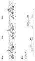
図11は、所定のサブフレームにおいて複数のスモールセルから送信されるDL信号の一例を示す図である。図11には、周波数スケジューリングを行う無線リソースの最小単位である1RB(リソースブロック)が示されている。図11では、参照信号(例えば、CRS)が、第0、4、7及び11番目のシンボルの第0、3、6及び9番目のサブキャリアに配置されている。また、同期信号(例えば、PSS)が、第6番目のシンボルに配置されている。また、非測定対象セルの検出/測定用信号(DS)が、第7及び8番目のシンボルの第11番目のサブキャリアに配置されている。また、測定対象セルの検出/測定用信号(DS)が、第9及び10番目のシンボルの第11番目のサブキャリアに配置されている。
FIG. 11 is a diagram illustrating an example of DL signals transmitted from a plurality of small cells in a predetermined subframe. FIG. 11
図11においては、ユーザ端末は、測定対象セルのDSを用いてRSRPを測定する。また、ユーザ端末は、測定対象セル及び非測定対象セルのいずれのDSをも含まないシンボル(第0−5、11−13番目のシンボル)でRSSIを測定することができる。なお、同期信号を含む第6番目のシンボルをRSSI測定に含めて、第0−6、11−13番目のシンボルでRSSIを測定してもよい。 In FIG. 11, a user terminal measures RSRP using DS of a measurement object cell. Further, the user terminal can measure RSSI with symbols (0-5th and 11-13th symbols) that do not include any DS of the measurement target cell and the non-measurement target cell. Note that the sixth symbol including the synchronization signal may be included in the RSSI measurement, and the RSSI may be measured using the 0-6th and 11-13th symbols.
なお、ユーザ端末は、検出/測定用信号が送信されるサブフレームのうち、測定対象セルに対応した検出/測定用信号でRSRPを測定する一方、検出/測定用信号が送信されるサブフレームの全OFDMシンボルでRSSIを求めてもよい。 Note that the user terminal measures RSRP with the detection / measurement signal corresponding to the measurement target cell among the subframes in which the detection / measurement signal is transmitted, while the user frame of the subframe in which the detection / measurement signal is transmitted The RSSI may be obtained for all OFDM symbols.
本発明の第3の態様に係る構成によれば、サブフレームの一部で検出/測定用信号が送信される場合において、1サブフレーム内でRSRP、RSSI、SINRなどの測定が可能となり、RSRQの値を適切に求めることができる。 According to the configuration of the third aspect of the present invention, when a detection / measurement signal is transmitted in a part of a subframe, it is possible to measure RSRP, RSSI, SINR, etc. within one subframe, and RSRQ Can be determined appropriately.
なお、第3の態様においても、上記変形例2のように、ネットワーク(例えば、マクロ基地局、スモール基地局など)は、上位レイヤ信号又は報知信号により、測定を切り替えるための情報(測定切り替え情報)をユーザ端末に通知してもよい。例えば、RSRQの算出式を切り替えるための情報を通知してもよい。また、ユーザ端末は、測定切り替え情報に基づいて、検出/測定用信号を用いた測定をサブフレーム単位で行うかシンボル単位で行うかを判断する構成としてもよい。
Also in the third mode, as in
また、上記理論式(1)、(2)、(4)の分母に含まれる各定数の整数値は、アンテナポート数に依存している。例えば、1RB(12サブキャリア)において1シンボルに割り当てられる参照信号(例えば、CRS)のサブキャリア数をaとした式を利用してもよい。このような場合、RSRQの算出式を、例えば、RSRQ=RSRPDS/(a・RSRPDS+(12−a)・RSSI)とすることができる。 In addition, the integer values of the constants included in the denominators of the theoretical formulas (1), (2), and (4) depend on the number of antenna ports. For example, an expression may be used in which the number of subcarriers of a reference signal (for example, CRS) allocated to one symbol in 1 RB (12 subcarriers) is a. In such a case, the RSRQ calculation formula can be, for example, RSRQ = RSRP DS / (a · RSRP DS + (12−a) · RSSI).
(無線通信システムの構成)
以下、本実施の形態に係る無線通信システムの構成について説明する。この無線通信システムでは、上記第1の態様、第2の態様、第3の態様に係る無線通信方法が適用される。なお、上記第1の態様、第2の態様、第3の態様に係る無線通信方法は、それぞれ単独で適用してもよいし、組み合わせて適用してもよい。
(Configuration of wireless communication system)
Hereinafter, the configuration of the wireless communication system according to the present embodiment will be described. In this wireless communication system, the wireless communication methods according to the first aspect, the second aspect, and the third aspect are applied. The wireless communication methods according to the first aspect, the second aspect, and the third aspect may be applied independently or in combination.
図6は、本実施の形態に係る無線通信システムの概略構成図である。図6に示すように、無線通信システム1は、マクロセルC1を形成するマクロ基地局11と、マクロセルC1内に配置され、マクロセルC1よりも狭いスモールセルC2を形成するスモール基地局12a及び12bとを備えている。ユーザ端末20は、マクロ基地局11、スモール基地局12a及び12b(以下、総称してスモール基地局12という)の少なくとも一つと無線通信可能に構成されている。なお、マクロ基地局11、スモール基地局12の数は、図6に示す数に限られない。
FIG. 6 is a schematic configuration diagram of the radio communication system according to the present embodiment. As shown in FIG. 6, the
マクロセルC1及びスモールセルC2では、同一の周波数帯が用いられてもよいし、異なる周波数帯が用いられてもよい。また、マクロ基地局11及び各スモール基地局12は、基地局間インタフェース(例えば、光ファイバ、X2インタフェース)を介して互いに接続される。マクロ基地局11及び各スモール基地局12は、それぞれ上位局装置30に接続され、上位局装置30を介してコアネットワーク40に接続される。なお、上位局装置30には、例えば、アクセスゲートウェイ装置、無線ネットワークコントローラ(RNC)、モビリティマネジメントエンティティ(MME)等が含まれるが、これに限定されるものではない。
In the macro cell C1 and the small cell C2, the same frequency band may be used, or different frequency bands may be used. The
なお、マクロ基地局11は、相対的に広いカバレッジを有する無線基地局であり、eNodeB(eNB)、無線基地局、送信ポイント(transmission point)などと呼ばれてもよい。スモール基地局12は、局所的なカバレッジを有する無線基地局であり、RRH(Remote Radio Head)、ピコ基地局、フェムト基地局、HeNB(Home eNodeB)、送信ポイント、eNodeB(eNB)などと呼ばれてもよい。ユーザ端末20は、LTE、LTE−Aなどの各種通信方式に対応した端末であり、移動通信端末だけでなく固定通信端末を含んでよい。
The
また、無線通信システム1では、無線アクセス方式として、下りリンクについてはOFDMA(直交周波数分割多元接続)が適用され、上りリンクについてはSC−FDMA(シングルキャリア−周波数分割多元接続)が適用される。
Further, in the
無線通信システム1では、下りリンクの通信チャネルとして、各ユーザ端末20で共有される下り共有チャネル(PDSCH:Physical Downlink Shared Channel)と、下り制御チャネル(PDCCH:Physical Downlink Control Channel、EPDCCH:Enhanced Physical Downlink Control Channel)、PCFICH、PHICH、報知チャネル(PBCH)などが用いられる。PDSCHにより、ユーザデータや上位レイヤ制御情報が伝送される。PDCCH、EPDCCHにより、下り制御情報(DCI)が伝送される。
In the
また、無線通信システム1では、上りリンクの通信チャネルとして、各ユーザ端末20で共有される上り共有チャネル(PUSCH:Physical Uplink Shared Channel)と、上り制御チャネル(PUCCH:Physical Uplink Control Channel)などが用いられる。PUSCHにより、ユーザデータや上位レイヤ制御情報が伝送される。また、PUCCHにより、下りリンクの無線品質情報(CQI:Channel Quality Indicator)や、送達確認情報(ACK/NACK)等が伝送される。
In the
以下、マクロ基地局11及びスモール基地局12を区別しない場合、無線基地局10と総称する。
Hereinafter, when the
図7は、本実施の形態に係る無線基地局10の全体構成図である。無線基地局10は、MIMO伝送のための複数の送受信アンテナ101と、アンプ部102と、送受信部103と、ベースバンド信号処理部104と、呼処理部105と、インタフェース部106とを備えている。
FIG. 7 is an overall configuration diagram of the radio base station 10 according to the present embodiment. The radio base station 10 includes a plurality of transmission /
下りリンクにより無線基地局10からユーザ端末20に送信されるユーザデータは、上位局装置30からインタフェース部106を介してベースバンド信号処理部104に入力される。
User data transmitted from the radio base station 10 to the
ベースバンド信号処理部104では、PDCPレイヤの処理、ユーザデータの分割・結合、RLC(Radio Link Control)再送制御の送信処理などのRLCレイヤの送信処理、MAC(Medium Access Control)再送制御、例えば、HARQの送信処理、スケジューリング、伝送フォーマット選択、チャネル符号化、逆高速フーリエ変換(IFFT:Inverse Fast Fourier Transform)処理、プリコーディング処理が行われて各送受信部103に転送される。また、下り制御信号に関しても、チャネル符号化や逆高速フーリエ変換等の送信処理が行われて、各送受信部103に転送される。
The baseband
各送受信部103は、ベースバンド信号処理部104からアンテナ毎にプリコーディングして出力された下り信号を無線周波数帯に変換する。アンプ部102は、周波数変換された無線周波数信号を増幅して送受信アンテナ101により送信する。
Each transmitting / receiving
一方、上り信号については、各送受信アンテナ101で受信された無線周波数信号がそれぞれアンプ部102で増幅され、各送受信部103で周波数変換されてベースバンド信号に変換され、ベースバンド信号処理部104に入力される。
On the other hand, for the uplink signal, the radio frequency signal received by each transmitting / receiving
ベースバンド信号処理部104では、入力された上り信号に含まれるユーザデータに対して、FFT処理、IDFT処理、誤り訂正復号、MAC再送制御の受信処理、RLCレイヤ、PDCPレイヤの受信処理がなされ、インタフェース部106を介して上位局装置30に転送される。呼処理部105は、通信チャネルの設定や解放等の呼処理や、無線基地局10の状態管理や、無線リソースの管理を行う。
The baseband
インタフェース部106は、基地局間インタフェース(例えば、光ファイバ、X2インタフェース)を介して隣接基地局と信号を送受信(バックホールシグナリング)する。例えば、マクロ基地局11とスモール基地局12間のデータの送受信をインタフェース部106を介して行う。あるいは、インタフェース部106は、所定のインタフェースを介して、上位局装置30と信号を送受信する。
The
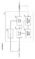
図8は、本実施の形態に係るマクロ基地局11の機能構成図である。なお、以下の機能構成は、マクロ基地局11が有するベースバンド信号処理部104などによって構成される。
FIG. 8 is a functional configuration diagram of the
図8に示すように、マクロ基地局11は、UE受信状態取得部301、受信品質算出部302、オン/オフ決定部303、スケジューラ304、DL信号生成部305を具備する。
As illustrated in FIG. 8, the
UE受信状態取得部301は、検出/測定用信号(Discovery信号)に対するユーザ端末20の受信状態に関する情報(MR)を取得する。なお、MRは、スモール基地局12から送信される検出/測定用信号(Discovery信号)を受信したユーザ端末20から報告される。例えば、UE受信状態取得部301は、ユーザ端末20で検出/測定された検出/測定用信号の受信電力(RSRP)、受信品質(RSRP)に関する情報をユーザ端末20から取得する(上記第1の態様)。
The UE reception
また、検出/測定用信号が送信されないサブフレームの総受信電力(RSSI)に関する情報をユーザ端末20がフィードバックする場合(上記第1の態様の変形例)、UE受信状態取得部301は、当該RSSIと検出/測定用信号の受信電力(RSRP)を取得する。また、ユーザ端末20が検出/測定用信号の受信SINRを報告する場合(上記第2の態様)、UE受信状態取得部301は、各ユーザ端末20からSINRを受信する。
When the
受信品質算出部302は、UE受信状態取得部301で取得した情報に基づいて、検出/測定用信号に対する各ユーザ端末20の受信品質を算出する。例えば、ユーザ端末20から、検出/測定用信号の受信電力(RSRP)と、検出/測定用信号が送信されないサブフレームの総受信電力(RSSI)に関する情報が報告される場合(上記第1の態様の変形例1)、受信品質算出部302は、当該RSRPとRSSIを用いて受信品質(RSRQ)を算出する。
The reception
具体的には、受信品質算出部302は、受信電力(RSRP)と、総受信電力(RSSI)に当該受信電力(RSRP)を加えた値と、の割合(比)に基づいて受信品質(RSRQ)を算出する。この際、受信品質算出部302で算出されるRSRQは、上記式(2)で表すことができる。また、受信品質算出部302は、ユーザ端末20から受信したRSRPとRSSIとを用いて新たなメトリックを生成してもよい。例えば、受信品質算出部302は、上記式(3)を利用することができる。受信品質算出部302で算出された結果は、オン/オフ決定部303に出力される。なお、ユーザ端末から受信品質(RSRQ)に関する情報が直接報告される場合には(上記第1の態様)、受信品質算出部302における処理を省略することができる。
Specifically, the reception
オン/オフ決定部303は、UE受信状態取得部301及び/又は受信品質算出部302から出力された情報に基づいて、スモール基地局のオン/オフを制御する。例えば、オン/オフ決定部303は、オフ状態(DTX状態)のスモール基地局をオン状態に移行することを決定し、インタフェース部106を介して当該スモール基地局に通知する。
The on / off
具体的に、オン/オフ決定部303は、検出/測定用信号の受信品質(RSRQ)が所定値以上となるユーザ端末20が複数存在する場合に、当該検出/測定用信号を送信したスモール基地局をオン状態に移行する。あるいは、オン/オフ決定部303は、検出/測定用信号に対するSINRを報告してきたユーザ端末に対し、所定値以上のSINRを有し、バッファ量が少ないスモール基地局を選択してオン状態に移行する。
Specifically, the on / off
スケジューラ304は、ユーザ端末20に送信するDL信号用の無線リソースの割当て(スケジューリング)を行う。例えば、スケジューラ304は、ユーザ端末に対して、DTX状態のスモール基地局から送信される検出/測定用信号に関するDS情報(検出/測定用信号の信号構成や送信タイミング(送信周期、送信期間)等)の生成をDL信号生成部305に指示する。
The
DL信号生成部305は、スケジューラ304からの指示に基づいてDL信号を生成する。例えば、DL信号生成部305は、制御信号、データ信号、参照信号等を生成する。また、DL信号生成部305は、DTX状態のスモール基地局から送信される検出/測定用信号に関する情報(DS情報)を上位レイヤ信号又は報知信号として生成する。DL信号生成部305で生成された信号は、送受信部103を介してユーザ端末20に送信される。
The DL
また、マクロ基地局11のUE受信状態取得部301は、セル固有参照信号(CRS)が送信されるサブフレームにおいて測定された受信電力及び総受信電力を用いて算出された受信品質(RSRQ)をユーザ端末から取得することができる。この場合、検出/測定用信号を用いて算出された受信品質と、セル固有参照信号を用いて算出された受信品質とを比較して、ユーザ端末が接続するセル(マクロセル又はスモールセル)を選択する選択部をマクロ基地局11にさらに設けてもよい。
In addition, the UE reception
図9は、本実施の形態に係るユーザ端末20の全体構成図である。ユーザ端末20は、MIMO伝送のための複数の送受信アンテナ201と、アンプ部202と、送受信部(受信部)203と、ベースバンド信号処理部204と、アプリケーション部205とを備えている。
FIG. 9 is an overall configuration diagram of the
下りリンクのデータについては、複数の送受信アンテナ201で受信された無線周波数信号がそれぞれアンプ部202で増幅され、送受信部203で周波数変換されてベースバンド信号に変換される。このベースバンド信号は、ベースバンド信号処理部204でFFT処理や、誤り訂正復号、再送制御の受信処理等がなされる。この下りリンクのデータの内、下りリンクのユーザデータは、アプリケーション部205に転送される。アプリケーション部205は、物理レイヤやMACレイヤより上位のレイヤに関する処理等を行う。また、下りリンクのデータの内、報知情報もアプリケーション部205に転送される。
For downlink data, radio frequency signals received by a plurality of transmission /
一方、上りリンクのユーザデータについては、アプリケーション部205からベースバンド信号処理部204に入力される。ベースバンド信号処理部204では、再送制御(H−ARQ (Hybrid ARQ))の送信処理や、チャネル符号化、プリコーディング、DFT処理、IFFT処理等が行われて各送受信部203に転送される。送受信部203は、ベースバンド信号処理部204から出力されたベースバンド信号を無線周波数帯に変換する。その後、アンプ部202は、周波数変換された無線周波数信号を増幅して送受信アンテナ201により送信する。
On the other hand, uplink user data is input from the
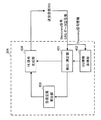
図10は、ユーザ端末20が有するベースバンド信号処理部204の主な機能構成図である。図10に示すように、ユーザ端末20が有するベースバンド信号処理部204は、検出/測定部401、DS情報取得部402、受信品質算出部403、UL信号生成部404を少なくとも有している。
FIG. 10 is a main functional configuration diagram of the baseband
検出/測定部401は、マクロ基地局11及び/又はスモール基地局12から送信されるDL信号の検出/測定を行う。例えば、検出/測定部401は、所定サブフレームにDTX状態のスモール基地局から送信される検出/測定用信号の受信電力(RSRP)と、検出/測定用信号が送信されないサブフレームにおけるDL信号の総受信電力(RSSI)とを測定する。なお、検出/測定部401は、DS情報取得部402から供給される情報を用いて検出/測定用信号を検出することにより、効率的に検出動作を行うことができる。
The detection /
また、検出/測定部401は、検出/測定用信号が送信されるサブフレームにおいて、当該検出/測定用信号の受信SINRを測定してもよい(上記第2の態様)。
Further, the detection /
DS情報取得部402は、DTX状態のスモール基地局から送信される検出/測定用信号に関するDS情報(検出/測定用信号の信号構成や送信タイミング(送信周期、送信期間)等)をマクロ基地局11から取得する。DS情報取得部402は、マクロ基地局11から受信したDS情報に基づいて、検出/測定用信号の送信タイミング等を特定して、検出/測定部401に出力する。
The DS
受信品質算出部403は、検出/測定部401で測定した検出/測定用信号の受信電力(RSRQ)と、検出/測定用信号が送信されないサブフレームの総受信電力(RSSI)を用いて受信品質(RSRQ)を算出する。具体的に、受信品質算出部403は、受信電力(RSRQ)と、総受信電力(RSSI)に受信電力(RSRQ)を加えた値と、の割合に基づいて受信品質(RSRQ)を算出する。この際、受信品質算出部403で算出されるRSRQは、上記式(2)で表されることとなる。
The reception
なお、ユーザ端末20からマクロ基地局11に対して、総受信電力(RSSI)そのものに関する情報を送信する場合(上記第1の態様の変形例1)や、検出/測定用信号に対するSINRに関する情報を送信する場合(上記第2の態様)、受信品質算出部403における処理を省略することができる。
In addition, when transmitting information related to the total received power (RSSI) itself from the
UL信号生成部404は、受信品質算出部403で算出された受信品質(RSRQ)や検出/測定部401で測定された受信電力(RSRP)に関する情報(メジャメントレポート)を上り信号として生成する。また、UL信号生成部404は、総受信電力(RSSI)そのものを送信する場合(上記第1の態様の変形例1)や、検出/測定用信号の受信SINRを送信する場合(上記第2の態様)、RSSI、SINRに関する情報を上り信号として生成する。また、UL信号生成部404は、送達確認信号等の上り制御信号や上りデータ信号の生成も行う。
The UL
以上、上述の実施形態を用いて本発明について詳細に説明したが、当業者にとっては、本発明が本明細書中に説明した実施形態に限定されるものではないということは明らかである。本発明は、特許請求の範囲の記載により定まる本発明の趣旨及び範囲を逸脱することなく修正及び変更態様として実施することができる。従って、本明細書の記載は、例示説明を目的とするものであり、本発明に対して何ら制限的な意味を有するものではない。また、各実施の態様は適宜組み合わせて適用することが可能である。 Although the present invention has been described in detail using the above-described embodiments, it is obvious to those skilled in the art that the present invention is not limited to the embodiments described in this specification. The present invention can be implemented as modified and changed modes without departing from the spirit and scope of the present invention defined by the description of the scope of claims. Therefore, the description of the present specification is for illustrative purposes and does not have any limiting meaning to the present invention. Moreover, each embodiment can be applied in combination as appropriate.
1…無線通信システム
10…無線基地局
11…マクロ基地局
12、12a、12b…スモール基地局
20…ユーザ端末
30…上位局装置
40…コアネットワーク
101…送受信アンテナ
102…アンプ部
103…送受信部
104…ベースバンド信号処理部
105…呼処理部
106…インタフェース部
201…送受信アンテナ
202…アンプ部
203…送受信部
204…ベースバンド信号処理部
205…アプリケーション部
301…UE受信状態取得部
302…受信品質算出部
303…オン/オフ決定部
304…スケジューラ
305…DL信号生成部
401…検出/測定部
402…DS情報取得部
403…受信品質算出部
404…UL信号生成部
DESCRIPTION OF
Claims (3)
前記ディスカバリ信号に関する情報に基づいて、前記ディスカバリ信号の受信電力(RSRP)と、前記ディスカバリ信号が送信されるサブフレームにおける下り信号の総受信電力(RSSI)と、を測定する測定部と、
測定結果に関する情報を前記ネットワークに送信する送信部と、を有し、
前記ディスカバリ信号が前記サブフレームの一部のシンボルを用いて送信される場合、前記測定部は、前記ディスカバリ信号が送信されるサブフレームにおける下り信号の全OFDMシンボルでRSSIを測定することを特徴とするユーザ端末。 A receiving unit that receives a discovery (Discovery) signal transmitted from a first cell whose on / off of the cell is controlled by the network, and information related to a discovery signal transmitted from the second cell ;
A measurement unit that measures received power (RSRP) of the discovery signal and total received power (RSSI) of a downlink signal in a subframe in which the discovery signal is transmitted , based on information on the discovery signal;
A transmission unit for transmitting information on measurement results to the network ,
When the discovery signal is transmitted using a part of symbols of the subframe, the measurement unit measures RSSI with all OFDM symbols of downlink signals in the subframe in which the discovery signal is transmitted. User terminal.
前記ユーザ端末がディスカバリ信号に関する情報に基づいて測定した前記ディスカバリ信号の受信電力(RSRP)と、前記ディスカバリ信号が送信されるサブフレームにおける下り信号の全OFDMシンボルで測定された総受信電力(RSSI)との測定結果に関する情報を受信する受信部と、
前記受信部で受信した情報に基づいて前記所定セルのオン/オフを決定する決定部と、を有することを特徴とする基地局。 A transmission unit that transmits a discovery signal to a user terminal using a partial symbol of a subframe in a predetermined cell;
The received power (RSRP) of the discovery signal measured by the user terminal based on information on the discovery signal, and the total received power (RSSI) measured in all OFDM symbols of the downlink signal in the subframe in which the discovery signal is transmitted A receiver for receiving information on the measurement results of
A base station comprising: a determination unit that determines on / off of the predetermined cell based on information received by the reception unit .
ネットワークによりセルのオン/オフが制御される第1のセルから送信されるディスカバリ(Discovery)信号と、第2のセルから送信されるディスカバリ信号に関する情報とを受信する工程と、
前記ディスカバリ信号に関する情報に基づいて、前記ディスカバリ信号の受信電力(RSRP)と、前記ディスカバリ信号が送信されるサブフレームにおける下り信号の総受信電力(RSSI)と、を測定する工程と、
測定結果に関する情報を前記ネットワークに送信する工程と、を有し、
前記ディスカバリ信号が前記サブフレームの一部のシンボルを用いて送信される場合、前記ディスカバリ信号が送信されるサブフレームにおける下り信号の全OFDMシンボルでRSSIを測定することを特徴とする無線通信方法。 A wireless communication method for a user terminal,
Receiving a discovery signal transmitted from a first cell whose ON / OFF is controlled by the network, and information relating to a discovery signal transmitted from the second cell ;
Measuring received power (RSRP) of the discovery signal and total received power (RSSI) of a downlink signal in a subframe in which the discovery signal is transmitted based on information on the discovery signal;
Transmitting information relating to measurement results to the network ,
When the discovery signal is transmitted using a part of symbols of the subframe, the RSSI is measured with all OFDM symbols of downlink signals in the subframe in which the discovery signal is transmitted.
Priority Applications (5)
| Application Number | Priority Date | Filing Date | Title |
|---|---|---|---|
| JP2014058178A JP6096142B2 (en) | 2013-08-08 | 2014-03-20 | User terminal, base station, and wireless communication method |
| PCT/JP2014/069146 WO2015019825A1 (en) | 2013-08-08 | 2014-07-18 | User terminal, base station, and wireless communication method |
| US14/910,318 US10154479B2 (en) | 2013-08-08 | 2014-07-18 | User terminal, base station and radio communication method |
| EP14833978.1A EP3032890A4 (en) | 2013-08-08 | 2014-07-18 | User terminal, base station, and wireless communication method |
| CN201480045375.8A CN105453663A (en) | 2013-08-08 | 2014-07-18 | User terminal, base station, and wireless communication method |
Applications Claiming Priority (3)
| Application Number | Priority Date | Filing Date | Title |
|---|---|---|---|
| JP2013165507 | 2013-08-08 | ||
| JP2013165507 | 2013-08-08 | ||
| JP2014058178A JP6096142B2 (en) | 2013-08-08 | 2014-03-20 | User terminal, base station, and wireless communication method |
Publications (3)
| Publication Number | Publication Date |
|---|---|
| JP2015053667A JP2015053667A (en) | 2015-03-19 |
| JP2015053667A5 JP2015053667A5 (en) | 2016-08-25 |
| JP6096142B2 true JP6096142B2 (en) | 2017-03-15 |
Family
ID=52461164
Family Applications (1)
| Application Number | Title | Priority Date | Filing Date |
|---|---|---|---|
| JP2014058178A Active JP6096142B2 (en) | 2013-08-08 | 2014-03-20 | User terminal, base station, and wireless communication method |
Country Status (5)
| Country | Link |
|---|---|
| US (1) | US10154479B2 (en) |
| EP (1) | EP3032890A4 (en) |
| JP (1) | JP6096142B2 (en) |
| CN (1) | CN105453663A (en) |
| WO (1) | WO2015019825A1 (en) |
Families Citing this family (13)
| Publication number | Priority date | Publication date | Assignee | Title |
|---|---|---|---|---|
| JP2016536838A (en) * | 2013-09-30 | 2016-11-24 | 富士通株式会社 | Signal measuring method, user apparatus, and base station |
| WO2015097998A1 (en) | 2013-12-25 | 2015-07-02 | パナソニック インテレクチュアル プロパティ コーポレーション オブ アメリカ | Mobile station and reception quality measurement method |
| CN105101282A (en) * | 2014-05-21 | 2015-11-25 | 中兴通讯股份有限公司 | Discovery signal measurement method, discovery signal measurement device and user terminal |
| TWI692259B (en) * | 2014-07-16 | 2020-04-21 | 日商新力股份有限公司 | Telecommunications apparatus and methods |
| KR101582598B1 (en) * | 2014-07-31 | 2016-01-05 | 에스케이텔레콤 주식회사 | Terminal device and control method thereof |
| EP3177058B1 (en) * | 2014-07-31 | 2019-09-25 | Nanchang Coolpad Intelligent Technology Company Limited | Method and system for maintaining time-frequency synchronisation, and terminal |
| JP6636038B2 (en) * | 2015-04-02 | 2020-01-29 | テレフオンアクチーボラゲット エルエム エリクソン(パブル) | User equipment and method for link quality determination |
| WO2017014111A1 (en) * | 2015-07-22 | 2017-01-26 | シャープ株式会社 | Terminal device, base station device, measurement method, and integrated circuit |
| EP4102880A1 (en) * | 2015-07-29 | 2022-12-14 | Apple Inc. | User equipment (ue) and methods for dynamic millimeter wave pencil cell communication |
| JP2017063326A (en) * | 2015-09-24 | 2017-03-30 | 株式会社Nttドコモ | User terminal, radio base station, and radio communication method |
| US10320539B2 (en) * | 2016-05-23 | 2019-06-11 | Nokia Technologies Oy | Methods and apparatuses for reference signal adaptation based on incoming user mobility information |
| EP3477880B1 (en) * | 2017-06-29 | 2022-03-23 | LG Electronics Inc. | Measurement execution method and user equipment, and measurement configuration method and base station |
| CN115333655B (en) * | 2022-10-10 | 2024-03-26 | 华安中云股份有限公司 | Method and device for automatically detecting interference, knapsack base station and storage medium |
Family Cites Families (18)
| Publication number | Priority date | Publication date | Assignee | Title |
|---|---|---|---|---|
| JP4684124B2 (en) * | 2006-02-16 | 2011-05-18 | 富士通株式会社 | Mobile station apparatus and transmission power control method in the same |
| CN102014422A (en) * | 2009-09-08 | 2011-04-13 | 中兴通讯股份有限公司 | Measurement processing method and device |
| KR101676033B1 (en) * | 2010-01-08 | 2016-11-29 | 삼성전자주식회사 | Method and apparatus for power consumption reduction of base station in wireless communication system |
| CA2784035C (en) * | 2010-03-29 | 2020-07-21 | Lg Electronics Inc. | Method and apparatus for measurement for inter-cell interference coordination in radio communication system |
| US9125072B2 (en) * | 2010-04-13 | 2015-09-01 | Qualcomm Incorporated | Heterogeneous network (HetNet) user equipment (UE) radio resource management (RRM) measurements |
| US9609536B2 (en) * | 2010-04-13 | 2017-03-28 | Qualcomm Incorporated | Measurement of received power and received quality in a wireless communication network |
| US9031530B2 (en) * | 2010-11-08 | 2015-05-12 | Qualcomm Incorporated | System and method for assisting in powering on sleeping network entities |
| US9008675B2 (en) * | 2010-11-22 | 2015-04-14 | Lg Electronics Inc. | Method and device for measuring a downlink in a wireless communication system |
| KR20120099568A (en) * | 2011-01-18 | 2012-09-11 | 삼성전자주식회사 | Method and appratus for measuring inteference from in-device communication module in wireless communication system |
| JP2014150300A (en) * | 2011-05-31 | 2014-08-21 | Panasonic Corp | Radio communication terminal, radio communication device, and cell measuring method |
| KR101896001B1 (en) * | 2011-07-12 | 2018-09-06 | 한국전자통신연구원 | Method of mobility management for mobile terminal in a heterogeneous network environment |
| US9794811B2 (en) * | 2011-07-29 | 2017-10-17 | Lg Electronics Inc. | Cell measuring method and information transmitting method therefor |
| EP4142173A1 (en) * | 2011-08-05 | 2023-03-01 | Panasonic Intellectual Property Corporation of America | Csi-rs reporting for base stations having multiple transmission points |
| US8848560B2 (en) * | 2011-11-04 | 2014-09-30 | Blackberry Limited | Apparatus and method for adaptive transmission during almost blank subframes in a wireless communication network |
| KR101618132B1 (en) * | 2012-04-06 | 2016-05-04 | 엘지전자 주식회사 | An apparatus for receiving downlink signal in a wireless communication system and method thereof |
| WO2013154382A1 (en) * | 2012-04-12 | 2013-10-17 | 엘지전자 주식회사 | Method and device for measuring interference in wireless communication system |
| CN102752767B (en) * | 2012-07-02 | 2014-12-10 | 厦门大学 | Method for improving performance of cell edge users by using multi-objective genetic algorithm |
| US9526044B2 (en) * | 2013-05-08 | 2016-12-20 | Lg Electronics Inc. | Method of configuring dual connectivity to UE in heterogeneous cell deployment |
-
2014
- 2014-03-20 JP JP2014058178A patent/JP6096142B2/en active Active
- 2014-07-18 WO PCT/JP2014/069146 patent/WO2015019825A1/en active Application Filing
- 2014-07-18 CN CN201480045375.8A patent/CN105453663A/en active Pending
- 2014-07-18 US US14/910,318 patent/US10154479B2/en active Active
- 2014-07-18 EP EP14833978.1A patent/EP3032890A4/en not_active Withdrawn
Also Published As
| Publication number | Publication date |
|---|---|
| US20160192334A1 (en) | 2016-06-30 |
| JP2015053667A (en) | 2015-03-19 |
| WO2015019825A1 (en) | 2015-02-12 |
| EP3032890A4 (en) | 2017-07-05 |
| US10154479B2 (en) | 2018-12-11 |
| CN105453663A (en) | 2016-03-30 |
| EP3032890A1 (en) | 2016-06-15 |
Similar Documents
| Publication | Publication Date | Title |
|---|---|---|
| JP6096142B2 (en) | User terminal, base station, and wireless communication method | |
| CN106664649B (en) | Radio base station, user terminal, and radio communication system | |
| JP6359815B2 (en) | User terminal, radio base station, and different frequency measurement method | |
| JP6204693B2 (en) | Wireless base station and wireless communication method | |
| JP6174265B2 (en) | User terminal and wireless communication method | |
| JP6399778B2 (en) | User terminal, base station, communication system and communication method | |
| JP6219110B2 (en) | Radio base station, user terminal, and communication control method | |
| WO2016072221A1 (en) | User terminal, wireless base station, and wireless communication method | |
| WO2018198342A1 (en) | User terminal and wireless communication method | |
| JP6301065B2 (en) | Radio base station, user terminal, and radio communication method | |
| WO2018084135A1 (en) | Device and radio communication method | |
| WO2014148181A1 (en) | User terminal, radio base station, and radio communication method | |
| JP2014204200A (en) | Radio base station, user terminal, and radio communication method | |
| JP6290554B2 (en) | Radio base station and radio communication method | |
| CN105580411B (en) | Base station, user terminal, and wireless communication method | |
| CN111201760B (en) | User terminal and wireless communication method | |
| JP2015033015A (en) | Base station, user terminal, and radio communication control method | |
| JP6955611B2 (en) | Terminals, wireless communication methods and wireless base stations | |
| CN111683392B (en) | Base station, user terminal, and wireless communication method |
Legal Events
| Date | Code | Title | Description |
|---|---|---|---|
| A521 | Request for written amendment filed |
Free format text: JAPANESE INTERMEDIATE CODE: A523 Effective date: 20160708 |
|
| A621 | Written request for application examination |
Free format text: JAPANESE INTERMEDIATE CODE: A621 Effective date: 20160708 |
|
| A871 | Explanation of circumstances concerning accelerated examination |
Free format text: JAPANESE INTERMEDIATE CODE: A871 Effective date: 20160708 |
|
| A975 | Report on accelerated examination |
Free format text: JAPANESE INTERMEDIATE CODE: A971005 Effective date: 20160727 |
|
| A131 | Notification of reasons for refusal |
Free format text: JAPANESE INTERMEDIATE CODE: A131 Effective date: 20160913 |
|
| A521 | Request for written amendment filed |
Free format text: JAPANESE INTERMEDIATE CODE: A523 Effective date: 20161114 |
|
| TRDD | Decision of grant or rejection written | ||
| A01 | Written decision to grant a patent or to grant a registration (utility model) |
Free format text: JAPANESE INTERMEDIATE CODE: A01 Effective date: 20170117 |
|
| A61 | First payment of annual fees (during grant procedure) |
Free format text: JAPANESE INTERMEDIATE CODE: A61 Effective date: 20170215 |
|
| R150 | Certificate of patent or registration of utility model |
Ref document number: 6096142 Country of ref document: JP Free format text: JAPANESE INTERMEDIATE CODE: R150 |
|
| R250 | Receipt of annual fees |
Free format text: JAPANESE INTERMEDIATE CODE: R250 |
|
| R250 | Receipt of annual fees |
Free format text: JAPANESE INTERMEDIATE CODE: R250 |
|
| R250 | Receipt of annual fees |
Free format text: JAPANESE INTERMEDIATE CODE: R250 |
|
| R250 | Receipt of annual fees |
Free format text: JAPANESE INTERMEDIATE CODE: R250 |
|
| R250 | Receipt of annual fees |
Free format text: JAPANESE INTERMEDIATE CODE: R250 |