JP6094331B2 - Goods transport equipment - Google Patents
Goods transport equipment Download PDFInfo
- Publication number
- JP6094331B2 JP6094331B2 JP2013074846A JP2013074846A JP6094331B2 JP 6094331 B2 JP6094331 B2 JP 6094331B2 JP 2013074846 A JP2013074846 A JP 2013074846A JP 2013074846 A JP2013074846 A JP 2013074846A JP 6094331 B2 JP6094331 B2 JP 6094331B2
- Authority
- JP
- Japan
- Prior art keywords
- carriage
- wheel
- cart
- along
- transport
- Prior art date
- Legal status (The legal status is an assumption and is not a legal conclusion. Google has not performed a legal analysis and makes no representation as to the accuracy of the status listed.)
- Active
Links
- 230000001105 regulatory effect Effects 0.000 claims description 14
- 230000008878 coupling Effects 0.000 description 5
- 238000010168 coupling process Methods 0.000 description 5
- 238000005859 coupling reaction Methods 0.000 description 5
- 230000010355 oscillation Effects 0.000 description 3
- 238000009434 installation Methods 0.000 description 2
- 238000006073 displacement reaction Methods 0.000 description 1
- 230000001360 synchronised effect Effects 0.000 description 1
Images


Classifications
-
- B—PERFORMING OPERATIONS; TRANSPORTING
- B65—CONVEYING; PACKING; STORING; HANDLING THIN OR FILAMENTARY MATERIAL
- B65G—TRANSPORT OR STORAGE DEVICES, e.g. CONVEYORS FOR LOADING OR TIPPING, SHOP CONVEYOR SYSTEMS OR PNEUMATIC TUBE CONVEYORS
- B65G47/00—Article or material-handling devices associated with conveyors; Methods employing such devices
- B65G47/74—Feeding, transfer, or discharging devices of particular kinds or types
- B65G47/94—Devices for flexing or tilting travelling structures; Throw-off carriages
- B65G47/96—Devices for tilting links or platform
- B65G47/962—Devices for tilting links or platform tilting about an axis substantially parallel to the conveying direction
-
- B—PERFORMING OPERATIONS; TRANSPORTING
- B65—CONVEYING; PACKING; STORING; HANDLING THIN OR FILAMENTARY MATERIAL
- B65G—TRANSPORT OR STORAGE DEVICES, e.g. CONVEYORS FOR LOADING OR TIPPING, SHOP CONVEYOR SYSTEMS OR PNEUMATIC TUBE CONVEYORS
- B65G17/00—Conveyors having an endless traction element, e.g. a chain, transmitting movement to a continuous or substantially-continuous load-carrying surface or to a series of individual load-carriers; Endless-chain conveyors in which the chains form the load-carrying surface
- B65G17/06—Conveyors having an endless traction element, e.g. a chain, transmitting movement to a continuous or substantially-continuous load-carrying surface or to a series of individual load-carriers; Endless-chain conveyors in which the chains form the load-carrying surface having a load-carrying surface formed by a series of interconnected, e.g. longitudinal, links, plates, or platforms
- B65G17/065—Conveyors having an endless traction element, e.g. a chain, transmitting movement to a continuous or substantially-continuous load-carrying surface or to a series of individual load-carriers; Endless-chain conveyors in which the chains form the load-carrying surface having a load-carrying surface formed by a series of interconnected, e.g. longitudinal, links, plates, or platforms the load carrying surface being formed by plates or platforms attached to a single traction element
- B65G17/066—Conveyors having an endless traction element, e.g. a chain, transmitting movement to a continuous or substantially-continuous load-carrying surface or to a series of individual load-carriers; Endless-chain conveyors in which the chains form the load-carrying surface having a load-carrying surface formed by a series of interconnected, e.g. longitudinal, links, plates, or platforms the load carrying surface being formed by plates or platforms attached to a single traction element specially adapted to follow a curved path
-
- B—PERFORMING OPERATIONS; TRANSPORTING
- B65—CONVEYING; PACKING; STORING; HANDLING THIN OR FILAMENTARY MATERIAL
- B65G—TRANSPORT OR STORAGE DEVICES, e.g. CONVEYORS FOR LOADING OR TIPPING, SHOP CONVEYOR SYSTEMS OR PNEUMATIC TUBE CONVEYORS
- B65G21/00—Supporting or protective framework or housings for endless load-carriers or traction elements of belt or chain conveyors
- B65G21/20—Means incorporated in, or attached to, framework or housings for guiding load-carriers, traction elements or loads supported on moving surfaces
- B65G21/22—Rails or the like engaging sliding elements or rollers attached to load-carriers or traction elements
-
- B—PERFORMING OPERATIONS; TRANSPORTING
- B65—CONVEYING; PACKING; STORING; HANDLING THIN OR FILAMENTARY MATERIAL
- B65G—TRANSPORT OR STORAGE DEVICES, e.g. CONVEYORS FOR LOADING OR TIPPING, SHOP CONVEYOR SYSTEMS OR PNEUMATIC TUBE CONVEYORS
- B65G54/00—Non-mechanical conveyors not otherwise provided for
- B65G54/02—Non-mechanical conveyors not otherwise provided for electrostatic, electric, or magnetic
Landscapes
- Engineering & Computer Science (AREA)
- Mechanical Engineering (AREA)
- Handcart (AREA)
- Warehouses Or Storage Devices (AREA)
- Discharge Of Articles From Conveyors (AREA)
- Non-Mechanical Conveyors (AREA)
Description
本発明は、走行経路に沿って移動自在な物品搬送用の搬送台車を前記走行経路に沿って複数台連結させた台車列と、前記台車列を前記走行経路に沿って移動させる駆動装置と、が設けられ、前記複数台の搬送台車の夫々が、台車本体と、前記走行経路に沿って形成された走行面上を転動する車輪と、前記台車本体の前端部に備えられた第1連結部と、前記台車本体の後端部に備えられた第2連結部と、を備え、前記第1連結部が、前方に隣接する別の搬送台車の前記第2連結部と上下方向に沿う台車揺動軸心周りに揺動自在に連結される物品搬送設備に関する。 The present invention includes a carriage train in which a plurality of transport carts for conveying articles that are movable along a travel route are connected along the travel route, a drive device that moves the carriage train along the travel route, and Each of the plurality of transport carts is provided with a cart body, wheels that roll on a travel surface formed along the travel route, and a first connection provided at a front end of the cart body And a second connecting portion provided at a rear end portion of the cart main body, and the first connecting portion is a cart along the vertical direction with the second connecting portion of another transport cart adjacent to the front. The present invention relates to an article transport facility that is swingably connected around a swing axis.
かかる物品搬送設備は、搬送台車の第1連結部を、走行方向の前方側に隣接する別の搬送台車の第2連結部に連結するようにして、複数台の搬送台車にて台車列を形成し、その台車列を駆動装置にて走行経路に沿って移動させて物品を搬送するものである。そして、このような物品搬送設備の従来例として、走行面上を転動する車輪を、台車本体の後端部に設けているものや(例えば、特許文献1参照。)、搬送台車の前端部に設けているものがある(例えば、特許文献2参照。)。 Such an article conveyance facility forms a carriage train with a plurality of carriages so that the first linkage of the carriage is connected to the second linkage of another carriage adjacent to the front side in the traveling direction. Then, the carriage train is moved along the travel path by the driving device to convey the article. And as a prior art example of such an article conveyance facility, a wheel that rolls on the traveling surface is provided at the rear end of the carriage main body (see, for example, Patent Document 1), or the front end of the conveyance carriage. (For example, refer to Patent Document 2).
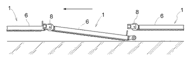
特許文献1の物品搬送設備のように、車輪を台車本体の後端部に設けた場合では、台車本体の前端部は、前側に隣接する搬送台車の第2連結部との連結により支持されているだけである。そのため、図12に示すように、搬送台車1aとその前側に隣接する搬送台車1bとの連結が外れると、後側の搬送台車1aの前端部が落下してしまい、後側の搬送台車1aの姿勢は前傾姿勢となる。後側の搬送台車1aが走行中にこのような前傾姿勢になると、後側の搬送台車1aの前端部が、走行経路が設置される床面上に存在する凹凸や構造物に突っ張る状態で接触して、後側の搬送台車1a及びそれに後続する別の搬送台車が破損する恐れがある。
In the case where the wheel is provided at the rear end portion of the carriage main body as in the article conveyance facility of
また、特許文献2の物品搬送設備では、車輪を、台車本体の前端部に設けることで、台車本体の前端部は、前側に隣接する搬送台車の第2連結部との連結に加えて車輪により支持されているため、上述のような不具合は発生しない。ちなみに、台車本体の後端部は、後側に隣接する搬送台車の第1連結部との連結により支持されているだけであるが、連結が外れても台車本体の姿勢は後傾姿勢となるため、仮に床面上に凹凸や構造物が存在していても、台車本体の前端部が通過した後、台車本体の後端部が凹凸等に乗り上げることで、台車本体が凹凸等に接触するにしても台車本体が突っ張る状態で接触することを回避できる。
しかしながら、特許文献2の物品搬送設備では、車輪が第1連結部より後方に位置している。そのため、図13に示すように、走行経路に水平部分r1と傾斜部分r2とがある場合において、例えば、搬送台車が傾斜部分r2と水平部分r1との接続部を通過するときに、搬送台車1aの第1連結部10aは、水平部分r1を走行するときの位置(図13にて仮想線で示す位置)よりも一旦低くなる(図13にて実線で示す位置)ため、搬送台車が安定よく走行できないという不具合がある。
Moreover, in the article conveyance equipment of
However, in the article transport facility of
本発明は、上記実状に鑑みて為されたものであって、その目的は、隣接する別の搬送台車との連結が外れた場合の搬送台車の破損を回避しながら搬送台車を安定よく走行させることができる物品搬送設備を提供する点にある。 The present invention has been made in view of the above circumstances, and its purpose is to make the transport carriage run stably while avoiding damage to the transport carriage when it is disconnected from another adjacent transport carriage. It is in the point which provides the goods conveyance equipment which can be.
本発明にかかる物品搬送設備の第1特徴構成は、走行経路に沿って移動自在な物品搬送用の搬送台車を前記走行経路に沿って複数台連結させた台車列と、前記台車列を前記走行経路に沿って移動させる駆動装置と、が設けられ、前記複数台の搬送台車の夫々が、台車本体と、前記走行経路に沿って形成された走行面上を転動する車輪と、前記台車本体の前端部に備えられた第1連結部と、前記台車本体の後端部に備えられた第2連結部と、を備え、前記第1連結部が、前方に隣接する別の搬送台車の前記第2連結部と上下方向に沿う台車揺動軸心周りに揺動自在に連結されるものであって、
前記車輪が、前記台車本体の前端部に設けられ、前記車輪と前記第1連結部の前記台車揺動軸心とが、台車横幅方向視で重複し、前記複数台の搬送台車の夫々が、前記搬送台車が水平姿勢である状態において上下方向に沿う車輪揺動軸心周りに回転自在に前記台車本体に連結されたキャスター枠を備え、前記キャスター枠が、前記車輪の回転軸心である車輪回転軸心が前記車輪揺動軸心に対して水平方向に異なる位置となる状態で前記車輪を回転自在に支持し、前記キャスター枠が、前記車輪揺動軸心より後方に前記車輪回転軸心が位置し且つ前記車輪回転軸心が台車横幅方向に沿う姿勢となる直進走行状態において、前記車輪と前記台車揺動軸心とが、台車横幅方向視で重複し、前記複数の搬送台車の夫々が、前記走行経路に沿って設けられた案内レールに接触して前記台車本体の台車横幅方向への移動を規制する規制体を備え、前記規制体は、上下方向に沿う規制体回転軸心周りに回転自在で設けられ、且つ、前記直進走行状態において、前記規制体回転軸心が台車前後方向で前記車輪回転軸心と前記車輪揺動軸心との間に位置する点にある。
A first characteristic configuration of an article conveying facility according to the present invention includes a carriage row in which a plurality of carriages for article conveyance that are movable along a running route are connected along the running route, and the carriage row that runs through the carriage row. A drive device that moves along a route, and each of the plurality of transport carts rolls on a running surface formed on the running surface formed along the running route, and the dolly body A first connecting portion provided at a front end of the carriage body, and a second connecting portion provided at a rear end portion of the carriage main body, wherein the first connecting portion is adjacent to the front of another transport carriage. The second coupling part is pivotably coupled around the bogie pivot axis along the vertical direction,
The wheel is provided at a front end portion of the cart body, and the wheel and the cart swing axis of the first connecting portion overlap each other when viewed in a cart transverse direction, and each of the plurality of transport carts is A wheel having a caster frame coupled to the carriage main body so as to be rotatable around a wheel swing axis along a vertical direction in a state where the transport carriage is in a horizontal posture, and the caster frame is a wheel whose rotation axis is the wheel The wheel is rotatably supported in a state where the rotation axis is in a different position in the horizontal direction with respect to the wheel swing axis, and the caster frame is behind the wheel swing axis and the wheel rotation axis. And the wheel rotation axis is in a straight traveling state in which the wheel rotation axis is in a posture along the cart lateral width direction, the wheel and the cart swinging shaft center overlap each other when viewed from the cart lateral width direction, and each of the plurality of transport carts Is provided along the travel route A regulation body that contacts the guide rail and regulates movement of the carriage body in the lateral width direction of the carriage, and the regulation body is provided rotatably around a regulation body rotation axis along the vertical direction, and In the straight traveling state, the restricting body rotation axis is located between the wheel rotation axis and the wheel swing axis in the longitudinal direction of the carriage .
すなわち、車輪を台車本体の前端部に設けているため、前側に隣接する搬送台車との連結が外れた場合でも、台車本体の前端部が車輪によって支持されていることで、台車本体の前端部が落下することを回避できる。
また、第1連結部の台車揺動軸心は、台車横幅方向視で車輪と重複しており、例えば、走行経路に水平部分と傾斜部分とがある場合において、台車本体が水平部分と傾斜部分との接続部を通過するときに、車輪が接続部を通過するタイミングと第1連結部の台車揺動軸心が接続部を通過するタイミングとを近づけることができるため、第1連結部が走行面に対して上下動し難くなり、搬送台車を安定よく走行させることができる。
そして、直進走行する搬送台車の走行方向が直進方向とは異なる方向に変わった場合は、キャスター枠が車輪回転軸心周りに回転して車輪の向きが搬送台車の走行方向に対応した向きに変更されるため、搬送台車を安定よく所望の方向に走行させることができる。
そして、キャスター枠に支持された車輪は、直進走行状態では車輪揺動軸心より後方に車輪回転軸心が位置するが、このような車輪と台車揺動軸心とを、台車横幅方向視で重複させることで、第1連結部が走行面に対して上下動し難くなり、搬送台車を安定よく走行させることができる。
That is, since the wheel is provided at the front end of the truck body, the front end of the truck body is supported by the wheel even when the connection with the transport carriage adjacent to the front side is disconnected. Can be prevented from falling.
Further, the bogie swing axis of the first connecting portion overlaps with the wheel when viewed from the lateral direction of the bogie. For example, when the travel path includes a horizontal portion and an inclined portion, the bogie main body has a horizontal portion and an inclined portion. When the vehicle passes through the connecting portion, the timing at which the wheel passes through the connecting portion and the timing at which the cart swing axis of the first connecting portion passes through the connecting portion can be made closer, so the first connecting portion travels. It becomes difficult to move up and down with respect to the surface, and the transport carriage can be driven stably.
If the travel direction of the transport cart that travels straight changes to a direction different from the straight travel direction, the caster frame rotates around the wheel rotation axis and the direction of the wheels changes to the direction corresponding to the travel direction of the transport cart. Therefore, the transport carriage can be stably driven in a desired direction.
The wheels supported by the caster frame have a wheel rotation axis positioned behind the wheel swing axis in a straight traveling state. These wheels and the truck swing axis can be seen in the horizontal direction of the truck. By making it overlap, it becomes difficult for the 1st connection part to move up and down with respect to a running surface, and it can run a conveyance trolley stably.
本発明にかかる物品搬送設備の第2特徴構成は、走行経路に沿って移動自在な物品搬送用の搬送台車を前記走行経路に沿って複数台連結させた台車列と、前記台車列を前記走行経路に沿って移動させる駆動装置と、が設けられ、前記複数台の搬送台車の夫々が、台車本体と、前記走行経路に沿って形成された走行面上を転動する車輪と、前記台車本体の前端部に備えられた第1連結部と、前記台車本体の後端部に備えられた第2連結部と、を備え、前記第1連結部が、前方に隣接する別の搬送台車の前記第2連結部と上下方向に沿う台車揺動軸心周りに揺動自在に連結されるものであって、
前記車輪が、前記台車本体の前端部に設けられ、前記車輪と前記第1連結部の前記台車揺動軸心とが、台車横幅方向視で重複し、前記複数台の搬送台車の夫々が、前記搬送台車が水平姿勢である状態において上下方向に沿う車輪揺動軸心周りに回転自在に前記台車本体に連結されたキャスター枠を備え、前記キャスター枠が、前記車輪の回転軸心である車輪回転軸心が前記車輪揺動軸心に対して水平方向に異なる位置となる状態で前記車輪を回転自在に支持し、前記キャスター枠が、前記車輪揺動軸心より後方に前記車輪回転軸心が位置し且つ前記車輪回転軸心が台車横幅方向に沿う姿勢となる直進走行状態において、前記車輪と前記台車揺動軸心とが、台車横幅方向視で重複し、前記走行経路に沿って設けられて上面にて前記走行面を形成する走行レールが設けられ、前記複数の搬送台車の夫々が、前記走行経路に沿って設けられた案内レールに接触して前記台車本体の台車横幅方向への移動を規制する規制体を備え、前記規制体が、前記直進走行状態において台車横幅方向視で前記車輪揺動軸心と重複する揺動重複箇所に設けられ、前記規制体が、前記揺動重複箇所と、前記直進走行状態において上下方向視で前記車輪回転軸心と重複する回転重複箇所と、に台車前後方向での位置を変更自在に設けられている点にある。
A second characteristic configuration of the article transport facility according to the present invention includes: a carriage train in which a plurality of article carriages for article conveyance that are movable along a travel path are connected along the travel path; A drive device that moves along a route, and each of the plurality of transport carts rolls on a running surface formed on the running surface formed along the running route, and the dolly body A first connecting portion provided at a front end of the carriage body, and a second connecting portion provided at a rear end portion of the carriage main body, wherein the first connecting portion is adjacent to the front of another transport carriage. The second coupling part is pivotably coupled around the bogie pivot axis along the vertical direction,
The wheel is provided at a front end portion of the cart body, and the wheel and the cart swing axis of the first connecting portion overlap each other when viewed in a cart transverse direction, and each of the plurality of transport carts is A wheel having a caster frame coupled to the carriage main body so as to be rotatable around a wheel swing axis along a vertical direction in a state where the transport carriage is in a horizontal posture, and the caster frame is a wheel whose rotation axis is the wheel The wheel is rotatably supported in a state where the rotation axis is in a different position in the horizontal direction with respect to the wheel swing axis, and the caster frame is behind the wheel swing axis and the wheel rotation axis. And the wheel rotation axis is in a straight traveling state in which the wheel rotation axis is in a posture along the cart lateral width direction, the wheel and the cart swinging shaft center overlap with each other when viewed in the cart width direction, and are provided along the travel path. Is formed on the upper surface A travel rail is provided, and each of the plurality of transport carriages includes a regulation body that contacts a guide rail provided along the travel path and regulates movement of the carriage body in the lateral width direction of the carriage, A restricting body is provided at a rocking overlap portion that overlaps with the wheel rocking axis when viewed in the lateral direction of the carriage in the straight traveling state, and the restricting body is arranged in the vertical direction in the rocking overlapping portion and the straight traveling state. The position in the front-rear direction of the carriage can be freely changed at the rotation overlap portion that overlaps the wheel rotation axis when viewed .
すなわち、車輪を台車本体の前端部に設けているため、前側に隣接する搬送台車との連結が外れた場合でも、台車本体の前端部が車輪によって支持されていることで、台車本体の前端部が落下することを回避できる。
また、第1連結部の台車揺動軸心は、台車横幅方向視で車輪と重複しており、例えば、走行経路に水平部分と傾斜部分とがある場合において、台車本体が水平部分と傾斜部分との接続部を通過するときに、車輪が接続部を通過するタイミングと第1連結部の台車揺動軸心が接続部を通過するタイミングとを近づけることができるため、第1連結部が走行面に対して上下動し難くなり、搬送台車を安定よく走行させることができる。
そして、直進走行する搬送台車の走行方向が直進方向とは異なる方向に変わった場合は、キャスター枠が車輪回転軸心周りに回転して車輪の向きが搬送台車の走行方向に対応した向きに変更されるため、搬送台車を安定よく所望の方向に走行させることができる。
そして、キャスター枠に支持された車輪は、直進走行状態では車輪揺動軸心より後方に車輪回転軸心が位置するが、このような車輪と台車揺動軸心とを、台車横幅方向視で重複させることで、第1連結部が走行面に対して上下動し難くなり、搬送台車を安定よく走行させることができる。
そして、規制体が、直進走行状態において台車横幅方向視で車輪揺動軸心と重複する揺動重複箇所に設けられているため、規制体と車輪揺動軸心とが近く、直進走行する搬送台車の走行方向が直進方向とは異なる方向に変わった場合でも、キャスター枠の車輪揺動軸心周りでの揺動量を抑えることができる。そのため、車輪が台車横幅方向に振れ難く、車輪が走行レールから脱輪し難くできる。
そして、規制体の位置を、直進走行状態において台車横幅方向視で車輪回転軸心と重複する回転重複箇所に変更することで、走行経路に水平部分と傾斜部分とがある場合において、台車本体が水平部分と傾斜部分との接続部を通過するときに、車輪が接続部を通過するタイミングと規制体が接続部を通過するタイミングとを近づけることができるため、規制体が走行面に対して上下動し難くなり、規制体が案内レールから上下方向に離脱し難くできる。
そして、規制体は、揺動重複箇所と回転重複箇所とに位置を変更自在であるため、走行レールが台車横幅方向に細い等により車輪が走行レールから脱輪し易い場合は、規制体の位置を揺動重複箇所に変更し、規制体が案内レールの上端近くに位置している等により規制体が案内レールから離脱しやすい場合は、規制体の位置を回転重複箇所に変更するというように、規制体の位置を走行レールや案内レールの形状に応じた位置に変更することができる。
That is, since the wheel is provided at the front end of the truck body, the front end of the truck body is supported by the wheel even when the connection with the transport carriage adjacent to the front side is disconnected. Can be prevented from falling.
Further, the bogie swing axis of the first connecting portion overlaps with the wheel when viewed from the lateral direction of the bogie. For example, when the travel path includes a horizontal portion and an inclined portion, the bogie main body has a horizontal portion and an inclined portion. When the vehicle passes through the connecting portion, the timing at which the wheel passes through the connecting portion and the timing at which the cart swing axis of the first connecting portion passes through the connecting portion can be made closer, so the first connecting portion travels. It becomes difficult to move up and down with respect to the surface, and the transport carriage can be driven stably.
If the travel direction of the transport cart that travels straight changes to a direction different from the straight travel direction, the caster frame rotates around the wheel rotation axis and the direction of the wheels changes to the direction corresponding to the travel direction of the transport cart. Therefore, the transport carriage can be stably driven in a desired direction.
The wheels supported by the caster frame have a wheel rotation axis positioned behind the wheel swing axis in a straight traveling state. These wheels and the truck swing axis can be seen in the horizontal direction of the truck. By making it overlap, it becomes difficult for the 1st connection part to move up and down with respect to a running surface, and it can run a conveyance trolley stably.
In addition, since the restricting body is provided at the position where the wheel swing axis overlaps with the wheel swing axis when viewed in the lateral direction of the carriage in the straight traveling state, the restricting body and the wheel swing axis are close to each other, and the straight traveling is performed. Even when the traveling direction of the carriage is changed to a direction different from the straight traveling direction, the swing amount of the caster frame around the wheel swing axis can be suppressed. Therefore, it is difficult for the wheels to swing in the lateral width direction of the carriage, and the wheels are difficult to remove from the traveling rail.
Then, by changing the position of the restricting body to a rotation overlapping portion that overlaps the wheel rotation axis when viewed in the lateral direction of the carriage in the straight traveling state, the carriage main body is When passing through the connecting part between the horizontal part and the inclined part, the timing at which the wheels pass through the connecting part and the timing at which the restricting body passes through the connecting part can be brought close to each other, so It becomes difficult to move, and it is difficult for the restricting body to be detached from the guide rail in the vertical direction.
The position of the restricting body is freely changeable between the overlapping position and the overlapping position. Therefore, if the wheel is easy to be removed from the traveling rail because the traveling rail is thin in the lateral width direction of the carriage, the position of the restricting body If the restricting body is easily detached from the guide rail because the restricting body is located near the upper end of the guide rail, the position of the restricting body is changed to the overlapping position The position of the regulating body can be changed to a position corresponding to the shape of the traveling rail or the guide rail.
本発明にかかる物品搬送設備の第3特徴構成は、走行経路に沿って移動自在な物品搬送用の搬送台車を前記走行経路に沿って複数台連結させた台車列と、前記台車列を前記走行経路に沿って移動させる駆動装置と、が設けられ、前記複数台の搬送台車の夫々が、台車本体と、前記走行経路に沿って形成された走行面上を転動する車輪と、前記台車本体の前端部に備えられた第1連結部と、前記台車本体の後端部に備えられた第2連結部と、を備え、前記第1連結部が、前方に隣接する別の搬送台車の前記第2連結部と上下方向に沿う台車揺動軸心周りに揺動自在に連結されるものであって、
前記車輪が、前記台車本体の前端部に設けられ、前記車輪と前記第1連結部の前記台車揺動軸心とが、台車横幅方向視で重複し、前記複数台の搬送台車の夫々が、前記搬送台車が水平姿勢である状態において上下方向に沿う車輪揺動軸心周りに回転自在に前記台車本体に連結されたキャスター枠を備え、前記キャスター枠が、前記車輪の回転軸心である車輪回転軸心が前記車輪揺動軸心に対して水平方向に異なる位置となる状態で前記車輪を回転自在に支持し、前記キャスター枠が、前記車輪揺動軸心より後方に前記車輪回転軸心が位置し且つ前記車輪回転軸心が台車横幅方向に沿う姿勢となる直進走行状態において、前記車輪と前記台車揺動軸心とが、台車横幅方向視で重複し、前記複数の搬送台車の夫々が、前記走行経路に沿って設けられた案内レールに接触して前記台車本体の台車横幅方向への移動を規制する規制体を備え、前記規制体が、上下方向視で前記車輪回転軸心と重複する回転重複箇所に設けられている点にある。
A third characteristic configuration of the article transport facility according to the present invention includes: a carriage train in which a plurality of article carriages for article conveyance that are movable along a travel path are connected along the travel path; A drive device that moves along a route, and each of the plurality of transport carts rolls on a running surface formed on the running surface formed along the running route, and the dolly body A first connecting portion provided at a front end of the carriage body, and a second connecting portion provided at a rear end portion of the carriage main body, wherein the first connecting portion is adjacent to the front of another transport carriage. The second coupling part is pivotably coupled around the bogie pivot axis along the vertical direction,
The wheel is provided at a front end portion of the cart body, and the wheel and the cart swing axis of the first connecting portion overlap each other when viewed in a cart transverse direction, and each of the plurality of transport carts is A wheel having a caster frame coupled to the carriage main body so as to be rotatable around a wheel swing axis along a vertical direction in a state where the transport carriage is in a horizontal posture, and the caster frame is a wheel whose rotation axis is the wheel The wheel is rotatably supported in a state where the rotation axis is in a different position in the horizontal direction with respect to the wheel swing axis, and the caster frame is behind the wheel swing axis and the wheel rotation axis. And the wheel rotation axis is in a straight traveling state in which the wheel rotation axis is in a posture along the cart lateral width direction, the wheel and the cart swinging shaft center overlap each other when viewed from the cart lateral width direction, and each of the plurality of transport carts Is provided along the travel route It was in contact with the guide rail includes a regulating body for regulating the movement of the carriage width direction of the carriage body, wherein the regulating body is provided on the rotary overlapping portions that overlap with the wheel rotation axis in the vertical direction as viewed In the point.
すなわち、車輪を台車本体の前端部に設けているため、前側に隣接する搬送台車との連結が外れた場合でも、台車本体の前端部が車輪によって支持されていることで、台車本体の前端部が落下することを回避できる。
また、第1連結部の台車揺動軸心は、台車横幅方向視で車輪と重複しており、例えば、走行経路に水平部分と傾斜部分とがある場合において、台車本体が水平部分と傾斜部分との接続部を通過するときに、車輪が接続部を通過するタイミングと第1連結部の台車揺動軸心が接続部を通過するタイミングとを近づけることができるため、第1連結部が走行面に対して上下動し難くなり、搬送台車を安定よく走行させることができる。
そして、直進走行する搬送台車の走行方向が直進方向とは異なる方向に変わった場合は、キャスター枠が車輪回転軸心周りに回転して車輪の向きが搬送台車の走行方向に対応した向きに変更されるため、搬送台車を安定よく所望の方向に走行させることができる。
そして、キャスター枠に支持された車輪は、直進走行状態では車輪揺動軸心より後方に車輪回転軸心が位置するが、このような車輪と台車揺動軸心とを、台車横幅方向視で重複させることで、第1連結部が走行面に対して上下動し難くなり、搬送台車を安定よく走行させることができる。
そして、規制体が、直進走行状態において台車横幅方向視で車輪回転軸心と重複する回転重複箇所に設けられているため、走行経路に水平部分と傾斜部分とがある場合において、台車本体が水平部分と傾斜部分との接続部を走行するときに、車輪が接続部を通過するタイミングと規制体が接続部を通過するタイミングとを近づけることができるため、規制体が走行面に対して上下動し難くなり、規制体が案内レールから上下方向に離脱し難くできる。
That is, since the wheel is provided at the front end of the truck body, the front end of the truck body is supported by the wheel even when the connection with the transport carriage adjacent to the front side is disconnected. Can be prevented from falling.
Further, the bogie swing axis of the first connecting portion overlaps with the wheel when viewed from the lateral direction of the bogie. For example, when the travel path includes a horizontal portion and an inclined portion, the bogie main body has a horizontal portion and an inclined portion. When the vehicle passes through the connecting portion, the timing at which the wheel passes through the connecting portion and the timing at which the cart swing axis of the first connecting portion passes through the connecting portion can be made closer, so the first connecting portion travels. It becomes difficult to move up and down with respect to the surface, and the transport carriage can be driven stably.
If the travel direction of the transport cart that travels straight changes to a direction different from the straight travel direction, the caster frame rotates around the wheel rotation axis and the direction of the wheels changes to the direction corresponding to the travel direction of the transport cart. Therefore, the transport carriage can be stably driven in a desired direction.
The wheels supported by the caster frame have a wheel rotation axis positioned behind the wheel swing axis in a straight traveling state. These wheels and the truck swing axis can be seen in the horizontal direction of the truck. By making it overlap, it becomes difficult for the 1st connection part to move up and down with respect to a running surface, and it can run a conveyance trolley stably.
In addition, since the restricting body is provided at a rotation overlap portion that overlaps the wheel rotation axis when viewed in the lateral direction of the carriage in the straight traveling state, the carriage main body is horizontal when the traveling path includes a horizontal portion and an inclined portion. When traveling on the connecting part between the part and the inclined part, the timing at which the wheel passes through the connecting part and the timing at which the restricting body passes through the connecting part can be brought close to each other. This makes it difficult to disengage the regulating body from the guide rail in the vertical direction.
本発明にかかる物品搬送設備の第4特徴構成は、第1〜第3特徴構成のいずれか1つにおいて、前記キャスター枠が、前記台車本体における台車横幅方向の両端部の夫々に設けられ、前記第1連結部が、前記台車本体における台車横幅方向の中央部に備えられ、前記台車本体の前端部が、台車横幅方向の中央部が前記両端部より後方に位置する凹入形状に形成されている点にある。 According to a fourth feature configuration of the article conveying facility according to the present invention, in any one of the first to third feature configurations , the caster frame is provided at each of both end portions of the cart body in the cart lateral width direction, A first connecting portion is provided at a central portion of the carriage main body in the horizontal direction of the carriage, and a front end portion of the main body of the carriage is formed in a recessed shape such that a central portion of the horizontal width direction of the carriage is located behind the both ends. There is in point.
すなわち、第1連結部は、前側に隣接する別の搬送台車の第2連結部と連結し易くするために、台車本体の前端に設けることが望まれるに対して、キャスター枠に支持される車輪は、直進走行状態では車輪揺動軸心より後方に車輪回転軸心が位置している。そのため、車輪と第1連結部の台車揺動軸心とを、台車横幅方向視で重複させ難い関係となっている。
そこで、台車本体の前端部を、台車横幅方向の中央部が両端部より後方に位置する凹入形状に形成し、キャスター枠を、台車本体における台車横幅方向の両端部の夫々に設け、連結部を、台車本体における台車横幅方向の中央部に備えることで、車輪と第1連結部の台車揺動軸心とを、台車横幅方向視で重複させ易くできる。
In other words, the first connecting portion is desired to be provided at the front end of the carriage main body so as to be easily connected to the second connecting portion of another transport carriage adjacent to the front side, whereas the wheel supported by the caster frame. In the straight running state, the wheel rotation axis is located behind the wheel swing axis. For this reason, it is difficult to overlap the wheel and the cart swing axis of the first connecting portion when viewed from the cart lateral direction.
Therefore, the front end portion of the cart body is formed in a recessed shape in which the central portion in the cart width direction is located behind the both end portions, and caster frames are provided at both end portions in the cart width direction of the cart body, Is provided at the center of the carriage main body in the horizontal direction of the carriage, so that the wheel and the central axis of the carriage of the first connecting portion can be easily overlapped in the horizontal direction of the carriage.
本発明にかかる物品搬送設備の第5特徴構成は、第1〜第4特徴構成のいずれか1つにおいて、前記第1連結部が、前記車輪と前記台車揺動軸心とが台車横幅方向視で重複する範囲内で、前記台車本体の前端部に対する連結位置を台車前後方向に調節できるように構成されている点にある。 According to a fifth characteristic configuration of the article conveying facility according to the present invention, in any one of the first to fourth characteristic configurations, the first connecting portion is configured such that the wheel and the bogie rocking axis are viewed in a horizontal width direction of the cart. Within the overlapping range, the connecting position with respect to the front end portion of the cart body can be adjusted in the longitudinal direction of the cart.
すなわち、第1連結部の台車本体の前端部に対する連結位置を台車前後方向に調節することで、自車の台車本体と前方に隣接する別の搬送台車の台車本体との間隔を調節することができ、これにより台車列の長さを調節することができる。
特に、ループ状の台車列を形成させた場合において、制作誤差や据え付け誤差等により、台車列の長さをループ状の搬送経路に応じた長さより長い場合や短い場合があるが、上述の如く台車列の長さを調節することで台車列の長さを搬送経路の長さに応じた長さにすることができる。
また、第1連結部の連結位置を台車前後方向に調節することで、台車揺動軸心の位置が台車前後方向に移動するが、この移動は、車輪と台車揺動軸心とが台車横幅方向視で重複する範囲内で行われるため、第1連結部の連結位置を台車前後方向に調節したとしても、第1連結部が走行面に対して上下動し難くなり、搬送台車を安定よく走行させることができる。
That is, by adjusting the connecting position of the first connecting portion with respect to the front end portion of the cart main body in the longitudinal direction of the cart, the distance between the cart main body of the own vehicle and the cart main body of another transport cart adjacent to the front can be adjusted. This makes it possible to adjust the length of the carriage train.
In particular, when a loop-shaped carriage row is formed, the length of the carriage row may be longer or shorter than the length according to the loop-like conveyance path due to production errors, installation errors, etc. By adjusting the length of the carriage row, the length of the carriage row can be made to correspond to the length of the transport path.
In addition, by adjusting the connecting position of the first connecting portion in the longitudinal direction of the carriage, the position of the carriage swing axis moves in the longitudinal direction of the carriage. Since it is performed within the overlapping range in the direction view, even if the connecting position of the first connecting part is adjusted in the front-rear direction of the carriage, the first connecting part becomes difficult to move up and down with respect to the traveling surface, and the transport carriage can be stabilized. It can be run.
本発明にかかる物品搬送設備の第6特徴構成は、走行経路に沿って移動自在な物品搬送用の搬送台車を前記走行経路に沿って複数台連結させた台車列と、前記台車列を前記走行経路に沿って移動させる駆動装置と、が設けられ、前記複数台の搬送台車の夫々が、台車本体と、前記走行経路に沿って形成された走行面上を転動する車輪と、前記台車本体の前端部に備えられた第1連結部と、前記台車本体の後端部に備えられた第2連結部と、を備え、前記第1連結部が、前方に隣接する別の搬送台車の前記第2連結部と上下方向に沿う台車揺動軸心周りに揺動自在に連結されるものであって、
前記車輪が、前記台車本体の前端部に設けられ、前記車輪と前記第1連結部の前記台車揺動軸心とが、台車横幅方向視で重複し、前記第1連結部が、前記車輪と前記台車揺動軸心とが台車横幅方向視で重複する範囲内で、前記台車本体の前端部に対する連結位置を台車前後方向に調節できるように構成されている点にある。
A sixth characteristic configuration of the article transport facility according to the present invention includes: a carriage train in which a plurality of article transport carriages movable along a travel path are connected along the travel path; and the cart train travels through the carriage train. A drive device that moves along a route, and each of the plurality of transport carts rolls on a running surface formed on the running surface formed along the running route, and the dolly body A first connecting portion provided at a front end of the carriage body, and a second connecting portion provided at a rear end portion of the carriage main body, wherein the first connecting portion is adjacent to the front of another transport carriage. The second coupling part is pivotably coupled around the bogie pivot axis along the vertical direction,
The wheel is provided at a front end portion of the bogie body, and the wheel and the bogie rocking axis of the first connecting portion overlap each other when viewed in the horizontal direction of the bogie , and the first connecting portion is connected to the wheel. The connecting position with respect to the front end portion of the carriage main body can be adjusted in the longitudinal direction of the carriage within a range where the carriage swing axis overlaps with the carriage in the lateral width direction .
すなわち、車輪を台車本体の前端部に設けているため、前側に隣接する搬送台車との連結が外れた場合でも、台車本体の前端部が車輪によって支持されていることで、台車本体の前端部が落下することを回避できる。
また、第1連結部の台車揺動軸心は、台車横幅方向視で車輪と重複しており、例えば、走行経路に水平部分と傾斜部分とがある場合において、台車本体が水平部分と傾斜部分との接続部を通過するときに、車輪が接続部を通過するタイミングと第1連結部の台車揺動軸心が接続部を通過するタイミングとを近づけることができるため、第1連結部が走行面に対して上下動し難くなり、搬送台車を安定よく走行させることができる。
そして、第1連結部の台車本体の前端部に対する連結位置を台車前後方向に調節することで、自車の台車本体と前方に隣接する別の搬送台車の台車本体との間隔を調節することができ、これにより台車列の長さを調節することができる。
特に、ループ状の台車列を形成させた場合において、制作誤差や据え付け誤差等により、台車列の長さをループ状の搬送経路に応じた長さより長い場合や短い場合があるが、上述の如く台車列の長さを調節することで台車列の長さを搬送経路の長さに応じた長さにすることができる。
また、第1連結部の連結位置を台車前後方向に調節することで、台車揺動軸心の位置が台車前後方向に移動するが、この移動は、車輪と台車揺動軸心とが台車横幅方向視で重複する範囲内で行われるため、第1連結部の連結位置を台車前後方向に調節したとしても、第1連結部が走行面に対して上下動し難くなり、搬送台車を安定よく走行させることができる。
That is, since the wheel is provided at the front end of the truck body, the front end of the truck body is supported by the wheel even when the connection with the transport carriage adjacent to the front side is disconnected. Can be prevented from falling.
Further, the bogie swing axis of the first connecting portion overlaps with the wheel when viewed from the lateral direction of the bogie. For example, when the travel path includes a horizontal portion and an inclined portion, the bogie main body has a horizontal portion and an inclined portion. When the vehicle passes through the connecting portion, the timing at which the wheel passes through the connecting portion and the timing at which the cart swing axis of the first connecting portion passes through the connecting portion can be made closer, so the first connecting portion travels. It becomes difficult to move up and down with respect to the surface, and the transport carriage can be driven stably.
Then, by adjusting the connecting position of the first connecting portion with respect to the front end portion of the cart main body in the longitudinal direction of the cart, the distance between the cart main body of the own vehicle and the cart main body of another transport cart adjacent to the front can be adjusted. This makes it possible to adjust the length of the carriage train.
In particular, when a loop-shaped carriage row is formed, the length of the carriage row may be longer or shorter than the length according to the loop-like conveyance path due to production errors, installation errors, etc. By adjusting the length of the carriage row, the length of the carriage row can be made to correspond to the length of the transport path.
In addition, by adjusting the connecting position of the first connecting portion in the longitudinal direction of the carriage, the position of the carriage swing axis moves in the longitudinal direction of the carriage. Since it is performed within the overlapping range in the direction view, even if the connecting position of the first connecting part is adjusted in the front-rear direction of the carriage, the first connecting part becomes difficult to move up and down with respect to the traveling surface, and the transport carriage can be stabilized. It can be run.
本発明にかかる物品搬送設備の第7特徴構成は、第1〜第6特徴構成のいずれか1つにおいて、前記複数の搬送台車が、ループ状に形成された前記走行経路に沿って複数連結されたループ状の前記台車列を形成している点にある。 According to a seventh characteristic configuration of the article conveyance facility according to the present invention, in any one of the first to sixth characteristic configurations, a plurality of the plurality of conveyance carriages are connected along the travel route formed in a loop shape. It is in the point which forms the said loop-like bogie train.
すなわち、ループ状の台車列が形成されているため、常時、複数台の搬送台車にて連続的に物品を搬送することができるため、物品を効率よく搬送することができる。 That is, since the loop-shaped carriage train is formed, the articles can be continuously conveyed by a plurality of conveyance carriages at all times, so that the articles can be efficiently conveyed.
本発明にかかる物品搬送設備の第8特徴構成は、第1〜第7特徴構成のいずれか1つにおいて、前記走行経路が、前記搬送台車が水平姿勢となる水平部分と、前記搬送台車が前傾姿勢又は後傾姿勢となる傾斜部分と、を備えて構成されている点にある。 An eighth feature configuration of the article transport facility according to the present invention is any one of the first to seventh feature configurations, wherein the travel route includes a horizontal portion where the transport cart is in a horizontal posture, and the transport cart is in front. And an inclined portion that becomes an inclined posture or a backward inclined posture.
すなわち、物品を搬送する搬送元と搬送先との高さが異なる場合でも、水平部分と傾斜部分とを組み合わせることで、搬送元から搬送先に物品を搬送し易くなる。また、車輪と第1連結部の台車揺動軸心とが、台車横幅方向視で重複しているため、水平部分と傾斜部分とが接続される接続部でも、物品搬送台車を安定よく走行させることができる。 That is, even when the transport source and the transport destination for transporting the articles are different in height, it is easy to transport the article from the transport source to the transport destination by combining the horizontal portion and the inclined portion. Moreover, since the wheel and the bogie rocking shaft center of the first connecting portion overlap in the horizontal direction of the bogie, the article transport bogie can travel stably even at the connecting portion where the horizontal portion and the inclined portion are connected. be able to.
以下、本発明の実施形態を図面に基づいて説明する。
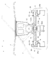
図1に示すように、物品搬送設備には、ループ状に形成された走行経路Rに沿って移動自在な搬送台車1を走行経路Rに沿って複数台連結した台車列Tと、搬送台車1に物品を受け渡す第1搬送部2と、搬送台車1から物品を受け取る第2搬送部3と、が設けられている。ちなみに、本実施形態では、物品は、スーツケースや旅行かばん等の大小様々な手荷物であり、物品搬送設備は、空港に設置されている。
Hereinafter, embodiments of the present invention will be described with reference to the drawings.
As shown in FIG. 1, the article transport facility includes a carriage train T in which a plurality of
そして、第1搬送部2は、走行経路Rに向けて下り傾斜する傾斜面を備えたベルトコンベヤ又はローラコンベヤ等の搬送装置にて構成されており、搬送装置の搬送作動により図中矢印で示す方向に移動させて第1搬送部2に隣接して位置する搬送台車1に物品を受け渡すように構成されている。
第2搬送部3は、走行経路Rに向けて上り傾斜する傾斜面を備えたスロープ又はローラコンベヤにて構成されており、物品をその自重により図中矢印で示す方向に移動させて第2搬送部3に隣接して位置する搬送台車1から受け取った物品を図外に向けて搬送するように構成されている。
第1搬送部2及び第2搬送部3の夫々は、走行経路Rに沿って複数設けられている。
And the
The 2nd conveyance part 3 is comprised by the slope or roller conveyor provided with the inclined surface which inclines and slopes toward the driving | running route R, and moves articles | goods in the direction shown by the arrow in the figure by the weight of the 2nd conveyance. The article received from the
A plurality of each of the
搬送台車1は、走行経路Rに沿って複数台連結されたループ状の台車列Tを形成しており、このループ状の台車列Tが走行経路Rに沿って移動するように構成されている。
そして、物品搬送設備は、複数の第1搬送部2のいずれかにて搬送された物品を、複数の搬送台車1のいずれかに受け渡し、物品を受け取った搬送台車1は、走行経路Rに沿って移動して、複数の第2搬送部3のいずれかに物品を受け渡すように構成されている。
The
Then, the article transport facility transfers the article transported by any of the plurality of
走行経路Rは、一対の直線水平部分R1と一対の曲線傾斜部分R2とを組み合わせてループ状に形成されている。一対の直線水平部分R1は互いに異なる高さに設定されており、一対の直線水平部分R1は、搬送台車1の走行方向に水平で且つ直線に設定されている。また、一対の曲線傾斜部分R2は、異なる高さの一対の直線水平部分R1を結ぶように、搬送台車1の走行方向に傾斜し且つ平面視で曲線に設定されている。このように、走行経路Rは、直線水平部分R1と、曲線傾斜部分R2と、を備えて構成されている。
The travel route R is formed in a loop shape by combining a pair of straight horizontal portions R1 and a pair of curved inclined portions R2. The pair of straight horizontal portions R1 are set at different heights, and the pair of straight horizontal portions R1 are set to be horizontal and straight in the traveling direction of the
ちなみに、直線水平部分R1は、搬送台車1が水平姿勢となる水平部分に相当し、曲線傾斜部分R2は、搬送台車1が前傾姿勢又は後傾姿勢となる傾斜部分に相当する。
また、図1上で上側に位置する直線経路が図1上で下側に位置する直線経路より高い位置に設定されている。そして、搬送台車1は図1上で走行経路Rを反時計回りに走行するため、図1上で右側に位置する曲線傾斜部分R2は上り傾斜、図1上で左側に位置する曲線傾斜部分R2は下り傾斜となっている。
Incidentally, the straight horizontal portion R1 corresponds to a horizontal portion where the
Further, the straight path located on the upper side in FIG. 1 is set at a position higher than the straight path located on the lower side in FIG. Since the
次に、搬送台車1について説明を加えるが、台車列Tを形成する複数台の搬送台車1の夫々は同様に構成されているため、1台の搬送台車1についてのみ説明する。
ちなみに、搬送台車1の走行方向に沿う方向を台車前後方向Xとし、その台車前後方向Xと直交する水平方向を台車横幅方向Yとして説明する。尚、搬送台車1の台車前後方向Xの前端部や台車前後方向Xの後端部の夫々を単に前端部や後端部と称する場合や、搬送台車1の台車横幅方向Yの両端部や台車横幅方向Yの中央部の夫々を単に両端部や中央部と称する場合がある等、台車前後方向Xや台車横幅方向Yを省略して説明する場合がある。
Next, although description is added about the
Incidentally, the direction along the traveling direction of the
図2に示すように、搬送台車1は、台車本体6と、その台車本体6の上方において台車本体6に支持された物品支持用の載置台7と、走行経路Rに沿って形成された走行面26a上を転動する車輪8と、台車本体6の台車横幅方向Yでの移動を規制する規制体9と、台車本体6の前端部に備えられた第1連結部10と、台車本体6の後端部に備えられた第2連結部11と、を備えている。
As shown in FIG. 2, the
〔載置台〕
図3に示すように、載置台7は、姿勢切換用モータ12の駆動により、支持用姿勢(実線で示す姿勢)と、支持用姿勢から台車前後方向Xに沿う軸心周りに揺動させた受渡用姿勢(仮想線で示す姿勢)と、に切換自在に構成されている。支持用姿勢は、載置台7上に物品を保持できる姿勢であり、搬送台車1は、載置台7を支持用姿勢とした状態で第1搬送部2から物品を受け取るようになっている。また、受渡用姿勢は、物品の自重により載置台7上で台車横幅方向Yに移動するように傾けた姿勢であり、搬送台車1は、載置台7を受渡用姿勢に切り換えて載置台7上の物品を第2搬送部3に受け渡すようになっている。
(Mounting table)
As shown in FIG. 3, the mounting table 7 is swung around the axis along the front-rear direction X of the carriage from the supporting attitude (the attitude shown by the solid line) and the supporting attitude by driving the
〔台車本体〕
図4に示すように、台車本体6は、台車横幅方向Yに沿う姿勢の横枠14と、台車前後方向Xに沿う姿勢の前後枠15と、を備えて構成されている。横枠14は、台車本体6における台車前後方向Xの前端部に備えられており、その横枠14の台車横幅方向Yの中央部と前後枠15の台車前後方向Xの前端部とが連結されている。つまり、台車本体6は、横枠14と前後枠15とで平面視形状がT字状に形成されている。
[Car body]
As shown in FIG. 4, the
また、横枠14は、台車横幅方向Yの中央部が台車横幅方向Yの両端部より後方に位置する屈曲形状に形成されている。具体的には、横枠14の中央部及び両端部は、平面視形状が台車横幅方向Yに沿う形状に形成されており、横枠14における中央部と両端部とを結ぶ部分は、平面視形状が台車横幅方向Yに対して傾斜する形状に形成されている。
このように横枠14を形成することで、台車本体6の前端部は、台車横幅方向Yの中央部が両端部より後方に位置する凹入形状に形成されている。
Further, the
By forming the
〔駆動装置〕
図5及び図6に示すように、搬送台車1には、台車前後方向Xに並ぶ状態で複数個の磁石(永久磁石)17が設けられており、地上側には、リニアモータ18が設けられている。台車列Tを走行経路Rに沿って移動させる駆動装置4は、これら複数個の磁石17とリニアモータ18とで構成されている。ちなみに、リニアモータ18として、リニア同期モータが設けられている。
[Driver]
As shown in FIGS. 5 and 6, the
図5に示すように、複数個の磁石17は、各磁石17の下面に生じる極性がS極、N極、S極というように交互となる状態で台車前後方向Xに並設されており、偶数個設けられている。
そして、図6に示すように、複数個の磁石17は、一列に並べた状態で長尺状のタッププレート19に固着されており、そのタッププレート19を台車前後方向Xに沿う姿勢で台車本体6の下面部に取り付けることで、台車本体6の下方に台車前後方向Xに一列に並ぶ状態で取り付けられている。
As shown in FIG. 5, the plurality of
As shown in FIG. 6, the plurality of
図7に示すように、タッププレート19は、台車本体6の下端部に形成された溝20を利用して取り付けられている。この溝20は、タッププレート19を台車前後方向Xの端部から挿入するためのプレート用蟻溝20aと、タッププレート19を固定するためのナット等の連結具21を台車前後方向Xの端部から挿入するための連結具用蟻溝20bとで形成されている。
プレート用蟻溝20aは、下方に開口する状態で台車本体6に形成されている。連結具用蟻溝20bは、プレート用蟻溝20aの上側に形成されており、プレート用蟻溝20aと連通する状態で台車本体6に形成されている。
そして、プレート用蟻溝20aにタッププレート19を挿入し、連結具用蟻溝20bに挿入した連結具21を用いてタッププレート19を台車本体6に固定するようになっている。
As shown in FIG. 7, the
The
Then, the
連結具用蟻溝20bは、台車横幅方向Yに複数に形成されているが、この複数の連結具用蟻溝20bの1つ又は2つ以上の連結具用蟻溝20bを用いて、タッププレート19を台車本体6に固定するようになっている。ちなみに、本実施形態では、連結具用蟻溝20bは3か所に形成されており、この3か所の連結具用蟻溝20bのうちの中央に位置する連結具用蟻溝20bのみを用いて、タッププレート19が台車本体6に固定されている。
The
台車本体6の後端部には、配線固定用のフレーム22が設けられている。このフレーム22は、前後枠15の後端部に前後枠15の上面から上方に突出する状態で設けられており、逆U字状に形成されている。そして、自車と後側に隣接する別の搬送台車1に亘って配設される給電用の給電線や通信用の通信線等の配線を、このフレーム22内を通して配設することで、配線が上下方向や台車横幅方向Yに散乱し難くなっている。
A
〔連結部〕
搬送台車1は、前側に隣接する別の搬送台車1、及び、後側に隣接する別の搬送台車1とは、連結ユニット24にて連結されている。この連結ユニット24は、搬送台車1の前端部に連結する第1連結部10と、搬送台車1の後端部に連結する第2連結部11と、で構成されている。
つまり、自車の前端部に連結ユニット24の第1連結部10を連結し且つ前側に隣接する別の搬送台車1の後端部に連結ユニット24の第2連結部11を連結することで、自車を前側に隣接する別の搬送台車1と連結するようになっている。また、自車の後端部に連結ユニット24の第2連結部11を連結し且つ後側に隣接する別の搬送台車1の前端部に連結ユニット24の第1連結部10を連結することで、自車を後側に隣接する別の搬送台車1と連結するようになっている。
(Connecting part)
The
That is, by connecting the first connecting
そして、連結ユニット24の第1連結部10と第2連結部11とは、上下方向に沿う第1台車揺動軸心P1周り及び台車横幅方向Yに沿う第2台車揺動軸心P2周りに揺動自在に連結されている。そのため、自車の前端部に連結した第1連結部10は、前方に隣接する別の搬送台車1の第2連結部11と第1台車揺動軸心P1周り及び第2台車揺動軸心P2周りに揺動自在に連結されている。尚、第1台車揺動軸心P1が、本発明の上下方向に沿う台車揺動軸心に相当する。
And the
第1連結部10は、台車本体6における台車横幅方向Yの中央部で且つ台車前後方向Xの前端部に備えられており、横枠14における台車横幅方向Yの中央部の上面に連結されている。このように設けられた第1連結部10は、複数個の磁石17のうちの最も前方に位置する磁石17と上下方向視で重複する状態で設けられている。
また、第2連結部11は、台車本体6における台車横幅方向Yの中央部で且つ台車前後方向Xの後端部に備えられており、前後枠15における後面に連結されている。
The first connecting
The second connecting
第1連結部10は、車輪8と第1台車揺動軸心P1とが台車横幅方向視で重複する範囲内で、台車本体6の前端部に対する連結位置を台車前後方向Xに調節できるように構成されている。
説明を加えると、連結ユニット24の第1連結部10には、ボルトやナット等を用いて台車本体6の前端部に連結するときに用いる連結孔(図示せず)が形成されている。この連結孔は、第1台車揺動軸心P1に対して台車前後方向Xにずれた位置に形成されている。具体的には、第1台車揺動軸心P1に対して、連結孔の中心が台車前後方向Xに0.5mmずれている。
The first connecting
If it demonstrates, the connection hole (not shown) used when connecting with the front-end part of the trolley | bogie
また、連結ユニット24は、図8に示す状態(通常状態と称する)から、連結ユニット24の全体を第2台車揺動軸心P2周りに180°回転させ、第2連結部11のみを第2台車揺動軸心P2周りに180°回転させた状態(反転状態と称する)でも、第1連結部10を自車における台車本体6の前端部に連結し且つ第2連結部11を前側に隣接する別の搬送台車1における台車本体6の後端部に連結できるようになっている。
In addition, the connecting
そして、反転状態とするべく、連結ユニット24の全体(第1連結部10)を第2台車揺動軸心P2周りに回転させることにより、連結孔が台車前後方向Xに移動する。そのため、通常状態と反転状態とで、第1連結部10の台車本体6に対する位置が台車前後方向Xに異なり、連結ユニット24を通常状態と反転状態とに切り換えることで、第1連結部10の台車本体6の前端部に対する連結位置を台車前後方向Xに調節できるようになっている。
Then, the connection hole is moved in the front-rear direction X of the carriage by rotating the entire connection unit 24 (first connection portion 10) around the second carriage swing axis P2 so as to be reversed. Therefore, the position of the first connecting
第1連結部10の連結位置を台車前後方向Xに調節することで、第1台車揺動軸心P1の位置も台車前後方向Xに移動するが、この第1台車揺動軸心P1の移動量は、連結孔の中心に対する第1台車揺動軸心P1のずれ量の2倍であり1mmであるため、第1連結部10の連結位置の調節は、車輪8と第1台車揺動軸心P1とが台車横幅方向視で重複する範囲内で行われる。
By adjusting the connecting position of the first connecting
〔車輪〕
搬送台車1は、搬送台車1が水平姿勢である状態(直線水平部分R1に位置している状態)において上下方向に沿う車輪揺動軸心P3周りに回転自在に台車本体6に連結されたキャスター枠25を備えている。そして、キャスター枠25が、車輪8の回転軸心である車輪回転軸心P4が車輪揺動軸心P3に対して水平方向に異なる位置となる状態で車輪8を回転自在に支持している。このように、車輪8の車輪回転軸心P4が車輪揺動軸心P3に対して水平方向に異なる位置としているため、搬送台車1の平面視での走行方向が直線水平部分R1と曲線傾斜部分R2とで変わるに伴って、車輪8の向きが変更されるようになっている。
〔Wheel〕
The
そして、キャスター枠25及びこれに支持された車輪8は、台車本体6における台車前後方向Xの前端部で且つ台車横幅方向Yの両端部の夫々に設けられている。
このようにキャスター枠25及び車輪8は台車本体6に一対設けられており、車輪8が転動する走行レール26も、一対の車輪8に対応して一対設けられている。一対の走行レール26の夫々は、走行経路Rに沿って設けられており、走行レール26の上面にて、車輪8が転動する走行面26aが形成されている。
The
Thus, a pair of caster frames 25 and
キャスター枠25は、車輪揺動軸心P3より後方に車輪回転軸心P4が位置し且つ車輪回転軸心P4が台車横幅方向Yに沿う姿勢となる直進走行状態(図2及び図3における姿勢)において、車輪8と第1連結部10の第1台車揺動軸心P1とが、台車横幅方向視で重複するように設けられている(図8参照)。つまり、直進走行状態において、平面視では第2台車揺動軸心P2の延長線上に車輪8の車輪回転軸心P4が位置しており、第1台車揺動軸心P1と車輪8とは、台車横幅方向視で重複するようになっている。
The
このように、車輪8を台車本体6の前端部に設けることで、前側に隣接する別の搬送台車1との連結が外れた場合でも、台車本体6の前端部は車輪8によって支持されていることで、台車本体6の前端部が落下することを回避できる。また、後側に隣接する別の搬送台車1との連結が外れた場合は、図11に示すように、台車本体6の姿勢は後傾姿勢となるため、台車本体6の前端部が通過した後、台車本体6の後端部が床面上の凹凸等に乗り上げることで、台車本体6が凹凸等に接触するにしても台車本体6が突っ張る状態で接触することを回避できる。
In this way, by providing the
そして、車輪8と第1連結部10の第1台車揺動軸心P1とが、台車横幅方向視で重複しており、搬送台車1が直線水平部分R1と曲線傾斜部分R2との接続部を走行するときに、車輪8が接続部を通過するタイミングと第1連結部10の第1台車揺動軸心P1が接続部を通過するタイミングとを近づけることができるため、第1連結部10が走行面26aに対して上下動し難くなり、搬送台車1を安定よく走行させることができる。
And the
〔規制体〕
搬送台車1には、走行レール26に接触して搬送台車1の台車横幅方向Yへの移動を規制する規制体9が設けられている。
この規制体9は、上下方向に沿う規制回転軸心P5周りに回転自在な回転体にて構成されており、走行レール26における台車横幅方向Yの内側の面に接触する状態で設けられている。なお、走行レール26は、走行経路Rに沿って設けられた案内レールに相当する。
[Regulatory body]
The
The restricting
規制体9は、台車本体6に対して着脱自在に設けられており、台車本体6には規制体9を取り付けるための孔27が前後方向に複数形成されている。そして、規制体9を台車本体6に対して装着する場合には装着対象の孔27を選択することで、直進走行状態において台車横幅方向視で車輪揺動軸心P3と重複する揺動重複箇所(図8(a)及び図9に示す箇所)と、直進走行状態において上下方向視で車輪回転軸心P4と重複する回転重複箇所(図10に示す箇所)と、直進走行状態において台車横幅方向視で車輪揺動軸心P3と車輪回転軸心P4との間に位置してこれら車輪揺動軸心P3と車輪回転軸心P4とのいずれとも重複しない中間箇所(図示省略)と、に台車前後方向Xでの規制体9の位置を変更自在に構成されている。
規制体9は、上下方向に沿う規制体回転軸心P5周りに回転自在に設けられている。
The restricting
The restricting
そして、図9に示すように、規制体9を揺動重複箇所に取り付けることで、規制体9と車輪揺動軸心P3とが近くなり、搬送台車1の走行方向が変わった場合でも、キャスター枠25の車輪揺動軸心P3周りでの揺動量を抑えることができる。そのため、車輪8が台車横幅方向Yに振れ難く、車輪8が走行レール26から脱輪し難くなる。
また、図10に示すように、規制体9を回転重複箇所に取り付けることで、搬送台車1が直線水平部分R1と曲線傾斜部分R2との接続部を走行するときに、車輪8が接続部を通過するタイミングと規制体9が接続部を通過するタイミングとを合わせることができるため、規制体9が走行面26aに対して上下動し難くなり、規制体9が走行レール26から上下方向に離脱し難くなる。
Then, as shown in FIG. 9, by attaching the restricting
Further, as shown in FIG. 10, by attaching the regulating
〔別実施形態〕
(1) 上記実施形態では、車輪回転軸心P4の延長線上に第1台車揺動軸心P1が位置するようにして、第1台車揺動軸心P1と車輪8とを、台車横幅方向視で重複させたが、車輪回転軸心P4を第1台車揺動軸心P1より台車前後方向Xで後方側に位置させながら、第1台車揺動軸心P1と車輪8とを、台車横幅方向視で重複させてもよく、また、車輪回転軸心P4を第1台車揺動軸心P1より台車前後方向Xで前方側に位置させながら、第1台車揺動軸心P1と車輪8とを、台車横幅方向視で重複させてもよい。
つまり、車輪8は、第1台車揺動軸心P1と台車横幅方向視で重複するように設ければよく、具体的には、車輪8の半径を50mmと仮定すれば、車輪回転軸心P4と第1台車揺動軸心P1との台車前後方向Xでのずれ量は50mm以下に抑えればよい。また、台車列Tにおける台車前後方向Xでの車輪8のピッチ(1200mm)を考慮すれば、車輪回転軸心P4と第1台車揺動軸心P1との台車前後方向Xでのずれ量は20mm以下に抑えることが望ましい。
[Another embodiment]
(1) In the embodiment described above, the first bogie rocking axis P1 and the
That is, the
(2) 上記実施形態では、台車本体6の前端部の形状を凹入形状としたが、台車本体6の形状は適宜変更してもよい。具体的には、例えば、横枠14を台車横幅方向Yに沿う直線状に形成して、台車本体6の前端部の形状を直線形状としてもよい。
この場合、第1連結部10を後方寄りに設けることで、車輪8と第1台車揺動軸心P1とを台車横幅方向視で重複させてもよく、また、車輪8を前方寄りに設けることで、車輪8と第1台車揺動軸心P1とを台車横幅方向視で重複させてもよい。
(2) In the above embodiment, the shape of the front end portion of the
In this case, by providing the first connecting
(3) 上記実施形態では、規制体9を、揺動重複箇所と中間箇所と回転重複箇所とに位置を変更自在に設けたが、規制体9を、これら3箇所のうちの2箇所に位置を変更自在に設ける、又は、3箇所のうちの1箇所に位置を変更不能に設けてもよい。具体的には、例えば、規制体9を、揺動重複箇所と回転重複箇所とにのみ位置を変更自在に設けてもよく、また、規制体9を、揺動重複箇所に位置変更不能に設けてもよい。
(3) In the said embodiment, although the
(4) 上記実施形態では、規制体9を、揺動重複箇所と中間箇所と回転重複箇所とに位置変更自在に設けたが、規制体9を、揺動重複箇所と中間箇所と回転重複箇所との位置のいずれか2箇所に位置変更自在に設けてもよく、また、規制体9を、揺動重複箇所と中間箇所と回転重複箇所との位置のいずれか1箇所に位置変更不能に設けてもよい。
(4) In the above-described embodiment, the regulating
(5) 上記実施形態では、走行経路Rの形状をループ状とし、搬送台車1を一方向に移動させたが、走行経路Rの形状を有端状とし、搬送台車1を往復走行させてもよい。
また、上記実施形態では、走行経路Rを直線部分と曲線部分とを組み合わせて構成したが、走行経路Rをループ状とした場合には曲線部分のみにて構成してもよく、走行経路Rを有端状とした場合には直線部分のみにて構成してもよい。
要するに、上記実施形態では、直線水平部分R1と曲線傾斜部分R2とを組み合わせて走行経路Rを形成したが、直線水平部分R1、曲線傾斜部分R2、搬送台車1の走行方向に水平で且つ平面視で曲線に設定された曲線水平部分、及び、搬送台車1の走行方向に傾斜し且つ平面視で直線に設定された直線傾斜部分、を適宜組み合わせて走行経路Rを形成してもよい。
(5) In the above embodiment, the shape of the travel path R and looped, but moves the
Moreover, in the said embodiment, although the driving | running route R was comprised combining the linear part and the curve part, when the driving | running route R is made into a loop shape, you may comprise only by a curve part, In the case of an end shape, it may be constituted by only a straight portion.
In short, in the above-described embodiment, the travel route R is formed by combining the straight horizontal portion R1 and the curved slope portion R2, but the straight horizontal portion R1, the curved slope portion R2, and the
(6) 上記実施形態では、走行経路Rに沿って走行レール26を設け、その走行レール26の上面を、車輪8が転動する走行面26aとしたが、走行レール26を設けずに、床の上面を、車輪8が転動する走行面26aとしてもよい。
また、上記実施形態では、走行レール26の側面に規制体9を接触させるようにして、走行レール26を案内レールに兼用させたが、走行レール26とは別に案内レールを設けてもよい。
(6) In the above embodiment, the
In the above embodiment, the restricting
(7) 上記実施形態では、車輪8を車輪揺動軸心P3周りに揺動自在に設けたが、車輪8を揺動不能に設けてもよい。
(7) In the above embodiment, the
(8) 上記実施形態では、第1連結部10の台車本体6の前端部に対する連結位置を台車前後方向Xに調節することで、自車の台車本体6と前方に隣接する別の搬送台車1の台車本体6との間隔を調節したが、第2連結部11の台車本体6の後端部に対する連結位置を台車前後方向Xに調節することで、自車の台車本体6と前方に隣接する別の搬送台車1の台車本体6との間隔を調節してもよい。
また、第1連結部10の台車本体6の前端部に対する連結位置の調整量を1mmとしたが、この調整量は、例えば、0.1mm〜10mmの範囲内で適宜設定すればよく、第1連結部10の連結位置を調整することで、前記車輪と前記台車揺動軸心とが台車横幅方向視で重複する範囲から外れない調整量であればよい。
(8) In the above-described embodiment, by adjusting the connecting position of the first connecting
Moreover, although the adjustment amount of the connection position with respect to the front-end part of the cart
1 搬送台車
4 駆動装置
6 台車本体
8 車輪
9 規制体
10 第1連結部
11 第2連結部
25 キャスター枠
26 走行レール(案内レール)
26a 走行面
R 走行経路
R1 水平部分
R2 傾斜部分
T 台車列
P1 台車揺動軸心
P3 車輪揺動軸心
P4 車輪回転軸心
X 台車前後方向
Y 台車横幅方向
DESCRIPTION OF
26a Traveling surface R Traveling path R1 Horizontal part R2 Inclined part T Car train P1 Car swing axis P3 Wheel swing axis P4 Wheel rotation axis X Carriage longitudinal direction Y Car lateral direction
Claims (8)
前記台車列を前記走行経路に沿って移動させる駆動装置と、が設けられ、
前記複数台の搬送台車の夫々が、台車本体と、前記走行経路に沿って形成された走行面上を転動する車輪と、前記台車本体の前端部に備えられた第1連結部と、前記台車本体の後端部に備えられた第2連結部と、を備え、
前記第1連結部が、前方に隣接する別の搬送台車の前記第2連結部と上下方向に沿う台車揺動軸心周りに揺動自在に連結される物品搬送設備であって、
前記車輪が、前記台車本体の前端部に設けられ、
前記車輪と前記第1連結部の前記台車揺動軸心とが、台車横幅方向視で重複し、
前記複数台の搬送台車の夫々が、前記搬送台車が水平姿勢である状態において上下方向に沿う車輪揺動軸心周りに回転自在に前記台車本体に連結されたキャスター枠を備え、
前記キャスター枠が、前記車輪の回転軸心である車輪回転軸心が前記車輪揺動軸心に対して水平方向に異なる位置となる状態で前記車輪を回転自在に支持し、
前記キャスター枠が、前記車輪揺動軸心より後方に前記車輪回転軸心が位置し且つ前記車輪回転軸心が台車横幅方向に沿う姿勢となる直進走行状態において、前記車輪と前記台車揺動軸心とが、台車横幅方向視で重複し、
前記複数の搬送台車の夫々が、前記走行経路に沿って設けられた案内レールに接触して前記台車本体の台車横幅方向への移動を規制する規制体を備え、
前記規制体は、上下方向に沿う規制体回転軸心周りに回転自在で設けられ、且つ、前記直進走行状態において、前記規制体回転軸心が台車前後方向で前記車輪回転軸心と前記車輪揺動軸心との間に位置する物品搬送設備。 A carriage row in which a plurality of carriages for conveying articles that are movable along a travel path are connected along the travel path;
A drive device for moving the carriage train along the travel route, and
Each of the plurality of transport carts is a cart body, wheels that roll on a travel surface formed along the travel route, a first connecting portion provided at a front end of the cart body, A second connecting part provided at the rear end of the carriage body,
The first connection part is an article transfer facility that is swingably connected to the second connection part of another transfer carriage adjacent to the front and swinging about a carriage swing axis along the vertical direction,
The wheel is provided at a front end of the carriage body;
The wheel and the bogie rocking axis of the first connecting portion overlap with each other in the bogie width direction view,
Each of the plurality of transport carts includes a caster frame coupled to the cart body so as to be rotatable around a wheel swing axis along the vertical direction in a state where the transport cart is in a horizontal posture.
The caster frame rotatably supports the wheel in a state where a wheel rotation axis that is a rotation axis of the wheel is in a different position in the horizontal direction with respect to the wheel swing axis,
When the caster frame is in a straight traveling state in which the wheel rotation axis is positioned behind the wheel swing axis and the wheel rotation axis is in a posture along the horizontal direction of the carriage, the wheel and the carriage swing shaft The mind overlaps in the horizontal direction of the carriage,
Each of the plurality of transport carts includes a regulating body that contacts a guide rail provided along the travel route and regulates movement of the cart body in the cart lateral width direction,
The restricting body is rotatably provided around a restricting body rotation axis along the vertical direction, and in the straight traveling state, the restricting body rotation axis is in the longitudinal direction of the carriage and the wheel rotation axis and the wheel swing Goods transportation equipment located between the axis of movement .
前記台車列を前記走行経路に沿って移動させる駆動装置と、が設けられ、
前記複数台の搬送台車の夫々が、台車本体と、前記走行経路に沿って形成された走行面上を転動する車輪と、前記台車本体の前端部に備えられた第1連結部と、前記台車本体の後端部に備えられた第2連結部と、を備え、
前記第1連結部が、前方に隣接する別の搬送台車の前記第2連結部と上下方向に沿う台車揺動軸心周りに揺動自在に連結される物品搬送設備であって、
前記車輪が、前記台車本体の前端部に設けられ、
前記車輪と前記第1連結部の前記台車揺動軸心とが、台車横幅方向視で重複し、
前記複数台の搬送台車の夫々が、前記搬送台車が水平姿勢である状態において上下方向に沿う車輪揺動軸心周りに回転自在に前記台車本体に連結されたキャスター枠を備え、
前記キャスター枠が、前記車輪の回転軸心である車輪回転軸心が前記車輪揺動軸心に対して水平方向に異なる位置となる状態で前記車輪を回転自在に支持し、
前記キャスター枠が、前記車輪揺動軸心より後方に前記車輪回転軸心が位置し且つ前記車輪回転軸心が台車横幅方向に沿う姿勢となる直進走行状態において、前記車輪と前記台車揺動軸心とが、台車横幅方向視で重複し、
前記走行経路に沿って設けられて上面にて前記走行面を形成する走行レールが設けられ、
前記複数の搬送台車の夫々が、前記走行経路に沿って設けられた案内レールに接触して前記台車本体の台車横幅方向への移動を規制する規制体を備え、
前記規制体が、前記直進走行状態において台車横幅方向視で前記車輪揺動軸心と重複する揺動重複箇所に設けられ、
前記規制体が、前記揺動重複箇所と、前記直進走行状態において上下方向視で前記車輪回転軸心と重複する回転重複箇所と、に台車前後方向での位置を変更自在に設けられている物品搬送設備。 A carriage row in which a plurality of carriages for conveying articles that are movable along a travel path are connected along the travel path;
A drive device for moving the carriage train along the travel route, and
Each of the plurality of transport carts is a cart body, wheels that roll on a travel surface formed along the travel route, a first connecting portion provided at a front end of the cart body, A second connecting part provided at the rear end of the carriage body,
The first connection part is an article transfer facility that is swingably connected to the second connection part of another transfer carriage adjacent to the front and swinging about a carriage swing axis along the vertical direction,
The wheel is provided at a front end of the carriage body;
The wheel and the bogie rocking axis of the first connecting portion overlap with each other in the bogie width direction view,
Each of the plurality of transport carts includes a caster frame coupled to the cart body so as to be rotatable around a wheel swing axis along the vertical direction in a state where the transport cart is in a horizontal posture.
The caster frame rotatably supports the wheel in a state where a wheel rotation axis that is a rotation axis of the wheel is in a different position in the horizontal direction with respect to the wheel swing axis,
When the caster frame is in a straight traveling state in which the wheel rotation axis is positioned behind the wheel swing axis and the wheel rotation axis is in a posture along the horizontal direction of the carriage, the wheel and the carriage swing shaft The mind overlaps in the horizontal direction of the carriage,
A travel rail provided along the travel path to form the travel surface on an upper surface;
Each of the plurality of transport carts includes a regulating body that contacts a guide rail provided along the travel route and regulates movement of the cart body in the cart lateral width direction,
The restricting body is provided at a swing overlapping portion that overlaps the wheel swing axis when viewed in the lateral direction of the carriage in the straight traveling state;
An article in which the restricting body is provided in such a manner that the position in the front-rear direction of the carriage can be changed at the swing overlapping part and the rotation overlapping part overlapping the wheel rotation axis when viewed in the vertical direction in the straight traveling state. Transport equipment.
前記台車列を前記走行経路に沿って移動させる駆動装置と、が設けられ、
前記複数台の搬送台車の夫々が、台車本体と、前記走行経路に沿って形成された走行面上を転動する車輪と、前記台車本体の前端部に備えられた第1連結部と、前記台車本体の後端部に備えられた第2連結部と、を備え、
前記第1連結部が、前方に隣接する別の搬送台車の前記第2連結部と上下方向に沿う台車揺動軸心周りに揺動自在に連結される物品搬送設備であって、
前記車輪が、前記台車本体の前端部に設けられ、
前記車輪と前記第1連結部の前記台車揺動軸心とが、台車横幅方向視で重複し、
前記複数台の搬送台車の夫々が、前記搬送台車が水平姿勢である状態において上下方向に沿う車輪揺動軸心周りに回転自在に前記台車本体に連結されたキャスター枠を備え、
前記キャスター枠が、前記車輪の回転軸心である車輪回転軸心が前記車輪揺動軸心に対して水平方向に異なる位置となる状態で前記車輪を回転自在に支持し、
前記キャスター枠が、前記車輪揺動軸心より後方に前記車輪回転軸心が位置し且つ前記車輪回転軸心が台車横幅方向に沿う姿勢となる直進走行状態において、前記車輪と前記台車揺動軸心とが、台車横幅方向視で重複し、
前記複数の搬送台車の夫々が、前記走行経路に沿って設けられた案内レールに接触して前記台車本体の台車横幅方向への移動を規制する規制体を備え、
前記規制体が、上下方向視で前記車輪回転軸心と重複する回転重複箇所に設けられている物品搬送設備。 A carriage row in which a plurality of carriages for conveying articles that are movable along a travel path are connected along the travel path;
A drive device for moving the carriage train along the travel route, and
Each of the plurality of transport carts is a cart body, wheels that roll on a travel surface formed along the travel route, a first connecting portion provided at a front end of the cart body, A second connecting part provided at the rear end of the carriage body,
The first connection part is an article transfer facility that is swingably connected to the second connection part of another transfer carriage adjacent to the front and swinging about a carriage swing axis along the vertical direction,
The wheel is provided at a front end of the carriage body;
The wheel and the bogie rocking axis of the first connecting portion overlap with each other in the bogie width direction view,
Each of the plurality of transport carts includes a caster frame coupled to the cart body so as to be rotatable around a wheel swing axis along the vertical direction in a state where the transport cart is in a horizontal posture.
The caster frame rotatably supports the wheel in a state where a wheel rotation axis that is a rotation axis of the wheel is in a different position in the horizontal direction with respect to the wheel swing axis,
When the caster frame is in a straight traveling state in which the wheel rotation axis is positioned behind the wheel swing axis and the wheel rotation axis is in a posture along the horizontal direction of the carriage, the wheel and the carriage swing shaft The mind overlaps in the horizontal direction of the carriage,
Each of the plurality of transport carts includes a regulating body that contacts a guide rail provided along the travel route and regulates movement of the cart body in the cart lateral width direction,
The article conveying facility , wherein the restricting body is provided at a rotation overlap portion overlapping with the wheel rotation axis when viewed in the vertical direction .
前記第1連結部が、前記台車本体における台車横幅方向の中央部に備えられ、
前記台車本体の前端部が、台車横幅方向の中央部が前記両端部より後方に位置する凹入形状に形成されている請求項1から3のいずれか一項に記載の物品搬送設備。 The caster frame is provided at each of both ends of the cart body in the cart width direction,
The first connecting portion is provided in a central portion of the cart body in the cart lateral width direction,
The article conveyance facility according to any one of claims 1 to 3, wherein a front end portion of the carriage main body is formed in a recessed shape in which a central portion in the carriage lateral width direction is located rearward of the both end portions.
前記台車列を前記走行経路に沿って移動させる駆動装置と、が設けられ、
前記複数台の搬送台車の夫々が、台車本体と、前記走行経路に沿って形成された走行面上を転動する車輪と、前記台車本体の前端部に備えられた第1連結部と、前記台車本体の後端部に備えられた第2連結部と、を備え、
前記第1連結部が、前方に隣接する別の搬送台車の前記第2連結部と上下方向に沿う台車揺動軸心周りに揺動自在に連結される物品搬送設備であって、
前記車輪が、前記台車本体の前端部に設けられ、
前記車輪と前記第1連結部の前記台車揺動軸心とが、台車横幅方向視で重複し、
前記第1連結部が、前記車輪と前記台車揺動軸心とが台車横幅方向視で重複する範囲内で、前記台車本体の前端部に対する連結位置を台車前後方向に調節できるように構成されている物品搬送設備。 A carriage row in which a plurality of carriages for conveying articles that are movable along a travel path are connected along the travel path;
A drive device for moving the carriage train along the travel route, and
Each of the plurality of transport carts is a cart body, wheels that roll on a travel surface formed along the travel route, a first connecting portion provided at a front end of the cart body, A second connecting part provided at the rear end of the carriage body,
The first connection part is an article transfer facility that is swingably connected to the second connection part of another transfer carriage adjacent to the front and swinging about a carriage swing axis along the vertical direction,
The wheel is provided at a front end of the carriage body;
The wheel and the bogie rocking axis of the first connecting portion overlap with each other in the bogie width direction view,
The first connecting portion is configured such that the connecting position with respect to the front end portion of the carriage main body can be adjusted in the longitudinal direction of the carriage within a range in which the wheel and the carriage swing axis overlap with each other when viewed in the transverse direction of the carriage. article transport facility it is.
Priority Applications (13)
| Application Number | Priority Date | Filing Date | Title |
|---|---|---|---|
| JP2013074846A JP6094331B2 (en) | 2013-03-29 | 2013-03-29 | Goods transport equipment |
| CN201480019333.7A CN105102353B (en) | 2013-03-29 | 2014-03-28 | Article carrying apparatus |
| DK14772557.6T DK2979998T3 (en) | 2013-03-29 | 2014-03-28 | Article Transportanlæg |
| EP14772557.6A EP2979998B1 (en) | 2013-03-29 | 2014-03-28 | Article transport facility |
| PCT/JP2014/059192 WO2014157640A1 (en) | 2013-03-29 | 2014-03-28 | Article transport facility |
| US14/781,147 US9376271B2 (en) | 2013-03-29 | 2014-03-28 | Article transport facility |
| CA3145590A CA3145590A1 (en) | 2013-03-29 | 2014-03-28 | Article transport facility |
| CA2908413A CA2908413C (en) | 2013-03-29 | 2014-03-28 | Article transport facility |
| AU2014244977A AU2014244977B2 (en) | 2013-03-29 | 2014-03-28 | Article transport facility |
| CA3145600A CA3145600A1 (en) | 2013-03-29 | 2014-03-28 | Article transport facility |
| SG11201507678TA SG11201507678TA (en) | 2013-03-29 | 2014-03-28 | Article transport facility |
| MYPI2015703271A MY170115A (en) | 2013-03-29 | 2014-03-28 | Article transport facility |
| ES14772557T ES2706175T3 (en) | 2013-03-29 | 2014-03-28 | Installation for transportation of articles |
Applications Claiming Priority (1)
| Application Number | Priority Date | Filing Date | Title |
|---|---|---|---|
| JP2013074846A JP6094331B2 (en) | 2013-03-29 | 2013-03-29 | Goods transport equipment |
Publications (2)
| Publication Number | Publication Date |
|---|---|
| JP2014198620A JP2014198620A (en) | 2014-10-23 |
| JP6094331B2 true JP6094331B2 (en) | 2017-03-15 |
Family
ID=51624596
Family Applications (1)
| Application Number | Title | Priority Date | Filing Date |
|---|---|---|---|
| JP2013074846A Active JP6094331B2 (en) | 2013-03-29 | 2013-03-29 | Goods transport equipment |
Country Status (11)
| Country | Link |
|---|---|
| US (1) | US9376271B2 (en) |
| EP (1) | EP2979998B1 (en) |
| JP (1) | JP6094331B2 (en) |
| CN (1) | CN105102353B (en) |
| AU (1) | AU2014244977B2 (en) |
| CA (3) | CA3145600A1 (en) |
| DK (1) | DK2979998T3 (en) |
| ES (1) | ES2706175T3 (en) |
| MY (1) | MY170115A (en) |
| SG (1) | SG11201507678TA (en) |
| WO (1) | WO2014157640A1 (en) |
Families Citing this family (14)
| Publication number | Priority date | Publication date | Assignee | Title |
|---|---|---|---|---|
| EP3313757B1 (en) * | 2015-06-24 | 2020-11-11 | Beumer Group A/S | Line sorter |
| ITUB20161148A1 (en) * | 2016-02-29 | 2017-08-29 | Vismunda Srl | HANDLING SYSTEM WITH INDEPENDENT AND COORDINATED SHUTTLES, FOR INDUSTRIAL AUTOMATION |
| WO2017150005A1 (en) * | 2016-03-03 | 2017-09-08 | 村田機械株式会社 | Conveyance system |
| DE102016106621A1 (en) | 2016-04-11 | 2017-10-12 | Weber Maschinenbau Gmbh Breidenbach | Device, transport movers and transport moversystem |
| JP6848373B2 (en) | 2016-11-14 | 2021-03-24 | 株式会社ダイフク | Goods transport equipment |
| US10450142B1 (en) * | 2018-04-26 | 2019-10-22 | Intelligrated Headquarters, Llc | Conveyor carrier cart |
| JP1619663S (en) * | 2018-04-27 | 2018-12-03 | ||
| JP6823833B2 (en) * | 2018-04-27 | 2021-02-03 | 株式会社ダイフク | Transport sorting device |
| EP3575250A1 (en) * | 2018-05-30 | 2019-12-04 | B&R Industrial Automation GmbH | Method for operating a conveying device in the form of a long stator linear motor |
| DE102018211839A1 (en) * | 2018-07-17 | 2020-01-23 | Bausch + Ströbel Maschinenfabrik Ilshofen GmbH + Co. KG | transport system |
| JP7192282B2 (en) * | 2018-07-23 | 2022-12-20 | 村田機械株式会社 | Article conveying device |
| US10532895B1 (en) | 2018-08-20 | 2020-01-14 | Intelligrated Headquarters, Llc | Cart coupling assembly |
| JP7040487B2 (en) * | 2019-03-20 | 2022-03-23 | 株式会社ダイフク | Goods transport equipment |
| JP7468484B2 (en) * | 2021-09-03 | 2024-04-16 | 株式会社ダイフク | Goods transport vehicle |
Family Cites Families (22)
| Publication number | Priority date | Publication date | Assignee | Title |
|---|---|---|---|---|
| DE595168C (en) * | 1934-04-03 | Eisenwerk Weserhuette Akt Ges | Apron conveyor | |
| DE602733C (en) * | 1934-09-15 | Eisenwerk Weserhuette Akt Ges | Conveyor car train running on rails | |
| DE606020C (en) * | 1934-11-23 | Eva Anna Gertrud Bruns | Apron conveyor | |
| DE837068C (en) * | 1949-12-11 | 1952-04-21 | Hauhinco Maschf | Link conveyor belt |
| DE945014C (en) * | 1952-07-05 | 1956-06-28 | Konrad Grebe | Conveyor belt with cross members |
| DE1148182B (en) * | 1956-09-26 | 1963-05-02 | Wilhelm Becker | Conveyor belt pull |
| FR1574831A (en) * | 1968-05-06 | 1969-07-18 | ||
| GB2025343A (en) * | 1978-05-23 | 1980-01-23 | Cosan Crisplant As | Sorting tray-type conveyor |
| US5054601A (en) * | 1989-09-19 | 1991-10-08 | Quipp, Incorporated | Sorting conveyor |
| JP2856033B2 (en) * | 1993-07-16 | 1999-02-10 | 株式会社ダイフク | Transport equipment using moving objects |
| CH687616A5 (en) * | 1994-06-08 | 1997-01-15 | Grapha Holding Ag | Pram chain for a sorting system. |
| GB2300612B (en) * | 1995-04-25 | 1998-09-30 | Crisplant As | Conveyor |
| AU5312298A (en) * | 1997-01-06 | 1998-08-03 | Crisplant A/S | A cart unit |
| GB0023370D0 (en) * | 2000-09-23 | 2000-11-08 | Logan Fabricom Ltd | A material sortation system |
| JP4538774B2 (en) * | 2001-02-14 | 2010-09-08 | 株式会社ダイフク | Carriage transfer device |
| JP4240843B2 (en) * | 2001-04-27 | 2009-03-18 | 村田機械株式会社 | Tracked cart system |
| US6736254B1 (en) * | 2002-05-14 | 2004-05-18 | Mantissa Corporation | Off-set block tilt tray sorter with gap detector |
| JP4310733B2 (en) * | 2003-09-08 | 2009-08-12 | 株式会社ダイフク | Friction-driven cart type conveyor |
| NL1026137C2 (en) * | 2004-05-07 | 2005-11-08 | Vanderlande Ind Nederland | Device for sorting products. |
| JP4811707B2 (en) | 2005-09-16 | 2011-11-09 | 日本精工株式会社 | Rotating electric machine |
| JP4978371B2 (en) * | 2007-08-24 | 2012-07-18 | 株式会社ダイフク | Conveyor using trolley |
| JP5626842B2 (en) * | 2010-03-30 | 2014-11-19 | 三機工業株式会社 | Sorting conveyor with cross sorter |
-
2013
- 2013-03-29 JP JP2013074846A patent/JP6094331B2/en active Active
-
2014
- 2014-03-28 WO PCT/JP2014/059192 patent/WO2014157640A1/en active Application Filing
- 2014-03-28 AU AU2014244977A patent/AU2014244977B2/en active Active
- 2014-03-28 EP EP14772557.6A patent/EP2979998B1/en active Active
- 2014-03-28 ES ES14772557T patent/ES2706175T3/en active Active
- 2014-03-28 CA CA3145600A patent/CA3145600A1/en active Pending
- 2014-03-28 SG SG11201507678TA patent/SG11201507678TA/en unknown
- 2014-03-28 MY MYPI2015703271A patent/MY170115A/en unknown
- 2014-03-28 DK DK14772557.6T patent/DK2979998T3/en active
- 2014-03-28 CN CN201480019333.7A patent/CN105102353B/en active Active
- 2014-03-28 US US14/781,147 patent/US9376271B2/en active Active
- 2014-03-28 CA CA2908413A patent/CA2908413C/en active Active
- 2014-03-28 CA CA3145590A patent/CA3145590A1/en active Pending
Also Published As
| Publication number | Publication date |
|---|---|
| CA3145590A1 (en) | 2014-10-02 |
| CN105102353B (en) | 2017-06-23 |
| CN105102353A (en) | 2015-11-25 |
| EP2979998A1 (en) | 2016-02-03 |
| US9376271B2 (en) | 2016-06-28 |
| CA2908413A1 (en) | 2014-10-02 |
| SG11201507678TA (en) | 2015-10-29 |
| AU2014244977A1 (en) | 2015-10-15 |
| EP2979998A4 (en) | 2016-11-16 |
| WO2014157640A1 (en) | 2014-10-02 |
| CA2908413C (en) | 2022-09-27 |
| AU2014244977B2 (en) | 2017-06-29 |
| JP2014198620A (en) | 2014-10-23 |
| ES2706175T3 (en) | 2019-03-27 |
| MY170115A (en) | 2019-07-05 |
| US20160046453A1 (en) | 2016-02-18 |
| EP2979998B1 (en) | 2018-10-17 |
| CA3145600A1 (en) | 2014-10-02 |
| DK2979998T3 (en) | 2019-02-04 |
Similar Documents
| Publication | Publication Date | Title |
|---|---|---|
| JP6094331B2 (en) | Goods transport equipment | |
| JP6278341B2 (en) | Goods transport equipment | |
| TWI564987B (en) | Article transport facility | |
| KR101736887B1 (en) | Item conveyance infrastructure | |
| CN102923427A (en) | Article transport equipment | |
| KR20130070543A (en) | Ceilling installation type article transport facility | |
| JP4483055B2 (en) | Transport equipment | |
| JP4240758B2 (en) | Transport equipment | |
| US20230373725A1 (en) | Carrier basket support and stabilizing system for carrier basket transporter | |
| JP2021195063A (en) | Conveyance carriage and conveyance carriage system | |
| JP3622953B2 (en) | Link frame connection mechanism of tray-type article transport device | |
| JP2936940B2 (en) | Transport equipment using self-propelled trolley | |
| JP3411268B2 (en) | Conveyor cart type conveying system | |
| JP2020182390A (en) | Seedling raising box arranging unit and seedling raising box arranging method | |
| JP5754650B2 (en) | Frictional drive device | |
| JP2753819B2 (en) | Article sorting equipment | |
| JP2018184290A (en) | Conveyor device | |
| JP4541261B2 (en) | Tracked unmanned transport cart | |
| JP3086461U (en) | Transport device and traveling body | |
| KR20230069323A (en) | Rail type high speed sorting transfe vehicle | |
| JP2000327125A (en) | Carrying device | |
| JP2004114772A (en) | Truck conveyor | |
| JP6065282B2 (en) | Conveyor equipment using a linked cart | |
| JP2002264802A (en) | Load carrying facility | |
| JP2004067032A (en) | Article carrying appliance |
Legal Events
| Date | Code | Title | Description |
|---|---|---|---|
| A621 | Written request for application examination |
Free format text: JAPANESE INTERMEDIATE CODE: A621 Effective date: 20150223 |
|
| A131 | Notification of reasons for refusal |
Free format text: JAPANESE INTERMEDIATE CODE: A131 Effective date: 20160315 |
|
| A02 | Decision of refusal |
Free format text: JAPANESE INTERMEDIATE CODE: A02 Effective date: 20160809 |
|
| A521 | Request for written amendment filed |
Free format text: JAPANESE INTERMEDIATE CODE: A523 Effective date: 20161109 |
|
| A911 | Transfer to examiner for re-examination before appeal (zenchi) |
Free format text: JAPANESE INTERMEDIATE CODE: A911 Effective date: 20161124 |
|
| TRDD | Decision of grant or rejection written | ||
| A01 | Written decision to grant a patent or to grant a registration (utility model) |
Free format text: JAPANESE INTERMEDIATE CODE: A01 Effective date: 20170117 |
|
| A61 | First payment of annual fees (during grant procedure) |
Free format text: JAPANESE INTERMEDIATE CODE: A61 Effective date: 20170130 |
|
| R150 | Certificate of patent or registration of utility model |
Ref document number: 6094331 Country of ref document: JP Free format text: JAPANESE INTERMEDIATE CODE: R150 |
|
| R250 | Receipt of annual fees |
Free format text: JAPANESE INTERMEDIATE CODE: R250 |
|
| R250 | Receipt of annual fees |
Free format text: JAPANESE INTERMEDIATE CODE: R250 |
|
| R250 | Receipt of annual fees |
Free format text: JAPANESE INTERMEDIATE CODE: R250 |
|
| R250 | Receipt of annual fees |
Free format text: JAPANESE INTERMEDIATE CODE: R250 |
|
| R250 | Receipt of annual fees |
Free format text: JAPANESE INTERMEDIATE CODE: R250 |