JP6089956B2 - Information processing apparatus, control method, and control program - Google Patents
Information processing apparatus, control method, and control program Download PDFInfo
- Publication number
- JP6089956B2 JP6089956B2 JP2013106092A JP2013106092A JP6089956B2 JP 6089956 B2 JP6089956 B2 JP 6089956B2 JP 2013106092 A JP2013106092 A JP 2013106092A JP 2013106092 A JP2013106092 A JP 2013106092A JP 6089956 B2 JP6089956 B2 JP 6089956B2
- Authority
- JP
- Japan
- Prior art keywords
- unit
- information
- identification information
- storage unit
- information processing
- Prior art date
- Legal status (The legal status is an assumption and is not a legal conclusion. Google has not performed a legal analysis and makes no representation as to the accuracy of the status listed.)
- Expired - Fee Related
Links
Images


Landscapes
- Fittings On The Vehicle Exterior For Carrying Loads, And Devices For Holding Or Mounting Articles (AREA)
Description
本発明は、情報処理装置,制御方法及び制御プログラムに関する。 The present invention relates to an information processing apparatus, a control method, and a control program.
例えば、カーナビゲーションシステムや業務用装置等の車載装置は、不正に車両から取り外され盗難されるおそれがある。車載装置においては、その記憶装置に機密情報が格納されているものもある。そこで、車載装置内の機密情報の漏洩を防止する手法が求められている。
従来においては、例えば、無線通信機能を用いて、遠隔操作により車載装置内の情報を削除等する手法が知られている。
For example, in-vehicle devices such as car navigation systems and business devices may be illegally removed from the vehicle and stolen. Some in-vehicle devices store confidential information in the storage device. Therefore, a technique for preventing leakage of confidential information in the in-vehicle device is required.
Conventionally, for example, a method of deleting information in an in-vehicle device by remote operation using a wireless communication function is known.
しかしながら、このような従来の車載装置においては、遠隔操作による車載装置の情報の削除は、盗難発生が検知されてから行なわれるので即応性に欠け、情報の漏洩を確実に阻止することができないという課題がある。
1つの側面では、本発明は情報の漏洩を阻止できるようにすることを目的とする。
なお、前記目的に限らず、後述する発明を実施するための形態に示す各構成により導かれる作用効果であって、従来の技術によっては得られない作用効果を奏することも本発明の他の目的の1つとして位置付けることができる。
However, in such a conventional vehicle-mounted device, the deletion of information on the vehicle-mounted device by remote operation is performed after the occurrence of theft is detected, so that it is not responsive and cannot reliably prevent information leakage. There are challenges.
In one aspect, an object of the present invention is to prevent information leakage.
In addition, the present invention is not limited to the above-described object, and other effects of the present invention can be achieved by the functions and effects derived from the respective configurations shown in the embodiments for carrying out the invention which will be described later. It can be positioned as one of
このため、この情報処理装置は、情報が格納された情報処理装置であって、当該情報処理装置の起動過程において、前記情報の読み出しを禁止する禁止制御部と、1以上の電子装置と接続可能な接続部と、前記接続部を介した前記電子装置の着脱操作を監視する監視部と、前記監視部が監視した前記着脱操作が予め規定された基準操作パターンと一致した場合に、規定操作が行なわれたことを示す識別情報を不揮発性記憶部に格納する格納処理部と、当該情報処理装置の起動過程において、前記不揮発性記憶部から前記識別情報を読み出した場合に、前記禁止制御部による前記情報の読み出し禁止を抑止する抑止部とを備える。 For this reason, the information processing apparatus is an information processing apparatus in which information is stored, and can be connected to a prohibition control unit that prohibits reading of the information and one or more electronic devices in the startup process of the information processing apparatus A connecting unit, a monitoring unit that monitors the attaching / detaching operation of the electronic device via the connecting unit, and the attaching / detaching operation monitored by the monitoring unit matches a predetermined reference operation pattern. When the identification information is read from the non-volatile storage unit in the startup process of the information processing apparatus, the storage processing unit that stores the identification information indicating that it has been performed by the prohibition control unit A deterrence unit for deterring prohibition of reading of the information.
一実施形態によれば、情報の漏洩を阻止することができる。 According to one embodiment, information leakage can be prevented.
以下、図面を参照して本情報処理装置,制御方法及び制御プログラムに係る実施の形態を説明する。ただし、以下に示す実施形態はあくまでも例示に過ぎず、実施形態で明示しない種々の変形例や技術の適用を排除する意図はない。すなわち、本実施形態を、その趣旨を逸脱しない範囲で種々変形(実施形態及び各変形例を組み合わせる等)して実施することができる。又、各図は、図中に示す構成要素のみを備えるという趣旨ではなく、他の機能等を含むことができる。 Hereinafter, embodiments of the information processing apparatus, control method, and control program will be described with reference to the drawings. However, the embodiment described below is merely an example, and there is no intention to exclude application of various modifications and techniques not explicitly described in the embodiment. In other words, the present embodiment can be implemented with various modifications (combining the embodiments and modifications) without departing from the spirit of the present embodiment. Each figure is not intended to include only the components shown in the figure, and may include other functions.
図1は実施形態の一例としての車載装置を備えた車両の構成を模式的に示す図、図2はその車載装置の構成を示す図である。
実施形態の一例としての車載装置(情報処理装置)100は、図1に示すように、車両(移動体)1に着脱自在に搭載される。
車載装置100には、常時電源から常時給電電圧(常時12V)が供給されるとともに、図示しないアクセサリ(ACC)電源からACC給電電圧(ACC12V)が供給される。
FIG. 1 is a diagram schematically illustrating a configuration of a vehicle including an in-vehicle device as an example of the embodiment, and FIG. 2 is a diagram illustrating a configuration of the in-vehicle device.
An in-vehicle device (information processing device) 100 as an example of the embodiment is detachably mounted on a vehicle (moving body) 1 as shown in FIG.
The in-
常時電源は、図示しないバッテリ(電力供給装置)に接続され、図示しないイグニッションスイッチ(ACCキー)がOFF、すなわち車両1の電源オフの状態でも、12Vの電圧が常時かかっている電源線である。車両1においては、例えば、図示しない時計やオーディオ、コンピュータ(ECU;Engine Control Unit)等の各種設定情報を保持する必要がある機器に接続されている。
The constant power supply is a power supply line that is connected to a battery (power supply device) (not shown), and a voltage of 12 V is always applied even when an ignition switch (ACC key) (not shown) is OFF, that is, the
ACC電源は、ACCキーをONにしたときに12Vの電圧がかかる電源線である。このACC電源は、例えば、図示しないシガーライターソケット等に接続されている。
車載装置100には、複数(図1に示す例では2つ)のコネクタ110a,110bが備えられ、これらのコネクタ110a,110bには、ケーブル210a,210bを介して、周辺装置200a,200bが着脱自在に接続される。
The ACC power supply is a power supply line to which a voltage of 12V is applied when the ACC key is turned on. The ACC power source is connected to, for example, a cigarette lighter socket (not shown).
The in-
なお、以下、コネクタを示す符号としては、複数のコネクタのうち1つを特定する必要があるときには符号110a,110bを用いるが、任意のコネクタを指すときには符号110を用いる。
周辺装置200a,200bは、車載装置100に接続される電子装置であり、車載装置100に種々の機能を提供する。周辺装置200a,200bは、例えば、GPS(Global Positioning System)ユニットや、移動体通信ユニットである。
Hereinafter, as reference numerals indicating connectors,
The
車載装置100や周辺装置200a,200bの起動は、車両1のACC電源ON(キー操作)をトリガとして行なわれる。
また、これらの周辺装置200a,200bにも、常時電源とACC電源とが供給される。周辺装置200aと車載装置100とはケーブル210aを介して接続され、同様に、周辺装置200bと車載装置100とはケーブル210bを介して接続される。車載装置100とこれらの周辺装置200a,200bとは、ケーブル210a,210bを介してデータの送受信を行なう。
The in-
The
周辺装置200a,200bに供給される常時電源は、ケーブル210a,210bを介して車載装置100のコネクタ110a,110bにも供給される。
具体的には、車載装置100と周辺装置200a,200bとを接続するケーブル210a,210bの空き線(未使用線)を用いて、周辺装置200a,200bが車両1から受けている常時給電電圧(常時12V)が車載装置100に供給される。
The constant power supplied to the
Specifically, the constant power supply voltage (
これにより、車両1の電源オフの状態で車載装置100のコネクタ110a,110bからケーブル210a,210bを挿抜して周辺装置200a,200bを取り付け/取り外しを行なうと、車載装置100においては、周辺装置200a,200bの取り付け/取り外しが認識される。すなわち、コネクタ110にケーブル210を介して周辺装置200を取り付けることで、コネクタ110を介して常時電源ONの入力が行なわれる。又、コネクタ110からケーブル210を取り外すことで、コネクタ110を介して常時電源OFFの入力が行なわれる。
Thus, when the
そして、保守作業者が、コネクタ110a,110bへの周辺装置200a,200bの取り付け/取り外しを所定のタイミングや順序で複数回行なうことにより、ONとOFFとの組合せからなる常時電源のON/OFFシーケンシャルパターンが入力(生成)される。
以上、車載装置100及び周辺装置200a,200bがバッテリ(電力供給装置)に接続される場合を説明したが、車載装置100及び周辺装置200a,200bの常時電源として、それぞれの装置にバッテリー(電力供給装置)を内蔵してもよい。
Then, the maintenance worker attaches / detaches the
The case where the in-
なお、以下、周辺装置を示す符号としては、複数の周辺装置のうち1つを特定する必要があるときには符号200a,200bを用いるが、任意の周辺装置を指すときには符号200を用いる。
また、車載装置100には、1以上の関連機器300が接続される。関連機器300は、車載装置100に接続される電子機器であり、車載装置100に種々の機能を提供する。関連機器300は、例えば、タッチパネルモニタやカードリーダ、車載カメラ等である。これらの関連機器300には、車載装置100を介してACC電源が供給される。なお、周辺装置200にも、同様の関連機器300を接続してもよい。
Hereinafter, as reference numerals indicating peripheral devices,
One or more related devices 300 are connected to the in-
車載装置100は、記憶装置130を備える情報処理装置である。この車載装置100は、図2に示すように、給電制御部101,データ保護制御部102,制御回路部103,不揮発性メモリ108,解除判定部111,制御装置120及びLED(Light Emitting Diode)109を備える。
なお、この図2に示す例においては、便宜上、1つのコネクタ110を示すとともに、このコネクタ110に周辺装置200(200a)が接続されているが、これに限定されるものではない。すなわち、2以上のコネクタ110を備え、これらのコネクタ110に複数の周辺装置200を接続してもよい。
The in-
In the example shown in FIG. 2, for convenience, one
制御装置120は、車載装置100としての機能を実現する装置であり、記憶装置130や図示しないプロセッサを有する。記憶装置130には、制御装置120が使用する種々のデータ(機密情報)や各種プログラム等が格納されている。制御装置120は、記憶装置130に格納されているデータ等を用いて各種機能を実現する。
そして、本車載装置100においては、この記憶装置130に格納されている情報(機密情報)が、第三者による不当なアクセスから保護されるべき保護対象である。すなわち、本車載装置100が盗難等された場合に、この記憶装置130に格納されている機密情報に対する第三者による不当なアクセスを抑止する。
The
In the in-
給電制御部101は、制御装置120を含む、車載装置100内の各部への電力供給を制御する。この給電制御部101には、ACC電源と常時電源とが入力される。又、給電制御部110は、例えばACC電源の入力を検知することにより、本車載装置100の起動を検知する機能を備える。
データ保護制御部(禁止制御部)102は、本車載装置100の起動過程において、記憶装置130に格納されている機密情報の読み出しを禁止する。すなわち、データ保護制御部102は、記憶装置130に格納されている機密情報の読み出しをできない状態にすることにより、この機密情報を保護(その漏洩を防止)する。
The power
The data protection control unit (prohibition control unit) 102 prohibits reading confidential information stored in the
具体的には、データ保護制御部102は、記憶装置130に格納された機密情報を削除することで機密データを読み出し不可の状態にする。例えば、NISUT(National Institute of Standards and Technology:アメリカ国立標準技術研究所)等の公的機関が定めた規格に従うデータ完全消去手法を用いて機密情報の削除を行なう。
また、データ保護制御部102は、機密情報もしくは記憶装置130をロック状態にすることにより読み出し不可の状態にしてもよく、更に、機密情報の少なくとも一部を破壊することで読み出し不可の状態にしてもよい。以下、データ保護制御部102において、記憶装置130の機密情報を上述したいずれかの手法を用いて読み出し不可の状態にすることを機密情報保護動作という場合がある。
Specifically, the data
In addition, the data
ただし、データ保護制御部102は、後述する解除判定部111から機密情報の保護解除の通知を受けると、上述した機密情報保護動作を抑止して、記憶装置130に格納されている機密情報を読み出し可能にする。具体的には、データ保護制御部102は、後述する解除判定部111が、本車載装置100の起動過程において、不揮発性メモリ108に判断フラグとして例えば“1”が設定されていると判断した場合に、記憶装置130に格納されている機密情報の読み出し禁止を解除(抑止)する。
However, when the data
つまり、データ保護制御部102は、本車載装置100の起動プロセスにおいて、不揮発性メモリ108から判断フラグ“1”を読み出した場合には、記憶装置130の機密情報の読み出しを許可する。又、データ保護制御部102は、本車載装置100の電源投入後の起動プロセスにおいて、不揮発性メモリ108から判断フラグ“1”を読み出せない場合には、機密情報の読み出しを禁止する機密情報保護動作を行なう。
That is, when the determination flag “1” is read from the
解除判定部111は、本車載装置100の起動過程において、不揮発性メモリ108に判断フラグとして、「一致」を示す例えば“1(記識別情報)”が設定されているか否かを判断する。解除判定部111は、不揮発性メモリ108に判断フラグとして“1”が設定されている場合には、機密情報保護動作を解除する旨の判定を行なう。解除判定部111は、機密情報の保護を解除する旨の判定を行なった場合に、データ保護制御部102に機密情報の保護解除の通知を行なう。
The cancellation determination unit 111 determines whether, for example, “1 (identification information)” indicating “match” is set in the
すなわち、解除判定部111は、本車載装置100の起動過程において、不揮発性メモリ108に判断フラグ“1”が格納されている場合に、データ保護制御部102による機密情報保護動作(機密情報の読み出し禁止)を解除(抑止)する。
なお、上述した給電制御部101,データ保護制御部102及び解除判定部111は、例えばCPLD(Complex Programmable Logic Device)等のプログラマブル素子により実現される。又、これらの給電制御部101,データ保護制御部102及び解除判定部111の少なくとも一部としての機能をプロセッサを用いてプログラムにより実現してもよく、種々変形して実施することができる。
That is, when the determination flag “1” is stored in the
Note that the power
LED109は、発光することにより保守作業者等に対して通知を行なうものであり、後述する制御回路部103によって点灯/消灯を制御される。このLED109は、例えば、後述する制御回路部103が、保守作業者による保護動作解除操作が失敗もしくは成功したことを点灯により通知する。
不揮発性メモリ108は、電源供給を受けなくても記憶を保持するメモリ(不揮発性記憶部)である。この不揮発性メモリ108としては、例えば、EEPROMやフラッシュメモリ,バッテリバックアップメモリが用いられる。
The
The
この不揮発性メモリ108には、後述する判断部105により判断フラグとして “1”もしくは“0”が識別情報として格納される。又、この判断フラグの値は解除判定部111によって読み出される。
制御回路部103は、コネクタ110への周辺装置200の取り付け/取り外し操作に基づき、不揮発性メモリ108に識別情報を設定する回路装置である。制御回路部103は、例えばCPLD等のプログラマブル素子である。なお、この制御回路部103としての機能をプロセッサを用いてプログラムにより実現してもよく、種々変形して実施することができる。
In the
The control circuit unit 103 is a circuit device that sets identification information in the
制御回路部103は、デコード部104,第1レジスタ106,第2レジスタ107及び判断部105としての機能を備える。
デコード部104は、コネクタ110への周辺装置200の取り付け/取り外し操作により入力される常時電源のON/OFFシーケンシャルパターンをデコードし、入力パターン(着脱操作パターン)を取得する。すなわち、デコード部104は、コネクタ110を介した周辺装置200の着脱操作を監視する監視部として機能する。又、このデコード部104によるデコード結果は、第1レジスタ106に格納される。
The control circuit unit 103 has functions as a
The
第1レジスタ106は、デコード部104のデコード結果(入力パターン,着脱操作パターン)を格納する記憶装置である。この第1レジスタ106に格納された入力パターンは判断部105によって読み出される。
第2レジスタ107は、予め設定された合格パターン(基準操作パターン)を格納する記憶装置である。合格パターンは、ON/OFFのシーケンシャルパターンであり、コネクタ110への周辺装置200の取り付け/取り外し(挿抜)を所定の規約に従って行なうことに相当する。
The
The
この所定の規約は、例えば、コネクタ110への周辺装置200の取り付け/取り外しを、所定回数(N回)連続して行なうことであったり、複数のコネクタ110について、周辺装置200の取り外しを所定の順番で行なうことである。なお、所定の規約はこれらに限定されるものではない。例えば、コネクタ110への周辺装置200の取り付け/取り外しを行なう時間条件(タイミング;例えば、所定時間以下取り付け/所定時間以上取り外しの組合せ)であってもよく、又、これらの少なくとも2つの組合せであってもよい。この第2レジスタ107に格納された合格パターンは判断部105によって読み出される。
The predetermined rule is, for example, that the attachment / detachment of the
判断部105は、第1レジスタ105に格納された入力パターンと、第2レジスタ107に格納されている合格パターンとをそれぞれ読み出し、これらの入力パターンと合格パターンとを比較して一致するか否かを判断する。
なお、これらの入力パターンと合格パターンとが一致するか否かの判断(パターン一致判断)は、既知の種々の手法で実現され、その詳細な説明は省略する。
The
Note that the determination as to whether or not these input patterns match the pass pattern (pattern match determination) is realized by various known methods, and detailed description thereof is omitted.
判断部105は、入力パターンと合格パターンとが一致した場合に、不揮発性メモリ108の判断フラグに「一致」を示す“1”を設定する。
また、判断部105は、入力パターンと合格パターンとの比較の結果に応じて、LED109の点灯制御を行なう。具体的には、判断部105は、入力パターンと合格パターンとの比較の結果に応じて、LED109を点灯させる回数や時間を変更する。例えば、入力パターンと合格パターンとが一致した場合には、LED109を長時間(例えば5秒間)点灯させ続ける(正常点灯・消灯)。一方、入力パターンと合格パターンとが不一致であった場合には、LED109を短い間隔(例えば0.5秒間隔)で複数回(例えば10回)点滅させる(異常点灯・消灯)。
When the input pattern matches the pass pattern, the
In addition, the
これにより、保守作業者が、コネクタ110への周辺装置200の取り付け/取り外し(挿抜)操作を正しく行なうことができたか否かを判断することができる。
また、制御回路部103は、第1レジスタ106のデコード結果をリセットする機能も備える。
そして、不揮発性メモリ108及び制御回路部103には、図2中に破線で環囲して示すように常時電源が供給されており、これにより、車両1の電源オフの状態でも、これらの不揮発性メモリ108及び制御回路部103の機能は実行される。
Thereby, the maintenance worker can determine whether or not the operation of attaching / detaching (inserting / removing) the
The control circuit unit 103 also has a function of resetting the decoding result of the
The
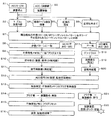
上述の如く構成された、実施形態の一例としての車載装置100における車載装置100の取り外し及び取り付け処理を、図3に示すフローチャート(ステップS1〜S22)に従って説明する。
例えば、車載装置100の修理等の保守作業を行なう場合に、保守作業者は車両1から車載装置100を取り外す。
The removal and attachment processing of the in-
For example, when performing maintenance work such as repair of the in-
車載装置100の取り外しを行なうに際して、ステップS1においてACCキーをOFFにして、車載装置100を停止させる。ただし、必ずしもACCキーをOFFにする必要はなく、ACCキーをONに維持し、車載装置100を稼動させたままであってもよい(ステップS2)。
保守作業者は、所定の規約に従って、コネクタ110から周辺装置200を接続するケーブル210の挿抜操作を行なう。例えば、ケーブル210をN回挿抜を繰り返したり(ステップS3)、接続されている複数のケーブル210を所定の順序で抜く(ステップS4)。もしくは、ケーブル210のN回の挿抜の繰り返しと、複数のケーブル210を所定の順序で抜く操作の所定の組合せを行なう(ステップS5)。このように、保守作業者は、車両1から車載装置100を取り外す前に、所定の規約に従ってコネクタ110からケーブル210の挿抜操作を行なう。
When removing the in-
The maintenance worker performs an insertion / extraction operation of the
一方、所定の規約操作を知らない不正な作業者は、これらのステップS3〜S5以外の操作でコネクタ110からケーブル210を取り外す(ステップS6)。
なお、この図3中においては、所定の規約がステップS3〜S5の3種類のいずれかの手法である例を示しているが、これに限定されるものではなく、これら以外の手法を所定の規約として用いてもよい。例えば、コネクタ110から周辺装置200と接続するケーブル210の挿抜にかかる時間(接続時間及び取り外し時間)の組合せを用いてもよい。
On the other hand, an unauthorized worker who does not know the predetermined rule operation removes the
FIG. 3 shows an example in which the predetermined rule is one of the three methods of steps S3 to S5. However, the present invention is not limited to this, and other methods may be used. It may be used as a convention. For example, a combination of time (connection time and removal time) required for insertion / extraction of the
ステップS7において、デコード部104は、周辺装置200経由でコネクタ110を介して入力された常時12VのON/OFFシーケンシャルパターンをデコードする。判断部105は、このデコード結果と、第2レジスタ107に格納されているシーケンシャルパターン(合格パターン)とを比較する。
デコード結果が合格パターンに一致した場合には(ステップS8)、制御回路部103はLED109を正常点灯・消灯させ、又、ステップS9において、不揮発性メモリ108に「一致」を示す判断フラグ“1”を設定する。
In step S <b> 7, the
When the decoding result matches the acceptable pattern (step S8), the control circuit unit 103 normally turns on / off the
その後、ステップS10において、保守作業者は、車載装置100への常時12V給電を切断して、車両1から車載装置100を撤去する。保守作業者は、車載装置100に対して部品の修理や交換等の保守作業を行なった後、ステップS11において、正常に動作する車載装置100を車両1に取り付け、常時12Vの給電(再給電)を行なう。
一方、ステップS7における比較の結果、デコード結果が合格パターンに不一致の場合には(ステップS17)、制御回路部103はLED109を異常点灯・消灯させ、又、ステップS18において、第1レジスタ106のレジスタ値(デコード結果)をリセットする。
Thereafter, in step S <b> 10, the maintenance worker always disconnects the 12V power supply to the in-
On the other hand, if the result of comparison in step S7 is that the decoded result does not match the accepted pattern (step S17), the control circuit unit 103 causes the
その後、ステップS19において、不正な作業者は、車載装置100への常時12V給電を切断して、車両1から車載装置100を撤去(盗難撤去)する。又、不正な作業者は、車両1から取り外した車載装置100を他の車両1′(図1参照)等に取り付け、常時12Vの給電(再給電)を行なう(ステップS20)。
ステップS12において、車載装置100が取り付けられた車両1,1′にACC電源がONされ、車載装置100が起動処理を開始する。
Thereafter, in step S <b> 19, the unauthorized worker disconnects the 12 V power supply to the in-
In step S12, the ACC power supply is turned on to the
ステップS13において、解除判定部111が、不揮発性メモリ108に判断フラグ“1”が設定されているか否かを確認する。
ここで、解除判定部111が、不揮発性メモリ108に判断フラグ“1”が設定されていると判断した場合には(ステップS14)、データ保護制御部102による機密情報保護動作を解除させる。すなわち、データ保護制御部102による記憶装置130の機密情報の削除等は行なわず、機密情報を読み出し可能な状態にする。
In step S <b> 13, the release determination unit 111 confirms whether or not the determination flag “1” is set in the
Here, when the cancellation determination unit 111 determines that the determination flag “1” is set in the nonvolatile memory 108 (step S <b> 14), the confidential information protection operation by the data
また、ステップS15において、判断部105(制御回路部103)は、不揮発性メモリ108の判断フラグをリセットする。その後、ステップS16において、車載装置100の起動処理が完了し、使用可能な状態となる。
一方、ステップS13の確認の結果、解除判定部111が、不揮発性メモリ108に判断フラグ“1”が設定されていないと判断した場合には(ステップS21)、ステップS22において、データ保護制御部102が、機密情報保護動作を実行し、記憶装置130の機密情報を読み出し不可の状態にする。
In step S15, the determination unit 105 (control circuit unit 103) resets the determination flag of the
On the other hand, when the release determination unit 111 determines that the determination flag “1” is not set in the
このように、実施形態の一例としての車載装置100によれば、所定の規約に従った操作を行なわずに車載装置100の電源を切断すると、不揮発性メモリ108に判断フラグ“1”が格納されない。これにより、次回起動時に、解除判定部111が不揮発性メモリ108から判断フラグ“1”を読み出すことができず、その起動プロセスにおいて、データ保護制御部102が記憶装置130の機密情報の読み出しを抑止する。
As described above, according to the in-
所定の規約に従った操作を行なわずに車載装置100の取り外しを行なった場合には、記憶装置130から機密情報が読み出し不可の状態となるので、機密情報の漏洩を効率的に防止することができる。
また、上述した所定の規約に従った操作が、コネクタ110を介した周辺装置200とのケーブル210の取り外し操作及び取り付け操作(挿抜操作)の組合せである。これにより、例えば、パスワード入力やダイヤル操作,鍵操作,ICカードを用いた照合等のデータ保護処理解除に一般的な機器を用いた操作を行なう必要がなく、製造コストを低減できる。又、不正な作業者にデータ保護処理解除を意識させることがなく、セキュリティレベルを向上させることができる。
If the in-
Further, the operation in accordance with the above-mentioned predetermined rule is a combination of the operation of removing and attaching the
また、コネクタ110からケーブル210を取り外す作業は、一般に、車載装置100の保守作業を行なうために必然に行なわれる作業である。すなわち、正当な保守作業者は、コネクタ110からケーブル210を取り外すという必然作業を行なう一環として、データ保護に関する所定の規約に従った操作を行なうことができ利便性が高い。
一方、不正に車載装置100を取り外す不正作業者が、車載装置100を持ち去る際に必然作業(12V電源線やケーブル210の無造作な取り外し作業)を行なうことで、不揮発性メモリ108に判断フラグ“1”が格納されない。すなわち、不正作業者による必然作業が不正行為の烙印付けとなる。
Further, the operation of removing the
On the other hand, a fraudulent worker who removes the in-
そして、不正作業者が本車載装置100を持ち去った後、起動させる作業(電源線接続及び起動信号(ACC)ON)を行なうことで、その起動プロセスにおいて、解除判定部111が不揮発性メモリ108から判断フラグ“1”を読み出すことができず、データ保護制御部102が記憶装置130の機密情報の読み出しを抑止する。これにより、盗難後の最初の常時12V電源接続及び最初のACC起動により、自動的に機密情報の読み出しが阻止され、即時のデータ保護を実現できる。
Then, after the unauthorized worker takes away the in-
そして、開示の技術は上述した実施形態に限定されるものではなく、本実施形態の趣旨を逸脱しない範囲で種々変形して実施することができる。本実施形態の各構成及び各処理は、必要に応じて取捨選択することができ、あるいは適宜組み合わせてもよい。
例えば、上述した実施形態においては、デコード部104,判断部105,第1レジスタ106及び第2レジスタ107としての機能が制御回路部103に搭載されているが、これに限定されるものではない。例えば、制御回路部103に代えて、常時12Vの供給電力で動作可能なCPU(Central Processing Unit)やメモリを備え、CPUがメモリから読み出した制御プログラムを実行することで、同等の機能を実現してもよい。この場合、第1レジスタ106及び第2レジスタ107としての機能をメモリによって実現することができる。又、データ保護制御部102及び解除判定部111としての機能もこのCPUにより実現してもよい。
The disclosed technology is not limited to the above-described embodiment, and various modifications can be made without departing from the spirit of the present embodiment. Each structure and each process of this embodiment can be selected as needed, or may be combined suitably.
For example, in the above-described embodiment, functions as the
すなわち、このCPUが、制御プログラムを実行することにより、上述したデータ保護制御部102,解除判定部111,デコード部104及び判断部105として機能する。
なお、これらのデータ保護制御部102,解除判定部111,デコード部104及び判断部105としての機能を実現するためのプログラム(制御プログラム)は、例えばフレキシブルディスク,CD(CD−ROM,CD−R,CD−RW等),DVD(DVD−ROM,DVD−RAM,DVD−R,DVD+R,DVD−RW,DVD+RW,HD DVD等),ブルーレイディスク,磁気ディスク,光ディスク,光磁気ディスク等の、コンピュータ読取可能な記録媒体に記録された形態で提供される。そして、コンピュータはその記録媒体からプログラムを読み取って内部記憶装置または外部記憶装置に転送し格納して用いる。又、そのプログラムを、例えば磁気ディスク,光ディスク,光磁気ディスク等の記憶装置(記録媒体)に記録しておき、その記憶装置から通信経路を介してコンピュータに提供するようにしてもよい。
That is, the CPU functions as the data
Note that programs (control programs) for realizing the functions as the data
データ保護制御部102,解除判定部111,デコード部104及び判断部105としての機能を実現する際には、内部記憶装置(本実施形態ではメモリ)に格納されたプログラムがコンピュータのマイクロプロセッサ(本実施形態ではCPU)によって実行される。このとき、記録媒体に記録されたプログラムをコンピュータが読み取って実行するようにしてもよい。
When realizing the functions as the data
なお、本実施形態において、コンピュータとは、ハードウェアとオペレーティングシステムとを含む概念であり、オペレーティングシステムの制御の下で動作するハードウェアを意味している。又、オペレーティングシステムが不要でアプリケーションプログラム単独でハードウェアを動作させるような場合には、そのハードウェア自体がコンピュータに相当する。ハードウェアは、少なくとも、CPU等のマイクロプロセッサと、記録媒体に記録されたコンピュータプログラムを読み取るための手段とをそなえており、本実施形態においては、車載装置100がコンピュータとしての機能を有しているのである。
In the present embodiment, the computer is a concept including hardware and an operating system, and means hardware that operates under the control of the operating system. Further, when an operating system is unnecessary and hardware is operated by an application program alone, the hardware itself corresponds to a computer. The hardware includes at least a microprocessor such as a CPU and means for reading a computer program recorded on a recording medium. In the present embodiment, the in-
また、上述した実施形態においては、2つの周辺装置200a,200bが車載装置100に接続される例を示しているが、これに限定されるものではなく、1つもしくは3つ以上の周辺装置200を車載装置100に接続してもよい。
さらに、上述した実施形態においては、車両1に搭載される車載装置100について示したが、これに限定されるものではなく、種々変形して実施することができる。例えば、車載装置に代えて、ラック等にマウントされ周辺機器(電子装置)と接続されるサーバ装置(情報処理装置)等であってもよい。この場合、例えば、LAN(Local Area Network)ケーブルやUSB(Universal Serial Bus)ケーブル等の各種ケーブルの挿抜操作を所定の規約に従って行なうことで、コネクタ110へのケーブル210の挿抜と同様に実現できる。
In the above-described embodiment, an example is shown in which two
Furthermore, in the above-described embodiment, the on-
上述した開示により本実施形態を当業者によって実施・製造することが可能である。 According to the above-described disclosure, this embodiment can be implemented and manufactured by those skilled in the art.
1 車両(移動体)
100 車載装置(情報処理装置)
101 給電制御部
102 データ保護制御部(禁止制御部)
103 制御回路部
104 デコード部(監視部)
105 判断部(格納処理部)
106 第1レジスタ
107 第2レジスタ
108 不揮発性メモリ(不揮発性記憶部)
109 LED
110,110a,110b コネクタ(接続部)
111 解除判定部(抑止部)
120 制御装置
130 記憶装置
200,200a,200b 周辺装置(電子装置)
210a,210b ケーブル
300 関連機器
1 Vehicle (moving body)
100 In-vehicle device (information processing device)
101 Power
103
105 Judgment unit (storage processing unit)
106
109 LED
110, 110a, 110b Connector (connection part)
111 Cancellation determination unit (suppression unit)
120
210a, 210b Cable 300 related equipment
Claims (15)
当該情報処理装置の起動過程において、前記情報の読み出しを禁止する禁止制御部と、
1以上の電子装置と接続可能な接続部と、
前記接続部を介した前記電子装置の着脱操作を監視する監視部と、
前記監視部が監視した前記着脱操作が予め規定された基準操作パターンと一致した場合に、規定操作が行なわれたことを示す識別情報を不揮発性記憶部に格納する格納処理部と、
当該情報処理装置の起動過程において、前記不揮発性記憶部から前記識別情報を読み出した場合に、前記禁止制御部による前記情報の読み出し禁止を抑止する抑止部と
を備えることを特徴とする、情報処理装置。 An information processing apparatus in which information is stored,
In the startup process of the information processing apparatus, a prohibition control unit that prohibits reading of the information;
A connection portion connectable to one or more electronic devices;
A monitoring unit for monitoring an attaching / detaching operation of the electronic device via the connecting unit;
A storage processing unit that stores identification information indicating that a prescribed operation has been performed in a nonvolatile storage unit when the attachment / detachment operation monitored by the monitoring unit matches a predefined reference operation pattern ;
An information processing system comprising: a suppression unit that suppresses prohibition of reading of the information by the prohibition control unit when the identification information is read from the nonvolatile storage unit in a startup process of the information processing apparatus. apparatus.
接続部を介した電子装置の着脱操作を監視し、
監視した前記着脱操作が予め規定された基準操作パターンと一致した場合に、規定操作が行なわれたことを示す識別情報を不揮発性記憶部に格納し、
当該情報処理装置の起動過程において、前記不揮発性記憶部から前記識別情報を読み出せない場合には、前記情報の読み出しを禁止し、
当該情報処理装置の起動過程において、前記不揮発性記憶部から前記識別情報を読み出した場合には、前記情報の読み出しを許可する
ことを特徴とする、制御方法。 A method for controlling an information processing apparatus in which information is stored,
Monitors the attachment / detachment operation of the electronic device via the connection part,
When the detachable operation monitored matches a predefined reference operation pattern, the identification information indicating that the specified operation has been performed is stored in the nonvolatile storage unit,
When the identification information cannot be read from the nonvolatile storage unit in the startup process of the information processing apparatus, reading of the information is prohibited,
A control method characterized by permitting reading of the information when the identification information is read from the non-volatile storage unit in the startup process of the information processing apparatus.
接続部を介した電子装置の着脱操作を監視し、
監視した前記着脱操作が予め規定された基準操作パターンと一致した場合に、規定操作が行なわれたことを示す識別情報を不揮発性記憶部に格納させ、
当該コンピュータの起動過程において、前記不揮発性記憶部から、予め設定された条件に従った操作が行なわれた場合に規定操作が行なわれたことを示す前記識別情報を読み出せない場合には、前記情報の読み出しを禁止し、
当該コンピュータの起動過程において、前記不揮発性記憶部から前記識別情報を読み出した場合には、前記情報の読み出しを許可する処理を前記コンピュータに実行させることを特徴とする、制御プログラム。 In the computer where the information is stored,
Monitors the attachment / detachment operation of the electronic device via the connection part,
When the monitored attachment / detachment operation matches a predefined reference operation pattern, identification information indicating that the prescribed operation has been performed is stored in the nonvolatile storage unit,
In starting the process of the computer, from said nonvolatile storage unit, if the prescribed operation when an operation in accordance with a preset condition has been performed can not read the identification information indicating that it has been made, the Prohibit reading information,
In starting the process of the computer, when said nonvolatile memory unit and reads the identification information is characterized in that to execute a process to allow the reading of the information to the computer, the control program.
Priority Applications (1)
| Application Number | Priority Date | Filing Date | Title |
|---|---|---|---|
| JP2013106092A JP6089956B2 (en) | 2013-05-20 | 2013-05-20 | Information processing apparatus, control method, and control program |
Applications Claiming Priority (1)
| Application Number | Priority Date | Filing Date | Title |
|---|---|---|---|
| JP2013106092A JP6089956B2 (en) | 2013-05-20 | 2013-05-20 | Information processing apparatus, control method, and control program |
Publications (2)
| Publication Number | Publication Date |
|---|---|
| JP2014228933A JP2014228933A (en) | 2014-12-08 |
| JP6089956B2 true JP6089956B2 (en) | 2017-03-08 |
Family
ID=52128754
Family Applications (1)
| Application Number | Title | Priority Date | Filing Date |
|---|---|---|---|
| JP2013106092A Expired - Fee Related JP6089956B2 (en) | 2013-05-20 | 2013-05-20 | Information processing apparatus, control method, and control program |
Country Status (1)
| Country | Link |
|---|---|
| JP (1) | JP6089956B2 (en) |
Families Citing this family (1)
| Publication number | Priority date | Publication date | Assignee | Title |
|---|---|---|---|---|
| CN105138933B (en) * | 2015-09-25 | 2018-07-06 | 联想(北京)有限公司 | A kind of electronic equipment and information processing method |
Family Cites Families (6)
| Publication number | Priority date | Publication date | Assignee | Title |
|---|---|---|---|---|
| WO2006046304A1 (en) * | 2004-10-29 | 2006-05-04 | Fujitsu Limited | Terminal security protective device, terminal security protective method, and terminal security protective program |
| JP2009037380A (en) * | 2007-08-01 | 2009-02-19 | Seiko Epson Corp | Electronic equipment and method for starting electronic equipment |
| JP2010026662A (en) * | 2008-07-16 | 2010-02-04 | Sky Co Ltd | Information leakage prevention system |
| JP5250843B2 (en) * | 2009-05-15 | 2013-07-31 | コニカミノルタ株式会社 | Portable information storage terminal and information management system using portable information storage terminal |
| JP2011028647A (en) * | 2009-07-28 | 2011-02-10 | Le Tekku:Kk | Personal digital assistant |
| JP5639501B2 (en) * | 2011-02-22 | 2014-12-10 | Sky株式会社 | Theft state determination system and theft state determination program |
-
2013
- 2013-05-20 JP JP2013106092A patent/JP6089956B2/en not_active Expired - Fee Related
Also Published As
| Publication number | Publication date |
|---|---|
| JP2014228933A (en) | 2014-12-08 |
Similar Documents
| Publication | Publication Date | Title |
|---|---|---|
| JP4769861B2 (en) | Electronic device, management method, and management program | |
| JP4864081B2 (en) | Electronic apparatus and information processing apparatus | |
| TW408268B (en) | Remote security technology | |
| JP2006524861A (en) | Dead on demand disk technology | |
| JP5673417B2 (en) | Data recovery method, data recovery device, and data recovery program | |
| JP4756070B2 (en) | Information processing apparatus, management method, and management program | |
| CN106716333B (en) | Method for completing secure erase operation | |
| US8844060B2 (en) | Method and system for USB with an integrated crypto ignition key | |
| JP5652297B2 (en) | Information terminal, information leakage prevention method and information leakage prevention program | |
| WO2013178117A1 (en) | Mobile terminal detection method and mobile terminal | |
| CN106919859B (en) | Basic input output system protection method and device | |
| CN103995723A (en) | IVI system firmware updating method and device based on mobile storage equipment | |
| JP6089956B2 (en) | Information processing apparatus, control method, and control program | |
| CN103294971A (en) | Method for realizing burglary prevention and data protection of hard disk | |
| JP5051291B2 (en) | Portable storage device | |
| WO2008078931A1 (en) | Apparatus and method for managing rights object | |
| JP2006146358A (en) | Usb peripheral equipment control system and usb peripheral equipment control method | |
| US8576679B2 (en) | Apparatus and method for using content on an optical disc having plural partial areas for recording control information indicating that the use of the content is not permitted | |
| EP2450817A1 (en) | Electronic component with time-limited use | |
| US10380385B1 (en) | Visual security device | |
| JP2010049612A (en) | Accessory authenticating system, accessory authentication method, and main device and the accessory | |
| JP5295156B2 (en) | Information processing apparatus and software unauthorized use prevention method | |
| WO2016186109A1 (en) | Storage device, access prohibition method, and program | |
| JP4801729B2 (en) | Electronic device and program | |
| JP2008181467A (en) | Device for preventing outflow of information for portable terminal |
Legal Events
| Date | Code | Title | Description |
|---|---|---|---|
| A621 | Written request for application examination |
Free format text: JAPANESE INTERMEDIATE CODE: A621 Effective date: 20160226 |
|
| A131 | Notification of reasons for refusal |
Free format text: JAPANESE INTERMEDIATE CODE: A131 Effective date: 20161101 |
|
| A521 | Written amendment |
Free format text: JAPANESE INTERMEDIATE CODE: A523 Effective date: 20161222 |
|
| TRDD | Decision of grant or rejection written | ||
| A01 | Written decision to grant a patent or to grant a registration (utility model) |
Free format text: JAPANESE INTERMEDIATE CODE: A01 Effective date: 20170110 |
|
| A61 | First payment of annual fees (during grant procedure) |
Free format text: JAPANESE INTERMEDIATE CODE: A61 Effective date: 20170123 |
|
| R150 | Certificate of patent or registration of utility model |
Ref document number: 6089956 Country of ref document: JP Free format text: JAPANESE INTERMEDIATE CODE: R150 |
|
| LAPS | Cancellation because of no payment of annual fees |