JP6087358B2 - Detecting the processing state of objects using RF radiation - Google Patents
Detecting the processing state of objects using RF radiation Download PDFInfo
- Publication number
- JP6087358B2 JP6087358B2 JP2014528578A JP2014528578A JP6087358B2 JP 6087358 B2 JP6087358 B2 JP 6087358B2 JP 2014528578 A JP2014528578 A JP 2014528578A JP 2014528578 A JP2014528578 A JP 2014528578A JP 6087358 B2 JP6087358 B2 JP 6087358B2
- Authority
- JP
- Japan
- Prior art keywords
- energy
- feedback
- processing
- controller
- computed
- Prior art date
- Legal status (The legal status is an assumption and is not a legal conclusion. Google has not performed a legal analysis and makes no representation as to the accuracy of the status listed.)
- Active
Links
- 238000012545 processing Methods 0.000 title claims description 286
- 230000005855 radiation Effects 0.000 title description 9
- 230000005284 excitation Effects 0.000 claims description 156
- 238000000034 method Methods 0.000 claims description 124
- 238000010411 cooking Methods 0.000 claims description 57
- 230000008569 process Effects 0.000 claims description 57
- 238000010438 heat treatment Methods 0.000 claims description 50
- 230000002596 correlated effect Effects 0.000 claims description 32
- 235000013305 food Nutrition 0.000 claims description 25
- 239000000126 substance Substances 0.000 claims description 20
- 230000004044 response Effects 0.000 claims description 13
- 230000001276 controlling effect Effects 0.000 claims description 12
- 238000012544 monitoring process Methods 0.000 claims description 11
- 238000010521 absorption reaction Methods 0.000 claims description 7
- 238000001514 detection method Methods 0.000 claims description 5
- 230000000704 physical effect Effects 0.000 claims description 4
- 235000013550 pizza Nutrition 0.000 description 26
- 230000006870 function Effects 0.000 description 18
- 230000008859 change Effects 0.000 description 15
- 239000000463 material Substances 0.000 description 15
- 238000002474 experimental method Methods 0.000 description 14
- 238000010257 thawing Methods 0.000 description 11
- 239000000203 mixture Substances 0.000 description 9
- 238000005192 partition Methods 0.000 description 9
- 238000010408 sweeping Methods 0.000 description 9
- 239000007788 liquid Substances 0.000 description 8
- 238000013515 script Methods 0.000 description 8
- 239000007787 solid Substances 0.000 description 7
- 238000012360 testing method Methods 0.000 description 6
- 240000004808 Saccharomyces cerevisiae Species 0.000 description 5
- 239000007789 gas Substances 0.000 description 5
- 229920000642 polymer Polymers 0.000 description 5
- 238000006243 chemical reaction Methods 0.000 description 4
- 230000000875 corresponding effect Effects 0.000 description 4
- 230000003247 decreasing effect Effects 0.000 description 4
- 238000004519 manufacturing process Methods 0.000 description 4
- 235000013372 meat Nutrition 0.000 description 4
- 230000007246 mechanism Effects 0.000 description 4
- 235000009499 Vanilla fragrans Nutrition 0.000 description 3
- 244000263375 Vanilla tahitensis Species 0.000 description 3
- 235000012036 Vanilla tahitensis Nutrition 0.000 description 3
- 229910045601 alloy Inorganic materials 0.000 description 3
- 239000000956 alloy Substances 0.000 description 3
- 230000005540 biological transmission Effects 0.000 description 3
- 238000004891 communication Methods 0.000 description 3
- 239000002131 composite material Substances 0.000 description 3
- 238000013500 data storage Methods 0.000 description 3
- 238000001035 drying Methods 0.000 description 3
- 230000000694 effects Effects 0.000 description 3
- 235000012396 frozen pizza Nutrition 0.000 description 3
- 238000005259 measurement Methods 0.000 description 3
- 239000000843 powder Substances 0.000 description 3
- 238000001228 spectrum Methods 0.000 description 3
- 230000000007 visual effect Effects 0.000 description 3
- 229910001018 Cast iron Inorganic materials 0.000 description 2
- 241000287828 Gallus gallus Species 0.000 description 2
- 230000008901 benefit Effects 0.000 description 2
- 235000021028 berry Nutrition 0.000 description 2
- 235000008429 bread Nutrition 0.000 description 2
- 238000010924 continuous production Methods 0.000 description 2
- 230000001934 delay Effects 0.000 description 2
- 239000003989 dielectric material Substances 0.000 description 2
- 235000013601 eggs Nutrition 0.000 description 2
- 239000012530 fluid Substances 0.000 description 2
- 239000000446 fuel Substances 0.000 description 2
- 239000011521 glass Substances 0.000 description 2
- 230000003071 parasitic effect Effects 0.000 description 2
- 230000036961 partial effect Effects 0.000 description 2
- 230000001902 propagating effect Effects 0.000 description 2
- 239000004065 semiconductor Substances 0.000 description 2
- 229910001220 stainless steel Inorganic materials 0.000 description 2
- 230000036962 time dependent Effects 0.000 description 2
- 239000011800 void material Substances 0.000 description 2
- RZVAJINKPMORJF-UHFFFAOYSA-N Acetaminophen Chemical compound CC(=O)NC1=CC=C(O)C=C1 RZVAJINKPMORJF-UHFFFAOYSA-N 0.000 description 1
- 229910000838 Al alloy Inorganic materials 0.000 description 1
- RYGMFSIKBFXOCR-UHFFFAOYSA-N Copper Chemical compound [Cu] RYGMFSIKBFXOCR-UHFFFAOYSA-N 0.000 description 1
- 239000004809 Teflon Substances 0.000 description 1
- 229920006362 Teflon® Polymers 0.000 description 1
- 239000011358 absorbing material Substances 0.000 description 1
- 230000004075 alteration Effects 0.000 description 1
- 229910052782 aluminium Inorganic materials 0.000 description 1
- XAGFODPZIPBFFR-UHFFFAOYSA-N aluminium Chemical compound [Al] XAGFODPZIPBFFR-UHFFFAOYSA-N 0.000 description 1
- 235000013549 apple pie Nutrition 0.000 description 1
- 235000013405 beer Nutrition 0.000 description 1
- 230000006399 behavior Effects 0.000 description 1
- 230000000903 blocking effect Effects 0.000 description 1
- 238000009529 body temperature measurement Methods 0.000 description 1
- 230000003197 catalytic effect Effects 0.000 description 1
- 239000000919 ceramic Substances 0.000 description 1
- 229910010293 ceramic material Inorganic materials 0.000 description 1
- 235000013351 cheese Nutrition 0.000 description 1
- 239000011248 coating agent Substances 0.000 description 1
- 238000000576 coating method Methods 0.000 description 1
- 238000002485 combustion reaction Methods 0.000 description 1
- 238000010276 construction Methods 0.000 description 1
- 229910052802 copper Inorganic materials 0.000 description 1
- 239000010949 copper Substances 0.000 description 1
- 238000005260 corrosion Methods 0.000 description 1
- 230000007797 corrosion Effects 0.000 description 1
- 230000007423 decrease Effects 0.000 description 1
- 230000001419 dependent effect Effects 0.000 description 1
- 238000010586 diagram Methods 0.000 description 1
- 235000021186 dishes Nutrition 0.000 description 1
- 238000000855 fermentation Methods 0.000 description 1
- 230000004151 fermentation Effects 0.000 description 1
- 239000010794 food waste Substances 0.000 description 1
- 150000004677 hydrates Chemical class 0.000 description 1
- 238000007689 inspection Methods 0.000 description 1
- 230000003993 interaction Effects 0.000 description 1
- 229910052751 metal Inorganic materials 0.000 description 1
- 239000002184 metal Substances 0.000 description 1
- 239000007769 metal material Substances 0.000 description 1
- 150000002739 metals Chemical class 0.000 description 1
- 239000008267 milk Substances 0.000 description 1
- 235000013336 milk Nutrition 0.000 description 1
- 210000004080 milk Anatomy 0.000 description 1
- 238000012986 modification Methods 0.000 description 1
- 230000004048 modification Effects 0.000 description 1
- 238000012806 monitoring device Methods 0.000 description 1
- 230000003287 optical effect Effects 0.000 description 1
- 239000013307 optical fiber Substances 0.000 description 1
- 210000000056 organ Anatomy 0.000 description 1
- 239000002245 particle Substances 0.000 description 1
- 235000014594 pastries Nutrition 0.000 description 1
- 238000006116 polymerization reaction Methods 0.000 description 1
- 229920001296 polysiloxane Polymers 0.000 description 1
- 102000004169 proteins and genes Human genes 0.000 description 1
- 108090000623 proteins and genes Proteins 0.000 description 1
- 239000005297 pyrex Substances 0.000 description 1
- 239000000376 reactant Substances 0.000 description 1
- 239000011541 reaction mixture Substances 0.000 description 1
- 238000005245 sintering Methods 0.000 description 1
- 230000003595 spectral effect Effects 0.000 description 1
- 239000010935 stainless steel Substances 0.000 description 1
- 230000001360 synchronised effect Effects 0.000 description 1
- 239000005393 tempered soda-lime glass Substances 0.000 description 1
- 238000012546 transfer Methods 0.000 description 1
- 230000001960 triggered effect Effects 0.000 description 1
- 235000013311 vegetables Nutrition 0.000 description 1
- 238000011179 visual inspection Methods 0.000 description 1
- XLYOFNOQVPJJNP-UHFFFAOYSA-N water Chemical compound O XLYOFNOQVPJJNP-UHFFFAOYSA-N 0.000 description 1
Images


Classifications
-
- G—PHYSICS
- G01—MEASURING; TESTING
- G01N—INVESTIGATING OR ANALYSING MATERIALS BY DETERMINING THEIR CHEMICAL OR PHYSICAL PROPERTIES
- G01N22/00—Investigating or analysing materials by the use of microwaves or radio waves, i.e. electromagnetic waves with a wavelength of one millimetre or more
-
- H—ELECTRICITY
- H05—ELECTRIC TECHNIQUES NOT OTHERWISE PROVIDED FOR
- H05B—ELECTRIC HEATING; ELECTRIC LIGHT SOURCES NOT OTHERWISE PROVIDED FOR; CIRCUIT ARRANGEMENTS FOR ELECTRIC LIGHT SOURCES, IN GENERAL
- H05B6/00—Heating by electric, magnetic or electromagnetic fields
- H05B6/64—Heating using microwaves
- H05B6/6435—Aspects relating to the user interface of the microwave heating apparatus
- H05B6/6441—Aspects relating to the user interface of the microwave heating apparatus allowing the input of coded operation instructions, e.g. bar code reader
-
- G—PHYSICS
- G01—MEASURING; TESTING
- G01N—INVESTIGATING OR ANALYSING MATERIALS BY DETERMINING THEIR CHEMICAL OR PHYSICAL PROPERTIES
- G01N27/00—Investigating or analysing materials by the use of electric, electrochemical, or magnetic means
-
- G—PHYSICS
- G01—MEASURING; TESTING
- G01N—INVESTIGATING OR ANALYSING MATERIALS BY DETERMINING THEIR CHEMICAL OR PHYSICAL PROPERTIES
- G01N27/00—Investigating or analysing materials by the use of electric, electrochemical, or magnetic means
- G01N27/02—Investigating or analysing materials by the use of electric, electrochemical, or magnetic means by investigating impedance
- G01N27/04—Investigating or analysing materials by the use of electric, electrochemical, or magnetic means by investigating impedance by investigating resistance
-
- G—PHYSICS
- G06—COMPUTING; CALCULATING OR COUNTING
- G06F—ELECTRIC DIGITAL DATA PROCESSING
- G06F15/00—Digital computers in general; Data processing equipment in general
-
- H—ELECTRICITY
- H05—ELECTRIC TECHNIQUES NOT OTHERWISE PROVIDED FOR
- H05B—ELECTRIC HEATING; ELECTRIC LIGHT SOURCES NOT OTHERWISE PROVIDED FOR; CIRCUIT ARRANGEMENTS FOR ELECTRIC LIGHT SOURCES, IN GENERAL
- H05B6/00—Heating by electric, magnetic or electromagnetic fields
- H05B6/64—Heating using microwaves
- H05B6/6447—Method of operation or details of the microwave heating apparatus related to the use of detectors or sensors
- H05B6/6467—Method of operation or details of the microwave heating apparatus related to the use of detectors or sensors using detectors with R.F. transmitters
-
- H—ELECTRICITY
- H05—ELECTRIC TECHNIQUES NOT OTHERWISE PROVIDED FOR
- H05B—ELECTRIC HEATING; ELECTRIC LIGHT SOURCES NOT OTHERWISE PROVIDED FOR; CIRCUIT ARRANGEMENTS FOR ELECTRIC LIGHT SOURCES, IN GENERAL
- H05B6/00—Heating by electric, magnetic or electromagnetic fields
- H05B6/64—Heating using microwaves
- H05B6/647—Aspects related to microwave heating combined with other heating techniques
- H05B6/6473—Aspects related to microwave heating combined with other heating techniques combined with convection heating
-
- H—ELECTRICITY
- H05—ELECTRIC TECHNIQUES NOT OTHERWISE PROVIDED FOR
- H05B—ELECTRIC HEATING; ELECTRIC LIGHT SOURCES NOT OTHERWISE PROVIDED FOR; CIRCUIT ARRANGEMENTS FOR ELECTRIC LIGHT SOURCES, IN GENERAL
- H05B6/00—Heating by electric, magnetic or electromagnetic fields
- H05B6/64—Heating using microwaves
- H05B6/647—Aspects related to microwave heating combined with other heating techniques
- H05B6/6482—Aspects related to microwave heating combined with other heating techniques combined with radiant heating, e.g. infrared heating
- H05B6/6485—Aspects related to microwave heating combined with other heating techniques combined with radiant heating, e.g. infrared heating further combined with convection heating
-
- H—ELECTRICITY
- H05—ELECTRIC TECHNIQUES NOT OTHERWISE PROVIDED FOR
- H05B—ELECTRIC HEATING; ELECTRIC LIGHT SOURCES NOT OTHERWISE PROVIDED FOR; CIRCUIT ARRANGEMENTS FOR ELECTRIC LIGHT SOURCES, IN GENERAL
- H05B6/00—Heating by electric, magnetic or electromagnetic fields
- H05B6/64—Heating using microwaves
- H05B6/66—Circuits
- H05B6/68—Circuits for monitoring or control
- H05B6/688—Circuits for monitoring or control for thawing
-
- H—ELECTRICITY
- H05—ELECTRIC TECHNIQUES NOT OTHERWISE PROVIDED FOR
- H05B—ELECTRIC HEATING; ELECTRIC LIGHT SOURCES NOT OTHERWISE PROVIDED FOR; CIRCUIT ARRANGEMENTS FOR ELECTRIC LIGHT SOURCES, IN GENERAL
- H05B6/00—Heating by electric, magnetic or electromagnetic fields
- H05B6/64—Heating using microwaves
- H05B6/70—Feed lines
- H05B6/705—Feed lines using microwave tuning
-
- Y—GENERAL TAGGING OF NEW TECHNOLOGICAL DEVELOPMENTS; GENERAL TAGGING OF CROSS-SECTIONAL TECHNOLOGIES SPANNING OVER SEVERAL SECTIONS OF THE IPC; TECHNICAL SUBJECTS COVERED BY FORMER USPC CROSS-REFERENCE ART COLLECTIONS [XRACs] AND DIGESTS
- Y02—TECHNOLOGIES OR APPLICATIONS FOR MITIGATION OR ADAPTATION AGAINST CLIMATE CHANGE
- Y02B—CLIMATE CHANGE MITIGATION TECHNOLOGIES RELATED TO BUILDINGS, e.g. HOUSING, HOUSE APPLIANCES OR RELATED END-USER APPLICATIONS
- Y02B40/00—Technologies aiming at improving the efficiency of home appliances, e.g. induction cooking or efficient technologies for refrigerators, freezers or dish washers
Landscapes
- Physics & Mathematics (AREA)
- Electromagnetism (AREA)
- Chemical & Material Sciences (AREA)
- Engineering & Computer Science (AREA)
- General Physics & Mathematics (AREA)
- Life Sciences & Earth Sciences (AREA)
- Analytical Chemistry (AREA)
- Biochemistry (AREA)
- General Health & Medical Sciences (AREA)
- Immunology (AREA)
- Pathology (AREA)
- Health & Medical Sciences (AREA)
- Chemical Kinetics & Catalysis (AREA)
- Electrochemistry (AREA)
- Theoretical Computer Science (AREA)
- Human Computer Interaction (AREA)
- General Engineering & Computer Science (AREA)
- Computer Hardware Design (AREA)
- Control Of High-Frequency Heating Circuits (AREA)
- Electric Ovens (AREA)
- Drying Of Semiconductors (AREA)
- Testing Or Measuring Of Semiconductors Or The Like (AREA)
Description
この出願は、2011年8月31日に出願された米国仮特許出願第61/529,361号明細書の優先権の利益を主張し、また、2012年3月19日に出願された米国仮特許出願第61/612,961号明細書の優先権の利益を主張し、両特許は、その全体が参照により本明細書に組み込まれる。 This application claims the benefit of priority from US Provisional Patent Application No. 61 / 529,361, filed on August 31, 2011, and is filed on March 19, 2012. Claiming the benefit of priority of patent application 61 / 612,961, both patents are hereby incorporated by reference in their entirety.
この出願は、電磁エネルギーを印加するためのデバイスおよび方法に関する。より具体的には、限定的にではないが、開示される実施形態は、無線周波数範囲で電磁エネルギーを印加して、処理中の対象物の処理状態を決定または検出するためのデバイスおよび方法に関し得る。 This application relates to devices and methods for applying electromagnetic energy. More specifically, but not exclusively, disclosed embodiments relate to devices and methods for applying electromagnetic energy in the radio frequency range to determine or detect the processing state of an object being processed. obtain.
電磁(EM)波は、エネルギーを対象物に供給するために様々な応用において使用されてきた。例えば、無線周波数(RF)放射の場合、マグネトロンを使用してRFエネルギーを供給することができ、通常、マグネトロンを単一の周波数に合わせて、その周波数でのみRFエネルギーを供給する。RFエネルギーを供給するために一般的に使用されるデバイスの一例は、電子レンジである。典型的な電子レンジは、単一の周波数2.45GHzでまたはその周辺でRFエネルギーを供給する。対象物の処理には他の装置も使用されてきた。例えば、従来のオーブンは、対象物の調理、加熱および乾燥に使用することができる。他の処理装置は、化学製品生産、製品製造、材料製作などの分野で使用することができる。これらの分野または装置の各々において、1つまたは複数のプロセスの進行度をモニタする必要性が存在し得る。 Electromagnetic (EM) waves have been used in various applications to deliver energy to objects. For example, in the case of radio frequency (RF) radiation, a magnetron can be used to supply the RF energy, and typically the magnetron is tuned to a single frequency and the RF energy is supplied only at that frequency. One example of a device commonly used to supply RF energy is a microwave oven. A typical microwave oven supplies RF energy at or around a single frequency of 2.45 GHz. Other devices have also been used to process objects. For example, a conventional oven can be used for cooking, heating and drying objects. Other processing equipment can be used in fields such as chemical product production, product manufacturing, and material production. In each of these areas or devices, there may be a need to monitor the progress of one or more processes.
本発明のいくつかの例示的な態様は、RFエネルギーを印加して、処理すべき(例えば、加熱すべき)エネルギー印加ゾーンに配置された対象物の1つまたは複数の処理状態を検出および検知するための方法および装置を対象とし得る。対象物は、例えば、対流加熱、赤外線(IR)放射(加熱)など、様々なタイプのエネルギーを印加することによって処理することができる。対流および/またはIR加熱の印加に加えて、IRおよび/もしくは対流加熱と同時に、または、IRおよび/もしくは対流加熱の代わりに、RFエネルギーを印加して対象物を処理することもできる。任意選択で、RFエネルギーは、IRおよび/もしくは対流加熱の前、ならびに/または、IRおよび/もしくは対流加熱の後に印加することができる。処理の間に対象物に起こり得る変化は、対象物の処理状態と呼ぶことができる。対象物の処理状態のいくつかの例は、対象物の物理的特性(例えば、温度、圧力、流量、様相など)、対象物の化学的特性(例えば、pH、化学組成など)を含み得、対象物が食品の場合は、対象物の処理状態は、対象物の調理および/または仕上がり状態(例えば、解凍済み、発酵済み、完全にベーキング済み/調理済み)を含み得る。処理の間の対象物における変化は、RFエネルギー印加に対する対象物の誘電挙動および応答に影響を及ぼし得る。任意選択でRFエネルギー印加に応答して、エネルギー印加ゾーンから受信される1つまたは複数のRFフィードバックは、対象物の1つまたは複数の処理状態と相関させることができる。RFフィードバックは、対象物の1つまたは複数の処理状態を検出するため、対象物の処理の間、モニタすることができる。 Some exemplary aspects of the present invention apply RF energy to detect and sense one or more processing states of an object placed in an energy application zone to be processed (eg, heated). Methods and apparatus for doing so may be directed. The object can be treated by applying various types of energy, such as convection heating, infrared (IR) radiation (heating), and the like. In addition to applying convection and / or IR heating, RF energy can be applied to treat the object simultaneously with IR and / or convection heating or instead of IR and / or convection heating. Optionally, the RF energy can be applied before IR and / or convection heating and / or after IR and / or convection heating. Changes that can occur to an object during processing can be referred to as the processing state of the object. Some examples of the processing state of an object may include the physical properties of the object (eg, temperature, pressure, flow rate, aspect, etc.), the chemical properties of the object (eg, pH, chemical composition, etc.) If the object is a food product, the processing state of the object may include the cooked and / or finished state of the object (eg, thawed, fermented, fully baked / cooked). Changes in the object during processing can affect the dielectric behavior and response of the object to RF energy application. Optionally, in response to the RF energy application, the one or more RF feedbacks received from the energy application zone can be correlated with one or more processing states of the object. RF feedback can be monitored during processing of an object to detect one or more processing states of the object.
いくつかの実施形態では、RFエネルギーを印加して、対象物の1つまたは複数の処理状態を検出するための装置は、処理装置に設置することができる(例えば、同装置は、調理用オーブン、例えば、従来の電子レンジ、対流によって動作させる調理用オーブン、または、対象物の調理状態を示すことができる、対象物に熱を印加するための他の任意のデバイスに設置することができる)アドオンデバイスとして提供することができる。同装置は、処理装置の製造場所で設置することも、後の段階(例えば、購入後)で設置することもできる。いくつかの実施形態では、対象物の1つまたは複数の処理状態を検出するためのアドオンデバイスには、1つまたは複数の放射素子を提供することができる。その代替としてまたはそれに加えて、デバイスは、処理装置に設置された1つまたは複数の放射素子またはセンサに接続し、素子またはセンサをRFフィードバックの受信に使用することができる。 In some embodiments, an apparatus for applying RF energy to detect one or more processing states of an object can be installed in a processing apparatus (eg, the apparatus can be a cooking oven Can be installed in, for example, a conventional microwave oven, a cooking oven operated by convection, or any other device for applying heat to an object that can indicate the cooking state of the object) It can be provided as an add-on device. The apparatus can be installed at the manufacturing site of the processing apparatus or at a later stage (for example, after purchase). In some embodiments, an add-on device for detecting one or more processing states of an object can be provided with one or more radiating elements. Alternatively or additionally, the device can be connected to one or more radiating elements or sensors installed in the processing apparatus and the elements or sensors can be used to receive RF feedback.
いくつかの追加の実施形態は、RFエネルギーを印加して、食品の調理の間、エネルギー印加ゾーンに配置された食品の調理状態を検出するための装置および方法を含み得る。RFエネルギーは、調理の間、食品に印加することができる。食品の調理は、調理用オーブン、コンロ、加熱にIRランプを使用するオーブン、フライパン、RFオーブン(例えば、電子レンジ)、または、その調理装置のうちの2つ以上を備える装置などの調理装置において実行することができる。RFフィードバックは、エネルギー印加ゾーンから受信することができる(例えば、コントローラによって)。RFフィードバックは、例えば、温度(例えば、アイテムは、冷凍済みまたは解凍済み、ベーキング済み)、仕上がり具合、水分定数、調理状態(発酵済み、調理済み、ベーキング済みなど)など、食品の1つまたは複数の処理状態と相関させることができる。RFフィードバックは、食品の処理状態を検出するため、任意選択で相関に基づいて、調理プロセスの間、モニタすることができる。いくつかの実施形態では、演算済みのRFフィードバック(以下で論じられる)は、食品の処理状態を検出するため、任意選択で演算済みのRFフィードバックと食品の処理状態との相関に基づいて、調理プロセスの間、モニタすることができる。いくつかの実施形態では、コントローラは、受信されたRFフィードバックから演算済みのRFフィードバックを演算することができる。 Some additional embodiments may include an apparatus and method for applying RF energy to detect the cooking status of food disposed in the energy application zone during cooking of the food. RF energy can be applied to food during cooking. Cooking food is in a cooking device, such as a cooking oven, a stove, an oven that uses an IR lamp for heating, a frying pan, an RF oven (eg, a microwave oven), or a device that includes two or more of the cooking devices. Can be executed. RF feedback can be received from the energy application zone (eg, by a controller). RF feedback can include one or more of the food items such as temperature (eg, item is frozen or thawed, baked), finish, moisture constant, cooking state (fermented, cooked, baked, etc.) It can be correlated with the processing state. RF feedback can be monitored during the cooking process, optionally based on correlation, to detect food processing conditions. In some embodiments, the computed RF feedback (discussed below) is based on the correlation between the optionally computed RF feedback and the food processing state to detect the food processing state. It can be monitored during the process. In some embodiments, the controller can compute the computed RF feedback from the received RF feedback.
いくつかの例示的な実施形態は、RFエネルギーを印加して、対象物の処理の間、エネルギー印加ゾーンに配置された対象物の処理状態を検出するための装置および方法を含み得る。RFエネルギーは、処理の間、複数の励起設定(例えば、以下で論じられるような周波数、位相、振幅)で、対象物に印加することができる。対象物の1つまたは複数の処理状態と相関させたRFフィードバックまたは演算済みのRFフィードバックを受信することができる。RFフィードバックまたは演算済みのRFフィードバックは、対象物の処理状態を検出するため、任意選択で相関に基づいて、対象物の処理の間、モニタすることができる。 Some exemplary embodiments may include an apparatus and method for applying RF energy to detect a processing state of an object placed in the energy application zone during processing of the object. RF energy can be applied to an object during processing at multiple excitation settings (eg, frequency, phase, amplitude as discussed below). RF feedback or computed RF feedback correlated with one or more processing states of the object can be received. RF feedback or computed RF feedback can be monitored during processing of the object, optionally based on correlation, to detect the processing state of the object.
いくつかの実施形態では、RFフィードバックは、演算済みのRFフィードバックを含み得る。演算済みのRFフィードバックは、エネルギー印加ゾーンから受信された未処理のRFフィードバックの数学的操作を使用して演算することができる。RFエネルギーを印加して、エネルギー印加ゾーンに配置された対象物の処理状態を検出するための方法および装置は、処理の間、RFエネルギーを対象物に印加するステップを含み得る。RFエネルギー印加に応答して、任意選択でRF信号を受信するよう構成された検出器から、未処理のRFフィードバックを受信することができる(例えば、コントローラによって)。演算済みのRFフィードバックは、未処理のRFフィードバックパラメータ(例えば、S−パラメータ、1つまたは複数の周波数でのDR値など)と関連付けられた少なくとも2つの値に基づいて演算することができる。演算済みのRFフィードバックは、対象物の1つまたは複数の処理状態と相関させることができる。演算済みのRFフィードバックは、対象物の1つまたは複数の処理状態を検出するため、処理の間、モニタすることができる。 In some embodiments, the RF feedback may include computed RF feedback. The computed RF feedback can be computed using mathematical manipulation of the raw RF feedback received from the energy application zone. A method and apparatus for applying RF energy to detect a processing state of an object disposed in an energy application zone may include applying RF energy to the object during processing. In response to the application of RF energy, raw RF feedback can be received (eg, by a controller) from a detector that is optionally configured to receive an RF signal. The computed RF feedback can be computed based on at least two values associated with raw RF feedback parameters (eg, S-parameters, DR values at one or more frequencies, etc.). The computed RF feedback can be correlated with one or more processing states of the object. The computed RF feedback can be monitored during processing to detect one or more processing states of the object.
本発明のいくつかの例示的な実施形態は、対象物の処理状態とRFフィードバックとの相関を決定するための方法および装置を開示する。相関を決定するステップは、対象物の処理の間に行うことができる。対象物の1つまたは複数の処理状態の表示は、対象物の処理の間に受信することができる。表示は、少なくとも1つのセンサから受信すること、および/または、ユーザが検査し、ユーザインターフェースから受信することができる。対象物の処理の間、RFエネルギーは、エネルギー印加ゾーンに印加することができ、RFフィードバックは、エネルギー印加ゾーンから受信することができる(RFエネルギー印加に応答して)。RFフィードバックと対象物の1つまたは複数の処理状態との相関を決定することができる(コントローラによって)。 Some exemplary embodiments of the present invention disclose methods and apparatus for determining a correlation between an object's processing state and RF feedback. The step of determining the correlation can be performed during processing of the object. An indication of one or more processing states of the object can be received during processing of the object. The indication can be received from at least one sensor and / or examined by the user and received from the user interface. During the processing of the object, RF energy can be applied to the energy application zone and RF feedback can be received from the energy application zone (in response to the RF energy application). A correlation between the RF feedback and one or more processing states of the object can be determined (by the controller).
いくつかの他の例示的な方法および装置は、対象物の処理の間、エネルギー印加ゾーンに配置された対象物の処理状態を検出するためにRFエネルギーを印加するステップを含み得る。RFエネルギーは、処理の間、任意選択でRFフィードバックを生成するためにエネルギーを対象物に印加するよう構成された少なくとも1つの放射素子を備えるRFエネルギー印加ユニットを使用して、対象物に印加することができる。対象物の1つまたは複数の処理状態と相関させた演算済みのRFフィードバックは、少なくとも1つのコントローラによって受信することができる。コントローラは、対象物の1つまたは複数の処理状態を検出するため、処理の間、演算済みのRFフィードバックをモニタするようさらに構成することができる。任意選択で、演算済みのRFフィードバックは、RFフィードバックの2つ以上の直接測定可能な値に関する数学的操作の1つまたは複数の結果を含み得る。 Some other exemplary methods and apparatus may include applying RF energy to detect a processing state of an object placed in the energy application zone during processing of the object. RF energy is applied to the object using an RF energy application unit comprising at least one radiating element configured to apply energy to the object, optionally to generate RF feedback during processing. be able to. Calculated RF feedback correlated with one or more processing states of the object can be received by at least one controller. The controller can be further configured to monitor the computed RF feedback during processing to detect one or more processing states of the object. Optionally, the computed RF feedback may include one or more results of mathematical operations on two or more directly measurable values of RF feedback.
いくつかの実施形態では、本方法(コントローラによって実行される)は、演算済みのRFフィードバックと対象物の処理状態との相関を受信するステップをさらに含み得る。相関は、対象物の1つまたは複数の処理状態の検出に使用することができる。演算済みのRFフィードバックと対象物の処理状態との相関は、コントローラと関連付けられたメモリから受信することができる。コントローラは、処理の間、対象物へのRFエネルギーの印加を引き起こすようさらに構成することができる。それに加えてまたはその代替として、演算済みのRFフィードバックと対象物の処理状態との相関は、対象物と関連付けられた機械可読要素から受信し、対象物の1つまたは複数の処理状態の決定にさらに使用することができる。 In some embodiments, the method (performed by the controller) may further include receiving a correlation between the computed RF feedback and the processing state of the object. Correlation can be used to detect one or more processing states of an object. The correlation between the computed RF feedback and the processing state of the object can be received from a memory associated with the controller. The controller can be further configured to cause application of RF energy to the object during processing. In addition or as an alternative, the correlation between the computed RF feedback and the processing state of the object is received from a machine readable element associated with the object to determine one or more processing states of the object. It can be used further.
いくつかの実施形態処理では、対象物を処理するステップは、熱源から対象物に熱を印加するステップを含み得る。コントローラは、熱印加を引き起こすこと、および/または、制御することができる。熱を印加するステップは、対流加熱源を使用して対象物を加熱するステップを含み得る。その代替としてまたはそれに加えて、熱は、IR加熱を介して印加することができる。いくつかの実施形態では、RFエネルギーは、対象物を加熱するため、任意選択で他の加熱源(例えば、IR、対流など)に加えて、RF源からも印加することができる。コントローラは、複数の励起設定でRFエネルギーの印加を引き起こすよう構成することができる。コントローラは、第1の電力レベルで対象物を加熱するようにRFエネルギーの印加を制御し、第2の電力レベルで演算済みのRFフィードバックを受信するようにRFエネルギーの印加を制御することができ、その結果、第1の電力レベルは、第2の電力レベルより高い。任意選択で、RFエネルギーは、一励起設定当たりの第1の平均エネルギー量で対象物を加熱し、一励起設定当たりの第2の平均エネルギー量で演算済みのRFフィードバックを受信するように印加され、その結果、一励起設定当たりの第1の平均エネルギー量は、一励起設定当たりの第2の平均エネルギー量より高い。 In some embodiment processing, processing the object may include applying heat to the object from a heat source. The controller can cause and / or control the application of heat. Applying heat may include heating the object using a convective heating source. As an alternative or in addition, heat can be applied via IR heating. In some embodiments, RF energy can also be applied from an RF source, optionally in addition to other heating sources (eg, IR, convection, etc.) to heat the object. The controller can be configured to cause the application of RF energy at multiple excitation settings. The controller can control the application of RF energy to heat the object at the first power level and can control the application of RF energy to receive the computed RF feedback at the second power level. As a result, the first power level is higher than the second power level. Optionally, the RF energy is applied to heat the object with a first average energy amount per excitation setting and to receive a computed RF feedback with a second average energy amount per excitation setting. As a result, the first average energy amount per excitation setting is higher than the second average energy amount per excitation setting.
いくつかの実施形態では、対象物の処理状態は、対象物の様相と関連付けること、ならびに/または、対象物の様相および/もしくは対象物の物理的特性および/もしくは対象物の化学的特性と関連付けることができる。対象物が食品の場合は、1つまたは複数の処理状態は、調理状態、例えば、仕上がり具合を含む。 In some embodiments, the processing state of an object is associated with an aspect of the object and / or with an aspect of the object and / or a physical property of the object and / or a chemical property of the object. be able to. When the object is a food, the one or more processing states include a cooking state, for example, a finish.
いくつかの実施形態では、コントローラは、さらに、対象物の1つまたは複数の検出処理状態に基づいて、対象物の処理を制御することができる。コントローラは、さらに、1つまたは複数の処理状態が目標値に達した際に、対象物の処理を終了することができる。 In some embodiments, the controller can further control processing of the object based on one or more detected processing states of the object. The controller can also terminate the processing of the object when one or more processing states reach a target value.
いくつかの実施形態では、演算済みのRFフィードバックは、演算済みのRFフィードバックを検出するよう構成された少なくとも1つの検出器から受信することができる。それに加えてまたはその代替として、少なくとも1つの検出器は、RFフィードバックを検出するよう構成することができ、演算済みのRFフィードバックは、少なくとも1つのコントローラによって、RFフィードバックの1つまたは複数の値に基づいて計算することができる。いくつかの実施形態では、検出器は、放射素子と関連付けることができる。演算済みのRFフィードバックは、対象物のEMエネルギー吸収性の表示を含み得る。コントローラは、RFフィードバックの1つまたは複数の値から、演算済みのRFフィードバックを計算することができる。任意選択で、受信される演算済みのRFフィードバックは、反射エネルギー、結合エネルギー、入射エネルギー、Sパラメータまたは入力インピーダンスのうちの少なくとも2つの数学的操作を含み得る。 In some embodiments, the computed RF feedback can be received from at least one detector configured to detect the computed RF feedback. In addition or alternatively, the at least one detector can be configured to detect RF feedback, and the computed RF feedback is converted to one or more values of the RF feedback by at least one controller. Can be calculated based on. In some embodiments, the detector can be associated with a radiating element. The computed RF feedback may include an indication of the EM energy absorption of the object. The controller can calculate the computed RF feedback from one or more values of the RF feedback. Optionally, the received computed RF feedback may include at least two mathematical operations of reflected energy, binding energy, incident energy, S-parameters or input impedance.
本発明のいくつかの実施形態は、ディスプレイを含み得、少なくとも1つのコントローラは、1つまたは複数の処理状態の表現をディスプレイ上に表示するよう構成される。ディスプレイは、1つまたは複数の処理状態の視覚表現を表示するよう構成された視覚ディスプレイを備え得る。それに加えてまたはその代替として、ディスプレイは、1つまたは複数の処理状態の音声表現を提供するよう構成された音声コンポーネントを備え得る。 Some embodiments of the invention may include a display, wherein the at least one controller is configured to display a representation of one or more processing states on the display. The display may comprise a visual display configured to display a visual representation of one or more processing states. Additionally or alternatively, the display may comprise an audio component configured to provide an audio representation of one or more processing states.
いくつかの実施形態では、装置は、情報を受信するよう構成されたインターフェースをさらに備え得る。受信される情報は、対象物の処理状態の表示を含み得る。それに加えてまたはその代替として、情報は、少なくとも1つのエネルギー印加プロトコルを含み得る。いくつかの実施形態では、情報は、機械可読要素上に記録することができ、インターフェースは、機械可読要素から情報を読み取るよう構成することができる。 In some embodiments, the apparatus may further comprise an interface configured to receive information. The received information may include an indication of the processing status of the object. In addition or alternatively, the information may include at least one energy application protocol. In some embodiments, the information can be recorded on a machine readable element and the interface can be configured to read information from the machine readable element.
本発明のいくつかの他の態様は、機械可読要素に関連し得、機械可読要素は、演算済みのRFフィードバックの1つまたは複数の格納値を含むデータ格納部分を備え、格納値の各々は対象物の処理状態を示す。任意選択で、1つまたは複数の格納値は、対象物のEMエネルギー吸収性インジケータを示す値を含み得る。 Some other aspects of the invention may relate to a machine readable element, the machine readable element comprising a data storage portion that includes one or more stored values of computed RF feedback, each stored value being Indicates the processing state of the object. Optionally, the stored value or values may include a value indicative of the EM energy absorption indicator of the object.
本発明のいくつかの例示的な実施形態は、エネルギー印加ゾーンに配置された対象物を処理するための方法を含み得る。本方法は、演算済みのRFフィードバックを受信するためにRFエネルギーを印加するステップと、処理の間、演算済みのRFフィードバックをモニタするステップであって、演算済みのRFフィードバックは、対象物の1つまたは複数の処理状態と相関させる、ステップと、演算済みのRFフィードバックが目標値に達した際に、対象物の処理を終了するステップとを含み得る。対象物を処理するステップは、対象物を加熱するために熱を印加する(例えば、対流加熱またはIR加熱を介して)ステップを含み得る。 Some exemplary embodiments of the invention may include a method for treating an object placed in an energy application zone. The method includes applying RF energy to receive computed RF feedback and monitoring the computed RF feedback during processing, wherein the computed RF feedback is one of the objects. Correlating with one or more processing states, and terminating the processing of the object when the computed RF feedback reaches a target value. Processing the object may include applying heat (eg, via convection heating or IR heating) to heat the object.
本発明のいくつかの態様は、機械可読要素と関連付けられた対象物の処理(エネルギー印加ゾーンでの)を制御するという、少なくとも1つのコントローラに対する命令を示すデータを含む機械可読要素に関連し得、命令は、少なくとも1つのコントローラに、第1のプロトコルに従って、エネルギー印加ゾーンから受信されたRFフィードバックが基準を満たす前の第1の時間帯の間に、エネルギー印加ゾーンにエネルギーを印加させ、第2のプロトコルに従って、エネルギー印加ゾーンから受信されたRFフィードバックが基準を満たした後の第2の時間帯の間に、エネルギー印加ゾーンにエネルギーを印加させるよう構成することができる。 Some aspects of the invention may relate to a machine readable element that includes data indicative of instructions to at least one controller to control processing (in an energy application zone) of an object associated with the machine readable element. , The instructions cause at least one controller to apply energy to the energy application zone according to a first protocol during a first time period before RF feedback received from the energy application zone meets the criteria, According to protocol 2, the energy application zone can be configured to apply energy during a second time period after the RF feedback received from the energy application zone meets the criteria.
いくつかの実施形態では、エネルギーを印加するステップは、少なくとも1つの放射素子を介してRFエネルギーを印加するステップを含み得る。それに加えてまたはその代替として、エネルギーを印加するステップは、IRエネルギーを印加するステップおよび/または対流加熱を印加するステップを含み得る。 In some embodiments, applying energy may include applying RF energy via at least one radiating element. Additionally or alternatively, applying energy may include applying IR energy and / or applying convective heating.
いくつかの実施形態では、エネルギー印加ゾーンから受信されたRFフィードバックは、対象物のEMエネルギー吸収性の表示を提供することができる。 In some embodiments, the RF feedback received from the energy application zone can provide an indication of the EM energy absorption of the object.
いくつかの実施形態では、命令を示すデータは、基準を含み得、任意選択で、基準は、RFフィードバックに対する閾値を含み得る。それに加えてまたはその代替として、命令を示すデータは、第1のプロトコルおよび第2のプロトコルのうちの少なくとも1つを含み得る。いくつかの実施形態では、データは、対象物のアイデンティティを含み得、任意選択で、命令は、少なくとも1つのコントローラに、対象物のアイデンティティに従って第1のプロトコルを選択させるようさらに構成することができる。あるいは、命令は、少なくとも1つのコントローラに、受信されたRFフィードバックに従って第1のプロトコルを選択させるよう構成することができる。 In some embodiments, the data indicative of the instructions may include a reference, and optionally the reference may include a threshold for RF feedback. Additionally or alternatively, the data indicative of the instructions can include at least one of the first protocol and the second protocol. In some embodiments, the data may include an identity of the object, and optionally the instructions may be further configured to cause the at least one controller to select the first protocol according to the identity of the object. . Alternatively, the instructions can be configured to cause at least one controller to select the first protocol according to the received RF feedback.
いくつかの実施形態では、命令は、少なくとも1つのコントローラに、対象物の初期の処理状態に従って第1のプロトコルを選択させるようさらに構成することができる。任意選択で、命令は、少なくとも1つのコントローラに、エネルギー印加ゾーンから受信されたRFフィードバックに基づいて、対象物の初期の処理状態を決定させるよう構成することができる。 In some embodiments, the instructions can be further configured to cause the at least one controller to select the first protocol according to the initial processing state of the object. Optionally, the instructions can be configured to cause at least one controller to determine an initial processing state of the object based on RF feedback received from the energy application zone.
いくつかの実施形態では、第2のプロトコルは、EMエネルギー印加を終了することを含む。任意選択で、第1および第2のプロトコルのうちの少なくとも1つは、複数の励起設定から1つまたは複数の励起設定を選択し、RFエネルギーを印加するための選択された1つまたは複数の励起設定および/またはパラメータでRFエネルギーを印加することを含み得る。いくつかの実施形態では、第1および第2のプロトコルのうちの少なくとも1つは、デフォルトプロトコルであり、命令を示すデータは、デフォルトプロトコルを使用するための命令を含み得る。 In some embodiments, the second protocol includes terminating the EM energy application. Optionally, at least one of the first and second protocols selects one or more excitation settings from the plurality of excitation settings and selected one or more for applying RF energy. Applying RF energy with excitation settings and / or parameters may be included. In some embodiments, at least one of the first and second protocols is a default protocol, and the data indicating the instructions may include instructions for using the default protocol.
いくつかの実施形態では、RFフィードバックは、EMエネルギー印加の間に変化する対象物の処理状態と相関させる。任意選択で、EMエネルギー印加の間に変化する対象物の処理状態は、温度、湿気、湿度、圧力、化学組成、体積、重量、色、仕上がりレベル、密度、味または歯応えのうちの1つまたは複数によって示される。 In some embodiments, the RF feedback correlates with the processing state of the object that changes during EM energy application. Optionally, the processing state of the object that changes during EM energy application is one of temperature, humidity, humidity, pressure, chemical composition, volume, weight, color, finish level, density, taste or crunch or Indicated by several.
本発明のいくつかの追加の態様は、エネルギー印加を制御して、エネルギー印加ゾーンで対象物を処理するための方法および装置に関与し得る。コントローラは、第1のプロトコルに従って、エネルギー印加ゾーンから受信されたRFフィードバックが基準を満たす前の第1の時間帯の間に、エネルギー印加ゾーンにエネルギー印加を引き起こし、次いで、第2のプロトコルに従って、対象物の存在下でエネルギー印加ゾーンから受信されたRFフィードバックが基準を満たした後の第2の時間帯の間に、エネルギー印加を引き起こすことができる。任意選択で、基準は、RFフィードバックに対する閾値を含み得る。 Some additional aspects of the present invention may involve methods and apparatus for controlling energy application and processing objects in the energy application zone. The controller triggers energy application to the energy application zone during a first time period before the RF feedback received from the energy application zone meets the criteria according to the first protocol, and then according to the second protocol, Energy application can be triggered during a second time period after RF feedback received from the energy application zone in the presence of the object meets the criteria. Optionally, the criteria may include a threshold for RF feedback.
いくつかの実施形態では、対象物を処理するための命令を示すデータは、対象物と関連付けられた機械可読要素から読み取ることができ、コントローラは、さらに、命令に従って、エネルギー印加を制御することができる。いくつかの実施形態では、命令は、第1のプロトコルおよび第2のプロトコルのうちの少なくとも1つを含み得る。第1および第2のプロトコルのうちの少なくとも1つは、複数の励起設定から少なくとも1つの励起設定を選択し、選択された少なくとも1つの励起設定でRFエネルギーを印加することを含み得る。それに加えてまたはその代替として、第1および第2のプロトコルのうちの少なくとも1つは、複数の励起設定でRFエネルギーを印加するためのパラメータを含み得る。いくつかの実施形態では、第1および第2のプロトコルのうちの少なくとも1つは、デフォルトプロトコルであり得、命令を示すデータは、デフォルトプロトコルを使用するための命令を含み得る。 In some embodiments, data indicative of instructions for processing the object can be read from a machine readable element associated with the object, and the controller can further control energy application according to the instructions. it can. In some embodiments, the instructions may include at least one of a first protocol and a second protocol. At least one of the first and second protocols may include selecting at least one excitation setting from a plurality of excitation settings and applying RF energy at the selected at least one excitation setting. Additionally or alternatively, at least one of the first and second protocols may include parameters for applying RF energy at multiple excitation settings. In some embodiments, at least one of the first and second protocols may be a default protocol, and the data indicating the instructions may include instructions for using the default protocol.
いくつかの実施形態では、基準は、機械可読要素から読み取ることができる。 In some embodiments, the reference can be read from a machine readable element.
いくつかの実施形態は、機械可読要素から読み取られたデータを、メモリに格納された情報と関連付けるステップをさらに含み得る。任意選択で、メモリは、通信ネットワークを介してアクセス可能である。 Some embodiments may further include associating data read from the machine readable element with information stored in the memory. Optionally, the memory is accessible via a communication network.
いくつかの実施形態では、RFフィードバックは、対象物によって吸収可能なEMエネルギーを示す値を含む。 In some embodiments, the RF feedback includes a value indicative of EM energy that can be absorbed by the object.
いくつかの実施形態では、エネルギー印加は、RFエネルギーを印加するステップを含み得る。それに加えてまたはその代替として、エネルギーを印加するステップは、IRエネルギーを印加するステップまたは対流加熱を印加するステップのうちの少なくとも1つを含み得る。 In some embodiments, the energy application may include applying RF energy. In addition or alternatively, applying energy may include at least one of applying IR energy or applying convective heating.
いくつかの実施形態では、対象物の初期の処理状態は、エネルギー印加ゾーンから受信されたRFフィードバックに基づいて決定することができる。それに加えて、第1のプロトコルは、対象物の決定された初期の処理状態に基づいて選択することができる。あるいは、対象物の初期の処理状態は、機械可読要素から読み取られたデータに基づいて決定することができる。 In some embodiments, the initial processing state of the object can be determined based on RF feedback received from the energy application zone. In addition, the first protocol can be selected based on the determined initial processing state of the object. Alternatively, the initial processing state of the object can be determined based on data read from the machine readable element.
いくつかの実施形態では、第2のプロトコルは、エネルギー印加を終了することを含み得る。 In some embodiments, the second protocol may include terminating the energy application.
いくつかの実施形態は、対象物を特定するステップを含み得る。任意選択で、第1のプロトコルは、対象物のアイデンティティに従って選択することができる。 Some embodiments may include identifying an object. Optionally, the first protocol can be selected according to the identity of the object.
いくつかの実施形態では、EMエネルギー印加の間に変化する対象物の処理状態は、RFフィードバックと相関させることができる。EMエネルギー印加の間に変化する対象物の処理状態は、温度、湿気、湿度、圧力、化学組成、体積、重量、色、仕上がりレベル、密度、味または歯応えのうちの1つまたは複数によって示すことができる。 In some embodiments, the processing state of an object that changes during EM energy application can be correlated with RF feedback. The processing state of the object that changes during EM energy application is indicated by one or more of temperature, humidity, humidity, pressure, chemical composition, volume, weight, color, finish level, density, taste or crunch. Can do.
本発明のいくつかの他の実施形態は、エネルギー印加ゾーンで処理すべき対象物と関連付けられた機械可読要素に関連し得、機械可読要素は、第1のプロトコルから第2のプロトコルへ、少なくとも1つの放射素子を介して、RFエネルギー印加を変化するための基準を示すデータを含み得る。任意選択で、基準は、エネルギー印加ゾーンから受信されたRFフィードバックと関連付けられた値が閾値を超える場合に満たすことができる。 Some other embodiments of the present invention may relate to a machine readable element associated with an object to be processed in an energy application zone, wherein the machine readable element is at least from a first protocol to a second protocol. Data indicative of criteria for changing RF energy application through one radiating element may be included. Optionally, the criteria can be met if the value associated with the RF feedback received from the energy application zone exceeds a threshold.
以下に続く図面および詳細な説明は、本発明と一致する多くの代替の例を含む。開示されるすべての特徴を要約することは、この概要部の目的ではない。本発明の例示的な態様のより詳細な説明に関しては、参照によりこの概要に組み込まれる図面、詳細な説明および請求項を参照されたい。 The drawings and detailed description that follow include many alternative examples consistent with the present invention. It is not the purpose of this summary to summarize all the features disclosed. For a more detailed description of exemplary embodiments of the invention, reference is made to the drawings, detailed description and claims, which are incorporated into this summary by reference.
ここで、本発明の例示的な実施形態を詳細に参照し、その例を添付の図面に示す。適切な場合、図面全体にわたって同じ参照番号を使用して、同じまたは同様の部分を示す。 Reference will now be made in detail to exemplary embodiments of the invention, examples of which are illustrated in the accompanying drawings. Where appropriate, the same reference numbers are used throughout the drawings to refer to the same or like parts.
一態様において、開示される実施形態は、EMエネルギーを印加するための装置および方法に関与し得る。EMエネルギーという用語は、本明細書で使用される場合、EMスペクトルのすべてまたは一部におけるEM放射によって送達可能なエネルギーを含み、これらに限定されないが、無線周波数(RF)、赤外線(IR)、近赤外線、可視光線、紫外線などを含む。特定の一例では、印加されるEMエネルギーは、自由空間における波長が100km〜1mm(それぞれ、3KHz〜300GHzの周波数に相当する)のRFエネルギーを含み得る。いくつかの他の例では、印加されるEMエネルギーは、500MHz〜1500MHz、700MHz〜1200MHzまたは800MHz〜1GHzの周波数帯域内に収まり得る。EMスペクトルのRF部分におけるエネルギーの印加は、本明細書では、RFエネルギーの印加と呼ぶ。例えば、マイクロ波および極超短波(UHF)エネルギーは両方ともRF範囲内である。いくつかの他の例では、印加されるEMエネルギーは、1つまたは複数の産業科学医療(ISM)用周波数帯域内(例えば、433.05〜434.79MHz、902〜928MHz、2400〜2500MHzおよび/または5725〜5875MHz)にのみ収まり得る。本明細書の例はRFエネルギーの印加に関連して説明されているが、これらの説明は、本発明のいくつかの例示的な原理を示すために提供されるものであり、本発明をEMスペクトルの特定の部分に限定することを意図しない。 In one aspect, the disclosed embodiments can involve an apparatus and method for applying EM energy. The term EM energy as used herein includes energy that can be delivered by EM radiation in all or part of the EM spectrum, including but not limited to radio frequency (RF), infrared (IR), Includes near-infrared, visible, and ultraviolet light. In one particular example, the applied EM energy may include RF energy having a wavelength in free space of 100 km to 1 mm (corresponding to a frequency of 3 KHz to 300 GHz, respectively). In some other examples, the applied EM energy may fall within a frequency band of 500 MHz to 1500 MHz, 700 MHz to 1200 MHz, or 800 MHz to 1 GHz. Application of energy in the RF portion of the EM spectrum is referred to herein as application of RF energy. For example, both microwave and ultra high frequency (UHF) energy are in the RF range. In some other examples, the applied EM energy is within one or more industrial scientific medical (ISM) frequency bands (eg, 433.05-434.79 MHz, 902-928 MHz, 2400-2500 MHz, and / or Or 5725-5875 MHz). Although the examples herein have been described with reference to the application of RF energy, these descriptions are provided to illustrate some exemplary principles of the present invention, and It is not intended to be limited to a specific part of the spectrum.
本発明のいくつかの実施形態は、熱源から、任意選択で対象物に熱を印加することによって、対象物を処理するための装置および方法に関連し得る。熱は、冷凍対象物の解凍、食品の調理またはベーキング、化学反応の加速、対象物(例えば、衣服)の乾燥、部品(例えば、粉末部品)の焼結、重合体の硬化などを行うために印加することができる。熱は、例えば、フィラメントなどの加熱素子を含む対流式熱源によって印加することができる。それに加えてまたはその代替として、熱は、例えば、IRランプなどのIR源から印加することができる。任意選択で、熱は、例えば、マグネトロンまたはソリッドステート電力増幅器などのRFエネルギーを供給するよう構成されたRF源から印加することができる。いくつかの実施形態では、2つ以上のタイプの熱源を使用して、対象物を処理することができる。2つ以上のタイプの熱源は、同時に、連続してまたはその両方で印加することができる。例えば、RFエネルギーおよび対流加熱は、対象物を処理するためにエネルギーが印加される時間の一部またはすべてにおいて同時に印加することができる。いくつかの実施形態では、異なるエネルギー源を交互にまたは連続して印加することができる。印加は、特定の熱源に限定されない。 Some embodiments of the invention may relate to an apparatus and method for processing an object by optionally applying heat to the object from a heat source. Heat to thaw frozen objects, cook or bake foods, accelerate chemical reactions, dry objects (eg clothes), sinter parts (eg powder parts), cure polymers, etc. Can be applied. The heat can be applied by a convection heat source including a heating element such as a filament, for example. In addition or as an alternative, heat can be applied from an IR source, such as an IR lamp, for example. Optionally, heat can be applied from an RF source configured to supply RF energy, such as, for example, a magnetron or a solid state power amplifier. In some embodiments, more than one type of heat source can be used to process an object. Two or more types of heat sources can be applied simultaneously, sequentially, or both. For example, RF energy and convective heating can be applied simultaneously during some or all of the time that energy is applied to treat the object. In some embodiments, different energy sources can be applied alternately or sequentially. The application is not limited to a specific heat source.
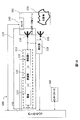
いくつかの実施形態では、RFエネルギーは、対象物の処理前、処理中および/または処理後に、対象物の1つまたは複数の処理状態を検知する(すなわち、検出する、モニタするなど)ために印加することができる。いくつかの実施形態では、処理状態は、RFフィードバックをモニタすることによって検知する(検出する)ことができる。RFフィードバックは、RFエネルギー印加に応答して受信することができる。対象物の1つまたは複数の処理状態を検知するためのRFエネルギー印加装置については、図1Aおよび1Bに図式的に提示される。いくつかの実施形態では、RFエネルギーは、対象物103の初期状態を検出および決定するため、処理前に対象物103に印加することができる。RFエネルギーは、例えば、対象物の処理(例えば、加熱)が原因で起こる対象物の変化をモニタするため、処理中に対象物103に印加することができる。そのような変化のいくつかの例は、様相変化(例えば、冷凍対象物の解凍)、反応剤溶液の反応の進行に起因するpH変化、硬化に起因する重合体の重合、タンパク質の変質(例えば、卵ベースの料理およびペイストリーの調理における、ならびに、肉の調理における)、様々な調理状態(例えば、パン生地のベーキング)などを含み得る。これらの変化は、対象物の1つまたは複数の処理状態と関連付けることができる。また、RFエネルギーは、例えば、プロセスを終了すべきかどうかを決定するため、処理の終了間近または終了時に印加することもできる。
In some embodiments, RF energy is used to sense (ie, detect, monitor, etc.) one or more processing states of an object before, during and / or after processing of the object. Can be applied. In some embodiments, the processing state can be detected (detected) by monitoring RF feedback. RF feedback can be received in response to RF energy application. An RF energy application device for detecting one or more processing states of an object is schematically presented in FIGS. 1A and 1B. In some embodiments, RF energy can be applied to the
いくつかの実施形態では、RFエネルギーは、対象物の処理の間、対象物103の処理状態(例えば、少なくとも1つの処理状態インジケータによって示される)とエネルギー印加ゾーンから受信されたRFフィードバックとを相関させるため、印加することができる(例えば、装置100において)。処理状態インジケータは、対象物の処理状態に関する情報をコントローラに伝えるよう構成された任意のメカニズムを含み得る。例えば、処理状態インジケータは、例えば、温度センサ、湿度センサなど、対象物の処理状態を示す、1つもしくは複数の状態、属性などを検知するよう構成された1つもしくは複数のセンサを備えることができるか、または、同センサであり得る。それに加えてまたはその代替として、処理状態インジケータは、対象物の処理状態の表示をユーザから受信し、コントローラにこの表示を伝えるよう構成されたユーザインターフェースを備えることができるか、または、同ユーザインターフェースであり得る。 In some embodiments, the RF energy correlates the processing state of the object 103 (eg, as indicated by at least one processing state indicator) with the RF feedback received from the energy application zone during processing of the object. Can be applied (eg, in apparatus 100). The processing status indicator may include any mechanism configured to communicate information about the processing status of the object to the controller. For example, the processing status indicator may comprise one or more sensors configured to detect one or more statuses, attributes, etc. that indicate the processing status of the object, such as a temperature sensor, a humidity sensor, etc. Or can be the same sensor. Additionally or alternatively, the processing status indicator may comprise a user interface configured to receive an indication of the processing status of the object from the user and communicate this indication to the controller, or the user interface It can be.
処理状態の表示は、エネルギー印加ゾーンに提供される1つまたは複数のセンサによって検知することも、インターフェースを通じてユーザが提供することもできる。処理状態の表示は、対象物の処理前、処理中または処理後の対象物の量的な(例えば、温度、圧力など)または非量的な(例えば、色、仕上がり具合、味、調理状態など)対象物の物理的または化学的特性のいかなる測定値も含み得る。処理状態の表示は、センサ(例えば、センサ140)によって測定する(検知する)ことも、ユーザによる検査を通じて決定することもできる。装置100は、対象物の処理状態の表示をユーザから受信するよう構成された第1のユーザインターフェース(例えば、インターフェース160)をさらに含み得る。対象物の処理状態を示す量的変数のいくつかの例は、温度、湿度、圧力、流量、pH、化学組成、密度、重量、体積などを含み得る。処理状態を示す測定可能な非量的変数のいくつかの例は、色、味、調理状態、仕上がりレベルなどを含み得る。本明細書で使用される場合、調理状態は、食品のいかなる調理/処理形態(例えば、ロースト、ベーキング、煮沸、スチーミング、グリル、長時間の煮込み、解凍、焦げ目付け、パン生地の発酵など)の間にも食品に関連して起こり得る所望のまたは非所望の何れかの対象物の可能ないかなる状態も指し得る。調理状態のいくつかの例は、パン生地のベーキングの終了時、肉の長時間の煮込みもしくはでんぷんを多く含む野菜の調理における軟化段階の開始時および終了時、イースト生地の発酵の終了時、様々なベーキング製品の焦げ目付けの終了時、様々な肉類の仕上がり具合、または、他のタイプの調理プロセスの程度などを含み得る。
The indication of the processing status can be detected by one or more sensors provided in the energy application zone or can be provided by the user through the interface. The display of the processing state is quantitative (for example, temperature, pressure, etc.) or non-quantity (for example, color, finish, taste, cooking state, etc.) of the target before, during or after processing of the target. ) May include any measurement of the physical or chemical properties of the object. The display of the processing state can be measured (detected) by a sensor (eg, sensor 140) or can be determined through inspection by a user. The
対象物の1つまたは複数の処理状態の検知(すなわち、検出、モニタリングなど)は、対象物からRFフィードバックを受信するためにエネルギー印加ゾーン(例えば、ゾーン102)にRFエネルギーを印加することによって実行することができる。RFフィードバックは、対象物の1つまたは複数の処理状態と相関させることができる。RFフィードバックと対象物の1つまたは複数の処理状態とを相関させるための方法330は、図3Cを参照して説明される。相関は、例えば、装置100と関連付けられたメモリ(例えば、コントローラ150と関連付けられたメモリ)上または機械可読要素(例えば、バーコード)上に記録することができる。
Sensing one or more processing states of an object (ie, detection, monitoring, etc.) is performed by applying RF energy to an energy application zone (eg, zone 102) to receive RF feedback from the object. can do. The RF feedback can be correlated with one or more processing states of the object. A
本明細書で使用される場合、RFフィードバックは、受信されたいかなるRF信号も、1つまたは複数の受信されたRF信号に基づいて計算されたいかなる値も(空洞で励起されたEM場に対する空洞および/または対象物の誘電応答を示し得る)含み得る。RFフィードバックは、励起設定依存性であり得、例えば、異なる励起設定にわたって変化する値を含み得る。RFフィードバックは、未処理のRFフィードバックおよび演算済みのRFフィードバックを含み得る。未処理のRFフィードバックは、例えば、入出力電力レベル、場の強度、ネットワークパラメータ、例えば、空洞の散乱(S)パラメータ、アドミタンス(Y)パラメータ、反射および透過係数、インピーダンスなど、直接測定可能なパラメータを含み得る。演算済みのRFフィードバックは、例えば、直接測定可能なパラメータ間の和、積、商および/または差、散逸率値(DR)(以下で論じられるような)、直接測定可能なパラメータまたは演算済みのパラメータの平均(例えば、時間平均および/または励起設定平均)、直接測定可能なパラメータまたは演算済みのパラメータの微分係数(例えば、時間微分係数および/または励起設定微分係数)など、2つ以上の直接測定可能なパラメータまたは値に関するいかなる数学的操作の結果も含み得る。励起設定の概念については、以下で幅広く論じられる。 As used herein, RF feedback can be any received RF signal, any value calculated based on one or more received RF signals (cavity versus EM field excited in the cavity). And / or may exhibit a dielectric response of the object). The RF feedback may be excitation setting dependent and may include values that vary across different excitation settings, for example. RF feedback may include raw RF feedback and computed RF feedback. Raw RF feedback is a directly measurable parameter such as, for example, input / output power level, field strength, network parameters such as cavity scattering (S) parameters, admittance (Y) parameters, reflection and transmission coefficients, impedance, etc. Can be included. Computed RF feedback can be, for example, a sum, product, quotient and / or difference between directly measurable parameters, dissipation factor value (DR) (as discussed below), directly measurable parameter or computed Two or more direct, such as parameter average (eg, time average and / or excitation set average), directly measurable parameter or computed parameter derivative (eg, time derivative and / or excitation set derivative) It may include the result of any mathematical operation on a measurable parameter or value. The concept of excitation settings is discussed extensively below.
いくつかの実施形態では、RFフィードバックは、RFエネルギー(すなわち、RF範囲のEMエネルギー)印加に応答し易いものであり得る。RFエネルギーは、対象物によって少なくとも部分的に占有されるエネルギー印加ゾーンに印加することができる。RFフィードバックを受信するために印加されるRFエネルギーは、例えば、低電力レベルの、比較的少量のエネルギーであり得る。本明細書で使用される場合、少量のエネルギーは、対象物の処理がほとんどもしくは全く起こらない、またはそうでなければ、低過ぎて所望の処理程度を提供することができないエネルギーの量を指し得る。例えば、いくつかの実施形態では、少量のエネルギーは、対象物の少なくとも1つの検出可能な処理状態における変化(またはある程度の変化)を引き起こすには不十分であり得る。いくつかの実施形態では、対象物を処理する(例えば、加熱する)ためのRFエネルギーの印加は、一励起設定当たりの第1の平均エネルギー量で行うことができ、RFフィードバックを受信するためのRFエネルギーの印加は、一励起設定当たりの第2の平均エネルギー量で行うことができ、一励起設定当たりの第1の平均エネルギー量は、一励起設定当たりの第2の平均エネルギー量より高い。 In some embodiments, the RF feedback may be responsive to application of RF energy (ie, RF range EM energy). The RF energy can be applied to an energy application zone that is at least partially occupied by the object. The RF energy applied to receive RF feedback can be a relatively small amount of energy, for example, at a low power level. As used herein, a small amount of energy can refer to an amount of energy that causes little or no processing of the object or is otherwise too low to provide the desired degree of processing. . For example, in some embodiments, a small amount of energy may be insufficient to cause a change (or some change) in at least one detectable processing state of the object. In some embodiments, application of RF energy to treat (eg, heat) an object can be performed with a first average amount of energy per excitation setting and for receiving RF feedback. The application of RF energy can be performed with a second average energy amount per excitation setting, where the first average energy amount per excitation setting is higher than the second average energy amount per excitation setting.
RFフィードバックは、エネルギー印加ゾーンにまたはその周辺に配置された検出器(例えば、検出器118、118a、128、138)またはセンサ(例えば、センサ140)によって、RFエネルギー印加に応答して受信される信号を含み得る。信号は、RFエネルギー印加と関連付けられたいくつかのまたはすべての直接測定可能なパラメータを含み得る。エネルギーは、少なくとも1つの放射素子(例えば、図1Aおよび1Bに示される素子110)供給することができ、エネルギーは、RFエネルギーの印加に応答して、エネルギー印加ゾーンから、放出側の放射素子に反射し返すことができる。それに加えてまたはその代替として、エネルギーは、他の放射素子(例えば、図1Aに示される素子111ならびに図1Bに示される素子120および130)と結合することができる。RFエネルギー印加に応答して受信することができるRFフィードバックの様々な例については、以下で論じられる。
RF feedback is received in response to RF energy application by a detector (eg,
いくつかの実施形態では、対象物の処理(例えば、対象物へのエネルギー印加による)は、受信されたRFフィードバックおよび/または検出された処理状態に基づいて制御することができる。例えば、エネルギーの量(例えば、従来の調理用オーブンの温度または電子レンジの電力レベル)またはエネルギー印加の継続時間(例えば、エネルギー印加の時間の長さ)は、受信されたRFフィードバック(例えば、演算済みのRFフィードバック)に基づいて決定することができる。例示的な実施形態では、演算済みのRFフィードバックは、従来のオーブンにおける熱の印加の間(例えば、ベーキングの間)、モニタすることができる。演算済みのRFフィードバックは、第1の温度(例えば、180℃)での食品の加熱の間、ある程度まで食品が調理されたことを演算済みのRFフィードバックが示すまでモニタすることができ、その後、熱印加を終了することができる。 In some embodiments, processing of an object (eg, by applying energy to the object) can be controlled based on received RF feedback and / or detected processing conditions. For example, the amount of energy (eg, the temperature of a conventional cooking oven or the power level of a microwave oven) or the duration of energy application (eg, length of time of energy application) can be received RF feedback (eg, computed Based on the RF feedback). In an exemplary embodiment, the computed RF feedback can be monitored during the application of heat (eg, during baking) in a conventional oven. The computed RF feedback can be monitored during the heating of the food at a first temperature (eg, 180 ° C.) until the computed RF feedback indicates that the food has been cooked to some extent, Heat application can be terminated.
いくつかの実施形態では、対象物を処理するためにエネルギーが印加されるプロトコルは、RFフィードバック(例えば、演算済みのRFフィードバック)に基づいて決定することができる。本明細書で使用される場合、プロトコルは、例えば、対流加熱における加熱の温度および継続時間(例えば、温度T1でS1秒間加熱した後、温度T2でS2秒間加熱するなど)、IR加熱における電力および時間など、エネルギー印加を制御するパラメータのうちの1つまたは複数を含み得る。対象物を処理するためにRFエネルギーが印加される際、プロトコルは、RFエネルギーレベル(例えば、電力レベルおよび/または継続時間)を設定すること、および/または、複数の励起設定から1つもしくは複数の励起設定を選択すること、ならびに、選択された励起設定でRFエネルギーを印加すること、エネルギー印加に対する1つもしくは複数の規則をRFフィードバックの関数として適用することなどを含み得る。エネルギーは、第1のプロトコルを使用して印加して、対象物を処理することができる(例えば、温度および時間を食品の調理用に設定することができる)。RFフィードバックは、エネルギー印加の間、1つまたは複数のRFフィードバック値が対象物の第1の処理状態(例えば、食品は調理済み)を示す閾値(すなわち、第1の基準)に達するまでモニタすることができる。RFフィードバック値が閾値に達した後、食品の焦げ目付けのため、短時間温度を上昇させる(例えば、220℃まで)ことによって、第2のプロトコルを適用することができる。処理の1つもしくは複数の状態(例えば、第2の状態)が目標値に達したか、または、第2の基準(例えば、所望の温度、所望の仕上がり具合または目標pHなど)が満たされたことをモニタされたRFフィードバックが示すと、処理(例えば、加熱)を終了することができる(すなわち、第3のプロトコル)。RFフィードバックに基づいて対象物へのエネルギー印加を制御するための例示的な方法300および310については、図3Aおよび3Bに開示され、基準に基づいてRFエネルギー印加を制御するための例示的な方法400については、図4に開示される。
In some embodiments, the protocol in which energy is applied to process the object can be determined based on RF feedback (eg, computed RF feedback). As used herein, protocols include, for example, the temperature and duration of heating in convection heating (eg, heating for 1 second at temperature T 1 followed by heating for 2 seconds at temperature T 2 ), IR One or more of the parameters that control energy application, such as power and time in heating, may be included. When RF energy is applied to treat an object, the protocol sets the RF energy level (eg, power level and / or duration) and / or one or more from multiple excitation settings. Selecting RF excitation settings, as well as applying RF energy at the selected excitation settings, applying one or more rules for energy application as a function of RF feedback, and the like. Energy can be applied using the first protocol to process the object (eg, temperature and time can be set for cooking food). RF feedback is monitored during energy application until one or more RF feedback values reach a threshold (ie, a first criterion) indicative of a first processing state of the object (eg, food is cooked). be able to. After the RF feedback value reaches the threshold, the second protocol can be applied by increasing the temperature for a short time (eg, up to 220 ° C.) for food scorching. One or more states of the process (eg, second state) have reached a target value or a second criterion (eg, desired temperature, desired finish, or target pH, etc.) has been met Once the monitored RF feedback indicates that the process (eg, heating) can be terminated (ie, the third protocol).
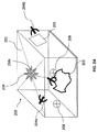
ある実施形態では、RFエネルギーは、エネルギー印加ゾーンに印加することができる(例えば、対象物の少なくとも1つの処理状態を検知するため)。例えば、RFエネルギーは、図1Aおよび1Bに示されるエネルギー印加ゾーン102などのエネルギー印加ゾーンに印加することができる。上記に示されるように、対象物を処理するため、他のエネルギータイプ(例えば、対流および/またはIR)をゾーンに印加することができる。エネルギー印加ゾーン102は、対象物を処理するためにエネルギーを印加することができるいかなる空洞、空隙、場所、領域またはエリアも含み得る。いくつかの実施形態では、RFエネルギーは、対象物の処理状態を検知および/または検出するために印加することができる。ゾーンは、中空でも、液体、固体、気体で充填または部分的に充填されても、その組合せでもあり得る。単なる例示として、エネルギー印加ゾーン102は、EM波の存在、伝播および/または共振を可能にする、エンクロージャの内部、部分的なエンクロージャの内部、オープン空間、固体または部分的固体を含み得る。ゾーン102は、コンベアベルトまたは回転板を含み得る。いくつかの実施形態では、ゾーン102は、空洞(例えば、図2Aに示されるような例示的な空洞200)を含むか、または、同空洞であり得る。
In certain embodiments, RF energy can be applied to the energy application zone (eg, to detect at least one processing state of the object). For example, RF energy can be applied to an energy application zone, such as the
ある実施形態では、EMエネルギーは、エネルギー印加ゾーン(例えば、エネルギー印加ゾーン102)に配置された対象物(例えば、図1Aの対象物103)の処理状態を検知および検出するために印加することができる。対象物は、対象物の少なくとも一部がゾーンに位置する場合、または、対象物のある部分が印加されたEM放射を受ける場合に、エネルギー印加ゾーンに位置すると見なすことができる。処理のためにEMエネルギーを印加することができる対象物のタイプは、対象物の特定の形態に限定されない。対象物は、開示される実施形態が利用される特定のプロセスに応じて、液体、準液体、固体、準固体または気体を含み得る。また、対象物は、異なる様相の物質の複合体または混合物も含み得る。したがって、非限定的な例として、対象物という用語は、解凍もしくは調理すべき食料、乾燥すべき衣服もしくは他の湿潤物、解凍すべき冷凍器官、反応させるべき化学物質、燃焼すべき燃料もしくは他の可燃物、脱水すべき水和物、膨張させるべき気体、加熱、沸騰もしくは蒸発させるべき液体、または、名目上でも、エネルギー(例えば、EMエネルギー)の印加が所望される他の任意の材料などの物質を包含し得る。
In some embodiments, EM energy may be applied to sense and detect the processing state of an object (eg,
いくつかの実施形態では、エネルギー印加ゾーン102に印加されたRFエネルギーの一部は、対象物103によって吸収(散逸)され得る。いくつかの実施形態では、エネルギー印加ゾーン102に印加されたEMエネルギーの別の部分は、様々な要素(例えば、食料の残留物、粒子の残留物、追加の対象物、ゾーン102と関連付けられた構造)、または、ゾーン102に見られるかもしくはエネルギー印加ゾーン102と関連付けられた他の任意のEMエネルギー吸収物質によって吸収され得る。また、エネルギー印加ゾーン102は、損失構成要素も含み得、損失構成要素は、それら自体は大量のEMエネルギーを吸収することはないが、EMエネルギー損失の原因となる。そのような損失構成要素は、例えば、割れ目、継ぎ目、接合部、ドア、空洞本体とドアとの間の界面、または、エネルギー印加ゾーン102と関連付けられた他の任意の損失機構を含み得る。したがって、いくつかの実施形態では、ゾーンで散逸されたエネルギーは、エネルギー印加ゾーンのEMエネルギー吸収構成要素とともに、対象物103の少なくとも一部、および、ゾーンと関連付けられたEMエネルギー損失構成要素で散逸されたエネルギーを含み得る。
In some embodiments, some of the RF energy applied to the
例示的なエネルギー印加ゾーン102は、オーブン(例えば、調理用オーブン)、チャンバ、タンク、乾燥機、解凍機、脱水機、リアクタ、エンジン、化学的または生物学的な処理装置、パイプ(例えば、燃料パイプ)、炉、焼却炉、材料成形または形成装置、コンベア、燃焼ゾーン、フィルタ、クーラー、冷凍庫などのエネルギーが印加される場所を含み得る。いくつかの実施形態では、エネルギー印加ゾーンは、対象物が購入された時点で処理される自動販売機の一部であり得る。
Exemplary
図1Aおよび1Bは、例えば、対象物の処理の間、ゾーン102に配置された対象物にRFエネルギーを印加するため(例えば、対象物の1つまたは複数の処理状態を検出するため)の装置100の図表示を含む。RFエネルギーは、RF範囲の周波数で印加されるEMエネルギーを含み得る。装置100は、エネルギー印加ゾーン102にRFエネルギーを印加するよう構成された少なくとも1つの放射素子110を含み得る。放射素子110は、RFエネルギーを伝達(放出)するよう設計または構成されたいかなる素子も、システムも、素子のアレイなども含み得る。例えば、放射素子110は、いかなるアンテナも、アンテナのアレイも、RFフィードも、導波路も、遅波アンテナも、パッチアンテナも、逆Fアンテナなども、それらの任意の組合せまたは数で含み得る。現在開示される実施形態では、複数のアンテナおよび/または複数の放射素子(例えば、アンテナ)を提供することができる(例えば、図1Aに示される放射素子110および111、または、図1Bに示される放射素子110、120、および130)。エネルギー印加ゾーン102は、定義表面を備えたエンクロージャを含み得る。放射素子は、ゾーン102(例えば、空洞壁)を定義する1つまたは複数の表面上に位置し得る。例えば、放射素子110および130は、エネルギー印加ゾーン102の2つの異なる(例えば、対向する)表面上に位置し得る。いくつかの実施形態では、放射素子のうちの1つまたは複数は、ゾーン102内部に位置することも(例えば、素子130)、ゾーン102内部に部分的に位置することも(例えば、素子110および111)あり得る。それに加えてまたはその代替として、放射素子は、エネルギー印加ゾーンの外側に位置し得る(例えば、素子120)。放射素子のうちの1つまたは複数(例えば、素子130)は、対象物103に近接することも、対象物103と接触することも、対象物103の近くにあることも、対象物103に埋め込まれることさえもあり得る(例えば、対象物が液体またはフィルタを含む場合、例えば、図2Aに示される放射素子204c)。各放射素子の向き、タイプ、寸法および/または構成は、特定の応用に基づいて、例えば、所望の標的効果に基づいて、異なっていても同じでもよい。各放射素子は、同じ方向または様々な異なる方向に沿ってEM波を放出するように配置、調整および/または方向付けすることができる。その上、各放射素子の場所、向きおよび構成は、エネルギーを対象物に印加する前に事前に決定することができる。その代替としてまたはそれに加えて、各放射素子の場所、向きおよび/または構成は、装置の動作の間および/またはエネルギー印加のラウンド/サイクル間に、例えば、コントローラ(例えば、コントローラ150)を使用することによって、動的に調整することができる。いかなる構造または構成の放射素子も、開示される実施形態で使用することができる。
1A and 1B illustrate an apparatus for applying RF energy to an object disposed in
図1Aに示されるように、装置100は、エネルギー印加ゾーン102にRFエネルギーを放出するための少なくとも1つの放射素子110と、エネルギー印加ゾーン102からEMエネルギーを受け取るよう構成することができる少なくとも1つの放射素子111とを含み得る。放射素子は、特定の応用または構成に応じて、エミッタ、レシーバまたはその両方として機能し得る。放射素子がエネルギー印加ゾーンからのRFエネルギーのレシーバとして動作する場合(例えば、受信、反射および/または結合されたEM波)、放射素子は、エネルギー印加ゾーンからまたは他の放射素子からRFエネルギーを受け取る。いくつかの実施形態では、放射素子110は、エミッタおよびレシーバとして機能し得る。
As shown in FIG. 1A, the
本発明のいくつかの態様は、対象物の1つまたは複数の処理状態を検出するために、放射素子からエネルギー印加ゾーン102に放出されるRFエネルギー、放出側の放射素子に供給されるRFエネルギー、または、エネルギー印加ゾーンから放射素子(例えば、素子110および111)によって受け取られたRFエネルギーの検出、測定、モニタリングまたは検知に関与し得る。放出および/または受け取られた(例えば、反射または結合された)RFエネルギーの様々なRFフィードバックを測定および/または検出および/または計算するよう構成された検出器は、少なくとも1つの放射素子と関連付けることができる。いくつかの実施形態では、検出器は、放射素子と関連付けられるか、または、放射素子に接続される方向性結合器を含み得る。検出器は、放出および/または受け取られたRFエネルギーに関連するRFフィードバック(例えば、未処理のRFフィードバック)を検出および/または測定することができる。未処理のRFフィードバックは、対象物の1つまたは複数の処理状態と関連付けることができる。未処理のRFフィードバックは、例えば、電力、周波数、エネルギー、電流、電圧、放出間の位相など、RF放出のすべての検出可能なパラメータを含み得る。例えば、図1Aに示される検出器118は、放射素子110および111と関連付けることができる。検出器118は、例えば、素子110からのRFエネルギー放出に応答し易い、素子111に関連する1つまたは複数のパラメータを測定または検出するよう構成することができる。いくつかの実施形態では、検出器118は、素子110からのRFエネルギー放出の結果として、ゾーン102から素子110に受け取られた(例えば、反射し返された)RFエネルギーのパラメータを検出するよう構成することができる。また、検出器118は、放射素子110および111のポートで電圧および電流を測定する適切なタイプの回路またはデバイスも含み得る。いくつかの実施形態では、検出器118は、放射素子がエミッタとして機能する際に、RF源(例えば、供給源112)から放射素子への信号のフローを可能にし、放射素子がレシーバとして機能する際に、放射素子から検出器への信号のフローを可能にするよう構成された方向性結合器を含み得る。検出器118は、演算済みのRFフィードバックを受信する(得る)ため、未処理のRFフィードバックの数学的操作を実行するよう構成されたコントローラをさらに含み得る。その代替としてまたはそれに加えて、演算済みのRFフィードバックは、コントローラ150によって計算することができ、検出器は、さらなる操作のために未処理のRFフィードバックをコントローラ150に送信することができる。
Some aspects of the present invention provide RF energy emitted from the radiating element to the
いくつかの実施形態では、検出器118は、2つの素子(例えば、素子110および111)と関連付けることができる。いくつかの実施形態では、各素子は、1つの検出器と関連付けることができる。例えば、素子110、120および130は、図1Bに示される検出器118a、128および138と関連付けることができる。検出器118a、128および138は、放出されたRFエネルギーおよびゾーン102から受け取られたRFエネルギーの両方のRFエネルギーパラメータを検出するよう構成することができる。例えば、RFエネルギーは、素子110からゾーン102に放出することができる。その結果、RFエネルギーの一部は、対象物103によって吸収されるかまたは対象物103において散逸される場合があり、別の部分は、ゾーン102から反射し返されるかまたは結合され、素子110、120および130によって受け取られる場合がある。
In some embodiments, the
いくつかの開示される実施形態と一致して、RFエネルギーは、RF源112から1つまたは複数の放出側の放射素子に供給することができる。RF源112から放出側の放射素子(例えば、素子110)に供給されたエネルギーは、供給エネルギーと呼ぶことができ、SEと示される。
Consistent with some disclosed embodiments, RF energy can be supplied from the
供給されたRFエネルギーの一部は、対象物(例えば、対象物103)によって吸収され得る。エネルギーのこの部分は、吸収エネルギーまたは散逸エネルギーと呼ぶことができ、AEと示される。 Some of the supplied RF energy can be absorbed by an object (eg, object 103). This portion of energy can be referred to as absorbed energy or dissipated energy and is denoted AE.
供給されたRFエネルギーの一部分は、放出素子(例えば、素子110)に反射し返される場合がある。エネルギーのこの部分は、反射エネルギーと呼ぶことができ、REと示される。反射エネルギーは、放射素子とエネルギー印加ゾーンとの間の界面で反射され得る。その代替としてまたはそれに加えて、反射エネルギーは、例えば、対象物からまたはゾーンを定義する壁からなど、エネルギー印加ゾーンから反射される(例えば、インピーダンス不整合に起因して)エネルギーを含み得る。 A portion of the supplied RF energy may be reflected back to the emitting element (eg, element 110). This part of the energy can be referred to as reflected energy and is denoted RE. The reflected energy can be reflected at the interface between the radiating element and the energy application zone. Alternatively or additionally, the reflected energy may include energy reflected from an energy application zone (eg, due to impedance mismatch), eg, from an object or from a wall defining the zone.
供給エネルギーの他の部分は、エネルギー印加ゾーンにおいて他の放射素子またはセンサ(例えば、受信側の放射素子(例えば、素子111)、別の放出側の放射素子(例えば、120および130)、センサ(例えば、センサ140))と結合され得、結合エネルギーと呼ぶことができ、CEと示される。 Other parts of the supplied energy may be other radiating elements or sensors (eg, receiving radiating elements (eg, element 111), other emitting radiating elements (eg, 120 and 130), sensors ( For example, it can be coupled with sensor 140)) and can be referred to as binding energy and is denoted CE.
いくつかの実施形態では、供給されたRFエネルギー(SE)は、放出側の放射素子に反射し返されたエネルギー(RE)、対象物において吸収されたエネルギー(AE)、他の放射素子のうちの1つまたは複数と結合されたエネルギー(CE)を含み得る。方程式(1)は、以下のように、量SEと、REと、AEと、CEとの関係を表し得る。
(1) SE=RE+AE+CE
In some embodiments, the supplied RF energy (SE) is the energy reflected back to the emitting radiating element (RE), the energy absorbed in the object (AE), of other radiating elements Energy (CE) associated with one or more of the above. Equation (1) may represent the relationship between quantities SE, RE, AE, and CE as follows:
(1) SE = RE + AE + CE
放射素子に供給されたエネルギー量とその放射素子に反射し返されたエネルギー量との差は、送達エネルギーと呼ぶことができ、DEと示される。1つまたは複数の検出器(例えば、検出器118、118a、128および138)は、供給、反射および結合されたエネルギーの値を検出および測定するよう構成することができ、コントローラ(例えば、コントローラ150)は、例えば、方程式(1)に基づいて、送達および/または吸収されたエネルギーの量を決定するよう構成することができる。これにより、以下の方程式が生じ得る。
(2a) AE=SE−(RE+CE)
(2b) DE=SE−RE
(2c) DE=AE+CE
The difference between the amount of energy supplied to the radiating element and the amount of energy reflected back to that radiating element can be referred to as delivery energy and is denoted DE. One or more detectors (eg,
(2a) AE = SE− (RE + CE)
(2b) DE = SE-RE
(2c) DE = AE + CE
装置100は、RFエネルギーを放射素子に供給するための供給源をさらに含み得る。例えば、供給源112は、放出素子110にRFエネルギーを供給することができ、供給源122は、放出素子120にRFエネルギーを供給することができ、供給源132は、放出素子130にRFエネルギーを供給することができる。
The
本発明のいくつかの実施形態によれば、装置または方法は、RFエネルギーをエネルギー印加ゾーンに供給するよう構成された少なくとも1つの供給源の使用に関与し得る。供給源は、RFエネルギーの生成および供給に適切であり得るいかなるコンポーネントも含み得る。例えば、供給源112は、RF電源(例えば、電源113)を含み得る。さらに別の例では、供給源は、複数の電源(例えば、113、123および133)を含み得る。電源の各々は、EMエネルギーを運ぶEM波を生成するよう構成することができる。例えば、電源113(または123または133)は、既定の波長または周波数で高出力マイクロ波を生成するよう構成されたマグネトロンを含み得る。その代替としてまたはそれに加えて、電源113(または123または133)は、制御可能な周波数でAC波形(例えば、AC電圧または電流)を生成するよう構成された半導体発振器(例えば、電圧制御発振器)を含み得る。周波数は、一定であるようにまたは変化するように制御することができる。AC波形は、正弦波、矩形波、パルス波、三角波、または、交互に変わる極性を有する別のタイプの波形を含み得る。その代替としてまたはそれに加えて、RFエネルギーの供給源は、例えば、EM場生成器、EM束生成器、または、振動電子を生成するための任意のメカニズムなど、他の任意の電源を含み得る。供給源は、ソリッドステート増幅器を含み得る。
According to some embodiments of the invention, the apparatus or method may involve the use of at least one source configured to supply RF energy to the energy application zone. The source may include any component that may be suitable for generating and supplying RF energy. For example,
いくつかの実施形態と一致して、RFエネルギーは、既定の波長または周波数での伝播RF波の形態で(RF放射としても知られている)エネルギー印加ゾーンに供給することができる。本明細書で使用される場合、伝播RF波は、共振波、進行波、エバネッセント波、および、他の任意の方法で媒体中を進行する波を含み得る。RF放射は、相互作用する物質に与えられる(または物質中に散逸される)エネルギーを運ぶ。 Consistent with some embodiments, RF energy can be delivered to an energy application zone (also known as RF radiation) in the form of a propagating RF wave at a predetermined wavelength or frequency. As used herein, propagating RF waves may include resonant waves, traveling waves, evanescent waves, and waves that travel through the medium in any other way. RF radiation carries energy that is imparted to (or dissipated into) the interacting material.
いくつかの実施形態では、供給源(例えば、供給源112、122または132)は、少なくとも1つの変調器(例えば、変調器115、125または135)および/または少なくとも1つの増幅器(例えば、増幅器116、126または136)をさらに含み得る。変調器は、位相変調器、周波数変調器、振幅変調器、発振器、または、放射素子に供給されるRFエネルギーの少なくとも1つの態様を変調するよう構成された他の任意の変調器を含み得る。増幅器は、電源によって供給されるRF波の振幅を変更する(例えば、増幅する)よう構成されたいかなる装置も含み得る。供給源(例えば、供給源112、122または132)は、特定の実施形態の要件に従って、単に1つのコンポーネントを含むことも、複数のコンポーネントを含むことも、コンポーネントの任意の組合せを含むこともあり得ることに留意されたい。電源、変調器および/または増幅器は各々、コントローラ(例えば、コントローラ150)によって制御することができ、以下でさらに詳細に論じられる。
In some embodiments, the source (eg,
装置100は、センサ140などの少なくとも1つのセンサをさらに含み得る。センサ140は、エネルギー印加ゾーン102にまたはその周辺に設置することができる。いくつかの実施形態では、センサ140は、例示的な処理状態インジケータを構成し得る。センサ140は、本発明のいくつかの実施形態に従って、RFフィードバックを検出および/または測定するよう構成することができる。例えば、センサ140は、エネルギー印加ゾーンで励起されたEM場の強度をモニタするよう構成することができる。それに加えてまたはその代替として、センサ140は、対象物の1つまたは複数の処理状態またはエネルギー印加ゾーンを示す他の信号またはフィードバックを検出および/または測定するよう構成することができる。例えば、センサ140は、対象物および/またはエネルギー印加ゾーンと関連付けられた温度を測定するよう構成された温度計(例えば、熱電対またはIRセンサ)を含み得る。センサ140は、湿度センサ、圧力センサ(例えば、バロメータ)、溶液のpH値を測定するよう構成されたpHセンサ(例えば、対象物が液体を含む場合)、流量計などを含み得る。センサ140は、対象物の少なくとも一部分の重量を測定するよう構成することができる(例えば、測量計)。センサ140は、対象物またはエネルギー印加ゾーンの検出可能および測定可能ないかなる特性(例えば、処理状態のインジケータ)も測定するよう構成することができる。センサ140は、コントローラ150にフィードバック信号を送信するよう構成することができる。いくつかの実施形態では、2つ以上のセンサ140が提供され得る。2つ以上のセンサ140は、1つまたは複数の異なるタイプまたは同じタイプのセンサを含み得る(例えば、温度センサ、温度を検出するための光ファイバ、重量センサなどが提供され得る)。本発明のいくつかの態様は、対象物103の処理状態を示すセンサ140で検出された信号と、センサ140から受信された信号と並行してまたはそれに加えて、検出器118、118a、128および/または138によって検知、モニタまたは検出されたRFフィードバックとの、例えば、コントローラ150による、相関に関与し得る。
いくつかの実施形態では、装置100は、コントローラ(例えば、コントローラ150)を含み得る。コントローラ150は、プロセッサと一致する場合も、プロセッサの一部である場合もあり得る。本明細書で使用される場合、「プロセッサ」という用語は、入力上で論理演算を実行する電気回路を含み得る。例えば、そのようなプロセッサは、1つまたは複数の集積回路、マイクロチップ、マイクロコントローラ、マイクロプロセッサ、中央演算処理装置(CPU)のすべてもしくは一部、グラフィック処理装置(GPU)、デジタル信号プロセッサ(DSP)、フィールドプログラマブルゲートアレイ(FPGA)、または、命令の実行もしくは論理演算の実行に適切な他の回路を含み得る。
In some embodiments,
コントローラによって実行される命令(例えば、1つまたは複数のスクリプトまたはエネルギープロトコル)は、例えば、コントローラと統合されるかまたはコントローラに埋め込まれたメモリユニットに事前にロードすることも、RAM、ROM、ハードディスク、光ディスク、磁気媒体、フラッシュメモリ、他の永久、固定もしくは揮発性メモリ、または、コントローラのために命令を格納することができる他の任意のメカニズムなどの別のメモリユニットに格納することもできる。別のメモリユニットは、コントローラの一部であっても、一部でなくともよい。コントローラは、特定の使用のためにカスタム設計することも、一般用途用に構成して、異なるソフトウェアを実行することによって異なる機能を実行できるようにすることもできる。 The instructions (eg, one or more scripts or energy protocols) executed by the controller can be preloaded into a memory unit that is integrated with the controller or embedded in the controller, for example, RAM, ROM, hard disk It can also be stored in another memory unit, such as an optical disk, magnetic medium, flash memory, other permanent, fixed or volatile memory, or any other mechanism capable of storing instructions for the controller. Another memory unit may or may not be part of the controller. The controller can be custom designed for a particular use, or it can be configured for general use to perform different functions by running different software.
複数のコントローラまたはプロセッサを使用する場合、すべてが、互いに電気的に接続されるかまたは切断される同様の構造のものであっても、異なる構造のものであってもよい。複数のコントローラまたはプロセッサは、別々の回路であっても、単一回路に統合されてもよい。複数のコントローラまたはプロセッサを使用する場合、複数のコントローラまたはプロセッサは、独立して動作するようまたは協力して動作するよう構成することができる。複数のコントローラまたはプロセッサは、電気的に、磁気的に、光学的に、音響的に、機械的に、または、相互作用を可能にする他の手段で結合することができる。 When using multiple controllers or processors, all may be of similar structure or connected differently from one another or disconnected from one another. Multiple controllers or processors may be separate circuits or integrated into a single circuit. When multiple controllers or processors are used, the multiple controllers or processors can be configured to operate independently or in concert. Multiple controllers or processors can be coupled electrically, magnetically, optically, acoustically, mechanically, or other means that allow interaction.
本発明のいくつかの実施形態による装置は、1つまたは複数のRFエネルギー印加ユニット(例えば、図1Aおよび1Bに示されるユニット119および119a)を含み得る。エネルギー印加ユニット(例えば、ユニット119a)は、1つまたは複数の放射素子(例えば、素子110、120および130)と、RFエネルギーを放射素子に供給するRFエネルギー源とを含み得る。いくつかの実施形態では、RFエネルギー印加ユニット119aは、2つ以上の同期RFエネルギー源(例えば、供給源112、122および132)を含み得、同期RFエネルギー源は、例えば、コントローラ150が制御して、制御位相差で、制御振幅差でなど、共通の周波数を有する信号を放射素子に供給することができる。いくつかの実施形態では、ユニット119aは、2つ以上の非同期RFエネルギー源を含み得る。いくつかの実施形態では、RFエネルギー印加ユニットのうちの1つまたは複数から、連続して、または、非重複もしくは部分的に重複した時間帯の間に、エネルギーを印加する効果は、RFエネルギー印加ユニットのうちの1つもしくは複数またはすべてから、同時に、エネルギーを印加する効果と実質的に同じである。本発明と一致する実施形態は、1つまたは複数のエネルギー印加ユニットを含み得る。
An apparatus according to some embodiments of the invention may include one or more RF energy application units (eg,
いくつかの実施形態によるRFエネルギー印加ユニットは、2つ以上の異なる励起設定でエネルギーを印加することができる。異なる励起設定でエネルギーを印加することにより、エネルギー印加ゾーン102における異なる場のパターンの励起が生じる。励起設定(ES)は、場のパターンに影響を及ぼし得るパラメータの1つまたは複数の値によって互いに異なり得、コントローラ150によって制御することができる。そのようなパラメータは、本明細書では、場に影響を及ぼす制御可能なパラメータ(c−FAP)と呼ばれる。いくつかの実施形態では、値は、各c−FAPに対して選択することができ、励起設定は、選択された値によって定義することができる。1つのc−FAPに対する値が異なるだけでも、励起設定は異なり得、順に、エネルギー印加ゾーンにおいて励起される場のパターンも異なり得る。
An RF energy application unit according to some embodiments may apply energy at two or more different excitation settings. Application of energy with different excitation settings results in excitation of different field patterns in the
いくつかの事例では、c−FAPの異なる値により、生成される場のパターンに大幅な変動がもたらされる。しかし、他の例では、c−FAPの異なる値により、生成される場のパターンに変化がほとんどまたは全く生じない場合がある(例えば、c−FAPの2つの値の間の変動が小さい場合)。 In some cases, different values of c-FAP result in significant variations in the generated field pattern. However, in other examples, different values of c-FAP may cause little or no change in the generated field pattern (eg, when the variation between the two values of c-FAP is small). .
励起設定のイメージや、それをどのように設定できるかを頭の中に描くため、本発明のいくつかの実施形態によるRFエネルギー印加ユニットをスイッチボードから制御することを想像することができる。スイッチボードは、一連のノブ、ダイヤル、スイッチまたは他の値セレクタを含み得、その各々は、1つのc−FAPの値を決定する(または1つのc−FAPに対する値を選択する)ためのものである。ある励起設定から別の励起設定への切り替えは、異なる値を選択するように値セレクタのうちの1つ(または複数)を操作することによって達成することができる。すべての値セレクタの位置はまとめて(例えば、すべてのノブ、ダイヤルおよびスイッチの位置はまとめて)、単一の励起設定を定義することができる。この頭の中にイメージを描く過程は役立つ可能性があるが、実際には、RFエネルギー印加ユニットはコントローラによって制御され得、それにより、利用可能なc−FAPの値は、ノブやダイヤル以外のマイクロスイッチ、トランジスタ、電子回路および他の値セレクタを使用することによって設定され得る。 It can be imagined that the RF energy application unit according to some embodiments of the present invention is controlled from a switch board in order to draw an image of the excitation setting and how it can be set. The switch board may include a series of knobs, dials, switches or other value selectors, each for determining the value of one c-FAP (or selecting a value for one c-FAP). It is. Switching from one excitation setting to another can be accomplished by manipulating one (or more) of the value selectors to select different values. The position of all value selectors can be combined (eg, the positions of all knobs, dials and switches together) to define a single excitation setting. This process of drawing an image in the head can be helpful, but in practice, the RF energy application unit can be controlled by a controller, so that the available c-FAP values can be other than knobs and dials. It can be set by using microswitches, transistors, electronic circuits and other value selectors.
特定の励起設定でエネルギーを印加すると、エネルギー印加ゾーン102においてEM場を励起することができる。簡潔にするため、このEM場を励起と呼ぶことができる。したがって、各励起設定は励起に対応し得、励起設定の供給、受取り、吸収、漏出などへの言及は、対応する励起の供給、受取り、吸収、漏出などを指し得る。したがって、例えば、所定の励起または励起設定が対象物において吸収されるという言明は、所定の励起設定でエネルギー印加ユニット(例えば、ユニット119)によって励起されたEM場により、対象物においてエネルギーが吸収されることを意味し得る。
When energy is applied at a specific excitation setting, the EM field can be excited in the
装置が異なれば、場に影響を及ぼす異なるパラメータを制御することができる。例えば、いくつかの実施形態では、コントローラ150は、エネルギー印加ユニット119によってエネルギー印加ゾーン102に印加されるEM波の周波数を制御することができる。そのような実施形態では、周波数は、場に影響を及ぼす制御可能なパラメータ(c−FAP)として利用可能であり得る。一例では、コントローラ150は、例えば、800MHz、800.5MHzなど、2つ以上の値の何れかを有するように周波数を制御することができる。周波数を制御し、ある周波数値から別の周波数値へと変更することにより、励起設定を変更することができ、順に、エネルギー印加ゾーンにおいて励起される場のパターンも変更することができる。
Different devices can control different parameters that affect the field. For example, in some embodiments, the
別の例では、エネルギー印加ユニット(例えば、ユニット119a)は、制御可能な位相差で放射を放出する2つの放射素子(例えば、素子110、120および130)を含み得る。位相差は、例えば、0°、90°、180°または270°など、2つ以上の値を有するように、コントローラ150によって制御することができる。2つの放射素子によって放出されるEM場間の位相差は、c−FAPとして、エネルギー印加ユニットを備える装置に利用可能であり得る。
In another example, an energy application unit (eg,
別の例では、2つの放射素子が同じ周波数のEM場を放出する強度の差を制御することができ、したがって、c−FAPとして利用可能であり得る。 In another example, the intensity difference at which two radiating elements emit the same frequency EM field can be controlled and thus can be used as c-FAP.
別の例では、エネルギー印加ゾーン(例えば、ゾーン102)は、1つまたは複数の導体素子(例えば、ロッド)を含み得、その各々は、寄生状態または接続状態の何れかとなるように、コントローラ150によって制御することができる。各ロッドの状態(寄生または接続)の値は、エネルギー印加ゾーンにおいて励起されるEM場のパターンに影響を及ぼし得る。そのようなロッドを有する装置では、各ロッドの状態は、c−FAPを構成し得る。
In another example, the energy application zone (eg, zone 102) may include one or more conductive elements (eg, rods), each of which is either in a parasitic state or a connected state so that the
別の例では、エネルギー印加ゾーンは、磁化可能素子(例えば、エネルギー印加ゾーンの壁に)および磁化可能素子に近接するエレクトロマグネットを含み得る。磁化可能素子およびエレクトロマグネットは、エレクトロマグネット中を流れる電流が、エネルギー印加ゾーンにおいて励起される場のパターンに影響を及ぼすように構成することができる。いくつかの実施形態では、コントローラ150は、エレクトロマグネット中の電流の値(例えば、1mA、20mA、500mAなど)を制御するよう構成することができる。電流の値は、c−FAPとして利用可能であり得る。
In another example, the energy application zone may include a magnetizable element (eg, on the wall of the energy application zone) and an electromagnet proximate to the magnetizable element. The magnetizable element and the electromagnet can be configured such that the current flowing through the electromagnet affects the field pattern excited in the energy application zone. In some embodiments, the
別の例では、図1Bに示されるエネルギー印加ユニット119aは、複数の放射素子110、120および130を含み得、その各々は、オンまたはオフにすることができる。そのような実施形態では、各放射素子の状態(すなわち、オンまたはオフ)は、c−FAPとして利用可能であり得る。それに加えてまたはその代替として、オンにする放射素子の総数は、c−FAPを構成し得る。
In another example, the
いくつかの実施形態において、場に影響を及ぼす制御可能なパラメータの役割を果たし得るパラメータの他の例は、放射素子の位置、放射素子の向き、空洞寸法または他の任意の制御可能なパラメータを含み得、その値は、ゾーンへのRFエネルギー印加と同時にエネルギー印加ゾーンにおいて励起される場のパターンに影響を及ぼし得る。 In some embodiments, other examples of parameters that may serve as controllable parameters that affect the field include radiating element position, radiating element orientation, cavity dimensions, or any other controllable parameter. That value can affect the pattern of fields excited in the energy application zone simultaneously with the application of RF energy to the zone.
単一のc−FAPのみを制御するよう構成された装置の励起設定(ES)は、一次元励起設定と呼ぶことができる。複数のc−FAPを制御する装置の励起設定は、多次元励起設定と呼ぶことができる。一般に、装置で利用可能なc−FAPの数は、装置で利用可能な励起設定の寸法を決定する。装置によって励起され得るすべての励起の集合体(または装置で利用可能なすべての励起設定の集合体)は、装置の励起空間と呼ぶことができる。装置の励起空間の寸法は、その装置で利用可能な各励起設定の寸法と同じであり得る。 The excitation setting (ES) of a device configured to control only a single c-FAP can be referred to as a one-dimensional excitation setting. The excitation setting for a device that controls multiple c-FAPs can be referred to as a multidimensional excitation setting. In general, the number of c-FAPs available on the device determines the dimensions of the excitation settings available on the device. The collection of all excitations that can be excited by the device (or the collection of all excitation settings available in the device) can be referred to as the excitation space of the device. The dimensions of the excitation space of the device can be the same as the dimensions of each excitation setting available in the device.
いくつかの実施形態では、RFエネルギー印加ユニットは、RFフィードバックに基づいてRFエネルギー印加を制御するよう構成されたコントローラ(例えば、コントローラ150)によって制御することができる。 In some embodiments, the RF energy application unit can be controlled by a controller (eg, controller 150) configured to control RF energy application based on RF feedback.
したがって、いくつかの実施形態では、対象物を加熱するため、および、対象物の処理状態を検知するためにRFエネルギーが印加される場合、RFエネルギー印加は、所定の励起設定でのエネルギー印加の1つまたは複数の態様(例えば、エネルギー量、エネルギーが印加される電力レベル、エネルギーが印加される時間の長さなど)が同じ励起に対して、異なる励起に対してまたは複数の励起にわたって受信されたRFフィードバックに依存し得るように制御することができる。これらの実施形態において、RFエネルギーは、対象物の処理に十分な量で、すなわち、対象物の少なくとも一部分の少なくとも1つの特性(例えば、処理状態)の変化を引き起こすため(例えば、対象物の少なくとも一部分の温度を上げるため)に十分な量で印加することができる。いくつかの実施形態では、対象物を処理する(例えば、加熱する)ためのRFエネルギーの印加は、第1の電力レベル(例えば、スクリプト)で進めることができ、RFフィードバックを生成する(受信する)ためのRFエネルギーの印加は、第2の電力レベルで進めることができる。いくつかの実施形態では、第1の電力レベルは、第2の電力レベルより高い。いくつかの実施形態では、対象物を加熱するために印加されるRFエネルギーは、一励起設定当たりの第1の平均エネルギー量であり得、RFフィードバックを受信するために印加されるRFエネルギーは、一励起設定当たりの第2の平均エネルギー量であり得、一励起設定当たりの第1の平均エネルギー量は、一励起設定当たりの第2の平均エネルギー量より高い。 Thus, in some embodiments, when RF energy is applied to heat the object and to detect the processing state of the object, the RF energy application is an energy application of a predetermined excitation setting. One or more aspects (eg, energy amount, power level at which energy is applied, length of time for which energy is applied, etc.) are received for the same excitation, for different excitations, or across multiple excitations. It can be controlled so that it can depend on the RF feedback. In these embodiments, the RF energy is in an amount sufficient to process the object, i.e., to cause a change in at least one characteristic (e.g., processing state) of at least a portion of the object (e.g., at least the object). Sufficient amount to increase the temperature of a portion). In some embodiments, application of RF energy to treat (eg, heat) the object can proceed at a first power level (eg, script) to generate (receive) RF feedback. ) Application of RF energy can proceed at a second power level. In some embodiments, the first power level is higher than the second power level. In some embodiments, the RF energy applied to heat the object may be a first average energy amount per excitation setting, and the RF energy applied to receive RF feedback is: There may be a second average energy amount per excitation setting, where the first average energy amount per excitation setting is higher than the second average energy amount per excitation setting.
コントローラは、ゾーン102にRFエネルギーを印加するため、装置で利用可能なすべての励起設定から、励起設定(または少なくとも1つの励起設定)のサブグループを選択するよう構成することができる。コントローラ150は、各励起設定でまたは1つもしくは複数の励起設定で受信されたRFフィードバックに基づいて、励起設定のサブグループを選択することができる。
The controller can be configured to select a subgroup of excitation settings (or at least one excitation setting) from all excitation settings available in the device to apply RF energy to the
いくつかの実施形態では、対象物を処理するためにRFエネルギーが印加される場合、コントローラは、例えば、RFフィードバックに基づいて、各励起設定で印加すべきRFエネルギー量を決定する(例えば、RFエネルギー量を励起設定の各々と関連付ける)よう構成することができる。ある実施形態では、コントローラは、RFフィードバックの少なくとも一部から、エネルギーがゾーンに印加される複数の励起設定の各々で吸収性インジケータ(または、略記してAI)を決定するよう構成することができる。コントローラは、それぞれの励起設定でのAI値に基づいて、RFエネルギー量を、装置で利用可能な励起設定の各々と関連付けるよう構成することができる。コントローラがRFフィードバック(例えば、AI)に基づくエネルギー印加ゾーンへのRFエネルギーの印加を引き起こす規則は、RFエネルギーを印加して対象物を処理するための1つまたは複数のスクリプトに含めることができる。例えば、スクリプトまたは規則は、あるAI値と関連付けられた励起設定(例えば、最小閾値より低いおよび/または最大閾値より高いAI値を有し得るもの)にRFエネルギーを供給しないという決定を含み得る。他の例では、スクリプトまたは規則は、同じ量のRFエネルギーと、異なるAI値(例えば、ある範囲の値)と関連付けられた励起設定とを関連付けることを含み得る。それに加えてまたはその代替として、別のスクリプトによれば、コントローラは、異なる量のRFエネルギーと、異なるAI値と関連付けられた励起設定とを関連付けることができる。いくつかの実施形態では、AI値および/または他のRFフィードバックに基づく他の規則またはスクリプトは、対象物を処理するために印加すべきRFエネルギーの量を決定するため、コントローラが利用することができる。 In some embodiments, when RF energy is applied to process an object, the controller determines the amount of RF energy to be applied at each excitation setting, eg, based on RF feedback (eg, RF Energy amount can be associated with each of the excitation settings). In certain embodiments, the controller can be configured to determine an absorptive indicator (or AI for short) at each of a plurality of excitation settings where energy is applied to the zone from at least a portion of the RF feedback. . The controller can be configured to associate an amount of RF energy with each of the excitation settings available on the device based on the AI value at each excitation setting. Rules that cause the controller to apply RF energy to an energy application zone based on RF feedback (eg, AI) can be included in one or more scripts for applying RF energy to process an object. For example, a script or rule may include a decision not to supply RF energy to an excitation setting associated with an AI value (eg, one that may have an AI value below a minimum threshold and / or above a maximum threshold). In other examples, a script or rule may include associating the same amount of RF energy with excitation settings associated with different AI values (eg, a range of values). Additionally or alternatively, according to another script, the controller can associate different amounts of RF energy with excitation settings associated with different AI values. In some embodiments, other rules or scripts based on AI values and / or other RF feedback may be utilized by the controller to determine the amount of RF energy to apply to process the object. it can.
対象物の処理状態を検出するためおよび/または対象物を加熱するための何れかの理由におけるゾーンへのRFエネルギーの印加は、掃引によって行うことができ、掃引の間、RFフィードバックを受信して、異なる励起設定と関連付けることができる。本明細書で使用される場合、掃引は、例えば、複数の励起設定での長時間のエネルギーの印加を含み得る。例えば、掃引は、1つもしくは複数の連続励起設定グループにおける複数の励起設定でのエネルギーの連続印加、複数の非連続励起設定グループにおける複数の励起設定でのエネルギーの連続印加、個々の非連続励起設定でのエネルギーの連続印加、および/または、所望の励起設定/パワースペクトル成分を有する合成パルス(例えば、ある時間内の合成パルス)の印加を含み得る。励起設定グループは、連続であっても、非連続であってもよい。したがって、励起設定掃引プロセスの間、1つまたは複数のコントローラは、供給源(例えば、供給源112)から1つまたは複数の放射素子に供給されるエネルギーを調整して、様々な励起設定でゾーン102にRFエネルギーを連続して印加したり(例えば、あるc−FAPから別のc−FAPに切り替えることによって)、各励起設定と関連付けられたゾーン102からRFフィードバックを受信したりすることができる。
Application of RF energy to the zone for either reason to detect the processing state of the object and / or to heat the object can be done by sweeping, receiving RF feedback during the sweep. Can be associated with different excitation settings. As used herein, sweeping can include, for example, applying energy for extended periods of time at multiple excitation settings. For example, sweeping is a continuous application of energy at multiple excitation settings in one or more continuous excitation setting groups, a continuous application of energy at multiple excitation settings in multiple non-continuous excitation setting groups, and an individual non-continuous excitation. It may include the continuous application of energy at a setting and / or the application of a composite pulse (eg, a composite pulse within a time) having a desired excitation setting / power spectral component. The excitation setting group may be continuous or discontinuous. Thus, during the excitation setting sweep process, one or more controllers adjust the energy supplied from the source (eg, source 112) to the one or more radiating elements to vary the zone at various excitation settings. RF energy can be continuously applied to 102 (eg, by switching from one c-FAP to another c-FAP), or RF feedback can be received from the
掃引プロセスの間、コントローラ150は、放射素子110、120および130において反射および/または結合されたエネルギーを示す未処理のRFフィードバックを受信することができる。次いで、コントローラ150は、受信された情報に基づいて、複数の励起設定の各々での、対象物103による吸収性インジケータ(AI)(すなわち、演算済みのRFフィードバック)を決定することができる。いくつかの開示される実施形態と一致して、吸収性インジケータ(AI)は、複数の励起設定の各々と関連付けられた散逸率(DR)を含み得る。本明細書で言及される場合、放出側の放射素子と関連付けられたDR(または吸収効率または電力効率)は、対象物103によって吸収されたEMエネルギーと、放出側の放射素子によってエネルギー印加ゾーンに供給されたEMエネルギーとの割合として定義することができる。いくつかの実施形態では、DRは、対象物103によって吸収されたEMエネルギー(「AE」)と、放出側の放射素子によって送達されたEMエネルギー(「DE」)との割合として定義することができる。演算済みのRFフィードバック(例えば、DR)のいくつかの例は、以下で提供される。
During the sweep process, the
いくつかの実施形態では、放出側の放射素子(例えば、素子110)と関連付けられたDRは、方程式(3)を使用して計算することができる。
(3) DR=AE/SE
式中、SEは、供給源112によって放出側の放射素子110に供給されたエネルギーであり、AEは、例えば、対象物103において吸収されたエネルギーである。SEとAEは両方とも、電力検出器(例えば、検出器118、118a、128または138)によって検出された電力を時間微分することによって計算することができる。t=tiの場合(式中、tiは、エネルギー印加ゾーンにエネルギーが印加される任意の時点であり得る)、方程式(4)は以下の形態を有し得る。
(4) DR=PA/PS;
式中、PAは、吸収された電力であり、PSは、RF源から供給された電力である。PAは、方程式(5)を使用して評価することができる。
(5) PA=PS−Pout;
式中、Poutは、PSがある励起設定でRF源112から放射素子110に供給される際、エネルギー印加ゾーンにおいておよびその周辺において、すべての検出器(例えば、受信側の放射素子として動作する放射素子120および130)によって検出された電力を指し、i番目の検出器ではPdetect(i)と示される。方程式(6)を参照すること。
(6) Pout=ΣPdetect(i)
唯一の利用可能な検出器が放射素子と関連付けられたものである場合(例えば、丁重に、放射素子120および130と関連付けられた検出器128および138)、DRは、検出された3つの電力パラメータPS、PRおよびPCを使用して計算することができ、方程式(6)は、方程式(7)の形態を有し得る。
(7) DR=(PS−PR−PC)/PS
式中、PSは、放出側の放射素子110に供給されたRF電力を表し、PRは、放出側の放射素子110に反射/返却されたEMエネルギーおよび/または電力を表し、PCは、受信素子として機能する他の放射素子(例えば、120および130)と結合されたEMエネルギーを表す。DRは、0〜1の値であり得、したがって、パーセント数値で表すことができる。
In some embodiments, the DR associated with the emitting radiating element (eg, element 110) can be calculated using equation (3).
(3) DR = AE / SE
In the equation, SE is energy supplied to the emitting
(4) DR = P A / P S ;
Where P A is the absorbed power and P S is the power supplied from the RF source. P A can be evaluated using equation (5).
(5) P A = P S -P out ;
Where P out operates as all detectors (eg, receive-side radiating elements) in and around the energy application zone when P S is supplied from the
(6) P out = ΣP detect (i)
If the only available detector is one associated with the radiating element (eg,
(7) DR = (P S -P R -P C) / P S
Wherein, P S represents the RF power supplied to the
例えば、3つの放射素子110、120および130用に設計された実施形態と一致して、コントローラ150は、掃引の間に測定された電力および/またはエネルギー情報に基づいて、未処理のRFフィードバックパラメータ(入力反射係数S11、S22およびS33、伝達係数S12、S21、S13、S31、S23およびS32など)を決定するよう構成することができる。それに従って、放射素子1に対応する演算済みのRFパラメータ(DR)は、方程式(8)に従って、上記の未処理のRFフィードバックパラメータ(例えば、反射および透過係数(a/k/a Sパラメータ))に基づいて計算することができる。
(8) DR1=1−(IS11I2−IS12I2+ IS13I2)
For example, consistent with embodiments designed for three radiating
(8) DR 1 = 1− (IS 11 I 2 −IS 12 I 2 + IS 13 I 2 )
方程式(8)で示されるように、DRは、異なる放射素子において異なり得る。したがって、いくつかの実施形態では、特定の放射素子に供給されたエネルギー量は、その特定の放射素子と関連付けられたAIに基づいて決定することができる。 As shown in equation (8), DR can be different for different radiating elements. Thus, in some embodiments, the amount of energy delivered to a particular radiating element can be determined based on the AI associated with that particular radiating element.
EMエネルギー印加の間、DRに基づいて、追加の演算済みのRFフィードバックを計算したり、モニタしたりすることができる。いくつかの実施形態では、平均DR(例えば、すべての伝達された励起設定(ES)にわたって平均されたもの)を計算することができる。例えば、平均DRは、任意選択で、方程式(9)を使用して、時間の関数として、各放射素子に対して計算することができる。

いくつかの実施形態では、励起設定に対して計算されたDR(または異なる吸収性インジケータ)は、時間依存性であり得る。その励起設定で受信されたRFフィードバックは、エネルギー印加の間(処理の間)、異なる場面でモニタすることができ、DR(または供給すべきエネルギーの量の決定に使用された他の任意の演算済みのRFフィードバック(例えば、温度、電力レベル、エネルギー印加の継続時間など))は、各場面で計算することができる。したがって、方程式(7)および(8)は以下の形態を取ることができる。
(7,8) DR(t)=(PS(t)−PR(t)−PC(t))/PS(t)=1−(IS11(t)I2+IS12(t)I2+IS13(t)I2)
In some embodiments, the calculated DR (or different absorptive indicator) for the excitation setting may be time dependent. The RF feedback received at that excitation setting can be monitored in different scenes during energy application (during processing) and DR (or any other operation used to determine the amount of energy to be delivered). The completed RF feedback (eg, temperature, power level, duration of energy application, etc.) can be calculated at each scene. Accordingly, equations (7) and (8) can take the following forms.
(7,8) DR (t) = (P S (t) −P R (t) −P C (t)) / P S (t) = 1− (IS 11 (t) I 2 + IS 12 (t ) I 2 + IS 13 (t) I 2 )
それに加えてまたはその代替として、平均DRは、時間依存性であり得る。したがって、時間の関数としてのN個の励起設定にわたる平均は、方程式(10)で提示される。
いくつかの実施形態では、平均DRと対象物の処理状態との相関は、メモリ(例えば、ルックアップ表または他の任意の適切なフォーマット)に記録することができる。例えば、対象物の処理中は、対象物の処理状態は、対象物から受信されたRFフィードバックに基づいて、ユーザからの入力に基づいて、自動モニタリングデバイス(IRセンサ、温度計、カメラ、または、処理中の対象物の少なくとも1つの特性もしくは特徴をモニタするよう構成された他の任意のタイプのセンサもしくは検出器)に基づいて、または、モニタ源からの他の任意の入力に基づいて、決定することができる。次いで、対象物の処理状態は、処理の間に様々な時間で(例えば、周期的に)対象物に対して決定された平均DRと相関させることができる。この相関情報は、格納することができる。 In some embodiments, the correlation between the average DR and the processing state of the object can be recorded in a memory (eg, a lookup table or any other suitable format). For example, during processing of an object, the processing state of the object is based on RF feedback received from the object, based on input from the user, based on an automatic monitoring device (IR sensor, thermometer, camera, or Determination based on any other type of sensor or detector configured to monitor at least one characteristic or feature of the object being processed, or based on any other input from the monitoring source can do. The processing state of the object can then be correlated with the average DR determined for the object at various times (eg, periodically) during processing. This correlation information can be stored.
いくつかの実施形態では、メモリに格納された相関させた平均DRおよび処理状態情報は、アクセスして、対象物の処理に使用することができる。例えば、特定の対象物を処理するため、コントローラは、メモリ(コントローラから遠隔設置されているかまたはローカルの)にアクセスして、同じまたは同様のタイプの対象物に対する格納情報を特定することができる。次いで、コントローラは、特定の対象物を処理するため、完全にまたは部分的に、格納情報に依存することができる。すなわち、センサまたは検出器からの別々の入力を通じて対象物の処理状態をモニタしなければならないというよりはむしろ、コントローラは、処理の間に特定の対象物から得られた平均DRをモニタし、メモリに格納された情報にアクセスし、観測された平均DR、および、平均DRと同じまたは同様のタイプの対象物の処理状態との格納された相関に基づいて対象物の処理状態を決定することによって、対象物の処理状態を決定することができる。 In some embodiments, the correlated average DR and processing state information stored in memory can be accessed and used to process the object. For example, to process a particular object, the controller can access memory (remotely located or local from the controller) to identify stored information for the same or similar type of object. The controller can then rely entirely or in part on the stored information to process a particular object. That is, rather than having to monitor the processing state of an object through separate inputs from sensors or detectors, the controller monitors the average DR obtained from a particular object during processing and And determining the processing state of the object based on the observed average DR and the stored correlation with the processing state of the same or similar type of object as the average DR. The processing state of the object can be determined.
いくつかの実施形態では、DRの時間平均は、異なる励起設定に対して異なる重みを与えながら計算することができる。DR(t)(ES)対時間の各々をグラフ表示する際、グラフ表示された曲線のいくつかは、経時的なDR値の変動を示し得る(DR(ESi)の時間微分係数は閾値より高い場合がある)。いくつかの実施形態では、平均DRは、低い変動値を有するDR(t)(ES)に対してよりも、高い変動値を有するDR(t)(ES)に対して、さらなる重みを割り当てることによって計算することができる(DR(ESi)の時間微分係数は閾値より低い場合がある)。いくつかの実施形態では、低い変動値を有するDR(t)(ES)に対しては、ゼロの重みを割り当てることができる。例えば、加重平均
![]()
![]()
![]()
![]()
ある実施形態では、平均DRは、各励起設定に対して経時的に計算することができる。 In certain embodiments, the average DR can be calculated over time for each excitation setting.
いくつかの実施形態では、反射係数Γは、対象物の吸収性インジケータとして使用することができる。このAIは、方程式(12)によって定義することができる。
いくつかの実施形態では、対象物の処理は、1つまたは複数の未処理のまたは演算済みのRFフィードバック(例えば、DRおよび/または平均DR)に基づいて自動的に制御することができる。エネルギーは、1つまたは複数のエネルギー印加プロトコルを使用して印加して、対象物を処理することができる。プロトコルは、印加すべきエネルギーのタイプ(例えば、対流加熱、IR加熱またはRF加熱)、印加すべきエネルギーの量(例えば、温度、電力レベル、RFエネルギーの量)および各エネルギータイプの印加の継続時間のうちの少なくとも1つを含み得る。異なるプロトコルを事前に決定することができ、コントローラ150と関連付けられたメモリに、または、対象物と関連付けられた機械可読要素上に格納することができる。コントローラ150は、エネルギー印加ゾーンから受信されたRFフィードバックに基づいて対象物を処理するために適用すべきエネルギー印加プロトコルを選択するよう構成することができる。それに加えてまたはその代替として、コントローラは、受信されたRFフィードバックおよび/または演算済みのRFフィードバックに基づいて、エネルギー印加を終了するおよび/または別のエネルギー印加プロトコルに切り替えるよう構成することができる。例えば、RFフィードバックは、第1のエネルギー印加プロトコルに従って、エネルギー印加の間に検出することができ、RFフィードバックの値(例えば、DR(t)、平均DR(t)、または、DR(t)および/もしくは平均DR(t)の時間微分係数)が目標値に達した際に、エネルギー印加を停止するか、または、少なくとも1つの態様を変更することができる(例えば、第2のエネルギー印加プロトコルに)。例えば、1斤のパンのベーキングのための対流加熱の印加を終了することができる。それに加えて、対象物の処理は、1つまたは複数の他のフィードバック(例えば、エネルギー印加ゾーンに提供された1つまたは複数のセンサ(例えば、センサ140)から受信された信号)に基づいて制御することができる。それに加えて、対象物の処理は、ユーザによって、例えば、グラフィカルユーザインターフェース(GUI)によって提供された処理命令、または、対象物と関連付けられた機械可読要素から読み取られた命令によって制御することができる。命令は、少なくとも1つのコントローラ(例えば、コントローラ150)に、対象物を処理するためのエネルギー印加を制御させるよう構成することができる。
In some embodiments, the processing of an object can be automatically controlled based on one or more raw or computed RF feedback (eg, DR and / or average DR). Energy can be applied using one or more energy application protocols to process the object. The protocol specifies the type of energy to be applied (eg convection heating, IR heating or RF heating), the amount of energy to be applied (eg temperature, power level, amount of RF energy) and the duration of application of each energy type. At least one of them. Different protocols can be pre-determined and can be stored in a memory associated with the
ある実施形態では、対象物を処理するために印加されるエネルギーがRFエネルギーを含む場合、コントローラ150は、RFフィードバック(例えば、RFフィードバックパラメータ)に基づいて各励起設定で供給されるRFエネルギーの量を調整することによって、RFエネルギー印加プロトコルを決定することができる。RFフィードバックは、例えば、複数の励起設定にわたって掃引を行う間、エネルギー印加ゾーン102から受信することができる。例えば、いくつかの実施形態によれば、コントローラ150は、それぞれの励起設定で受信されたRFフィードバックに基づいて、各励起設定で供給すべきエネルギーの量を決定するよう構成することができる。エネルギー印加プロトコルは、RFフィードバックに基づいて決定されたエネルギーの量を含むように選択することができる。いくつかの実施形態では、エネルギー印加プロトコルは、いくつかの励起設定で印加されたエネルギーの量が、それぞれの励起設定に対して計算されたこれらの励起設定でのRFフィードバック値(例えば、AI(ES))に反比例し得るように決定することができる。それに加えてまたはその代替として、エネルギー印加プロトコルは、ある励起設定で印加されたエネルギーの量が、別のRFフィードバックと反比例関係を有するように決定することができる。RFフィードバック関連値は、特定の励起設定でRFエネルギーの印加の間に受信され得るRFフィードバックのいかなる値も含み得る。それに加えてまたはその代替として、ある励起設定での印加に対する特定のエネルギー印加プロトコルと関連付けられたエネルギーの量は、他の関係に従って決定することができる。例えば、印加エネルギーとフィードバック関連値との間の線形関係を使用して、印加するエネルギーの量を決定することができる。例えば、特定の励起設定サブグループ(すなわち、1つまたは複数の励起設定)におけるAIが比較的高い傾向にある場合(例えば、サブセットを含む一連の励起設定にわたって既定の閾値を上回るか、または、平均AI値より高いなど)、その励起設定サブグループの各励起設定で印加すべき、エネルギー印加プロトコルによって決定されるエネルギーの量は、比較的低くなり得る(例えば、既定の閾値を下回るAI値と関連付けられた任意の励起設定で印加されるエネルギーの量より低い)。それに加えてまたはその代替として、特定の励起設定サブグループにおける吸収可能なエネルギーのインジケータが比較的低い傾向にある場合(例えば、サブセットを含む一連の励起設定にわたって既定の閾値を下回るか、または、平均AI値を下回るなど)、印加エネルギーは、比較的高くなり得る(例えば、既定の閾値を上回るAI値と関連付けられた任意の励起設定で印加されるエネルギーの量より高い)。いくつかのエネルギー印加プロトコルによれば、異なる励起設定で印加されたエネルギーの量と同じ励起設定に対して計算されたAI値との間には実質的に反比例関係が存在し得る。いくつかの実施形態では、各励起設定でそのようなプロトコルに従って印加されたエネルギーを、エネルギーが印加された励起設定に対して計算されたAI値に対してグラフ表示すると、結果として生じる線は、減少線分を含み得る。いくつかの実施形態では、減少線分は、一定の傾きを有し得る。他の実施形態では、減少線分の傾きは変化し得る。いくつかの実施形態では、傾きは、AI値と印加されたエネルギーの量との積が実質的に一定状態を維持するように変化し得る。
In certain embodiments, if the energy applied to process the object includes RF energy, the
コントローラ150は、吸収可能なエネルギー値の関数として各励起設定で供給される電力量を変化させる一方で、各励起設定でエネルギーが放射素子110、120および130に供給される時間量を実質的に一定に保持するよう構成することができる。いくつかの実施形態では、コントローラ150は、それぞれの励起設定でのデバイスおよび/または増幅器の最大電力レベルに実質的に等しい電力レベルで、特定の1つまたは複数の励起設定で、放射素子にエネルギーを供給させるよう構成することができる。その代替としてまたはそれに加えて、コントローラ150は、吸収可能なエネルギー値の関数として各励起設でエネルギーが印加される時間の長さを変化させるよう構成することができる。いくつかの実施形態では、各励起設定に適用される継続時間と電力は両方とも、吸収可能なエネルギー値の関数として変化する。
The
コントローラ150は、エネルギー印加ユニット(例えば、ユニット119および119a)およびRFエネルギー源(例えば、供給源112、122および132)の様々な態様を制御することによってRFエネルギー印加を制御するようさらに構成することができる。
The
いくつかの実施形態では、装置100は、AC波形の位相が一連の時間帯の各々ごとにある度数(例えば、10度)ずつ増加するように、AC波形に関する時間遅延の既定のシーケンスを実行するように制御することができる位相変調器(図示せず)を含み得る。時間遅延は、装置100におけるc−FAPと見なすことができる。いくつかの実施形態では、コントローラ150は、エネルギー印加ゾーンからのフィードバック(例えば、RFフィードバック、例えば、AI)に基づいて、変調を動的におよび/または適応的に調整することができる。いくつかの実施形態では、コントローラ150は、EMフィードバック(例えば、吸収可能なエネルギー値)に基づいて、位相(放射素子の対間の)を選択することができる。
In some embodiments, the
いくつかの実施形態では、装置100は、周波数変調器(図示せず)を含み得る。周波数変調器は、既定の周波数で振動するAC波形を生成するよう構成された半導体発振器を含み得る(すなわち、周波数はこの装置におけるc−FAPである)。既定の周波数は、入力電圧、電流および/または他の信号(例えば、アナログまたはデジタル信号)と関連付けることができる。例えば、電圧制御発振器は、入力電圧に比例する周波数で波形を生成するよう構成することができる。
In some embodiments, the
コントローラ150は、1つまたは複数の既定の周波数帯域内の様々な周波数で振動するAC波形を連続して生成するように発振器(図示せず)を調整するよう構成することができる。この連続プロセスは、周波数掃引と呼ぶことができる。いくつかの実施形態では、検出器118によって提供されたフィードバック信号に基づいて、コントローラ150は、周波数帯域から1つまたは複数の周波数を選択し、これらの選択周波数でAC波形を連続して生成するように発振器を調整するよう構成することができる。いくつかの実施形態では、周波数は、EMフィードバック(例えば、吸収可能なエネルギー値)に基づいて選択することができる。
The
いくつかの実施形態では、エネルギー印加ユニット(例えば、図1Bに含まれるユニット119a)は、複数のRFエネルギー源を含み得る。例えば、異なる周波数のAC波形の生成には、複数の発振器を使用することができる。別々に生成されたAC波形は、1つまたは複数の増幅器によって増幅することができる。それに従って、任意の所定の時間において、放射素子に、例えば、2つ以上の異なる周波数(すなわち、2つの異なるc−FAP)でゾーン102にRF波を同時に放出させることができる。
In some embodiments, the energy application unit (eg,
いくつかの実施形態では、AC信号(例えば、発振器によって生成された信号)を2つのAC信号(例えば、分割信号)に分割するためのスプリッタ(図示せず)を装置100に提供することができる。コントローラ150は、2つの分割信号間の位相差が経時的に変化し得るように、連続して様々な時間遅延を引き起こすように移相器を調整するよう構成することができる。この連続プロセスは、位相掃引と呼ぶことができる。
In some embodiments,
いくつかの実施形態では、装置100は、少なくとも1つのインターフェース160(例えば、図1Aまたは図1Bに示されるような)を含み得る。コントローラ150は、対象物に関連する1つもしくは複数の処理命令および/または他の情報をインターフェース160から受信するよう構成することができる。インターフェース160は、いかなるユーザインターフェース(例えばGUI)も、タッチスクリーンも、キーパッドも、マウスと関連付けられたスクリーンなども含み得る。第1のインターフェースは、対象物の処理状態の表示をユーザから受信するよう構成することができる。例えば、ユーザは、第1のインターフェースを介して、食品が所望の仕上がり具合まで調理されたことまたは所望の焦げ目付けレベルに達したことを、コントローラに示すことができる。いくつかの実施形態では、第2のユーザインターフェース160は、対象物と関連付けられた処理状態を示す表現(すなわち、RFフィードバックと関連付けられたイメージ)をユーザに表示するよう構成することができる。例えば、センサ140の1つまたは複数の信号(例えば、処理の間の対象物の温度)をグラフとして表示することができる。いくつかの実施形態では、単一のインターフェース(例えば、1つのディスプレイ)は、ユーザへのセンサの1つまたは複数の信号の表示と、ユーザからの入力の受信の両方に使用することができる。いくつかの実施形態では、ユーザインターフェース160は、対象物を処理する間、1つまたは複数のRFフィードバックおよび/または演算済みのRFフィードバックをユーザに表示するよう構成することができる。それに加えてまたはその代替として、第3のインターフェース160は、機械可読要素(例えば、バーコードリーダ、RFIDリーダなど)からの情報(例えば、プロトコル)の読み取りおよび受信が可能なデバイスを含み得る。コントローラ150は、インターフェース160から受信された情報にのみ基づいて、または、RFフィードバックと組み合わせて、エネルギー印加プロトコルを受信するよう構成することができる。いくつかの実施形態では、第1および/または第2および/または第3のユーザインターフェースは同じである。それに加えてまたはその代替として、コントローラ150は、インターフェース160から受信されたユーザ命令にのみ基づいて、エネルギー印加プロトコルを決定するよう構成することができ、例えば、ユーザは、GUIを通じて処理情報を指示することができる。例えば、コントローラは、インターフェースから(例えば、機械可読要素からまたはユーザから)、RFフィードバック(例えば、平均DR値の時間微分係数)の目標値(すなわち、基準)を受信することができ、コントローラは、処理の間、RFフィードバックをモニタし、RFフィードバックが目標値(すなわち、基準)に達した際に、対象物の処理を終了することができる。
In some embodiments, the
いくつかの実施形態では、ユーザインターフェースは、ディスプレイ(図示せず)を含み得、コントローラは、モニタされたRFフィードバックおよび/または対象物と関連付けられた処理状態を示す表現をユーザに表示するようさらに構成することができる。次いで、ユーザは、表示されたRFフィードバックまたは処理状態に基づいて、対象物へのエネルギー印加を制御する方法を決定することができる。ディスプレイは、グラフでまたは他の任意の技法の何れかで視覚表現をユーザに表示するよう構成されたいかなるスクリーンも含み得る。それに加えてまたはその代替として、ディスプレイは、ユーザに対して音声表現を提供するよう構成された音声システムを含み得る。 In some embodiments, the user interface may include a display (not shown), and the controller further displays a monitored RF feedback and / or a representation showing the processing state associated with the object to the user. Can be configured. The user can then determine how to control the application of energy to the object based on the displayed RF feedback or processing status. The display may include any screen configured to display a visual representation to the user in a graph or in any other technique. In addition or alternatively, the display may include an audio system configured to provide audio representation to the user.
いくつかの実施形態では、ユーザは、インターフェース160によってユーザに提供(例えば、表示)された情報に基づいて、例えば、RFフィードバックおよび/もしくは演算済みのRFフィードバック、センサ140の1つもしくは複数の信号ならびに/またはそれらの相関に基づいて、機械可読要素(例えば、バーコード)を作成することができる。いくつかの実施形態では、所望の結果を得るために、使用されたエネルギー印加プロトコルおよび/または1つもしくは複数の処理状態と相関させたRFフィードバック(例えば、その値)は、ユーザが記録し、機械可読要素の作成に使用するか、または、同じもしくは同様の対象物の今後の処理(例えば、自動調理のため)に使用することができ、例えば、対象物を処理する際に、特定の結果を得るためのインターフェースの特別なプログラムの作成に使用することができる。
In some embodiments, the user may, for example, based on information provided (eg, displayed) to the user via the
ここで、発明のいくつかの実施形態によるいくつかの例示的な空洞を示す図2Aおよび2Bを参照する。いくつかの実施形態では、エネルギー印加ゾーンは、空洞内に少なくとも部分的に位置し得る。空洞200および210は、例示的なエネルギー印加ゾーンであり得、装置100の一部であり得る。空洞は、実質的にRFエネルギー不透過性の材料から作られた少なくとも1つの壁を備える任意の空隙を含み得る。空洞の何れの壁も、RFエネルギー不透過性の材料から作ることができる。例えば、オーブンは、鋳鉄、ステンレス、アルミ合金、または、空洞の構築に適切な他の金属および合金から構築することができる。あるいは、少なくとも1つの壁は、少なくとも部分的にRFエネルギー透過性で、実質的にRFエネルギー不透過性の材料から作られたコーティングで被覆された誘電材料を含み得る。実質的にRFエネルギー不透過性の材料は、既定の閾値を上回る(例えば、90%を上回る)RFエネルギーの阻止または反射が可能ないかなる材料も含み得る。
Reference is now made to FIGS. 2A and 2B illustrating some exemplary cavities according to some embodiments of the invention. In some embodiments, the energy application zone may be located at least partially within the cavity. The
図2Aは、いくつかの実施形態による空洞200の図表示を含む。空洞200は、空洞本体202を含み得る。空洞本体202は、対象物(例えば、対象物103)の少なくとも一部分を保持するよう構成することができる。空洞本体202は、実質的にRFエネルギー不透過性の材料から構築されるかまたは同材料で被覆された少なくとも1つの壁を備え得る。空洞本体202は、長方形形状(示されるような)や円筒形状を有し得、他の任意の適切な形状も有し得る。例えば、空洞本体202は、食料を調理するための調理用オーブン、液体処理用の円筒タンク、重合体の硬化または部品の焼結用の工業用炉、流動流体および/またはガスを含むパイプなどの形を取り得る。空洞200は、少なくとも1つの放射素子をさらに備え得る。例えば、空洞200は、図2Aに示されるような3つ(またはそれ以上)の放射素子204a、204bおよび204cを含み得る。放射素子204a、204bまたは204cのいくつかまたはすべては、本明細書に記載される放射素子の何れかに一致する例を構成し得る。放射素子204a、204bおよび204cは、空洞からRFエネルギーを放出するおよび/または受け取るよう構成されたいかなる素子も含み得る(例えば、対象物の処理状態を検出するため)。放射素子は、RF源(例えば、図1Bに示される供給源112)と、1つまたは複数のRFフィードバックを検出するよう構成された検出器(例えば、図1Bの検出器118a)と、コントローラ(例えば、図1Bのコントローラ150)とに接続することができる。放射素子は、少なくとも1つの空洞壁に極めて接近して設置することができる(例えば、素子204a)。放射素子は、空洞の外側に、RF透過窓205を有する空洞壁に極めて接近して設置することができる(例えば、素子204b)。RF透過窓205は、素子204bから空洞200に放出されるRFエネルギーの少なくとも一部分の伝達が可能ないかなる誘電材料からも構築することができる。放射素子は、対象物103に極めて接近してまたは対象物103の内側に少なくとも部分的に位置し得る(例えば、素子204c)。例えば、素子204cは、化学反応器の溶液または醸造タンクのビールに浸漬させることができ、また、素子204cは、フィルタまたは変換器を加熱するために、フィルタまたは触媒変換器に埋め込むことができる。いくつかの実施形態では、放射素子204a、204bおよび204cは、1つまたは複数のエネルギー印加ユニット(例えば、ユニット119または119a)の一部であり得る(図示せず)。
FIG. 2A includes a graphical representation of a
いくつかの実施形態では、空洞200は、センサ206および208などの少なくとも1つのセンサを含み得、同センサは、上記で説明されるセンサ140と同様であり得る。センサ206および208は、例示的な処理状態インジケータを構成し得る。センサ206は、対象物103に埋め込むことも、対象物103に浸漬させることも、対象物103に極めて接近して配置することもできる。センサ206は、対象物103の特性(例えば、処理状態の表示)を測定するよう構成されたいかなるセンサも含み得る。特性は、温度、圧力、体積、pH、湿度比、密度、湿気などの測定可能な特性を含み得る。それに加えてまたはその代替として、特性は、色、味、仕上り、においなどの他の特性を含み得る。いくつかの実施形態では、1つまたは複数の特性は、センサ206によってモニタする(例えば、検出する)ことができる。いくつかの実施形態では、センサ206は、空洞200で検出されたRFフィードバック(例えば、未処理のRFフィードバックパラメータ)を測定するよう構成することができる。例えば、センサ206は、放射素子によって空洞200で励起されたEM場の強度を測定するよう構成することができる。いくつかの実施形態では、センサ208は、空洞200の少なくとも1つの壁に極めて接近してまたは同壁上に設置することができる。センサ208は、対象物103または空洞200の特性(例えば、処理状態を示す属性、条件など)を測定するよう構成されたいかなるセンサも含み得る。センサ206と同様に、センサ208は、対象物103および/または対象物の周囲の環境と関連付けられた1つまたは複数の特性を検知することができる。いくつかの実施形態では、センサ206および208は、同じまたは同様の特性を検知するよう構成することができる。いくつかの実施形態では、センサ206および208は、異なる特性を検知することができる。例えば、センサ206は、対象物の温度を検知することができ、センサ208は、対象物103の近くにある空洞200の湿度を検知することができる。センサ206および208は、コントローラ(例えば、コントローラ150)と連通することができる。いくつかの実施形態では、対象物の処理(例えば、エネルギー印加)は、センサ206および/または208によって検知された1つまたは複数の信号に従って制御することができる。
In some embodiments, the
いくつかの実施形態では、空洞200は、少なくとも1つのエネルギー(熱)源209をさらに含み得る。供給源209は、対象物103を処理するために、エネルギー(例えば、熱)を空洞200に印加するよう構成することができる。供給源209は、例えば、フィラメント、熱風衝突、ガスの炎、または、対流手段によって対象物に熱を印加するよう構成された他の任意の加熱素子などのいかなる対流加熱源も含み得る。それに加えてまたはその代替として、供給源209は、対象物103にIR放射を適用するよう構成されたIRランプを含み得る。いくつかの実施形態では、エネルギーは、2つの異なる供給源から印加して、対象物を処理することができる。例えば、供給源209は、熱(対流またはIR)を印加し、放射素子204a、204bおよび/または204cのうちの少なくとも1つは、RFエネルギーを印加して、対象物を処理することも、および/または、対象物からRFフィードバックを受信することによって対象物の処理状態を検出することもできる。供給源209は、エネルギー(例えば、熱)を印加し、少なくとも1つの放射素子は、同時に、連続してまたはその両方の組合せで、RFエネルギーをさらに印加して、対象物を処理することができる。あるいは、対象物を処理するためのエネルギーは、供給源209からのみ印加して、放射素子は、対象物の処理状態を検出するためにRFエネルギーを印加することができる。
In some embodiments, the
図2Bは、本発明のいくつかの実施形態による例示的な空洞を示す。空洞210は、例えば、図2Aに示されるコンポーネントのうちの1つまたは複数を含み得る。空洞210は、空洞本体212を含み得る。空洞本体212は、実質的にRFエネルギー不透過性の材料から構築された少なくとも1つの壁を備え得る。空洞210は、対象物の少なくとも一部分を保持することができるような形状またはサイズを有し得る。空洞210は、空洞本体212からRFエネルギーを放出するおよび/または受け取るよう構成された少なくとも1つの放射素子をさらに含み得、任意選択で、複数の放射素子(例えば、3つの素子204d、204eおよび204f)を空洞210に設置することができる。素子204d、204eおよび204fの各々は、検出器(例えば、図1Bに示される検出器118a)に接続することができ、素子204d、204eおよび204fに接続された検出器からRFフィードバックに関連する信号を受信するよう構成されたコントローラ(例えば、コントローラ150)と連通することができる。放射素子204d、204eおよび204fは、1つまたは複数のエネルギー印加ユニット(例えば、ユニット119または119a)の一部であり得る(図示せず)。素子204d、204eおよび204fから受信されたRFフィードバック(例えば、演算済みのRFフィードバック)は、対象物の処理状態を示し得る。素子204d、204eおよび204fは、空洞本体212壁上にまたは同壁に極めて接近して位置し得る。各素子は、異なる壁上に位置し得る。それに加えてまたはその代替として、複数の放射素子は、同じ壁上に位置し得る。本発明は、いかなる特定の放射素子構成にも限定されない。素子204d、204eおよび204fは、本発明の実施形態によるいかなる放射素子でもあり得る(例えば、素子110、111など)。素子204d、204eおよび204fは、空洞本体212壁と少なくとも1つのパーティション214との間のボリューム216に位置し得る。任意選択で、複数のパーティション214(例えば、図2Bに示される2つのパーティション)を空洞210に設置することができる。パーティション214は、少なくとも部分的にRFエネルギー透過性の材料から構築することができる。それに加えてまたはその代替として、少なくとも1つのパーティション214は、少なくとも部分的にRFエネルギー透過性の材料からなる少なくとも1つの窓を含み得る。RFエネルギー透過性の材料のいくつかの例は、様々なガラス、重合体、何らかのセラミックおよびそれらの複合体を含み得る。パーティション214は、内側のボリューム215と放射素子204d、204eおよび204fのうちの1つまたは複数とを分離することができる。素子204d、204eおよび204fは、少なくとも1つの外側のボリューム216に設置することができる。内側のボリューム215は、対象物(例えば、対象物103)の少なくとも一部分を保持するよう構成することができ、パーティション214は、放射素子から対象物を分離するよう構成することができる。いくつかの実施形態では、エネルギー印加ゾーンは、内側のボリューム215内に少なくとも部分的に位置し得る。例えば、対象物が調理すべき肉または鶏肉の場合、パーティション214は、調理の間に肉または鶏肉から抽出された水蒸気やオイル蒸気から素子204d、204eおよび204fを保護することができる。さらに別の例では、対象物は、反応させるべき化学溶液を含み得、内側のボリューム215は、化学反応器であり得る。したがって、パーティション214は、化学溶液による腐食攻撃から素子204d、204eおよび204fを保護することができる。
FIG. 2B illustrates an exemplary cavity according to some embodiments of the present invention. The
いくつかの実施形態では、空洞210は、トレイ218をさらに含み得る。トレイ218は、ボリューム215に位置し得、ボリューム215を2つの部分に分離し、ボリューム215の2つの部分の各々は、異なる対象物の保持が可能である。トレイ218は、少なくとも部分的にRFエネルギー透過性であり得、それにより、2つの上方の放射素子204dおよび204eから印加されたエネルギーの少なくとも一部分が空洞210の下方部分に入ることも、その逆(下方の放射素子204fに関して)も可能になる。トレイ218は、耐熱重合体(例えば、シリコーン、テフロンなど)を含み得る。トレイ218は、ガラス(例えば、パイレックスとしても知られる強化ソーダ石灰ガラス)またはセラミック材料を含み得る。トレイ218は、実質的にRFエネルギー不透過性であり得、それにより、素子204dおよび204eから放出されたRFエネルギーの大半またはすべてが空洞210の下方部分に入ることを阻止することも、その逆も可能になる。トレイ218は、例えば、様々なステンレス、鋳鉄、アルミニウムベースの合金、カッパーベースの合金などを含む任意の金属材料を含み得る。
In some embodiments, the
いくつかの実施形態では、空洞210は、図2Aに関して示され開示される供給源209と同様の1つまたは複数のエネルギー(熱)源209aおよび209bをさらに含み得る。供給源209bは、ボリューム215の下方部分にエネルギー(例えば、熱)を印加するように位置し得、供給源209aは、ボリューム215の上方部分にエネルギー(例えば、熱)を印加するように位置し得る。いくつかの実施形態では、エネルギーは、供給源209aおよび209bから、ボリューム215の一方または両方の部分に配置された対象物を処理するために印加することができ、RFエネルギーは、放射素子204d、204eおよび204fから印加することができる(例えば、対象物を処理(加熱)するためおよび/または対象物の処理状態を検出するため)。
In some embodiments, the
本発明のいくつかの実施形態による、RFフィードバックに基づいてエネルギー印加ゾーンへのエネルギー印加を制御するための方法300は、図3Aのフローチャートで提示される。方法300は、対象物の処理の間、エネルギー印加ゾーンに配置された対象物の処理状態を検出するためにエネルギー印加ゾーンにRFエネルギーを印加するステップを含み得る。方法300は、装置100を使用して、コントローラ150が実行することができる。RFエネルギーは、ステップ302において、1つまたは複数の放射素子を介して、エネルギー印加ゾーン(例えば、ゾーン102ならびに空洞200および210)に印加することができる。RFエネルギーは、対象物の処理の間、RFフィードバック(例えば、演算済みのRFフィードバック)を検出するために印加することができる。RFエネルギーは、1つまたは複数の励起設定で印加することができる。RFエネルギーは、例えば、1秒ごとに、3秒ごとに、5秒ごとに、10秒ごとにまたは他の時間の長さで印加することができる。対象物は、エネルギー(例えば、対流またはIR)を印加することによって処理することができる。いくつかの実施形態では、最初に少量のRFエネルギーを1つまたは複数の励起設定で印加することができる。少量のRFエネルギーは、ゾーンに配置された対象物(例えば、対象物103)の処理がほとんどまたは全く起こらない、エネルギー印加ゾーンに印加されたエネルギーの量として定義することができる。例えば、少量のエネルギーは、食品の調理、冷凍対象物の解凍、化学反応の発生または加速などには十分ではない可能性がある。少量のエネルギーは、例えば、RF源(例えば、供給源112)から低RF電力を印加することによって、または、非常に短い時間の間、高電力を印加することによって、印加することができる。あるいは、ステップ302でのRFエネルギー印加は、エネルギー印加ゾーンに配置された対象物の処理に十分なある程度のエネルギーレベルで行うことができる。ステップ302でのRFエネルギー印加は、装置100において利用可能な複数の励起設定にわたって(例えば、複数の周波数で)掃引することによって、例えば、複数の励起設定で長時間エネルギーを伝達することによって、行うことができる。コントローラ(例えば、コントローラ150)は、複数の励起設定にわたって掃引し、各励起設定で印加すべき一定の量(例えば、少量)のエネルギーを割り当てることによって、RFエネルギー印加を制御することができる。
A
次いで、コントローラは、ステップ304において、エネルギー印加ゾーンからRFフィードバックを受信または検出することや、任意選択で、モニタすることができる。RFフィードバックは、RFエネルギー印加に応答して検出する(受信する)ことができる。RFフィードバックは、ステップ302で印加されたRFエネルギーの結果を含み得る。RFフィードバックは、任意選択で適用された励起設定の各々で、エネルギー印加ゾーンで未処理のRFフィードバックを測定するよう構成された1つまたは複数のセンサおよび/または検出器から受信することができる。受信された未処理のRFフィードバックは、例えば、エネルギー印加ゾーンから受信された未処理のRFフィードバックパラメータまたは値の数学的操作を行うことによって、演算済みのRFフィードバックを決定するために処理することができ、例えば、演算済みのRFフィードバックは、DR、平均DR、信号のうちの何れかの時間微分係数などを含み得る。演算済みのRFフィードバックは、対象物の1つまたは複数の処理状態と相関させることができる。RFフィードバック値(または演算済みのRFフィードバック)と対象物の処理状態との相関を記録する(例えば、コントローラ150と関連付けられたメモリ上または機械可読要素上に)ための方法330は、図3Cに開示される。相関の記録は、加熱中の対象物(例えば、対象物103)の見本の加熱の間に行うことができる。対象物の見本は、加熱された対象物の少なくともいくつかの特性を備え得る。したがって、対象物の見本の加熱実験の間、RFフィードバックと対象物の処理状態の表示とを相関させて記録する際、記録された相関を使用して、対象物(例えば、対象物103)へのエネルギー印加を制御することができる。
The controller can then receive or detect, and optionally monitor, RF feedback from the energy application zone at
いくつかの実施形態では、演算済みのRFフィードバックは、例えば、記録された相関(例えば、ルックアップ表として格納された)と受信された演算済みのRFフィードバック(例えば、演算済みのRFフィードバックの1つまたは複数の値)とを比較することによって、対象物の処理状態を検出するためにモニタすることができる。コントローラ(例えば、コントローラ150)は、対象物の処理(例えば、加熱)前、処理中および/または処理後に、少なくとも1つの演算済みのRFフィードバックパラメータ(例えば、DR、平均DR、Γの時間微分係数など)をモニタすることができる。コントローラは、少なくとも1つのモニタされた演算済みのRFフィードバックパラメータ(例えば、その値)を、例えば、ルックアップ表に記録されて格納された、相関させた演算済みのRFフィードバック(値)と比較することができる。受信された相関は、対象物の1つまたは複数の処理状態を決定するために使用することができる。相関は、コントローラと関連付けられたメモリ上または対象物と関連付けられた機械可読要素上に記録して格納することができ、コントローラは、メモリおよび/または機械可読要素から、RFフィードバックと対象物の処理状態との相関を受信するよう構成することができる。相関させた演算済みのRFフィードバック(例えば、1つまたは複数の値)は、処理される対象物を代表し得る別の対象物を処理する間に収集することができる。 In some embodiments, the computed RF feedback is, for example, recorded correlation (eg, stored as a look-up table) and received computed RF feedback (eg, one of the computed RF feedbacks). Can be monitored to detect the processing state of the object. A controller (e.g., controller 150) may perform at least one computed RF feedback parameter (e.g., DR, average DR, Γ time derivative) before, during and / or after processing (e.g., heating) the object. Etc.) can be monitored. The controller compares at least one monitored computed RF feedback parameter (eg, its value) with a correlated computed RF feedback (value), eg, recorded and stored in a lookup table. be able to. The received correlation can be used to determine one or more processing states of the object. The correlation can be recorded and stored on a memory associated with the controller or on a machine readable element associated with the object, and the controller can process RF feedback and object processing from the memory and / or machine readable element. A correlation with the state can be received. Correlated computed RF feedback (eg, one or more values) can be collected while processing another object that may be representative of the object being processed.
未処理のRFフィードバックは、1秒ごとに、3秒ごとに、5秒ごとに、10秒ごとにまたは他の任意の所望の時間の長さで検知または検出することができる。様々なRFフィードバックは、様々な励起設定でのRFエネルギーの印加の間、例えば、複数の励起設定にわたって掃引する間、コントローラが受信することができる。コントローラは、RFフィードバック(例えば、その値)のいくつかまたはすべてを対応する励起設定と関連付けるよう構成することができる。いくつかの実施形態では、処理が始まる前に検出される場合、ステップ304で受信された演算済みのRFフィードバックは、対象物の初期状態を示し得る。対象物の例示的な初期状態は、冷凍対象物、完全冷凍(例えば、閾値温度を下回る)対象物、室温の対象物、または、一般には、処理前の対象物の初期温度、異なる解凍状態、対象物の体積、対象物と関連付けられたピースまたはアイテムの数、パッケージ内の各アイテムの場所などを含み得る。
Unprocessed RF feedback can be detected or detected every second, every three seconds, every five seconds, every ten seconds, or any other desired length of time. Various RF feedbacks can be received by the controller during application of RF energy at various excitation settings, eg, while sweeping across multiple excitation settings. The controller can be configured to associate some or all of the RF feedback (eg, its value) with a corresponding excitation setting. In some embodiments, if detected before processing begins, the computed RF feedback received at
いくつかの実施形態では、RFフィードバック(例えば、演算済みのRFフィードバック)は、対象物の1つまたは複数の処理状態と相関させることができる。相関は、方法330に従って決定することができる。いくつかの実施形態では、コントローラは、モニタされたRFフィードバック(例えば、演算済みのRFフィードバック)に基づいて対象物の1つまたは複数の処理状態を検出することができる。コントローラは、検出された処理状態をユーザに表示または提供することができる(例えば、インターフェース160を介して)。いくつかの実施形態では、ユーザは、少なくとも1つのプロセッサに、提供された処理状態に基づいて対象物を処理させるよう構成された命令を提供することができる。
In some embodiments, RF feedback (eg, computed RF feedback) can be correlated with one or more processing states of the object. The correlation can be determined according to
ステップ306では、コントローラは、受信され、任意選択でモニタされたRFフィードバックに基づいてエネルギーを印加することによって、対象物の処理を制御することができる。例えば、コントローラは、エネルギー印加ゾーンから受信された演算済みのRFフィードバック値が閾値より低いまたは高い値を含む際に、エネルギーの印加を引き起こすことができる。それに加えてまたはその代替として、対象物がRFエネルギーによって処理される場合、コントローラは、各励起設定での演算済みのRFフィードバックの関数として、その励起設定で印加されるRFエネルギー量を調整することができる。いくつかの実施形態では、コントローラは、演算済みのRFフィードバック(その値)が既定の閾値に達した際または既定の閾値を下回る際に、プロセスを終了することができる。
In
いくつかの実施形態では、プロセスを繰り返すことができ、RFエネルギーを印加して、エネルギー印加の間および/またはエネルギー印加後に対象物の処理状態を検出することができる。ステップ302および304を繰り返し、ステップ306において、ステップ304で受信された演算済みのRFフィードバックに基づいて、処理を再調整することができる。いくつかの実施形態では、対象物を処理する間に(例えば、3秒または5秒ごとに)、ステップ302および304を何度か実行することができる。
In some embodiments, the process can be repeated and RF energy can be applied to detect the processing state of the object during and / or after energy application.
いくつかの実施形態では、エネルギー印加プロトコルは、エネルギー印加ゾーンから受信されたRFフィードバック(例えば、演算済みのRFフィードバック)に基づいて設定することができる。図3Bのフローチャートで提示される方法310は、ステップ312における、エネルギー印加ゾーン(例えば、ゾーン102)に対象物(例えば、対象物103)を配置するステップを含み得る。方法310は、装置100を使用して、コントローラ150が実行することができる。RFエネルギーは、ステップ314において、コントローラ150が例えば第1のRFフィードバック(例えば、演算済みのRFフィードバック)を受信およびモニタすることによって、対象物の処理状態を検出するためにエネルギー印加ゾーンに印加することができる。ステップ314で受信されたRFフィードバックは、対象物の初期状態を示し得る。いくつかの実施形態では、検出された初期状態は、ユーザに表示することができる(例えば、インターフェースを通じて)。方法300のステップ302および304に関して上記で開示されるように、RFエネルギーは、例えば、利用可能な励起設定の少なくとも一部分にわたって掃引することによって、複数の励起設定で印加することができ、RFフィードバックを受信して、適用された励起設定の各々と関連付けることができる。上記で開示されるように、受信されたRFフィードバック(例えば、1つまたは複数の値または傾向、例えば、値が経時的に増加から減少へと変化する際)は、対象物の1つまたは複数の処理状態と相関させることができる。
In some embodiments, the energy application protocol can be set based on RF feedback (eg, computed RF feedback) received from the energy application zone. The
ステップ316において、受信された第1のRFフィードバックに基づいて、コントローラ(例えば、コントローラ150)は、エネルギー印加プロトコルを設定または決定することができる。いくつかの実施形態では、ユーザは、表示された初期状態に応答してエネルギー印加プロトコルを設定(選択)することができる(例えば、ユーザは複数の表示されたプロトコルからプロトコルを選択することができる)。インターフェースは、コントローラにエネルギー印加プロトコルを送信することができる。エネルギー印加プロトコルは、エネルギー印加ゾーンにエネルギーを印加することができる1つまたは複数の規則を含み得る。規則は、受信されたRFフィードバックに基づいて、印加すべきエネルギーの量(例えば、温度、電力レベル、エネルギー印加の継続時間)またはエネルギーのタイプ(例えば、RFエネルギー、IRエネルギーまたは対流加熱)を設定することを含み得る。例えば、RFフィードバックを、イースト生地が完全に発酵済みであり、焼く準備が整ったことを示す処理状態と相関させる場合、コントローラは、180°で30分間印加するというオーブンに対する規則を設定することができる。対象物がRFエネルギーによっても処理される場合は、規則は、RFエネルギーを印加することができる複数の励起設定からの励起設定の選択を制御することができる。それに加えてまたはその代替として、規則は、例えば、RFエネルギー源(例えば、供給源112、122および132)から各放射素子(例えば、素子110、120および130)に供給される電力の量および/または時間を設定することによって、各励起設定で印加すべきエネルギーの量を決定することができる。エネルギー印加プロトコルは、1つまたは複数のRFフィードバックに基づいて設定することができる。
In
ステップ318において、エネルギーは、ステップ316で設定されたエネルギー印加プロトコルに従って対象物を処理するために、エネルギー印加ゾーンに印加することができる。エネルギーは、1つまたは複数の熱源(例えば、供給源209、209aおよび209b)を介して印加することができる。例えば、オーブンがサーモスタットを含み得、180℃で30分間オーブンを加熱するよう構成することができる場合は、供給源209は、調理用オーブンのフィラメントを含み得る。それに加えてまたはその代替として、RFエネルギーは、1つまたは複数のRF源に接続された放射素子を介して対象物を処理するために、印加することができる。エネルギー源および/またはRF源は、設定プロトコルに従ってエネルギーを印加するようにコントローラによって制御することができる。エネルギー印加後またはエネルギー印加の間に対象物の処理状態を検出するため、エネルギー印加後またはエネルギー印加の間、エネルギー印加ゾーンから、第2のRFフィードバック(例えば、演算済みのRFフィードバック)を受信することや、任意選択でモニタすることができる(対象物の処理の間)(ステップ320)。いくつかの実施形態では、処理の間、ユーザに処理状態を表示することができる(例えば、インターフェースを通じて)。任意選択で、RFフィードバックの第2のタイプは、RFフィードバックの第1のタイプと同様であり得る。あるいは、RFフィードバックの第2のタイプは、RFフィードバックの第1のタイプと異なり得る。例えば、イースト生地が完全に発酵済みであることを示す、ステップ314で受信された第1の演算済みのRFフィードバックは、DRを含み得、イースト生地が完全にベーキング済みであることを示す、第2の演算済みのRFフィードバックは、平均DRの時間微分係数を含み得る。ステップ322において、第2のRFフィードバックの値は、コントローラが利用可能な値(例えば、終了基準)と比較することができる。終了基準は、対象物の処理状態(例えば、対象物の最終的な所望の状態)と相関させた少なくとも1つのRFフィードバック値(例えば、演算済みのRFフィードバック値)を含み得る。ステップ324において、終了基準は、コントローラと関連付けられたメモリもしくは機械可読要素に含まれる命令を示すデータ(例えば、バーコードタグもしくはRFIDタグ)上に記録して格納するか、または、コントローラに接続された離れた場所からコントローラに送信することができる(例えば、インターネット)。例えば、終了基準は、平均DRの単一の値、一連のDR(ESi)値、一連のS11(ESi)値、特定の励起設定(ES)でのDRの単一の値、ゾーンから反射された電力の時間微分係数、DR(ESi)の時間微分係数などを含み得る。第2のRFフィードバックと関連付けられた値が終了基準に実質的に等しい場合(例えば、パン生地が完全にベーキング済みの場合)(ステップ322−はい)は、ステップ326において、エネルギー印加を終了し、エネルギー印加ゾーンに配置された対象物の処理を終了することができる。第2のRFフィードバック値が終了基準に等しくない場合(ステップ322−いいえ)は、プロセスはステップ314に戻り、終了基準が満たされるまで繰り返すことができる。いくつかの実施形態では、RFエネルギー印加において複数の終了基準を使用することができ、コントローラは、すべての基準が満たされるまで、少なくとも2つの基準が満たされるまでなど、エネルギー印加を引き起こすことができる。
In
いくつかの実施形態では、RFエネルギー印加の間、他の基準を格納し、比較することができる。例えば、異なる基準は、様々なエネルギー印加プロトコル間での切り替えを行うために使用することができる。例えば、第1のプロトコルは、イースト生地を発酵するために40℃で印加することができ、RFフィードバックに従って設定することも、デフォルトとして設定することも、RFエネルギー印加前に事前に決定することもできる。第1のプロトコルは、第1の基準(例えば、パン生地が完全に発酵済みであるという基準)が満たされた際に終了することができる。第1のプロトコルの後には、終了基準を適用することができるまで、第2のEM印加プロトコル(例えば、180℃で30分間パン生地を焼く)および第2の基準(例えば、パン生地はベーキング済みである)が続き得る。この概念は、方法400を参照して広義に論じられる。
In some embodiments, other criteria can be stored and compared during RF energy application. For example, different criteria can be used to switch between various energy application protocols. For example, the first protocol can be applied at 40 ° C. to ferment the yeast dough and can be set according to RF feedback, set as default, or predetermined prior to applying RF energy. it can. The first protocol can be terminated when a first criterion (e.g., a criterion that the dough is fully fermented) is met. After the first protocol, the second EM application protocol (eg, baking the dough for 30 minutes at 180 ° C.) and the second reference (eg, the dough has been baked) until the termination criteria can be applied. ) May follow. This concept is discussed broadly with reference to
本発明のいくつかの実施形態による、少なくとも1つの処理状態インジケータによって表示された対象物の処理状態を、対象物の処理の間に受信されたRFフィードバックと相関させ、任意選択で記録するための方法330は、図3Cのフローチャートで提示される。方法330は、装置100を使用して、コントローラ150が実行することができる。少なくとも1つの処理状態インジケータによって表示または受信された対象物の処理状態と、エネルギー印加ゾーンにおいて対象物の処理の間にエネルギー印加ゾーンから受信されたRFフィードバック(例えば、1つまたは複数の値、RFフィードバックまたは演算済みのRFフィードバック)との相関を記録するための装置は、図1Aおよび1Bならびに2Aおよび2Bを参照して論じられる1つまたは複数のコンポーネントを含み得、方法330を使用することができる。装置は、対象物と関連付けるべき機械可読要素を作成するようさらに構成することができる。方法330は、テスト対象物に対して実行することができ、記録された相関を使用して、同様のまたは同一の対象物を処理することができる。方法330は、テスト対象物と同様のまたは同一の対象物と関連付けるべき機械可読要素または処理プログラム(例えば、調理プログラム)を作成するため、実行することができる。処理すべき対象物は、ステップ332において、エネルギー印加ゾーン(例えば、ゾーン102ならびに空洞200および210)に配置することができる。いくつかの実施形態では、ユーザは、テスト対象物に関する追加の情報、例えば、そのタイプ(例えば、ケーキ、ステーキなど)、サイズ、空洞内の対象物の位置(例えば、マルチレベルオーブンのトレイレベル)を提供することができる。その代替としてまたはそれに加えて、追加の情報は、テスト対象物と関連付けられた機械可読要素から読み取ることができる。ステップ334において、エネルギーは、対象物を処理するために対象物に印加することができる。例えば、供給源209、209aおよび/または209bは、調理用オーブンに配置されたケーキを焼くために対流加熱を印加することができる。いくつかの実施形態では、エネルギーは、ユーザによって提供された命令に従って印加することができる(例えば、ユーザは、対象物において吸収すべき所望のエネルギー量(KJ)を表示することも、対流加熱の所望の温度を提供することもできる)。対象物の処理状態(例えば、化学的もしくは物理的特性または調理状態)の表示は、ステップ336において、エネルギー印加の間(すなわち、エネルギー印加前、エネルギー印加中およびエネルギー印加後)に受信することができる。対象物の処理状態の表示は、例えば、エネルギー印加ゾーンにまたはその周辺に配置された対象物の処理状態を示す変数を検知するよう構成されたセンサ(例えば、センサ140、206および208)など、様々な処理状態インジケータから受信することができる。いくつかの実施形態では、センサ(処理状態インジケータ)によって検知された処理状態は、ユーザに表示することができる。それに加えてまたはその代替として、対象物の処理状態の表示は、ユーザから受信することができ、処理状態インジケータは、ユーザから対象物の処理状態の表示(例えば、仕上がり具合、所望の色など)を受信するよう構成された第1のユーザインターフェースを備え得る。コントローラ150は、対象物の処理状態の表示を記録することができる。例えば、コントローラは、ステーキの内側の温度を示す温度計からの温度信号(例えば、ステーキの温度が50℃に達した際およびステーキが中間の仕上がりレベルに達した際)を記録することができる。さらに別の例では、コントローラは、乾燥キャビネットに配置された乾燥すべきベリーの重量(例えば、測量計から受信)を記録することができる。状況次第では、重量は、ベリーの水分がある程度失われたことを示すことができる。
For correlating and optionally recording the processing status of the object displayed by the at least one processing status indicator with RF feedback received during processing of the object, according to some embodiments of the present invention.
エネルギー印加および処理(例えば、調理、乾燥、ベーキングなど)の間、RFフィードバックは、エネルギー印加ゾーンからRFフィードバックを検出するよう構成された少なくとも1つの検出器から受信することができる(ステップ338)。RFエネルギーは、任意選択で、複数の励起設定(例えば、複数の周波数)にわたって掃引することによって、エネルギー印加ゾーンに印加することができる。RFエネルギーは、放射素子(例えば、素子110、120、130、204a〜204f)から放出し、放射素子に反射し返すかまたは結合することができる。RFエネルギー印加の結果、RFフィードバックは、対象物の処理の間、エネルギー印加ゾーンから受信し、コントローラ150によって記録する(例えば、1つまたは複数の値)ことができる。例えば、コントローラ150は、時間の関数として、各励起設定でのDR値および/またはすべての励起設定にわたる平均DR値を記録することができる。いくつかの実施形態では、DR値は、いくつかのまたはすべての対象物の処理の間、モニタすることができる。いくつかの実施形態では、検出器によって受信されたRFフィードバックおよび/または演算済みのRFフィードバックは、ユーザに表示することができる。
During energy application and processing (eg, cooking, drying, baking, etc.), RF feedback can be received from at least one detector configured to detect RF feedback from the energy application zone (step 338). RF energy can optionally be applied to the energy application zone by sweeping across multiple excitation settings (eg, multiple frequencies). The RF energy can be emitted from the radiating element (eg,
いくつかの実施形態では、ユーザは、プロセスを評価することができる(例えば、ユーザは、処理状態を評価し、これを所望の処理状態と比較することができる)。任意選択で、所望の結果が得られない場合は、異なる命令(例えば、異なるエネルギープロトコルなど)を用いて、追加のテスト対象物を処理することができる。いくつかの実施形態では、ユーザは、所望の結果が得られたことを表示することができる(例えば、インターフェースを介して)。あるいは、所望の結果が得られたかどうかの表示は、装置に提供された1つまたは複数のセンサ(処理状態インジケータ)によって表示することができる。そのような事例では、対象物の処理に使用されたプログラム(例えば、1つまたは複数のエネルギープロトコル)は、機械可読要素(例えば、図8Aおよび8Bに示されるような)上に記録することができる。いくつかの実施形態では、プログラムは、プログラムを記録する(例えば、機械可読要素上に)前に、承認のためにユーザに表示することができる。 In some embodiments, the user can evaluate the process (eg, the user can evaluate the processing state and compare it to the desired processing state). Optionally, if the desired result is not obtained, additional test objects can be processed using different instructions (eg, different energy protocols, etc.). In some embodiments, the user can indicate that the desired result has been obtained (eg, via an interface). Alternatively, an indication of whether the desired result has been obtained can be displayed by one or more sensors (processing status indicators) provided on the device. In such cases, the program (eg, one or more energy protocols) used to process the object may be recorded on a machine readable element (eg, as shown in FIGS. 8A and 8B). it can. In some embodiments, the program may be displayed to the user for approval before recording the program (eg, on a machine readable element).
RFフィードバック(例えば、1つまたは複数の値または傾向)は、対象物処理状態の表示(例えば、処理状態インジケータによって受信された1つまたは複数の信号)と相関させることができ、ステップ340において、相関を記録することができる。コントローラは、フィードバックが得られる際に(それと同時に、異なる時間に、または、しばらく後に)、記録された処理状態の表示とRFフィードバックとを相関させることができる。記録された相関を使用して、対象物の1つまたは複数の処理状態を検出することができ、テスト対象物と同様の対象物を処理するために、エネルギー印加の制御に対する基準を設定することができる。例えば、対象物の温度測定は、平均DR値と相関させることができ、所望の目標温度と相関させた平均DRは、基準として設定し、機械可読要素に含まれるデータ格納部分に記録することができる。いくつかの実施形態では、RFフィードバック(例えば、値)の1つまたは複数は、対象物の少なくとも1つの処理状態と相関させ、機械可読要素に含まれる命令を示すデータに、コントローラと関連付けられたメモリ上に、および/または、コントローラに接続された離れた場所に記録および格納することができる。いくつかの実施形態では、機械可読要素は、識別番号(例えば、タグID)と関連付けることができ、記録データは、識別番号をそのデータと関連付けることができるように、離れた場所に格納することができる。
RF feedback (eg, one or more values or trends) can be correlated with an indication of object processing status (eg, one or more signals received by the processing status indicator), at
図4は、本発明のいくつかの実施形態による、基準(例えば、方法330のステップ340に開示される基準)に基づいてエネルギー印加を制御するための方法400のフローチャートである。コントローラ(例えば、コントローラ150)は、任意の適切なシステム(例えば、装置100)を利用して方法400を実行するよう構成することができる。方法400は、検出された基準に基づいて、2つ以上のエネルギープロトコル間での切り替えを行うステップを含み得る。基準は、対象物の処理状態または関連RFフィードバック(例えば、演算済みのRFフィードバック)と関連付けることができる。コントローラは、ステップ402において、iをゼロに設定する(i=0)ことによって初期の処理段階を決定することができる。任意選択で、初期の処理段階(i=0)では、コントローラは、ステップ404において、インターフェースから受信されたアイデンティティ情報に基づいて、処理すべき対象物を特定することができる。インターフェース(例えば、インターフェース160)は、機械可読要素、例えば、タグリーダ(例えば、バーコードリーダまたはRFIDリーダ)上に記録されたデータを読み取るよう構成されたシステムを含み得、対象物のアイデンティティは、タグ(例えば、バーコードなどの機械可読要素)上にコード化または記録することができる。それに加えてまたはその代替として、対象物のアイデンティティは、ユーザから命令を受信して、その命令をコントローラに転送するよう構成された任意のユーザインターフェース160(例えば、GUI、タッチパッド、キーパッド、タッチスクリーンなど)を使用して、ユーザから受信することができる。いくつかの実施形態では、ステップ410において、対象物の初期の処理状態を決定することができる。例えば、コントローラは、対象物のアイデンティティに基づいて、対象物の初期の処理状態を決定することができる。コントローラは、対象物のアイデンティティと対象物の初期の処理状態とを相関させることができる。例えば、対象物のアイデンティティは、化学反応器に導入された溶液の化学組成および反応混合物の濃度を定義することができる。さらに別の例では、初期の処理状態は、対象物と関連付けられた機械可読要素上に記録することができ、コントローラは、機械可読要素から対象物の初期の処理状態を示すデータ(例えば、命令)を受信するよう構成することができる。例えば、インスタントケーキ粉末のパッケージ上に印刷されたコードは、室温で液体(例えば、ミルク)と卵を加えた後、および、流し型(ケーキの流し型)に入れて、調理用オーブンに導入する準備が整った後のケーキ粉末混合物の初期条件を特定することができる。いくつかの実施形態では、機械可読要素上に記録された命令は、少なくとも1つのコントローラ(例えば、コントローラ150)に、エネルギー印加ゾーンから受信されたRFフィードバックに基づいて、対象物の初期条件を決定させるようさらに構成することができる。あるいは、対象物の初期の処理状態(初期条件)は、対象物を保持するエネルギー印加ゾーンから受信されたRFフィードバックに基づいて決定することができる。いくつかの実施形態では、対象物の初期条件は、RFフィードバックをモニタすることによって決定することができる。対象物の初期状態でエネルギー印加ゾーンから受信されたRFフィードバックの値(RFエネルギー印加への応答として)は、コントローラがアクセス可能な媒体(例えば、機械可読要素、コントローラと関連付けられたメモリなど)上に記録されたRFフィードバック値と比較することができる。記録されたRFフィードバック値は、対象物の少なくとも1つの初期の処理状態と相関させることができる。ステップ420において、エネルギー印加パラメータを含む第1のプロトコルを決定することができる。第1のプロトコルは、ステップ410で決定された対象物の初期の処理状態に基づいて決定することができる。例えば、対象物の初期の処理状態が、対象物が冷凍されていることを示す場合は、決定された第1のエネルギー印加プロトコルは、例えばRFエネルギーを使用して対象物を解凍することができるRFエネルギー印加パラメータ(例えば、「解凍スクリプト」)を含み得る。それに加えて、初期の処理状態は、冷凍対象物の温度を表示することができ、第1のプロトコルは、エネルギー印加パラメータ(例えば、対流式オーブンの温度および時間)を含み得る。対象物を処理するために印加されるエネルギーがRFエネルギーの場合は、プロトコルは、表示温度から始めて対象物を解凍するための、エネルギーレベル、電力レベル、継続時間、ならびに/または、複数の励起設定から1つもしくは複数の励起設定を選択することおよび選択された励起設定でRFエネルギーを印加することを含み得る。任意選択で、第1のプロトコル(例えば、プロトコル(i))は、機械可読要素上またはコントローラがアクセス可能なメモリに記録された命令を示すデータに基づいて決定することができる。いくつかの実施形態では、機械可読要素上に記録された命令を示すデータは、コントローラに、対象物の初期の処理状態またはエネルギー印加ゾーンから受信されたRFフィードバックに従って第1のプロトコルを選択させるよう構成された命令を含み得る。いくつかの実施形態では、1つまたは複数のプロトコルは、機械可読要素上に記録された命令を示すデータに含めることができ、コントローラは、可読要素上に記録されたデータからプロトコル(i)を決定することができる。データは、エネルギー印加パラメータおよび/またはエネルギー印加パラメータのいくつかもしくはすべてと関連付けられたコードのいくつかまたはすべてを含み得る。機械可読要素またはメモリは、対象物を処理するための処理命令を含み得る。命令は、複数のプロトコル、プロトコルに関連するデータおよび/または対象物の初期の処理状態に関連するデータを含み得る。いくつかの実施形態では、対象物を処理するためにRFエネルギーがさらに印加される場合、プロトコルは、RFフィードバック値(例えば、演算済みのRFフィードバック値)とエネルギー印加ゾーンに印加すべきRFエネルギーとの相関を含み得る。相関は、可読要素(例えば、バーコード)上に記録することができ、他のすべてのエネルギー印加パラメータは、機械可読要素の情報とは無関係に設定することができる。例えば、プロトコル(i)(例えば、第1のプロトコル)に含まれる処理パラメータは、処理装置のデフォルトとして設定することができ、任意選択で、命令を示すデータは、デフォルトプロトコルを使用するための命令を含む。少なくとも1つの相関は、エネルギー印加ゾーンに印加されたエネルギーが化学反応器の化学反応を加速することができるように設定することができる。4℃で冷蔵庫から取り出された未膨張のパン生地を膨張させるようにプロトコルが設計される場合は、異なる相関を設定する(例えば、可読要素上に記録する)ことができる。特定の応用の要件に応じて、他の相関を設定することができる。
FIG. 4 is a flowchart of a
ステップ422では、プロトコルをチェックして、プロトコルがエネルギー印加プロトコルか終了プロトコルかを決定する。エネルギー印加プロトコルは、エネルギー印加ゾーンへの非ゼロエネルギー送達を制御するための印加パラメータを含む任意のプロトコルとして定義することができる。終了プロトコルは、エネルギー印加ゾーンへのゼロエネルギー印加を伴うプロトコルと定義することができる。プロトコルが終了プロトコルの場合(422:はい)は、プロセスは終了する(442)。そうでない場合は、ステップ424を実行することができ、ステップ420で決定されたプロトコル(i)(例えば、第1のプロトコル)に従って、エネルギー(例えば、RFエネルギー、IRエネルギー、対流加熱エネルギーなど)をエネルギー印加ゾーンに印加することができる。例えば、プロトコルは、演算済みのRFフィードバックとエネルギー印加ゾーンに印加すべきRFエネルギーとの相関を含み得、ステップ424を実行する際、演算済みのRFフィードバックは、RFフィードバックの1つまたは複数の値から計算することができ、それに従ってエネルギーを印加することができる。他の実施形態では、プロトコルは、他のエネルギー印加パラメータを含み得る。
In
ステップ426では、任意選択で対象物の存在下で、エネルギー印加ゾーンからRFフィードバックが受信される。RFフィードバックは、プロトコル(i)(例えば、第1のプロトコル)に従って、エネルギー印加の間、モニタすることができる。フィードバックは、未処理のRFフィードバックパラメータおよび/または演算済みのRFフィードバックの何れかのいかなるRFフィードバックも含み得る。例えば、フィードバックは、Sパラメータ、DR、平均DR、放射素子の入力インピーダンス、エネルギー印加ゾーンで検出された電力、それらのそれぞれの微分係数、平均などを含み得る。
In
ステップ428では、受信されたRFフィードバック(例えば、その値)を基準(例えば、基準(i))と照らしてチェック(比較)し、基準が満たされたかどうかを確認することができる。基準は、対象物の処理状態であっても、対象物の処理状態と相関させてもよい。このステップは、エネルギー印加の間またはエネルギー印加の中断の際に実行することができる。基準を満たしているかは、エネルギー印加の間、継続して、または、断続的に(例えば、周期的に、例えば、1秒ごとに、5秒ごとに、10秒ごとになど)、チェックすることができる。それに加えてまたはその代替として、RFフィードバックは、ある事象の発生と同時に、基準と照らしてチェックすることができる。例えば、RFフィードバックは、対象物の温度を示す表示が1℃より大きい温度変化を示す際、対象物の湿度を示す表示が既定の量で変化する際、既定の数の掃引ごとになど、基準と比較することができる。基準は、対象物の少なくとも1つの処理状態と相関させた1つまたは複数のRFフィードバック(例えば、値)を含み得る。基準は、図3Cのフローチャートで開示される方法330に従って設定することができる。基準は、機械可読要素のデータ格納部分上、コントローラと関連付けられたメモリ上またはコントローラがアクセス可能な遠隔設置された媒体上に記録することができる。コントローラは、機械可読要素、メモリおよび/または媒体から基準を受信することができる。
In
ステップ428では、コントローラは、RFフィードバック(例えば、その値)が基準を満たしているかどうかを決定することができる。フィードバックが未だ基準を満たしていない場合(ステップ426:いいえ)は、エネルギー印加ゾーンから受信されたRFフィードバックが基準を満たす前の(i)時間帯(例えば、第1の時間帯)の間、ステップ420で決定された同じプロトコルを使用してエネルギー印加を継続することができる。ステップ422、424、426および428は、基準が満たされる(ステップ428:はい)まで繰り返すことができる。基準(i)が満たされると、ステップ430において、別の基準を定義し、iをi=i+1に設定することができる(ステップ440)。基準が満たされた後、プロトコル(i+1)(例えば、第2のプロトコル)を決定することができ、ステップ420を繰り返し、エネルギー印加ゾーンから受信されたRFフィードバックが基準(i)を満たした後の第2の時間帯の間、プロトコル(i+1)に従って、エネルギーをエネルギー印加ゾーンに印加することができる(ステップ424を繰り返す)。
In
食品の調理状態をRFフィードバックと相関させるための調理実験は、実験用の調理用オーブンで行われた。調理用オーブンは、図1Bおよび2Aと同様のコンポーネント、すなわち、コントローラ、対流式熱源、各々がRF源と接触する2つの放射素子、検出器および温度センサを含んでいた。第1の実験では、焼く準備の整った冷凍ピザが、180℃で対流加熱を印加することによって解凍され、調理された。ピザの温度および平均DRは、調理時間の関数として検出され、モニタされた。平均DRの傾き(時間微分係数)の急激な変化は、ピザが解凍され、ピザが完全に支持された際の時間微分係数の符号の変化(正から負へ)が観察された際に検出された。 Cooking experiments to correlate food cooking conditions with RF feedback were performed in a laboratory cooking oven. The cooking oven included components similar to FIGS. 1B and 2A: a controller, a convective heat source, two radiating elements each in contact with an RF source, a detector and a temperature sensor. In the first experiment, a frozen pizza ready for baking was thawed and cooked by applying convection heating at 180 ° C. Pizza temperature and average DR were detected and monitored as a function of cooking time. A sudden change in the slope of the average DR (time derivative) is detected when the sign of the time derivative (from positive to negative) is observed when the pizza is thawed and the pizza is fully supported It was.
図5は、バニラケーキのベーキング実験の間に2つの異なる放射素子から取られた平均DR(演算済みのRFフィードバックの一例)の2つの測定値を提示する。インスタントのバニラケーキの混合物は、混合物パッケージ上の指示に従って準備され、ピザを焼く際に使用されたものと同じ実験用の調理用オーブンに配置された。オーブンは、180℃に加熱された。平均DRは、コントローラによって3秒ごとにモニタされ、ケーキのベーキング状態は、シェフが目視することにより定期的にモニタされた。総ベーキング時間は約30分であった。図5のx軸は、3秒ごとに取られた平均DR検出サイクルの数である。最初の350サイクル(17.5分)では、平均DRは、時間とともに増加し、正の時間微分係数を有していた。約350〜500サイクル(ベーキングの開始から25分)では、平均DRは、それほど変化しなかった(時間微分係数は約ゼロ)。ベーキングの終了時、DR値は、時間とともに減少し(すなわち、負の時間微分係数)、これは、ケーキが仕上がったことを示す。アップルパイを調理する際にも同様の結果が得られた。 FIG. 5 presents two measurements of average DR (an example of computed RF feedback) taken from two different radiating elements during a vanilla cake baking experiment. The instant vanilla cake mixture was prepared according to the instructions on the mixture package and placed in the same laboratory cooking oven used in baking the pizza. The oven was heated to 180 ° C. The average DR was monitored every 3 seconds by the controller, and the baking state of the cake was periodically monitored by the chef's visual inspection. The total baking time was about 30 minutes. The x-axis in FIG. 5 is the number of average DR detection cycles taken every 3 seconds. In the first 350 cycles (17.5 minutes), the average DR increased with time and had a positive time derivative. In about 350-500 cycles (25 minutes from the start of baking), the average DR did not change much (time derivative was about zero). At the end of baking, the DR value decreases with time (ie, a negative time derivative), indicating that the cake is finished. Similar results were obtained when cooking apple pie.
冷凍ピザを使用した別のベーキング実験は、本発明のいくつかの実施形態による装置および方法を使用して行われた。ベーキング実験は、2つの放射素子を備える実験用のRF調理用オーブン(食料対象物の処理、例えば、調理にRFエネルギーを使用するオーブン)で実行された。温度−18℃(急速冷凍)、重量500グラム、直径30cmを有する、焼く準備の整った冷凍ピザは、実験用のRF調理用オーブンに配置された。ベーキング実験の間、平均DRのRFフィードバック(すなわち、演算済みのRFフィードバック)は、二箇所(一方はピザの中央、他方は縁部)で、ピザの温度(すなわち、処理状態に対する表示)とともにモニタされた。モニタされた平均DRおよびモニタされた温度の結果は、図6Aのグラフに提示される。ピザの中央の温度を100で除した値(すなわち、T[℃]/100)はグラフ630に提示され、ピザの縁部の温度を100で除した値はグラフ640に提示される。第1および第2の放射素子に対して測定および計算された平均DRは、グラフ610および620に提示される。RFエネルギー印加プロトコルは、線650として示される。第1のプロトコルは、ピザの初期の処理状態に基づいて、「解凍プロトコル」となるように選択された。RFエネルギーを印加するためのプロトコルパラメータは、図6Bに提示される解凍プロトコルによる、800〜1000MHzの周波数の使用、各周波数でのDRの関数としてのRF調理用オーブンの放射素子への供給エネルギー(SE)であった。0.7より高いDRと関連付けられた周波数には、エネルギーは印加されなかった。温度のモニタリングにより、20秒後にピザの縁部の解凍(すなわち、対象物の処理状態)が示され、120秒後にピザの内側部の解凍が示された。平均DR、特に平均DRの時間微分係数のモニタリングにより、ピザの解凍(例えば、様相変化)後に、正(dDR/dt=正の数)からわずかな負へまたはほとんど傾きのない状態(dDR/dt=約0)への平均DRの傾きの変化が示された。平均DRの微分係数における変化は、「解凍状態」と相関させることができ、解凍プロトコルからベーキングプロトコルに変更するための基準として使用することができる。120秒間の「解凍プロトコル」の適用後、800〜1000MHzの周波数を使用して、「ベーキングプロトコル」が適用され、図6Cに提示されるプロトコルに従って、DR(f)(周波数の関数としての散逸率)の関数として放射素子にエネルギーが供給された。利用可能な最大エネルギーは、0.7より低いDRと関連付けられたすべての周波数で印加され、DRとSEとの線形相関は、0.7より高いDRと関連付けられた周波数で適用された。ベーキングの終了は、トッピングチーズの色(すなわち、ピザの処理状態)に基づいて(平均DRが0.6の値に達すると、わずかに茶色くなった)、ユーザ(例えば、シェフ)によって示された。0.6の平均DR値は、ピザのベーキング状態の終了と相関させることができ、ピザが完全に調理された際のRFエネルギー印加を終了するための基準として使用することができる。
Another baking experiment using frozen pizza was performed using the apparatus and method according to some embodiments of the present invention. Baking experiments were performed in a laboratory RF cooking oven (processing of food objects, for example an oven using RF energy for cooking) with two radiating elements. A frozen pizza ready for baking, having a temperature of -18 ° C (fast-frozen), a weight of 500 grams, and a diameter of 30 cm was placed in a laboratory RF cooking oven. During the baking experiment, the average DR RF feedback (ie, the computed RF feedback) is monitored at two locations (one at the center of the pizza and the other at the edge) along with the temperature of the pizza (ie, an indication to the processing status) It was done. The results of monitored average DR and monitored temperature are presented in the graph of FIG. 6A. The value of the pizza center temperature divided by 100 (ie, T [° C.] / 100) is presented in
別のベーキング実験では、室温で重量500グラム、直径30cmを有する、解凍済みの生のピザは、実験用のRF調理用オーブンに配置された。ベーキング実験の間、平均DRのRFフィードバックは、二箇所(一方はピザの中央(ch2として示される)、他方は縁部(ch1として示される))で、ピザの温度とともにモニタされた。モニタされた平均DRおよびモニタされた温度の結果は、図7のグラフに提示される。ピザは、約240秒後、温度が85[°]Cを超えると、仕上がって完全にベーキング済みとなることが示された。平均DRは、約240秒後に上昇し始め、平均DRの微分係数は、負から正へと変化した。微分係数における変化は、ピザのベーキング状態と相関させることができ、RFエネルギー終了プロトコルを適用するための基準として使用することができる。 In another baking experiment, a thawed raw pizza having a weight of 500 grams at room temperature and a diameter of 30 cm was placed in a laboratory RF cooking oven. During the baking experiment, the average DR RF feedback was monitored along with the pizza temperature at two locations, one at the center of the pizza (shown as ch2) and the other at the edge (shown as ch1). The monitored average DR and monitored temperature results are presented in the graph of FIG. The pizza was shown to be finished and fully baked after about 240 seconds when the temperature exceeded 85 [°] C. The average DR began to increase after about 240 seconds, and the derivative of the average DR changed from negative to positive. Changes in the derivative can be correlated with pizza baking conditions and can be used as a basis for applying the RF energy termination protocol.
図8Aおよび8Bは、本発明のいくつかの実施形態による、各要素上に記録された命令(命令は、少なくとも1つのコントローラに、対象物を処理するためのエネルギー印加を制御させるよう構成される)を示すデータを含む、2つの任意選択の機械可読要素を表す図解である。図8Aは、様々なプロトコル(例えば、少なくとも第1のプロトコルと第2のプロトコル)および基準を含む命令を示す一般的なデータを示す。図8Bは、ピザを準備するための命令を示すデータを伴う例示的な記録された要素を含む。命令は、ピザの初期の処理状態を決定するためのステップと、ピザが冷凍されている場合の解凍プロトコル(例えば、図6Bに提示されるプロトコル)とを含み得る。命令は、ピザが解凍されたかどうかを決定するための基準と、ピザを調理するための調理プロトコル(例えば、図6Cに提示されるプロトコル)とをさらに含み得る。命令は、例えば、図7に関して開示されるような平均DRの微分係数における変化などのピザが仕上がったかどうかを決定するための基準を含み得る。また、命令は、終了プロトコルも含み得る。 8A and 8B are instructions recorded on each element (the instructions are configured to cause at least one controller to control the application of energy to process the object, according to some embodiments of the invention. Is a diagram representing two optional machine-readable elements, including data indicating). FIG. 8A shows general data showing instructions including various protocols (eg, at least a first protocol and a second protocol) and criteria. FIG. 8B includes exemplary recorded elements with data indicating instructions for preparing a pizza. The instructions may include steps for determining the initial processing state of the pizza and a thawing protocol when the pizza is frozen (eg, the protocol presented in FIG. 6B). The instructions may further include criteria for determining whether the pizza has been thawed and a cooking protocol for cooking the pizza (eg, the protocol presented in FIG. 6C). The instructions may include criteria for determining whether the pizza is finished, such as, for example, a change in the derivative of average DR as disclosed with respect to FIG. The instruction may also include a termination protocol.
本明細書で使用される場合、機械(例えば、コントローラ)が、タスクを実行するよう構成される(例えば、既定の場のパターンの印加を引き起こすよう構成される)ものとして説明されれば、いくつかの実施形態では、機械は、動作の間、このタスクを実行する。同様に、タスクが、目標の結果を確立するため(例えば、複数のEM場のパターンを対象物に印加するため)に行われるものとして説明されれば、いくつかの実施形態では、タスクを実行することにより、目標の結果を確立することができる。本明細書で使用される場合、既定のという用語は、関連量または値があらかじめ計算または決定されていることのみを意味する。既定の値は、メモリに格納された値や、EMエネルギー処理の開始前に計算された値、観察された値、測定された値、読み込まれた値、受信された値などの値や、そのような処理の間に計算された値、観察された値、測定された値、読み込まれた値、受信された値などの任意の値を含み得る。 As used herein, if a machine (eg, a controller) is described as being configured to perform a task (eg, configured to cause application of a predetermined field pattern), In some embodiments, the machine performs this task during operation. Similarly, if a task is described as being performed to establish a target result (eg, to apply multiple EM field patterns to an object), in some embodiments, the task is performed. By doing so, the goal result can be established. As used herein, the term default means only that the relevant quantity or value has been previously calculated or determined. Default values include values stored in memory, values calculated before the start of EM energy processing, observed values, measured values, read values, received values, etc. It may include any value such as a value calculated during processing, an observed value, a measured value, a read value, a received value, and the like.
前述の例示的な実施形態の説明では、様々な特徴は、本開示の合理化を図る目的で、単一の実施形態に一緒にグループ分けされる。この開示方法は、特許請求される発明が、各請求項で明示的に記述されているものより多くの特徴を必要とするという意図を反映するものと解釈してはならない。むしろ、以下の請求項が反映するように、発明の態様は、前述の開示される単一の実施形態の特徴のすべてに満たない点にある。したがって、以下の請求項は、本明細書によりこの詳細な説明に組み込まれ、各請求項は、本発明の別々の実施形態として、それ自体で成り立っている。 In the foregoing description of exemplary embodiments, various features are grouped together in a single embodiment for the purpose of streamlining the present disclosure. This method of disclosure is not to be interpreted as reflecting an intention that the claimed invention requires more features than are expressly recited in each claim. Rather, as the following claims reflect, aspects of the invention lie in less than all of the features of the single disclosed embodiment described above. Thus, the following claims are hereby incorporated into this detailed description, with each claim standing on its own as a separate embodiment of this invention.
その上、当業者であれば、本明細書を考慮し、本開示を実践することから、特許請求されるように、本発明の範囲から逸脱することなく、開示されるシステムおよび方法に対して様々な変更および変形を行えることが明らかになるであろう。例えば、方法の1つもしくは複数のステップ、および/または、装置もしくはデバイスの1つもしくは複数のコンポーネントは、本発明の範囲から逸脱することなく、省略、変更、または置き換えることができる。したがって、本明細書および実施例を単なる例示と見なし、本開示の真の範囲は以下の請求項およびそれらの均等物によって示されることが意図される。 Moreover, those skilled in the art will consider the present specification and practice the present disclosure to claim disclosed systems and methods without departing from the scope of the present invention, as claimed. It will be apparent that various changes and modifications can be made. For example, one or more steps of the method and / or one or more components of the apparatus or device may be omitted, modified, or replaced without departing from the scope of the present invention. Accordingly, it is intended that the specification and examples be considered as exemplary only, with a true scope of the disclosure being indicated by the following claims and their equivalents.
Claims (26)
処理の間、RFエネルギーを前記対象物に印加するステップと、
前記RFエネルギーの印加に応答してフィードバック信号を受信するステップと、
前記信号を使用して、前記対象物の1つまたは複数の処理状態と相関させた演算済みのフィードバックを得るステップと、
前記処理の間、前記演算済みのフィードバックを反復的にモニタするステップと、
前記対象物の処理状態を検出するために、前記演算済みのフィードバックを、見本の対象物の処理状態と関連付けられた記録されたフィードバックと比較するステップと、
を含み、
前記見本の対象物は処理される対象物を代表し、前記記録されたフィードバックは、前記見本の対象物が処理状態にある際に前記見本の対象物を加熱する間に記録されたものであることを特徴とする方法。 In a method for applying RF energy to detect a processing state of the object placed in a cavity (102) during processing of the object (103),
Applying RF energy to the object during processing;
Receiving a feedback signal in response to application of the RF energy;
Using the signal to obtain a computed feedback correlated with one or more processing states of the object;
Iteratively monitoring the computed feedback during the processing;
Comparing the computed feedback with recorded feedback associated with a sample object processing state to detect a processing state of the object;
Including
The sample object is representative of the object to be processed, and the recorded feedback is recorded while heating the sample object when the sample object is in the processing state. A method characterized by that.
前記対象物(103)の様相、
前記対象物の物理的特性、
前記対象物の化学的特性、
の少なくとも1つと関連付けることを特徴とする方法。 7. A method as claimed in any preceding claim, wherein the one or more processing states are:
The aspect of the object (103),
Physical properties of the object,
Chemical properties of the object,
And associating with at least one of the following.
RFフィードバックを生成するためにRFエネルギーを前記対象物に印加するよう構成されたRFエネルギー印加ユニット(119)と、
コントローラ(150)において、
前記RFエネルギー印加ユニットによってRFエネルギー印加を引き起こし、
前記RFエネルギーの印加に応答してフィードバック信号を受信し、
前記信号を使用して、前記対象物の1つまたは複数の処理状態と相関させた演算済みのフィードバックを得て、
前記処理の間、前記演算済みのフィードバックを反復的にモニタし、
前記対象物の処理状態を検出するために、前記演算済みのフィードバックを、見本の対象物の処理状態と関連付けられた記録されたフィードバックと反復的に比較する
よう構成された、コントローラと、
を備えており、
前記見本の対象物は処理される対象物を代表し、前記記録されたフィードバックは、前記見本の対象物が処理状態にある際に前記見本の対象物を加熱する間に記録されたものであることを特徴とする装置。 In an apparatus for applying RF energy via at least one radiating element to detect a processing state of the object placed in a cavity (102) during processing of the object (103),
An RF energy application unit (119) configured to apply RF energy to the object to generate RF feedback;
In the controller (150),
Causing RF energy application by the RF energy application unit;
Receiving a feedback signal in response to the application of the RF energy;
Using the signal to obtain a computed feedback correlated with one or more processing states of the object;
Monitor the computed feedback iteratively during the process,
A controller configured to iteratively compare the computed feedback with recorded feedback associated with a sample object processing state to detect a processing state of the object;
With
The sample object is representative of the object to be processed, and the recorded feedback is recorded while heating the sample object when the sample object is in the processing state. A device characterized by that.
前記検出器は、前記エネルギー印加ユニット(119)に含まれる放射素子(110、111)に関連付けられることを特徴とする装置。 The apparatus according to any one of claims 13 to 15, further comprising a detector (118) configured to detect the feedback signal,
The device, characterized in that the detector is associated with a radiating element (110, 111) comprised in the energy application unit (119).
Applications Claiming Priority (5)
| Application Number | Priority Date | Filing Date | Title |
|---|---|---|---|
| US201161529361P | 2011-08-31 | 2011-08-31 | |
| US61/529,361 | 2011-08-31 | ||
| US201261612961P | 2012-03-19 | 2012-03-19 | |
| US61/612,961 | 2012-03-19 | ||
| PCT/US2012/053044 WO2013033330A2 (en) | 2011-08-31 | 2012-08-30 | Object processing state sensing using rf radiation |
Publications (3)
| Publication Number | Publication Date |
|---|---|
| JP2014529871A JP2014529871A (en) | 2014-11-13 |
| JP2014529871A5 JP2014529871A5 (en) | 2015-10-15 |
| JP6087358B2 true JP6087358B2 (en) | 2017-03-01 |
Family
ID=47040776
Family Applications (1)
| Application Number | Title | Priority Date | Filing Date |
|---|---|---|---|
| JP2014528578A Active JP6087358B2 (en) | 2011-08-31 | 2012-08-30 | Detecting the processing state of objects using RF radiation |
Country Status (6)
| Country | Link |
|---|---|
| US (4) | US10088436B2 (en) |
| EP (2) | EP3503680B1 (en) |
| JP (1) | JP6087358B2 (en) |
| KR (1) | KR20140058646A (en) |
| CN (2) | CN105722263B (en) |
| WO (1) | WO2013033330A2 (en) |
Families Citing this family (115)
| Publication number | Priority date | Publication date | Assignee | Title |
|---|---|---|---|---|
| EP2376154A2 (en) * | 2008-11-10 | 2011-10-19 | Goji Ltd | Method and system for heating and/or thawing blood products |
| KR101584397B1 (en) | 2009-11-10 | 2016-01-11 | 고지 엘티디. | Device and method for heating using rf energy |
| JP5920993B2 (en) | 2010-05-03 | 2016-05-24 | ゴジ リミテッド | Modal analysis |
| KR101752523B1 (en) | 2010-07-01 | 2017-06-29 | 고지 엘티디. | Processing objects by radio frequency (rf) energy |
| US9992824B2 (en) | 2010-10-29 | 2018-06-05 | Goji Limited | Time estimation for energy application in an RF energy transfer device |
| WO2012073113A2 (en) * | 2010-11-29 | 2012-06-07 | Goji Ltd. | System, apparatus, and method for cooking using rf oven |
| WO2013033330A2 (en) | 2011-08-31 | 2013-03-07 | Goji Ltd. | Object processing state sensing using rf radiation |
| US9161390B2 (en) | 2012-02-06 | 2015-10-13 | Goji Limited | Methods and devices for applying RF energy according to energy application schedules |
| US20130269537A1 (en) | 2012-04-16 | 2013-10-17 | Eugenio Minvielle | Conditioning system for nutritional substances |
| US20130269538A1 (en) | 2012-04-16 | 2013-10-17 | Eugenio Minvielle | Transformation system for nutritional substances |
| US8490862B1 (en) * | 2012-04-16 | 2013-07-23 | Eugenio Minvielle | Transformation system for nutritional substances |
| WO2013140266A2 (en) | 2012-03-19 | 2013-09-26 | Goji Ltd. | Applying rf energy according to time variations in em feedback |
| US10219531B2 (en) | 2012-04-16 | 2019-03-05 | Iceberg Luxembourg S.A.R.L. | Preservation system for nutritional substances |
| US9541536B2 (en) | 2012-04-16 | 2017-01-10 | Eugenio Minvielle | Preservation system for nutritional substances |
| US9564064B2 (en) | 2012-04-16 | 2017-02-07 | Eugenio Minvielle | Conditioner with weight sensors for nutritional substances |
| US9702858B1 (en) | 2012-04-16 | 2017-07-11 | Iceberg Luxembourg S.A.R.L. | Dynamic recipe control |
| US9171061B2 (en) | 2012-04-16 | 2015-10-27 | Eugenio Minvielle | Local storage and conditioning systems for nutritional substances |
| US20140069838A1 (en) | 2012-04-16 | 2014-03-13 | Eugenio Minvielle | Nutritional Substance Label System For Adaptive Conditioning |
| US9429920B2 (en) | 2012-04-16 | 2016-08-30 | Eugenio Minvielle | Instructions for conditioning nutritional substances |
| US9460633B2 (en) | 2012-04-16 | 2016-10-04 | Eugenio Minvielle | Conditioner with sensors for nutritional substances |
| US8733631B2 (en) | 2012-04-16 | 2014-05-27 | Eugenio Minvielle | Local storage and conditioning systems for nutritional substances |
| US9414623B2 (en) | 2012-04-16 | 2016-08-16 | Eugenio Minvielle | Transformation and dynamic identification system for nutritional substances |
| US9436170B2 (en) | 2012-04-16 | 2016-09-06 | Eugenio Minvielle | Appliances with weight sensors for nutritional substances |
| US9528972B2 (en) | 2012-04-16 | 2016-12-27 | Eugenio Minvielle | Dynamic recipe control |
| US10470255B2 (en) | 2012-07-02 | 2019-11-05 | Goji Limited | RF energy application based on electromagnetic feedback |
| US9942950B2 (en) | 2012-08-06 | 2018-04-10 | Goji Limited | Method for detecting dark discharge and device utilizing the method |
| WO2014041430A2 (en) | 2012-09-13 | 2014-03-20 | Goji Ltd. | Rf oven with inverted f antenna |
| EP3000283B2 (en) | 2013-05-21 | 2021-12-01 | Goji Limited | Calibration of an rf processing system |
| JP2016528885A (en) * | 2013-06-28 | 2016-09-23 | コーニンクレッカ フィリップス エヌ ヴェKoninklijke Philips N.V. | Method and apparatus for processing frozen food |
| CN105325055A (en) * | 2013-06-28 | 2016-02-10 | 皇家飞利浦有限公司 | Method and device for processing frozen food |
| WO2015052145A1 (en) * | 2013-10-07 | 2015-04-16 | Goji Limited | Apparatus and method for sensing and processing by rf |
| CN106102480B (en) * | 2014-03-17 | 2019-11-08 | 皇家飞利浦有限公司 | Method and apparatus for controlling the cooking process of food |
| EP3130198A1 (en) * | 2014-04-07 | 2017-02-15 | Whirlpool EMEA S.p.A. | A system for warming up and/or cooking food with microwaves detection |
| GB201411342D0 (en) * | 2014-06-26 | 2014-08-13 | Rolls Royce Plc | Wireless communication system |
| WO2016001260A1 (en) * | 2014-06-30 | 2016-01-07 | Goji Limited | Heating of objects by microwave energy |
| WO2016038039A1 (en) * | 2014-09-11 | 2016-03-17 | Koninklijke Philips N.V. | Controlling a cooking process of food |
| EP3195695A4 (en) | 2014-09-17 | 2018-05-16 | Whirlpool Corporation | Direct heating through patch antennas |
| CN106415199B (en) * | 2014-12-17 | 2018-02-02 | 皇家飞利浦有限公司 | For the method and apparatus for the dimension information for determining food material |
| CN104654381B (en) * | 2015-02-12 | 2017-08-04 | 广东美的厨房电器制造有限公司 | Semiconductor microwave oven and the semiconductor power source for micro-wave oven |
| WO2016144872A1 (en) | 2015-03-06 | 2016-09-15 | Whirlpool Corporation | Method of calibrating a high power amplifier for a radio frequency power measurement system |
| US11006487B2 (en) * | 2015-04-10 | 2021-05-11 | Danmarks Tekniske Universitet | Microwave powered sensor assembly for microwave ovens |
| US10880959B2 (en) * | 2015-04-16 | 2020-12-29 | Goji Limited | Automatic phase control |
| WO2016196939A1 (en) | 2015-06-03 | 2016-12-08 | Whirlpool Corporation | Method and device for electromagnetic cooking |
| US11284742B2 (en) | 2015-09-01 | 2022-03-29 | Illinois Tool Works, Inc. | Multi-functional RF capacitive heating food preparation device |
| US10368692B2 (en) | 2015-09-01 | 2019-08-06 | Husqvarna Ab | Dynamic capacitive RF food heating tunnel |
| WO2017119909A1 (en) | 2016-01-08 | 2017-07-13 | Whirlpool Corporation | Method and apparatus for determining heating strategies |
| WO2017119910A1 (en) | 2016-01-08 | 2017-07-13 | Whirlpool Corporation | Multiple cavity microwave oven insulated divider |
| JP6775023B2 (en) | 2016-01-28 | 2020-10-28 | パナソニック株式会社 | Methods and equipment for transmitting high frequency electromagnetic energy to cook food |
| WO2017133916A1 (en) * | 2016-02-04 | 2017-08-10 | Koninklijke Philips N.V. | A sensing apparatus and a cooking device using the same |
| JP6775027B2 (en) | 2016-02-15 | 2020-10-28 | パナソニック株式会社 | Methods and equipment for transmitting high frequency electromagnetic energy to cook food |
| EP3446544A1 (en) * | 2016-04-20 | 2019-02-27 | Vorwerk & Co. Interholding GmbH | System for preparing and method for operating a system for preparing at least one food |
| EP3280224A1 (en) * | 2016-08-05 | 2018-02-07 | NXP USA, Inc. | Apparatus and methods for detecting defrosting operation completion |
| EP3280225B1 (en) | 2016-08-05 | 2020-10-07 | NXP USA, Inc. | Defrosting apparatus with lumped inductive matching network and methods of operation thereof |
| US10763814B2 (en) | 2016-08-09 | 2020-09-01 | John Bean Technologies Corporation | Radio frequency processing apparatus and method |
| CN106255251B (en) * | 2016-08-31 | 2022-11-18 | 广东美的厨房电器制造有限公司 | Microwave detection circuit and microwave oven comprising same |
| JP6811307B2 (en) | 2016-09-22 | 2021-01-13 | パナソニック株式会社 | Methods and systems for radio frequency electromagnetic energy supply |
| US11051371B2 (en) | 2016-10-19 | 2021-06-29 | Whirlpool Corporation | Method and device for electromagnetic cooking using closed loop control |
| WO2018075030A1 (en) | 2016-10-19 | 2018-04-26 | Whirlpool Corporation | System and method for food preparation utilizing a multi-layer model |
| US10993294B2 (en) | 2016-10-19 | 2021-04-27 | Whirlpool Corporation | Food load cooking time modulation |
| US10602573B2 (en) | 2016-11-18 | 2020-03-24 | Nxp Usa, Inc. | Establishing RF excitation signal parameters in a solid-state heating apparatus |
| ES2767721T3 (en) * | 2016-11-22 | 2020-06-18 | Miele & Cie | Procedure for heating a liquid by detecting a boiling point |
| US10728962B2 (en) | 2016-11-30 | 2020-07-28 | Illinois Tool Works, Inc. | RF oven energy application control |
| US11026535B2 (en) * | 2016-11-30 | 2021-06-08 | Illinois Tool Works Inc. | Oven with machine learning based algorithm selection strategy |
| US11197355B2 (en) | 2016-12-22 | 2021-12-07 | Whirlpool Corporation | Method and device for electromagnetic cooking using non-centered loads |
| US11202348B2 (en) | 2016-12-22 | 2021-12-14 | Whirlpool Corporation | Method and device for electromagnetic cooking using non-centered loads management through spectromodal axis rotation |
| WO2018125129A1 (en) | 2016-12-29 | 2018-07-05 | Whirlpool Corporation | Electromagnetic cooking device with automatic popcorn popping feature and method of controlling cooking in the electromagnetic device |
| WO2018125137A1 (en) | 2016-12-29 | 2018-07-05 | Whirlpool Corporation | System and method for analyzing a frequency response of an electromagnetic cooking device |
| US11483906B2 (en) * | 2016-12-29 | 2022-10-25 | Whirlpool Corporation | System and method for detecting cooking level of food load |
| WO2018125147A1 (en) | 2016-12-29 | 2018-07-05 | Whirlpool Corporation | Electromagnetic cooking device with automatic liquid heating and method of controlling cooking in the electromagnetic cooking device |
| WO2018125149A1 (en) * | 2016-12-29 | 2018-07-05 | Whirlpool Corporation | Electromagnetic cooking device with automatic melt operation and method of controlling cooking in the electromagnetic cooking device |
| US11343883B2 (en) | 2016-12-29 | 2022-05-24 | Whirlpool Corporation | Detecting changes in food load characteristics using Q-factor |
| EP3563637B1 (en) | 2016-12-29 | 2022-07-27 | Whirlpool Corporation | Electromagnetic cooking device with automatic anti-splatter operation and method of controlling cooking in the electromagnetic device |
| EP3563628B1 (en) | 2016-12-29 | 2021-08-25 | Whirlpool Corporation | System and method for detecting changes in food load characteristics using coefficient of variation of efficiency |
| CN109792809B (en) * | 2016-12-29 | 2021-03-26 | 松下电器产业株式会社 | Electromagnetic cooking apparatus and method of controlling cooking in electromagnetic cooking apparatus |
| WO2018125130A1 (en) | 2016-12-29 | 2018-07-05 | Whirlpool Corporation | System and method for controlling power for a cooking device |
| EP3563630B1 (en) | 2016-12-29 | 2021-09-08 | Whirlpool Corporation | System and method for controlling a heating distribution in an electromagnetic cooking device |
| US11013357B2 (en) * | 2017-03-06 | 2021-05-25 | Illinois Tool Works Inc. | Modified S-parameter measurement and usage in solid state RF oven electronics |
| CN106895452A (en) * | 2017-03-22 | 2017-06-27 | 北京小米移动软件有限公司 | Micro-wave oven method for heating and controlling and device |
| CN108991340A (en) * | 2017-06-06 | 2018-12-14 | 青岛海尔股份有限公司 | Defreezing method for thawing apparatus |
| CN109000399A (en) * | 2017-06-06 | 2018-12-14 | 青岛海尔股份有限公司 | Defreezing method and refrigerator for thawing apparatus |
| TWI636251B (en) | 2017-06-23 | 2018-09-21 | 中原大學 | Thermal characteristics measuring device |
| WO2019035129A1 (en) * | 2017-08-15 | 2019-02-21 | Goji Limited | Controlling microwave heating by moving radiators |
| US20190059133A1 (en) * | 2017-08-16 | 2019-02-21 | The Markov Corporation | Sensors for Training Data Acquisition in an Intelligent Electronic Oven |
| EP3451794A1 (en) | 2017-09-01 | 2019-03-06 | Whirlpool Corporation | Crispness and browning in full flat microwave oven |
| US11039510B2 (en) | 2017-09-27 | 2021-06-15 | Whirlpool Corporation | Method and device for electromagnetic cooking using asynchronous sensing strategy for resonant modes real-time tracking |
| CN109729610A (en) * | 2017-10-30 | 2019-05-07 | 上海集迦电子科技有限公司 | A kind of RF heating system and radio heater with fluorescence temperature sensor |
| US10917948B2 (en) | 2017-11-07 | 2021-02-09 | Nxp Usa, Inc. | Apparatus and methods for defrosting operations in an RF heating system |
| US10771036B2 (en) | 2017-11-17 | 2020-09-08 | Nxp Usa, Inc. | RF heating system with phase detection for impedance network tuning |
| US10785834B2 (en) | 2017-12-15 | 2020-09-22 | Nxp Usa, Inc. | Radio frequency heating and defrosting apparatus with in-cavity shunt capacitor |
| EP3503679B1 (en) * | 2017-12-20 | 2022-07-20 | NXP USA, Inc. | Defrosting apparatus and methods of operation thereof |
| DE102018202519B4 (en) * | 2018-02-20 | 2023-05-25 | BSH Hausgeräte GmbH | Method for operating a household appliance with a defrosting function and household appliance for carrying out the method |
| DE102018202719A1 (en) * | 2018-02-22 | 2019-08-22 | BSH Hausgeräte GmbH | Method of operating a food warmer and food warmer |
| US10772165B2 (en) | 2018-03-02 | 2020-09-08 | Whirlpool Corporation | System and method for zone cooking according to spectromodal theory in an electromagnetic cooking device |
| EP3547801B1 (en) | 2018-03-29 | 2022-06-08 | NXP USA, Inc. | Defrosting apparatus and methods of operation thereof |
| CN108670049B (en) * | 2018-04-26 | 2022-03-04 | 青岛海尔智能技术研发有限公司 | Food heating method of radio frequency heating equipment |
| US11404758B2 (en) | 2018-05-04 | 2022-08-02 | Whirlpool Corporation | In line e-probe waveguide transition |
| CN111034358B (en) * | 2018-05-21 | 2022-02-01 | 松下知识产权经营株式会社 | Microwave processing apparatus |
| US10912160B2 (en) | 2018-07-19 | 2021-02-02 | Whirlpool Corporation | Cooking appliance |
| DE102018213963B4 (en) * | 2018-08-20 | 2020-06-18 | Werner & Pfleiderer Industrielle Backtechnik Gmbh | Dough piece mold, dough processing method using a plurality of dough piece forms and dough processing system for carrying out the method |
| US10952289B2 (en) | 2018-09-10 | 2021-03-16 | Nxp Usa, Inc. | Defrosting apparatus with mass estimation and methods of operation thereof |
| US11800608B2 (en) | 2018-09-14 | 2023-10-24 | Nxp Usa, Inc. | Defrosting apparatus with arc detection and methods of operation thereof |
| CN109619121A (en) * | 2018-11-13 | 2019-04-16 | 容小明 | A kind of method that the barbecue grill of electromagnetic heating judges the cooking level of institute's barbecue |
| CA3120385A1 (en) * | 2018-11-19 | 2020-05-28 | Goji Limited | Cannabis drying oven |
| US11166352B2 (en) | 2018-12-19 | 2021-11-02 | Nxp Usa, Inc. | Method for performing a defrosting operation using a defrosting apparatus |
| US11229094B2 (en) * | 2018-12-20 | 2022-01-18 | Nxp Usa, Inc. | Combined RF and thermal heating system and methods of operation thereof |
| US11039511B2 (en) | 2018-12-21 | 2021-06-15 | Nxp Usa, Inc. | Defrosting apparatus with two-factor mass estimation and methods of operation thereof |
| CN109519982A (en) * | 2018-12-28 | 2019-03-26 | 广东美的厨房电器制造有限公司 | Cooking equipment |
| US11289946B2 (en) * | 2019-04-08 | 2022-03-29 | Purdue Research Foundation | Method and system of uniform wireless power distribution within a chamber |
| US11324084B2 (en) | 2019-05-16 | 2022-05-03 | Nxp Usa, Inc. | Combined RF and thermal heating system with heating time estimation |
| CN110290611B (en) | 2019-06-06 | 2022-04-08 | 恩智浦美国有限公司 | Detector for heating electric appliance |
| US11696374B2 (en) * | 2019-06-19 | 2023-07-04 | Illinois Tool Works Inc. | Solid state RF oven with context awareness |
| CN111031619A (en) * | 2019-12-27 | 2020-04-17 | 珠海格力电器股份有限公司 | Method and device for heating multi-cavity microwave oven, microwave oven and storage medium |
| CN113131205B (en) * | 2019-12-31 | 2023-08-15 | 重庆品胜科技有限公司 | Low sidelobe RFID antenna and communication equipment |
| CN115136736A (en) * | 2020-02-21 | 2022-09-30 | 松下知识产权经营株式会社 | High frequency processing device |
| US11585764B1 (en) * | 2021-12-09 | 2023-02-21 | Applied Materials, Inc. | Multi-level RF pulse monitoring and RF pulsing parameter optimization at a manufacturing system |
Family Cites Families (101)
| Publication number | Priority date | Publication date | Assignee | Title |
|---|---|---|---|---|
| US3192642A (en) | 1961-11-06 | 1965-07-06 | Gen Electric | Automatic fabric drying machine and control means |
| US3439431A (en) | 1967-12-15 | 1969-04-22 | Gen Electric | Microwave dryer control circuit |
| DE2004497C3 (en) | 1970-01-31 | 1974-01-17 | Licentia Patent-Verwaltungs-Gmbh, 6000 Frankfurt | Laundry dryer with rotating drum, a high-frequency oscillator being used to measure the moisture in the laundry |
| US4297557A (en) * | 1976-05-03 | 1981-10-27 | Robertshaw Controls Company | Microwave oven temperature indicator and control means |
| CA1081796A (en) | 1978-02-09 | 1980-07-15 | B. Alejandro Mackay | Controlled heating microwave ovens using different operating frequencies |
| JPS54134479A (en) | 1978-04-10 | 1979-10-18 | Sharp Corp | Wireless temperature measuring device |
| US4340796A (en) * | 1978-08-31 | 1982-07-20 | Sharp Kabushiki Kaisha | Wireless temperature-sensing system inclusive of thermally-responsive oscillator |
| JPS5533783A (en) | 1978-08-31 | 1980-03-10 | Sharp Kk | Cooking device heating source controller |
| US4290613A (en) | 1978-09-22 | 1981-09-22 | Associated Engineering Limited | Positive clearance radial face seals |
| CA1138937A (en) | 1978-11-24 | 1983-01-04 | William J. Day | Combination microwave and convection oven |
| US4210795A (en) | 1978-11-30 | 1980-07-01 | Litton Systems, Inc. | System and method for regulating power output in a microwave oven |
| JPS55111091A (en) | 1979-02-19 | 1980-08-27 | Sanyo Electric Co | Cooking oven |
| US4337384A (en) | 1979-08-01 | 1982-06-29 | Matsushita Electric Industrial Co., Ltd. | Cooking appliance of the hot air circulating type |
| US4447693A (en) | 1979-09-06 | 1984-05-08 | Litton Systems, Inc. | Power controlled microwave oven |
| JPS5544199U (en) | 1979-10-04 | 1980-03-22 | ||
| JPS5688294A (en) | 1979-12-21 | 1981-07-17 | Tokyo Shibaura Electric Co | Electronic range |
| JPS573391A (en) | 1980-06-09 | 1982-01-08 | Matsushita Electric Ind Co Ltd | High frequency heater |
| US4714812A (en) | 1985-05-08 | 1987-12-22 | John F. Woodhead, III | Apparatus and method for processing dielectric materials with microwave energy |
| US4641006A (en) | 1985-09-30 | 1987-02-03 | The Maytag Company | Rotating antenna for a microwave oven |
| FR2589557B1 (en) | 1985-10-31 | 1989-04-07 | Dietrich & Cie De | METHOD AND DEVICE FOR ELECTRONICALLY CONTROLLING A DOMESTIC COOKING CABINET |
| EP0417214A1 (en) | 1989-01-12 | 1991-03-20 | FRECH, Wolfgang | Combined microwave, infrared and convection oven |
| KR930001675B1 (en) | 1989-04-14 | 1993-03-08 | 가부시끼가이샤 히다찌세이사꾸쇼 | Automatic cooking system for a microwave range white balance control device of video camera |
| US5179264A (en) | 1989-12-13 | 1993-01-12 | International Business Machines Corporation | Solid state microwave powered material and plasma processing systems |
| JPH05312329A (en) | 1992-03-09 | 1993-11-22 | Matsushita Electric Ind Co Ltd | Cooker |
| JPH0755154A (en) * | 1993-08-10 | 1995-03-03 | Hitachi Home Tec Ltd | Heating cooker |
| WO1995027388A1 (en) | 1994-03-31 | 1995-10-12 | Martin Mareitta Energy Systems, Inc. | Apparatus and method for microwave processing of materials |
| US5616268A (en) | 1994-07-07 | 1997-04-01 | Microwave Medical Systems | Microwave blood thawing with feedback control |
| US5648038A (en) | 1995-09-20 | 1997-07-15 | Lambda Technologies | Systems and methods for monitoring material properties using microwave energy |
| IT1291005B1 (en) | 1997-01-13 | 1998-12-14 | Merloni Elettrodomestici Spa | Control system for household appliance with electronic control unit |
| KR100380313B1 (en) | 1998-07-08 | 2003-04-14 | 마쯔시다덴기산교 가부시키가이샤 | Variable-impedance unit, microwave device using the unit, and microwave heater |
| AU767644B2 (en) | 1998-12-17 | 2003-11-20 | Personal Chemistry I Uppsala Ab | Microwave apparatus and methods for performing chemical reactions |
| US6396035B2 (en) † | 1999-01-14 | 2002-05-28 | Samsung Electronics, Co., Ltd. | Microwave oven and data obtaining method therefor |
| EP1041860A3 (en) | 1999-03-31 | 2004-01-21 | Sharp Kabushiki Kaisha | Microwave oven system receiving information through the internet and operating in accordance with the received information, microwave oven, relay apparatus, information processing apparatus, host computer and computer readable recording medium recording home page information |
| JP2000357583A (en) | 1999-06-15 | 2000-12-26 | Mitsubishi Electric Corp | Microwave oven |
| WO2001006050A1 (en) | 1999-07-15 | 2001-01-25 | Aweco Appliance Systems Gmbh & Co. Kg | Domestic appliance |
| US6222170B1 (en) | 1999-08-24 | 2001-04-24 | Ut-Battelle, Llc | Apparatus and method for microwave processing of materials using field-perturbing tool |
| US7722248B1 (en) | 1999-09-20 | 2010-05-25 | Maverick Industries, Inc. | Wireless remote cooking thermometer system |
| US7076550B1 (en) | 1999-11-18 | 2006-07-11 | Matsushita Electric Industrial Co., Ltd. | Network connection apparatus and network system using this |
| WO2001060050A1 (en) | 2000-02-14 | 2001-08-16 | E.Com Global Limited | Bi-directional facsimile-to-email communication method and system, and method and system of acquiring new subscribers therefor |
| ATE273748T1 (en) | 2000-02-25 | 2004-09-15 | Biotage Ab | MICROWAVE HEATER |
| JP2001304573A (en) * | 2000-04-19 | 2001-10-31 | Sharp Corp | High frequency heating cooking device |
| SE521313C2 (en) | 2000-09-15 | 2003-10-21 | Whirlpool Co | Microwave and procedure for such |
| SE0003873L (en) | 2000-10-25 | 2001-10-29 | Whirlpool Co | Procedure for feeding microwaves and microwave |
| JP2002257351A (en) * | 2001-02-28 | 2002-09-11 | Sanyo Electric Co Ltd | Microwave oven |
| JP4655413B2 (en) | 2001-05-30 | 2011-03-23 | パナソニック株式会社 | Heating method processing system and program |
| US7133739B2 (en) | 2001-11-01 | 2006-11-07 | Salton, Inc. | Intelligent microwave oven |
| DE10163199A1 (en) | 2001-12-21 | 2003-07-03 | Bsh Bosch Siemens Hausgeraete | Laundry care device with moisture sensor and method for determining the moisture content of laundry |
| DE10163195A1 (en) | 2001-12-21 | 2003-07-03 | Bsh Bosch Siemens Hausgeraete | Laundry care device with moisture sensor and method for measuring the moisture in a laundry care device |
| GB2391154A (en) | 2002-07-22 | 2004-01-28 | Antenova Ltd | Dielectric resonator antennas for use as microwave heating applicators |
| DE102004014338B4 (en) | 2003-03-21 | 2010-04-29 | Sequid Gmbh | Method for determining the properties of a fabric sample |
| US20040206755A1 (en) | 2003-04-18 | 2004-10-21 | Hadinger Peter James | Microwave heating using distributed semiconductor sources |
| KR100518028B1 (en) | 2003-12-12 | 2005-09-30 | 엘지전자 주식회사 | Lead wire structure of refrigerator fan motor |
| KR100556789B1 (en) | 2003-12-12 | 2006-03-10 | 엘지전자 주식회사 | Multi waveguide structure of microwave oven |
| KR100565657B1 (en) | 2004-02-19 | 2006-03-30 | 엘지전자 주식회사 | microwave oven range |
| JP2005242877A (en) | 2004-02-27 | 2005-09-08 | Toshiba Corp | Network household electrical appliance system |
| JP2006086004A (en) | 2004-09-16 | 2006-03-30 | Miura Co Ltd | Defrosted state determining method and defrosting device |
| JP2006128075A (en) | 2004-10-01 | 2006-05-18 | Seiko Epson Corp | High-frequency heating device, semiconductor manufacturing device, and light source device |
| US20060102622A1 (en) | 2004-11-12 | 2006-05-18 | Daniel Gregoire | Uniform microwave heating method and apparatus |
| KR20070005808A (en) * | 2005-07-06 | 2007-01-10 | 삼성전자주식회사 | Cooking apparatus, cooking system, cooking control method utilizing bar code |
| US10674570B2 (en) | 2006-02-21 | 2020-06-02 | Goji Limited | System and method for applying electromagnetic energy |
| US8653482B2 (en) | 2006-02-21 | 2014-02-18 | Goji Limited | RF controlled freezing |
| ES2425395T3 (en) * | 2006-02-21 | 2013-10-15 | Goji Limited | Electromagnetic heating |
| US8839527B2 (en) | 2006-02-21 | 2014-09-23 | Goji Limited | Drying apparatus and methods and accessories for use therewith |
| WO2008102334A1 (en) | 2007-02-21 | 2008-08-28 | Rf Dynamics Ltd. | Rf controlled freezing |
| US7520667B2 (en) | 2006-05-11 | 2009-04-21 | John Bean Technologies Ab | Method and system for determining process parameters |
| JP5116260B2 (en) | 2006-06-19 | 2013-01-09 | パナソニック株式会社 | High frequency heating device |
| US20090236334A1 (en) * | 2006-07-10 | 2009-09-24 | Rf Dynamics Ltd | Food preparation |
| CN105472805B (en) | 2006-07-10 | 2018-07-06 | 高知有限公司 | It is prepared by food |
| JP5064924B2 (en) | 2006-08-08 | 2012-10-31 | パナソニック株式会社 | Microwave processing equipment |
| JP4967600B2 (en) * | 2006-10-24 | 2012-07-04 | パナソニック株式会社 | Microwave processing equipment |
| EP2127482B1 (en) | 2007-02-21 | 2014-04-23 | Goji Limited | Drying apparatus and method |
| EP2182774A4 (en) | 2007-07-13 | 2012-06-27 | Panasonic Corp | Microwave heating device |
| WO2009020959A1 (en) * | 2007-08-06 | 2009-02-12 | Premark Feg L.L.C. | Oven with wireless temperature sensor for use in monitoring food temperature |
| US9131543B2 (en) | 2007-08-30 | 2015-09-08 | Goji Limited | Dynamic impedance matching in RF resonator cavity |
| RU2483495C2 (en) | 2007-10-18 | 2013-05-27 | Панасоник Корпорэйшн | Microwave heating device |
| WO2009128251A1 (en) | 2008-04-15 | 2009-10-22 | パナソニック株式会社 | Microwave heating device |
| DE102008029218A1 (en) | 2008-06-19 | 2009-12-24 | BSH Bosch und Siemens Hausgeräte GmbH | Household appliance i.e. baking oven, has antenna for transmitting signals to measuring device present in treatment chamber, and for receiving signals from measuring device, where antenna is held at housing cover |
| US20090321429A1 (en) | 2008-06-30 | 2009-12-31 | Hyde Roderick A | Microwave oven |
| US8927913B2 (en) | 2008-06-30 | 2015-01-06 | The Invention Science Fund I, Llc | Microwave processing systems and methods |
| JP2010080185A (en) | 2008-09-25 | 2010-04-08 | Panasonic Corp | Microwave heating apparatus |
| JP5195255B2 (en) | 2008-10-09 | 2013-05-08 | パナソニック株式会社 | Microwave heating device |
| EP2376154A2 (en) * | 2008-11-10 | 2011-10-19 | Goji Ltd | Method and system for heating and/or thawing blood products |
| WO2010134307A1 (en) * | 2009-05-19 | 2010-11-25 | パナソニック株式会社 | Microwave heating device and microwave heating method |
| US20100320189A1 (en) * | 2009-06-18 | 2010-12-23 | Buchheit Brian K | Automated user-customized cooking appliance configuration |
| RU2012104702A (en) | 2009-07-10 | 2013-08-20 | Панасоник Корпорэйшн | DEVICE FOR MICROWAVE HEATING AND METHOD FOR CONTROLLING MICROWAVE HEATING |
| KR101584397B1 (en) | 2009-11-10 | 2016-01-11 | 고지 엘티디. | Device and method for heating using rf energy |
| ES2398329T3 (en) * | 2009-11-18 | 2013-03-15 | Whirlpool Corporation | Microwave oven and related method that includes a magnetron for heating and an SSMG for detecting heated objects |
| JP5920993B2 (en) * | 2010-05-03 | 2016-05-24 | ゴジ リミテッド | Modal analysis |
| US8348504B2 (en) | 2010-05-12 | 2013-01-08 | Wireless Sensor Technologies, Llc | Wireless temperature measurement system and methods of making and using same |
| KR101752523B1 (en) | 2010-07-01 | 2017-06-29 | 고지 엘티디. | Processing objects by radio frequency (rf) energy |
| US9992824B2 (en) | 2010-10-29 | 2018-06-05 | Goji Limited | Time estimation for energy application in an RF energy transfer device |
| US20120164022A1 (en) | 2010-12-22 | 2012-06-28 | Goji Limited | Methods and devices for processing objects by applying electromagnetic (em) energy |
| WO2012109634A1 (en) | 2011-02-11 | 2012-08-16 | Goji Ltd. | An interface for controlling energy application apparatus |
| CN103609197B (en) * | 2011-07-07 | 2016-09-28 | 松下电器产业株式会社 | Microwave heating equipment |
| KR20140051396A (en) | 2011-08-11 | 2014-04-30 | 고지 엘티디. | Controlling rf application in absence of feedback |
| WO2013033330A2 (en) | 2011-08-31 | 2013-03-07 | Goji Ltd. | Object processing state sensing using rf radiation |
| US9161390B2 (en) | 2012-02-06 | 2015-10-13 | Goji Limited | Methods and devices for applying RF energy according to energy application schedules |
| US20150034632A1 (en) | 2012-02-14 | 2015-02-05 | Goji Ltd. | Device for applying rf energy to a cavity |
| WO2013140266A2 (en) | 2012-03-19 | 2013-09-26 | Goji Ltd. | Applying rf energy according to time variations in em feedback |
| JP2013239325A (en) * | 2012-05-15 | 2013-11-28 | Panasonic Corp | Microwave heating device |
| DE102017101183A1 (en) | 2017-01-23 | 2018-07-26 | Miele & Cie. Kg | Method for operating a cooking appliance and cooking appliance |
-
2012
- 2012-08-30 WO PCT/US2012/053044 patent/WO2013033330A2/en active Application Filing
- 2012-08-30 CN CN201610086623.4A patent/CN105722263B/en active Active
- 2012-08-30 KR KR1020147007663A patent/KR20140058646A/en not_active Application Discontinuation
- 2012-08-30 US US14/241,583 patent/US10088436B2/en active Active
- 2012-08-30 EP EP19150833.2A patent/EP3503680B1/en active Active
- 2012-08-30 CN CN201280047184.6A patent/CN103843456B/en active Active
- 2012-08-30 US US13/599,472 patent/US20130080098A1/en not_active Abandoned
- 2012-08-30 JP JP2014528578A patent/JP6087358B2/en active Active
- 2012-08-30 EP EP12773420.0A patent/EP2752086B2/en active Active
-
2018
- 2018-08-31 US US16/119,245 patent/US11009468B2/en active Active
-
2021
- 2021-04-27 US US17/241,209 patent/US20210302331A1/en active Pending
Also Published As
| Publication number | Publication date |
|---|---|
| US20130080098A1 (en) | 2013-03-28 |
| EP2752086A2 (en) | 2014-07-09 |
| US20180372656A1 (en) | 2018-12-27 |
| US20140247060A1 (en) | 2014-09-04 |
| CN105722263A (en) | 2016-06-29 |
| WO2013033330A3 (en) | 2013-04-25 |
| EP3503680B1 (en) | 2022-01-19 |
| WO2013033330A2 (en) | 2013-03-07 |
| EP2752086B1 (en) | 2019-01-09 |
| EP3503680A1 (en) | 2019-06-26 |
| CN103843456A (en) | 2014-06-04 |
| EP2752086B2 (en) | 2021-12-08 |
| CN105722263B (en) | 2019-02-19 |
| CN103843456B (en) | 2016-03-02 |
| JP2014529871A (en) | 2014-11-13 |
| US20210302331A1 (en) | 2021-09-30 |
| US11009468B2 (en) | 2021-05-18 |
| US10088436B2 (en) | 2018-10-02 |
| KR20140058646A (en) | 2014-05-14 |
Similar Documents
| Publication | Publication Date | Title |
|---|---|---|
| JP6087358B2 (en) | Detecting the processing state of objects using RF radiation | |
| US10670542B2 (en) | Applying RF energy according to time variations in EM feedback | |
| EP2674013B1 (en) | An interface for controlling energy application apparatus | |
| US9210740B2 (en) | Apparatus and method for improving efficiency of RF heating | |
| US10405380B2 (en) | Device and method for heating using RF energy | |
| US10455650B2 (en) | Time estimation for energy application in an RF energy transfer device | |
| EP2589262B1 (en) | Processing objects by radio frequency (rf) energy | |
| US20140287100A1 (en) | Controlling rf application in absence of feedback | |
| JP2014500734A (en) | Device and method for applying electromagnetic energy to a container | |
| WO2012073113A2 (en) | System, apparatus, and method for cooking using rf oven | |
| CN104115234A (en) | A device for applying rf energy to a cavity |
Legal Events
| Date | Code | Title | Description |
|---|---|---|---|
| A521 | Request for written amendment filed |
Free format text: JAPANESE INTERMEDIATE CODE: A523 Effective date: 20150827 |
|
| A621 | Written request for application examination |
Free format text: JAPANESE INTERMEDIATE CODE: A621 Effective date: 20150827 |
|
| A131 | Notification of reasons for refusal |
Free format text: JAPANESE INTERMEDIATE CODE: A131 Effective date: 20160802 |
|
| A601 | Written request for extension of time |
Free format text: JAPANESE INTERMEDIATE CODE: A601 Effective date: 20161102 |
|
| A521 | Request for written amendment filed |
Free format text: JAPANESE INTERMEDIATE CODE: A523 Effective date: 20161227 |
|
| TRDD | Decision of grant or rejection written | ||
| A01 | Written decision to grant a patent or to grant a registration (utility model) |
Free format text: JAPANESE INTERMEDIATE CODE: A01 Effective date: 20170124 |
|
| A61 | First payment of annual fees (during grant procedure) |
Free format text: JAPANESE INTERMEDIATE CODE: A61 Effective date: 20170201 |
|
| R150 | Certificate of patent or registration of utility model |
Ref document number: 6087358 Country of ref document: JP Free format text: JAPANESE INTERMEDIATE CODE: R150 |
|
| R250 | Receipt of annual fees |
Free format text: JAPANESE INTERMEDIATE CODE: R250 |
|
| R250 | Receipt of annual fees |
Free format text: JAPANESE INTERMEDIATE CODE: R250 |
|
| R250 | Receipt of annual fees |
Free format text: JAPANESE INTERMEDIATE CODE: R250 |
|
| R250 | Receipt of annual fees |
Free format text: JAPANESE INTERMEDIATE CODE: R250 |