JP6087200B2 - Abnormality detection device for solar power generation system, abnormality detection method, and solar power generation system - Google Patents
Abnormality detection device for solar power generation system, abnormality detection method, and solar power generation system Download PDFInfo
- Publication number
- JP6087200B2 JP6087200B2 JP2013092989A JP2013092989A JP6087200B2 JP 6087200 B2 JP6087200 B2 JP 6087200B2 JP 2013092989 A JP2013092989 A JP 2013092989A JP 2013092989 A JP2013092989 A JP 2013092989A JP 6087200 B2 JP6087200 B2 JP 6087200B2
- Authority
- JP
- Japan
- Prior art keywords
- value
- solar cell
- current
- power generation
- generation system
- Prior art date
- Legal status (The legal status is an assumption and is not a legal conclusion. Google has not performed a legal analysis and makes no representation as to the accuracy of the status listed.)
- Active
Links
Images
Classifications
-
- Y—GENERAL TAGGING OF NEW TECHNOLOGICAL DEVELOPMENTS; GENERAL TAGGING OF CROSS-SECTIONAL TECHNOLOGIES SPANNING OVER SEVERAL SECTIONS OF THE IPC; TECHNICAL SUBJECTS COVERED BY FORMER USPC CROSS-REFERENCE ART COLLECTIONS [XRACs] AND DIGESTS
- Y02—TECHNOLOGIES OR APPLICATIONS FOR MITIGATION OR ADAPTATION AGAINST CLIMATE CHANGE
- Y02E—REDUCTION OF GREENHOUSE GAS [GHG] EMISSIONS, RELATED TO ENERGY GENERATION, TRANSMISSION OR DISTRIBUTION
- Y02E10/00—Energy generation through renewable energy sources
- Y02E10/50—Photovoltaic [PV] energy
Landscapes
- Photovoltaic Devices (AREA)
Description
本発明は、太陽光発電システムの異常検出装置、異常検出方法、及び太陽光発電システムに関する。 The present invention relates to an abnormality detection device, an abnormality detection method, and a solar power generation system for a solar power generation system.
近年、自然エネルギーを用いた太陽光発電システムの需要がますます高まっている。1MWを超えるメガソーラーシステム等の大型システムが増加する中で、システムが何らかのトラブルにより停止又は発電量が減少した場合、いち早く問題を検出して対処を促すことが要求されている。 In recent years, the demand for photovoltaic power generation systems using natural energy has been increasing. When large-scale systems such as a mega solar system exceeding 1 MW are increasing, when the system is stopped due to some trouble or the power generation amount is reduced, it is required to promptly detect the problem and prompt the countermeasure.
従来、太陽光発電システムの異常検出方法には次のようなものがあった。すなわち、第1の方法として、太陽光発電システムにおいて太陽電池からの直流電力を交流電力に変換して系統に連系するパワーコンディショナ又は電流・電圧・発電量の計測機器等から、システムの発電量、稼働状態、又はエラー発生等の情報を取得して表示する方法があった。 Conventionally, there are the following methods for detecting an abnormality in a photovoltaic power generation system. That is, as a first method, in a photovoltaic power generation system, the power generation of the system is performed from a power conditioner or a current / voltage / power generation measuring device connected to the system by converting DC power from a solar cell to AC power. There was a method for acquiring and displaying information such as quantity, operating status, or error occurrence.
また第2の方法として、パワーコンディショナ又は計測機器等からの情報、日射計・気温計等の気象観測データ、及び時刻情報等に基づいて判断する方法があった。第2の方法では、システムに用いられる太陽電池の定格発電量及び方角・傾斜角等の設置条件に対し、現在の日射量・気温等に基づいておおよその発電量を推定可能である。従って、これらの情報に基づいて推定される発電量に対して、実際の発電量が少ない場合、太陽電池に何らかの異常が発生していると判断するものである(例えば、特許文献1)。 In addition, as a second method, there is a method of making a determination based on information from a power conditioner or a measuring device, weather observation data such as a pyranometer / thermometer, time information, and the like. In the second method, the approximate power generation amount can be estimated based on the current solar radiation amount, temperature, etc., with respect to the installation conditions such as the rated power generation amount and direction / tilt angle of the solar cell used in the system. Therefore, when the actual power generation amount is smaller than the power generation amount estimated based on these pieces of information, it is determined that some abnormality has occurred in the solar cell (for example, Patent Document 1).
従来、上述の第1の方法では、太陽光発電システムは天候、日射量、季節、又は時間帯等によって発電量が異なるため、太陽電池の発電量が妥当かどうかを判断することはできなかった。すなわち、パワーコンディショナ又は計測機器等からの情報だけでは、機器の故障等明らかに異常と分かる場合又は日中にもかかわらず発電量がゼロである等の特殊な場合を除き、発電量そのものが妥当であるか否かの判断が困難であった。 Conventionally, in the first method described above, since the power generation amount of the solar power generation system varies depending on the weather, the amount of solar radiation, the season, or the time zone, it has not been possible to determine whether the power generation amount of the solar cell is appropriate. . In other words, the amount of power generation itself is the same except for information such as power conditioners or measuring devices that are clearly abnormal, such as equipment failures, or in cases where the power generation amount is zero despite the daytime. It was difficult to judge whether it was appropriate.
また第2の方法では、太陽電池の発電量が妥当かどうかを判断可能であるが、気象観測データの取得が必要である。一般的に、身近に気象観測所があるとは限らないため、日射計等を同時に設置することとなる。しかしながら、日射計は高価なうえ、定期的な校正・メンテナンスが必要となるため、必ずしも簡易な異常検出方法ではなかった。 In the second method, it is possible to determine whether or not the power generation amount of the solar cell is appropriate, but it is necessary to acquire meteorological observation data. In general, there are not always meteorological stations, so a pyranometer is installed at the same time. However, a pyranometer is expensive and requires regular calibration and maintenance, so it is not always a simple abnormality detection method.
従って、かかる事情に鑑みてなされた本発明の目的は、太陽光発電システムにおいて、太陽光発電システムの発電量が妥当かどうかを容易に判断可能な太陽光発電システムの異常検出装置、異常検出方法、及び太陽光発電システムを提供することにある。 Accordingly, an object of the present invention made in view of such circumstances is an abnormality detection device and an abnormality detection method for a solar power generation system that can easily determine whether the power generation amount of the solar power generation system is appropriate in the solar power generation system. And providing a photovoltaic power generation system.
上記課題を解決するため、本発明に係る太陽光発電システムの異常検出装置は、複数の太陽電池ストリングを備える太陽光発電システムの異常検出装置であって、所定の時刻毎に前記複数の太陽電池ストリングに係る出力電流をそれぞれ測定する電流測定部と、前記太陽光発電システムの出力電流の基準値であるシステム初期値を設定し、前記電流測定部から取得した電流測定値と前記システム初期値とに基づいて前記太陽電池ストリングの出力異常を検出する制御部と、を備え、前記制御部は、前記各太陽電池ストリングについて前記太陽光発電システムの基準日から複数日分の前記電流測定値における電流最大値を前記所定の時刻毎にそれぞれ抽出して前記システム初期値を設定し、前記各太陽電池ストリングについて前記所定の時刻毎に、前記電流測定値に係る全太陽電池ストリングの第1の平均値に対する前記電流測定値の割合を、前記電流最大値に係る全太陽電池ストリングの第2の平均値に対する前記電流最大値の割合で除算した結果が所定の第1の閾値以下である場合、前記太陽電池ストリングの出力異常と判断する。 In order to solve the above problems, an abnormality detection device for a solar power generation system according to the present invention is an abnormality detection device for a solar power generation system including a plurality of solar cell strings, and the plurality of solar cells at a predetermined time. A current measuring unit for measuring output currents related to the strings, a system initial value that is a reference value of the output current of the photovoltaic power generation system, and a current measured value obtained from the current measuring unit and the system initial value; A control unit that detects an output abnormality of the solar cell string based on the current, and the control unit has a current in the current measurement values for a plurality of days from a reference date of the solar power generation system for each solar cell string. A maximum value is extracted at each predetermined time to set the system initial value, and for each solar cell string, at each predetermined time The ratio of the current measurement value to the first average value of all solar cell strings related to the current measurement value is the ratio of the current maximum value to the second average value of all solar cell strings related to the current maximum value. If the division result is equal to or less than a predetermined first threshold value, it determined that abnormal output of the solar cell string.
また本発明に係る太陽光発電システムの異常検出装置は、
前記制御部は、前記所定の時刻毎に、前記第2の平均値に対する前記第1の平均値の割合が所定の第2の閾値以下である場合、前記太陽電池ストリングの出力異常と判断しない。
Moreover, the abnormality detection apparatus of the photovoltaic power generation system according to the present invention is:
The controller does not determine that the output of the solar cell string is abnormal when the ratio of the first average value to the second average value is equal to or less than a predetermined second threshold at each predetermined time.
また本発明に係る太陽光発電システムの異常検出装置は、
前記電流測定部は、前記太陽光発電システムの基準時に前記複数の太陽電池ストリングに係る出力電流をそれぞれ測定し、
前記制御部は、前記各太陽電池ストリングについて、前記太陽光発電システムの基準時における前記複数の電流測定値に係る全太陽電池ストリングの第1の平均値に対する前記電流測定値の割合が所定の第3の閾値以下である場合、前記太陽電池ストリングの初期不良と判断する。
Moreover, the abnormality detection apparatus of the photovoltaic power generation system according to the present invention is:
The current measuring unit measures output currents related to the plurality of solar cell strings at the reference time of the photovoltaic power generation system,
The control unit has a predetermined ratio of the current measurement value to a first average value of all the solar cell strings related to the plurality of current measurement values at the reference time of the photovoltaic power generation system for each solar cell string. When the threshold value is 3 or less, it is determined that the solar cell string is initially defective.
また本発明に係る太陽光発電システムの異常検出方法は、複数の太陽電池ストリングと、該太陽電池ストリングの出力異常を検出する異常検出装置と、を備える太陽光発電システムの異常検出方法であって、前記異常検出装置の電流測定部が、所定の時刻毎に前記複数の太陽電池ストリングに係る出力電流をそれぞれ測定するステップと、前記異常検出装置の制御部が、前記太陽光発電システムの出力電流の基準値であるシステム初期値を設定するステップと、前記電流測定部から取得した電流測定値と前記システム初期値とに基づいて前記太陽電池ストリングの出力異常を検出するステップと、を含み、前記制御部は、前記各太陽電池ストリングについて前記太陽光発電システムの基準日から複数日分の前記電流測定値における電流最大値を前記所定の時刻毎にそれぞれ抽出して前記システム初期値を設定し、前記各太陽電池ストリングについて前記所定の時刻毎に、前記電流測定値に係る全太陽電池ストリングの第1の平均値に対する前記電流測定値の割合を、前記電流最大値に係る全太陽電池ストリングの第2の平均値に対する前記電流最大値の割合で除算した結果が所定の第1の閾値以下である場合、前記太陽電池ストリングの出力異常と判断する。 An abnormality detection method for a solar power generation system according to the present invention is an abnormality detection method for a solar power generation system including a plurality of solar cell strings and an abnormality detection device that detects an output abnormality of the solar cell string. A step in which the current measuring unit of the abnormality detecting device measures output currents related to the plurality of solar cell strings at each predetermined time; and a control unit of the abnormality detecting device is configured to output current from the solar power generation system. setting a system default is the reference value, look including the steps of: detecting an output abnormality of the solar cell strings on the basis of the current measurement value acquired from the current measurement unit and said system default, The control unit has a maximum current value in the current measurement values for a plurality of days from a reference date of the photovoltaic power generation system for each solar cell string. The system initial value is extracted and extracted at each predetermined time, and the current with respect to the first average value of all the solar cell strings related to the current measurement value is set for each solar cell string at each predetermined time. When the result of dividing the ratio of the measured value by the ratio of the maximum current value to the second average value of all the solar cell strings related to the maximum current value is equal to or less than a predetermined first threshold value, Judged as abnormal output .
また本発明に係る太陽光発電システムは、複数の太陽電池ストリングと、該複数の太陽電池ストリングの出力異常を検出する異常検出装置と、を備える太陽光発電システムであって、前記異常検出装置は、所定の時刻毎に前記複数の太陽電池ストリングに係る出力電流をそれぞれ測定する電流測定部と、前記太陽光発電システムの出力電流の基準値であるシステム初期値を設定し、前記電流測定部から取得した電流測定値と前記システム初期値とに基づいて前記太陽電池ストリングの出力異常を検出する制御部と、を備え、前記制御部は、前記各太陽電池ストリングについて前記太陽光発電システムの基準日から複数日分の前記電流測定値における電流最大値を前記所定の時刻毎にそれぞれ抽出して前記システム初期値を設定し、前記各太陽電池ストリングについて前記所定の時刻毎に、前記電流測定値に係る全太陽電池ストリングの第1の平均値に対する前記電流測定値の割合を、前記電流最大値に係る全太陽電池ストリングの第2の平均値に対する前記電流最大値の割合で除算した結果が所定の第1の閾値以下である場合、前記太陽電池ストリングの出力異常と判断する。 The solar power generation system according to the present invention is a solar power generation system including a plurality of solar cell strings and an abnormality detection device that detects an output abnormality of the plurality of solar cell strings, and the abnormality detection device includes: A current measuring unit that measures output currents related to the plurality of solar cell strings at predetermined times, and a system initial value that is a reference value of the output current of the photovoltaic power generation system, and from the current measuring unit A control unit that detects an output abnormality of the solar cell string based on the acquired current measurement value and the system initial value, and the control unit includes a reference date of the solar power generation system for each solar cell string Each of the measured current values for a plurality of days is extracted at each predetermined time and the system initial value is set. The ratio of the current measurement value to the first average value of all the solar cell strings related to the current measurement value at the predetermined time for the pond string is calculated as the second average of the all solar cell strings related to the current maximum value. If the result of division by the proportion of the current maximum value for the value is equal to or less than a predetermined first threshold value, you determined that abnormal output of the solar cell string.
本発明における太陽光発電システムの異常検出装置、異常検出方法、及び太陽光発電システムによれば、太陽光発電システムの発電量が妥当かどうかを容易に判断可能となる。 According to the abnormality detection device, abnormality detection method, and solar power generation system of the present invention, it is possible to easily determine whether the power generation amount of the solar power generation system is appropriate.
以下、本発明に係る実施形態について、図面を参照して説明する。 Hereinafter, embodiments according to the present invention will be described with reference to the drawings.
(実施の形態)
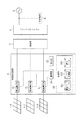
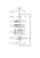
図1は、本発明の一実施形態に係る異常検出装置を備える太陽光発電システムの機能ブロック図である。太陽光発電システムは、複数の太陽電池ストリング1と、異常検出装置2と、接続箱3と、パワーコンディショナ4と、商用電力系統5と、負荷機器6と、を備える。図1では簡便のため、3つの太陽電池ストリング(1−1,1−2,1−3)を備えている様子を示す。以下において、各太陽電池ストリング1は同一環境下において発電量が概ね同一となるものとして説明する。
(Embodiment)
FIG. 1 is a functional block diagram of a photovoltaic power generation system including an abnormality detection device according to an embodiment of the present invention. The solar power generation system includes a plurality of
太陽電池ストリング1は、太陽光を利用して発電する複数の太陽電池モジュールを直列接続して出力電圧を上昇させたものであり、直流電流を出力する。また太陽電池ストリング1は、異常検出装置2に接続される。
The
異常検出装置2は、EMS(Energy Management System)装置等の電力制御装置であり、接続される太陽電池ストリング1の出力電流の異常を検出する。異常検出装置2は、複数の電流測定部21と、記憶部22と、通知部23と、制御部24と、を備える。
The
電流測定部21は、複数の太陽電池ストリング1にそれぞれ対応して接続され、対応する太陽電池ストリング1の発電した出力電流を測定する。
The
記憶部22は、測定データテーブル211と、システム初期値222と、照合データ223を記憶している。
The
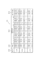
ここで図2を参照して測定データテーブル221について説明する。測定データテーブル221は、各太陽電池ストリング1の電流測定値及び電流測定値に係る全太陽電池ストリングの平均値を、所定の時刻毎に複数日にわたって蓄積したものであり、制御部24によってシステム初期値222を設定するのに用いられる。本実施形態において、測定データテーブル221は、測定日2211と、時刻2212と、電流測定値2213と、第1の平均値2214と、を含む。
Here, the measurement data table 221 will be described with reference to FIG. The measurement data table 221 is obtained by accumulating the measured current value of each
測定日2211は、太陽光発電システムを稼働した日所定の基準日を1日目として太陽電池ストリング1の出力電流を測定した日付を示す。以下において、基準日(又は基準時)は太陽光発電システムの稼働日(又は稼働時)であるものとして説明するが、例えば太陽光発電システムをリセットした日(又はリセット時)等とすることができる。図2においては簡便のため、測定日2211として「1日目」、「2日目」、及び「d日目」を示している。
The
時刻2212は、電流測定部21が出力電流の測定を行う所定の時刻を示す。ここで所定の時刻とは、一日のうち日の出ている時間帯から任意の時刻を複数選択したものである。例えば本実施形態においては、8時から17時まで1時間毎に測定する。図2においては簡便のため、「8:00(8時)」、「9:00(9時)」、及び「17:00(17時)」を示している。
電流測定値2213は、測定日2211及び時刻2212に対応付けられた各太陽電池ストリング1の電流測定値を示す。図2における電流測定値2213の値は、「S[ストリング番号]−[測定日]−[時刻]」で示している。
The measured
第1の平均値2214は、測定日2211及び時刻2212に対応付けられた電流測定値2213に係る全太陽電池ストリング1の平均値を示す。図2における第1の平均値2214の値は、「Ave−[測定日]−[時刻]」で示している。
The first
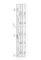
次に図3を参照してシステム初期値222について説明する。システム初期値222は、太陽光発電システムにおける所定の時刻毎の各太陽電池ストリング1の出力電流の基準値を示すものであり、制御部24によって太陽光発電システムの経時的な発電量の減少を検出するのに用いられる。本実施形態において、システム初期値222は、時刻2221と、電流最大値2222と、第2の平均値2223と、を含む。
Next, the system
時刻2221は、測定データテーブル221の時刻2212と対応する時刻を示す。
A
電流最大値2222は、時刻2221に対応付けられており、各太陽電池ストリング1について太陽光発電システムの稼働日から複数日分の電流測定値における最大値を示す。本実施形態において、電流最大値2222は、各太陽電池ストリング1について、測定データテーブル221の1日目からd日目までの電流測定値2213における最大値をそれぞれ抽出したものである。
The maximum
既に述べたように、太陽光発電システムは天候、日射量、季節、又は時間帯等によって発電量が異なる。複数日間における電流測定値には、例えば天候不順等の環境条件により発電量が低下している場合が含まれ得る。しかし、太陽光発電システムの出力電流の基準値であるシステム初期値222の決定においてこのような環境条件により低下した発電量を考慮すべきではない。また、太陽光発電システムの発電量は、その設置条件(例えば立地条件、周辺環境等)によって変動し得る。このため、太陽光発電システムの出力電流の基準値であるシステム初期値222を、例えば太陽電池モジュールの定格等に基づいて直ちに決定することはできない。従って、各太陽電池ストリング1について複数日分の電流測定値2213における最大値をそれぞれ抽出することにより、複数日間において最も環境による影響の少ない電流測定値、言い換えると複数日間において最も太陽光発電に理想的な環境における電流測定値をシステム初期値222とする。図3における電流最大値2222の値は、「S[ストリング番号]−0−[時刻]」で示している。
As already described, the power generation amount of the solar power generation system varies depending on the weather, the amount of solar radiation, the season, or the time zone. The current measurement values for a plurality of days may include a case where the power generation amount is reduced due to environmental conditions such as bad weather. However, in determining the system
第2の平均値2223は、時刻2221に対応付けられた電流最大値2222に係る全太陽電池ストリング1の平均値を示す。
The second
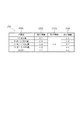
次に図4を参照して照合データ223について説明する。照合データ223は、予め記憶部22に記憶されており、制御部24によって太陽電池ストリング1の出力異常を判断するのに用いられる。本実施形態において、照合データ223は、時間帯2231と、第1の閾値2232と、第2の閾値2233と、第3の閾値2234と、を含む。照合データ223に含まれるこれらの情報の値は、太陽光発電システムの稼働後に操作者が変更可能に構成されてもよい。
Next, the
時間帯2231は、一日のうち日が出ている時間帯を任意に分割した複数の時間帯を示す。本実施形態においては、2時間ずつ5つの時間帯に分割している。
The
第1の閾値2232は、時間帯2231に対応付けられた0以上1以下の値であり、システム稼働後の経時変化による太陽電池ストリング1の出力電流の異常を検出するために制御部24によって用いられる。好適には第1の閾値2232は、日射量が多いと考えられる時間帯ほど高い値に設定される。例えば本実施形態においては、一日のうち日射量が最も多いと考えられる「11:00〜13:00未満(11時以降13時未満)」の時間帯で第1の閾値2232は「0.9」と高い値が設定されており、日射量が少ないと考えられる朝夕の「〜9:00未満(9時未満)」及び「15:00〜(15時以降)」の時間帯で第1の閾値2232は「0.7」と低い値が設定されている。
The
第2の閾値2233は、0以上1以下の値であり、太陽電池ストリング1に係る出力電流の測定時における天候不順を判断するために制御部24によって用いられる。本実施形態において、第2の閾値2233は、時間帯2231によらず一定の値(「0.3」)を設定しているが、時間帯2231毎に異なる値を設定してもよい。
The
第3の閾値2234は、時間帯2231に対応付けられた0以上1以下の値であり、システム稼働時の初期不良等による太陽電池ストリング1の出力電流の異常を検出するために制御部24によって用いられる。好適には第3の閾値2234は、日射量が多いと考えられる時間帯ほど高い値に設定される。例えば本実施形態においては、一日のうち日射量が最も多いと考えられる「11:00〜13:00未満」の時間帯で第3の閾値2234は「0.7」と高い値が設定されており、日射量が少ないと考えられる朝夕の「〜9:00未満」及び「15:00〜」の時間帯で第3の閾値2234は「0.5」と低い値が設定されている。
The
図1の説明に戻る。通知部23は、制御部24が太陽電池ストリング1の出力電流の異常の有無を判断した場合、判断結果を装置の操作者に通知する。通知部23は、例えば、スピーカ又は液晶ディスプレイ等による表示パネルとすることができる。LED等の発光素子による点滅等の報知にて代用してもよい。
Returning to the description of FIG. When the control unit 24 determines whether or not the output current of the
制御部24は、異常検出装置2全体の動作を制御する。また制御部24は、現在時刻を取得可能であり、太陽光発電システム稼働時からの経過時間を測定する。
The control unit 24 controls the operation of the entire
また制御部24は、測定データテーブル221の内容を更新して記憶部22に記憶させる。具体的には、制御部24は、太陽光発電システムの稼働後、所定の時刻毎に電流測定部21から各太陽電池ストリング1に対応する電流測定値を電流測定部21からそれぞれ取得する。続いて制御部24は、取得した複数の電流測定値に係る全太陽電池ストリング1の平均値である第1の平均値を算出する。続いて制御部24は、取得した複数の電流測定値及び算出した第1の平均値を、測定日2211及び時刻2212に対応付けて、それぞれ電流測定値2213及び第1の平均値2214として測定データテーブル221に蓄積して記憶部22に記憶させる。
Further, the control unit 24 updates the content of the measurement data table 221 and stores it in the
また制御部24は、測定データテーブル221に基づいてシステム初期値222を設定する。具体的には、制御部24は、各太陽電池ストリング1について所定の時刻毎に、測定データテーブル221に含まれる1日目から複数日分(例えば、d日分)の電流測定値2213における最大値である電流最大値をそれぞれ抽出する。続いて制御部24は、所定の時刻毎に、抽出した電流最大値に係る全太陽電池ストリング1の平均値である第2の平均値を算出する。そして制御部24は、各太陽電池ストリング1について所定の時刻毎に、抽出した電流最大値及び第2の平均値をそれぞれ電流最大値2222及び第2の平均値2223として、システム初期値222を設定し、記憶部22に記憶させる。
Further, the control unit 24 sets the system
また制御部24は、測定データテーブル221とシステム初期値222とに基づいて、照合データ223との照合によりシステム稼働後の経時変化による太陽電池ストリング1の出力電流の異常を検出する。具体的には、制御部24は、測定データテーブル221における最新の測定日2211(p日目)かつ最新の時刻2212(時刻t)に係る電流測定値2213(すなわち、「Sm−p−t」)及び第1の平均値2214(すなわち、「Ave−p−t」)を抽出する。続いて制御部24は、式(1)に示すように、各太陽電池ストリング1について、抽出した第1の平均値2214に対する電流測定位置2213の割合(すなわち、「Sm−p−t」/「Ave−p−t」)を、時刻tにおける第2の平均値2223に対する電流最大値2222の割合(すなわち、「Sm−0−t」/「Ave−0−t」)で除算した値であるAを算出する。
In addition, the control unit 24 detects an abnormality in the output current of the

続いて制御部24は、式(1)の算出結果Aを照合データ223と照合し、その算出結果Aが時刻tの属する時間帯2231に対応する第1の閾値2232以下であるか否かを判断する。そして制御部24は、算出結果Aが第1の閾値2232以下である場合、対応する太陽電池ストリング1の出力電流は異常であると判断する。一方、制御部24は、算出結果Aが第1の閾値2232よりも大きい場合、対応する太陽電池ストリング1の出力電流は正常であると判断する。
Subsequently, the control unit 24 collates the calculation result A of Expression (1) with the
好適には、制御部24は、電流測定値2213及び第1の平均値2214を抽出した後、式(2)に示すように、システム初期値222の時刻tにおける第2の平均値2223に対する抽出した第1の平均値2214の割合であるBの値を算出する。
Preferably, after extracting the
続いて制御部24は、式(2)の算出結果Bを照合データ223と照合し、その算出結果Bが第2の閾値2233以下であるか否かを判断する。そして制御部24は、算出結果Bが第2の閾値2233以下である場合、システム全体として発電量が少ないため、天候不順と判断して太陽電池ストリング1の出力異常に関する判断を行わない。一方、制御部24は、算出結果Bが第2の閾値2233よりも大きい場合、太陽電池ストリング1の出力異常検出動作を継続する。このようにすることで、天候不順等によりシステム全体の発電量が低下しているにもかかわらず、太陽電池ストリング1の出力電流が異常であると誤って判断することを防止できる。
Subsequently, the control unit 24 collates the calculation result B of Expression (2) with the
また制御部24は、システム稼働時(時刻u)の太陽電池ストリング1の初期不良を検出する。具体的には、制御部24は、時刻uにおいて複数の電流測定部21から各太陽電池ストリング1に対応する電流測定値をそれぞれ取得する。続いて制御部24は、取得した複数の電流測定値に係る第1の平均値を算出する。続いて制御部24は、式(3)に示すように、第1の平均値に対する電流測定値の割合であるCの値を算出する。
Moreover, the control part 24 detects the initial failure of the
続いて制御部24は、式(3)の算出結果Cを照合データ223と照合し、算出結果Cが、時刻uが属する時間帯2231に対応する第3の閾値2234以下であるか否かを判断する。例えば、時刻uが9時30分である場合、当該時刻が属する時間帯2231は「9:00〜11:00未満」であり、対応する第3の閾値2234は「0.6」である。そして制御部24は、算出結果Cが第3の閾値2234以下である場合、対応する太陽電池ストリング1の初期不良と判断する。
Subsequently, the control unit 24 collates the calculation result C of Expression (3) with the
接続箱3は、異常検出装置2を経由して複数の太陽電池ストリング1が並列に接続されており、直流電流を昇圧してパワーコンディショナ4に入力する。
In the
パワーコンディショナ4は、接続箱3から入力される直流電力を交流電力に変換する。またパワーコンディショナ4は、商用電力系統5に連系し、変換した交流電力及び商用電力系統5から供給された交流電力を負荷機器6に供給する。またパワーコンディショナ4は、変換した交流電力を電力会社に売電可能である。
The
図5は、本発明の一実施形態に係る測定データテーブル221の更新処理を示すフローチャート図である。はじめに制御部24は、太陽光発電システムの稼働後に、太陽電池ストリング1の出力電流を測定する日付として、pの値を1に設定する(ステップS100)。図5の説明において、測定日をp日目と記載する。
FIG. 5 is a flowchart showing update processing of the measurement data table 221 according to an embodiment of the present invention. First, the control unit 24 sets the value of p to 1 as a date for measuring the output current of the
続いて制御部24は、現在時刻が所定の時刻のいずれかに該当するか否かを判断する(ステップS101)。ここで所定の時刻とは、一日のうち日の出ている時間帯から任意の時刻を複数選択したものであって、図2における測定データテーブル221の時刻2212に対応する。所定の時刻のいずれかに該当すると判断した場合、ステップS102に進む。一方、所定の時刻のいずれにも該当しないと判断した場合、ステップS101を繰り返して所定の時刻のいずれかに該当するまで待つ。
Subsequently, the control unit 24 determines whether or not the current time corresponds to any one of predetermined times (step S101). Here, the predetermined time is a time when a plurality of arbitrary times are selected from the sunrise time zone of the day, and corresponds to the
続いて制御部24は、所定の時刻のうちいずれかの時刻において複数の電流測定部21から各太陽電池ストリング1に対応する電流測定値をそれぞれ取得する(ステップS102)。
Subsequently, the control unit 24 acquires current measurement values corresponding to the
続いて制御部24は、取得した複数の電流測定値に係る第1の平均値を算出する(ステップS103)。 Subsequently, the control unit 24 calculates a first average value related to the acquired plurality of current measurement values (step S103).
続いて制御部24は、取得した複数の電流測定値及び算出した第1の平均値を、p日目である測定日2211及び測定時刻と同一の時刻2212に対応付けて、それぞれ電流測定値2213及び第1の平均値2214として測定データテーブル221に蓄積し、記憶部22に記憶させる(ステップS104)。
Subsequently, the control unit 24 associates the acquired plurality of current measurement values and the calculated first average value with the
続いて制御部24は、システム稼働時から一日経過したか否かを判断する(ステップS105)。一日経過したと判断した場合、ステップS106に進む。一方、一日経過していないと判断した場合、ステップS101に戻る。 Subsequently, the control unit 24 determines whether one day has elapsed since the system was operated (step S105). If it is determined that one day has passed, the process proceeds to step S106. On the other hand, if it is determined that one day has not elapsed, the process returns to step S101.
ステップS105においてシステム稼働時から一日経過したと判断した場合、制御部24は、pの値をインクリメントして(ステップS106)、ステップS101に戻る。 If it is determined in step S105 that one day has elapsed since the system was activated, the control unit 24 increments the value of p (step S106) and returns to step S101.
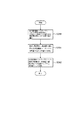
図6は、本発明の一実施形態に係るシステム初期値222の設定処理を示すフローチャート図である。はじめに制御部24は、各太陽電池ストリング1について所定の時刻毎に、測定データテーブル221に含まれる1日目から複数日分(例えば、d日分)の電流測定値2213における最大値である電流最大値をそれぞれ抽出する(ステップS200)。
FIG. 6 is a flowchart showing a system
続いて制御部24は、所定の時刻毎に、抽出した電流最大値に係る全太陽電池ストリング1の平均値(以下、第2の平均値)を算出する(ステップS201)。
Then, the control part 24 calculates the average value (henceforth a 2nd average value) of all the
続いて制御部24は、各太陽電池ストリング1について所定の時刻毎に、抽出した電流最大値及び第2の平均値をそれぞれ電流最大値2222及び第2の平均値2223として、システム初期値222を設定し、記憶部22に記憶させる(ステップS202)。
Subsequently, the control unit 24 sets the system
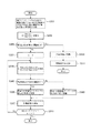
図7は、本発明の一実施形態に係るシステム稼働後の経時変化による太陽電池ストリング1の異常検出処理を示すフローチャート図である。経時変化による異常検出処理の前提として、図6に示す処理によりシステム初期値222が設定されているものとする。はじめに制御部24は、測定データテーブル221における最新の測定日2211(p日目)かつ最新の時刻2212(時刻t)に係る電流測定値2213及び第1の平均値2214を抽出する(ステップS300)。
FIG. 7 is a flowchart showing an abnormality detection process of the
続いて制御部24は、式(2)に示すように、システム初期値222の時刻tにおける第2の平均値2223に対する抽出した第1の平均値2214の割合であるBの値を算出する(ステップS301)。
Subsequently, as shown in Expression (2), the control unit 24 calculates a value B, which is a ratio of the extracted first
続いて制御部24は、ステップS301の算出結果Bを照合データ223と照合し、算出結果Bが第2の閾値2233以下であるか否かを判断する(ステップS302)。算出結果Bが第2の閾値2233よりも大きいと判断した場合、ステップS303に進む。一方、算出結果Bが第2の閾値2233以下であると判断した場合、ステップS311に進む。
Subsequently, the control unit 24 collates the calculation result B in step S301 with the
ステップS302において、算出結果Bが第2の閾値2233よりも大きいと判断した場合、制御部24は、複数の太陽電池ストリング1に係る番号として、mの値を1に設定する(ステップS303)。図7の説明において、太陽光発電システムはn個の太陽電池ストリング1を備えるものとし、各太陽電池ストリング1を第mの太陽電池ストリング1−mと記載する。
In step S302, when it is determined that the calculation result B is larger than the
続いて制御部24は、(1)式に示すように、第mの太陽電池ストリング1−mについて、抽出した第1の平均値2214に対する電流測定位置2213の割合を、時刻tにおける第2の平均値2223に対する電流最大値2222の割合で除算した値であるAを算出する(ステップS304)。
Subsequently, as shown in the equation (1), the control unit 24 calculates the ratio of the
続いて制御部24は、ステップS304の算出結果Aを照合データ223と照合し、算出結果Aが時刻tの属する時間帯2231に対応する第1の閾値2232以下であるか否かを判断する(ステップS305)。算出結果Aが第1の閾値2232以下であると判断した場合、ステップS306に進む。一方、算出結果Aが第1の閾値2232よりも大きいと判断した場合、ステップS309に進む。
Subsequently, the control unit 24 collates the calculation result A in step S304 with the
ステップS305において、算出結果Aが第1の閾値2232以下であると判断した場合、制御部24は、第mの太陽電池ストリング1−mの出力電流は異常であると判断する(ステップS306)。又は、ステップS305において、算出結果Aが第1の閾値2232よりも大きいと判断した場合、制御部24は、第mの太陽電池ストリング1−mの出力電流は正常であると判断する(ステップS309)。
In step S305, when it is determined that the calculation result A is equal to or less than the
続いて通知部23は、制御部24による判断結果を操作者に通知する(ステップS307)。
Subsequently, the
続いて制御部24は、mの値をインクリメントし、mの値がnよりも大きいか否かを判断する(ステップS308)。mの値がnよりも大きいと判断した場合、処理を終了する。一方、mの値がn以下であると判断した場合、ステップS304に戻る。 Subsequently, the control unit 24 increments the value of m and determines whether the value of m is larger than n (step S308). If it is determined that the value of m is greater than n, the process ends. On the other hand, if it is determined that the value of m is less than or equal to n, the process returns to step S304.
一方、ステップS302において、算出結果Bが第2の閾値2233以下であると判断した場合、制御部24は、システム全体として発電量が少ないため、天候不順と判断する(ステップS310)。この場合、制御部24は、太陽電池ストリング1の出力異常に関する判断を行わない。
On the other hand, if it is determined in step S302 that the calculation result B is equal to or less than the
続いて通知部23は、制御部24による判断結果を操作者に通知して(ステップS311)、処理を終了する。
Subsequently, the
このように本実施形態によれば、太陽光発電システムの稼働日から複数日分の太陽電池ストリング1の電流測定値に基づいて太陽光発電システム稼働当初における出力電流の基準値であるシステム初期値222を設定し、現在の出力電流とシステム初期値222とに基づいて太陽電池ストリング1の出力異常を検出することにより、太陽光発電システムの発電量が妥当かどうかを容易に判断することができる。また、各太陽電池ストリング1について出力電流の異常をそれぞれ検出するため、異常個所の特定が容易である。また、異常個所の特定が容易になることにより、迅速なメンテナンス対処を行うことができ、発電量が減少したまま運用されてしまう期間を抑制することができる。
As described above, according to the present embodiment, the system initial value that is the reference value of the output current at the beginning of the operation of the solar power generation system based on the current measurement values of the
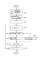
図8は、本発明の一実施形態に係るシステム稼働時の太陽電池ストリング1の初期不良検出処理を示すフローチャート図である。はじめに制御部24は、太陽光発電システムの稼働時(時刻u)に、複数の電流測定部21から各太陽電池ストリング1に対応する電流測定値をそれぞれ取得する(ステップS400)。
FIG. 8 is a flowchart showing an initial failure detection process for the
続いて制御部24は、取得した複数の電流測定値に基づいて第1の平均値を算出する(ステップS401)。 Subsequently, the control unit 24 calculates a first average value based on the acquired plurality of current measurement values (step S401).
続いて制御部24は、複数の太陽電池ストリング1に係る番号として、mの値を1に設定する(ステップS402)。図8の説明において、太陽光発電システムはn個の太陽電池ストリング1を備えるものとし、各太陽電池ストリング1を第mの太陽電池ストリング1−mと記載する。
Then, the control part 24 sets the value of m as 1 as the number which concerns on the some solar cell string 1 (step S402). In the description of FIG. 8, the solar power generation system is assumed to include n
続いて制御部24は、式(3)に示すように、時刻tにおける第1の平均値に対する第mの太陽電池ストリング1−mに係る電流測定値の割合であるCの値を算出する(ステップS403)。 Subsequently, as shown in Expression (3), the control unit 24 calculates a value C, which is a ratio of the current measurement value related to the m-th solar cell string 1-m with respect to the first average value at time t ( Step S403).
続いて制御部24は、ステップS403の算出結果Cを照合データ223と照合し、算出結果Cが、時刻uが属する時間帯2231に対応する第3の閾値2234以下であるか否かを判断する(ステップS404)。算出結果Cが第3の閾値2234以下である場合、ステップS405に進む。一方、算出結果Cが第3の閾値2234よりも大きい場合、ステップS408に進む。
Subsequently, the control unit 24 collates the calculation result C in step S403 with the
ステップS404において算出結果Cが第3の閾値2234以下であると判断した場合、制御部24は、第mの太陽電池ストリング1−mの初期不良と判断する(ステップS405)。又は、ステップS404において算出結果Cが第3の閾値2234よりも大きいと判断した場合、制御部24は、第mの太陽電池ストリング1−mの出力は正常であると判断する(ステップS408)。
When determining that the calculation result C is equal to or less than the
続いて通知部23は、制御部24による判断結果を操作者に通知する(ステップS406)。
Subsequently, the
続いて制御部24は、mの値をインクリメントし、mの値がnよりも大きいか否かを判断する(ステップS407)。mの値がnよりも大きい場合、処理を終了する。一方、mの値がn以下である場合、ステップS403に戻る。 Subsequently, the control unit 24 increments the value of m, and determines whether or not the value of m is larger than n (step S407). If the value of m is larger than n, the process is terminated. On the other hand, when the value of m is n or less, the process returns to step S403.
このように、太陽光システム稼働時に各太陽電池ストリング1の出力電流を測定し、電流測定値と電流測定値に係る全太陽電池ストリング1の平均値と比較することにより、太陽光発電システム稼働時の太陽電池ストリング1の初期不良を検出することができる。
Thus, by measuring the output current of each
(変形例)
次に、本発明の実施の形態の変形例について説明する。変形例に係る異常検出装置2は、上述の実施の形態に係る構成において、概略として太陽電池ストリング1の出力異常の原因を判断して操作者に通知する。
(Modification)
Next, a modification of the embodiment of the present invention will be described. In the configuration according to the above-described embodiment, the
変形例に係る異常検出装置2の制御部24は、各太陽電池ストリング1について太陽電池ストリング1の出力異常に係る判断結果を、電流測定値2213とともに測定データテーブル221に蓄積して記憶部22に記憶させる。そして制御部24は、出力異常の発生状況に基づいて、出力異常の発生原因を判断する。
The control unit 24 of the
例えば、変形例に係る異常検出装置2の制御部24は、1つの太陽電池ストリング1において連続する複数日にわたって特定の時間帯において出力異常が発生している場合、当該時間帯はその太陽電池ストリング1に対する日射が遮られて日陰になっていると判断する。また例えば、変形例に係る制御部24は、1つの太陽電池ストリング1において連続する複数日にわたって一日の全ての時間帯において出力異常が発生している場合、その太陽電池ストリング1の故障と判断する。そして異常検出装置2の通知部23は、制御部24が判断した出力異常の発生原因を操作者に通知する。
For example, the control unit 24 of the
このように変形例によれば、太陽電池ストリング1の出力異常の発生状況に基づいて出力異常の発生原因を特定することができる。また、出力異常の発生原因を操作者に通知することにより、発生原因に応じて適切なメンテナンス対処を行うことができ、発電量が減少しているにもかかわらずそのまま運用されてしまう期間を更に抑制することができる。
As described above, according to the modification, the cause of the output abnormality can be specified based on the state of occurrence of the output abnormality of the
本発明を諸図面や実施例に基づき説明してきたが、当業者であれば本開示に基づき種々の変形や修正を行うことが容易であることに注意されたい。例えば、各手段、各ステップ等に含まれる機能等は論理的に矛盾しないように再配置可能であり、複数の手段やステップ等を1つに組み合わせたり、或いは分割したりすることが可能である。 Although the present invention has been described based on the drawings and examples, it should be noted that those skilled in the art can easily make various modifications and corrections based on the present disclosure. For example, the functions included in each means, each step, etc. can be rearranged so that there is no logical contradiction, and a plurality of means, steps, etc. can be combined or divided into one. .
例えば、本発明に係る異常検出装置2を、複数の太陽電池ストリング1を並列して接続可能なマルチストリング構成のパワーコンディショナ、又は接続箱等の他の装置に統合することが考えられる。
For example, it is conceivable to integrate the
また例えば、本発明に係る異常検出装置2を家庭用に展開する場合、HEMS(Home Energy Management System)装置に統合することが考えられる。
Further, for example, when the
1 太陽電池ストリング
2 異常検出装置
3 接続箱
4 パワーコンディショナ
5 商用電力系統
6 負荷機器
21 電流測定部
22 記憶部
23 通知部
24 制御部
221 測定データテーブル
222 システム初期値
223 照合データ
2211 測定日
2212 時刻
2213 電流測定値
2214 第1の平均値
2221 時刻
2222 電流最大値
2223 第2の平均値
2231 時間帯
2232 第1の閾値
2233 第2の閾値
2234 第3の閾値
DESCRIPTION OF
Claims (5)
Priority Applications (1)
| Application Number | Priority Date | Filing Date | Title |
|---|---|---|---|
| JP2013092989A JP6087200B2 (en) | 2013-04-25 | 2013-04-25 | Abnormality detection device for solar power generation system, abnormality detection method, and solar power generation system |
Applications Claiming Priority (1)
| Application Number | Priority Date | Filing Date | Title |
|---|---|---|---|
| JP2013092989A JP6087200B2 (en) | 2013-04-25 | 2013-04-25 | Abnormality detection device for solar power generation system, abnormality detection method, and solar power generation system |
Publications (2)
| Publication Number | Publication Date |
|---|---|
| JP2014216501A JP2014216501A (en) | 2014-11-17 |
| JP6087200B2 true JP6087200B2 (en) | 2017-03-01 |
Family
ID=51941984
Family Applications (1)
| Application Number | Title | Priority Date | Filing Date |
|---|---|---|---|
| JP2013092989A Active JP6087200B2 (en) | 2013-04-25 | 2013-04-25 | Abnormality detection device for solar power generation system, abnormality detection method, and solar power generation system |
Country Status (1)
| Country | Link |
|---|---|
| JP (1) | JP6087200B2 (en) |
Families Citing this family (9)
| Publication number | Priority date | Publication date | Assignee | Title |
|---|---|---|---|---|
| JP6278912B2 (en) * | 2015-02-10 | 2018-02-14 | 株式会社日立製作所 | Photovoltaic power generation system and fault diagnosis method thereof |
| JP6597425B2 (en) * | 2016-03-15 | 2019-10-30 | オムロン株式会社 | FACTOR ESTIMATION DEVICE, FACTOR ESTIMATION DEVICE CONTROL METHOD, CONTROL PROGRAM, AND RECORDING MEDIUM |
| JP6093465B1 (en) * | 2016-03-30 | 2017-03-08 | 株式会社ラプラス・システム | Power generation diagnosis method and power generation diagnosis apparatus for solar power generation system |
| KR101870346B1 (en) * | 2016-09-30 | 2018-06-22 | 헵시바주식회사 | Fault diagnosis method of multi string solar cells connected to multi string solar inverter |
| CN106597151B (en) * | 2016-12-02 | 2021-01-15 | 中国电力科学研究院有限公司 | Photovoltaic power station switched inverter tracking efficiency testing method and system |
| WO2019163414A1 (en) * | 2018-02-20 | 2019-08-29 | 太陽誘電株式会社 | Solar power generation failure determination device, solar power generation failure determination method, and program |
| WO2019163413A1 (en) * | 2018-02-20 | 2019-08-29 | 太陽誘電株式会社 | Photovoltaic power generation failure diagnosis device, photovoltaic power generation failure diagnosis method, and program |
| JP6664027B1 (en) * | 2019-08-20 | 2020-03-13 | 株式会社ミライト | Deterioration detection method, degradation detection system, and degradation detection device for solar cell string |
| JP6698234B1 (en) * | 2020-02-17 | 2020-05-27 | 株式会社ミライト | Degradation detection method for solar cell string, degradation detection system, and degradation detection device |
Family Cites Families (5)
| Publication number | Priority date | Publication date | Assignee | Title |
|---|---|---|---|---|
| JP2874156B2 (en) * | 1994-04-13 | 1999-03-24 | キヤノン株式会社 | Power generation system |
| JP2005340464A (en) * | 2004-05-26 | 2005-12-08 | Sharp Corp | Solar cell array diagnostic system and solar light generating system using thereof |
| JP2010287608A (en) * | 2009-06-09 | 2010-12-24 | Kowa Denki Sangyo Kk | Apparatus, system and method for detecting degradation of photovoltaic power generator |
| US20110088743A1 (en) * | 2009-10-15 | 2011-04-21 | Yuhao Luo | Method to manage a photovoltaic system |
| JP5584622B2 (en) * | 2010-02-19 | 2014-09-03 | オーナンバ株式会社 | Fault detection method for photovoltaic system |
-
2013
- 2013-04-25 JP JP2013092989A patent/JP6087200B2/en active Active
Also Published As
| Publication number | Publication date |
|---|---|
| JP2014216501A (en) | 2014-11-17 |
Similar Documents
| Publication | Publication Date | Title |
|---|---|---|
| JP6087200B2 (en) | Abnormality detection device for solar power generation system, abnormality detection method, and solar power generation system | |
| CN106688176B (en) | Photovoltaic power generation system with fault diagnosis device and fault diagnosis method thereof | |
| US8482309B2 (en) | Failure detecting method for a solar power generation system | |
| CN102576047B (en) | For identifying the method and apparatus of the fault in photovoltaic apparatus | |
| JP6096099B2 (en) | Photovoltaic power generation system and solar cell module diagnostic method | |
| US8290745B2 (en) | Systems and methods for identifying faulty sensors within a power generation system | |
| WO2013136850A1 (en) | Information processing apparatus, abnormality detecting method, program, and solar power generation system | |
| JP2011134862A (en) | Photovoltaic power generation system | |
| JP2005340464A (en) | Solar cell array diagnostic system and solar light generating system using thereof | |
| JP2011216811A (en) | Solar cell abnormality diagnosis system, solar cell abnormality diagnosis apparatus and solar cell abnormality diagnosis method | |
| JP6093465B1 (en) | Power generation diagnosis method and power generation diagnosis apparatus for solar power generation system | |
| JP2010287608A (en) | Apparatus, system and method for detecting degradation of photovoltaic power generator | |
| JP6114016B2 (en) | Power conditioner control method and power conditioner | |
| JP2015198485A (en) | Abnormality detection device, abnormality detection system, and abnormality detection method | |
| WO2016166991A1 (en) | Diagnostic system for photovoltaic power generation equipment, and program | |
| JP2011077477A (en) | Monitor | |
| JP7289995B2 (en) | Method and apparatus for recognizing operating state of photovoltaic string and storage medium | |
| US20190140589A1 (en) | Computer device and method for determining whether a solar energy panel array is abnormal | |
| JP2016027771A (en) | Failure detection device, failure detection method and failure detection system | |
| JP6823499B2 (en) | Information processing device and control method of information processing device | |
| JP2015099858A (en) | Abnormality detection device | |
| JPWO2021117127A1 (en) | Power generation amount prediction device | |
| JP2015231280A (en) | Monitoring device for solar battery and monitoring system for solar battery | |
| JP2016220494A (en) | Support system for power generation amount estimation learning in photovoltaic power generation | |
| JP2015089145A (en) | Power conditioner |
Legal Events
| Date | Code | Title | Description |
|---|---|---|---|
| A621 | Written request for application examination |
Free format text: JAPANESE INTERMEDIATE CODE: A621 Effective date: 20151116 |
|
| A977 | Report on retrieval |
Free format text: JAPANESE INTERMEDIATE CODE: A971007 Effective date: 20160729 |
|
| A131 | Notification of reasons for refusal |
Free format text: JAPANESE INTERMEDIATE CODE: A131 Effective date: 20160913 |
|
| A521 | Request for written amendment filed |
Free format text: JAPANESE INTERMEDIATE CODE: A523 Effective date: 20161104 |
|
| TRDD | Decision of grant or rejection written | ||
| A01 | Written decision to grant a patent or to grant a registration (utility model) |
Free format text: JAPANESE INTERMEDIATE CODE: A01 Effective date: 20170110 |
|
| A61 | First payment of annual fees (during grant procedure) |
Free format text: JAPANESE INTERMEDIATE CODE: A61 Effective date: 20170201 |
|
| R150 | Certificate of patent or registration of utility model |
Ref document number: 6087200 Country of ref document: JP Free format text: JAPANESE INTERMEDIATE CODE: R150 |