JP6087019B2 - Window assembly with a transparent region having a property enhancing slit - Google Patents
Window assembly with a transparent region having a property enhancing slit Download PDFInfo
- Publication number
- JP6087019B2 JP6087019B2 JP2016500199A JP2016500199A JP6087019B2 JP 6087019 B2 JP6087019 B2 JP 6087019B2 JP 2016500199 A JP2016500199 A JP 2016500199A JP 2016500199 A JP2016500199 A JP 2016500199A JP 6087019 B2 JP6087019 B2 JP 6087019B2
- Authority
- JP
- Japan
- Prior art keywords
- region
- transparent layer
- substrate
- window assembly
- regions
- Prior art date
- Legal status (The legal status is an assumption and is not a legal conclusion. Google has not performed a legal analysis and makes no representation as to the accuracy of the status listed.)
- Active
Links
- 230000002708 enhancing effect Effects 0.000 title description 6
- 239000000758 substrate Substances 0.000 claims description 97
- 238000005192 partition Methods 0.000 claims description 16
- 230000005855 radiation Effects 0.000 claims description 16
- 150000002736 metal compounds Chemical class 0.000 claims description 8
- 238000000576 coating method Methods 0.000 description 12
- 230000002093 peripheral effect Effects 0.000 description 10
- 239000011248 coating agent Substances 0.000 description 7
- 230000005540 biological transmission Effects 0.000 description 6
- 239000000463 material Substances 0.000 description 6
- 239000011521 glass Substances 0.000 description 5
- 229910044991 metal oxide Inorganic materials 0.000 description 4
- 150000004706 metal oxides Chemical class 0.000 description 4
- 238000000034 method Methods 0.000 description 4
- 239000004020 conductor Substances 0.000 description 3
- 238000012545 processing Methods 0.000 description 3
- 238000010257 thawing Methods 0.000 description 3
- 239000000654 additive Substances 0.000 description 2
- 230000000996 additive effect Effects 0.000 description 2
- 238000000429 assembly Methods 0.000 description 2
- 230000000712 assembly Effects 0.000 description 2
- 230000008901 benefit Effects 0.000 description 2
- 238000012217 deletion Methods 0.000 description 2
- 230000037430 deletion Effects 0.000 description 2
- 238000005498 polishing Methods 0.000 description 2
- 229920002037 poly(vinyl butyral) polymer Polymers 0.000 description 2
- NDVLTYZPCACLMA-UHFFFAOYSA-N silver oxide Chemical compound [O-2].[Ag+].[Ag+] NDVLTYZPCACLMA-UHFFFAOYSA-N 0.000 description 2
- 239000000126 substance Substances 0.000 description 2
- 238000002834 transmittance Methods 0.000 description 2
- PXGOKWXKJXAPGV-UHFFFAOYSA-N Fluorine Chemical compound FF PXGOKWXKJXAPGV-UHFFFAOYSA-N 0.000 description 1
- 230000002411 adverse Effects 0.000 description 1
- 230000008859 change Effects 0.000 description 1
- 238000005229 chemical vapour deposition Methods 0.000 description 1
- 238000013461 design Methods 0.000 description 1
- 239000003989 dielectric material Substances 0.000 description 1
- 230000007613 environmental effect Effects 0.000 description 1
- 229910052731 fluorine Inorganic materials 0.000 description 1
- 239000011737 fluorine Substances 0.000 description 1
- 239000003365 glass fiber Substances 0.000 description 1
- 238000010438 heat treatment Methods 0.000 description 1
- AMGQUBHHOARCQH-UHFFFAOYSA-N indium;oxotin Chemical compound [In].[Sn]=O AMGQUBHHOARCQH-UHFFFAOYSA-N 0.000 description 1
- 239000012212 insulator Substances 0.000 description 1
- 238000001755 magnetron sputter deposition Methods 0.000 description 1
- 230000000873 masking effect Effects 0.000 description 1
- 229910052751 metal Inorganic materials 0.000 description 1
- 239000002184 metal Substances 0.000 description 1
- 238000012986 modification Methods 0.000 description 1
- 230000004048 modification Effects 0.000 description 1
- 150000004767 nitrides Chemical class 0.000 description 1
- 239000004033 plastic Substances 0.000 description 1
- 229920003023 plastic Polymers 0.000 description 1
- 229920000642 polymer Polymers 0.000 description 1
- 230000008569 process Effects 0.000 description 1
- 230000009467 reduction Effects 0.000 description 1
- 229910001923 silver oxide Inorganic materials 0.000 description 1
- 239000005361 soda-lime glass Substances 0.000 description 1
- 238000005118 spray pyrolysis Methods 0.000 description 1
- 229920005992 thermoplastic resin Polymers 0.000 description 1
- XOLBLPGZBRYERU-UHFFFAOYSA-N tin dioxide Chemical compound O=[Sn]=O XOLBLPGZBRYERU-UHFFFAOYSA-N 0.000 description 1
- 229910001887 tin oxide Inorganic materials 0.000 description 1
- 238000013519 translation Methods 0.000 description 1
- 239000012780 transparent material Substances 0.000 description 1
- 238000007740 vapor deposition Methods 0.000 description 1
- 230000000007 visual effect Effects 0.000 description 1
Images


Classifications
-
- H—ELECTRICITY
- H01—ELECTRIC ELEMENTS
- H01Q—ANTENNAS, i.e. RADIO AERIALS
- H01Q1/00—Details of, or arrangements associated with, antennas
- H01Q1/27—Adaptation for use in or on movable bodies
- H01Q1/32—Adaptation for use in or on road or rail vehicles
- H01Q1/325—Adaptation for use in or on road or rail vehicles characterised by the location of the antenna on the vehicle
- H01Q1/3291—Adaptation for use in or on road or rail vehicles characterised by the location of the antenna on the vehicle mounted in or on other locations inside the vehicle or vehicle body
-
- B—PERFORMING OPERATIONS; TRANSPORTING
- B32—LAYERED PRODUCTS
- B32B—LAYERED PRODUCTS, i.e. PRODUCTS BUILT-UP OF STRATA OF FLAT OR NON-FLAT, e.g. CELLULAR OR HONEYCOMB, FORM
- B32B17/00—Layered products essentially comprising sheet glass, or glass, slag, or like fibres
- B32B17/06—Layered products essentially comprising sheet glass, or glass, slag, or like fibres comprising glass as the main or only constituent of a layer, next to another layer of a specific material
- B32B17/10—Layered products essentially comprising sheet glass, or glass, slag, or like fibres comprising glass as the main or only constituent of a layer, next to another layer of a specific material of synthetic resin
- B32B17/10005—Layered products essentially comprising sheet glass, or glass, slag, or like fibres comprising glass as the main or only constituent of a layer, next to another layer of a specific material of synthetic resin laminated safety glass or glazing
- B32B17/10009—Layered products essentially comprising sheet glass, or glass, slag, or like fibres comprising glass as the main or only constituent of a layer, next to another layer of a specific material of synthetic resin laminated safety glass or glazing characterized by the number, the constitution or treatment of glass sheets
- B32B17/10036—Layered products essentially comprising sheet glass, or glass, slag, or like fibres comprising glass as the main or only constituent of a layer, next to another layer of a specific material of synthetic resin laminated safety glass or glazing characterized by the number, the constitution or treatment of glass sheets comprising two outer glass sheets
-
- B—PERFORMING OPERATIONS; TRANSPORTING
- B32—LAYERED PRODUCTS
- B32B—LAYERED PRODUCTS, i.e. PRODUCTS BUILT-UP OF STRATA OF FLAT OR NON-FLAT, e.g. CELLULAR OR HONEYCOMB, FORM
- B32B17/00—Layered products essentially comprising sheet glass, or glass, slag, or like fibres
- B32B17/06—Layered products essentially comprising sheet glass, or glass, slag, or like fibres comprising glass as the main or only constituent of a layer, next to another layer of a specific material
- B32B17/10—Layered products essentially comprising sheet glass, or glass, slag, or like fibres comprising glass as the main or only constituent of a layer, next to another layer of a specific material of synthetic resin
- B32B17/10005—Layered products essentially comprising sheet glass, or glass, slag, or like fibres comprising glass as the main or only constituent of a layer, next to another layer of a specific material of synthetic resin laminated safety glass or glazing
- B32B17/10165—Functional features of the laminated safety glass or glazing
- B32B17/10174—Coatings of a metallic or dielectric material on a constituent layer of glass or polymer
- B32B17/10183—Coatings of a metallic or dielectric material on a constituent layer of glass or polymer being not continuous, e.g. in edge regions
- B32B17/10192—Coatings of a metallic or dielectric material on a constituent layer of glass or polymer being not continuous, e.g. in edge regions patterned in the form of columns or grids
-
- B—PERFORMING OPERATIONS; TRANSPORTING
- B32—LAYERED PRODUCTS
- B32B—LAYERED PRODUCTS, i.e. PRODUCTS BUILT-UP OF STRATA OF FLAT OR NON-FLAT, e.g. CELLULAR OR HONEYCOMB, FORM
- B32B17/00—Layered products essentially comprising sheet glass, or glass, slag, or like fibres
- B32B17/06—Layered products essentially comprising sheet glass, or glass, slag, or like fibres comprising glass as the main or only constituent of a layer, next to another layer of a specific material
- B32B17/10—Layered products essentially comprising sheet glass, or glass, slag, or like fibres comprising glass as the main or only constituent of a layer, next to another layer of a specific material of synthetic resin
- B32B17/10005—Layered products essentially comprising sheet glass, or glass, slag, or like fibres comprising glass as the main or only constituent of a layer, next to another layer of a specific material of synthetic resin laminated safety glass or glazing
- B32B17/10165—Functional features of the laminated safety glass or glazing
- B32B17/10174—Coatings of a metallic or dielectric material on a constituent layer of glass or polymer
- B32B17/10201—Dielectric coatings
- B32B17/10211—Doped dielectric layer, electrically conductive, e.g. SnO2:F
-
- B—PERFORMING OPERATIONS; TRANSPORTING
- B32—LAYERED PRODUCTS
- B32B—LAYERED PRODUCTS, i.e. PRODUCTS BUILT-UP OF STRATA OF FLAT OR NON-FLAT, e.g. CELLULAR OR HONEYCOMB, FORM
- B32B17/00—Layered products essentially comprising sheet glass, or glass, slag, or like fibres
- B32B17/06—Layered products essentially comprising sheet glass, or glass, slag, or like fibres comprising glass as the main or only constituent of a layer, next to another layer of a specific material
- B32B17/10—Layered products essentially comprising sheet glass, or glass, slag, or like fibres comprising glass as the main or only constituent of a layer, next to another layer of a specific material of synthetic resin
- B32B17/10005—Layered products essentially comprising sheet glass, or glass, slag, or like fibres comprising glass as the main or only constituent of a layer, next to another layer of a specific material of synthetic resin laminated safety glass or glazing
- B32B17/1055—Layered products essentially comprising sheet glass, or glass, slag, or like fibres comprising glass as the main or only constituent of a layer, next to another layer of a specific material of synthetic resin laminated safety glass or glazing characterized by the resin layer, i.e. interlayer
- B32B17/10761—Layered products essentially comprising sheet glass, or glass, slag, or like fibres comprising glass as the main or only constituent of a layer, next to another layer of a specific material of synthetic resin laminated safety glass or glazing characterized by the resin layer, i.e. interlayer containing vinyl acetal
-
- B—PERFORMING OPERATIONS; TRANSPORTING
- B60—VEHICLES IN GENERAL
- B60J—WINDOWS, WINDSCREENS, NON-FIXED ROOFS, DOORS, OR SIMILAR DEVICES FOR VEHICLES; REMOVABLE EXTERNAL PROTECTIVE COVERINGS SPECIALLY ADAPTED FOR VEHICLES
- B60J1/00—Windows; Windscreens; Accessories therefor
- B60J1/20—Accessories, e.g. wind deflectors, blinds
-
- G—PHYSICS
- G02—OPTICS
- G02B—OPTICAL ELEMENTS, SYSTEMS OR APPARATUS
- G02B5/00—Optical elements other than lenses
- G02B5/20—Filters
- G02B5/208—Filters for use with infrared or ultraviolet radiation, e.g. for separating visible light from infrared and/or ultraviolet radiation
-
- H—ELECTRICITY
- H01—ELECTRIC ELEMENTS
- H01Q—ANTENNAS, i.e. RADIO AERIALS
- H01Q1/00—Details of, or arrangements associated with, antennas
- H01Q1/12—Supports; Mounting means
- H01Q1/1271—Supports; Mounting means for mounting on windscreens
-
- H—ELECTRICITY
- H01—ELECTRIC ELEMENTS
- H01Q—ANTENNAS, i.e. RADIO AERIALS
- H01Q1/00—Details of, or arrangements associated with, antennas
- H01Q1/27—Adaptation for use in or on movable bodies
- H01Q1/32—Adaptation for use in or on road or rail vehicles
- H01Q1/325—Adaptation for use in or on road or rail vehicles characterised by the location of the antenna on the vehicle
-
- H—ELECTRICITY
- H01—ELECTRIC ELEMENTS
- H01Q—ANTENNAS, i.e. RADIO AERIALS
- H01Q21/00—Antenna arrays or systems
- H01Q21/28—Combinations of substantially independent non-interacting antenna units or systems
-
- H—ELECTRICITY
- H01—ELECTRIC ELEMENTS
- H01Q—ANTENNAS, i.e. RADIO AERIALS
- H01Q5/00—Arrangements for simultaneous operation of antennas on two or more different wavebands, e.g. dual-band or multi-band arrangements
- H01Q5/30—Arrangements for providing operation on different wavebands
- H01Q5/307—Individual or coupled radiating elements, each element being fed in an unspecified way
- H01Q5/342—Individual or coupled radiating elements, each element being fed in an unspecified way for different propagation modes
- H01Q5/357—Individual or coupled radiating elements, each element being fed in an unspecified way for different propagation modes using a single feed point
- H01Q5/364—Creating multiple current paths
-
- H—ELECTRICITY
- H01—ELECTRIC ELEMENTS
- H01Q—ANTENNAS, i.e. RADIO AERIALS
- H01Q5/00—Arrangements for simultaneous operation of antennas on two or more different wavebands, e.g. dual-band or multi-band arrangements
- H01Q5/40—Imbricated or interleaved structures; Combined or electromagnetically coupled arrangements, e.g. comprising two or more non-connected fed radiating elements
-
- H—ELECTRICITY
- H01—ELECTRIC ELEMENTS
- H01Q—ANTENNAS, i.e. RADIO AERIALS
- H01Q9/00—Electrically-short antennas having dimensions not more than twice the operating wavelength and consisting of conductive active radiating elements
- H01Q9/04—Resonant antennas
- H01Q9/30—Resonant antennas with feed to end of elongated active element, e.g. unipole
- H01Q9/40—Element having extended radiating surface
Landscapes
- Physics & Mathematics (AREA)
- Engineering & Computer Science (AREA)
- Remote Sensing (AREA)
- Electromagnetism (AREA)
- Health & Medical Sciences (AREA)
- Toxicology (AREA)
- General Physics & Mathematics (AREA)
- Optics & Photonics (AREA)
- Mechanical Engineering (AREA)
- Details Of Aerials (AREA)
- Laminated Bodies (AREA)
- Joining Of Glass To Other Materials (AREA)
Description
本願は、2013年3月15日に出願された米国仮出願第61/793958号の利益を主張するものである。 This application claims the benefit of US Provisional Application No. 61/793958, filed Mar. 15, 2013.
本発明は、全般に、車両用の窓組立体に関する。特に、本発明は、特性増強スリットを有する透明領域を備える窓組立体に関する。 The present invention relates generally to vehicle window assemblies. In particular, the present invention relates to a window assembly with a transparent region having a property enhancing slit.
近年、各種目的で、内部に透明膜またはコーティングが埋設された車両用の窓に対する需要が高まっている。そのような透明膜またはコーティングは、しばしば、金属酸化物のような金属化合物を含み、これにより、透明膜またはコーティングは、導電性となる。近年、透明膜またはコーティングは、窓に照射される太陽光からの熱を反射するため、窓に適用される。特に、透明膜またはコーティングは、太陽光からの赤外放射線を反射する。その際、透明膜またはコーティングは、車両の内部に侵入する赤外放射線の量を低減する。透明膜またはコーティングは、透明膜またはコーティングを有しない窓を備える車両に比べて、内部温度を下げることができる。その結果、温暖な気候の期間中、車両の内部温度の低下に必要なエネルギーが抑制される。透明膜またはコーティングの赤外放射線の反射に対する効率を最大限に高めるため、透明膜またはコーティングは、しばしば、実質的に窓の大部分にわたって設置され、しばしば、車両のドライバまたは乗員の視野全体を被覆する。 In recent years, there has been an increasing demand for vehicle windows in which a transparent film or coating is embedded for various purposes. Such transparent films or coatings often include a metal compound such as a metal oxide, which makes the transparent film or coating conductive. In recent years, transparent films or coatings have been applied to windows because they reflect heat from sunlight that is irradiated onto the windows. In particular, the transparent film or coating reflects infrared radiation from sunlight. In so doing, the transparent film or coating reduces the amount of infrared radiation that enters the interior of the vehicle. Transparent films or coatings can lower the internal temperature compared to vehicles with windows that do not have transparent films or coatings. As a result, the energy required to reduce the internal temperature of the vehicle is suppressed during periods of warm weather. In order to maximize the efficiency of the transparent film or coating to reflect infrared radiation, the transparent film or coating is often installed over substantially the majority of the window and often covers the entire field of view of the driver or occupant of the vehicle. To do.
車両の窓に関して、透明膜またはコーティングを、透明アンテナ素子として利用することが知られている。しかしながら、窓に利用される従来の透明アンテナは、高まり続ける電磁波干渉の結果として、特性の劣化を余儀なくされている。従って、窓に適用されるそのような透明アンテナの放射パターンおよびインピーダンス特性を制御することに関して、ニーズが存在する。また、従来の窓に利用される透明アンテナは、通常、狭小の周波数範囲においてのみ作動するように構成される。従って、従来の透明アンテナは、適用が限定される。 With respect to vehicle windows, it is known to use transparent films or coatings as transparent antenna elements. However, conventional transparent antennas used for windows are forced to degrade in characteristics as a result of ever-increasing electromagnetic interference. Therefore, there is a need for controlling the radiation pattern and impedance characteristics of such transparent antennas applied to windows. Also, transparent antennas used in conventional windows are usually configured to operate only in a narrow frequency range. Therefore, the application of the conventional transparent antenna is limited.
本発明では、車両用の窓組立体が提供される。ある実施例では、窓組立体は、表面を有し実質的に透明な基板を有する。表面には、透明層が設置され、該透明層は金属化合物を有し、透明層は導電性である。透明層は、第1の領域および第2の領域を定め、これらは、透明層の欠落部である区画カット部により、相互に離間される。第1および第2の領域は、相互に非合同である。第1および第2の領域には、給電配置が結合され、第1および第2の領域がエネルギー化される。第1の領域は、第1の特性増強スリットを定め、該スリットには、透明層は存在しない。第2の領域は、第2の特性増強スリットを定め、該スリットには、透明層は存在しない。 In the present invention, a window assembly for a vehicle is provided. In certain embodiments, the window assembly has a surface and a substantially transparent substrate. A transparent layer is provided on the surface, the transparent layer has a metal compound, and the transparent layer is conductive. The transparent layer defines a first region and a second region, which are separated from each other by a partition cut portion that is a missing portion of the transparent layer. The first and second regions are not congruent with each other. A feeding arrangement is coupled to the first and second regions, and the first and second regions are converted into energy. The first region defines a first property enhancing slit, in which no transparent layer is present. The second region defines a second property enhancing slit, in which no transparent layer is present.
従って、窓組立体の透明層は、赤外放射線を有意に反射するとともに、広い用途を有するアンテナ構成を提供する。特に、窓組立体は、ブロードな範囲の周波数内の無線信号を送信および/または受信することができる。また、特性増強スリットは、窓組立体の放射パターンおよびインピーダンス特性にわたって、有意に良好な制御を提供する。特性増強スリットにより、RF信号の送信および/または受信の際に、窓組立体の最適な効率が確保される。また、非合同領域により、第1および第2の領域が異なる周波数で作動できるようになり、これにより窓組立体に、多様な(diversified)アンテナ機能が提供される。さらに、非合同の第1および第2の領域により、アンテナの幾何学的な設計の汎用性が提供される。 Thus, the transparent layer of the window assembly significantly reflects infrared radiation and provides a versatile antenna configuration. In particular, the window assembly can transmit and / or receive radio signals in a broad range of frequencies. The property enhancing slit also provides significantly better control over the radiation pattern and impedance characteristics of the window assembly. The characteristic enhancement slit ensures optimal efficiency of the window assembly when transmitting and / or receiving RF signals. The non-congruent region also allows the first and second regions to operate at different frequencies, thereby providing a diverified antenna function for the window assembly. Furthermore, the non-congruent first and second regions provide versatility in antenna geometric design.
本発明の他の利点は、容易に理解される。同様に、これは、以下の詳細な説明を参照し、合わせて添付図面を考慮することにより、より良く理解される。 Other advantages of the present invention are readily appreciated. Similarly, this will be better understood with reference to the following detailed description, considered together with the accompanying drawings.
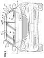
図面を参照すると、いくつかの視野において、同様の参照符号は、対応する部品を表し、窓組立体は、通常、20で表される。図1に示すように、窓組立体20は、車両22に適する。図1に示すように、窓組立体20は、フロントウィンドウ(フロントガラス)であってもよい。あるいは、窓組立体20は、リアウインドウ(後部窓)、ルーフウィンドウ(サンルーフ)、または車両22の他のいかなる窓であってもよい。通常、車両22は、開口を定め、窓組立体20は、この開口を封止する。開口は、通常、車両22の窓枠により定められる。
Referring to the drawings, in some views, like reference numerals represent corresponding parts, and the window assembly is typically represented by 20. As shown in FIG. 1, the
窓組立体20は、基板24を有し、この基板は、実質的に透明である。本願において使用される、「透明」という用語は、光に対する視覚的な透明性を表す。「実質的に透明」と言う用語は、通常、60%を超える可視光透過率を有するものとして定められる。ある実施例では、基板24の可視光透過率は、75%を超える。さらに別の実施例では、基板24の可視光透過率は、90%を超える。
The
ある実施例では、基板24は、単一の一体化形成されたピースである。別の実施例では、図10および図11に示すように、基板24は、外部基板26と、該外部基板に隣接して配置された内部基板28とを有する。外部基板26は、内部基板28と平行に、内部基板から離間して配置される。この実施例では、外部基板26および内部基板28が相互に接合され、基板24が形成される。外部基板26および内部基板28は、1枚ガラス(ガラスペイン)であることが好ましい。ガラスペインは、自動車ガラスであることが好ましく、ソーダライムシリカガラスであることがより好ましい。しかしながら、外部基板26および内部基板28は、プラスチック、ガラス繊維、または他の好適な非導電性の実質的に透明な材料であってもよい。
In one embodiment,
通常、外部基板26および内部基板28は、非導電性である。本願において、「非導電性」と言う用語は、通常、異なる電気的電位で導体の間に配置された際に、材料を介して流れる電流が無視できる、絶縁体または誘電体のような材料を表す。また、外部基板26および内部基板28は、光に対して実質的に透明である。ただし、外部基板26および内部基板28は、着色または染められていてもよい。
Usually, the
基板24は、複数の表面を有してもよい。例えば、図10および図11に示すように、外部基板26および内部基板28の各々は、内表面26a、28aと、外表面26b、28bとを有する。外部基板26の外表面26bは、通常、車両22の外部と面する。内部基板28の外表面28bは、通常、車両22の内部と面する。通常、外部基板26および内部基板28が相互に接合され、基板24が形成された際に、外部基板26および内部基板28の内表面26a、28aは、相互に対面する。
The
図2乃至9に示すように、基板24は、周30を定める。代わりに、周30は、基板24の周端部として定められてもよい。周30は、通常、上側周端部30aと、対向する下側周端部30bとを有する。周30は、通常、対向する側周端部30c、30dを有し、これらは、上側および下側周端部30a、30bに接続される。本願において、「上側」および「下側」という用語は、地表に対して基板24の周30を配向する際に利用され、上側周端部30aは、下側周端部30bよりも地表に対して高い位置となるように配置される。ただし、「上側」および「下側」と言う用語は、上側および下側周端部30a、30bの配向を限定することを意味するものではない。従って、上側および下側周端部30a、30bは、本発明の範囲から逸脱しない範囲で、別の配置を有してもよい。また、上側、下側、および/または側周端部30a、30b、30c、30dは、曲線状であっても直線状であってもよい。
As shown in FIGS. 2-9, the
車両22のフロントガラスとして利用される場合、基板24の周30は、通常、図1乃至9に示すような台形状の構成を有する。ただし、基板24の周30は、本願には具体的には記載されていない他の形状を有してもよい。
When used as the windshield of the
図3乃至図5に示すように、軸40は、基板24の上側および下側周端部30a、30bの間を垂直に延伸する。図3乃至図5における軸40は、通常、基板24の周30を、2つの非合同領域に分割する。図6では、軸40は、側周端部30c、30dの間を水平に延在する。この実施例では、軸40は、基板24の周30を、2つの非合同領域に分割する。
As shown in FIGS. 3 to 5, the
図に示すように、窓組立体20は、透明層50を有する。透明層50は、基板24の表面に配置される。ある実施例では、図10に示すように、透明層50は、内部基板28の外表面28bに配置される。別の実施例では、図11に示すように、透明層50は、外部基板26の内表面26aと内部基板28の内表面28aの間に配置される。そのような例では、透明層50は、該透明層50に損傷を及ぼし得る環境因子との直接の接触から保護される。透明層50は、窓組立体20の他の表面に配置されてもよい。例えば、透明層50は、内部基板28の内表面28a、または外部基板26の内表面26もしくは外表面26bに配置されてもよい
必須ではないが、図10および図11に示すように、外部基板26と内部基板28の内表面26a、28aの間には、中間層29が配置されてもよい。中間層29は、外部基板26と内部基板28を結合し、窓組立体20が衝撃の際に粉砕されることを抑制することが好ましい。また、中間層29は、通常、光に対して透明であり、ポリビニルブチラール(PVB)のような、高分子または熱可塑性樹脂を含む。しかしながら、中間層29の実施の際には、他の好適な材料も利用可能である。通常、中間層29は、0.5mmから1mmの間の厚さを有する。
As shown in the figure, the
中間層29は、透明層50に隣接して配置されてもよい。ある実施例では、図10に示すように、中間層29は、透明層50と外部基板26の内表面26aの間に配置される。あるいは、透明層50は、中間層29と内部基板28の内表面28aとの間に配置されてもよい。窓組立体20は、外部基板26と内部基板28の間に挟まれた、透明層50および中間層29を有することが好ましく、この場合、中間層29および透明層50は、外部基板26および/または内部基板28の内表面26a、28aと接する。あるいは、図には示されていないが、透明層50は、中間層29内に埋設されてもよく、この場合、透明層50は、両側が中間層29の間に挟まれることが理解される。
The
透明層50は、光に対して実質的に透明である。従って、車両22のドライバまたは乗員は、透明層50を有する基板24を介して、外を見ることができる。透明層50は、基板24に侵入する太陽からの熱を反射することが好ましい。その場合、透明層50は、基板24を介した赤外放射線の透過を抑制する。透明層50は、さらに、防曇素子または霜取り素子として作動され、基板24に加熱機能が提供されてもよい。
The
ある実施例では、透明層50は、膜である。別の実施例では、透明層50は、コーティングである。透明層50は、例えば、化学気相成膜法、マグネトロンスパッタ気相成膜法、スプレー熱分解法など、いかなる好適な方法で基板24の表面に適用されてもよい。
In some embodiments, the
透明層50は、透明層50が導電性となるような金属化合物を含む。本願において、「導電性」と言う用語は、通常、導体のような、材料を通じて効果的に電流が流れる、低い電気抵抗を示す材料を表す。金属化合物は、金属酸化物を含むことが好ましい。ただし、金属化合物は、さらに、金属窒化物等を含んでもよい。金属酸化物は、インジウムスズ酸化物などのような、スズ酸化物を含んでもよい。しかしながら、透明層50は、他の金属酸化物を含んでもよく、これには、これに限られるものではないが、銀酸化物が含まれる。また金属化合物は、フッ素のような添加剤でドープされてもよい。特に、添加剤は、金属化合物に含まれ、透明層50の光透過性および電気抵抗を最適化してもよい。透明層50は、該透明層50を通る電流の流れに対抗するための透明層50の機能を定量化する、いかなる好適なシート電気抵抗を有してもよい。シート抵抗は、表面抵抗としても知られる。ある例では、透明層24は、0.5〜20Ω/□の間の範囲のシート抵抗を有してもよい。
The
ある実施例では、透明層50は、基板24の表面の少なくとも大部分を占める。本願において、大部分とは、基板24の表面積の50%よりも大きいものとして定められる。通常、透明層50は、基板24を介した赤外放射線の透過を最大限抑制するため、表面の少なくとも大部分を被覆する。別の実施例では、透明層50は、表面の小部分を占めてもよい。あるいは、透明層50は、基板24の全体を占めてもよく、その場合、透明層50は、基板24の周30まで延伸する。透明層50は、基板24の周30と実質的に等しい形状を定めてもよい。あるいは、透明層50は、いかなる好適な形状を有してもよい。
In certain embodiments, the
図1乃至図9に示すように、基板24上の、透明層50と基板24の周30の間には、外側領域56が形成される。外側領域56は、透明層50が欠落している領域であり、従って、非導電性である。外側領域56は、透明層50と基板24の周30の間の距離として定められた幅を有する。幅は、0mmよりも大きく、200mmよりも小さいことが好ましい。
As shown in FIGS. 1 to 9, an
ミラーまたは雨センサのような車両装置が、基板24に取り付けられ、または設置されてもよい。車両装置が基板24に取り付けられた位置における透明層50の存在により、車両装置の特性に悪影響が生じ得る。従って、透明層50は、通常基板24の上側周端部30aの近傍に開口を有し、基板24に車両装置のアタッチメントが収容される。ある実施例では、図2乃至4に示すように、開口は、外側領域56が基板24の上側周30aの近傍で拡張されるように、外側領域56に開放されている。開口は、いかなる好適な形状を有しても良く、図2乃至図4に示すようなU字型等であってもよい。別の実施例では、開口は、該開口が外側領域56から分離され、外側領域56には延伸しないように、透明層50に取り囲まれる。開口が必要な場合、透明層50は、本発明が適正に機能するように、必要な範囲で変更されてもよい。
Vehicle devices such as mirrors or rain sensors may be attached to or installed on the
透明層50は、第1の領域60および第2の領域62を定める。第1および第2の領域60、62は、相互に非合同である。第1および第2の領域60、62の各々は、面積と形状を定める。本願において、「非合同」と言う用語は、通常、第1および第2の領域60、62の形状またはサイズが一致しないことを意味する。換言すれば、第1および第2の領域60、62は、幾何学図形的に非合同である。
The
ある実施例では、「非合同」と言う用語は、さらに、第1の領域60の面積が、第2の領域62の面積の少なくとも5%大きくまたは小さいことを意味するものとして規定される。別の実施例では、「非合同」と言う用語は、さらに、第1の領域60の形状が、第2の領域62の形状よりも少なくとも5%、幾何学的に異なることを意味するものとして規定される。幾何学的な差異は、第1および/または第2の領域60、62のスケール化(比例的拡大または縮小)、回転処理、平行移動処理、および/または反射処理により評価され、第1および第2の領域60、62の形状は、できる限り幾何学的に整列される。
In some embodiments, the term “non-congruent” is further defined to mean that the area of the
第1および第2の領域60、62は、各種構成を有してもよい。ある実施例では、図5に示すように、第1および第2の領域60、62は、同様の形状を有するが、異なる面積を有し、第1および第2の領域60、62は、非合同である。別の実施例では、第1および第2の領域60、62は、同様の面積を有するものの、異なる形状を有するため、第1および第2の領域60、62は、非合同であってもよい。図7では、第1の領域60は、第2の領域62を完全に取り囲んでいる。図2では、第1の領域60は、第2の領域62を部分的に取り囲んでいる。
The first and
別の実施例では、第1および第2の領域60、62は、透明層50に定められた複数の領域の一つであってもよい。例えば、図8および図9に示すように、透明層50は、第1の領域60、第2の領域62、および第3の領域を定める。図8において、第1の領域60および第3の領域は、サイズおよび形状が実質的に合同であるものの、第2の領域62は、第1の領域60および第3の領域の関して、非合同である。図9では、第1の領域60、第2の領域62、および第3の領域は、相互に非合同であり、いずれの2つの領域も、同じサイズおよび形状を有しない。
In another embodiment, the first and
第1の領域60は、第1の周囲70を定め、第2の領域62は、第2の周囲80を定める。第1および第2の周囲70、80の各々は、外側端部70a、80a、および内側端部70b、80bを有してもよい。第1および第2の周囲70、80の各々において、外側端部70a,80aは、通常、内側端部70b、80bと対向する。本願において、「内側」と言う用語は、第1および第2の周70、80の内側端部70b、80bが相互に隣接して対面するようにして、第1および第2の周囲70、80を配向する際に利用される。ある実施例では、第1および第2の周囲70、80の各々は、さらに、側端部70c、80cと、対向する側端部70d、80dとを有し、これらは、外側端部70a、80aおよび内側端部70b、80bに接続される。
The
第1および第2の周囲70、80は、本発明の範囲から逸脱しないで、いかなる好適な形状を有してもよい。例えば、主に図面に示すように、第1および第2の周囲70、80は、四角形の構成を有する。ただし、第1および第2の周囲70、80は、他の構成を有しても良く、これには、これに限られるものではないが、円形または任意の多角形の構成が含まれる。
The first and
第1および第2の周囲70、80は、各種異なる配置により、基板24の周30に対して配向されてもよい。例えば、図1、3〜5、8、および9に示すように、第1および第2の周囲70、80の各々の内側端部70b、80bは、基板24の上側および下側周端部30a、30bと実質的に直交するように配置される。別の例では、図6に示すように、第1および第2の周囲70、80の各々の内側端部70b、80bは、基板24の上側および下側周端部30a、30bと実質的に平行に配置される。
The first and
ある実施例では、第1の周囲70の内側端部70bおよび第2の周囲80の内側端部80bの各々は、直線状の配置を有する。内側端部70b、80bは、実質的に相互に平行に延伸してもよい。図3乃至図6に示すように、第1の周囲70の内側端部70bおよび第2の周囲80の内側端部80bは、軸40から均等に離間されてもよい。換言すれば、軸40は、内側端部70b、80bから等距離にある。内側端部70b、80bは、10mm未満だけ離間されることが好ましい。別の実施例では、内側端部70b、80bは、非直線状の配置であり、内側端部70b、80bは、相互に平行に延伸しない。また、内側端部70b、80bは、図5に示すように、10mmを超えるような、いかなる好適な距離だけ離間されてもよい。
In one embodiment, each of the
第1および第2の領域60、62は、各々、無線周波数信号を送信および/または受信する、アンテナ素子として作動するように構成される。第1および第2の領域60、62の各々は、直線偏向もしくは円偏向された無線周波数信号を、送信および/または受信するように構成されてもよい。特に、第1および第2の領域60、62により送信および/または受信される直線偏向されたRF信号は、これに限られるものではないが、AM、FM、RKE(リモートキーレスエントリ)、DAB(デジタルオーディオブロードキャスティング)、およびTV信号を含む。第1および第2の領域60、62により送信および/または受信される円偏向されたRF信号は、これに限られるものではないが、SDARS(衛星ラジオ)またはGPS信号を含む。図1に示すように、第1および第2の領域60、62には、アンテナ受信器82が接続され、第1および第2の領域60、62により受信されるラジオ周波数信号が処理される。
The first and
非合同の第1および第2の領域60、62により、該第1および第2の領域60、62は、異なる周波数で作動し、これにより、窓組立体20に、多様化された(diversified)アンテナ機能が提供される。例えば、第1の領域60は、該第1の領域60がTV信号を受信するように寸法化され、第2の領域62は、該第2の領域62がFM信号を受信するように寸法化される。通常、第1および第2の領域60、62の各々は、一つのタイプのアンテナ周波数用の送信および/または受信が可能となるように構成される。しかしながら、第1および第2の領域60、62の各々は、2種類以上のアンテナ周波数用に利用されてもよい。
Due to the non-congruent first and
第1および第2の領域60、62は、区画カット部86により、相互に離間される。区画カット部86は、透明層50の欠落部分であり、非導電性である。通常、区画カット部86は、該区画カット部86および外側領域56が共通の非導電性領域を形成するようにして、外側領域56に開かれている。区画カット部86は、第1および第2の周囲70、80の各々の内側端部70b、80bにより定められる。図1乃至図9に示す実施例では、区画カット部86は、隣接する第1および第2の領域60、62により定められた、直線状の配置を有する。区画カット部86の直線状の配置は、第1および第2の周囲70、80の隣接する内側端部70b、80bにより定められてもよい。前述のように、内側端部70b、80bは、10mm未満だけ離間されることが好ましい。その場合、区画カット部86は、10mm未満の幅であることが好ましい。別の実施例では、区画カット部86は、曲線を有する配置など、非直線状の配置を有してもよい。前述のように、区画カット部86は、図5に示すように、10mmよりも広くてもよい。区画カット部86は、必ずしも直線である必要はない。換言すれば、区画カット部86は、図2に示すような多セグメント配置、または図7に示す閉止ループ配置など、他の形態を取ってもよい。
The first and
区画カット部86は、従来のいかなる好適な技術で、基板24上に形成されてもよい。例えば、区画カット部86を定める透明層50の領域の除去または削除は、マスク処理、レーザ、研磨ツール、化学的除去、機械的切断ツール等を用いて実施されてもよい。
The partition cut
図1に示すように、窓組立体20は、給電配置90を有し、これは、透明層50に結合され、より具体的には、第1および第2の領域60、62に結合される。給電配置90は、第1および第2の領域60、62が無線周波数信号を送信および/または受信するように、第1および第2の領域60、62をエネルギー化する。第1および第2の領域60、62は、給電配置90を介して、アンテナ受信器82に接続される。
As shown in FIG. 1, the
給電配置90に関し、「エネルギー化」と言う用語は、給電配置90と第1および第2の領域60、62との間の電気的な関係を説明するものであり、これにより給電配置90は、無線波の送信のため第1および第2の領域60、62を励起し、入射する無線波の受信のため第1および第2の領域60、62と電気的に結合されることが理解される。
With respect to the
給電配置90は、第1および第2の領域60、62をエネルギー化する、いかなる好適な構成を有してもよい。図10および図11に示すように、給電配置90は、通常、各領域60、62用の、少なくとも一つの給電素子92を有する。通常、第1および第2の領域60、62の各々には、一つの給電素子92のみが必要となる。しかしながら、本発明の範囲から逸脱しないで、第1および第2の領域60、62のいずれかに対して、複数の給電素子92を用いても良い。ある実施例では、図1に示すように、給電配置90は、2つの別個の給電素子92を有し、各々は、第1および第2の領域60、62の一つに、別個に結合される。別の実施例では、給電配置90は、一つの給電素子90を有し、これは、第1および第2の領域60、62の両方に結合される。給電素子92は、第1および第2の領域60、62をエネルギー化する、いかなる好適な材料を含んでもよい。また、給電素子92は、いかなる好適な配置を有してもよく、これには、これに限られるものではないが、給電ストリップ、給電配線、またはこれらの組み合わせが含まれる。
The
給電素子92は、基板24のいかなる表面に配置されてもよい。また、給電素子92は、透明層50と同一平面上に、または異なる平面上に、配置されてもよい。主として図に示したように、第1および第2の領域60、62の各々は、透明層50のタブ94を有し、これは、第1および第2の領域60、62のそれぞれから、一体的に延伸してもよい。タブ94は、第1および第2の周囲70、80のそれぞれを超えて、外側領域56に延伸する。タブ94により、給電素子92は、第1および第2の領域60、62と容易に接続され、基板24を介した視野が妨害されることもない。
The
ある実施例では、図10に示すように、給電素子92は、透明層50と境界を接し、透明層50と電気的に直接接触する。ここでは、給電素子92は、透明層50に直接配線され、または透明層50にはんだ付けされてもよい。給電素子92は、給電ストリップまたは配線のような、透明層50に物理的に取り付けられた導電性材料を介して、直接、透明層50に電流を供給する。給電素子92は、透明層50と境界を接し、電気的に直接接触するが、透明層50は、基板24のいかなる層の上に配置されてもよい。
In one embodiment, as shown in FIG. 10, the
あるいは、図11に示すように、給電素子92は、透明層50から離間され、透明層50と容量的に結合されてもよい。そのような例では、給電素子92は、外部または内部基板26、28のような、空気または誘電体材料を介して、透明層50に電流を誘導する。そのような実施例では、給電素子92は、通常、透明層50と直接配線されたり、直接接触したりすることはない。給電素子92は、通常、透明層50とは異なる平面上に配置される。第1および第2の領域60、62は、本願で具体的に示されていない、他の構成による給電配置90によりエネルギー化されてもよい。
Alternatively, as shown in FIG. 11, the feeding
図面に示されているように、第1および第2の領域60、62の各々は、少なくとも一つの特性増強スリット96(以降、簡略化のため「スリット」と称される)を定め、ここには、透明層50は存在しない。換言すれば、第1の領域60は、少なくとも第1のスリット96aを定め、第2の領域62は、少なくとも第2のスリット96bを定める。スリット96a、96bは、インピーダンス整合素子および放射パターン変更素子の少なくとも一つとして作動するように構成される。ある実施例では、スリット96a、96bは、インピーダンス整合素子のみとして作動するように構成される。別の実施例では、スリット96a、96bは、放射パターン変更素子のみとして作動するように構成される。当然のことながら、スリット96a、96bは、インピーダンス整合素子および放射パターン変更素子の両方として、同時に作動するように構成されてもよい。また、スリット96aの一つはインピーダンス整合素子として作動し、他のスリット96bは放射パターン変更素子として作動し、またはその逆であってもよい。
As shown in the drawings, each of the first and
スリット96a、96bは、第1および第2の領域60、62のインピーダンスを、ケーブルのインピーダンスと整合させることにより、インピーダンス整合素子として作動する。ケーブルは、以下に示すように、例えば、第1および/または第2の領域60、62のエネルギー化に利用される同軸ケーブルであってもよい。
The
スリット96a、96bは、第1および/または第2の領域60、62から送信および/または受信される無線信号の方向を変えることにより、放射パターン変更素子として作動する。より具体的には、スリット96a、96bは、第1および/または第2の領域60、62の放射パターンがより大きな全方向性を示すように、無線信号が送信および/または受信される方向を変更する。スリット96a、96bにより、アンテナ素子として作動する、第1および第2の領域60、62のインピーダンス特性および放射パターンにわたって、大きな制御が可能となる。スリット96a、96bは、電磁波干渉を低減することを助長し、最適な効率が得られる。従って、スリット96a、96bは、第1および/または第2の領域60、62の特性を高める。スリット96a、96bは、該スリット96a、96bにより、車両22のドライバまたは乗員の視界の妨害が最小限となるように配置されることが好ましい。
The
前述のように、透明層50、より具体的には、第1および/または第2の領域60、62は、必要な場合、さらに、防曇素子また霜取り素子として作動されてもよい。そのような例では、本発明の範囲から逸脱しないで、第1の領域60、第2の領域62、および/またはスリット96a、96bは、透明層50の任意の防曇または霜取り機能を提供するように変更されてもよい。
As mentioned above, the
ある実施例では、スリット96a、96bは、第1および第2の領域60、62の一方の透明層50により定められるような、直線状の配置を有する。スリット96a、96bの配置状構成を定める透明層50は、2mm未満で均一に離間されることが好ましい。別の実施例では、スリット96a、96bは、曲線を有する配置、ジグザグ配置など、非直線状の配置を有する。
In one embodiment, the
スリット96a、96bは、各種好適な長さに延伸してもよい。主として図面に示すように、第1のスリット96aは、第1の長さで延伸し、第2のスリット96bは、第2の長さで延伸し、ここで、第1の長さは第2の長さとは異なってもよい。ある例では、スリット96aの一つは、100mm未満の長さを有し、他のスリット96bは、200mmを超える長さを有してもよい。第1のスリット96aおよび第2のスリット96bは、異なる長さであり、非合同の寸法の第1および第2の領域60、62が提供されてもよい。あるいは、図3に示すように、第1のスリット96aは、第1の長さで延伸し、第2のスリット96bは、第2の長さで延伸し、ここで第1の長さは第2の長さと等しくてもよい。
The
スリット96a、96bは、従来のいかなる好適な技術で基板24上に形成されてもよい。例えば、スリット96に対応する透明層50の選択部分の除去または削除は、マスク処理、レーザ、研磨ツール、化学的除去、機械的切断ツールなどを用いて行われてもよい。
The
ある実施例では、図3乃至図5に示すように、第1の領域60は、第1のスリット96aを定め、第2の領域62は、第2のスリット96bを定める。第1および第2のスリット96a、96bは、相互に軸40に対して配置される。図4、図5に示すように、第1および第2のスリット96a、96bは、軸40と実質的に直交するように配向される。あるいは、図3に示すように、第1および第2のスリット96a、96bは、軸40に対して実質的に平行に配向される。
In one embodiment, as shown in FIGS. 3-5, the
別の実施例では、図1〜4、6、7、9に示すように、スリット96a、96bは、それぞれの第1および第2の周囲70、80から、第1および第2の領域60、62に延伸する。例えば、図4に示すように、第1のスリット96aは、第1の周囲70から第1の領域60に延伸し、第2のスリット96bは、第2の周囲80から第2の領域62に延伸する。ここで、第1および第2のスリット96a、96bは、通常、外側領域56に開かれている。ある例では、第2のスリット96bではなく、第1のスリット96aが外側領域56に開かれている。例えば、図7に示すように、第1の領域60は、第2の領域62を取り囲み、第2の領域62は、第1の領域60内に配置される。ここで、第1のスリット96aは、外側領域56に開かれている。第2のスリット96bは、外側領域56に開かれていない。代わりに、第2のスリット96bは、区画カット部86に対して開かれる。
In another embodiment, as shown in FIGS. 1-4, 6, 7, 9, the
ある実施例では、第1のスリット96aは、第1の周囲70における一つの位置から、第1の領域60に延伸する。同様に、第2のスリット96bは、第2の周囲80の一つの位置から、第2の領域62に延伸する。換言すれば、そのような例では、第1および第2のスリット96a、96bは、該第1および第2のスリット96a、96bが、それぞれの第1および第2の領域60、62を、より小さな領域に完全に分割するほど、それぞれの第1および第2の領域60、62にわたって延伸しない。
In one embodiment, the
別の実施例では、図5に示すように、スリット96a、96bは、第1および第2の周囲70、80の一方の内部に定められ、スリット96a、96bは、透明層50によって取り囲まれる。例えば、図5において、第1のスリット96aは、第1の周囲70内に、第1のスリット96aが第1の領域60の透明層50で取り囲まれるように定められる。同様に、第2のスリット96bは、第2の周囲80内に、第2のスリット96bが第2の領域62の透明層50で取り囲まれるように定められる。ここで、第1および第2のスリット96a、96bは、外側領域56から離間され分離され、第1および第2のスリット96a、96bは、外側領域56で開かれていない。当然のことながら、第1および第2のスリット96a、96bの任意の単一のものが透明層50に取り囲まれ、第1および第2のスリット96a、96bの他のものは、それぞれの第1および第2の周囲70、80の一つから、第1および第2の領域60、62の一つに延伸してもよい。
In another embodiment, as shown in FIG. 5, the
さらに別の実施例では、第1のスリット96aは、第1の周囲70の側端面70cまたは対向する側端面70dの少なくとも一つに略平行に延伸する。同様に、第2のスリット96bは、第2の周囲80の側端面80cまたは対向する側端面80dの少なくとも一つに略平行に延伸してもよい。あるいは、第1のスリット96aは、第1の周囲70の外側端部および内側端部70a、70bの一つと略平行に延伸してもよい。同様に、第2のスリット96bは、第2の周囲80の外側端部および内側端部80a、80bの一つと略平行に延伸してもよい。
In yet another embodiment, the
別の実施例では、第1または第2のスリット96a、96bは、第1および第2の周囲70、80、または周30の任意の所与の側または端部に対して、所定の角度で延伸してもよい。例えば、図6に示すように、第1および第2のスリット96a、96bは、窓組立体20の中心に向かって内側に傾斜し、第1および第2のスリット96a、96bは、周30、または第1および第2の周囲70、80のいずれに対しても、平行にあるいは直交して延伸しない。図6における所定の角度は、第2の周囲80の周端部30bおよび側部30bに対して約45゜である。所定の角度は、区画カット部86、外側領域56、または周囲70、80のような、窓組立体20の他の特徴物により定められてもよい。
In another embodiment, the first or
第1および第2の領域60、62は、2以上のスリット96を有してもよい。図3乃至図8に示すように、第1および第2の領域60、82の各々は、スリット96の組を有する。例えば、図4の実施例では、第1の領域60は、第1のスリット96aおよび第3のスリット96cを定める。第2の領域62は、第2のスリット96bおよび第4のスリット96dを定める。
The first and
第1の領域60および第2の領域62は、必ずしも同じ数のスリット96を有する必要はない。第1の領域60および第2の領域62は、異なる数のスリット96を定めてもよい。例えば、図2に示すように、第1の領域60は、一つのスリット96aを有するのに対して、第2の領域62は、2つのスリット96b、96dを有する。本発明の範囲から逸脱しない限り、第1および第2の領域60、62は、本願で示すような、スリット96のいかなる組み合わせを有してもよい。
The
本発明の窓組立体20は、通常の産業上の標準アンテナに比べて、良好なアンテナ特性を示す。図12には、窓組立体20の垂直偏向アンテナゲイン特性を、通常の産業上の標準アンテナと比べて示したチャートを示す。図13には、窓組立体20の水平偏向アンテナゲイン特性を、通常の産業上の標準的な特性と比べて示したチャートを示す。図12および図13では、図4の実施例からの窓組立体20の特性が、通常の産業上の標準アンテナと比較される。ただし、図面に示され記載された、各種他の実施例の窓組立体20も、図4の窓組立体20と同様の特性を示すことは明らかである。図12および図13のチャートに示されているように、窓組立体20は、87〜108MHzのFM周波数範囲において、dB単位で、通常の産業上の標準特性に比べて、良好な垂直および水平偏向の平均ゲインを示す。特に、図12では、窓組立体20は、93〜108MHzの間における通常の産業上の標準特性に比べて、少なくとも10dB大きな垂直偏向平均ゲインを一貫して示す。図13において、窓組立体20は、少なくとも10dBの平均値を一貫して示しており、ある周波数では、98〜108MHzの間で、通常の産業上の標準特性と比較して、25dBの大きな水平偏向平均ゲインが得られている。
The
一例を示して、本発明について説明した。使用用語は、限定的なものではなく、記載の用語の性質を意図するものであることが理解される。前述の示唆に鑑みて、多くの変更および修正が可能であることは、明らかである。本発明は、添付の特許請求の範囲から逸脱せずに、具体的に示されたもの以外の方法で実施されてもよい。 The present invention has been described with an example. It is understood that the terminology used is not limiting and is intended to be in the nature of the terminology described. Obviously, many modifications and variations are possible in view of the above suggestions. The present invention may be practiced otherwise than as specifically described without departing from the scope of the appended claims.
Claims (10)
表面を有し、実質的に透明な基板であって、周を定める基板と、
前記表面に配置され、金属化合物を含む導電性の透明層であって、該透明層は、区画カット部により相互に離間された第1の領域および第2の領域を定め、前記区画カット部では前記透明層が欠落しており、前記第1および第2の領域は、相互に非合同である、透明層と、
前記基板上の前記透明層と前記基板の前記周の間に形成された、非導電性の外側領域と、
前記第1および第2の領域に結合され、前記第1および第2の領域をエネルギー化する給電配置と、
を有し、
前記第1の領域は、前記透明層の欠落部である第1のスリットを定め、
前記第2の領域は、前記透明層の欠落部である第2のスリットを定め、
前記第1および第2のスリットの少なくとも一つは、前記外側領域に開かれている、窓組立体。 A vehicle window assembly comprising:
A substantially transparent substrate having a surface and defining a circumference ;
A conductive transparent layer disposed on the surface and containing a metal compound, the transparent layer defining a first region and a second region separated from each other by a partition cut portion; The transparent layer is missing, and the first and second regions are non-congruent with each other, and the transparent layer;
A non-conductive outer region formed between the transparent layer on the substrate and the circumference of the substrate;
A power feeding arrangement coupled to the first and second regions and energizing the first and second regions;
Have
The first region defines a first slit the a missing portion of the transparent layer,
The second region defines a second slit the a missing portion of the transparent layer,
The window assembly , wherein at least one of the first and second slits is open to the outer region .
前記第1および第2のアンテナ素子は、無線信号を送信および/または受信するように構成される、請求項1に記載の窓組立体。 The first region is a first antenna element, the second region is a second antenna element,
The window assembly of claim 1, wherein the first and second antenna elements are configured to transmit and / or receive radio signals.
前記第1のスリットの前記直線配置を定める前記透明層は、2mm以下で均一に離間される、請求項1乃至5のいずれか一つに記載の窓組立体。 The first slit has a linear arrangement defined by the transparent layer of the first region;
6. The window assembly according to claim 1, wherein the transparent layers that define the linear arrangement of the first slits are uniformly spaced by 2 mm or less.
前記区画カット部は、さらに、前記第1の周囲と前記第2の周囲の間に定められる、請求項1乃至6のいずれか一つに記載の窓組立体。 The first region defines a first periphery, the second region defines a second periphery;
7. The window assembly according to claim 1, wherein the partition cut portion is further defined between the first periphery and the second periphery.
10. The substrate according to any one of claims 1 to 9 , wherein the substrate has an outer substrate having an inner surface and an outer surface, and an inner substrate disposed adjacent to the outer substrate and having an inner surface and an outer surface. A window assembly as described.
Applications Claiming Priority (3)
| Application Number | Priority Date | Filing Date | Title |
|---|---|---|---|
| US201361793958P | 2013-03-15 | 2013-03-15 | |
| US61/793,958 | 2013-03-15 | ||
| PCT/US2014/014439 WO2014143442A1 (en) | 2013-03-15 | 2014-02-03 | Window assembly with transparent regions having a performance enhancing slit formed therein |
Publications (3)
| Publication Number | Publication Date |
|---|---|
| JP2016515354A JP2016515354A (en) | 2016-05-26 |
| JP2016515354A5 JP2016515354A5 (en) | 2016-08-12 |
| JP6087019B2 true JP6087019B2 (en) | 2017-03-01 |
Family
ID=50159531
Family Applications (2)
| Application Number | Title | Priority Date | Filing Date |
|---|---|---|---|
| JP2016500199A Active JP6087019B2 (en) | 2013-03-15 | 2014-02-03 | Window assembly with a transparent region having a property enhancing slit |
| JP2016500198A Active JP6490047B2 (en) | 2013-03-15 | 2014-02-03 | Window assembly with a transparent region having a property enhancing slit |
Family Applications After (1)
| Application Number | Title | Priority Date | Filing Date |
|---|---|---|---|
| JP2016500198A Active JP6490047B2 (en) | 2013-03-15 | 2014-02-03 | Window assembly with a transparent region having a property enhancing slit |
Country Status (5)
| Country | Link |
|---|---|
| US (2) | US9960482B2 (en) |
| EP (2) | EP2973845B1 (en) |
| JP (2) | JP6087019B2 (en) |
| CN (2) | CN105229849B (en) |
| WO (2) | WO2014143442A1 (en) |
Families Citing this family (14)
| Publication number | Priority date | Publication date | Assignee | Title |
|---|---|---|---|---|
| DE102012012566B3 (en) * | 2012-06-23 | 2013-12-05 | Audi Ag | Composite pane for a motor vehicle and motor vehicle with such a composite pane. |
| WO2014143442A1 (en) | 2013-03-15 | 2014-09-18 | Agc Automotive Americas R&D, Inc. | Window assembly with transparent regions having a performance enhancing slit formed therein |
| US8927069B1 (en) * | 2013-10-02 | 2015-01-06 | Eritek, Inc. | Method and apparatus for improving radio frequency signal transmission through low-emissivity coated glass |
| US9806398B2 (en) * | 2014-01-22 | 2017-10-31 | Agc Automotive Americas R&D, Inc. | Window assembly with transparent layer and an antenna element |
| US9406996B2 (en) * | 2014-01-22 | 2016-08-02 | Agc Automotive Americas R&D, Inc. | Window assembly with transparent layer and an antenna element |
| JP6812730B2 (en) | 2015-10-09 | 2021-01-13 | Agc株式会社 | Front window for vehicles and articles for vehicles using it |
| US10490877B2 (en) * | 2016-05-06 | 2019-11-26 | GM Global Technology Operations LLC | CPW-fed circularly polarized applique antennas for GPS and SDARS bands |
| US10396427B2 (en) * | 2016-05-06 | 2019-08-27 | GM Global Technology Operations LLC | Dual polarized wideband LTE thin film antenna |
| US10714809B2 (en) * | 2016-05-10 | 2020-07-14 | AGC Inc. | Antenna for vehicle |
| PL3487720T3 (en) | 2016-07-20 | 2021-09-20 | Saint-Gobain Glass France | Window pane with capacitive range for touch-free control of a function |
| DE102017210989B3 (en) * | 2017-06-28 | 2018-05-17 | Audi Ag | Laminated glass for a vehicle |
| US10673122B2 (en) * | 2017-10-20 | 2020-06-02 | Gentex Corporation | Vehicle communication module with improved transmission |
| JP7077718B2 (en) * | 2018-03-29 | 2022-05-31 | 豊田合成株式会社 | Radio wave transmission cover |
| US11955713B2 (en) | 2020-06-30 | 2024-04-09 | Novatel Inc. | Antenna with tilted beam for use on angled surfaces |
Family Cites Families (163)
| Publication number | Priority date | Publication date | Assignee | Title |
|---|---|---|---|---|
| US3177489A (en) | 1960-01-11 | 1965-04-06 | Thompson Ramo Wooldridge Inc | Interference suppression systems |
| US3870996A (en) | 1963-09-16 | 1975-03-11 | Us Navy | Jamming cancellation device |
| US3603886A (en) | 1966-01-04 | 1971-09-07 | Gene M Norrs | Noise rejecting signal filter |
| US3359555A (en) | 1966-08-30 | 1967-12-19 | Ralph E Taylor | Polarization diversity monopulse tracking receiver |
| US3670335A (en) | 1967-06-08 | 1972-06-13 | Bell Telephone Labor Inc | Arrays with nulls steered independently of main beam |
| US4103304A (en) | 1973-04-20 | 1978-07-25 | Litton Systems, Inc. | Direction locating system |
| FR2250329A5 (en) | 1973-10-31 | 1975-05-30 | Saint Gobain | |
| US3964065A (en) | 1974-12-17 | 1976-06-15 | The United States Of America As Represented By The Secretary Of The Army | Steerable antenna null combiner system |
| US4051474A (en) | 1975-02-18 | 1977-09-27 | The United States Of America As Represented By The Secretary Of The Air Force | Interference rejection antenna system |
| US4057803A (en) | 1976-04-08 | 1977-11-08 | The United States Of America As Represented By The Secretary Of The Navy | Adaptive direction of arrival antennae system |
| US4085368A (en) | 1976-08-30 | 1978-04-18 | Bell Telephone Laboratories, Incorporated | Interference canceling method and apparatus |
| US4220954A (en) | 1977-12-20 | 1980-09-02 | Marchand Electronic Laboratories, Incorporated | Adaptive antenna system employing FM receiver |
| US4225870A (en) | 1978-05-10 | 1980-09-30 | The United States Of America As Represented By The Secretary Of The Army | Null steering antenna |
| US4189733A (en) | 1978-12-08 | 1980-02-19 | Northrop Corporation | Adaptive electronically steerable phased array |
| US4308541A (en) | 1979-12-21 | 1981-12-29 | Nasa | Antenna feed system for receiving circular polarization and transmitting linear polarization |
| US4313116A (en) | 1980-01-30 | 1982-01-26 | Westinghouse Electric Corp. | Hybrid adaptive sidelobe canceling system |
| US4280128A (en) | 1980-03-24 | 1981-07-21 | The United States Of America As Represented By The Secretary Of The Army | Adaptive steerable null antenna processor |
| US4298873A (en) | 1981-01-02 | 1981-11-03 | The United States Of America As Represented By The Secretary Of The Army | Adaptive steerable null antenna processor |
| US5107273A (en) | 1981-05-11 | 1992-04-21 | The United States Of America As Represented By The Secretary Of The Army | Adaptive steerable null antenna processor with null indicator |
| US4408205A (en) | 1981-06-25 | 1983-10-04 | International Telephone And Telegraph Corporation | Multiple beam antenna feed arrangement for generating an arbitrary number of independent steerable nulls |
| JPS5873206A (en) | 1981-10-27 | 1983-05-02 | Radio Res Lab | Multibeam forming circuit |
| US6977611B1 (en) | 1985-03-04 | 2005-12-20 | Northrop Grumman Corporation | FM-CW altimeter detector |
| US4821039A (en) | 1985-05-01 | 1989-04-11 | Crane Patrick E | Dual polarized monopulse orthogonal superposition |
| JPS6245201A (en) | 1985-08-23 | 1987-02-27 | Asahi Glass Co Ltd | Glass antenna for automobile |
| US4803492A (en) | 1985-11-25 | 1989-02-07 | Central Glass Company, Limited | Vehicle window glass antenna |
| JPS6295317U (en) * | 1985-12-03 | 1987-06-18 | ||
| US4704724A (en) | 1985-12-05 | 1987-11-03 | Bell Communications Research, Inc. | Routing of network traffic |
| US4849992A (en) | 1986-01-13 | 1989-07-18 | Aiken Advanced Systems, Inc. | Pulse-on-pulse circuit and method |
| US4704734A (en) | 1986-02-18 | 1987-11-03 | Motorola, Inc. | Method and apparatus for signal strength measurement and antenna selection in cellular radiotelephone systems |
| JPS62193304A (en) * | 1986-02-20 | 1987-08-25 | Asahi Glass Co Ltd | Glass antenna |
| GB2193846B (en) * | 1986-07-04 | 1990-04-18 | Central Glass Co Ltd | Vehicle window glass antenna using transparent conductive film |
| JPS6338306A (en) * | 1986-08-04 | 1988-02-18 | Central Glass Co Ltd | Transparent glass antenna for vehicle |
| KR890001219A (en) | 1987-06-27 | 1989-03-18 | 노브오 사수가 | Automotive Receiver |
| US4814777A (en) | 1987-07-31 | 1989-03-21 | Raytheon Company | Dual-polarization, omni-directional antenna system |
| DE3808401A1 (en) | 1988-03-12 | 1989-09-21 | Blaupunkt Werke Gmbh | VEHICLE WINDOW WASHER |
| US5068668A (en) | 1989-09-06 | 1991-11-26 | Hughes Aircraft Company | Adaptive polarization combining system |
| JP3085581B2 (en) * | 1989-12-29 | 2000-09-11 | マツダ株式会社 | Glass antenna for vehicles |
| US5568158A (en) | 1990-08-06 | 1996-10-22 | Gould; Harry J. | Electronic variable polarization antenna feed apparatus |
| US5117236A (en) | 1990-10-19 | 1992-05-26 | Motorola, Inc. | Antenna pattern selection for optimized communications |
| CA2063914C (en) | 1991-06-12 | 2002-07-16 | George S. Cohen | Multiple beam antenna and beamforming network |
| US5317288A (en) | 1992-12-15 | 1994-05-31 | Space Systems/Loral, Inc. | Continuously variable electronically controlled phase shift circuit |
| US5377035A (en) | 1993-09-28 | 1994-12-27 | Hughes Aircraft Company | Wavelength division multiplexed fiber optic link for RF polarization diversity receiver |
| US5659572A (en) | 1993-11-22 | 1997-08-19 | Interdigital Technology Corporation | Phased array spread spectrum system and method |
| US5515059A (en) | 1994-01-31 | 1996-05-07 | Northeastern University | Antenna array having two dimensional beam steering |
| US5818385A (en) | 1994-06-10 | 1998-10-06 | Bartholomew; Darin E. | Antenna system and method |
| US5517686A (en) | 1994-09-29 | 1996-05-14 | Delco Electronics Corporation | Diversity receiver for FM stereo utilizing a pilot tone multiple for phase alignment of received signals |
| JPH08148921A (en) * | 1994-11-21 | 1996-06-07 | Nippon Sheet Glass Co Ltd | Glass antenna device for mobile telephone |
| JP3340271B2 (en) | 1994-12-27 | 2002-11-05 | 株式会社東芝 | Omnidirectional antenna |
| US5600333A (en) | 1995-01-26 | 1997-02-04 | Larsen Electronics, Inc. | Active repeater antenna assembly |
| GB9504096D0 (en) | 1995-03-01 | 1995-04-19 | Gasser Elaine | Antenna and assembly |
| US5528314A (en) * | 1995-05-22 | 1996-06-18 | General Motors Corporation | Transparent vehicle window antenna |
| US5603107A (en) | 1995-06-09 | 1997-02-11 | Ford Motor Company | Switching system for diversity antenna FM receiver |
| US5760740A (en) | 1995-08-08 | 1998-06-02 | Lucent Technologies, Inc. | Apparatus and method for electronic polarization correction |
| DE19532431C2 (en) * | 1995-09-02 | 1998-07-02 | Flachglas Automotive Gmbh | Antenna pane in at least one window opening of a metallic body of a motor vehicle, in particular a passenger car |
| JP3497672B2 (en) | 1996-09-18 | 2004-02-16 | 株式会社東芝 | Adaptive antenna and multi-carrier wireless communication system |
| CA2188845A1 (en) | 1996-10-25 | 1998-04-25 | Stephen Ross Todd | Diversity Antenna Selection |
| US5710995A (en) | 1997-01-16 | 1998-01-20 | Ford Motor Company | Adaptive antenna receiver |
| JPH10247869A (en) | 1997-03-04 | 1998-09-14 | Nec Corp | Diversity circuit |
| US6172970B1 (en) | 1997-05-05 | 2001-01-09 | The Hong Kong University Of Science And Technology | Low-complexity antenna diversity receiver |
| JP3892129B2 (en) | 1998-01-23 | 2007-03-14 | 松下電器産業株式会社 | Portable radio |
| US6125109A (en) | 1998-02-24 | 2000-09-26 | Repeater Technologies | Delay combiner system for CDMA repeaters and low noise amplifiers |
| JP3967452B2 (en) | 1998-03-13 | 2007-08-29 | 株式会社東芝 | Spread spectrum wireless transmission receiver |
| US5999138A (en) | 1998-03-30 | 1999-12-07 | Ponce De Leon; Lorenzo A. | Low power switched diversity antenna system |
| US6018315A (en) | 1998-05-04 | 2000-01-25 | Motorola, Inc. | Method and system for attitude sensing using monopulse GPS processing |
| DE19832228C2 (en) * | 1998-07-17 | 2002-05-08 | Saint Gobain Sekurit D Gmbh | Antenna disc for motor vehicles |
| JP2000049524A (en) | 1998-07-31 | 2000-02-18 | Nec Corp | Array antenna |
| US6175723B1 (en) | 1998-08-12 | 2001-01-16 | Board Of Trustees Operating Michigan State University | Self-structuring antenna system with a switchable antenna array and an optimizing controller |
| US6400317B2 (en) | 1998-09-21 | 2002-06-04 | Tantivy Communications, Inc. | Method and apparatus for antenna control in a communications network |
| FI105061B (en) | 1998-10-30 | 2000-05-31 | Lk Products Oy | Planar antenna with two resonant frequencies |
| JP2000156606A (en) | 1998-11-19 | 2000-06-06 | Harada Ind Co Ltd | Its adaptable car antenna device |
| GB2344221B (en) | 1998-11-30 | 2003-09-17 | Fujitsu Ltd | Receiving apparatus including adaptive beamformers |
| JP2000196329A (en) | 1998-12-24 | 2000-07-14 | Nec Corp | Phased array antenna and manufacture of the same |
| JP3481481B2 (en) | 1998-12-24 | 2003-12-22 | 日本電気株式会社 | Phased array antenna and manufacturing method thereof |
| US6314127B1 (en) | 1999-02-23 | 2001-11-06 | Lucent Technologies Inc. | System and method for enhancing signal reception |
| EP1032073A3 (en) | 1999-02-26 | 2003-07-09 | Nippon Sheet Glass Co., Ltd. | Vehicle-mounted VHF diversity system |
| US6449469B1 (en) | 1999-03-01 | 2002-09-10 | Visteon Global Technologies, Inc. | Switched directional antenna for automotive radio receivers |
| US6064865A (en) | 1999-03-01 | 2000-05-16 | Ford Motor Company | Proportional diversity radio receiver system with dynamic noise-controlled antenna phasers |
| US6266023B1 (en) | 1999-06-24 | 2001-07-24 | Delphi Technologies, Inc. | Automotive radio frequency antenna system |
| US6191746B1 (en) * | 1999-07-29 | 2001-02-20 | General Motors Corporation | FM diversity feed system for the solar-ray antenna |
| US6121925A (en) | 1999-09-01 | 2000-09-19 | The United States Of America As Represented By The Secretary Of The Army | Data-link and antenna selection assembly |
| US6236839B1 (en) | 1999-09-10 | 2001-05-22 | Utstarcom, Inc. | Method and apparatus for calibrating a smart antenna array |
| EP1091447A1 (en) | 1999-10-07 | 2001-04-11 | Siemens Aktiengesellschaft | Antenna system, in particular for use in a mobile phone handset, and corresponding control method |
| WO2001028035A1 (en) * | 1999-10-12 | 2001-04-19 | Arc Wireless Solutions, Inc. | Compact dual narrow band microstrip antenna |
| US6577353B1 (en) | 1999-10-21 | 2003-06-10 | General Electric Company | Optimization of television reception by selecting among or combining multiple antenna inputs |
| JP2001185928A (en) | 1999-12-22 | 2001-07-06 | Asahi Glass Co Ltd | Glass antenna for vehicle |
| US6973138B1 (en) | 2000-01-26 | 2005-12-06 | Pmc-Sierra, Inc. | Advanced adaptive pre-distortion in a radio frequency transmitter |
| JP5111709B2 (en) * | 2000-02-11 | 2013-01-09 | ピーピージー・インダストリーズ・オハイオ・インコーポレイテッド | Vehicle antenna |
| US6952587B2 (en) | 2000-02-17 | 2005-10-04 | Visteon Global Technologies, Inc. | Antenna beam steering responsive to receiver and broadcast transmitter |
| US6470186B1 (en) | 2000-02-17 | 2002-10-22 | Visteon Global Technologies, Inc. | Antenna beam steering responsive to receiver and broadcast tower coordinates |
| DE10102616A1 (en) | 2000-02-17 | 2001-08-23 | Heinz Lindenmeier | Antenna diversity system with phase-regulated summation of antenna signals has logic switch switched to different setting to change received signal paths if received signal noise detected |
| DE60029012T2 (en) | 2000-03-15 | 2006-12-07 | Nokia Corp. | METHOD AND DEVICE FOR SENDING DIVERSITY |
| US6369756B1 (en) | 2000-03-28 | 2002-04-09 | Nokia Networks Oy | Method and apparatus for optimizing the usage of an antenna array beamforming technique |
| AU4121000A (en) | 2000-04-19 | 2001-11-07 | Ficosa Internacional, S.A. | Multilevel advanced antenna for motor vehicles |
| US6731940B1 (en) | 2000-04-28 | 2004-05-04 | Trafficmaster Usa, Inc. | Methods of using wireless geolocation to customize content and delivery of information to wireless communication devices |
| EP1279234B1 (en) | 2000-05-05 | 2005-08-31 | Celletra Ltd. | System and method for providing polarization matching on a cellular communication forward link |
| DE10024666A1 (en) | 2000-05-18 | 2001-11-29 | Bosch Gmbh Robert | Vehicle antenna arrangement |
| US6388621B1 (en) | 2000-06-20 | 2002-05-14 | Harris Corporation | Optically transparent phase array antenna |
| US6486828B1 (en) | 2000-07-26 | 2002-11-26 | Western Multiplex | Adaptive array antenna nulling |
| US6317090B1 (en) | 2000-08-03 | 2001-11-13 | General Motors Corporation | AM/FM solar-ray antenna with mirror wiring grounding strap |
| US6313807B1 (en) | 2000-10-19 | 2001-11-06 | Tyco Electronics Corporation | Slot fed switch beam patch antenna |
| JP2002152095A (en) | 2000-11-16 | 2002-05-24 | Pioneer Electronic Corp | Receiving device |
| US6456257B1 (en) | 2000-12-21 | 2002-09-24 | Hughes Electronics Corporation | System and method for switching between different antenna patterns to satisfy antenna gain requirements over a desired coverage angle |
| JP2002261667A (en) | 2001-02-28 | 2002-09-13 | Pioneer Electronic Corp | Receiving apparatus |
| US6768457B2 (en) | 2001-03-02 | 2004-07-27 | Fuba Automotive Gmbh & Co. Kg | Diversity systems for receiving digital terrestrial and/or satellite radio signals for motor vehicles |
| JP2004529589A (en) | 2001-06-04 | 2004-09-24 | 日本板硝子株式会社 | Diversity antenna system and control method thereof |
| CA2460258A1 (en) | 2001-10-26 | 2003-05-08 | Unitech, Llc | Coating applied antenna and method of making same |
| US6646614B2 (en) | 2001-11-07 | 2003-11-11 | Harris Corporation | Multi-frequency band antenna and related methods |
| EP1318641A3 (en) | 2001-12-10 | 2006-10-04 | Alps Electric Co., Ltd. | Carrier recovery with antenna diversity |
| US7099644B2 (en) | 2001-12-28 | 2006-08-29 | Visteon Global Technologies, Inc. | Beamsteering control system for a vehicle radio receiver |
| AU2002353183A1 (en) | 2001-12-31 | 2003-07-24 | The Johns Hopkins University School Of Medicine | Mri tunable antenna and system |
| JP2003243922A (en) | 2002-02-15 | 2003-08-29 | Toyota Central Res & Dev Lab Inc | Antenna system |
| JP3565344B2 (en) | 2002-02-21 | 2004-09-15 | 株式会社エヌ・ティ・ティ・ドコモ | Interference removal system and interference removal method |
| DE10210238B4 (en) | 2002-03-08 | 2004-04-22 | Advanced Micro Devices, Inc., Sunnyvale | Switched combination antenna diversity technology |
| DE10211341A1 (en) | 2002-03-14 | 2003-10-02 | Kathrein Werke Kg | Diversity antenna system for moving vehicles |
| US6816116B2 (en) | 2002-03-22 | 2004-11-09 | Quanta Computer, Inc. | Smart antenna for portable devices |
| KR100677296B1 (en) | 2002-03-27 | 2007-02-05 | 엘지전자 주식회사 | Diversity receiver |
| US6661386B1 (en) | 2002-03-29 | 2003-12-09 | Xm Satellite Radio | Through glass RF coupler system |
| JP2004078449A (en) | 2002-08-14 | 2004-03-11 | Dainippon Screen Mfg Co Ltd | Printing system, controller, printing method for printing system, recording medium and program |
| JP3642784B2 (en) | 2002-10-28 | 2005-04-27 | 三菱電機株式会社 | Diversity receiving apparatus and diversity receiving method |
| US6836258B2 (en) | 2002-11-22 | 2004-12-28 | Ems Technologies Canada, Ltd. | Complementary dual antenna system |
| US20060172710A1 (en) | 2003-03-26 | 2006-08-03 | Celletra Ltd. | Phase sweeping methods for transmit diversity and diversity combining in bts sector extension and in wireless repeaters |
| JP2004297320A (en) | 2003-03-26 | 2004-10-21 | Alps Electric Co Ltd | Diversity reception device |
| JP4015055B2 (en) | 2003-04-24 | 2007-11-28 | 京セラ株式会社 | Adaptive array antenna system, radio apparatus, and array antenna directivity control method |
| KR100631668B1 (en) | 2003-05-13 | 2006-10-09 | 엘지전자 주식회사 | Mobile station reception diversity apparatus and method in high speed data transmission method mobile communication system |
| EP1646111A4 (en) | 2003-05-27 | 2006-06-14 | Furukawa Electric Co Ltd | Composite antenna device |
| ATE449472T1 (en) | 2003-06-23 | 2009-12-15 | Stichting Astron | METHOD FOR OPTIMIZING AT LEAST ONE FEATURE OF A SATELLITE SYSTEM AND CORRESPONDING DEVICE |
| US7126553B1 (en) | 2003-10-02 | 2006-10-24 | The United States Of America As Represented By The Administrator Of The National Aeronautics And Space Administration | Deployable antenna |
| US6919858B2 (en) | 2003-10-10 | 2005-07-19 | Broadcom, Corp. | RF antenna coupling structure |
| US7075485B2 (en) | 2003-11-24 | 2006-07-11 | Hong Kong Applied Science And Technology Research Institute Co., Ltd. | Low cost multi-beam, multi-band and multi-diversity antenna systems and methods for wireless communications |
| US7505435B2 (en) | 2003-12-02 | 2009-03-17 | Intel Corporation | RF circuitry and compact hybrid for wireless communication devices |
| US7209096B2 (en) | 2004-01-22 | 2007-04-24 | Antenex, Inc. | Low visibility dual band antenna with dual polarization |
| US7522899B1 (en) | 2004-07-15 | 2009-04-21 | Marvell International Ltd. | Image rejection scheme for receivers |
| US7345626B2 (en) | 2004-09-15 | 2008-03-18 | Aviation Communication & Sureillance Systems, Llc | Pulse transmitters having multiple outputs in phase relationship and methods of operation |
| US7224319B2 (en) | 2005-01-07 | 2007-05-29 | Agc Automotive Americas R&D Inc. | Multiple-element beam steering antenna |
| US7256649B2 (en) | 2005-02-15 | 2007-08-14 | The Aerospace Corporation | Multiple signal intermodulation reduction system |
| US7119751B2 (en) | 2005-03-11 | 2006-10-10 | Agc Automotive Americas R&D, Inc. | Dual-layer planar antenna |
| KR101060424B1 (en) * | 2005-04-01 | 2011-08-29 | 니폰샤신인사츠가부시키가이샤 | Automotive transparent antenna and vehicle glass with antenna |
| WO2006126247A1 (en) | 2005-05-23 | 2006-11-30 | Fujitsu Limited | Array antenna directivity control apparatus and directivity control method |
| JP2007028100A (en) | 2005-07-14 | 2007-02-01 | Sanyo Electric Co Ltd | Diversity system receiver, method of controlling the same, and program |
| US7289073B2 (en) * | 2005-08-19 | 2007-10-30 | Gm Global Technology Operations, Inc. | Method for improving the efficiency of transparent thin film antennas and antennas made by such method |
| CN1964132B (en) * | 2005-11-09 | 2011-06-15 | 广达电脑股份有限公司 | A hidden multifrequency antenna for portable device |
| US7545333B2 (en) | 2006-03-16 | 2009-06-09 | Agc Automotive Americas R&D | Multiple-layer patch antenna |
| US20080119148A1 (en) | 2006-11-16 | 2008-05-22 | William Martin Ray | Radio receiver and method of dynamically setting tuning parameters based on location |
| US7834815B2 (en) | 2006-12-04 | 2010-11-16 | AGC Automotive America R & D, Inc. | Circularly polarized dielectric antenna |
| US7586452B2 (en) | 2007-01-15 | 2009-09-08 | Agc Automotive Americas R&D, Inc. | Multi-band antenna |
| US7919997B2 (en) | 2007-05-11 | 2011-04-05 | Skyworks Solutions, Inc. | Systems and methods for providing a clock signal |
| DE102008031068A1 (en) | 2007-07-10 | 2009-01-15 | Lindenmeier, Heinz, Prof. Dr. Ing. | Antenna diversity system for relatively broadband radio reception in vehicles |
| US7498993B1 (en) | 2007-10-18 | 2009-03-03 | Agc Automotive Americas R&D Inc. | Multi-band cellular antenna |
| US8036319B2 (en) | 2007-11-01 | 2011-10-11 | Intel Corporation | Direct conversion receiver and method for correcting phase imbalance therein |
| JP5153300B2 (en) * | 2007-11-07 | 2013-02-27 | 富士通テン株式会社 | antenna |
| US8086203B2 (en) | 2007-11-26 | 2011-12-27 | Broadcom Corporation | Method and system for wireless local area network (WLAN) phase shifter training |
| US8692716B2 (en) * | 2008-10-20 | 2014-04-08 | Board Of Trustees Of The University Of Arkansas | Nano and micro based antennas and sensors and methods of making same |
| US8872703B2 (en) | 2009-01-16 | 2014-10-28 | Saint-Gobain Glass France | Transparent, flat antenna, suitable for transmitting and receiving electromagnetic waves, method for the production thereof, and use thereof |
| US8948702B2 (en) | 2009-06-15 | 2015-02-03 | Agc Automotive Americas R&D, Inc. | Antenna system and method for optimizing an RF signal |
| JP5447813B2 (en) * | 2009-09-16 | 2014-03-19 | 大日本印刷株式会社 | Transparent antenna |
| US8466842B2 (en) | 2010-10-22 | 2013-06-18 | Pittsburgh Glass Works, Llc | Window antenna |
| US8576130B2 (en) * | 2010-10-22 | 2013-11-05 | Pittsburgh Glass Works, Llc | Wideband antenna |
| EP2649669A1 (en) * | 2010-12-09 | 2013-10-16 | AGC Automotive Americas R & D, Inc. | Antenna assembly with progressively diverging antenna elements including an electrically conductive transparent layer |
| JP2014045230A (en) | 2010-12-28 | 2014-03-13 | Asahi Glass Co Ltd | Antenna device |
| JP5737048B2 (en) | 2011-08-12 | 2015-06-17 | カシオ計算機株式会社 | Patch antenna device and radio wave receiving device |
| CN102407753B (en) | 2011-08-25 | 2013-09-25 | 福耀玻璃工业集团股份有限公司 | Laminated glass with antenna function |
| US9088069B2 (en) | 2011-09-21 | 2015-07-21 | Sony Corporation | Wireless communication apparatus |
| WO2014143442A1 (en) | 2013-03-15 | 2014-09-18 | Agc Automotive Americas R&D, Inc. | Window assembly with transparent regions having a performance enhancing slit formed therein |
-
2014
- 2014-02-03 WO PCT/US2014/014439 patent/WO2014143442A1/en active Application Filing
- 2014-02-03 US US14/772,166 patent/US9960482B2/en active Active
- 2014-02-03 EP EP14706378.8A patent/EP2973845B1/en active Active
- 2014-02-03 JP JP2016500199A patent/JP6087019B2/en active Active
- 2014-02-03 JP JP2016500198A patent/JP6490047B2/en active Active
- 2014-02-03 CN CN201480027485.1A patent/CN105229849B/en active Active
- 2014-02-03 EP EP14769012.7A patent/EP2969616B1/en active Active
- 2014-02-03 WO PCT/US2014/014430 patent/WO2014149201A1/en active Application Filing
- 2014-02-03 CN CN201480027621.7A patent/CN105209274B/en active Active
- 2014-02-03 US US14/171,196 patent/US9293813B2/en active Active
Also Published As
| Publication number | Publication date |
|---|---|
| US9293813B2 (en) | 2016-03-22 |
| EP2969616B1 (en) | 2017-12-20 |
| EP2973845A1 (en) | 2016-01-20 |
| US20160013539A1 (en) | 2016-01-14 |
| US20140266931A1 (en) | 2014-09-18 |
| EP2969616A1 (en) | 2016-01-20 |
| WO2014149201A8 (en) | 2015-09-24 |
| WO2014143442A1 (en) | 2014-09-18 |
| CN105209274A (en) | 2015-12-30 |
| WO2014149201A1 (en) | 2014-09-25 |
| JP2016516623A (en) | 2016-06-09 |
| CN105229849A (en) | 2016-01-06 |
| US9960482B2 (en) | 2018-05-01 |
| JP6490047B2 (en) | 2019-03-27 |
| EP2969616A4 (en) | 2016-04-20 |
| CN105229849B (en) | 2017-05-31 |
| JP2016515354A (en) | 2016-05-26 |
| EP2973845B1 (en) | 2016-08-17 |
| CN105209274B (en) | 2018-01-02 |
Similar Documents
| Publication | Publication Date | Title |
|---|---|---|
| JP6087019B2 (en) | Window assembly with a transparent region having a property enhancing slit | |
| EP2649671B2 (en) | Window assembly having a transparent layer with a slot for a transparent antenna element | |
| US9647319B2 (en) | Window assembly with transparent layer and an antenna element | |
| US9806398B2 (en) | Window assembly with transparent layer and an antenna element | |
| EP3097603B1 (en) | Window assembly with transparent layer and an antenna element | |
| CN109155453B (en) | Window assembly with transparent layer and antenna element |
Legal Events
| Date | Code | Title | Description |
|---|---|---|---|
| A521 | Request for written amendment filed |
Free format text: JAPANESE INTERMEDIATE CODE: A523 Effective date: 20160623 |
|
| A621 | Written request for application examination |
Free format text: JAPANESE INTERMEDIATE CODE: A621 Effective date: 20160623 |
|
| A871 | Explanation of circumstances concerning accelerated examination |
Free format text: JAPANESE INTERMEDIATE CODE: A871 Effective date: 20160623 |
|
| A975 | Report on accelerated examination |
Free format text: JAPANESE INTERMEDIATE CODE: A971005 Effective date: 20160712 |
|
| A131 | Notification of reasons for refusal |
Free format text: JAPANESE INTERMEDIATE CODE: A131 Effective date: 20160726 |
|
| A521 | Request for written amendment filed |
Free format text: JAPANESE INTERMEDIATE CODE: A523 Effective date: 20161021 |
|
| TRDD | Decision of grant or rejection written | ||
| A01 | Written decision to grant a patent or to grant a registration (utility model) |
Free format text: JAPANESE INTERMEDIATE CODE: A01 Effective date: 20170104 |
|
| A61 | First payment of annual fees (during grant procedure) |
Free format text: JAPANESE INTERMEDIATE CODE: A61 Effective date: 20170131 |
|
| R150 | Certificate of patent or registration of utility model |
Ref document number: 6087019 Country of ref document: JP Free format text: JAPANESE INTERMEDIATE CODE: R150 |
|
| R250 | Receipt of annual fees |
Free format text: JAPANESE INTERMEDIATE CODE: R250 |
|
| R250 | Receipt of annual fees |
Free format text: JAPANESE INTERMEDIATE CODE: R250 |
|
| R250 | Receipt of annual fees |
Free format text: JAPANESE INTERMEDIATE CODE: R250 |
|
| R250 | Receipt of annual fees |
Free format text: JAPANESE INTERMEDIATE CODE: R250 |
|
| R250 | Receipt of annual fees |
Free format text: JAPANESE INTERMEDIATE CODE: R250 |