JP6083880B2 - Wearable device with input / output mechanism - Google Patents
Wearable device with input / output mechanism Download PDFInfo
- Publication number
- JP6083880B2 JP6083880B2 JP2015503567A JP2015503567A JP6083880B2 JP 6083880 B2 JP6083880 B2 JP 6083880B2 JP 2015503567 A JP2015503567 A JP 2015503567A JP 2015503567 A JP2015503567 A JP 2015503567A JP 6083880 B2 JP6083880 B2 JP 6083880B2
- Authority
- JP
- Japan
- Prior art keywords
- lens
- side arm
- center frame
- frame support
- arm
- Prior art date
- Legal status (The legal status is an assumption and is not a legal conclusion. Google has not performed a legal analysis and makes no representation as to the accuracy of the status listed.)
- Active
Links
- 230000007246 mechanism Effects 0.000 title description 12
- 230000004438 eyesight Effects 0.000 claims description 8
- 210000003128 head Anatomy 0.000 description 47
- 239000000463 material Substances 0.000 description 20
- 230000006870 function Effects 0.000 description 16
- 210000003811 finger Anatomy 0.000 description 12
- 208000001491 myopia Diseases 0.000 description 8
- 230000004379 myopia Effects 0.000 description 8
- 238000004891 communication Methods 0.000 description 7
- 238000000034 method Methods 0.000 description 6
- 239000004033 plastic Substances 0.000 description 6
- 229920003023 plastic Polymers 0.000 description 6
- 238000005452 bending Methods 0.000 description 5
- 210000001747 pupil Anatomy 0.000 description 5
- 229910052751 metal Inorganic materials 0.000 description 4
- 239000002184 metal Substances 0.000 description 4
- 230000000007 visual effect Effects 0.000 description 4
- RTAQQCXQSZGOHL-UHFFFAOYSA-N Titanium Chemical compound [Ti] RTAQQCXQSZGOHL-UHFFFAOYSA-N 0.000 description 3
- 239000011248 coating agent Substances 0.000 description 3
- 238000000576 coating method Methods 0.000 description 3
- 238000005516 engineering process Methods 0.000 description 3
- 230000007935 neutral effect Effects 0.000 description 3
- 230000003287 optical effect Effects 0.000 description 3
- 239000010936 titanium Substances 0.000 description 3
- 229910052719 titanium Inorganic materials 0.000 description 3
- PXHVJJICTQNCMI-UHFFFAOYSA-N Nickel Chemical compound [Ni] PXHVJJICTQNCMI-UHFFFAOYSA-N 0.000 description 2
- 230000005856 abnormality Effects 0.000 description 2
- 238000004026 adhesive bonding Methods 0.000 description 2
- 230000000386 athletic effect Effects 0.000 description 2
- 230000003190 augmentative effect Effects 0.000 description 2
- 239000004918 carbon fiber reinforced polymer Substances 0.000 description 2
- 230000008878 coupling Effects 0.000 description 2
- 238000010168 coupling process Methods 0.000 description 2
- 238000005859 coupling reaction Methods 0.000 description 2
- 238000009826 distribution Methods 0.000 description 2
- 210000005069 ears Anatomy 0.000 description 2
- 230000005057 finger movement Effects 0.000 description 2
- -1 for example Polymers 0.000 description 2
- 210000001061 forehead Anatomy 0.000 description 2
- 239000011159 matrix material Substances 0.000 description 2
- 238000005259 measurement Methods 0.000 description 2
- 150000002739 metals Chemical class 0.000 description 2
- 229920001778 nylon Polymers 0.000 description 2
- 230000010287 polarization Effects 0.000 description 2
- 238000000527 sonication Methods 0.000 description 2
- 239000013589 supplement Substances 0.000 description 2
- 210000003813 thumb Anatomy 0.000 description 2
- 230000007704 transition Effects 0.000 description 2
- 206010020675 Hypermetropia Diseases 0.000 description 1
- 239000004677 Nylon Substances 0.000 description 1
- 239000004952 Polyamide Substances 0.000 description 1
- 241000220317 Rosa Species 0.000 description 1
- 229910000639 Spring steel Inorganic materials 0.000 description 1
- 229910000831 Steel Inorganic materials 0.000 description 1
- 206010047571 Visual impairment Diseases 0.000 description 1
- 230000002159 abnormal effect Effects 0.000 description 1
- 239000000853 adhesive Substances 0.000 description 1
- 230000001070 adhesive effect Effects 0.000 description 1
- 229910045601 alloy Inorganic materials 0.000 description 1
- 239000000956 alloy Substances 0.000 description 1
- 229910052782 aluminium Inorganic materials 0.000 description 1
- XAGFODPZIPBFFR-UHFFFAOYSA-N aluminium Chemical compound [Al] XAGFODPZIPBFFR-UHFFFAOYSA-N 0.000 description 1
- 238000013459 approach Methods 0.000 description 1
- 230000008901 benefit Effects 0.000 description 1
- 230000001413 cellular effect Effects 0.000 description 1
- 230000008859 change Effects 0.000 description 1
- 230000002925 chemical effect Effects 0.000 description 1
- 238000004040 coloring Methods 0.000 description 1
- 238000013500 data storage Methods 0.000 description 1
- 238000010586 diagram Methods 0.000 description 1
- 238000004043 dyeing Methods 0.000 description 1
- 208000030533 eye disease Diseases 0.000 description 1
- 210000004709 eyebrow Anatomy 0.000 description 1
- 210000000720 eyelash Anatomy 0.000 description 1
- 239000004744 fabric Substances 0.000 description 1
- 230000002349 favourable effect Effects 0.000 description 1
- 229920001821 foam rubber Polymers 0.000 description 1
- 230000004313 glare Effects 0.000 description 1
- 239000011521 glass Substances 0.000 description 1
- 230000004305 hyperopia Effects 0.000 description 1
- 201000006318 hyperopia Diseases 0.000 description 1
- 238000002347 injection Methods 0.000 description 1
- 239000007924 injection Substances 0.000 description 1
- 239000012212 insulator Substances 0.000 description 1
- 239000002649 leather substitute Substances 0.000 description 1
- 239000004973 liquid crystal related substance Substances 0.000 description 1
- 238000000465 moulding Methods 0.000 description 1
- 230000006855 networking Effects 0.000 description 1
- 229910052759 nickel Inorganic materials 0.000 description 1
- 230000000704 physical effect Effects 0.000 description 1
- 229920001084 poly(chloroprene) Polymers 0.000 description 1
- 229920002647 polyamide Polymers 0.000 description 1
- 229920000642 polymer Polymers 0.000 description 1
- 230000000750 progressive effect Effects 0.000 description 1
- 230000001681 protective effect Effects 0.000 description 1
- APTZNLHMIGJTEW-UHFFFAOYSA-N pyraflufen-ethyl Chemical compound C1=C(Cl)C(OCC(=O)OCC)=CC(C=2C(=C(OC(F)F)N(C)N=2)Cl)=C1F APTZNLHMIGJTEW-UHFFFAOYSA-N 0.000 description 1
- 230000011514 reflex Effects 0.000 description 1
- 230000004044 response Effects 0.000 description 1
- 210000001525 retina Anatomy 0.000 description 1
- 230000005236 sound signal Effects 0.000 description 1
- 239000010935 stainless steel Substances 0.000 description 1
- 229910001220 stainless steel Inorganic materials 0.000 description 1
- 239000010959 steel Substances 0.000 description 1
- 239000000126 substance Substances 0.000 description 1
- 239000000758 substrate Substances 0.000 description 1
- 229920002994 synthetic fiber Polymers 0.000 description 1
- 208000029257 vision disease Diseases 0.000 description 1
- 230000004393 visual impairment Effects 0.000 description 1
Images


Classifications
-
- G—PHYSICS
- G02—OPTICS
- G02B—OPTICAL ELEMENTS, SYSTEMS OR APPARATUS
- G02B27/00—Optical systems or apparatus not provided for by any of the groups G02B1/00 - G02B26/00, G02B30/00
- G02B27/01—Head-up displays
- G02B27/017—Head mounted
- G02B27/0176—Head mounted characterised by mechanical features
-
- G—PHYSICS
- G02—OPTICS
- G02C—SPECTACLES; SUNGLASSES OR GOGGLES INSOFAR AS THEY HAVE THE SAME FEATURES AS SPECTACLES; CONTACT LENSES
- G02C11/00—Non-optical adjuncts; Attachment thereof
- G02C11/10—Electronic devices other than hearing aids
-
- G—PHYSICS
- G02—OPTICS
- G02C—SPECTACLES; SUNGLASSES OR GOGGLES INSOFAR AS THEY HAVE THE SAME FEATURES AS SPECTACLES; CONTACT LENSES
- G02C5/00—Constructions of non-optical parts
- G02C5/008—Spectacles frames characterized by their material, material structure and material properties
-
- G—PHYSICS
- G02—OPTICS
- G02C—SPECTACLES; SUNGLASSES OR GOGGLES INSOFAR AS THEY HAVE THE SAME FEATURES AS SPECTACLES; CONTACT LENSES
- G02C5/00—Constructions of non-optical parts
- G02C5/02—Bridges; Browbars; Intermediate bars
-
- G—PHYSICS
- G02—OPTICS
- G02C—SPECTACLES; SUNGLASSES OR GOGGLES INSOFAR AS THEY HAVE THE SAME FEATURES AS SPECTACLES; CONTACT LENSES
- G02C5/00—Constructions of non-optical parts
- G02C5/02—Bridges; Browbars; Intermediate bars
- G02C5/10—Intermediate bars or bars between bridge and side-members
-
- G—PHYSICS
- G02—OPTICS
- G02C—SPECTACLES; SUNGLASSES OR GOGGLES INSOFAR AS THEY HAVE THE SAME FEATURES AS SPECTACLES; CONTACT LENSES
- G02C5/00—Constructions of non-optical parts
- G02C5/12—Nose pads; Nose-engaging surfaces of bridges or rims
-
- G—PHYSICS
- G02—OPTICS
- G02C—SPECTACLES; SUNGLASSES OR GOGGLES INSOFAR AS THEY HAVE THE SAME FEATURES AS SPECTACLES; CONTACT LENSES
- G02C5/00—Constructions of non-optical parts
- G02C5/14—Side-members
- G02C5/143—Side-members having special ear pieces
-
- G—PHYSICS
- G02—OPTICS
- G02C—SPECTACLES; SUNGLASSES OR GOGGLES INSOFAR AS THEY HAVE THE SAME FEATURES AS SPECTACLES; CONTACT LENSES
- G02C5/00—Constructions of non-optical parts
- G02C5/14—Side-members
- G02C5/16—Side-members resilient or with resilient parts
-
- G—PHYSICS
- G02—OPTICS
- G02C—SPECTACLES; SUNGLASSES OR GOGGLES INSOFAR AS THEY HAVE THE SAME FEATURES AS SPECTACLES; CONTACT LENSES
- G02C7/00—Optical parts
- G02C7/02—Lenses; Lens systems ; Methods of designing lenses
-
- G—PHYSICS
- G02—OPTICS
- G02B—OPTICAL ELEMENTS, SYSTEMS OR APPARATUS
- G02B27/00—Optical systems or apparatus not provided for by any of the groups G02B1/00 - G02B26/00, G02B30/00
- G02B27/01—Head-up displays
- G02B27/0149—Head-up displays characterised by mechanical features
- G02B2027/0154—Head-up displays characterised by mechanical features with movable elements
- G02B2027/0156—Head-up displays characterised by mechanical features with movable elements with optionally usable elements
-
- G—PHYSICS
- G02—OPTICS
- G02B—OPTICAL ELEMENTS, SYSTEMS OR APPARATUS
- G02B27/00—Optical systems or apparatus not provided for by any of the groups G02B1/00 - G02B26/00, G02B30/00
- G02B27/01—Head-up displays
- G02B27/017—Head mounted
- G02B2027/0178—Eyeglass type
-
- G—PHYSICS
- G02—OPTICS
- G02C—SPECTACLES; SUNGLASSES OR GOGGLES INSOFAR AS THEY HAVE THE SAME FEATURES AS SPECTACLES; CONTACT LENSES
- G02C2200/00—Generic mechanical aspects applicable to one or more of the groups G02C1/00 - G02C5/00 and G02C9/00 - G02C13/00 and their subgroups
- G02C2200/08—Modular frames, easily exchangeable frame parts and lenses
Description
この出願は、2012年3月30日に出願された米国出願番号13/435,944の継続出願であり、この米国出願の開示内容を本出願にすべて組み込むものとする。 This application is a continuation application of US Application No. 13 / 435,944, filed on March 30, 2012, the entire disclosure of which is incorporated herein.
パーソナルビデオ又は画像ディスプレイは、一人のユーザが見るためにソースから受け取った画像を表示するために用いられる装置である。このような装置は、ユーザの頭に着用し、ユーザの目の前にある、すなわち、目を覆う1つ以上の画像ソースを含む、頭部着用ディスプレイの形とすることができる。頭部着用ディスプレイは、ユーザ或いは着用者の目に隣接し関連させて配置した画像ソースを含むことができ、単一の2次元画像として見えるような同一の画像を表示することができる。もう1つの方法として、同じこのような装置は、視聴者が1つの3次元画像と感じるような異なる立体画像を表示するよう構成することができる。ユーザに表示する画像の形式のいかんにかかわらず、このような装置は、通常暗転している。すなわち、ユーザが装置のディスプレイシステムにより表示される画像以外は何も見えないように、スクリーンの外側にあるもの又は外側にある他の画像ソースは、ほぼ完全に着用者の視覚からさえぎられる。 A personal video or image display is a device used to display an image received from a source for viewing by a single user. Such a device may be in the form of a head-mounted display that is worn on the user's head and includes one or more image sources in front of the user's eyes, i.e. covering the eyes. The head-mounted display can include an image source located adjacent to and associated with the user's or wearer's eye and can display the same image that appears as a single two-dimensional image. Alternatively, the same such device can be configured to display different stereoscopic images that the viewer feels as a single 3D image. Regardless of the type of image displayed to the user, such devices are usually dark. That is, those outside the screen or other image sources outside the screen are almost completely shielded from the wearer's vision so that the user can see nothing other than the image displayed by the device's display system.
他のパーソナル画像ディスプレイは、ヘッドアップディスプレイと称されるものとすることができ、周囲の環境の情景に表示画像が重ねあわされるような透明なディスプレイ上に、又はディスプレイ中に、又はディスプレイを通して画像が表示される。これにより、ユーザは、周囲を見ると同時にディスプレイに表示された画像を見ることができる。そのような装置は、しかしながら、機能が制限されているのみならず着用者に適合するかどうか着用者が快適かどうかも含めて多くの制約がある。 Other personal image displays may be referred to as heads-up displays, images on or in a transparent display where the displayed image is superimposed on the surrounding environment scene, or through the display. Is displayed. Thereby, the user can see the image displayed on the display at the same time as viewing the surroundings. Such devices, however, are not only limited in function but also have a number of limitations, including whether they fit the wearer and whether the wearer is comfortable.
頭部着用ディスプレイとヘッドアップディスプレイは両方とも、装置が読み込むことができユーザに表示する画像に変換することのできる、ビデオ信号を受け取るビデオソースに接続することができる。このビデオソースは、ビデオプレイヤーや携帯用メディアプレイヤーやコンピュータのような携帯用装置から受け取ることができる。いくつかのそのようなディスプレイ装置は、サウンド信号も受け取るように構成されており、サウンド信号は、一般に、付属のヘッドフォンを介してユーザに送られる。このような形式のディスプレイの機能は、しかしながら、ディスプレイが外部のソースからの情報を単に受け取り限定された形で着用者に表示するだけの、受動的動作に限定される。加えて、矯正レンズを必要とする人のように、目に病気又は異常がある人にとって、ディスプレイをたやすく構成することができないことがある。このような場合、ディスプレイは矯正レンズとともに用いることができず、ディスプレイを着用している人が矯正レンズの恩恵を受けることができなくなる。このようなときは、ディスプレイに表示された画像を読解するのが難しくなることがある。 Both the head-mounted display and the head-up display can be connected to a video source that receives a video signal that can be read by the device and converted into an image for display to the user. This video source can be received from a portable device such as a video player, a portable media player or a computer. Some such display devices are also configured to receive a sound signal, which is typically sent to the user via attached headphones. The functionality of this type of display, however, is limited to passive operation where the display simply receives and displays information from an external source to the wearer in a limited manner. In addition, the display may not be easily configured for people who are ill or abnormal in their eyes, such as those who need a corrective lens. In such a case, the display cannot be used with a corrective lens, and the person wearing the display cannot benefit from the corrective lens. In such a case, it may be difficult to read the image displayed on the display.
本願に開示した特徴は、センターフレームサポート、該センターフレームサポートの第1の端部から伸びる第1のサイドアーム、及び、センターフレームサポートの第2の端部から伸びる第2のサイドアームを含む、頭に着用可能な装置に関する。前記装置は、前記センターフレームサポートと取り外し可能に結合した横材を含むノーズブリッジをさらに含むことができる。少なくとも1つのレンズを前記横材に取り付けることができ、前記装置は、前記第1のサイドアーム又は前記第2のサイドアームに取り付けられたディスプレイエレメントをさらに含むことができる。前記ディスプレイエレメントは前記少なくとも一つのレンズに隣接して配置することができる。 Features disclosed herein include a center frame support, a first side arm extending from a first end of the center frame support, and a second side arm extending from a second end of the center frame support. The present invention relates to a device that can be worn on the head. The apparatus can further include a nose bridge including a cross member removably coupled to the center frame support. At least one lens can be attached to the crosspiece and the device can further include a display element attached to the first side arm or the second side arm. The display element may be disposed adjacent to the at least one lens.
1つの実施例では、センターフレームサポートには、連結部を含めることができ、前記ノーズブリッジの横材は、前記センターフレームサポートの連結部と取り外し可能に結合させることができる。他の実施例では、前記ノーズブリッジには、1対のノーズパッドをさらに含めることができる。また他の実施例では、前記少なくとも1つのレンズは、前記装置をユーザの頭に着用した時ディスプレイエレメントとユーザの目との間に配置するようにできる。 In one embodiment, the center frame support can include a connecting portion, and the crosspiece of the nose bridge can be removably coupled to the connecting portion of the center frame support. In another embodiment, the nose bridge may further include a pair of nose pads. In another embodiment, the at least one lens may be disposed between the display element and the user's eyes when the device is worn on the user's head.
本開示の他の特徴は、センターフレームサポート、該センターフレームサポートの第1の端部から伸びる第1のサイドアーム、及び、前記センターサポートの第2の端部から伸びる第2のサイドアームが含まれる、頭部着用装置に関する。この装置には、前記センターフレームサポートに取り付けたノーズブリッジ、及び、該ノーズブリッジと取り外し可能に結合した少なくとも1つのレンズを含めることができる。この装置には、前記第1のサイドアーム又は前記第2のサイドアームのうちの少なくとも1つに取り付けられ前記レンズに隣接して配置可能なディスプレイエレメントをさらに含めることができる。 Other features of the present disclosure include a center frame support, a first side arm extending from a first end of the center frame support, and a second side arm extending from a second end of the center support. The present invention relates to a head wearing device. The apparatus can include a nose bridge attached to the center frame support and at least one lens removably coupled to the nose bridge. The apparatus may further include a display element attached to at least one of the first side arm or the second side arm and positionable adjacent to the lens.
1つの実施例では、前記ノーズブリッジには、1対のブリッジアームをさらに含めることができる。他の実施例では、前記少なくとも1つのレンズには、前記ブリッジアームの少なくとも1つに取り付けることができるようなクリップを含めることができる。他の実施例では、前記少なくとも1つのレンズには、2つのレンズが含まれ、該2つのレンズの各々は、前記1対のブリッジアームの各々に取り付けるようにしたクリップを有するようにすることができる。前記クリップは、前記ブリッジアームの内側面に取り付けるようにすることができ、又は、前記クリップは、前記ブリッジアームの外側面に取り付けるようにすることができる。 In one embodiment, the nose bridge can further include a pair of bridge arms. In another embodiment, the at least one lens can include a clip that can be attached to at least one of the bridge arms. In another embodiment, the at least one lens includes two lenses, each of the two lenses having a clip adapted to be attached to each of the pair of bridge arms. it can. The clip can be attached to the inside surface of the bridge arm, or the clip can be attached to the outside surface of the bridge arm.
本開示の他の特徴は、センターフレームサポート、該センターフレームサポートの第1の端部から伸びる第1のサイドアーム、及び、該センターサポートの第2の端部から伸び第2のサイドアームを含む頭部着用装置に関する。この装置には、前記第1のサイドアームと前記第2のサイドアームとのうちの少なくとも1つに取り付けられた、相対する第1の側と第2の側とを有する、前記センターフレームサポートに取り付けられたノーズブリッジ、及び、ディスプレイエレメントをさらに含めることができる。第1のレンズは、前記ディスプレイエレメントの第1の側に隣接して配置し、第2のレンズは、前記ディスプレイエレメントの第2の側に隣接して配置することができる。第3のレンズを、前記第1のレンズ又は前記第2のレンズのうちの1つに隣接して配置することができる。 Other features of the present disclosure include a center frame support, a first side arm extending from the first end of the center frame support, and a second side arm extending from the second end of the center support. The present invention relates to a head wearing device. The apparatus includes a center frame support having a first side and a second side opposed to each other attached to at least one of the first side arm and the second side arm. An attached nose bridge and display element can further be included. The first lens may be disposed adjacent to the first side of the display element, and the second lens may be disposed adjacent to the second side of the display element. A third lens can be placed adjacent to one of the first lens or the second lens.
本開示の他の特徴は、センターフレームサポート、該センターフレームサポートの第1の端部から伸びるように構成された第1のサイドアーム、及び、前記センターサポートの第2の端部から伸びるように構成された第2のサイドアームを含む頭部着用装置キットに関する。このキットには、前記第1のサイドアーム又は前記第2のサイドアームのうちの少なくとも1つに取り付け可能なディスプレイエレメントをさらに含めることができる。このキットには、前記ディスプレイエレメントに隣接して配置した頭部着用装置に隣接して取り外し可能に取り付けるよう構成した少なくとも1つのレンズを含めることができる。 Other features of the present disclosure include a center frame support, a first side arm configured to extend from a first end of the center frame support, and extending from a second end of the center support. The present invention relates to a head wearing device kit including a configured second side arm. The kit can further include a display element attachable to at least one of the first side arm or the second side arm. The kit can include at least one lens configured to be removably mounted adjacent to a head-worn device positioned adjacent to the display element.
1つの実施例では、このキットには、前記センターフレームサポートに取り外し可能に取り付け可能なノーズブリッジを含めることができ、前記少なくとも1つのレンズは、前記ノーズブリッジに取り付けるよう構成することができる。他の実施例では、このキットには、前記センターサポートに取り付け可能であり、複数のブリッジアームを有するノーズブリッジを含むことができ、前記少なくとも1つのレンズは、前記複数のブリッジアームのうちの1つに取り付けるよう構成することができる。 In one embodiment, the kit can include a nose bridge that is removably attachable to the center frame support, and the at least one lens can be configured to attach to the nose bridge. In another embodiment, the kit can include a nose bridge that is attachable to the center support and has a plurality of bridge arms, wherein the at least one lens is one of the plurality of bridge arms. Can be configured to attach to one.
本開示の他の特徴は、頭部着用装置のディスプレイエレメントに取り外し可能に取り付けるよう構成したスリーブに関する。該スリーブには、第1のレンズと第2のレンズとを含むことができる。前記第2のレンズは、前記第1のレンズの逆の処方に従い映像の修正を行うよう構成することができる。前記スリーブには、前記第1のレンズと前記第2のレンズとの間に開口を形成して、前記第2のレンズから定められた距離のところに第1のレンズを固定するよう構成された1対のサポート面をさらに含めることができる。この開口は、頭部着用装置のディスプレイエレメントを受け入れるよう構成することができる。 Another feature of the present disclosure relates to a sleeve configured to be removably attached to a display element of a head worn device. The sleeve can include a first lens and a second lens. The second lens may be configured to correct an image according to a reverse prescription of the first lens. The sleeve is configured to form an opening between the first lens and the second lens, and to fix the first lens at a predetermined distance from the second lens. A pair of support surfaces can further be included. This opening can be configured to receive a display element of the head-wearing device.
本願に開示した実施の形態を、図を参照して説明する。図1は、データを受信し、伝送し、表示するための例示的システム100を図解したものである。このシステム100は、着用可能な計算装置の形で示されている。図1は、着用可能な計算装置の1つの実施例として頭部着用装置102を図解しているが、他の着用可能な計算装置を、付加的に、或いはもう1つの方法として用いることができる。図1に示すように、頭部着用装置102は、レンズフレーム104及び106と、センターフレームサポート108と、レンズエレメント110及び112と、突き出たサイドアーム114及び116とを具備する。センターフレームサポート108と突き出たサイドアーム114及び116とは、それぞれユーザの鼻及び耳を介して頭部着用装置102を保持するように構成される。
Embodiments disclosed in the present application will be described with reference to the drawings. FIG. 1 illustrates an
フレームエレメント104、106、及び108と、突き出たサイドアーム114及び116とは、プラスチック及び/又は金属の中空でない構造で形成することができ、或いは、同様の素材で、頭部着用装置102を内部から通り抜けて配線及び部品を相互接続することが可能なように、中空構造にして形成することができる。なお、他の素材を使うことも可能である。
The
各レンズエレメント110及び112の1つ以上は、投影した画像又はグラフィックを適切に表示するどのような素材で形成してもよい。各レンズエレメント110及び112はまた、ユーザがこのレンズエレメントを通して見ることができるように十分透明にすることができる。レンズエレメントのこのような2つの特徴を組み合わせることにより増補した現実、すなわちユーザがレンズエレメン通して知覚する現実世界の景色に、投影された画像又はグラフィックを重ね合わせるヘッドアップディスプレイを容易に実現させることができる。
One or more of each
突き出たサイドアーム114及び116は、それぞれレンズフレーム104及び106から延びる突起とすることができ、ユーザに頭部着用装置102を固定するためにユーザの耳の後ろに配置することができる。突き出たサイドアーム114及び116を、さらに、ユーザの頭の後部の周囲にまで拡張することにより、ユーザに頭部着用装置102を固定することができる。加えて又はもう1つの方法として、例えば、システム100を、頭部に着用するヘルメット構造内に結合又は固定することができる。なお、他の方法も存在する。
The protruding
システム100はまた、オンボード計算システム118と、ビデオカメラ120と、センサー122と、指操作可能なタッチパッド124とを含むことができる。オンボード計算システム118は、頭部着用装置102の突き出たサイドアーム114に配置しているよう描かれているが、オンボード計算システム118は、頭部着用装置102の他の部分に取り付けることもでき、頭部着用装置102から離れた位置に置くこともできる(例えば、オンボード計算システム118は頭部着用装置102に有線又は無線で接続することも可能である)。オンボード計算システム118は、例えば、プロセッサー及びメモリーを含むことができる。オンボード計算システム118は、ビデオカメラ120及び指操作可能なタッチパッド124(及び、場合によっては、他の装置、ユーザインターフェース、又はその両方)からのデータを受信し分析し、レンズエレメント110及び112により画像を生成し出力するよう構成することができる。
The
ビデオカメラ120は、頭部着用装置102の突き出たサイドアーム114に配置しているよう描かれているが、ビデオカメラ120は、頭部着用装置102の他の部分に取り付けることもできる。ビデオカメラ120は、種々の分解能又は異なるフレームレートで画像を捕捉するよう構成することができる。例えば、携帯電話又はウェブカメラに用いられるような、小さな形状の多くのビデオカメラを、システム100の1つの実施例に組み込むことができる。
Although the
さらに、図1では、1つのビデオカメラ120が描かれているが、それ以上の数のビデオカメラを用いることもでき、各々同じ情景を補足、又は別々の情景を補足するよう構成することができる。例えば、ビデオカメラ120は、ユーザが知覚する現実世界の情景の少なくとも一部を捕捉するために前方に向けることができる。ビデオカメラ120により捕捉された前方の画像は、ユーザが知覚する現実世界の情景とコンピュータにより作られた画像とが相互作用して見えるような、増補した現実を生成するために用いることができる。
In addition, although one
センサー122は、頭部着用装置102の突き出たサイドアーム116上にあるよう示されているが、センサー122は、頭部着用装置102の他の部分に配置することもできる。センサー122は、例えば、1つ以上のジャイロスコープ又は加速度計を含むことができる。他の検知装置を、センサー122内に又はセンサー122に加えて含めることができ、或いは、他の検知機能をセンサー122により実行することもできる。
Although the
指操作可能なタッチパッド124が頭部着用装置102の突き出たサイドアーム114上に示されている。しかしながら、指操作可能なタッチパッド124は、頭部着用装置102の他の部分に配置することもできる。また、1以上の指操作可能なタッチパッドを頭部着用装置102に置くこともできる。指操作可能なタッチパッド124は、命令を入力するためにユーザが用いることができる。指操作可能なタッチパッド124は、他の可能性の中でもとりわけ、静電容量検知、抵抗検知、又は表面音波処理、により指の位置及び動きのうちの少なくとも1つを検知することができる。指操作可能なタッチパッド124は、パッド面に平行又は平面的な方向への、又はパッド面の法線方向への、又はその両方向への指の動きを検知することができ、また、パッド面に加わる圧力のレベルも検知するができる。指操作可能なタッチパッド124は、1以上の半透明な又は透明な絶縁層及び1以上の半透明な又は透明な導電層で形成することができる。指操作可能なタッチパッド124の端部は、表面を毛羽立たせ、又はギザギザにし、又はザラザラにして、ユーザの指が指操作可能なタッチパッド124の端部又は他の領域に届いたとき触覚による手ごたえを与えるよう形成することができる。1つ以上の指操作可能なタッチパッドがある場合、各指操作可能なタッチパッドを独立に操作し、別々の機能を持たせることができる。
A finger operable touch pad 124 is shown on the protruding
図2は、図1に示したシステム100を別の角度から見たものを図解する。図2に示すように、レンズエレメント110及び112はディスプレイエレメントとしての役割を果たすことができる。頭部着用装置102は、突き出たサイドアーム116の内側の面に結合し、レンズエレメント112の内側の面上のディスプレイ130に投影するよう構成された第1のプロジェクター128を含むことができる。加えて、又はもう1つの方法として、第2のプロジェクター132を突き出たサイドアーム114の内側の面に結合させ、レンズエレメント110の内側の面上のディスプレイ134に投影するよう構成することができる。
FIG. 2 illustrates the
レンズエレメント110及び112は、光投影システムのコンバイナとしての役割を果たすことができ、プロジェクター128及び132から投降した光を反射するコーティングを含むことができる。いくつかの実施の形態において、反射コーティングを使わないこともできる(例えば、プロジェクター128及び132がスキャニングレーザ装置であるとき)。
The
別の実施の形態では、他の形式のディスプレイエレメントも用いられる。例えば、レンズエレメント110及び112そのものには、エレクトロルミネッセントディスプレイ又は液晶ディスプレイのような、透明又は半透明のマトリックスディスプレイや、ユーザの目に画像を送るための1以上の導波路や、焦点の合った眼近接型画像をユーザに送ることができる他の光学エレメントを含めることができる。対応するディスプレイドライバは、このようなマトリックスディスプレイを駆動するために、フレームエレメント104及び106内に置くことができる。もう1つの方法として又は付加的に、レーザ又はLEDソースとスキャニングシステムとを1以上のユーザの目の網膜に直接ラスターディスプレイで描画するために用いることもできる。また、他の可能性も考えられる。
In other embodiments, other types of display elements are used. For example, the
図3Aはデータを受信し、伝送し、表示するための例示的システム200を図解する。このシステム200は、着用可能な計算装置202の形で示されている。着用可能な計算装置202は、図1及び図2に関して説明したようなフレームエレメント及びサイドアームを含むことができる。着用可能な計算装置202は、付加的に、図1及び図2に関して説明したようなオンボード計算システム204及びビデオカメラ206を含むことができる。着用可能な計算装置202のフレームにビデオカメラ206が取り付けられているように描かれているが、ビデオカメラ206は他の位置に取り付けることもできる。
FIG. 3A illustrates an
図3Aに示すように、着用可能な計算装置202は、この装置と連結することができる1つのディスプレイ208を含むことができる。このディスプレイ208は、図1及び図2に関して説明したレンズエレメントのような、着用可能な計算装置202のレンズエレメントの1つに形成することができ、ユーザが見る現実世界にコンピュータで生成したグラフィックスを重ねるよう構成することができる。着用可能な計算装置202のレンズの中心にディスプレイ208を取り付けるよう示されているが、このディスプレイ208は、他の位置に取り付けることもできる。ディスプレイ208は、光導波路210を介してディスプレイ208と接続された計算システム204により制御可能である。
As shown in FIG. 3A, the
図3Bはデータを受信し、伝送し、表示するための例示的システム220を図解する。このシステム220、着用可能な計算装置222の形で示されている。着用可能な計算装置222は、サイドアーム223と、センターフレームサポート224と、鼻あて225の付いたブリッジ部とを含むことができる。図3Bに示した実施例では、センターフレームサポート224はサイドアーム223とつながっている。着用可能な計算装置222は、レンズエレメントを有するレンズフレームを含んでいない。着用可能な計算装置222は、図1及び図2に関して説明したような、内蔵型計算システム226及びビデオカメラ228を付加的に含むことができる。
FIG. 3B illustrates an
着用可能な計算装置222は、サイドアーム223又はセンターフレームサポート224の1つと結合した1つのレンズエレメント230を含むことができる。レンズエレメント230は、図1及び図2に関して説明したディスプレイのようなディスプレイを含むことができ、ユーザが見る現実世界にコンピュータで生成したグラフィックスを重ねるよう構成することができる。1つの実施例として、1つのレンズエレメント230は、突き出たサイドアーム223の内側部(すなわち、ユーザが着用したときユーザの頭に触れる側の部分)に取り付けることができる。1つのレンズエレメント230は、着用可能な計算装置222をユーザが着用したとき、ユーザの目の前又はユーザの目に近付けて配置することができる。例えば、1つのレンズエレメント230は、図3Bに示すように、センターフレームサポート224の下に配置することができる。
The wearable computing device 222 can include one
図4は、例示的コンピュータネットワーク基盤設備の概略図を示す。システム300において、装置310は、通信リンク320(例えば、有線又は無線接続)を用いて遠隔装置330と通信する。この装置310は、データを受け取り、そのデータに対応する情報又はそのデータに関連する情報を表示することができる。例えば、この装置310は、図1〜図3Bに関して説明したような頭部着用装置102、200、又は220のようなヘッドアップディスプレイシステムとすることができる。
FIG. 4 shows a schematic diagram of an exemplary computer network infrastructure. In
従って、装置310は、プロセッサー314及びディスプレイ316を具備するディスプレイシステム312を含むことができる。ディスプレイ310は、例えば、光学的に透き通ったディスプレイや、光学的に周囲の見えるディスプレイや、透き通ったビデオとすることができる。プロセッサー314は、遠隔装置330からデータを受け取り、ディスプレイ316上にデータを表示するように構成することができる。プロセッサー314は、例えば、マイクロプロセッサーやディジタル信号プロセッサーのような、どのような形式のプロセッサーでもよい。
Accordingly, the
装置310は、プロセッサー314につながれたメモリー318のような、内蔵型データ記憶装置をさらに含むことができる。メモリー318は、例えば、プロセッサー314からアクセスできプロセッサー314により実行することができるソフトウェアを記憶することができる。
The
遠隔装置330は、データを装置310に伝送するよう構成された、ラップトップコンピュータ、携帯電話、またはタブレット計算装置、等を含む、どのような形式の計算装置又は伝送器でもよい。遠隔装置330及び装置310は、プロセッサー、伝送器、受信器、アンテナ、等のような、通信リンク320を可能とするハードウェアを含むことができる。
Remote device 330 may be any type of computing device or transmitter, including a laptop computer, mobile phone, or tablet computing device, etc., configured to transmit data to
図4において、通信リンク320は、無線接続として示されているが、有線接続も用いることができる。例えば、通信リンク320は、ユニバーサルシリアルバスのような有線シリアルバス又はパラレルバスとすることができる。有線接続は独自の接続としてもよい。通信リンク320はまた、他の可能性の中でも、例えばブルートゥース(登録商標)、無線技術、IEEE802.11に記載された通信プロトコル(IEEE802.11改訂版を含む)、(GSM、CDMA、UMTS、EVDO、WiMAX、又はLTEのような)携帯電話技術、Zigbee(登録商標)技術を用いた無線接続とすることもできる。遠隔装置330は、インターネットを介してアクセスすることができ、特定のウェブサービス(例えば、ソーシャルネットワーキング、フォトシェアリング、アドレスブック、等)と関連させたコンピューティングクラスターを含むことができる。
In FIG. 4, the
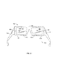
図5A、図5B、及び図6は、本開示の特徴による、データを受信し、伝送し、表示するための例示的システム400を示す。このシステム400は、着用可能な計算装置であり、上述した構成に含まれている部品と同じ多くの部品を含んでいる。図5に示した装置410は、ユーザの頭に着用可能なように構成されている。以下に詳述するように、装置410には、ユーザの頭に装置410をうまく着用できるようにするバンド412が含まれる。装置410には、バンド412の一部からディスプレイ端部416に伸び、ディスプレイエレメント454を含むエクステンションアーム414がさらに含まれている。エクステンションアーム414は、装置410をユーザが着用したとき、エクステンションアーム414に取り付けられたディスプレイ454がユーザの目の近くに配置され、少なくともその目の視線内にあって、ユーザが見ることができるように画像をディスプレイ454上に表示するよう構成されている。このようにして、エクステンションアーム414は、装置410の少なくとも1つの動作、すなわちユーザに画像を見せる動作を実行するよう構成されている。エクステンションアーム414を通じて別の動作も実行することが可能であり、装置の組立品410の制御機能又は装置の組立品410と接続され又は交信する他の電子装置の機能をユーザが実行できるように、ユーザが使うことのできるタッチ入力470の形状の入力装置を含むことができる。
FIGS. 5A, 5B, and 6 illustrate an
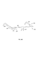
バンド412は図5に示されており、中央部430の両側から伸びるサイドアーム440A及び440Bを有する中央部430が含まれている。中央部430には、着用者の鼻に乗せるよう構成された鼻あて420が含まれ、中央部430から一様に伸びるか、あるいは少なくとも一様に伸びるようにみえるサイドアーム440A及び440B用の中央サポートが中央部430に設けられ、中央部430とサイドアーム440A及び440Bとの間の遷移領域には屈曲部又は曲線部が含まれている。ノーズブリッジ420には、中央部430から伸びる1対のブリッジアーム422を含めることができる。図5及び図6に示す装置の組立品410の実施の形態において、ブリッジアーム422は、中央部430から下方に伸びている。他の図に示すように、図5に示す装置の組立品410の向きは一般に、ユーザの頭が直立した中立位置にあるときにユーザが着用したときの装置410の向きに対応している。中央部430から下方に伸びているブリッジアーム422の説明は、このようなフレームに関して行われ、本記載のためになされている。他の相対的な方向についての説明もまた、同様の目的で行われ、明示的に記載されていない限り、本開示内容を限定することを目的とするものではない。
ブリッジアーム422には、着用者の鼻の部分に乗せる位置にパッド424を含むことができる。パッド424は、心地よくするためにアーム422より柔らかい素材で作ることができる。加えて、パッド424の素材は、ユーザの鼻の表面に沿って滑り落ちることを防ぐために、可塑性を有するか又はきめを持たせることができる。ブリッジアーム422は、さらに、ユーザの鼻に心地よく収まり又はつかまるような可塑性を持たせることができる。また、ブリッジアーム422は、パッド424の位置を変えてユーザに最もうまく適合するように、曲げること及び位置変更が可能であるようにすることができる。これには、お互いに近づけたり遠ざけたり中央部430から前方や後方へ動かしたりする動きが含まれ、中央部430の高さを調整することができ、従って、ユーザの目に対するエクステンションアーム414及び付属するディスプレイ454の位置を調整することができる。
The
ディスプレイ及びディスプレイに関する他の機構のさらなる調整は、エクステンションアーム414をバンド412に取り付けるための機構と同様に、上述の実施の形態と同じように行うことができる。他の実施の形態において、アーム及びパッドと同様な機構を中央部430に一体的に形成し、ユーザの鼻に接触するノーズブリッジ420の面積を図示した実施の形態と比べて大きくしたり小さくしたりすることができる。従って、装置410は、ユーザのこめかみ越えて耳の上に伸びるサイドアーム440A及び440Bとともに、鼻あて420がユーザの鼻に乗るようにユーザの頭に着用することができる。以下に述べるように、ブリッジアーム422の調整又は他の調整により、ディスプレイエレメント454が、ユーザの一方の目から見て適切に配置されるように、装置420は構成される。1つの配置において、ユーザの視野範囲に位置するようディスプレイ454を配置するが、ディスプレイ上の画像をすべて見るためにはユーザは目を上方に向けなければならないようにブリッジアーム422を調整して、装置410をユーザの頭に配置することができる。
Further adjustments of the display and other mechanisms relating to the display can be made in the same manner as in the above-described embodiment, as well as the mechanism for attaching the
サイドアーム440A及び440Bは、ユーザのこめかみに沿って又は耳の領域でユーザの頭と接するように構成することができる。サイドアーム440A及び440Bには、中央部430に向かい合ってそれぞれの自由端部444が含まれる。自由端部444は、装置410を着用したとき、ユーザの耳の近くになるよう位置決めすることができる。図5及び図6に示すように、中央部430とサイドアーム440A及び440Bとは、概ね「U」字型とすることができる。この例では、U字型は非対称である。非対称であるのは、1つは、サイドアーム440A及び440Bの自由端部444A及び444Bが異なる構成となっているためである。図示のとおり、自由端部444Aは、回路及び/又はシステム400への電源(例えば、取り外し可能な又は充電可能なバッテリー)を収納することができるよう大きくすることができる。2つの自由端部の構成を、自由端部444Bが回路及び/又は電源装置を収納するように、切り替えてもよい。
大きくした自由端部444Aは、エクステンションアーム414にバランシングウェイトを置くよう構成し配置することができる。エクステンションアーム414は、ユーザの耳の前に位置するので、その重量の一部はユーザの額で支えられることになる。ユーザの耳の後ろに耳づる446の形状で重りを加えることにより(または重量の一部をユーザの耳の後ろに移すことにより)、耳が支点となって、エクステンションアーム414の重量が耳づる446の重量と釣り合う。これにより、ユーザの鼻にかかる重量は幾分少なくなり、快適さが増し、ユーザの鼻で下向きに鼻あて420がずり落ちる可能性を減らし、より適合させることができる。大きくした自由端部444Aにあるバッテリー又は種々の制御回路のような部品は、装置410に好ましい重量分布を与えるように配置することができる。例えば、バッテリーのような重い部品は、重量分布を調整するために、サイドアーム440Aのエクステンションアーム414に向かって又は離れて配置することができる。1つの実施の形態において、重量の大部分は、ユーザの耳で支えられるようにするが、装置に安定感を与え、ディスプレイ454を好ましい位置に維持するために中央部430を額の好ましい位置に保持するために、重量の一部は鼻により支えられるようにすることができる。1つの実施の形態において、装置の組立品410の55%と90%との間の重量がユーザの耳で支えられるようにすることができる。
The enlarged
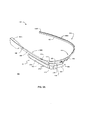
バンド412は、適切な力をかけて様々な大きさのユーザの頭に合うように、十分な範囲で弾性的に変形するよう構成することができる。1つの実施例では、バンド412は、成人の頭の少なくとも90%に快適に確実に適合するよう作られる。このことを達成するために、図9に示したように、バンド412は、自由端部444A及び444B同士の間隔496が最初に加えられた力により大きくすることができるか、あるいは、少なくとも40%の縮められない間隔4961から50%までの縮められる間隔4962までにするように、塑性的に変形(または弾性的に変形)するよう構成することができる。他の実施例では、間隔4961は50%以上に広げることができる。自由端部444A及び444B同士の元の間隔4961は、小さい頭の大きさのユーザが着用したときでも、自由端部444A及び444B同士の間隔が縮まることによりユーザの頭の側部を圧迫するように、間隔496が少なくとも少しだけ(例えば、約5%)増えるよう、バンド412の長さを最も小さい頭より少し小さくなるよう構成することができる。
The
加えて、バンド412は、バンド412が比較的頭の大きいユーザに合うよう引き延ばされた時、ユーザの頭の側部に加わる圧力が、着用したときに痛みを感じさせるほど、あるいは装置410の着脱が難しくなるほど大きくならないような適切なばね定数とする構成とするような、構造とすることができる。バンド412に好ましい収縮特性を与えるように、別の形状で、確かな特性を有する別の素材を用いることができる。1つの実施例において、バンド412は、上述のように、約0.005N/mmと0.02N/mmとの間のばね定数を持ち、他の例では、約1/100N/mmのばね定数を持つことができる。上述の例示によるばね定数が与えられた場合、バンド412は、約0.3Nと1.2Nとの間の力により元の間隔である約156mmから約216mmに広がることになる。別の例では、このような拡張は、約0.6Nで生じる。
In addition, when the
バンド412には、柔軟な内側部438と弾力性のある外側部448とを含めるよう構成することができる。内側部438には、バンド412の、ユーザの頭と接触するようになっている部分を含めることができる。図示した特定の実施の形態において、内側部438は、バンド412の、ユーザの頭と接触する領域のいかんにかかわらず、内側部の柔軟な素材によりユーザの頭に確実に接触するように、バンド412の内側面全体を特徴づけることができる。内側部438は、ユーザの頭にバンド412をより快適に装着できるようにする一方、全体的な形状を保持することができるような、どのような素材で作ることもできる。可能性のある素材として、フォームラバー、ネオプレン、天然又は人造皮革、及び、種々の織物のような、様々なものが含まれる。1つの実施の形態において、内側部430は、射出成型したTPEで作られる。内側部430はまた、例えば、グリルアミドTR90のようなポリアミドナイロンを含む、種々のナイロンで作ることもできる。内側部430の素材の柔軟性は素材のデュロメーターにより測定することができる。1つの実施例では、内側部438は、30と70との間のデュロメーター硬さを有するTPEで作ることができる。内側部438はまた、内側面439の反対側に、空洞になった通路又はチャンネルを有するように作ることもできる。このような通路又はチャンネルは、エクステンションアーム414と結び付いた配線のルートとして用いることができる。例えば、上述のとおり、電源を供給するためにエクステンションアーム414の内部部品と接続することができるバンド412の大きくした自由端部444Aにバッテリーを収納することができる。この接続は、内側部438を通るチャンネル又は空洞になった通路を通して配線することで行うことができる。
The
バンド412の外側部448は、金属やプラスチックのような弾性的に柔軟性のある素材で作ることができる。一般に、このような素材の特性は、バンド412が伸びてユーザの頭に取り付けることができるような柔軟性を持ち、ユーザの頭にバンド412を保持するために快適な力を加える一方、外側部448は、バンド412を好ましい形状に保持するようにできる。外側部448は、バンド412の形状が大きな頭を持つユーザが着用するだけで、永久的に変形することのないような、十分高い限界値まで、弾性的に変形させることができる。外側部448として可能性のある素材には、アルミニウム、ニッケル、チタン(等級5のチタニウムを含む)、種々の鋼鉄(スプリングスチール、ステンレススチール、等を含む)、又は、これらや他の金属を含む合金のような金属が含まれる。他の実施例において、外側部448又は内側部438は、炭素繊維強化ポリマー(CFRP)のような、合成素材で形成することができる。外側部448の厚さは、好ましい柔軟性を持たせるために素材に応じて調整することができる。1つの実施例では、バンド412についての好ましい装着特性及び柔軟性は、外側部448に約0.8mmと1.8mmとの間の厚さを持つ等級5のチタニウムを用いることで達成できる。
The
内側部438は、外側部448により形成されたチャンネル内に少なくとも部分的に収まるような外形を持たせることができる。1つの実施例では、内側部438は、外側部548の概ねU字型の断面形状で形成されたチャンネル内に収まるような大きさとすることができる。このようなチャンネルは、バンド412の配線を収納するよう、又は、そのような配線を保持するために、内側部439に形成した部分的に解放されたチャンネルに閉じ込めるように、構成することができる。
The
図5に示すように、サイドアーム440Aには、ユーザの耳の後部に沿って曲がるようなアーチ型部又は曲げ部を含めることができる。眼鏡と一緒のときは、曲がりの大きさ、耳の周りに伸びる長さ、及び、もしあれば、実際に耳の外側で保持される接触量を含んで、このような曲げ部の特定の形状は様々に変えることができる。サイドアーム440A中の屈曲部446は、大きくした自由端部444Aの連続的形状に融合することができ、この大きくした自由端部444Aが直近の耳の後ろのユーザの頭の部分に接触するような位置とすることができるような構成とすることができる。屈曲部446は、異なる大きさや形の頭でも適切に着用できるように、弾性的に変形させることができる。このような実施例において、大きくした自由端部444Aは、内側部438と一体化して形成することができ、外側部448を超えて伸びる部分に内部サポートを含めることができる。このような内部サポートには、バッテリーや装置410につながる電気回路を収納することができる内部エレクトロニクスハウジングを含めることができる。この内部サポートにはまた、バンド412を曲げて着用者の頭に保持圧を加えるスプリング要素(不図示)のような弾力性のある部材を含めることができる。このようなスプリング要素は、ユーザが大きくした自由端部444Aの位置を調整することができるように、可塑的に変形することができる。骨組みワイヤを、このような特性を持たせるために用いることができる。大きくした自由端部444A内の内部サポートを、外側部448内にある内側部438の領域に伸ばし、付加的なサポートを行うことができる。
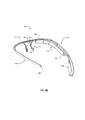
As shown in FIG. 5, the
エクステンションアーム414には、サイドアーム440Aに沿うようにして、バンドに沿って形成され伸びている第1の部分476でバンド412から下方に伸びている第1の部分476が含まれる。第1の部分476は、さらに、バンド412から離れて第1の部分476とジョイント456で接続されているエルボー部分450まで伸びるよう形成されている。エルボー部分450は、ジョイント456を中心としてエルボー部分450を回転させて調整することができるアーム476に対し角度をもたせてディスプレイ454を支える。図5に示した実施例において、エクステンションアーム414の第1の部分476は、サイドアーム440Aの少し曲がった部分に沿って伸ばすことができるように、同じように少し曲げることができる。このような曲がりは、サイドアーム440Aが中央部へ移行するにつれてバンド412が内側に曲がるのと同様に、エクステンションアームに続けてゆくことができる。エクステンションアーム414は、ディスプレイ454がユーザから見えている間ユーザの視線の外にバンド412を維持することができるように、垂直方向にバンド412の下部に位置することができる。
The
装置410は、バンド412とエクステンションアーム414とが識別可能な要素となるような視覚的外見を持たせるよう構成することができる一方、エクステンションアーム414を、バンド412の少なくとも一部として形成することもできる。例えば、バンドの構成において、バンド412には内側部438と外側部448とが含まれ、エクステンションアームハウジング452は、図10に示すように、内側部438に一体的に形成することができる。このような実施例において、回路基板、ロジック基板、その他のようなエクステンションアーム414の内部部品は、ハウジング452の関連部分として、内側部438にまで伸ばすことができる。
別の実施例において、エクステンションアーム414のハウジング452は、内部部材などにより、大きくした自由端部444Aの内部のハウジングユニットに結合させることができる。この内部部材は、固着要素、接着剤、又は一体成形を用いるなどして2つを結合することができる。そして、ハウジング452、内部のハウジングユニット、及び結合部は、実質的に一様な外見になるようにし、バンド412の内側部438の可視部分を形成するために、TPEその他のような別の素材でオーバーモールドすることができる。分割線、平削り傷、等の視覚的特徴は、必要なら別の要素の視覚的外見を定めるために、このようなユニット432の形に含めることができる。
In another embodiment, the
1つの実施例において、バンド412は、概ね柔軟性のないエクステンションアーム414の一部に沿って一体的に形成されるか又はエクステンションアーム414の一部に結合されており、バンド412は柔軟に作られているが、エクステンションアーム414に取り付けられる部分は柔軟性がないような作りにすることができる。図示の実施例において、これは、サイドアーム440Aの一部で生じる。このような実施例では、柔軟な部分が、一般的に上述したように、中央部430で生じ、あるいは、中央部430とサイドアーム440A及び440Bとの移行領域で生じるように、バンド412を形成することが好ましいことがある。
In one embodiment, the
このような構成は数々の方法で達成することができる。例えば、サイドアーム440Aを、柔軟性のないエクステンションアーム414に結合することにより、より硬くすることができる。このような実施の形態において、サイドアーム440A及び440Bがユーザの頭に同様の感覚を与えるように、サイドアーム440Bも硬くすることが好ましいかもしれない。これは、内側部538の内側の硬いワイヤ等のような、構造部材を組み込むことにより達成することができる。さらに、外側部分448は、サイドアーム440A及び440Bがもっと硬くなるような構造とすることができる。例えば、外側部分448は、外側壁459に対して内側に伸びる壁480とともに、U字型の断面形状を持つことができる。壁480は、サイドアーム440A及び440Bに沿って生じ、中央部430が硬くならないように中央部430で無くなるか又は少量が内部に伸びるようにすることができる。さらに、図6に示すように、外側部分448を含むバンド412は、外側壁459が中央部430の真ん中に向けて狭くなるように先細にすることができる。加えて、外側部分448の素材の厚さは、中央部に相対的により柔軟性を持たせるために、バンド412の中央部430に沿って薄くすることができる。
Such a configuration can be achieved in a number of ways. For example, the
概ねディスプレイ軸を定める細長いディスプレイ454は、ジョイント456を中心としてエルボー部分450を第1の部分476に対して相対的に回転させて、第1の部分476に対して、例えば、約100°から約125°の範囲内で調整することができる角度で伸びることができる。第1の部分476の形状は、測定した角度の方向に向くような曲がりを有するように図に示されているが、このような測定は、ジョイント456に向かう端部に沿って、第1の部分の一部に接するような直線について行うことができる。他の実施例では、ディスプレイ454の角の調整は、約20°の範囲内、又は約16°以下の範囲内で行うことができ、エクステンションアーム414の第1の部分476に対して相対的に約195°から約115°の範囲の位置のような、中央位置にすることができる。ジョイント456は、ユーザが着用したときエクステンションアーム414が実質的に垂直な軸に沿って回転することができるようなエクステンションアーム414内の位置にある。言い換えれば、実施の形態に示したように、バンド412は、概して平面をなすU字形で形成される。このような平面は、バンド412の他の部分に対して相対的に垂直に変位させてバンド412を曲げることができるように、概略的なものであると考えることができる。ジョイント456は、エルボー部分450が実質的に平行な他の面又は同一の面に沿って回転することができるよう構成することができる。
An
図7及び図8に示すように、ディスプレイ上に表示された画像を装置410の着用者が快適に見ることができるような、ディスプレイ454の位置決めを行うために、このような調整を行うことができる。図示のとおり、軸492を中心としてエルボー部分450を回転することで、面460をユーザの目490に近づけたり遠ざけたりすることができる。これにより、ユーザはディスプレイに表示される画像を快適に見るためにディスプレイ454を調整することができ、ディスプレイ454が、例えば、ユーザの眉やまつ毛に当たらないような距離に位置決めすることができる。さらに、特定のアプリケーションでディスプレイ454のいくつかの形状において、ユーザの目が中立位置(すなわち、前方を見ている位置)にあるとき、面460の内側端部462がユーザの瞳491の外側に位置するよう、ユーザがディスプレイ454の横の位置を調節できるようにすることが望ましいことがある。
As shown in FIGS. 7 and 8, such adjustments may be made to position the
図8に示すように、装置410を着用したとき、ディスプレイ454’は、着用者の瞳491の外側端(線494で示す)を少なくとも部分的に越えて伸びるように、位置決めすることができる。ジョイント456により、外側に目490から離れる方向にディスプレイ454が動いている間、ユーザの目490が図8に示す中立位置にあるとき、ユーザの瞳の外側に端部462が動くように、ディスプレイ454も横方向成分に沿ってある距離498だけ動く。
As shown in FIG. 8, when the
加えて、第1の部分476と結合しているバンド412を曲げることに起因して生じる中央部430又は鼻あて420に対する相対的な第1の部分476の動きを、エルボー部分450と第1の部分476との間の調整により調整することができる。従って、これにより、エクステンションアーム414の第1の部分476を同じように回転させ移動させる。このような動きにより、エクステンションアーム414の形状に応じて、エルボー部分450及びディスプレイ454に対応する回転と移動を生じさせる。ディスプレイが中央部430に近づき、それによりユーザの目に近づくような、バンド412及び/又はエクステンションアーム414の他の構成も可能である。
In addition, the movement of the
バンド412を曲げることによる、ディスプレイ454の回転と移動により、上述したように、ユーザの目に近づきすぎたり、あるいは、端部462がユーザの瞳490と並んだり内側になったりするような不都合な位置に動くことがある。このような場合、バンド412を曲げることによる動きに逆らいディスプレイ454を適切な位置に動かすために、エルボー部分450を、ジョイント456を中心に回転することができる
第1の部分476とエルボー部分450とのジョイント456には、エルボー部分450が第1の部分476に対して相対的なある位置に保持することができる摩擦力を有する内部ヒンジを含むことができる。第1の部分476及びエルボー部分450は、図に示すように一様な外見となるよう構成することができる。第1の部分476及びエルボー部分450は、さらに、エクステンションアーム414の外側面475の湾曲がジョイント456の位置にかかわらず外見が一定となるよう構成することができる。さらに、図11に示すように、第1の部分476の関節面464Aは、外側表面453により前縁466を画定することができる。関節面464Aは、頂部が外縁よりエルボー部分450と重なるようななめらかな曲線を持つ外見となるよう、外側面475と交わるように構成することができる。このような構成とすることで、仮に、関節面が簡単な回転面であれば、エクステンションアーム414の曲がった外側面475で関節面がもっと波打った交差部を形成していたのに比べ、視覚的に快適で一様な外見を得ることができる。関節面464Bは、面453に隣接した2つの軸に沿って出っ張っている面から、1つの軸に沿って出っ張り他の軸に沿って真っすぐな面に移動するものとして示されている。関節面464Aは、関節面464Bの陰画像とすることができ、前縁466を好ましい外見とすることを容易にする。
By rotating and moving the
他の機構は、ユーザの瞳491の外側に端部462が位置することができるように横方向の平行移動による調整を行うために用いることができる。例えば、ディスプレイ454は、好ましい横方向への移動を可能にするスライド機能を用いてエクステンションアーム414の第1の部分476に取り付けることができる。これは、トラック又は他のスライドジョイントを用いてエクステンションアーム414の第2の部分450を第1の部分476に結合することにより達成することができる。目を休めるためにユーザの目に向け又はユーザの目からディスプレイ454を動かすために、追加のスライド機能または望遠機能を用いることができる。他の構成では、エクステンションアーム414は、ジョイント456のない単一の機構とすることができ、図8に示した第2の部分450の回転面と同様の面で回転するようにバンド412に回転可能に取り付けることができる。このような回転は、従って、ディスプレイ454及び端部462好ましい横方向への調整のための横方向成分も有する。
Other mechanisms can be used to make lateral translational adjustments so that the end 462 can be located outside the user's pupil 491. For example, the
1つの実施の形態において、ディスプレイ454に関する画像ソース及び関連する回路は、エルボー部分450に保持することができる。タッチ入力470の回路は、ディスプレイ454がユーザの目の前に配置された時、第1の部分476がこの目の近傍のユーザのテンプルを覆って伸びる位置に配置されるように、第1の部分476に配置することができる。
In one embodiment, the image source and associated circuitry for
図示の実施の形態において、ディスプレイ454は、ハウジング452内に位置する電子ディスプレイ要素に、生成した画像をユーザの見ている光景にかぶせるかあるいは結合するように構成された概ね透明なプリズムで形成される。このようなプリズムは、受信側458に投影された画像を受け取り、ディスプレイ454の視界側460を見ることによりユーザが画像を見ることができるように組み立てることができる。これは、ディスプレイ454を特定の形にすること又はディスプレイ454の材質の特性により達成することができる。図示の例において、ディスプレイ454の受信側458は、ハウジング452に隣接して、又は、ハウジング452内の電子部品が望みのビデオ画像をプリズム454の受信側458に投影するよう構成したビデオプロジェクターを含むようにしたハウジング452内にある。このようなプロジェクターは、必要ならばプリズム454の適切な領域に画像の焦点を合わせるために、LCD、CRT、及びOLEDディスプレイのような画像ソース、及びレンズを含むことができる。ディスプレイ454に関連する電子部品は、受信したビデオ信号に基づき必要な画像をプロジェクターに生成させるための制御回路を含むこともできる。他の形式のディスプレイ及び画像ソースについても上述したが、エクステンションアーム414に組み込むことができる。さらに、ディスプレイは、例えば透明な基板からなるビデオスクリーンの形状とすることができる。このような例では、画像生成手段は、全体的にディスプレイが透明でないような、スクリーン直後に位置するLCDディスプレイ、CRTディスプレイ、その他への回路とすることができる。このような実施の形態では、画像生成手段を収容するために、エクステンションアーム414のハウジングはディスプレイ及び画像生成手段の後ろに伸ばすことができる。
In the illustrated embodiment, the
ディスプレイ454の受光面458は、装置の着用者の周囲の情景と投影した画像とを合体させるような構造となっている。これにより、ユーザは、周囲の環境とディスプレイプリズム454に投影された画像の両方を見ることができる。プリズム454及びディスプレイエレクトロニクスは、画像の種々の好ましい組み合わせを実現するように、不透明な又は半透明の画像、或いはその組み合わせによる構成とすることができる。
The light receiving surface 458 of the
図5の実施の形態では、着用したときユーザの右の眼の前に位置するようバンド412と結合したエクステンションアーム414が示されているが、鏡像関係になるエクステンションアーム414をバンド412の反対側に取り付け、ユーザの左目の前に配置するような類似の実施の形態も可能である。装置410のアプリケーションまたは個々のユーザの好みに応じて、エクステンションアーム414をユーザの頭の特定の側に配置することが好ましいであろう。例えば、右利きの人は、タッチ入力470を容易に行えるように頭の右側にエクステンションアーム414を置く方を選ぶことができる。他の実施例では、人は、ディスプレイ454に表示された要素と共に容易に動作させることができるようにディスプレイ454を利き目の方に置く方を選び、或いは、他の動作を行うときに、ディスプレイ454に表示された要素から容易に焦点を外すことができるように、ディスプレイ454を利き目でない方に置く方を選びことができる。
In the embodiment of FIG. 5, the
上述の通り、タッチ入力470の形式の入力装置も、エクステンションアーム414に含めることが好ましい。タッチ入力470は、他の可能性の中で、静電容量感知、抵抗感知、又は表面音波処理により、指の位置又は動きのうちの少なくとも1つを感知するように構成された、タッチパッドタイプの装置、又は、トラックパッドタイプの装置とすることができる。タッチ入力470はさらに、面に平行に又は平面的方向の指の動き、又は、面に垂直方向に、又はその両方向への指の動きを感知することができ、加えた力の大きさも感知できるようにすることもできる。タッチ入力470は、不透明な、又は、半透明な、又は、透明な、1以上の絶縁体の外層又は誘電体の外層、及び、不透明な、又は、半透明な、又は、透明な、1以上の導電層の内層を有するよう成形することができる。
As described above, an input device in the form of
1つの実施の形態において、タッチ入力470の外層はハウジング452の外壁453の一部をなすことができる。これにより、ハウジング452内にタッチ入力470を継ぎ目なしに、或いは、一様に組み込むことができる。ハウジングは、タッチ入力470の内層及び、制御回路のような関連する任意の電気的構造を収容するために内部に空洞を作ることができる。タッチ入力470の外層は、タッチ入力470の内層の大きさ、形、及び位置により定められるような、1つ以上のタッチ面470の形で、全面壁453又は選択された操作可能領域472を含むことができる。ハウジングの一部がタッチ入力470の外層として用いられる場合、ハウジング452はプラスチックのような誘電体で作ることができる。別の実施の形態では、タッチ入力は、ラップトップコンピュータのタッチパッドと同様なウインドウ又は壁453を通す開口内の操作領域を定めるために壁453とは別に、誘電体の外層を含むハウジング452の開口内に取り付けた別々の要素とすることができる。
In one embodiment, the outer layer of
図示の実施の形態において、タッチ入力470は、第1の部分476に位置し、ユーザの頭の側に横たわる概して垂直な平面を作る。曲がった外側面等を機能させるよう、回路を形成し調整することができる。従って、タッチ入力470は、着用したとき装置410のユーザから見えないかもしれない。
In the illustrated embodiment,
加えて、ハウジング452は、ロック機能又はスリープ機能を組み込み、又は装置410への電源のオン・オフ状態をユーザが切り替えることができるようにすることを含む追加機能をエクステンションアーム414に提供することができる、ボタン484(図5Bに示す)のような、追加入力機構を含むことができる。このボタン484は、オン又はオフ、又はスリープ又はアウェイクのような、装置の状態を表示することのできるLEDライトをその面の下にさらに含むことができる。このボタンは、オンのときライトをみることができるが、ライトがオフのときライトをみることができないように構成することができる。
In addition, the
タッチ入力470、又は、他の形式の入力は、内蔵型CPU、又は関連する着用可能な機器に取り付けたCPU、又は、スマートフォンやラップトップコンピュータのような遠隔装置のようなエクステンションアーム414により実行される制御機能を提供するために、用いることができる。1つの実施の形態において、制御機能に関する情報はディスプレイ454上でユーザが見ることができる。1つの実施例では、この制御機能はメニューアイテムで選択する。このような実施例では、選択肢のリストを記載したメニューをディスプレイ454上に表示することができる。ユーザはカーソルを動かすことができ、或いは、タッチ入力470に沿ってあらかじめ定めた指の動きによりハイライトした選択肢をスクロールすることができ、そして、別の動きにより選択を確定することができ、選択の承認はディスプレイに表示される。メニューアイテムの例には、遠隔からリンクしたスマートフォンの呼び出しに応えるか拒否するかの選択、或いは、ディスプレイ中の地図をスクロールするかズームインするかの選択を含めることができる。
エクステンションアーム414に追加の入力機構を含めることができる。追加の入力機構には、図5に示すようなカメラ426を含めることができる。カメラは、ユーザの自由裁量で、写真を撮るため又はビデオを記録するために用いることができる。真実味を増大させる機能を組み込むのに用いるために、ユーザが見る環境の画像を得るための装置としてカメラを用いることもできる。例えば、カメラ426と同じハウジング機構の中に光センサーを含めることができる。このような光センサーは、カメラ426に関連付けたファームウェア又はソフトウェアで用いることができる。図5に示すように、カメラ(及びセンサー)は、エルボー部分450内のハウジング452に収納し、ディスプレイ454の画面460に実質的に垂直な方向に向けることができる。このような構成において、カメラ426は、ユーザの視線の方向に向けるよう配置し、センサー428はカメラ426の視界内の光を感知するために配置する。
The
1つの実施の形態において、ボタン474は、装置410のカメラ426又はマルチカメラの1つを用いて、画像を捕えるために、ユーザからの入力を受け取り装置410へ送るよう構成することができる。1つの実施の形態において、装置410内の制御回路又は制御ソフトウェアにより、ユーザが画像を捕えるための、マルチカメラのうちの1つ又はいくつかを選択すること、又は、ユーザが選択したカメラを用いて実際に画像を捕えるために入力を受け取る前にボタン474を用いて「撮影する」ことができるようにすることができる。ボタン474は、ハウジング452の上部面467のエクステンションアーム414に配置することができる。このような配置により、例えば、上部面467の反対側に位置するユーザの親指を用いて、ユーザはハウジング452をつかむことができるようにすることができる。この動作は、従来のカメラ(例えば、自動露出カメラ又は一眼レフカメラ)のシャッターを動作させる動作、又は、ユーザにとって直感的な、ボタン474を用いてカメラ474で写真撮影を行う動作に似た人が行う動作と同様にすることができる。加えて、上述のはさむ動作により押圧するボタン474を配置することにより、ボタン474の操作が安定し、ボタン474を押す時、エクステンションアーム414をユーザの親指で支えることができる。このような安定性は、ボタン474に加える力を、画像を捕えるときにエクステンションアーム414を動かさないような十分小さな操作圧力とするようなボタン474の構成とすることで、さらに向上させることができる別の実施例では、ボタン474は、光スイッチ、静電容量型タッチスイッチ、圧力検出型抵抗スイッチ、その他のスイッチのような、どのようなスイッチとすることもできる。
In one embodiment, the
先に説明したように、ハウジング452はタッチ入力470用回路のような電子回路を含むことができる。加えて、ハウジング452は、ディスプレイ454、カメラ426、又はセンサー428と関連付けた画像ソースの制御回路、又はディスプレイ454、タッチ入力470を制御するための、又はエクステンションアーム414の他の機能を発揮させるためのプロセッサーを含む回路基板を含むことができる。ハウジング452は、他の回路に電力を供給するバッテリーのような、電源をさらに含むことができる。加えて、ハウジング452は、メモリー、マイクロプロセッサー、又は、遠隔装置と接続するための携帯電話回路、短距離無線回路(例えば、ブルートゥース)、又は、WiFi回路のような、通信装置を含むことができる。加えて、このような回路を、少なくとも1つの大きくした自由端部444Aの中のような、バンド414中の、例えばその内部の空洞の中に、含めることができる。
As previously described, the
大きくした自由端部444Aはまた、バッテリーを取り外すことなくバッテリーを再充電するために装置410を電源に接続するために用いることのできる1つ以上の接続口482を含むことができる。さらに、装置410は、スマートフォンやコンピュータのような外部装置に装置410を接続するために用いることのできる接続口480を含むことができる。接続口480は、USB、ファイヤーワイヤー、サンダーボルト、又は、専用接続口480のような、標準的などのような接続形式とすることもできる。接続口480は、装置410内のバッテリーを再充電するために電源と接続するよう構成することもできる。
The enlarged
上述のように、装置410の実施の形態において、図10に示すように、エクステンションアーム414は、サイドアーム440Aの大きくした自由端部444Aを含むバンド412の内側部438の一部とともにユニット432に含めることができる。このような実施の形態において、取り外し可能なバンド4121は、内側部4381の残りと外側部4481のすべてを含むことができる。バンド4121がモジュール432に組み込まれた時、結果できあがった機構は実質的に図1〜図9に関して先に説明したものと同じとすることができる。さらに、追加のバンド4122は、バンド4121と同様に、内側部4382及び外側部4482を含むことを条件とすることができる。バンド4122は、しかしながら、1対のレンズ4182のそれぞれを収納する、バンドと一体的に形成された1対のリムを含む構造とすることができる。レンズ4182は、サングラスレンズ、処方箋による眼鏡レンズ、処方箋によるサングラスレンズ、等の形態とすることができる。レンズ4182は、リム4312内で、外側部4482と内側部4382との間の部分に保持することができる。バンド4122の内側部4482は、レンズ4182をバンド4122と交換ができるように取り外し可能とすることができる。内側部4382もまた、内側部に一体的に形成した鼻あて4202を含むことができる。モジュール432は、サングラスレンズを含むバンド4122がモジュール432を調整できるよう組み立てられている時、例えば、ディスプレイ454の明るさのようなものを一致させるための機構その他の手段を含むことができる。
As described above, in the embodiment of the
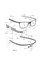
他の実施の形態によれば、図12A及び図12Bに示す通り、ノーズブリッジ420はバンド412の中央部430から取り外し可能にすることができる。図12Aはバンド412から取り外したノーズブリッジ420を示し、図12Bはバンド412に取り付けたノーズブリッジ420を示す。この実施例において、ノーズブリッジ420は、バンド412の連結部486に取り外し可能に取り付けることのできる横材485を含むことができる。連結部486は、中央部430から切り取った部分であり、1つの実施例では、横材485と嵌合する溝、スリット、又はチャンネルを有することができる。他の実施例では、連結部486は、横材485と嵌合するように構成した中央部430からの突出部とすることができる。さらに他の実施例では、連結部486は、バンド412の残りの部分と視覚的な差異はないが、横材485の内又は外にある対応する磁石と相互に作用するよう構成された磁石のようなものを埋め込むことができる。
According to other embodiments, the
ノーズブリッジ420はまた横材485と結合することのできる2つのフレーム487を含むこともできる。ノーズブリッジ420はさらに、フレーム487に合致するレンズ488を含むことができる。レンズ488は、任意の方法でフレーム487に収めることができ、1つの実施例では、フレーム487の内面に形成したチャンネル内に固定することができる。フレーム487は、フレーム487、レンズ488、及びブリッジアーム422及びパッド424を含む、ノーズブリッジ420をユーザが取り外すことができるように、横材485とともに一体的に形成することができる。ノーズブリッジ420は2つのフレーム487を含むよう描かれているが、レンズ488は、直接横材485に取り付けてもよい。このようにして、接合、接着、ねじのような機械的留め具、その他のような任意の方法で、各レンズの端部を横材485に取り付けることができる。
The
横材485は、本開示の種々の特徴に従い、異なる方法で連結部486に取り付け、取り外しを行うことができる。1つの実施例では、横材485はリーフスプリングとしての機能を有することができる。この場合、ユーザは横材485を連結部486の受容部にはめ込むときに横材485の端部を内側にたわめることができる。連結部486からの取り外しは、受容部から端部を外すために、横材485の中央部を連結部486から引き抜くことにより行うことができる。他の実施例では、横材485はねじ又は他の形式の留め具で連結部486に固定することができる。さらに他の実施形態では、横材485及び連結部486の各々には、少なくとも部分的にその中に又はその表面に磁石を埋め込むことができる。磁石間の引力は、横材485を連結部486に固定するのに十分な強さとするが、過剰な力を加えないでもユーザがノーズブリッジ420を取り外すことができるようなものとする。
The crosspiece 485 can be attached to and removed from the connection 486 in different ways in accordance with various features of the present disclosure. In one embodiment, the cross member 485 can function as a leaf spring. In this case, the user can bend the end portion of the cross member 485 inward when the cross member 485 is fitted into the receiving portion of the connecting portion 486. Removal from the connecting portion 486 can be performed by pulling out the central portion of the cross member 485 from the connecting portion 486 in order to remove the end portion from the receiving portion. In other embodiments, the crosspiece 485 can be secured to the connection 486 with screws or other types of fasteners. In still other embodiments, each of the cross member 485 and the connecting portion 486 can be at least partially embedded with a magnet therein or on the surface thereof. The attractive force between the magnets is strong enough to fix the cross member 485 to the connecting portion 486, but the user can remove the
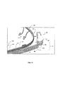
ノーズブリッジ420は、単一のユニットとして描かれているが、フレーム487の各々は、フレーム487が連結部486から別々に取り外すことができるように、それぞれ横材485を含むことができることがわかる。また、近視や遠視のような、あらゆるタイプの目の病気又は異常に対する処方箋によるレンズのような、人の目に適したあらゆるタイプのレンズとすることができることがわかる。レンズ488はまた、2重焦点レンズ又は読書用眼鏡、又はまぶしさを低減するためのフィルムを張り付けたものを含むこともできる。他の実施例では、レンズ488はサングラスとすることができ、また、紫外線A又は紫外線Bのような電磁波が人の目に入るのを少なくとも部分的に阻止することができる。さらに他の実施例では、レンズ488は全く装飾的なものとすることができ、ユーザの視力の矯正を行わないようにすることができる。多数のレンズの例を上述したが、レンズ488は、運動競技中にユーザを保護する運動競技用レンズ、材木店又は化学実験室での、物理的又は化学的影響からユーザを保護する保護レンズ、あるいは、例えば、紫外線又は赤外線を含む、特定のタイプの電磁波を取り除くような、特定の電磁波を遮蔽する特性を有するレンズのような、あらゆる他のタイプのレンズとすることができることがわかる。他の実施形態によれば、ノーズブリッジ420は、図13A、図13B、及び図13Cに示すように、永久的又は半永久的又は一体的にバンド412の中央部430に形成することができ、レンズ488は、ブリッジアーム422に取り外し可能に固定することができる。レンズ488は、クリップ489によりバンド412に取り外し可能に固定することができる。クリップ489は、レンズのどの面に形成することもでき、1つの例ではユーザの目に直面するレンズ488の面に形成することができる。他の実施例では、クリップ489は、レンズ488の端部面に沿って形成することができる。本開示による種々の特徴によれば、クリップ489は、種々の方法でブリッジアーム422に取り外し可能に固定することができる。1つの実施例では、クリップ489は、ブリッジアーム422の内側部分、例えば、ブリッジアーム422の間、に固定することができる。このようにして、ブリッジアーム422は、ブリッジアーム422が横方向に少し動かすことができるような、弾力性のある特性を持つことができる。ブリッジアーム422は、相互に離れるように動かすことができ、クリップ489は、ブリッジアーム422の間のこの動かした位置にずらすことができる。ブリッジアーム422を解放することで、クリップ489の横方向の力により、又はその逃げ溝を通すことにより、ブリッジアーム422の弾性力でレンズ488を所定の場所に固定することができる。この構成は図13Bに示されている。
Although the
もう一つの方法として、クリップ489をブリッジアーム422の外側部、例えば、隣接するブリッジアーム422から離れる方向に面する部分、に固定することができる。上述のように、ブリッジアーム422は横方向に弾性力を働かせる。この実施形態では、ブリッジアーム422は、方向に近づく方向に手動で動かされ、クリップ489はブリッジアーム422外側部分にずらすことができる。ブリッジアーム422を解放することで、ブリッジアーム422とクリップ489との間の横方向の力によりレンズ488を安定的に固定する。
Alternatively, the
レンズ488は、図13A及び図13Bに示すように、一体型として描かれているが、図13Cに示すように、別々の形とすることもできる。この例では、2つのレンズ488の各々にはクリップ489が含まれる。クリップの各々は、レンズの各々がノーズブリッジ420に固定されるように対応するブリッジアーム422に確実に固定することができる。このように、クリップ489は本開示の種々の特徴により、ブリッジアーム422に機械的に固定することができる。例えば、クリップ489をブリッジアーム422に動かないように固定するような、ブリッジアーム422に応じた機能をクリップ489はもつことができる。1つの実施例では、ブリッジアーム422は、クリップ489に応じた、スロット又はチャンネル又は角を有することができる。別の実施例では、クリップ489はブリッジアーム422の狭い部分に滑り込ませブリッジアーム422の厚い部分へと動かし、確実に固定することができる。上述のクリップ489をブリッジアーム422に固定する方法に加えて、クリップ489をブリッジアーム422に固定する他の方法を用いることもできる。例えば、フックや磁石部材やその他の固定機能を用いることができる。
Although the
加えて、一体型のレンズの実施形態又は独立型のレンズ実施形態の両方について上述した固定方法はブリッジアーム422の弾力特性を利用するものであるが、ブリッジアーム422の弾力特性に頼らない固定方法を使うこともできる。例えば、ノーズパッド424レンズ488又はフレーム487の一方に一体的に形成し、レンズ488又はフレーム487はーズパッド424と同時に取り外すようにすることができる。
In addition, the fixing method described above for both the integral lens embodiment and the stand-alone lens embodiment utilizes the elasticity characteristics of the
他の実施の形態によれば、装置410は、ユーザに対するディスプレイの解像度を維持しながら、近視(近眼)を矯正するマルチ‐レンズ構成を含むことができる。例えば、ディスプレイ454は、特定の構成及び実施の形態に基づき2mから無限大までの間の焦点距離とすることができる。この範囲の焦点距離に対して、近視の人は目とディスプレイとの間に矯正レンズがなければディスプレイ454をはっきり見ることができない。本開示の特徴によるレンズの上面図である図14に示すように、装置410は目490の近視度を矯正するために、ディスプレイ454と協働する複数のレンズ488a〜488cを含むことができる。レンズ488a及び488bは、装置410を着用したとき、人の目から見て、共にディスプレイ454とほぼ同じ外形を有するレンズとすることができる。レンズ488a及び488bは、ユーザの近視の度により変更することができる。例えば、少しの近視の度であれば、レンズ488aは比較的薄く、そして約−1.00ジオプトリーの処方とすることができる。近視のもっと深刻な場合、レンズ488aは厚くなり、ジオプトリーの負の強度が大きな処方、例えば、−1.00ジオプトリー以上、となることがある。近視の場合、レンズ488bは、レンズ488bの処方と反対の処方とすることができる。例えば、レンズ488が−1.00ジオプトリーの処方を有する場合、レンズ488は+1.00ジオプトリーの処方を有することができる。この実施形態において、ディスプレイ454は、レンズ488aとレンズ488bとの間に位置することができる。これにより、ユーザディスプレイ454から提供される映写をはっきり見ることができる。次にレンズ488cは、レンズ488a及び488b及びディスプレイ454に比べて目から最も遠くに位置することができる。このようにして、レンズ488cは、レンズ488aと同様にしてユーザの処方に対応することができる。レンズ488cは、レンズ488cがユーザの全体的な視力を矯正するためのものであり、ディスプレイ454の映写のためだけのものではないので、図12A及び図12Bに示すレンズ488のように楕円形とすることができ、ディスプレイ454のサイズや大きさに限定されることはない。
According to other embodiments, the
レンズ488a及び488bは、図15に示すように、レンズ488a及び488bがディスプレイ454に同時に取り付け及び取り外しができるように、スリーブ493の形に組み合わせることができる。この例では、スリーブ493は、サポート面495と共にレンズ488a及び488bを含むことができる。サポート面495は、プラスチックその他を含むポリマーのような、どのような素材でも形成することができる。1つの例では、サポート面495は、バンド412と同じ素材で形成することができる。レンズ488a及び488bは、スリーブ493をディスプレイエレメント454にかぶせレンズ488a及び488bによる視力矯正ができるようにするために、少なくとも1つの開口を形成して一定の距離だけ離してサポート面の間に固定することができる。このようにして、ディスプレイエレメント454は、レンズ488a及び488bの間及びサポート面495の間の開口497内に取り付けられる。図15でスリーブ493は2つの開口を持つよう描かれているが、スリーブは、スリーブが1つの開口しか持たないよう2つの面495の間をつなぐ追加面を含むことができる。レンズ488a及び488bは、接合、接着、機械的留め具、その他、のような既知の任意の取り付け方法で面495に固定することができる。先に説明したとおり、レンズ488a及び488bの処方箋は、上述の処方箋のような、ユーザの視覚障害を矯正して、ディスプレイ454を良く見えるようにするどのような処方箋とすることもできる。
The
別の実施例では、レンズ488a及び488bのうちの1つ又は両方を、過剰な太陽光からの保護のために傾けることができる。このように、レンズ488a及び488bは、フォトクロミックコーティングをレンズ面に施すことを含むことができ、あるいは、もう一つの方法として、レンズそのものを染色又は着色することができる。また別の実施例において、ディスプレイ454のみならずレンズ488a及び488bのうちの1つ又は両方を任意の方向に偏光させることができる。例えば、レンズ488bは、ディスプレイ454に生じる画像のコントラストを改善するために偏光させることができる。さらなる実施例において、ディスプレイ454及びレンズ488bの両方ともスリーブ495をディスプレイ454にかぶせる方向と垂直に偏光させることができる。偏光は、さらに、偏光位相の約半分に等しい距離だけスリーブ495をディスプレイ454にかぶせることにより、ディスプレイ454の全体的な外見が透明から不透明に変化するように構成することができる。このように不透明にする構成により、ユーザは、必要なときのみ、ディスプレイ454に表示された画像を見ることができるようにすることができる。レンズを染色又は着色することを含む上記実施例において、レンズ488a及び488bは、処方箋によるレンズ又は処方箋によらないレンズの任意の組み合わせを含むことができる。
In another example, one or both of
別の実施形態において、レンズ488a及び488bは、ディスプレイ454に一体的に形成することができ、あるいは、もう一つの方法として取り外し可能に固定することができる。レンズ488a〜488c及びディスプレイ454は、図1で隣接するように描かれているが、これらは必要な任意の隙間を介して構成することができることが分かる。このように、レンズ488a及び488bのいくつかは、ディスプレイ454に隣接する一方、いくつかは隙間を介することができる。レンズ488cも、他のレンズ488a及び488bのいずれかと隙間を介することができ、及び、もう一つの方法としてレンズ488a及び488bのいずれか一方と直接的に隣接するようにすることができる。
In another embodiment, the
代替的実施形態において、レンズ488a及び488bを使わず、レンズ488cのみを、ユーザの目490に対してディスプレイ454の反対向きに配置することができる。このような実施形態では、遠視のユーザは、レンズ488a及び488bを追加することなくディスプレイ454の映写をよく見ることができる。
In an alternative embodiment,
さらに他の実施形態において、レンズ488cは、レンズ部分をユーザの処方箋により、レンズの他の部分をディスプレイ454に対応させた、累進レンズとすることもできる。例えば、レンズ488cは、ユーザが装置410を着用したとき、ディスプレイ454の全体的外形に対応する部分を含むことができる。この部分は、視覚異常を矯正するための任意のジオプトリー測定形式による矯正レンズの1つ以上の層を含むことができる。
In yet another embodiment, the lens 488c may be a progressive lens with the lens portion corresponding to the user's prescription and the other portion of the lens corresponding to the
本発明は特定の実施の形態を参照して記載したが、当然のことながらこれらの実施の形態は、本願に開示した原理及び応用例を単に示しただけのものである。従って、当然のことながら、添付特許請求の範囲で定義した本願に開示した精神及び技術的範囲から離れることなく、図示した実施の形態その他の構成に対して多くの変更を加えることができ、他の構成を修正することもできる。 Although the invention has been described with reference to particular embodiments, it is to be understood that these embodiments are merely illustrative of the principles and applications disclosed herein. Accordingly, it will be appreciated that many changes may be made to the illustrated embodiments and other arrangements without departing from the spirit and scope disclosed in the present application as defined by the appended claims. It is also possible to modify the configuration.
Claims (26)
前記センターフレームサポートの第1の端部から伸びる第1のサイドアームと、
前記センターフレームサポートの第2の端部から伸びる第2のサイドアームと、
前記センターフレームサポートに取り付けられたノーズブリッジと、
前記ノーズブリッジに取り外し可能に取り付けられた少なくとも1つのレンズと、
前記第1のサイドアーム又は前記第2のサイドアームの少なくとも1つに取り付けられ、前記レンズに隣接して配置可能なディスプレイエレメントと、
を具備し、
前記第1のサイドアームの端部は、前記第2のサイドアームの端部と比較して長く、非対称なU字型を形成する、頭部着用装置。 With center frame support,
A first side arm extending from a first end of the center frame support;
A second side arm extending from a second end of the center frame support;
A nose bridge attached to the center frame support;
At least one lens removably attached to the nose bridge;
A display element attached to at least one of the first side arm or the second side arm and positionable adjacent to the lens;
Comprising
The end of the first side arm, before Symbol longer than the end of the second side arm, to form an asymmetrical U-shaped, Headgear device.
前記センターフレームサポートの第1の端部から伸びる第1のサイドアームと、
前記センターフレームサポートの第2の端部から伸びる第2のサイドアームと、
前記センターフレームサポートに取り付けられたノーズブリッジと、
前記ノーズブリッジに取り外し可能に取り付けられた少なくとも1つのレンズと、
前記第1のサイドアーム又は前記第2のサイドアームの少なくとも1つに取り付けられ、前記レンズに隣接して配置可能なディスプレイエレメントと、
を具備し、
前記ノーズブリッジは、1対のブリッジアームをさらに具備し、
前記少なくとも1つのレンズは、少なくとも1つの前記ブリッジアームに取り付けるよう構成されたクリップを含み、
前記少なくとも1つのレンズは、2つのレンズを含み、該2つのレンズの各々は前記1対のブリッジアームのそれぞれの1つに取り付けるよう構成されたクリップを有することを特徴とする、頭部着用装置。 With center frame support,
A first side arm extending from a first end of the center frame support;
A second side arm extending from a second end of the center frame support;
A nose bridge attached to the center frame support;
At least one lens removably attached to the nose bridge;
A display element attached to at least one of the first side arm or the second side arm and positionable adjacent to the lens;
Comprising
The nose bridge further comprises a pair of bridge arms,
The at least one lens includes a clip configured to attach to the at least one bridge arm;
The head-wearing device, wherein the at least one lens includes two lenses, each of the two lenses having a clip configured to attach to a respective one of the pair of bridge arms. .
前記センターフレームサポートの第1の端部から伸びる第1のサイドアームと、
前記センターフレームサポートの第2の端部から伸びる第2のサイドアームと、
前記センターフレームサポートに取り付けられたノーズブリッジと、
前記ノーズブリッジに取り外し可能に取り付けられた少なくとも1つのレンズと、
前記第1のサイドアーム又は前記第2のサイドアームの少なくとも1つに取り付けられ、前記レンズに隣接して配置可能なディスプレイエレメントと、
を具備し、
前記ノーズブリッジは、1対のブリッジアームをさらに具備し、
前記ノーズブリッジは、前記ブリッジアームから取り外し可能に結合している1対のノーズパッドを含み、
前記少なくとも1つのレンズは、前記ノーズパッドのそれぞれの1つに結合していることを特徴とする、頭部着用装置。 With center frame support,
A first side arm extending from a first end of the center frame support;
A second side arm extending from a second end of the center frame support;
A nose bridge attached to the center frame support;
At least one lens removably attached to the nose bridge;
A display element attached to at least one of the first side arm or the second side arm and positionable adjacent to the lens;
Comprising
The nose bridge further comprises a pair of bridge arms,
The nose bridge includes a pair of nose pads removably coupled from the bridge arm;
The head-wearing device according to claim 1, wherein the at least one lens is coupled to a respective one of the nose pads.
前記センターフレームサポートの第1の端部から伸びる第1のサイドアームと、
前記センターフレームサポートの第2の端部から伸びる第2のサイドアームと、
前記センターフレームサポートに取り付けられたノーズブリッジと、
前記ノーズブリッジに取り外し可能に取り付けられた少なくとも1つのレンズと、
前記第1のサイドアーム又は前記第2のサイドアームの少なくとも1つに取り付けられ、前記レンズに隣接して配置可能なディスプレイエレメントと、
を具備し、
前記センターフレームサポート、前記第1のサイドアーム、及び、前記第2のサイドアームは、前記第1のサイドアーム及び前記第2のサイドアームにそれぞれ位置する第1の端部及び第2の端部の間に伸びるバンドとして構成され、該第1の端部と該第2の端部とは、前記センターフレームサポートから遠方にあって、第1の間隔で相互に隔てられており、前記バンドは、前記第1の間隔を選択的に広げるために弾性的に変形することができ、
前記第1のサイドアームの端部は、前記第2のサイドアームの自由端と比較して長く、非対称なU字型を形成することを特徴とする、頭部着用装置。 With center frame support,
A first side arm extending from a first end of the center frame support;
A second side arm extending from a second end of the center frame support;
A nose bridge attached to the center frame support;
At least one lens removably attached to the nose bridge;
A display element attached to at least one of the first side arm or the second side arm and positionable adjacent to the lens;
Comprising
The center frame support, the first side arm, and the second side arm are a first end and a second end that are located on the first side arm and the second side arm, respectively. The first end and the second end are remote from the center frame support and are separated from each other by a first interval, the band being configured to extend between the first end and the second end. , Can be elastically deformed to selectively widen the first spacing;
The head-wearing device is characterized in that an end of the first side arm is longer than a free end of the second side arm and forms an asymmetric U-shape.
前記センターフレームサポートの第1の端部から伸びる第1のサイドアームと、
前記センターフレームサポートの第2の端部から伸びる第2のサイドアームと、
前記センターフレームサポートに取り付けられたノーズブリッジと、
前記ノーズブリッジに取り外し可能に取り付けられた少なくとも1つのレンズと、
前記第1のサイドアーム又は前記第2のサイドアームの少なくとも1つに取り付けられ、前記レンズに隣接して配置可能なディスプレイエレメントと、
を具備し、
前記ディスプレイエレメントを介してユーザに情報を表示するよう構成したエクステンションアームであって、該エクステンションアームは、センターフレームサポートの第1の側部にある前記第1のサイドアームに少なくとも部分的に沿って伸び、さらに、前記第1のサイドアームから前記センターフレームサポートの第2の側部に位置する前記ディスプレイエレメントを支えるディスプレイ端部に伸び、該エクステンションアームは、前記センターフレームサポートに対して少なくとも横方向成分を有する方向に前記ディスプレイエレメントが動くよう構成したジョイントを含むことを特徴とするエクステンションアームをさらに具備し、
前記第1のサイドアームの端部は、前記第2のサイドアームの端部と比較して大きく、該大きな端部は前記ディスプレイエレメントが採用する回路及び電源のうちの少なくとも1つを収納することを特徴とする、頭部着用装置。 With center frame support,
A first side arm extending from a first end of the center frame support;
A second side arm extending from a second end of the center frame support;
A nose bridge attached to the center frame support;
At least one lens removably attached to the nose bridge;
A display element attached to at least one of the first side arm or the second side arm and positionable adjacent to the lens;
Comprising
An extension arm configured to display information to a user via the display element, the extension arm at least partially along the first side arm on a first side of a center frame support Extending from the first side arm to a display end that supports the display element located on a second side of the center frame support, the extension arm extending at least laterally with respect to the center frame support Further comprising an extension arm comprising a joint configured to move the display element in a direction having a component;
The end portion of the first side arm is larger than the end portion of the second side arm, and the large end portion accommodates at least one of a circuit and a power source used by the display element. A head-wearing device characterized by the above.
前記第1のサイドアームの大きな端部は、前記エクステンションアームに対してバランシングウェイトとなる、
ことを特徴とする請求項13に記載の装置。 The end portion of the first side arm is larger than the end portion of the second side arm, and forms an asymmetric U-shape. Brought about the contact point of
A large end portion of the first side arm serves as a balancing weight with respect to the extension arm.
The apparatus of claim 13.
前記センターフレームサポートの第1の端部から伸びる第1のサイドアームと、
前記センターフレームサポートの第2の端部から伸びる第2のサイドアームと、
前記センターフレームサポートに取り付けられたノーズブリッジと、
相対する第1の側と第2の側、及び、前記第1のサイドアーム又は前記第2のサイドアームの少なくとも1つに取り付けられた第3の側を有するディスプレイエレメントと、
前記ディスプレイエレメントの第1の側に隣接して配置された第1のレンズと、
前記ディスプレイエレメントの第2の側に隣接して配置された第2のレンズと、
前記第1のレンズと前記第2のレンズとのうちの1つに隣接して配置された第3のレンズと、
を具備し、
前記第1のレンズと前記第2のレンズは共に結合され、前記ディスプレイエレメントを
受け入れるサイズの開口を形成し、前記第1のレンズと前記第2のレンズは前記ディスプレイエレメントから取り外し可能である、頭部着用装置。 With center frame support,
A first side arm extending from a first end of the center frame support;
A second side arm extending from a second end of the center frame support;
A nose bridge attached to the center frame support;
A display element having opposed first and second sides and a third side attached to at least one of the first side arm or the second side arm;
A first lens disposed adjacent to a first side of the display element;
A second lens disposed adjacent to a second side of the display element;
A third lens disposed adjacent to one of the first lens and the second lens;
Comprising
The first lens and the second lens are coupled together to form an aperture sized to receive the display element, the first lens and the second lens being removable from the display element; Club wear device.
前記センターフレームサポートに取り外し可能に固定することができるノーズブリッジと、
前記センターフレームサポートの第1の端部から伸びるよう構成された第1のサイドアームと、
前記センターフレームサポートの第2の端部から伸びるよう構成された第2のサイドアームと、
前記第1のサイドアーム又は前記第2のサイドアームの少なくとも1つに取り付け可能なディスプレイエレメントと、
頭部着用装置の前記ディスプレイエレメントに隣接する位置に取り外し可能に取り付けるよう構成された少なくとも1つのレンズと、
を具備し、
前記少なくとも1つのレンズは前記ノーズブリッジに取り付けるよう構成され、
前記第1のサイドアームの端部は、前記第2のサイドアームの端部と比較して長く、非対称なU字型を形成する、頭部着用装置のキット。 With center frame support,
A nose bridge that can be removably fixed to the center frame support;
A first side arm configured to extend from a first end of the center frame support;
A second side arm configured to extend from a second end of the center frame support;
A display element attachable to at least one of the first side arm or the second side arm;
At least one lens configured to removably attach to a position adjacent to the display element of the head-wearing device;
Comprising
The at least one lens is configured to attach to the nose bridge;
The end of the first side arm is longer than the previous SL end of the second side arm, to form an asymmetrical U-shaped, the kit of the head wearing device.
センターフレームサポートに固定することができ複数のブリッジアームを有するノーズブリッジと、
前記センターフレームサポートの第1の端部から伸びるよう構成された第1のサイドアームと、
前記センターフレームサポートの第2の端部から伸びるよう構成された第2のサイドアームと、
前記第1のサイドアーム又は前記第2のサイドアームの少なくとも1つに取り付け可能なディスプレイエレメントと、
頭部着用装置の前記ディスプレイエレメントに隣接する位置に取り外し可能に取り付けるよう構成された少なくとも1つのレンズと、
を具備し、
前記少なくとも1つのレンズは前記複数のブリッジアームのうちの1つに取り付けるよう構成され、
前記第1のサイドアームの端部は、前記第2のサイドアームの端部と比較して長く、非対称なU字型を形成する、頭部着用装置のキット。 With center frame support,
A nose bridge having a plurality of bridge arms that can be secured to the center frame support;
A first side arm configured to extend from a first end of the center frame support;
A second side arm configured to extend from a second end of the center frame support;
A display element attachable to at least one of the first side arm or the second side arm;
At least one lens configured to be removably attached to a position adjacent to the display element of the head-wearing device;
Comprising
The at least one lens is configured to attach to one of the plurality of bridge arms;
The end of the first side arm is longer than the previous SL end of the second side arm, to form an asymmetrical U-shaped, the kit of the head wearing device.
第1のレンズと、
第2のレンズであって、該第2のレンズは前記第1のレンズとは正反対の処方箋に従い視力矯正を行うよう構成されていることを特徴とする該第2のレンズと、
前記第1のレンズを前記第2のレンズから定められた距離のところに固定し、これらの間に開口を形成するよう構成された1対のサポート面であって、該開口は、頭部着用装置のディスプレイエレメントを受け入れるよう構成されていることを特徴とするサポート面と、
を具備することを特徴とするスリーブ。 A sleeve configured to be removably attached to a display element, the sleeve comprising:
A first lens;
A second lens, wherein the second lens is configured to correct vision according to a prescription opposite the first lens; and
A pair of support surfaces configured to secure the first lens at a defined distance from the second lens and to form an opening therebetween, the opening being worn by the head A support surface configured to receive a display element of the device; and
A sleeve characterized by comprising:
Applications Claiming Priority (3)
| Application Number | Priority Date | Filing Date | Title |
|---|---|---|---|
| US13/435,944 US9291823B2 (en) | 2012-03-30 | 2012-03-30 | Wearable device with input and output structures |
| US13/435,944 | 2012-03-30 | ||
| PCT/US2013/034317 WO2013148980A1 (en) | 2012-03-30 | 2013-03-28 | Wearable device with input and output structures |
Publications (3)
| Publication Number | Publication Date |
|---|---|
| JP2015521395A JP2015521395A (en) | 2015-07-27 |
| JP2015521395A5 JP2015521395A5 (en) | 2016-03-17 |
| JP6083880B2 true JP6083880B2 (en) | 2017-02-22 |
Family
ID=49234566
Family Applications (1)
| Application Number | Title | Priority Date | Filing Date |
|---|---|---|---|
| JP2015503567A Active JP6083880B2 (en) | 2012-03-30 | 2013-03-28 | Wearable device with input / output mechanism |
Country Status (6)
| Country | Link |
|---|---|
| US (2) | US9291823B2 (en) |
| EP (1) | EP2831661B1 (en) |
| JP (1) | JP6083880B2 (en) |
| CN (2) | CN108957751A (en) |
| TW (1) | TWI599796B (en) |
| WO (1) | WO2013148980A1 (en) |
Families Citing this family (70)
| Publication number | Priority date | Publication date | Assignee | Title |
|---|---|---|---|---|
| US20080269730A1 (en) | 2005-04-14 | 2008-10-30 | Dotson Robert S | Ophthalmic Phototherapy Device and Associated Treatment Method |
| US20130079759A1 (en) | 2005-04-14 | 2013-03-28 | Robert S. Dotson | Ophthalmic Phototherapy Device and Associated Treatment Method |
| US9977496B2 (en) * | 2010-07-23 | 2018-05-22 | Telepatheye Inc. | Eye-wearable device user interface and augmented reality method |
| US9916006B2 (en) * | 2010-07-23 | 2018-03-13 | Telepatheye Inc. | Eye-wearable device user interface and method |
| JP5942467B2 (en) * | 2012-02-22 | 2016-06-29 | ソニー株式会社 | Display device |
| US9122079B2 (en) * | 2012-09-28 | 2015-09-01 | Advanced Eye Protection IP Holding | Temple assembly for eyewear |
| US10075681B2 (en) * | 2013-08-14 | 2018-09-11 | Digital Ally, Inc. | Dual lens camera unit |
| US9158115B1 (en) * | 2013-09-16 | 2015-10-13 | Amazon Technologies, Inc. | Touch control for immersion in a tablet goggles accessory |
| US20150116652A1 (en) * | 2013-10-31 | 2015-04-30 | Joseph Bidinot | Portable and adjustable fan for eyewear |
| US9554447B2 (en) | 2013-11-12 | 2017-01-24 | Abl Ip Holding Llc | Head-wearable user interface device for lighting related operations |
| US9261700B2 (en) | 2013-11-20 | 2016-02-16 | Google Inc. | Systems and methods for performing multi-touch operations on a head-mountable device |
| CN103676156A (en) * | 2014-01-16 | 2014-03-26 | 刘玮 | Intelligent shielding glasses |
| TWI493227B (en) * | 2014-03-07 | 2015-07-21 | Bion Inc | A head-mounted display device that displays motion information |
| EP2927735B1 (en) * | 2014-03-14 | 2017-10-25 | LG Electronics Inc. | Head Mounted Display clipped on spectacles frame |
| KR102187848B1 (en) * | 2014-03-19 | 2020-12-07 | 삼성전자 주식회사 | Method for displaying visual media using projector and wearable electronic device implementing the same |
| TW201537219A (en) | 2014-03-21 | 2015-10-01 | Quanta Comp Inc | Head mounted display |
| GB201405738D0 (en) * | 2014-03-31 | 2014-05-14 | Univ Singapore | Device to prevent a condition or disease associated with a lack of outdoor time |
| US9500208B2 (en) | 2014-04-25 | 2016-11-22 | Apple Inc. | Magnetic preloading of joints |
| WO2015173996A1 (en) * | 2014-05-13 | 2015-11-19 | パナソニックIpマネジメント株式会社 | Mounting appratus |
| KR20150131577A (en) | 2014-05-15 | 2015-11-25 | 엘지전자 주식회사 | Glass Type Terminal |
| USD751551S1 (en) * | 2014-06-06 | 2016-03-15 | Alpha Primitus, Inc. | Pair of temple arms for an eyeglass frame with mount |
| JP6320194B2 (en) * | 2014-06-23 | 2018-05-09 | 株式会社シャルマン | glasses |
| JP1544539S (en) | 2014-06-24 | 2019-02-18 | ||
| JP1544540S (en) | 2014-06-24 | 2019-02-18 | ||
| USD769873S1 (en) | 2014-06-27 | 2016-10-25 | Google Inc. | Interchangeable/wearable hinged display device assembly |
| USD776751S1 (en) | 2014-06-27 | 2017-01-17 | Google Inc. | Interchangeable eyewear assembly |
| KR102216126B1 (en) | 2014-07-31 | 2021-02-16 | 삼성전자주식회사 | Wearable device for operating using vein authentication and operation method of the same |
| US9912853B2 (en) * | 2014-07-31 | 2018-03-06 | Microsoft Technology Licensing, Llc | Switching between cameras of an electronic device |
| US9851567B2 (en) | 2014-08-13 | 2017-12-26 | Google Llc | Interchangeable eyewear/head-mounted device assembly with quick release mechanism |
| CN105373211B (en) * | 2014-08-15 | 2021-07-30 | 谢爱国 | Wearable smart machine |
| BR112017004679B1 (en) | 2014-09-09 | 2023-02-28 | Lumithera, Inc | DEVICE FOR APPLICATION OF PHOTOBIOMUDULATION (PBM) FOR OCULAR TISSUE TREATMENT |
| US9473509B2 (en) | 2014-09-29 | 2016-10-18 | International Business Machines Corporation | Selectively permitting or denying usage of wearable device services |
| TWI554784B (en) * | 2014-12-03 | 2016-10-21 | 移動光電科技股份有限公司 | Micro projecting optical device, method and head-mounted display |
| US9684950B2 (en) | 2014-12-18 | 2017-06-20 | Qualcomm Incorporated | Vision correction through graphics processing |
| EP3245556A4 (en) | 2015-01-14 | 2018-09-12 | 3M Innovative Properties Company | Eyewear lens attachment assembly |
| KR102312259B1 (en) * | 2015-02-02 | 2021-10-13 | 삼성디스플레이 주식회사 | Wearable Display Device |
| CN104635357B (en) * | 2015-03-07 | 2017-03-01 | 河南机电职业学院 | A kind of wearable intelligent glasses |
| JP2018517163A (en) * | 2015-03-31 | 2018-06-28 | マーシオ マーク アブリュー | Device configured to support the device on the head |
| JP6534292B2 (en) * | 2015-04-24 | 2019-06-26 | パナソニック インテレクチュアル プロパティ コーポレーション オブ アメリカPanasonic Intellectual Property Corporation of America | Head mounted display and control method of head mounted display |
| USD791218S1 (en) * | 2015-06-08 | 2017-07-04 | Luxottica Srl | Spectacles |
| US9939644B2 (en) * | 2015-06-25 | 2018-04-10 | Intel Corporation | Technologies for controlling vision correction of a wearable computing device |
| US10095034B1 (en) * | 2015-07-23 | 2018-10-09 | Snap Inc. | Eyewear with integrated heads-up display |
| WO2017017799A1 (en) * | 2015-07-29 | 2017-02-02 | 株式会社大木工藝 | Eyeglasses having vital-data-measuring functionality |
| US9759923B2 (en) | 2015-11-19 | 2017-09-12 | Microsoft Technology Licensing, Llc | Low-stress waveguide mounting for head-mounted display device |
| CN107741653B (en) * | 2015-11-28 | 2019-11-15 | 宁波市民卡运营管理有限公司 | The method of payment of mobile-payment system |
| JP6620553B2 (en) * | 2015-12-28 | 2019-12-18 | セイコーエプソン株式会社 | Virtual image display device |
| US20230194899A1 (en) * | 2016-05-12 | 2023-06-22 | Shenzhen Augmented Reality Technologles Co. Ltd. | Augmented reality smart glass |
| US10168555B1 (en) | 2016-06-30 | 2019-01-01 | Google Llc | Wiring in a head-mountable device |
| JP6489706B2 (en) * | 2016-11-14 | 2019-03-27 | 有限会社マツクラ | Lighting system |
| US10459236B2 (en) * | 2016-12-09 | 2019-10-29 | Lg Electronics Inc. | Head-mounted display device with earbud holder |
| US11119353B2 (en) | 2017-06-01 | 2021-09-14 | E-Vision Smart Optics, Inc. | Switchable micro-lens array for augmented reality and mixed reality |
| US10466487B2 (en) | 2017-06-01 | 2019-11-05 | PogoTec, Inc. | Releasably attachable augmented reality system for eyewear |
| US10634921B2 (en) | 2017-06-01 | 2020-04-28 | NewSight Reality, Inc. | See-through near eye optical display |
| WO2018222892A1 (en) * | 2017-06-01 | 2018-12-06 | Pogotec Inc. | Releasably attachable augmented reality system for eyewear |
| US10634912B2 (en) | 2017-06-01 | 2020-04-28 | NewSight Reality, Inc. | See-through near eye optical module |
| US10630873B2 (en) * | 2017-07-27 | 2020-04-21 | Command Sight, Inc. | Animal-wearable first person view system |
| CN107515677A (en) * | 2017-08-31 | 2017-12-26 | 杭州极智医疗科技有限公司 | Notice detection method, device and storage medium |
| JP2020071299A (en) * | 2018-10-30 | 2020-05-07 | セイコーエプソン株式会社 | Head-mounted display device |
| KR102218652B1 (en) * | 2019-01-30 | 2021-02-22 | 서종훈 | Smart glasses and smart glasses system |
| US11543677B2 (en) * | 2019-06-18 | 2023-01-03 | Vance Ryan | Eyewear having deployable auxiliary devices |
| CN117724251A (en) * | 2019-06-21 | 2024-03-19 | 苹果公司 | Display and vision correction system with removable lens |
| TWI761685B (en) * | 2019-06-24 | 2022-04-21 | 緯創資通股份有限公司 | Wearable disply device |
| US20220269105A1 (en) * | 2019-07-25 | 2022-08-25 | Brent Sheldon | Comfort attachment assembly for eyewear |
| EP4038446A2 (en) * | 2019-09-30 | 2022-08-10 | Mariano Pisetta | Over-the-eye apparatus for capturing images from a user's point of view |
| WO2021120564A1 (en) * | 2019-12-19 | 2021-06-24 | 深圳光启空间技术有限公司 | Screen brightness adjustment method and helmet |
| US11513578B1 (en) * | 2020-02-03 | 2022-11-29 | Meta Platforms Technologies, Llc | Power management system for an artificial reality system |
| CN111413798A (en) * | 2020-03-11 | 2020-07-14 | 梦幻世界科技(珠海)有限公司 | Head-mounted augmented reality equipment based on full-color holographic optical element |
| US11751366B1 (en) * | 2020-05-08 | 2023-09-05 | Apple Inc. | Heat dissipation for head-mountable device |
| US11686947B2 (en) * | 2020-05-27 | 2023-06-27 | Microsoft Technology Licensing, Llc | Structural fiber component for injection molding in head mounted displays |
| WO2024090896A1 (en) * | 2022-10-28 | 2024-05-02 | 삼성전자 주식회사 | Wearable electronic device including wheel |
Family Cites Families (47)
| Publication number | Priority date | Publication date | Assignee | Title |
|---|---|---|---|---|
| US4810080A (en) | 1987-09-03 | 1989-03-07 | American Optical Corporation | Protective eyewear with removable nosepiece and corrective spectacle |
| US4867551A (en) | 1988-07-11 | 1989-09-19 | Perera Kalukapuge T | Display projection optical system for spectacles or sunglasses |
| USD327079S (en) | 1990-01-09 | 1992-06-16 | `Totes`, Incorporated | Eyeglasses with rear view mirror |
| CA2007611A1 (en) | 1990-01-11 | 1991-07-11 | Faye Tanefsky | Glasses with subliminal message |
| USD337320S (en) | 1990-10-03 | 1993-07-13 | Reflection Technology, Inc. | Combined display and headband for miniature video display unit |
| USD334557S (en) | 1990-10-23 | 1993-04-06 | Reflection Technology, Inc. | Combined headband and attachment arm for a miniature video display box |
| JPH0815652A (en) * | 1994-06-30 | 1996-01-19 | Horikawa:Kk | Method for relieving impact of spectacles and rimless spectacles |
| US6204974B1 (en) | 1996-10-08 | 2001-03-20 | The Microoptical Corporation | Compact image display system for eyeglasses or other head-borne frames |
| US6034653A (en) * | 1997-08-01 | 2000-03-07 | Colorado Microdisplay, Inc. | Head-set display device |
| USD402651S (en) | 1997-08-01 | 1998-12-15 | Colorado Microdisplay, Inc. | Display head set |
| USD436960S1 (en) | 1999-09-10 | 2001-01-30 | International Business Machines Corporation | Head mounted display |
| JP3588283B2 (en) * | 1999-09-24 | 2004-11-10 | 松下電器産業株式会社 | Projection lens and projector using it |
| US6480174B1 (en) * | 1999-10-09 | 2002-11-12 | Optimize Incorporated | Eyeglass-mount display having personalized fit module |
| JP3110736B1 (en) * | 2000-01-12 | 2000-11-20 | 増永眼鏡株式会社 | Rimless spectacle frames and rimless spectacles |
| US6747611B1 (en) | 2000-07-27 | 2004-06-08 | International Business Machines Corporation | Compact optical system and packaging for head mounted display |
| JP2002139704A (en) * | 2000-10-31 | 2002-05-17 | Horikawa Inc | Structure for mounting front part to frame body |
| US6666554B2 (en) * | 2001-12-27 | 2003-12-23 | Deborah C. Mulvey | Protective eyewear kit |
| CN2545624Y (en) * | 2002-01-15 | 2003-04-16 | 林大森 | Single wear device for movable sunglasses |
| USD512985S1 (en) | 2004-01-07 | 2005-12-20 | Icuiti Corporation | Portable virtual display |
| JP4642400B2 (en) * | 2004-07-20 | 2011-03-02 | オリンパス株式会社 | Information display system |
| US7675683B2 (en) | 2004-09-22 | 2010-03-09 | Motion Research Corporation | Ambient light display and system for displaying data |
| WO2006058188A2 (en) | 2004-11-24 | 2006-06-01 | Kopin Corporation | Binocular display system with two alignment fixtures |
| US7661815B2 (en) * | 2005-05-12 | 2010-02-16 | Lipawsky Steven R | Eyeframe with interchangeable lenspieces held by a magnetic closure and interchangeable lens system |
| WO2007084311A2 (en) * | 2006-01-13 | 2007-07-26 | Liberty Sport, Inc. | Eyewear frames with magnetic lens attachments |
| TWM306334U (en) | 2006-06-06 | 2007-02-11 | Jian-Shing Jung | Head mounted display device |
| FR2903503B1 (en) * | 2006-07-06 | 2009-06-12 | Essilor Int | OPHTHALMIC LENS WITH INTEGRATED OPTICAL INSERT INTENDED TO ALLOW THE PROJECTION OF INFORMATION |
| US7648236B1 (en) | 2006-09-18 | 2010-01-19 | Motion Research Technologies, Inc. | Multi-use eyeglasses with human I/O interface embedded |
| US7631968B1 (en) | 2006-11-01 | 2009-12-15 | Motion Research Technologies, Inc. | Cell phone display that clips onto eyeglasses |
| CN200962165Y (en) * | 2006-11-02 | 2007-10-17 | 陈笠 | Glasses with the lens using the novel fixing device |
| USD559250S1 (en) | 2006-12-28 | 2008-01-08 | Kopin Corporation | Viewing device |
| US7798638B2 (en) | 2007-01-02 | 2010-09-21 | Hind-Sight Industries, Inc. | Eyeglasses with integrated video display |
| USD602064S1 (en) | 2007-05-11 | 2009-10-13 | Konica Minolta Holdings, Inc. | Data display |
| EP2165234A1 (en) * | 2007-06-07 | 2010-03-24 | Panagiotis Pavlopoulos | An eyewear comprising at least one display device |
| USD565082S1 (en) | 2007-06-15 | 2008-03-25 | Second Sight Medical Products, Inc. | Visor for a visual prosthetic apparatus |
| US20100045928A1 (en) | 2008-08-25 | 2010-02-25 | Tri-Specs, Inc. | Fashion eyewear frame that houses circuitry to effect wireless audio communication while providing extraneous background noise cancellation capability |
| JP5212901B2 (en) * | 2008-09-25 | 2013-06-19 | ブラザー工業株式会社 | Glasses-type image display device |
| CN103119512A (en) * | 2008-11-02 | 2013-05-22 | 大卫·乔姆 | Near to eye display system and appliance |
| JP2010211177A (en) | 2009-02-12 | 2010-09-24 | Kenichi Kawagoe | Liquid crystal shutter glasses |
| JP2010226680A (en) * | 2009-03-25 | 2010-10-07 | Olympus Corp | Spectacle mount type image display device |
| CN201489203U (en) * | 2009-07-31 | 2010-05-26 | 安姬玉 | rattan glasses |
| US20110213664A1 (en) | 2010-02-28 | 2011-09-01 | Osterhout Group, Inc. | Local advertising content on an interactive head-mounted eyepiece |
| JP5499985B2 (en) | 2010-08-09 | 2014-05-21 | ソニー株式会社 | Display assembly |
| JP2012047962A (en) * | 2010-08-26 | 2012-03-08 | Kowa Co | Protective spectacle |
| CN102445768B (en) * | 2010-10-01 | 2014-10-08 | 奥林巴斯株式会社 | Device-mounting support member |
| USD646316S1 (en) | 2011-01-14 | 2011-10-04 | Classic Ltd. | Combined eyeglasses and camera |
| US8971023B2 (en) * | 2012-03-21 | 2015-03-03 | Google Inc. | Wearable computing device frame |
| US9075249B2 (en) * | 2012-03-07 | 2015-07-07 | Google Inc. | Eyeglass frame with input and output functionality |
-
2012
- 2012-03-30 US US13/435,944 patent/US9291823B2/en active Active
-
2013
- 2013-03-26 TW TW102110574A patent/TWI599796B/en active
- 2013-03-28 CN CN201810796837.XA patent/CN108957751A/en active Pending
- 2013-03-28 JP JP2015503567A patent/JP6083880B2/en active Active
- 2013-03-28 EP EP13770293.2A patent/EP2831661B1/en active Active
- 2013-03-28 WO PCT/US2013/034317 patent/WO2013148980A1/en active Application Filing
- 2013-03-28 CN CN201380028416.8A patent/CN104350412B/en active Active
-
2016
- 2016-01-29 US US15/010,818 patent/US9766482B2/en not_active Expired - Fee Related
Also Published As
| Publication number | Publication date |
|---|---|
| EP2831661B1 (en) | 2021-11-17 |
| JP2015521395A (en) | 2015-07-27 |
| EP2831661A4 (en) | 2016-03-02 |
| CN108957751A (en) | 2018-12-07 |
| TW201346333A (en) | 2013-11-16 |
| US9291823B2 (en) | 2016-03-22 |
| TWI599796B (en) | 2017-09-21 |
| CN104350412B (en) | 2018-08-10 |
| US20160147086A1 (en) | 2016-05-26 |
| EP2831661A1 (en) | 2015-02-04 |
| US9766482B2 (en) | 2017-09-19 |
| US20130258270A1 (en) | 2013-10-03 |
| CN104350412A (en) | 2015-02-11 |
| WO2013148980A1 (en) | 2013-10-03 |
Similar Documents
| Publication | Publication Date | Title |
|---|---|---|
| JP6083880B2 (en) | Wearable device with input / output mechanism | |
| JP6573593B2 (en) | Wearable device having input / output structure | |
| JP6035415B2 (en) | Wearable device with input and output structure | |
| US10712573B2 (en) | Methods and devices for demountable head mounted displays | |
| US20180365492A1 (en) | Methods and systems for wearable computing device | |
| KR101977433B1 (en) | Wearable device with input and output structures | |
| TWI607240B (en) | Eyeglass frame with input and output functionality | |
| US20130176626A1 (en) | Wearable device assembly with input and output structures |
Legal Events
| Date | Code | Title | Description |
|---|---|---|---|
| RD03 | Notification of appointment of power of attorney |
Free format text: JAPANESE INTERMEDIATE CODE: A7423 Effective date: 20160114 |
|
| A521 | Request for written amendment filed |
Free format text: JAPANESE INTERMEDIATE CODE: A523 Effective date: 20160126 |
|
| A621 | Written request for application examination |
Free format text: JAPANESE INTERMEDIATE CODE: A621 Effective date: 20160126 |
|
| A871 | Explanation of circumstances concerning accelerated examination |
Free format text: JAPANESE INTERMEDIATE CODE: A871 Effective date: 20160126 |
|
| A975 | Report on accelerated examination |
Free format text: JAPANESE INTERMEDIATE CODE: A971005 Effective date: 20160225 |
|
| A131 | Notification of reasons for refusal |
Free format text: JAPANESE INTERMEDIATE CODE: A131 Effective date: 20160303 |
|
| A521 | Request for written amendment filed |
Free format text: JAPANESE INTERMEDIATE CODE: A523 Effective date: 20160603 |
|
| A131 | Notification of reasons for refusal |
Free format text: JAPANESE INTERMEDIATE CODE: A131 Effective date: 20160902 |
|
| A521 | Request for written amendment filed |
Free format text: JAPANESE INTERMEDIATE CODE: A523 Effective date: 20161202 |
|
| TRDD | Decision of grant or rejection written | ||
| A01 | Written decision to grant a patent or to grant a registration (utility model) |
Free format text: JAPANESE INTERMEDIATE CODE: A01 Effective date: 20161226 |
|
| RD04 | Notification of resignation of power of attorney |
Free format text: JAPANESE INTERMEDIATE CODE: A7424 Effective date: 20170118 |
|
| A61 | First payment of annual fees (during grant procedure) |
Free format text: JAPANESE INTERMEDIATE CODE: A61 Effective date: 20170120 |
|
| R150 | Certificate of patent or registration of utility model |
Ref document number: 6083880 Country of ref document: JP Free format text: JAPANESE INTERMEDIATE CODE: R150 |
|
| RD04 | Notification of resignation of power of attorney |
Free format text: JAPANESE INTERMEDIATE CODE: A7424 Effective date: 20170120 |
|
| S533 | Written request for registration of change of name |
Free format text: JAPANESE INTERMEDIATE CODE: R313533 |
|
| R350 | Written notification of registration of transfer |
Free format text: JAPANESE INTERMEDIATE CODE: R350 |
|
| R250 | Receipt of annual fees |
Free format text: JAPANESE INTERMEDIATE CODE: R250 |
|
| R250 | Receipt of annual fees |
Free format text: JAPANESE INTERMEDIATE CODE: R250 |
|
| R250 | Receipt of annual fees |
Free format text: JAPANESE INTERMEDIATE CODE: R250 |
|
| RD02 | Notification of acceptance of power of attorney |
Free format text: JAPANESE INTERMEDIATE CODE: R3D02 |
|
| R250 | Receipt of annual fees |
Free format text: JAPANESE INTERMEDIATE CODE: R250 |
|
| R250 | Receipt of annual fees |
Free format text: JAPANESE INTERMEDIATE CODE: R250 |