JP6081508B2 - Linear eyepiece display device - Google Patents
Linear eyepiece display device Download PDFInfo
- Publication number
- JP6081508B2 JP6081508B2 JP2015028072A JP2015028072A JP6081508B2 JP 6081508 B2 JP6081508 B2 JP 6081508B2 JP 2015028072 A JP2015028072 A JP 2015028072A JP 2015028072 A JP2015028072 A JP 2015028072A JP 6081508 B2 JP6081508 B2 JP 6081508B2
- Authority
- JP
- Japan
- Prior art keywords
- light
- eyepiece
- polarization
- polarization separation
- image
- Prior art date
- Legal status (The legal status is an assumption and is not a legal conclusion. Google has not performed a legal analysis and makes no representation as to the accuracy of the status listed.)
- Active
Links
Images


Classifications
-
- G—PHYSICS
- G02—OPTICS
- G02B—OPTICAL ELEMENTS, SYSTEMS OR APPARATUS
- G02B25/00—Eyepieces; Magnifying glasses
- G02B25/001—Eyepieces
-
- G—PHYSICS
- G02—OPTICS
- G02B—OPTICAL ELEMENTS, SYSTEMS OR APPARATUS
- G02B27/00—Optical systems or apparatus not provided for by any of the groups G02B1/00 - G02B26/00, G02B30/00
- G02B27/01—Head-up displays
- G02B27/017—Head mounted
- G02B27/0172—Head mounted characterised by optical features
-
- G—PHYSICS
- G02—OPTICS
- G02B—OPTICAL ELEMENTS, SYSTEMS OR APPARATUS
- G02B27/00—Optical systems or apparatus not provided for by any of the groups G02B1/00 - G02B26/00, G02B30/00
- G02B27/01—Head-up displays
- G02B27/017—Head mounted
- G02B27/0176—Head mounted characterised by mechanical features
-
- G—PHYSICS
- G02—OPTICS
- G02B—OPTICAL ELEMENTS, SYSTEMS OR APPARATUS
- G02B27/00—Optical systems or apparatus not provided for by any of the groups G02B1/00 - G02B26/00, G02B30/00
- G02B27/28—Optical systems or apparatus not provided for by any of the groups G02B1/00 - G02B26/00, G02B30/00 for polarising
- G02B27/283—Optical systems or apparatus not provided for by any of the groups G02B1/00 - G02B26/00, G02B30/00 for polarising used for beam splitting or combining
-
- G—PHYSICS
- G02—OPTICS
- G02B—OPTICAL ELEMENTS, SYSTEMS OR APPARATUS
- G02B27/00—Optical systems or apparatus not provided for by any of the groups G02B1/00 - G02B26/00, G02B30/00
- G02B27/01—Head-up displays
- G02B27/0101—Head-up displays characterised by optical features
- G02B2027/0145—Head-up displays characterised by optical features creating an intermediate image
-
- G—PHYSICS
- G02—OPTICS
- G02B—OPTICAL ELEMENTS, SYSTEMS OR APPARATUS
- G02B27/00—Optical systems or apparatus not provided for by any of the groups G02B1/00 - G02B26/00, G02B30/00
- G02B27/01—Head-up displays
- G02B27/0149—Head-up displays characterised by mechanical features
- G02B2027/015—Head-up displays characterised by mechanical features involving arrangement aiming to get less bulky devices
Landscapes
- Physics & Mathematics (AREA)
- General Physics & Mathematics (AREA)
- Optics & Photonics (AREA)
Description
本発明は,ヘッドマウントディスプレイ(HMD:Head Mounted Display)などに搭載される接眼型の映像表示装置に関するものである。具体的に説明すると,本発明の映像表示装置は,観察者の眼前に設置される光学装置であり,反射型液晶ディスプレイ(反射型LCD:Liquid Crystal Display)を利用して生成された映像光を観察者の瞳へと導くことで,その映像を観察者に視認させるものである。 The present invention relates to an eyepiece-type image display device mounted on a head mounted display (HMD) or the like. More specifically, the video display device of the present invention is an optical device installed in front of the observer's eyes, and the video light generated by using a reflection type liquid crystal display (reflection LCD). By guiding it to the viewer's pupil, the viewer can visually recognize the image.
近年,例えば頭部に装着して使用するHMDのように,使用者の身体に取り付けて使用することのできるウェアラブルデバイスへの需要が高まりつつある。また,例えば,コンピュータや,各種センサ機器,LCDなどの映像表示装置も,ウェアラブルデバイスに搭載可能な程度に小型化されており,これらの機器を搭載したウェアラブルデバイスの開発が急速に進行している。このようなHMDは,一般的に,映像光を射出する表示光学系と,この表示光学系から射出された映像光を観察者の瞳に導く接眼光学系と,を備えている。 In recent years, there is an increasing demand for wearable devices that can be attached to a user's body, such as HMDs that are worn on the head. In addition, for example, computers, various sensor devices, LCD display devices such as LCDs are miniaturized to the extent that they can be mounted on wearable devices, and development of wearable devices equipped with these devices is progressing rapidly. . Such an HMD generally includes a display optical system that emits image light and an eyepiece optical system that guides the image light emitted from the display optical system to an observer's pupil.
ところで,映像の表示光学系においては,映像を表示する液晶ディスプレイとして,透過型のものと,反射型のものを使用することが知られている。透過型の液晶ディスプレイは,液晶素子の背面側に光源が設けられており,光源からの出力光が液晶素子を透過することで映像光を生成する構成となっている。他方,反射型の液晶ディスプレイは,液晶素子の背面側に反射板が設けられており,液晶素子の正面側から光を入射させ,この液晶素子を透過した光を反射板で反射させることで映像光を生成する構成となっている。透過型の液晶ディスプレイは,外光が入射したときに映像の精度が低下するというデメリットがあり,HMDのように屋外などで使用される映像表示装置に搭載することは不向きであるとされていた。このため,近年では,HMDに搭載する液晶ディスプレイとして,反射型のものが注目を集めている(特許文献1等)。 By the way, in the image display optical system, it is known to use a transmission type and a reflection type as a liquid crystal display for displaying an image. The transmissive liquid crystal display is provided with a light source on the back side of the liquid crystal element, and is configured to generate image light by transmitting output light from the light source through the liquid crystal element. On the other hand, a reflection type liquid crystal display has a reflection plate on the back side of the liquid crystal element, and light is incident from the front side of the liquid crystal element, and the light transmitted through the liquid crystal element is reflected by the reflection plate to display an image. It is configured to generate light. The transmissive liquid crystal display has a demerit that the accuracy of the image is lowered when external light is incident, and it is considered unsuitable to be mounted on an image display device used outdoors such as an HMD. . For this reason, in recent years, a reflective type has attracted attention as a liquid crystal display mounted on the HMD (Patent Document 1, etc.).
図5は,例えば特許文献1に示されているような反射型液晶ディスプレイを用いた従来用のHMDの構成を示した模式図である。図5に示されるように,従来のHMDは,光源から出力される光の主光軸方向と,接眼光学系を構成するプリズムへ入射する光の主光軸方向とが互いに直交するように設計されている。具体的に説明すると,従来のHMDは,偏光ビームスプリッタ(PBS)を備えており,光源からPBSに対して,P偏光成分とS偏光成分を含む光を入射させる。光源からの出力光は,集光レンズによって集光され,偏光板を透過したS偏光成分がPBSの偏光分離面を反射して直交方向に進行し,反射型液晶(例 LCOS(登録商標):Liquid crystal on silicon)へと導かれる。反射型液晶は,図示しない制御回路によって制御されており,PBSから入射したS偏光成分の光を変調して所定の映像光を生成し,その映像光をPBSに向かって反射させる。この映像光には,P偏光成分とS偏光成分とが含まれているため,映像光がPBSに導入されると,そのうちのS偏光成分の光がPBSによって反射されるととともに,P偏光成分の光がPBSを透過する。PBSを透過したP偏光成分の光は,反射型液晶と対向して配置された接眼光学系を構成するプリズムへと導かれる。これにより,PBSを含む表示光学系から射出された映像光が,プリズムを含む接眼光学系によって,観察者の瞳へと導かれるようになっている。 FIG. 5 is a schematic diagram showing a configuration of a conventional HMD using a reflective liquid crystal display as disclosed in Patent Document 1, for example. As shown in FIG. 5, the conventional HMD is designed so that the main optical axis direction of the light output from the light source and the main optical axis direction of the light incident on the prism constituting the eyepiece optical system are orthogonal to each other. Has been. More specifically, the conventional HMD includes a polarization beam splitter (PBS), and light including a P polarization component and an S polarization component is incident on the PBS from a light source. The output light from the light source is collected by a condensing lens, and the S-polarized light component that has passed through the polarizing plate reflects the polarization separation surface of the PBS and travels in the orthogonal direction, so that a reflective liquid crystal (eg LCOS (registered trademark): Liquid crystal on silicon). The reflective liquid crystal is controlled by a control circuit (not shown), modulates the S-polarized component light incident from the PBS to generate predetermined image light, and reflects the image light toward the PBS. Since this image light includes a P-polarized component and an S-polarized component, when the image light is introduced into the PBS, the light of the S-polarized component is reflected by the PBS and the P-polarized component. Light passes through the PBS. The P-polarized component light that has passed through the PBS is guided to a prism that constitutes an eyepiece optical system disposed to face the reflective liquid crystal. As a result, the image light emitted from the display optical system including the PBS is guided to the observer's pupil by the eyepiece optical system including the prism.
ところで,HMDは,観察者の頭部に装着されて,その接眼光学系が観察者の眼前に位置することとなるため,接眼映像表示装置の構成を全体的にスリムなものとする必要がある。しかしながら,図5に示されるように,反射型液晶を用いた接眼映像表示装置では,表示光学系を構成する光源から出力される光の主光軸方向と,接眼光学系を構成するプリズムへ入射する光の主光軸方向とが互いに直交することとなる。このような構成は,光源とプリズムとを直交的に配置しなければならないため,HMDの設計の自由度を低下させると同時に,接眼映像表示装置の構成をスリムなものとすることが難しいというという問題があった。 By the way, since the HMD is mounted on the observer's head and its eyepiece optical system is positioned in front of the observer's eyes, it is necessary to make the configuration of the eyepiece image display device slim overall. . However, as shown in FIG. 5, in the eyepiece image display device using the reflective liquid crystal, the direction of the main optical axis of the light output from the light source constituting the display optical system and the incident on the prism constituting the eyepiece optical system. The main optical axis directions of the light to be transmitted are orthogonal to each other. In such a configuration, since the light source and the prism must be arranged orthogonally, the degree of freedom in designing the HMD is lowered and it is difficult to make the configuration of the eyepiece video display device slim. There was a problem.
そこで,現在では,反射型映像素子(反射型液晶等)を利用した接眼映像表示装置をコンパクトに構成することができ,その設計の自由度を高めることのできる技術が求められている。 Therefore, at present, there is a demand for a technique that can make an eyepiece image display device using a reflection-type image element (such as a reflection-type liquid crystal) compact and can increase the degree of design freedom.
本発明の発明者は,従来技術の問題を解決する手段について鋭意検討した結果,光源からの出力光を偏光分離素子によって反射させてミラーなどから構成される反射部へと導き,その反射部において反射させた光を反射型映像素子へと導入して映像光を生成し,その映像光を再度偏光分離素子によって反射させることで,光源と接眼光学系(プリズム)とを一直線上に配置することが可能になるという知見を得た。そして,本発明者は,光源と接眼光学系を一直線上に配置することで,反射型映像素子を利用した接眼映像表示装置をコンパクトに構成することができることに想到し,本発明を完成させた。具体的に説明すると,本発明は以下の構成を有する。 The inventor of the present invention diligently studied the means for solving the problems of the prior art, and as a result, the output light from the light source was reflected by the polarization separation element and led to the reflecting part composed of a mirror or the like. The light source and the eyepiece optical system (prism) are arranged in a straight line by introducing the reflected light into a reflective image element to generate image light and reflecting the image light again by the polarization separation element. I learned that it will be possible. Then, the present inventor has completed the present invention by conceiving that an eyepiece image display device using a reflective image element can be configured in a compact manner by arranging the light source and the eyepiece optical system in a straight line. . More specifically, the present invention has the following configuration.
本発明の第1の側面は,HMDなどに搭載される接眼映像表示装置に関する。
本発明の接眼映像表示装置は,映像光を射出する表示光学系1と,この表示光学系1から射出された映像光を観察者の瞳に導く接眼光学系2と,を備える。
ここで,表示光学系1は,偏光分離素子10と,光源20と,反射部30と,反射型映像素子40と,を有する。
偏光分離素子10は,直線偏光である第1の偏光成分光を反射させるとともに,第1の偏光成分光とは偏光面の異なる直線偏光である第2の偏光成分光を透過させる。
光源20は,偏光分離素子10に対して光を出力する。
反射部30は,偏光分離素子10を反射した光源20からの出力光に含まれる第1の偏光成分光を第2の偏光成分光に変換する。また,反射部30は,この出力光を反射して,偏光分離素子10へと入射させる。
反射型映像素子40は,偏光分離素子10を透過した反射部30からの反射光を反射する。また,これと同時に,反射型映像素子40は,反射光を少なくとも第1の偏光成分光を含む映像光に変換して,この映像光を偏光分離素子10へと入射させる。
これにより,本発明の接眼映像表示装置では,偏光分離素子10を反射した映像光に含まれる第1の偏光成分光が,接眼光学系2に入射する構成となっている。
A first aspect of the present invention relates to an eyepiece video display device mounted on an HMD or the like.
The eyepiece image display apparatus of the present invention includes a display optical system 1 that emits image light, and an eyepiece
Here, the display optical system 1 includes a
The
The
The
The
Thereby, in the eyepiece image display apparatus of the present invention, the first polarization component light included in the image light reflected by the
上記のように構成することで,本発明の接眼映像表示装置では,接眼光学系2と,偏光分離素子10と,光源20とを一直線上に並べることが可能となる。つまり,光源20からの出力光の主光軸方向に,接眼光学系2が位置することとなる。従って,本発明によれば,接眼光学系2と,偏光分離素子10と,光源20とを一直線上に並べたスリムな構成を実現することができ,接眼映像表示装置及びそれを備えたHMDの設計の自由度を高めることができる。
With the above configuration, the eyepiece optical display device of the present invention can arrange the eyepiece
本発明において,接眼光学系2は,さらに,一又は複数の偏光板21を有することが好ましい。偏光板21は,光源20と偏光分離素子10との間に配置された第1偏光板21aであってもよいし,偏光分離素子10と接眼光学系2との間に配置された第2偏光板21bであってもよい。また,第1偏光板21aと第2偏光板21bの両方を有していてもよい。そして,各偏光板21は,光源20からの出力光に含まれる第1の偏光成分光を透過させ,第2の偏光成分光を遮断する機能を有している。
In the present invention, the eyepiece
上記構成のように,光源20と偏光分離素子10との間に偏光板21を配置することで,偏光分離素子10によって反射されない不要な第2の偏光成分光が除去されるため,接眼光学系2に不要な光が入射することを防止できる。
Since the polarizing
本発明において,反射部30は,1/4波長板31と,ミラー32を含むものであることが好ましい。
1/4波長板31は,偏光分離素子10を反射した光源20からの出力光に含まれる第1の偏光成分光を円偏光に変換し,ミラー32に入射させる。
ミラー32は,1/4波長板31を経た円偏光を反射する。
その後,1/4波長板31は,ミラー32を反射した円偏光を第2の偏光成分光に変換して,偏光分離素子10へと入射させる
In the present invention, the
The quarter-
The
Thereafter, the quarter-
上記構成のように,1/4波長板31とミラー32とを用いることで,偏光分離素子10を反射した第1の偏光成分光を,効率的に,この偏光分離素子10を透過可能な第2の偏光成分光に変換できる。このため,鮮明な映像光を接眼光学系2に入射させることができる。
As described above, by using the
本発明において,ミラー32は,再帰反射ミラーであることが好ましい。
In the present invention, the
再帰反射ミラーは,入射した光をその入射方向へ反射(再帰反射)させることのできるミラーを意味する。再帰反射ミラーは,入射角と反射角が等しくなる通常のミラーでの反射とは異なり,入射した光をそのまま入射方向へ反射させることが可能である。本発明における接眼映像表示装置の構成に,通常のミラーを採用した場合,装置内での光路長が長くなり装置を小型化することが難しいという問題や,光源20から出力される光の強度を高くしなければならず照明系に負担がかかるという問題があった。これに対して,上記構成のように,反射部30に設けるミラーとして再帰反射ミラーを採用することで,装置内の光路長を全体的に短縮することが可能となった。これにより,照明系の負担を軽減できるため,接眼映像表示装置を駆動するバッテリーなどの長寿命化を図ることができる。
The retroreflective mirror means a mirror that can reflect incident light in the incident direction (retroreflection). The retroreflecting mirror can reflect the incident light as it is in the incident direction, unlike the reflection by a normal mirror having an incident angle equal to the reflection angle. When a normal mirror is used in the configuration of the eyepiece image display device according to the present invention, the optical path length in the device becomes long and it is difficult to downsize the device, and the intensity of light output from the
本発明の第2の側面は,上記第1の側面に係る接眼映像表示装置を備えたヘッドマウントディスプレイ(HMD)に関する。上記した接眼映像表示装置の構成を除き,その他のヘッドマウントディスプレイの構成については,適宜公知のものを採用することが可能である。 The second aspect of the present invention relates to a head mounted display (HMD) provided with the eyepiece video display device according to the first aspect. Except for the above-described configuration of the eyepiece video display device, other known head-mounted display configurations can be used as appropriate.
本発明によれば,反射型映像素子を利用した接眼映像表示装置をコンパクトに構成することができ,その設計の自由度を高めることが可能である。 According to the present invention, an eyepiece image display device using a reflective image element can be configured in a compact manner, and the degree of design freedom can be increased.
以下,図面を用いて本発明を実施するための形態について説明する。本発明は,以下に説明する形態に限定されるものではなく,以下の形態から当業者が自明な範囲で適宜変更したものも含む。 Hereinafter, embodiments for carrying out the present invention will be described with reference to the drawings. This invention is not limited to the form demonstrated below, The thing suitably changed in the range obvious to those skilled in the art from the following forms is also included.
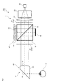
図1は,本発明の実施形態に係る接眼映像表示装置100の構成を模式的に示している。また,図2は,本発明の実施形態に係る接眼映像表示装置100おける光の偏光状態とその進行方向を模式的に示している。図1及び図2に示されるように,接眼映像表示装置100は,表示光学系1と接眼光学系2とを備える。表示光学系1は,光源と液晶ディスプレイなどの映像素子とを備えており,所望の映像光を生成して接眼光学系2に向かって射出する。また,接眼光学系2は,プリズムなどの光学素子を備えており,表示光学系1から射出された映像光を観察者の瞳Eに導く。このため,接眼光学系2は,観察者の瞳Eの近傍に配置されている。これにより,観察者は,表示光学系1によって表示された映像の虚像を視認することができる。
FIG. 1 schematically shows a configuration of an eyepiece
図1に示されるように,表示光学系1は,偏光分離素子10,光源20,偏光板21(第1偏光板21a及び/又は第2偏光板21b),集光レンズ22,均一化素子23,反射部30,及び反射型映像素子40を有している。
As shown in FIG. 1, the display optical system 1 includes a polarized
偏光分離素子10は,直線偏光である第1の偏光成分光を反射させるとともに,第1の偏光成分光とは偏光面の異なる直線偏光である第2の偏光成分光を透過させる光学素子である。図1に示した例において,偏光分離素子10としては,偏光ビームスプリッタ(PBS:Polarizing Beam Splitter)が用いられている。ただし,偏光分離素子10としては,ワイヤーグリッド偏光子などの公知の光分離用の偏光素子を用いることもできる。偏光分離素子10は(PBS)は,直角プリズムを二つ貼り合わせた構造となっており,直角プリズム同士の接合面には誘電体多層膜や金属薄膜などのコーティングが施されている。従って,この接合面が,光をその偏光状態に応じて透過又は分離させる偏光分離面11として機能する。また,図2に示されるように,図1に示した例では,偏光分離面11は,この面に対してS偏光成分の光が入射したときには,このS偏光成分光を略直角に反射し,P偏光成分の光が入射したときには,このP偏光成分光を透過させるものとなっている。ただし,偏光分離面11としては,P偏光成分光を反射し,S偏光成分光を透過させるものを用いることもできる。以下では,S偏光成分光が,偏光分離面11を反射する光成分(第1の偏光成分光)であり,P偏光成分光が,偏光分離面11を透過する光成分(第2の偏光成分光)である場合を例に挙げて説明を行う。
The
光源20は,偏光分離素子10に対して光を出力する。光源20は,図示しない制御回路及び電源に接続されており,この制御回路の制御に従って光を出力する。光源20としは,公知の発光ダイオード(LED:Light Emitting Diode)などを用いることができる。光源20からの出力光には,少なくともS偏光成分光(第1の偏光成分光)が含まれており,これに加えてP偏光成分光(第2の偏光成分光)が含まれていてもよい。
The
図1に示されるように,偏光分離素子10と光源20との間には,第1偏光板21a,集光レンズ22,及び均一化素子23が配置されている。光源20からの出力光は,均一化素子23によって照度等が均一化された後,テレセントリックレンズなどの集光レンズ22によって偏光分離素子10へと導かれる。また,集光レンズ22と偏光分離素子10の間には,第1偏光板21aが配置されている。第1偏光板21aは,光源20からの出力光に含まれるS偏光成分光を透過し,P偏光成分光を遮断する。これにより,光源20の出力光のうち,S偏光成分光のみが,偏光分離素子10へと導入される。また,図1に示されるように,偏光分離素子10と接眼光学系2との間に,第2偏光板21bを設けることもできる。第2偏光板21bは,第1偏光板21aと同様に,S偏光成分光を透過し,P偏光成分光を遮断する。このように,第1偏光板21aと第2偏光板21bの両方又はいずれか一方を設けておくことで,表示光学系1に不要な光が入射することを防止できる。これらの偏光板21(第1偏光板21a及び/又は第2偏光板21b),集光レンズ22,及び均一化素子23としては適宜公知の光学素子を用いることができる。
As shown in FIG. 1, a first
反射部30は,入射した光の偏光状態を変換する機能と,入射した光を反射する機能とを有している。この反射部30は,偏光分離素子10の偏光分離面11において反射された光源20からの出力光(S偏光成分光)が入射する位置に配置されている。図1に示されるように,本実施形態において,反射部30は,1/4波長板31とミラー32とから構成される。1/4波長板31は,入射した光の偏光状態を,直線偏光から円偏光へ又は円偏光から直線偏光へと変換する。1/4波長板31は,偏光分離素子10とミラー32との間に配置されている。このため,1/4波長板31は,偏光分離素子10を反射したS偏光成分光の偏光状態を直線偏光から円偏光に変換するとともに,ミラー32を反射した円偏光を直線偏光へと再変換する。また,1/4波長板31は,ミラー32を反射した円偏光を直線偏光へと再変換する際に,入射した光の位相に対して,再度透過する光の位相を90度ずらして出力する。つまり,1/4波長板31に入射した光がS偏光成分光である場合,ミラー32を反射して再度1/4波長板31を透過する光は,P偏光成分光となる。このように,1/4波長板31とミラー32とから構成される反射部30は,S偏光成分光(第1の偏光成分光)をP偏光成分光(第2の偏光成分光)に変換する機能をもつ。また,ミラー32としては,入射した光をその入射方向へ反射(再帰反射)させることのできる再帰反射ミラーを採用することが好ましい。ただし,ミラー32としては,入射角と反射角が等しくなる通常のミラーを採用することもできる。再帰反射ミラーを採用することのメリットについて,詳しくは後述する。
The
反射型映像素子40は,入射した光を反射するとともに,この入射光(反射光)に所定の変調を施して,観察者に視認させるための映像光を生成する光学部材である。反射型映像素子40としては,例えば,公知の反射型液晶ディスプレイを用いることができる。反射型映像素子40は,偏光分離素子10を挟んで,反射部30(特にミラー32)と対向する位置に配置されている。このため,反射部30において反射した反射光のうち,偏光分離素子10を透過した光(P偏光成分光)が,この反射型映像素子40に入射する。反射型映像素子40は,P偏光成分光を変調して,少なくともS偏光成分光を含む映像光を生成し,この映像光を偏光分離素子10に向かって反射させる。なお,反射型映像素子40には,少なくともS偏光成分光(第1の偏光成分光)が含まれていればよく,これに加えてP偏光成分光(第2の偏光成分光)が含まれていてもよい。
The reflection-
反射型映像素子40によって生成された映像光は,偏光分離素子10に入射し,その偏光分離面11において,映像光に含まれるS偏光成分光(第1の偏光成分光)が略直角に反射され,P偏光成分光(第2の偏光成分光)が透過される。偏光分離素子10によって反射されたS偏光成分光の映像光は,空気中を直進して,接眼光学系2へと入射する。
The image light generated by the
接眼光学系2は,プリズム50を有している。プリズム50は,映像光を内部で導光する導光部材(光学結晶)である。プリズム50は,例えば,映像光の入射面51と,反射面52と,射出面53を有する形状となっている。なお,プリズム50は,単一のプリズムで構成されてもよいし,複数のプリズムを組み合わせて構成されてもよい。プリズム50の入射面51は,映像光の光軸と垂直に交差する方向に設けられている。また,射出面53は,観察者の瞳Eと対面するように設けられている。反射面52は,例えば矩形形状(長方形形状)であり,映像光の光路を直角に折り曲げる手段として機能している。具体的には,反射面52は,入射面51を介してプリズム内部に入射して映像光を略直角に反射して,射出面53から射出させる。これにより,接眼光学系2のプリズム50内部に導かれた映像光が,観察者の瞳Eへと入射する。
The eyepiece
続いて,本発明に係る接眼映像表示装置100の動作を,図2を参照して説明する。
図2に示されるように,光源20から出力された光は,均一化素子23及び集光レンズ22を介して第1偏光板21aへと入射する。第1偏光板21aは,光源20からの出力光のうち,S偏光成分光(第1の偏光成分光)のみを透過させ,P偏光成分光(第2の偏光成分光)を遮断する。第1偏光板21aを透過したS偏光成分光は,偏光分離素子10へと入射して,この偏光分離面11において略直角に反射し,反射部30へと導かれる。反射部30において,S偏光成分光は,1/4波長板31を通過する際に円偏光へと変換され,ミラー32によって入射方向と同一の方向に反射され,再度1/4波長板31を通過する。この際,ミラー32を反射した円偏光が,P偏光成分光へと変換される。このようにして反射部30から射出されたP偏光成分光は,偏光分離素子10を通過して,反射型映像素子40に入射する。反射型映像素子40は,P偏光成分光を変調して,少なくともS偏光成分光を含む映像光を生成するとともに,この映像光を偏光分離素子10へ向けて反射させる。S偏光成分光を含む映像光は,偏光分離素子10の偏光分離面11において略直角に反射され,空気中を伝搬して,接眼光学系2を構成するプリズム50へと導かれる。なお,偏光分離素子10とプリズム50との間に,第1偏光板21aに代えて,又は第1偏光板21aと共に,第2偏光板21bを設けることもできる。第2偏光板21bにより,偏光分離素子10を透過したP偏光成分光を遮断することとしてもよい。そして,プリズム50は,入射した映像光を観察者の瞳Eへと導く。これにより,光源20から出力された光を反射型映像素子40によって変調して映像光を生成し,この映像光を観察者に視認させることが可能となる。
Next, the operation of the eyepiece
As shown in FIG. 2, the light output from the
図1及び図2に示されるように,本発明の接眼映像表示装置100では,光源20と,偏光分離素子10と,プリズム50とを,一直線上に配置することができる。つまり,偏光分離素子10とプリズム50とは,光源20から出力された光の主軸方向に位置している。従って,本発明によれば,光源20と,偏光分離素子10と,プリズム50とを一直線上に並べたスリムな構成を実現することができ,接眼映像表示装置100及びそれを備えたHMDの設計の自由度を高めることができる。
As shown in FIGS. 1 and 2, in the eyepiece
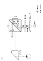
続いて,上述したミラー32として,再帰反射ミラーを用いることのメリットについて説明する。
まず,図3は,接眼映像表示装置100における光路をモデル化したものであり,通常のミラーを用いた場合の例を示している。通常のミラー32は,光の入射角と反射角が等しくなる。このような通常のミラー32を用いた場合において,反射型映像素子40を中心に装置内を伝搬する光の分散幅を図3に示すと,その光の分散幅が広くなり,装置内から外部へと進行する光も出現している。このため,通常のミラー32を用いると,光源20から出力された光のうち,接眼光学系2へと導かれる光量が減少して,観察者に視認される映像が暗くなるという問題がある。従って,観察者に視認される映像の明度を一定以上とするためには,光源20から出力される光の強度を高くしなければならず照明系に負担がかかる。また,装置内の光が外部へと漏れないようにするためには,光の光路長を長くするか,若しくは光を集光するためのレンズの枚数を増やす必要がある。そうすると,通常のミラー32を用いた場合には,装置の構成物品が増えたり,装置の構成が大型化するという問題がある。
Next, the merit of using a retroreflective mirror as the above-described
First, FIG. 3 is a model of an optical path in the eyepiece
図4は,ミラー32として再帰反射ミラーを用いた場合のモデル図を示している。再帰反射ミラーは,入射した光をその入射方向へ反射(再帰反射)させることができる。図4に示されるように,再帰反射ミラー32を用いた場合,装置内を伝搬する光の分散幅は,図3に示した通常のミラーを用いた場合と比較して,装置内に収まる程度に狭くなっている。つまり,再帰反射ミラー32を用いることにより,装置内から外部へ光が漏れ出すことを防止できる。これにより,光源20から出力された光のほぼ全量を,反射型映像素子40へと導きことができ,さらには反射型映像素子40によって生成された映像光のほぼ全量を,接眼光学系2へと導くことも可能である。従って,再帰反射ミラー32を用いることにより,通常のミラーを採用した場合と比較して,光源20から出力される光の強度を低く設定しておくことができる。これにより,照明系の負担を軽減でき,接眼映像表示装置を駆動するバッテリーを節約することができる。また,再帰反射ミラー32を用いることで光の分散を抑えることができるため,光の光路長を短くすることができる。また,余計なレンズ等の光学部品が不要となり,装置全体の構成を簡略化することが可能である。従って,再帰反射ミラー32を用いることで,低コスト且つコンパクトな接眼映像表示装置100を実現することができる。
FIG. 4 shows a model diagram when a retroreflective mirror is used as the
本発明の接眼映像表示装置100は,HMDに搭載される映像表示装置として用いることが好ましい。具体的には,HMDは,使用者の頭部又は首周りに装着されて,接眼映像表示装置100の接眼光学系2を,この使用者の片眼又は両眼の眼前に配置する構造を有している。その他に,HMDには,カメラや,マイク,ジャイロセンサ,光センサなどの各種センサ機器を搭載することもできる。HMDの構成は適宜公知のものを採用すればよい。例えば,特許5420793号や特許5593429号に開示されたHMDの構成を,採用することができる。
The eyepiece
以上,本願明細書では,本発明の内容を表現するために,図面を参照しながら本発明の実施形態の説明を行った。ただし,本発明は,上記実施形態に限定されるものではなく,本願明細書に記載された事項に基づいて当業者が自明な変更形態や改良形態を包含するものである。 As mentioned above, in this specification, in order to express the content of this invention, embodiment of this invention was described, referring drawings. However, the present invention is not limited to the above-described embodiments, but includes modifications and improvements obvious to those skilled in the art based on the matters described in the present specification.
本発明は,HMDなどに搭載される接眼型の映像表示装置に関するものである。このため,本発明はウェアラブルデバイスの製造産業において好適に利用することができる。 The present invention relates to an eyepiece-type image display device mounted on an HMD or the like. Therefore, the present invention can be suitably used in the wearable device manufacturing industry.
1…表示光学系 2…接眼光学系 10…偏光分離素子
11…偏光分離面 20…光源 21…偏光板
22…集光レンズ 23…均一化素子 30…反射部
31…1/4波長板 32…ミラー 40…反射型映像素子
50…プリズム 51…入射面 52…反射面
53…射出面 100…接眼映像表示装置
DESCRIPTION OF SYMBOLS 1 ... Display
Claims (6)
前記表示光学系(1)から射出された映像光を観察者の瞳に導く接眼光学系(2)と,を備える
接眼映像表示装置であって,
前記表示光学系(1)は,
直線偏光である第1の偏光成分光を反射させるとともに,前記第1の偏光成分光とは偏光面の異なる直線偏光である第2の偏光成分光を透過させる偏光分離素子(10)と,
前記偏光分離素子(10)に光を出力する光源(20)と,
前記偏光分離素子(10)を反射した前記光源(20)からの出力光に含まれる前記第1の偏光成分光を前記第2の偏光成分光に変換するとともに,前記出力光を反射して,前記偏光分離素子(10)へと入射させる反射部(30)と,
前記偏光分離素子(10)を透過した前記反射部(30)からの反射光を反射するとともに,当該反射光を少なくとも前記第1の偏光成分光を含む前記映像光に変換して,前記偏光分離素子(10)へと入射させる反射型映像素子(40)と,を有し,
前記偏光分離素子(10)を反射した前記映像光に含まれる前記第1の偏光成分光が,前記接眼光学系(2)に入射する
接眼映像表示装置。 A display optical system (1) for emitting image light;
An eyepiece image display device comprising: an eyepiece optical system (2) for guiding image light emitted from the display optical system (1) to an observer's pupil;
The display optical system (1)
A polarization separation element (10) that reflects the first polarization component light that is linearly polarized light and transmits the second polarization component light that is linearly polarized light having a polarization plane different from that of the first polarization component light;
A light source (20) for outputting light to the polarization separation element (10);
Converting the first polarization component light contained in the output light from the light source (20) reflected from the polarization separation element (10) into the second polarization component light, and reflecting the output light; A reflecting portion (30) that is incident on the polarization separation element (10);
Reflecting the reflected light from the reflecting section (30) that has passed through the polarization separating element (10), and converting the reflected light into the image light including at least the first polarization component light, thereby the polarization separation. A reflective image element (40) incident on the element (10),
An eyepiece image display device in which the first polarized component light included in the image light reflected from the polarization separation element (10) is incident on the eyepiece optical system (2).
請求項1に記載の接眼映像表示装置。 The eyepiece image display device according to claim 1, wherein the eyepiece optical system (2) , the polarization separation element (10), and the light source (20) are aligned on a straight line.
前記光源(20)と前記偏光分離素子(10)との間及び前記偏光分離素子(10)と前記接眼光学系(2)との間の両方又はいずれか一方に,前記光源(20)からの出力光に含まれる前記第1の偏光成分光を透過させ,前記第2の偏光成分光を遮断する偏光板(21)を,さらに有する
請求項1又は請求項2に記載の接眼映像表示装置。 The display optical system (1)
From the light source (20) between the light source (20) and the polarization separation element (10) and / or between the polarization separation element (10) and the eyepiece optical system (2). The eyepiece image display device according to claim 1 or 2, further comprising a polarizing plate (21) that transmits the first polarized component light included in the output light and blocks the second polarized component light.
前記1/4波長板(31)は,前記偏光分離素子(10)を反射した前記光源(20)からの出力光に含まれる前記第1の偏光成分光を円偏光に変換し,前記ミラー(32)に入射させ,
前記ミラー(32)は,前記1/4波長板(31)を経た前記円偏光を反射し,
前記1/4波長板(31)は,前記ミラー(32)を反射した前記円偏光を前記第2の偏光成分光に変換して,前記偏光分離素子(10)へと入射させる
請求項1から請求項3のいずれかに記載の接眼映像表示装置。 The reflection part (30) includes a quarter wave plate (31) and a mirror (32),
The quarter-wave plate (31) converts the first polarization component light included in the output light from the light source (20) reflected from the polarization separation element (10) into circularly polarized light, and the mirror ( 32)
The mirror (32) reflects the circularly polarized light that has passed through the quarter-wave plate (31),
The quarter-wave plate (31) converts the circularly polarized light reflected by the mirror (32) into the second polarization component light and makes it incident on the polarization separation element (10). The eyepiece image display apparatus according to claim 3.
請求項4に記載の接眼映像表示装置。 The eyepiece image display device according to claim 4, wherein the mirror (32) is a retroreflective mirror.
ヘッドマウントディスプレイ。 A head mounted display comprising the eyepiece video display device according to any one of claims 1 to 5.
Priority Applications (3)
| Application Number | Priority Date | Filing Date | Title |
|---|---|---|---|
| JP2015028072A JP6081508B2 (en) | 2015-02-16 | 2015-02-16 | Linear eyepiece display device |
| US15/551,273 US20180039065A1 (en) | 2015-02-16 | 2015-09-28 | Linearly disposed eyepiece video display |
| PCT/JP2015/077270 WO2016132584A1 (en) | 2015-02-16 | 2015-09-28 | Linearly disposed eyepiece video display |
Applications Claiming Priority (1)
| Application Number | Priority Date | Filing Date | Title |
|---|---|---|---|
| JP2015028072A JP6081508B2 (en) | 2015-02-16 | 2015-02-16 | Linear eyepiece display device |
Publications (3)
| Publication Number | Publication Date |
|---|---|
| JP2016151626A JP2016151626A (en) | 2016-08-22 |
| JP2016151626A5 JP2016151626A5 (en) | 2016-12-28 |
| JP6081508B2 true JP6081508B2 (en) | 2017-02-15 |
Family
ID=56688855
Family Applications (1)
| Application Number | Title | Priority Date | Filing Date |
|---|---|---|---|
| JP2015028072A Active JP6081508B2 (en) | 2015-02-16 | 2015-02-16 | Linear eyepiece display device |
Country Status (3)
| Country | Link |
|---|---|
| US (1) | US20180039065A1 (en) |
| JP (1) | JP6081508B2 (en) |
| WO (1) | WO2016132584A1 (en) |
Families Citing this family (6)
| Publication number | Priority date | Publication date | Assignee | Title |
|---|---|---|---|---|
| CN107422484B (en) * | 2017-09-19 | 2023-07-28 | 歌尔光学科技有限公司 | Prismatic AR display device |
| CN108459416B (en) * | 2018-04-12 | 2021-08-06 | 京东方科技集团股份有限公司 | Lighting device, display equipment and near-to-eye display system |
| JP2019197124A (en) * | 2018-05-09 | 2019-11-14 | セイコーエプソン株式会社 | Projection type display device |
| CN110501813B (en) * | 2018-05-17 | 2021-08-31 | 中强光电股份有限公司 | Display device |
| JP2022156074A (en) * | 2021-03-31 | 2022-10-14 | セイコーエプソン株式会社 | Optical module and head-mounted display device |
| CN114355501A (en) * | 2022-01-27 | 2022-04-15 | 珠海莫界科技有限公司 | Optical display module |
Family Cites Families (13)
| Publication number | Priority date | Publication date | Assignee | Title |
|---|---|---|---|---|
| US3677621A (en) * | 1969-11-24 | 1972-07-18 | Vickers Ltd | Optical field flattening devices |
| US3704061A (en) * | 1970-03-25 | 1972-11-28 | David Neil Travis | Wavelength selective mirror systems |
| US5383053A (en) * | 1992-04-07 | 1995-01-17 | Hughes Aircraft Company | Virtual image display having a high efficiency grid beamsplitter |
| US5596451A (en) * | 1995-01-30 | 1997-01-21 | Displaytech, Inc. | Miniature image generator including optics arrangement |
| US6310713B2 (en) * | 1997-04-07 | 2001-10-30 | International Business Machines Corporation | Optical system for miniature personal displays using reflective light valves |
| JP4341108B2 (en) * | 1999-07-14 | 2009-10-07 | ソニー株式会社 | Virtual image observation optical device |
| JP2001117045A (en) * | 1999-10-21 | 2001-04-27 | Shimadzu Corp | Display device |
| JP2001177851A (en) * | 1999-12-17 | 2001-06-29 | Minolta Co Ltd | Head-mounted video display device |
| US6693743B2 (en) * | 2000-06-07 | 2004-02-17 | Cirvine Corporation | Birefringent devices |
| GB0112871D0 (en) * | 2001-05-26 | 2001-07-18 | Thales Optics Ltd | Improved optical device |
| JP3966003B2 (en) * | 2002-02-05 | 2007-08-29 | 日産自動車株式会社 | Internal combustion engine |
| EP1731943B1 (en) * | 2004-03-29 | 2019-02-13 | Sony Corporation | Optical device and virtual image display device |
| US7675684B1 (en) * | 2007-07-09 | 2010-03-09 | NVIS Inc. | Compact optical system |
-
2015
- 2015-02-16 JP JP2015028072A patent/JP6081508B2/en active Active
- 2015-09-28 US US15/551,273 patent/US20180039065A1/en not_active Abandoned
- 2015-09-28 WO PCT/JP2015/077270 patent/WO2016132584A1/en active Application Filing
Also Published As
| Publication number | Publication date |
|---|---|
| JP2016151626A (en) | 2016-08-22 |
| US20180039065A1 (en) | 2018-02-08 |
| WO2016132584A1 (en) | 2016-08-25 |
Similar Documents
| Publication | Publication Date | Title |
|---|---|---|
| JP6081508B2 (en) | Linear eyepiece display device | |
| US11415812B2 (en) | Compact collimating optical device and system | |
| US10386563B2 (en) | Illuminator for a wearable display | |
| CN111158079B (en) | Light guide with multiple in-coupling holograms for head wearable displays | |
| KR102323214B1 (en) | Optical device for augmented reality | |
| EP2732328B1 (en) | Eyepiece for near-to-eye display with multi-reflectors | |
| US10007121B2 (en) | See-through head-mounted display | |
| US20120243204A1 (en) | Efficient polarized directional backlight | |
| EP3163356A1 (en) | Image display device | |
| CN112969955A (en) | Optical device and system with dichroic beamsplitter color combiner | |
| US20200192111A1 (en) | Image device with a compact homogenizer | |
| WO2015007201A1 (en) | Wearable flat optical system | |
| US11442271B2 (en) | Display illumination systems | |
| JP2017058400A (en) | Image display device | |
| JP2009134087A (en) | Image display device and head mount display | |
| CN111158143B (en) | Micro projection light engine for near-eye display device | |
| US11899210B2 (en) | Wearable image display device | |
| JP6610675B2 (en) | Light guiding element, bonding optical element, image display device, and head mounted display | |
| JP2018004764A (en) | Picture image display device and eyepiece optical system | |
| TW202409470A (en) | Light guide display system including freeform volume grating | |
| KR20230051050A (en) | Augmented reality device | |
| CN112505821A (en) | Light guide module and augmented reality device | |
| JP2018036558A (en) | Image display device and eyepiece optical system | |
| JPWO2011125479A1 (en) | Polarized light guide plate, illumination device, and projection display device |
Legal Events
| Date | Code | Title | Description |
|---|---|---|---|
| A521 | Request for written amendment filed |
Free format text: JAPANESE INTERMEDIATE CODE: A523 Effective date: 20161110 |
|
| A621 | Written request for application examination |
Free format text: JAPANESE INTERMEDIATE CODE: A621 Effective date: 20161110 |
|
| A871 | Explanation of circumstances concerning accelerated examination |
Free format text: JAPANESE INTERMEDIATE CODE: A871 Effective date: 20161110 |
|
| A975 | Report on accelerated examination |
Free format text: JAPANESE INTERMEDIATE CODE: A971005 Effective date: 20161216 |
|
| TRDD | Decision of grant or rejection written | ||
| A01 | Written decision to grant a patent or to grant a registration (utility model) |
Free format text: JAPANESE INTERMEDIATE CODE: A01 Effective date: 20170110 |
|
| A61 | First payment of annual fees (during grant procedure) |
Free format text: JAPANESE INTERMEDIATE CODE: A61 Effective date: 20170118 |
|
| R150 | Certificate of patent or registration of utility model |
Ref document number: 6081508 Country of ref document: JP Free format text: JAPANESE INTERMEDIATE CODE: R150 |
|
| S111 | Request for change of ownership or part of ownership |
Free format text: JAPANESE INTERMEDIATE CODE: R313111 |
|
| S533 | Written request for registration of change of name |
Free format text: JAPANESE INTERMEDIATE CODE: R313533 |
|
| R350 | Written notification of registration of transfer |
Free format text: JAPANESE INTERMEDIATE CODE: R350 |
|
| R250 | Receipt of annual fees |
Free format text: JAPANESE INTERMEDIATE CODE: R250 |
|
| R250 | Receipt of annual fees |
Free format text: JAPANESE INTERMEDIATE CODE: R250 |
|
| R250 | Receipt of annual fees |
Free format text: JAPANESE INTERMEDIATE CODE: R250 |
|
| R250 | Receipt of annual fees |
Free format text: JAPANESE INTERMEDIATE CODE: R250 |
|
| S111 | Request for change of ownership or part of ownership |
Free format text: JAPANESE INTERMEDIATE CODE: R313111 |
|
| R350 | Written notification of registration of transfer |
Free format text: JAPANESE INTERMEDIATE CODE: R350 |